
GSM-CONTROL SMS Gateway Software -
127
GSM-CONTROL SMS Gateway Software for M2M remote control in automation applications using GSM communications User Manual Ver 4.x Rev 4.5 PR 000 67 WONDERWARE FINLAND & BALTICS P.O. Box 38 FIN-00371 Helsinki Finland tel. int. + 358 9 5404940 fax int. + 358 9 5413541 [email protected] www.wonderware.fi
Transcript of GSM-CONTROL SMS Gateway Software -
GSM-CONTROL SMS Gateway Software
for M2M remote control in automation applications using GSM communications
User Manual
Ver 4.x Rev 4.5
PR 000 67
WONDERWARE FINLAND & BALTICS P.O. Box 38 FIN-00371 Helsinki Finland tel. int. + 358 9 5404940 fax int. + 358 9 5413541 [email protected] www.wonderware.fi
Wonderware Finland & Baltics GSM-Control i
GSM-Control User Manual Ver. 4.x Rev 4.5 P067m45.docx
Table Of Contents
Overview .................................................................................................... 1 GSM-modem and accessories ............................................................................ 3 Installing the GSM-Control ............................................................................... 5
Licensing by using HASP HL key ................................................................................... 9 Software license key ........................................................................................................ 10
Transferring the software license to other computer .......................................................... 11 Getting started quickly with GSM-Control ............................................................ 12
Getting started in simulation mode (without GSM-modem connected)......................... 12 Getting started with GSM-modem connected ................................................................. 14
GSM-Control user interface .............................................................................. 17
GSM-Control Configuration Program ............................................................................. 17 GSMCFG Main Window ........................................................................................................ 17 Editing data in ”Users&Data” and ”Messages” Pages ......................................................... 18 ”Users” Page ........................................................................................................................... 19 ”Data” Page ............................................................................................................................. 21 ”Send/Receive” Page ............................................................................................................... 23
Contents of Send/Receive messages ............................................................................ 25 Linking Users with Send/Receive messages .............................................................. 26
”Alarms” Page ......................................................................................................................... 27 Alarm and Ack Items ................................................................................................... 28 Alarm Message and Ack Message ............................................................................... 29 Options .......................................................................................................................... 29 Users ............................................................................................................................. 30
GSMCFG Main Menu ............................................................................................................ 32 File ................................................................................................................................ 32 Settings ......................................................................................................................... 33 Help ............................................................................................................................... 34
GSM-Control Communication Program ......................................................................... 35 Communication Protocols ...................................................................................................... 35 Starting GSMCTRL ............................................................................................................... 36 GSMCTRL Menu Commands ................................................................................................ 38
File ................................................................................................................................ 38 Options .......................................................................................................................... 38 Send .............................................................................................................................. 44 Help ............................................................................................................................... 45
Examples how to use GSM-Control ..................................................................... 46
GSM-Control with MS Excel (DDE)................................................................................ 47 Starting sequence ................................................................................................................... 47 Receiving/Sending SMS message .......................................................................................... 49 Sending Alarm message and receiving Acknowledgment ................................................... 50 Sending any SMS message to any phone number ............................................................... 53 Sending any SMS message to phone number configured in GSM-Control ........................ 54 Sending “1-way messages” ..................................................................................................... 55 Sending “Send messages” ...................................................................................................... 55
GSM-Control with Wonderware InTouch (DDE) ............................................................ 56 Starting sequence ................................................................................................................... 57 Receiving/Sending SMS messages ........................................................................................ 57 Sending Alarm message and receiving Acknowledgment ................................................... 60
GSM-Control with OPC Server ....................................................................................... 63 Starting sequence ................................................................................................................... 64
Wonderware Finland & Baltics GSM-Control ii
GSM-Control User Manual Ver. 4.x Rev 4.5 P067m45.docx
Receiving/Sending SMS message .......................................................................................... 65 GSM-Control with Wonderware Application Server ...................................................... 70
Starting sequence ................................................................................................................... 70 Receiving/Sending SMS message .......................................................................................... 70
GSM-Control with SQL database ................................................................................... 74 Starting sequence ................................................................................................................... 74 Reading values from SQL database ...................................................................................... 75 Writing values to SQL database ........................................................................................... 79
Example of forwarding received SMS message to e-mail ............................................... 86 Additional features ........................................................................................ 88
One direction sending of SMS messages from GSM-Control ......................................... 88 Sending “1-way” Messages .................................................................................................... 88 Sending “Send” Messages ...................................................................................................... 94
GSMCTRL.INI file .......................................................................................................... 96 SendErrorRetries entry ......................................................................................................... 96 NoAlarmIfAck entry .............................................................................................................. 97 Entries for alternative (voice) call support in case SMS Service not available ................. 97 AlarmCheckInterval .............................................................................................................. 97 ModemRestartTimeout .......................................................................................................... 98 ModemRestartPeriod ............................................................................................................. 98
Special Character Sets .................................................................................................... 98 SMS Message Prefixes .................................................................................................... 99 Mode settings ................................................................................................................... 99 Unicode settings .............................................................................................................. 99 Debug settings ................................................................................................................. 100 User extension DLL......................................................................................................... 100 Enabling Wonderware MXAccess (LMX) interface ........................................................ 101 Running GSMCTRL as Windows Service ....................................................................... 101 Running GSMCTRL as OPC Server ............................................................................... 102 Configuring DCOM.......................................................................................................... 103
Configuring DCOM to access GSM-Control as a local OPC Server .................................... 103 Configuring DCOM to access GSM-Control as a remote OPC Server ................................ 104 Most frequent errors when configuring DCOM ................................................................... 105
Sending messages by using DDE or OPC ....................................................................... 106 DDE items .............................................................................................................................. 106 Sending SMS message by using DDE ................................................................................... 111 Sending SMS message when DDE client terminates the connection ................................. 111 Special "DUMMY" Topic ........................................................................................................ 111 OPC Items .............................................................................................................................. 112 Sending SMS message by using OPC ................................................................................... 115
Sending and Receiving messages by e-mail .................................................................... 116 Time Shifts ...................................................................................................................... 118
Errors ........................................................................................................ 118
Wonderware Finland & Baltics GSM-Control 1
GSM-Control User Manual Ver. 4.x Rev 4.5 P067m45.docx
GSM-CONTROL
Overview
GSM-CONTROL SMS Gateway is a Microsoft Windows software used for 2-way
remote control in automation and other applications using standard GSM (Global
System for Mobiles) cellular phones and GSM network. Based on the standard
GSM cellular phones and other GSM-capable devices, GSM-Control offers a low-
cost and easy alternative to create wireless control and monitoring applications.
Implementation of GSM network’s SMS (SMS Message Service) technology
secures reliable transmission even in the most error-sensitive applications.
The main task of GSM-Control software is to work as a gateway between GSM
environment at one side (interfacing with GSM environment by sending/receiving
SMS messages) and MS Windows environment (by using DDE (Dynamic Data
Exchange), OPC (OLE for Process Control), SQL (Structured Query Language) or
Wonderware MXAccess (Lmx Proxy interface to Application Server) interfaces) at
another side.
The GSM-Control runs on a PC and accesses operator interface applications or
directly field devices by using DDE, OPC or MXAccess interfaces. GSM-Control
also supports the reading/writing of data from/to SQL databases. The remote
control is based on GSM SMS messages two-direction communication, where the
GSM-modem (preferable models are Siemens TC35T/MC35T) is connected to the
computer's standard (RS-232) serial port and GSM cellular phone (remote GSM
phone) is used by remote operator(s). Also the communication between two GSM-
modems is supported, i.e. remote GSM-modems can be used instead of remote
GSM phone.
The GSM-Control software includes two MS Windows application programs: GSM-
Control Configuration Program (GSMCFG) and GSM-Control Communication
Program (GSMCTRL, further in the text also GSM-Control). The GSMCFG is
used to prepare the source information and GSMCTRL is used to perform the
GSM SMS communications and DDE/OPC/SQL/MXAccess data exchange on the
basis on information prepared by GSMCFG. These two application programs are
completely independent, i.e. each can work separately and doesn’t need another
program to be started. The data prepared by GSMCFG is saved in GSM-Control
configuration file - XML (eXtensible Markup Language) format file used as an
input file for GSMCTRL program. As many GSM-Control configuration files can
be created as necessary.
Basically, the data exchange through GSM-Control can be initiated both from
GSM and MS Windows environments:
Wonderware Finland & Baltics GSM-Control 2
GSM-Control User Manual Ver. 4.x Rev 4.5 P067m45.docx
1 From GSM environment - by sending SMS message to GSM-Control, where the
received message is checked and processed according the GSM-Control current
configuration. The received SMS message can contain some data to be
transferred via DDE, OPC, SQL or MXAccess from GSM-Control to other MS
Windows applications (e.g. to PC operator interface applications or field devices
through appropriate communication servers) or databases. This SMS message
received can have the corresponding response message configured (also possibly
containing data values obtained by via DDE, OPC, SQL or MXAccess) - in this
case GSM-Control will respond with SMS message to the sender.
2 From MS Windows environment - when some alarm or event occurs in MS
Windows application (e.g. in PC operator interface application or directly in the
field device) and the corresponding alarm or event condition is specified in
GSM-Control. In this case GSM-Control will send the correspondingly
configured SMS message (possibly containing also some data obtained via DDE,
OPC, SQL or MXAccess) to remote GSM operator or device linked to this alarm
or event condition. The receiver of such SMS message can respond to GSM-
Control - for example, send some acknowledgment SMS message possibly
containing some data for delivery via DDE, OPC, SQL or MXAccess.
Moreover, it is possible to send (manually or automatically through DDE, OPC or
MXAccess) any pre-configured text message (“standard 1-way messages”) from
GSM-Control to remote GSM operator or device. The SMS messages also can be
received from any (not configured) phone number (so called “ANYUSER” feature)
and correspondingly replied with information depending on contents of received
message.
The GSM-Control can be used on Internet - it is possible to send SMS messages by
e-mails from GSM-Control to GSM network and to receive SMS messages as e-
mails from GSM network. In this case GSM-Control may run without GSM-
modem connected - modem is replaced by e-mail connection.
The GSM-Control may be accessed by any Microsoft Windows (NT, 2000, XP)
program working as a DDE or OPC Server (or DDE or OPC Client in case of direct
sending/receiving of SMS Messages via GSM-Control). The GSM-Control has
extended functions and support for Wonderware InTouch (for MMI),
Application Server (via MXAccess) and for I/O Servers (for field
interfacing) developed with Wonderware I/O Server Development Toolkit.
Wonderware Finland & Baltics GSM-Control 3
GSM-Control User Manual Ver. 4.x Rev 4.5 P067m45.docx
GSM-modem and accessories
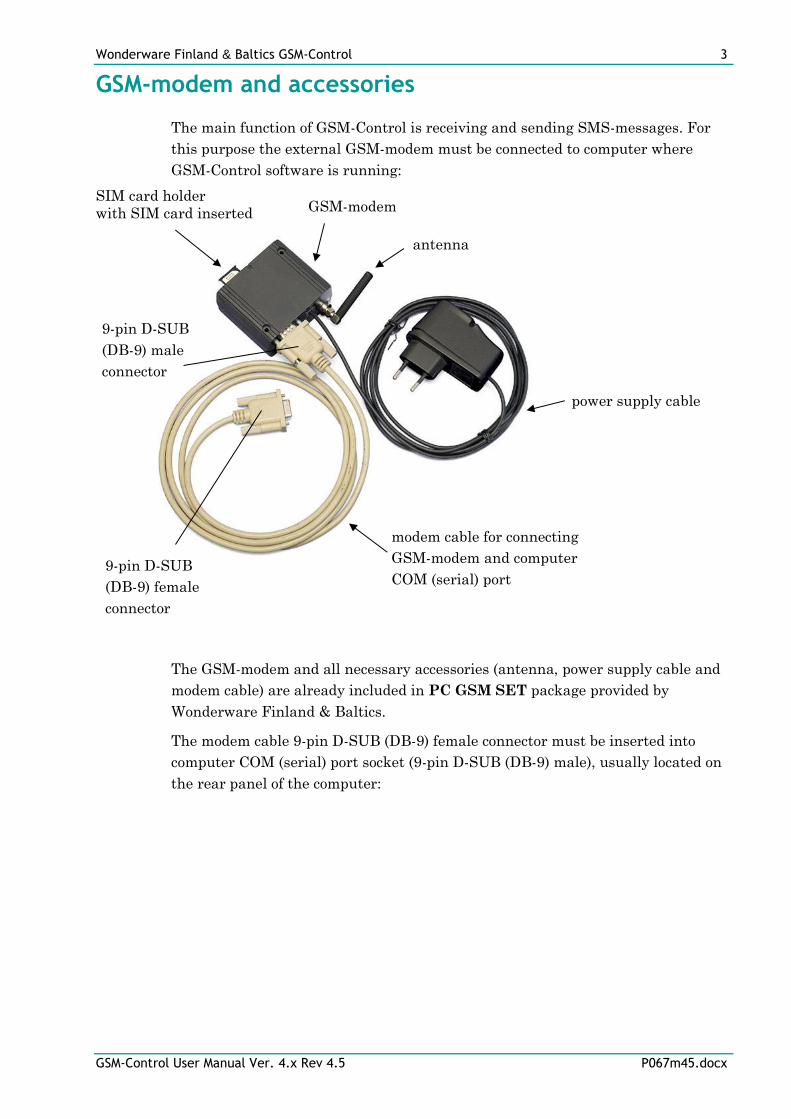
The main function of GSM-Control is receiving and sending SMS-messages. For
this purpose the external GSM-modem must be connected to computer where
GSM-Control software is running:
The GSM-modem and all necessary accessories (antenna, power supply cable and
modem cable) are already included in PC GSM SET package provided by
Wonderware Finland & Baltics.
The modem cable 9-pin D-SUB (DB-9) female connector must be inserted into
computer COM (serial) port socket (9-pin D-SUB (DB-9) male), usually located on
the rear panel of the computer:
SIM card holder
with SIM card inserted GSM-modem
antenna
power supply cable
9-pin D-SUB
(DB-9) male
connector
9-pin D-SUB
(DB-9) female
connector
modem cable for connecting
GSM-modem and computer
COM (serial) port
Wonderware Finland & Baltics GSM-Control 4
GSM-Control User Manual Ver. 4.x Rev 4.5 P067m45.docx
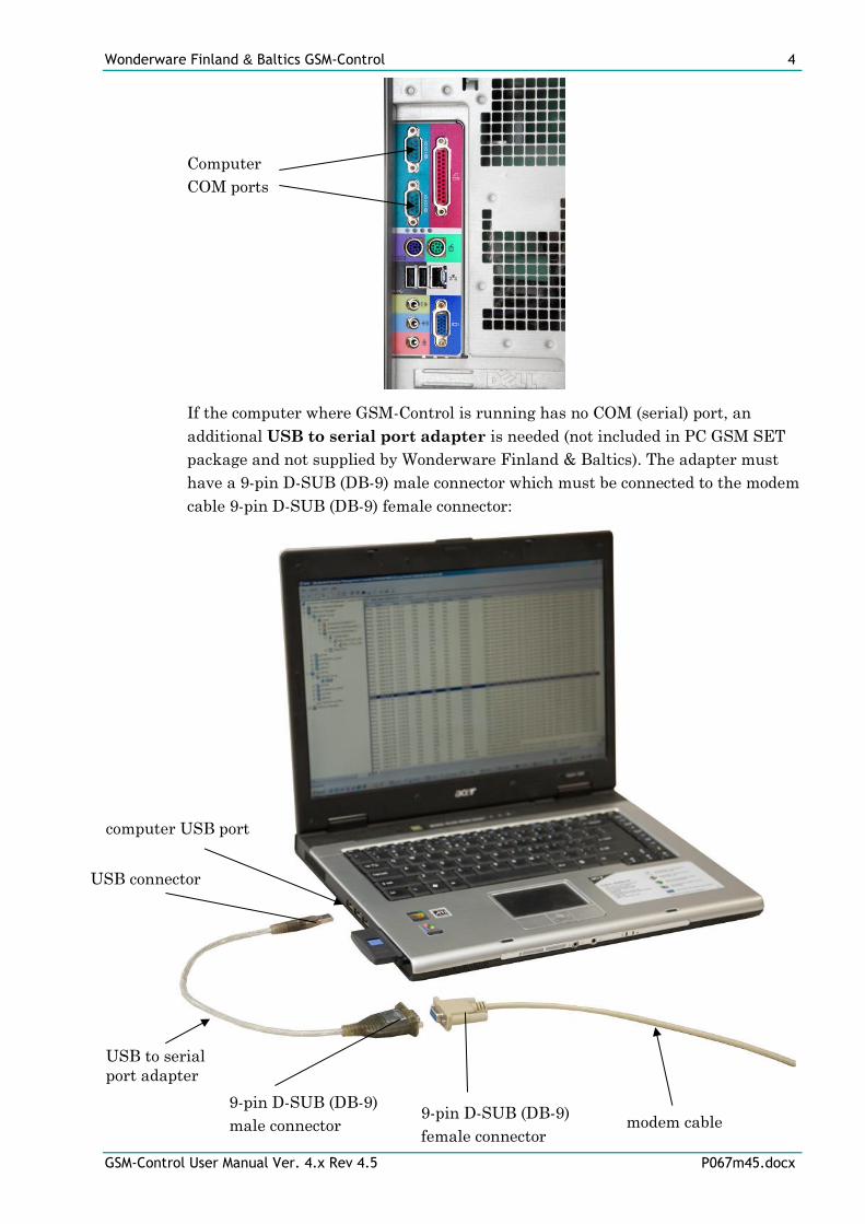
computer USB port
USB to serial
port adapter
9-pin D-SUB (DB-9)
male connector 9-pin D-SUB (DB-9)
female connector
USB connector
modem cable
If the computer where GSM-Control is running has no COM (serial) port, an
additional USB to serial port adapter is needed (not included in PC GSM SET
package and not supplied by Wonderware Finland & Baltics). The adapter must
have a 9-pin D-SUB (DB-9) male connector which must be connected to the modem
cable 9-pin D-SUB (DB-9) female connector:
Computer
COM ports
Wonderware Finland & Baltics GSM-Control 5
GSM-Control User Manual Ver. 4.x Rev 4.5 P067m45.docx
There are different kinds of USB to serial port adapters available on the market,
as a rule also the corresponding USB/serial driver software is supplied – after
installing the driver, the new virtual COM port (physically using USB port) is
added to the computer; this COM port must be selected in GSM-Control as a COM
port where GSM-modem is connected.
Installing the GSM-Control
The GSM-Control installation package is supplied as a Microsoft Installer file
P067_xxx.msi, where xxx is the current (latest) version of GSM-Control.
To install the GSM-Control, run the P067_xxx.msi and proceed as directed by the
GSM-Control Setup Wizard. The installation is simple and straightforward, only it
is important to select the correct protection (HASP key or software license) in
“Custom Setup” dialog.
The HASP key or software license key is needed for full time running of GSM-
Control. The HASP key is an USB key (dongle) to be installed into PC USB port
and needs the SafeNet Sentinel LDK Run-time Environment (HASP HL Runtime
Package) to be installed and running – see details in “Licensing by using HASP
HL key” section below. The software license key is a 16-character alphanumeric
“computer-dependent” string, provided after purchasing the GSM-Control (for
more information, see “Software license key” section below. Without HASP key
installed or software license key entered, the GSM-Control will run one hour in
demo mode. After purchasing the GSM-Control, the appropriate HASP key or
software license key is provided and no re-installation of GSM-Control is needed.
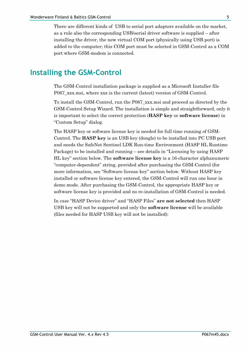
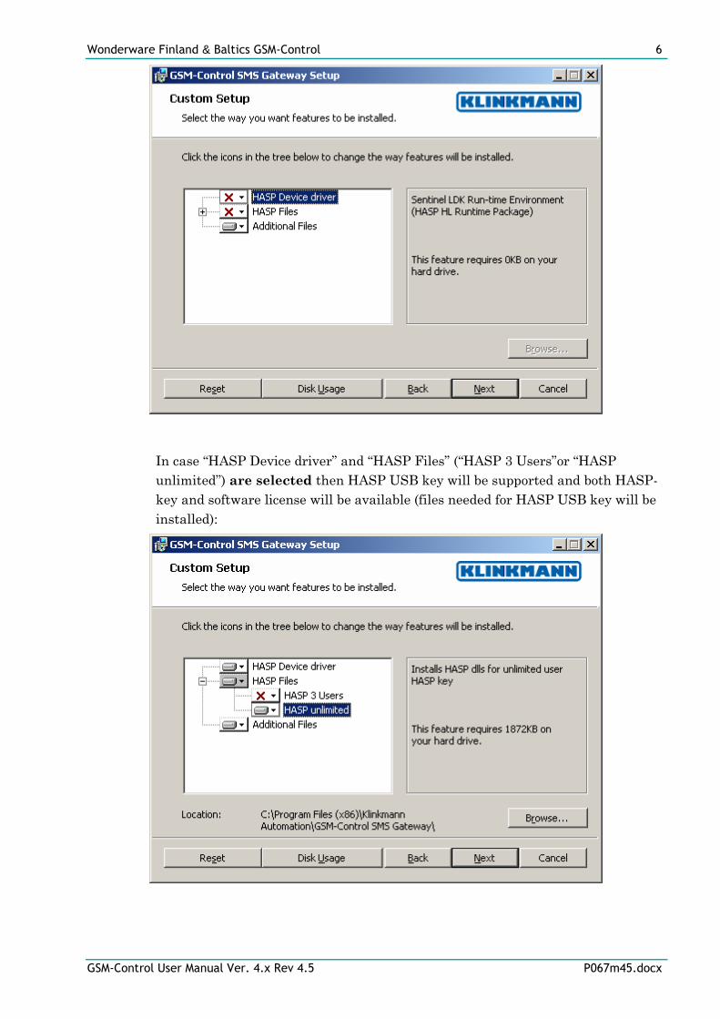
In case “HASP Device driver” and “HASP Files” are not selected then HASP
USB key will not be supported and only the software license will be available
(files needed for HASP USB key will not be installed):
Wonderware Finland & Baltics GSM-Control 6
GSM-Control User Manual Ver. 4.x Rev 4.5 P067m45.docx
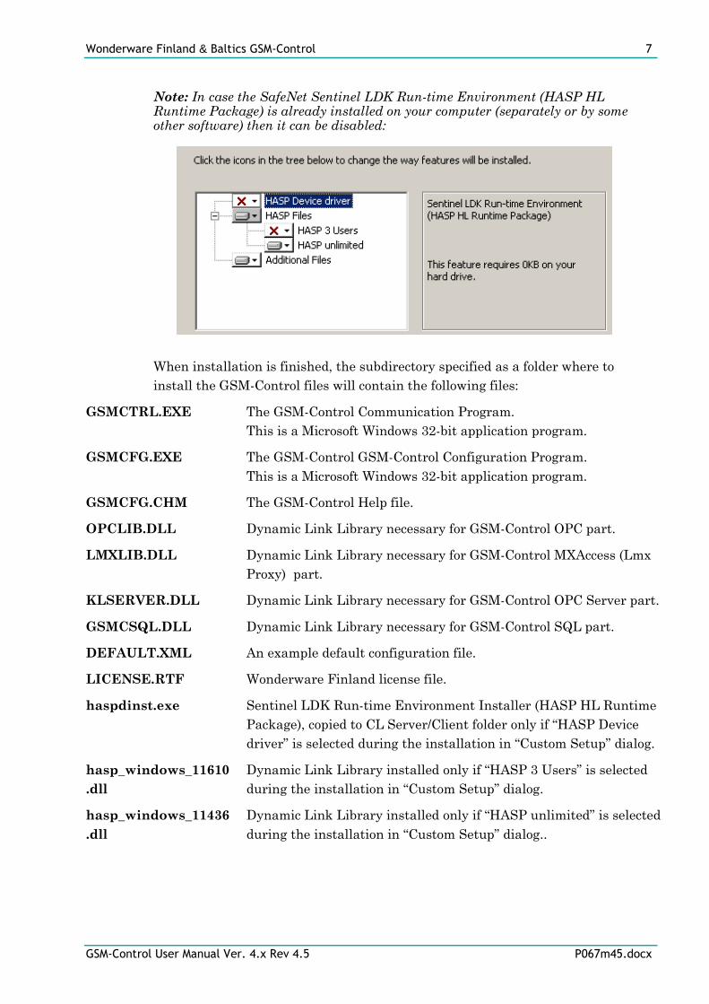
In case “HASP Device driver” and “HASP Files” (“HASP 3 Users”or “HASP
unlimited”) are selected then HASP USB key will be supported and both HASP-
key and software license will be available (files needed for HASP USB key will be
installed):
Wonderware Finland & Baltics GSM-Control 7
GSM-Control User Manual Ver. 4.x Rev 4.5 P067m45.docx
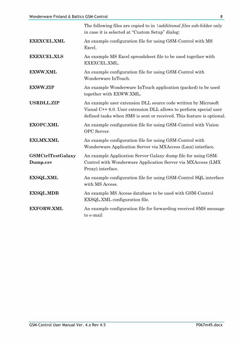
Note: In case the SafeNet Sentinel LDK Run-time Environment (HASP HL Runtime Package) is already installed on your computer (separately or by some other software) then it can be disabled:
When installation is finished, the subdirectory specified as a folder where to
install the GSM-Control files will contain the following files:
GSMCTRL.EXE The GSM-Control Communication Program.
This is a Microsoft Windows 32-bit application program.
GSMCFG.EXE The GSM-Control GSM-Control Configuration Program.
This is a Microsoft Windows 32-bit application program.
GSMCFG.CHM The GSM-Control Help file.
OPCLIB.DLL Dynamic Link Library necessary for GSM-Control OPC part.
LMXLIB.DLL Dynamic Link Library necessary for GSM-Control MXAccess (Lmx
Proxy) part.
KLSERVER.DLL Dynamic Link Library necessary for GSM-Control OPC Server part.
GSMCSQL.DLL Dynamic Link Library necessary for GSM-Control SQL part.
DEFAULT.XML An example default configuration file.
LICENSE.RTF Wonderware Finland license file.
haspdinst.exe Sentinel LDK Run-time Environment Installer (HASP HL Runtime
Package), copied to CL Server/Client folder only if “HASP Device
driver” is selected during the installation in “Custom Setup” dialog.
hasp_windows_11610
.dll
Dynamic Link Library installed only if “HASP 3 Users” is selected
during the installation in “Custom Setup” dialog.
hasp_windows_11436
.dll
Dynamic Link Library installed only if “HASP unlimited” is selected
during the installation in “Custom Setup” dialog..
Wonderware Finland & Baltics GSM-Control 8
GSM-Control User Manual Ver. 4.x Rev 4.5 P067m45.docx
The following files are copied to in \additional files sub-folder only
in case it is selected at “Custom Setup” dialog:
EXEXCEL.XML An example configuration file for using GSM-Control with MS
Excel.
EXEXCEL.XLS An example MS Excel spreadsheet file to be used together with
EXEXCEL.XML.
EXWW.XML An example configuration file for using GSM-Control with
Wonderware InTouch.
EXWW.ZIP An example Wonderware InTouch application (packed) to be used
together with EXWW.XML.
USRDLL.ZIP An example user extension DLL source code written by Microsoft
Visual C++ 6.0. User extension DLL allows to perform special user
defined tasks when SMS is sent or received. This feature is optional.
EXOPC.XML An example configuration file for using GSM-Control with Vision
OPC Server.
EXLMX.XML An example configuration file for using GSM-Control with
Wonderware Application Server via MXAccess (Lmx) interface.
GSMCtrlTestGalaxy
Dump.csv
An example Application Server Galaxy dump file for using GSM-
Control with Wonderware Application Server via MXAccess (LMX
Proxy) interface.
EXSQL.XML An example configuration file for using GSM-Control SQL interface
with MS Access.
EXSQL.MDB An example MS Access database to be used with GSM-Control
EXSQL.XML configuration file.
EXFORW.XML An example configuration file for forwarding received SMS message
to e-mail
Wonderware Finland & Baltics GSM-Control 9
GSM-Control User Manual Ver. 4.x Rev 4.5 P067m45.docx
The following files will be copied (only if same or newer versions are not yet there)
to MS Windows system directory (e.g. to C:\WINDOWS\SYSTEM32\) and if
necessary also will be automatically registered in the system:
OPCPROXY.DLL Proxy/stub DLL used for marshalling interfaces to local or remote
OPC Servers. This DLL is provided from OPC Foundation.
OPCENUM.EXE OPC Foundation OpcEnum Module necessary for OPC browsing.
Opc_aeps.dll OPC Foundation Alarms and Events Proxy.
Opcbc_ps.dll OPC Foundation Batch custom Proxy.
Opchda_ps.dll OPC Foundation Historical Data Access Proxy.
Opcsec_ps.dll OPC Foundation OPC Security Proxy.
OPCCOMN_PS.DLL
OPC Foundation Common Interfaces Proxy.
To uninstall the GSM-Control, start Control Panel, select “Uninstall a program”
(“Add/Remove Programs” on XP/2003) and select the “GSM-Control SMS
Gateway” from the list of available software products. Click on “Uninstall”
(“Add/Remove…” on XP/2003) and proceed as directed by the Uninstall Wizard.
Licensing by using HASP HL key
The following should be done to enable the licensing by HASP HL key:
1) The “HASP Device driver” and “HASP Files” (“HASP 3 Users”or “HASP
unlimited”) are selected during the GSM-Control installation in “Custom
Setup” dialog – that causes correspondingly haspdinst.exe and
hasp_windows_11610.dll or hasp_windows_114361.dll file are copied to GSM-
Control folder and Sentinel LDK Run-time Environment (HASP HL Runtime
Package) is installed and started, enabling the GSM-Control can detect the
HASP HL USB dongle;
2) insert the received HASP HL key into USB port, and wait until “Installing
device driver software” message disappears and “Device driver software
installed successfully” message appears;
3) start GSM-Control and check - if “Sofware key or HASP HL key not found!”
message does not appear then it means everything is done correctly and GSM-
Control runs in full mode with licensing by HASP HL key enabled.
Wonderware Finland & Baltics GSM-Control 10
GSM-Control User Manual Ver. 4.x Rev 4.5 P067m45.docx
Software license key
GSM-Control supports the “computer dependent” software licensing. The
following steps are required to enable it:
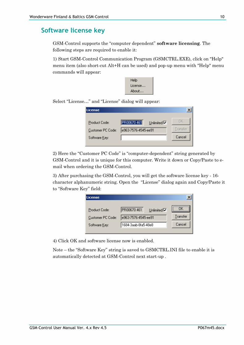
1) Start GSM-Control Communication Program (GSMCTRL.EXE), click on "Help"
menu item (also short-cut Alt+H can be used) and pop-up menu with "Help" menu
commands will appear:
Select “License…” and “License” dialog will appear:
2) Here the “Customer PC Code” is “computer-dependent” string generated by
GSM-Control and it is unique for this computer. Write it down or Copy/Paste to e-
mail when ordering the GSM-Control.
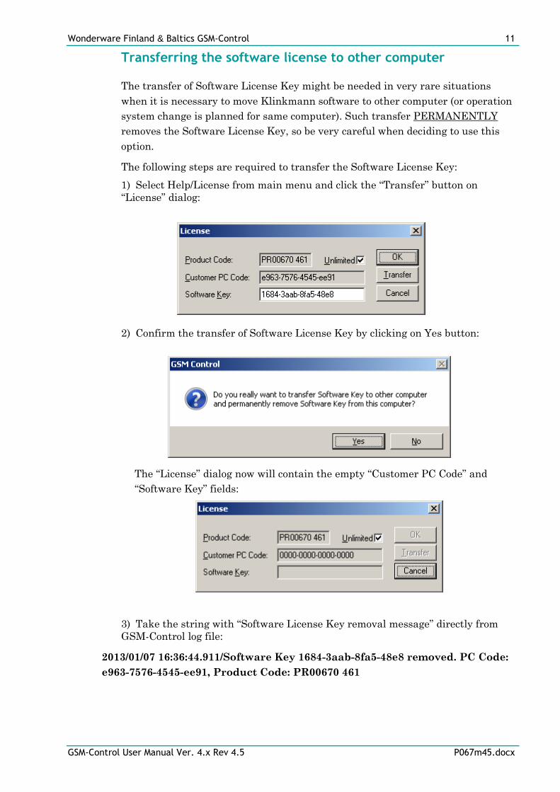
3) After purchasing the GSM-Control, you will get the software license key - 16-
character alphanumeric string. Open the “License” dialog again and Copy/Paste it
to “Software Key” field:
4) Click OK and software license now is enabled.
Note – the “Software Key” string is saved to GSMCTRL.INI file to enable it is
automatically detected at GSM-Control next start-up .
Wonderware Finland & Baltics GSM-Control 11
GSM-Control User Manual Ver. 4.x Rev 4.5 P067m45.docx
Transferring the software license to other computer
The transfer of Software License Key might be needed in very rare situations
when it is necessary to move Klinkmann software to other computer (or operation
system change is planned for same computer). Such transfer PERMANENTLY
removes the Software License Key, so be very careful when deciding to use this
option.
The following steps are required to transfer the Software License Key:
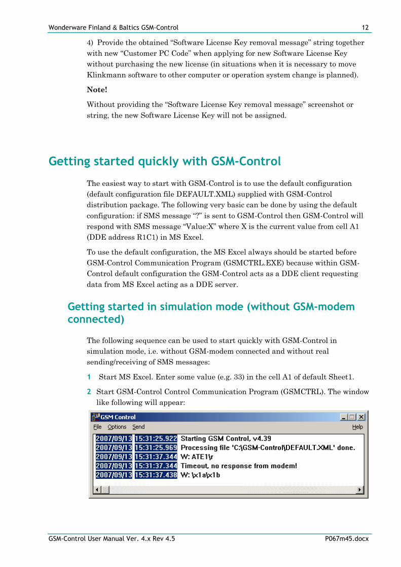
1) Select Help/License from main menu and click the “Transfer” button on
“License” dialog:
2) Confirm the transfer of Software License Key by clicking on Yes button:
The “License” dialog now will contain the empty “Customer PC Code” and
“Software Key” fields:
3) Take the string with “Software License Key removal message” directly from
GSM-Control log file:
2013/01/07 16:36:44.911/Software Key 1684-3aab-8fa5-48e8 removed. PC Code:
e963-7576-4545-ee91, Product Code: PR00670 461
Wonderware Finland & Baltics GSM-Control 12
GSM-Control User Manual Ver. 4.x Rev 4.5 P067m45.docx
4) Provide the obtained “Software License Key removal message” string together
with new “Customer PC Code” when applying for new Software License Key
without purchasing the new license (in situations when it is necessary to move
Klinkmann software to other computer or operation system change is planned).
Note!
Without providing the “Software License Key removal message” screenshot or
string, the new Software License Key will not be assigned.
Getting started quickly with GSM-Control
The easiest way to start with GSM-Control is to use the default configuration
(default configuration file DEFAULT.XML) supplied with GSM-Control
distribution package. The following very basic can be done by using the default
configuration: if SMS message “?” is sent to GSM-Control then GSM-Control will
respond with SMS message “Value:X” where X is the current value from cell A1
(DDE address R1C1) in MS Excel.
To use the default configuration, the MS Excel always should be started before
GSM-Control Communication Program (GSMCTRL.EXE) because within GSM-
Control default configuration the GSM-Control acts as a DDE client requesting
data from MS Excel acting as a DDE server.
Getting started in simulation mode (without GSM-modem connected)
The following sequence can be used to start quickly with GSM-Control in
simulation mode, i.e. without GSM-modem connected and without real
sending/receiving of SMS messages:
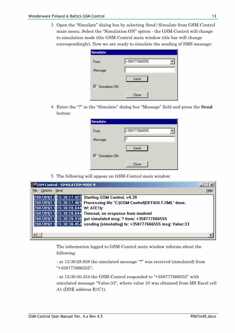
1 Start MS Excel. Enter some value (e.g. 33) in the cell A1 of default Sheet1.
2 Start GSM-Control Control Communication Program (GSMCTRL). The window
like following will appear:
Wonderware Finland & Baltics GSM-Control 13
GSM-Control User Manual Ver. 4.x Rev 4.5 P067m45.docx
3 Open the “Simulate” dialog box by selecting Send/Simulate from GSM-Control
main menu. Select the “Simulation ON” option - the GSM-Control will change
to simulation mode (the GSM-Control main window title bar will change
correspondingly). Now we are ready to simulate the sending of SMS message:
4 Enter the “?” in the “Simulate” dialog box “Message” field and press the Send
button:
5 The following will appear on GSM-Control main window:
The information logged to GSM-Control main window informs about the
following:
- at 15:30:28.938 the simulated message “?” was received (simulated) from
“+358777666555”;
- at 15:30:30.454 the GSM-Control responded to “+358777666555” with
simulated message “Value:33”, where value 33 was obtained from MS Excel cell
A1 (DDE address R1C1).
Wonderware Finland & Baltics GSM-Control 14
GSM-Control User Manual Ver. 4.x Rev 4.5 P067m45.docx
6 Now, if changing values in MS Excel, the receiving of new values can be
simulated by sending again simulated “?” from “Simulation” dialog box.
Getting started with GSM-modem connected
The following sequence to start quickly with GSM-Control by using GSM-modem
and sending/receiving of SMS messages by mobile phone:
1 Find out and remember the PIN code, phone number and GSM Messages
Service Center Number of the SIM card to be used with GSM-modem. The
GSM Messages Service Center Number can be found by inserting SIM card
into the mobile phone and selecting menu sequence like “Messages/Message
Setup/Service Center” or similarly.
2 Insert the SIM card into the GSM-modem. Connect GSM-modem to computer
serial port, e.g. to COM1 and power-up the GSM-modem. It is assumed the
GSM-modem has default serial port configuration: baud rate 19200, 8 data bits,
1 stop bit, no parity, no flow control. If GSM-modem settings differs from
default then it is necessary to restore the default settings - it can be done e.g. by
Windows HyperTerminal program by issuing AT&F (“Set all current parameters
to manufacturer defaults”) command.
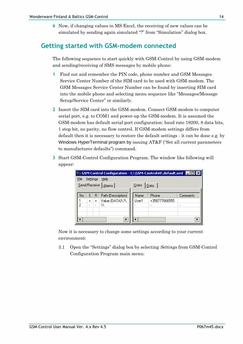
3 Start GSM-Control Configuration Program. The window like following will
appear:
Now it is necessary to change some settings according to your current
environment:
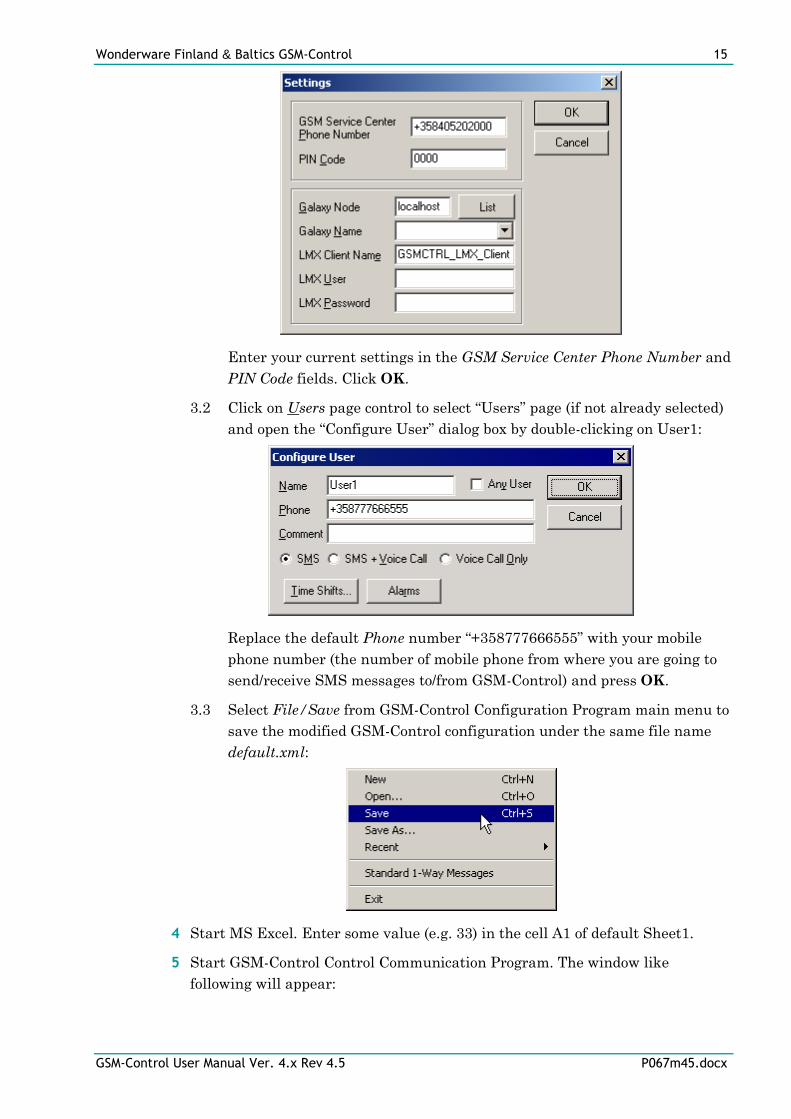
3.1 Open the “Settings” dialog box by selecting Settings from GSM-Control
Configuration Program main menu:
Wonderware Finland & Baltics GSM-Control 15
GSM-Control User Manual Ver. 4.x Rev 4.5 P067m45.docx
Enter your current settings in the GSM Service Center Phone Number and
PIN Code fields. Click OK.
3.2 Click on Users page control to select “Users” page (if not already selected)
and open the “Configure User” dialog box by double-clicking on User1:
Replace the default Phone number “+358777666555” with your mobile
phone number (the number of mobile phone from where you are going to
send/receive SMS messages to/from GSM-Control) and press OK.
3.3 Select File/Save from GSM-Control Configuration Program main menu to
save the modified GSM-Control configuration under the same file name
default.xml:
4 Start MS Excel. Enter some value (e.g. 33) in the cell A1 of default Sheet1.
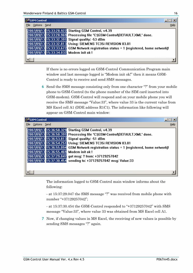
5 Start GSM-Control Control Communication Program. The window like
following will appear:
Wonderware Finland & Baltics GSM-Control 16
GSM-Control User Manual Ver. 4.x Rev 4.5 P067m45.docx
If there is no errors logged on GSM-Control Communication Program main
window and last message logged is “Modem init ok!” then it means GSM-
Control is ready to receive and send SMS messages.
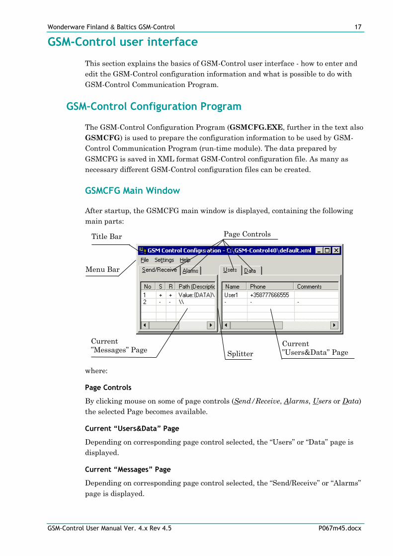
6 Send the SMS message consisting only from one character “?” from your mobile
phone to GSM-Control (to the phone number of the SIM card inserted into
GSM-modem). GSM-Control will respond and on your mobile phone you will
receive the SMS message “Value:33”, where value 33 is the current value from
MS Excel cell A1 (DDE address R1C1). The information like following will
appear on GSM-Control main window:
The information logged to GSM-Control main window informs about the
following:
- at 15:37:29.047 the SMS message “?” was received from mobile phone with
number “+37129257042”;
- at 15:37:30.454 the GSM-Control responded to “+37129257042” with SMS
message “Value:33”, where value 33 was obtained from MS Excel cell A1.
7 Now, if changing values in MS Excel, the receiving of new values is possible by
sending SMS messages “?” again.
Wonderware Finland & Baltics GSM-Control 17
GSM-Control User Manual Ver. 4.x Rev 4.5 P067m45.docx
GSM-Control user interface
This section explains the basics of GSM-Control user interface - how to enter and
edit the GSM-Control configuration information and what is possible to do with
GSM-Control Communication Program.
GSM-Control Configuration Program
The GSM-Control Configuration Program (GSMCFG.EXE, further in the text also
GSMCFG) is used to prepare the configuration information to be used by GSM-
Control Communication Program (run-time module). The data prepared by
GSMCFG is saved in XML format GSM-Control configuration file. As many as
necessary different GSM-Control configuration files can be created.
GSMCFG Main Window
After startup, the GSMCFG main window is displayed, containing the following
main parts:
where:
Page Controls
By clicking mouse on some of page controls (Send/Receive, Alarms, Users or Data)
the selected Page becomes available.
Current “Users&Data” Page
Depending on corresponding page control selected, the “Users” or “Data” page is
displayed.
Current “Messages” Page
Depending on corresponding page control selected, the “Send/Receive” or “Alarms”
page is displayed.
Title Bar
Menu Bar
Current
”Messages” Page Splitter
Current
”Users&Data” Page
Page Controls
Wonderware Finland & Baltics GSM-Control 18
GSM-Control User Manual Ver. 4.x Rev 4.5 P067m45.docx
Splitter
Used to change the horizontal proportion between current “Users&Data” page and
current “Messages” page - by clicking the mouse left button on the Splitter bar
(separator of pages) and dragging (moving the mouse without releasing the left
button).
Menu Bar
Contains the following Main Menu selections: “File”, “Settings” and “Help”.
Title Bar
Contains the path to currently opened GSM-Control configuration file or in
simulation mode changes to “SIMULATION MODE !!!!”.
Editing data in ”Users&Data” and ”Messages” Pages
There are common rules how to edit information in “Users”, “Data”,
“Send/Receive” and “Alarms” pages.
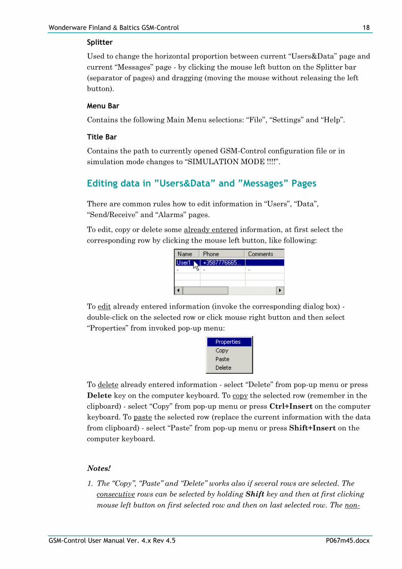
To edit, copy or delete some already entered information, at first select the
corresponding row by clicking the mouse left button, like following:
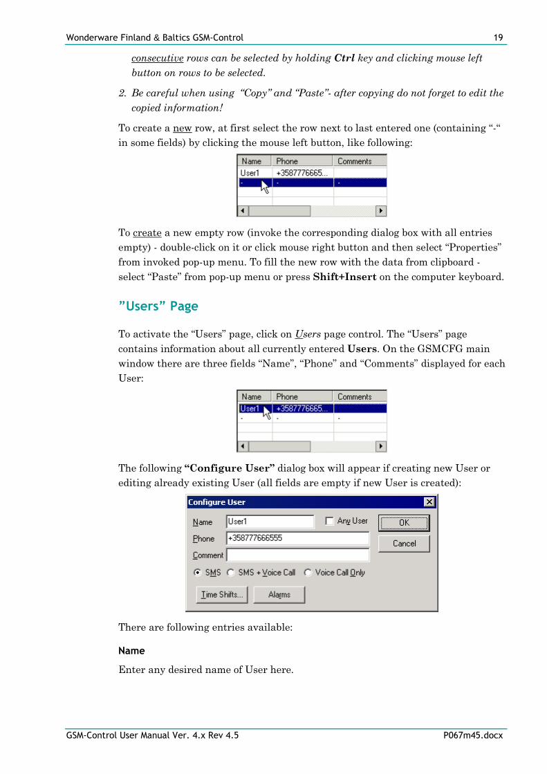
To edit already entered information (invoke the corresponding dialog box) -
double-click on the selected row or click mouse right button and then select
“Properties” from invoked pop-up menu:
To delete already entered information - select “Delete” from pop-up menu or press
Delete key on the computer keyboard. To copy the selected row (remember in the
clipboard) - select “Copy” from pop-up menu or press Ctrl+Insert on the computer
keyboard. To paste the selected row (replace the current information with the data
from clipboard) - select “Paste” from pop-up menu or press Shift+Insert on the
computer keyboard.
Notes!
1. The “Copy”, “Paste” and “Delete” works also if several rows are selected. The
consecutive rows can be selected by holding Shift key and then at first clicking
mouse left button on first selected row and then on last selected row. The non-
Wonderware Finland & Baltics GSM-Control 19
GSM-Control User Manual Ver. 4.x Rev 4.5 P067m45.docx
consecutive rows can be selected by holding Ctrl key and clicking mouse left
button on rows to be selected.
2. Be careful when using “Copy” and “Paste”- after copying do not forget to edit the
copied information!
To create a new row, at first select the row next to last entered one (containing “-“
in some fields) by clicking the mouse left button, like following:
To create a new empty row (invoke the corresponding dialog box with all entries
empty) - double-click on it or click mouse right button and then select “Properties”
from invoked pop-up menu. To fill the new row with the data from clipboard -
select “Paste” from pop-up menu or press Shift+Insert on the computer keyboard.
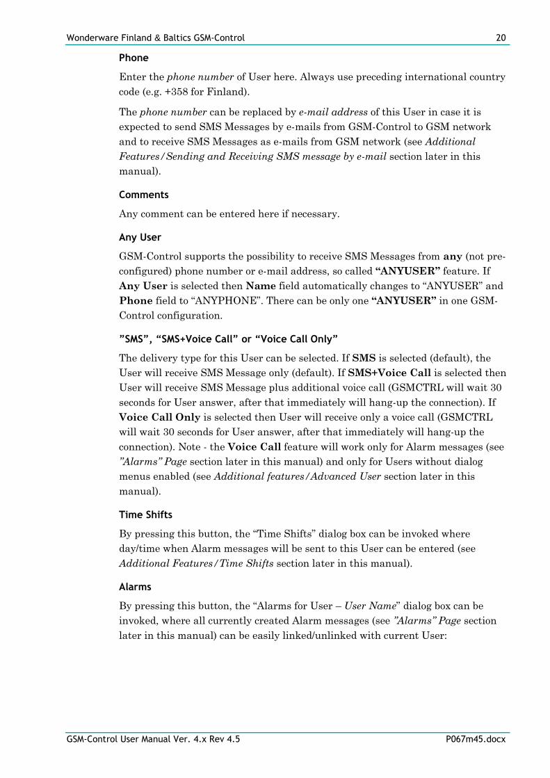
”Users” Page
To activate the “Users” page, click on Users page control. The “Users” page
contains information about all currently entered Users. On the GSMCFG main
window there are three fields “Name”, “Phone” and “Comments” displayed for each
User:
The following “Configure User” dialog box will appear if creating new User or
editing already existing User (all fields are empty if new User is created):
There are following entries available:
Name
Enter any desired name of User here.
Wonderware Finland & Baltics GSM-Control 20
GSM-Control User Manual Ver. 4.x Rev 4.5 P067m45.docx
Phone
Enter the phone number of User here. Always use preceding international country
code (e.g. +358 for Finland).
The phone number can be replaced by e-mail address of this User in case it is
expected to send SMS Messages by e-mails from GSM-Control to GSM network
and to receive SMS Messages as e-mails from GSM network (see Additional
Features/Sending and Receiving SMS message by e-mail section later in this
manual).
Comments
Any comment can be entered here if necessary.
Any User
GSM-Control supports the possibility to receive SMS Messages from any (not pre-
configured) phone number or e-mail address, so called “ANYUSER” feature. If
Any User is selected then Name field automatically changes to “ANYUSER” and
Phone field to “ANYPHONE”. There can be only one “ANYUSER” in one GSM-
Control configuration.
”SMS”, “SMS+Voice Call” or “Voice Call Only”
The delivery type for this User can be selected. If SMS is selected (default), the
User will receive SMS Message only (default). If SMS+Voice Call is selected then
User will receive SMS Message plus additional voice call (GSMCTRL will wait 30
seconds for User answer, after that immediately will hang-up the connection). If
Voice Call Only is selected then User will receive only a voice call (GSMCTRL
will wait 30 seconds for User answer, after that immediately will hang-up the
connection). Note - the Voice Call feature will work only for Alarm messages (see
”Alarms” Page section later in this manual) and only for Users without dialog
menus enabled (see Additional features/Advanced User section later in this
manual).
Time Shifts
By pressing this button, the “Time Shifts” dialog box can be invoked where
day/time when Alarm messages will be sent to this User can be entered (see
Additional Features/Time Shifts section later in this manual).
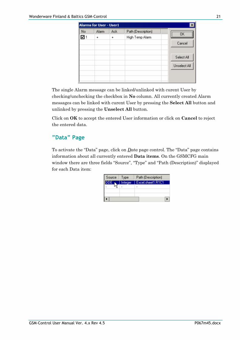
Alarms
By pressing this button, the “Alarms for User – User Name” dialog box can be
invoked, where all currently created Alarm messages (see ”Alarms” Page section
later in this manual) can be easily linked/unlinked with current User:
Wonderware Finland & Baltics GSM-Control 21
GSM-Control User Manual Ver. 4.x Rev 4.5 P067m45.docx
The single Alarm message can be linked/unlinked with curent User by
checking/unchecking the checkbox in No column. All currently created Alarm
messages can be linked with curent User by pressing the Select All button and
unlinked by pressing the Unselect All button.
Click on OK to accept the entered User information or click on Cancel to reject
the entered data.
”Data” Page
To activate the “Data” page, click on Data page control. The “Data” page contains
information about all currently entered Data items. On the GSMCFG main
window there are three fields “Source”, “Type” and “Path (Description)” displayed
for each Data item:
Wonderware Finland & Baltics GSM-Control 22
GSM-Control User Manual Ver. 4.x Rev 4.5 P067m45.docx
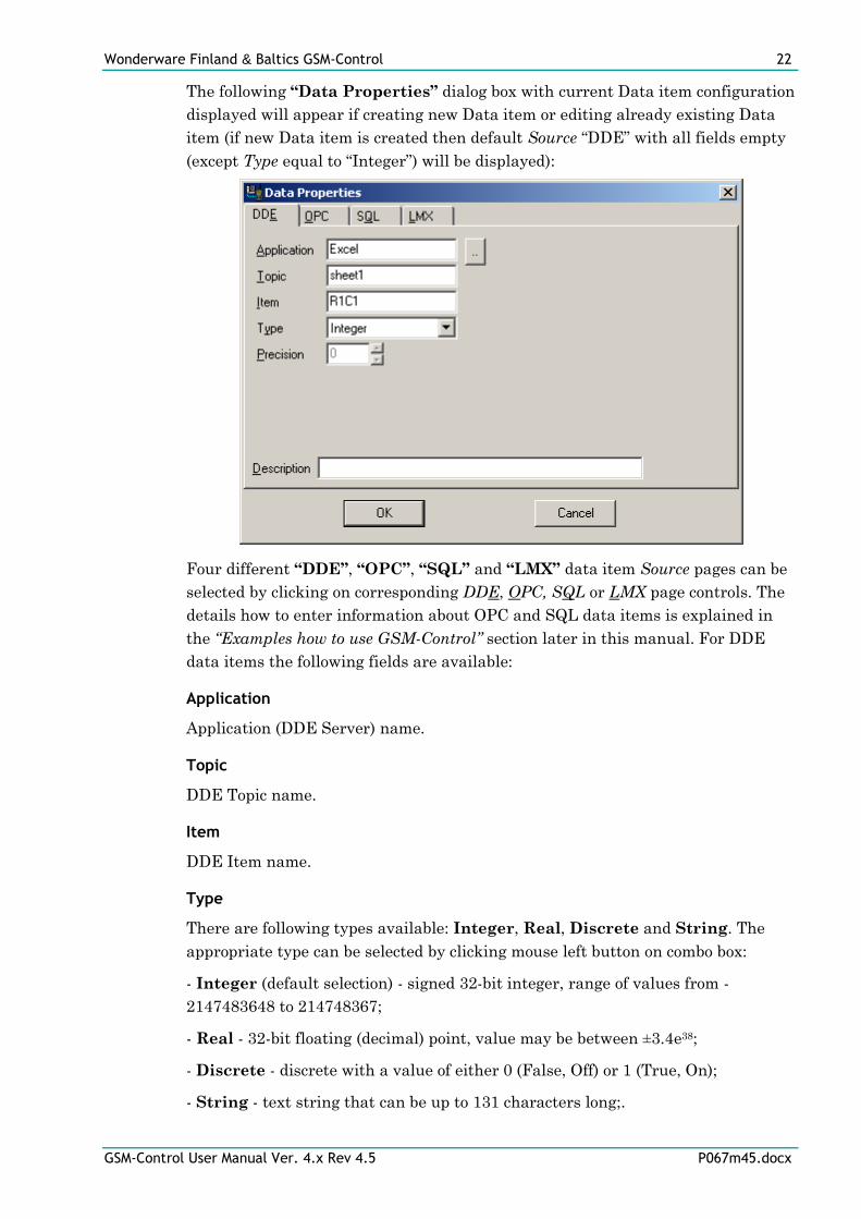
The following “Data Properties” dialog box with current Data item configuration
displayed will appear if creating new Data item or editing already existing Data
item (if new Data item is created then default Source “DDE” with all fields empty
(except Type equal to “Integer”) will be displayed):
Four different “DDE”, “OPC”, “SQL” and “LMX” data item Source pages can be
selected by clicking on corresponding DDE, OPC, SQL or LMX page controls. The
details how to enter information about OPC and SQL data items is explained in
the “Examples how to use GSM-Control” section later in this manual. For DDE
data items the following fields are available:
Application
Application (DDE Server) name.
Topic
DDE Topic name.
Item
DDE Item name.
Type
There are following types available: Integer, Real, Discrete and String. The
appropriate type can be selected by clicking mouse left button on combo box:
- Integer (default selection) - signed 32-bit integer, range of values from -
2147483648 to 214748367;
- Real - 32-bit floating (decimal) point, value may be between ±3.4e38;
- Discrete - discrete with a value of either 0 (False, Off) or 1 (True, On);
- String - text string that can be up to 131 characters long;.
Wonderware Finland & Baltics GSM-Control 23
GSM-Control User Manual Ver. 4.x Rev 4.5 P067m45.docx
Precision
This field is accessible only for Real and String types:
- if Type is Real then Precision field is used to enter the number of digits after
decimal point. The default Precision is 0;
- if Type is String then Precision field is used to enter the maximum length of
string.
The Type and Precision fields are used to format the values of Data items in Send
and Alarm messages to be sent from GSM-Control. For example, if Type Real and
Precision 1 is used then following values will be sent from GSM-Control depending
on actual value, for example:
- if actual value is 24.7 then SMS message sent from GSM-Control will contain
“24.7”;
- if actual value is 24.74 then SMS message sent from GSM-Control will contain
“24.7”;
- if actual value is 24.75 then SMS message sent from GSM-Control will contain
“24.8”;
- if actual value is 24 then SMS message sent from GSM-Control will contain
“24.0”.
Description
This field is common for all data item Source pages and any desired description of
data item can be entered here and correspondingly it will be displayed on
GSMCFG main window “Data” page “Path (Description)” field for this Data item.
If Description field is empty then on GSMCFG main window “Data” page this
Data item “Path (Description)” field will be filled with Path, which depends on
Data item current configuration (for example, for DDE items it will be as
application.topic.item).
Click on OK to accept the entered User information or click on Cancel to reject
the entered data.
”Send/Receive” Page
To activate the “Send/Receive” page, click on Send/Receive page control. The
“Send/Receive” page contains information about all currently entered Send and
Receive messages - SMS Messages to be sent from GSM-Control to remote GSM
operator or device are called Send messages and SMS messages which can be
received by GSM-Control from remote GSM operator or device are called Receive
messages. All Send and Receive messages are grouped in the pairs consisting of:
1 both Send message and Receive message - in this case GSM-Control after
receiving this Receive message will respond with this Send message;
Wonderware Finland & Baltics GSM-Control 24
GSM-Control User Manual Ver. 4.x Rev 4.5 P067m45.docx
2 only Send message - the sending of this message can be done via DDE or OPC;
3 only Receive message - no response message will be sent.
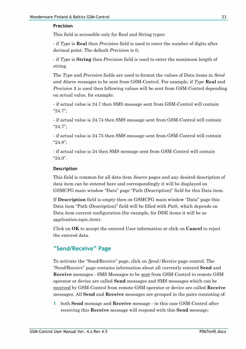
On the GSMCFG main window there are four fields “No“, “S”, “R” and “Path
(Description)” displayed for each row (pair) of Send/Receive messages:
where:
No - the number of Send/Receive message; this number is created/updated
automatically when new Send/Receive message pair is created or some existing
one deleted;
S - sign “+” indicates the Send message exists; sign “-” indicates the Send
message does not exist;
R - sign “+” indicates the Receive message exists; sign “-” indicates the Receive
message does not exist;
Path (Description) - the contents of Send/Receive message or additionally
entered description of this Send/Receive message pair.
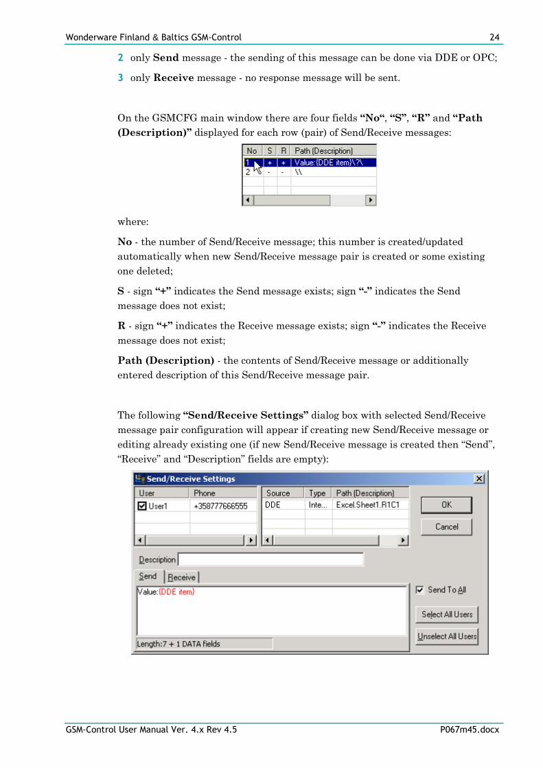
The following “Send/Receive Settings” dialog box with selected Send/Receive
message pair configuration will appear if creating new Send/Receive message or
editing already existing one (if new Send/Receive message is created then “Send”,
“Receive” and “Description” fields are empty):
Wonderware Finland & Baltics GSM-Control 25
GSM-Control User Manual Ver. 4.x Rev 4.5 P067m45.docx
Contents of Send/Receive messages
The “Send” or “Receive” message pages (fields where to enter the text of message
and locate the Data items) can be selected by clicking on corresponding Send or
Receive page controls. The information in “Send” or “Receive” message fields can
be entered the following way:
- the text can be entered directly by locating cursor on necessary Send or Receive
message position (by clicking mouse left button); the entered text appears in
black color; in Send message - this text will not change in the SMS message sent
from GSM-Control; in Receive message - this text will be used to process the
received SMS message;
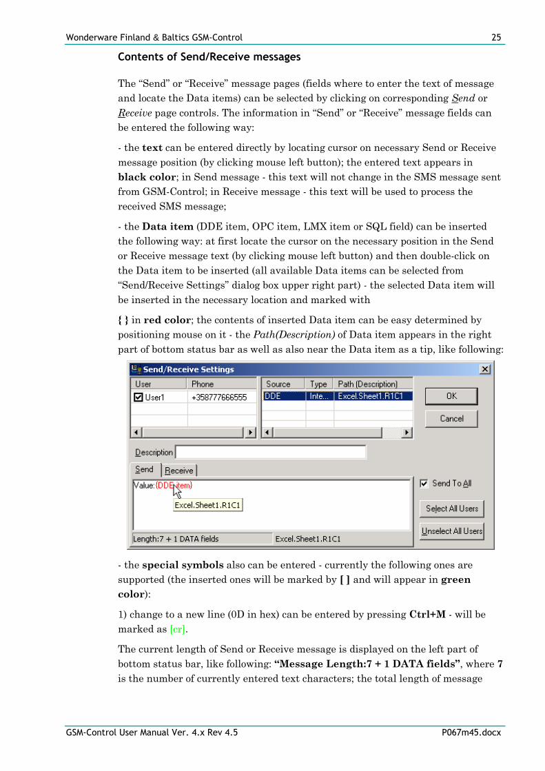
- the Data item (DDE item, OPC item, LMX item or SQL field) can be inserted
the following way: at first locate the cursor on the necessary position in the Send
or Receive message text (by clicking mouse left button) and then double-click on
the Data item to be inserted (all available Data items can be selected from
“Send/Receive Settings” dialog box upper right part) - the selected Data item will
be inserted in the necessary location and marked with
{ } in red color; the contents of inserted Data item can be easy determined by
positioning mouse on it - the Path(Description) of Data item appears in the right
part of bottom status bar as well as also near the Data item as a tip, like following:
- the special symbols also can be entered - currently the following ones are
supported (the inserted ones will be marked by [ ] and will appear in green
color):
1) change to a new line (0D in hex) can be entered by pressing Ctrl+M - will be
marked as [cr].
The current length of Send or Receive message is displayed on the left part of
bottom status bar, like following: “Message Length:7 + 1 DATA fields”, where 7
is the number of currently entered text characters; the total length of message
Wonderware Finland & Baltics GSM-Control 26
GSM-Control User Manual Ver. 4.x Rev 4.5 P067m45.docx
cannot be exactly determined if there presents at least one Data item (the length
of DATA fields is not fixed and depends on current values).
Important Notes!!!
1. To simplify the recognition of Receive messages, GSM-Control Communication
Program (GSMCTRL) checks for matching (for all Receive messages configured
for User with phone number matching with sender phone number) the received
SMS message’s text only till the first Data item (DDE item, OPC item, LMX
item or SQL field) inserted, therefore it is important to configure unique first text
parts for User all Receive messages. For example, the following configuration of
Receive messages: “N:{DDE item}” and “N:{DDE item}P:{ DDE item}” is
incorrect - GSM-Control cannot recognize the difference if receiving these SMS
messages.
2. The processing of received SMS messages is case insensitive, so GSM-Control
will not recognize the difference, for example, between following SMS messages
received: “N:{DDE item}” and “n:{DDE item}”.
Linking Users with Send/Receive messages
Each Send/Receive message pair should be linked with at least one User. This can
be done by selecting (checking the checkbox before User name) one or several
Users from “Send/Receive Settings” dialog box upper left part. The “Select All
Users” and “Unselect All Users” buttons can be used to correspondingly
select/unselect all Users currently linked with this Send/Receive message pair.
The Send and Receive Users may be different. The selected Receive Users have
permission to send configured message to GSM-Control, but unselected Receive
Users do not have such permission. The Send Users will receive configured Send
message form GSM-Control, after receiving corresponding Receive message from
one of selected Users. If Send To All checkbox is checked (by default), then all
selected Send Users will receive configured Send message. If Send To All
checkbox is unchecked, then configured Send message will be send only to User
who sent the Receive message, if such User or ANYUSER is selected as a Send
User.
Note!
If ANYUSER is selected both for Send and Receive messages then Receive message
can be received from any (not included in GSM-Control current configuration)
phone number and Send message will be replied to sender’s phone number.
Click on OK to accept the entered Send/Receive message information or click on
Cancel to reject the entered data.
Wonderware Finland & Baltics GSM-Control 27
GSM-Control User Manual Ver. 4.x Rev 4.5 P067m45.docx
”Alarms” Page
To activate the “Alarms” page, click on Alarms page control. The “Alarms” page
contains information about all currently entered Alarm and Alarm
Acknowledgment messages - SMS Messages to be sent from GSM-Control to
remote GSM operator or device when some alarm/event occurs are called Alarm
messages and SMS messages which can be received by GSM-Control as an alarm
acknowledgment are called Alarm Acknowledgment (further Ack) messages.
The Ack messages are optional and can be used if it is necessary to receive the
confirmation of Alarm message successful delivery .
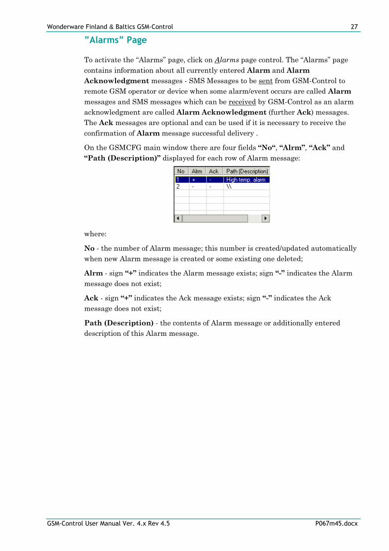
On the GSMCFG main window there are four fields “No“, “Alrm”, “Ack” and
“Path (Description)” displayed for each row of Alarm message:
where:
No - the number of Alarm message; this number is created/updated automatically
when new Alarm message is created or some existing one deleted;
Alrm - sign “+” indicates the Alarm message exists; sign “-” indicates the Alarm
message does not exist;
Ack - sign “+” indicates the Ack message exists; sign “-” indicates the Ack
message does not exist;
Path (Description) - the contents of Alarm message or additionally entered
description of this Alarm message.
Wonderware Finland & Baltics GSM-Control 28
GSM-Control User Manual Ver. 4.x Rev 4.5 P067m45.docx
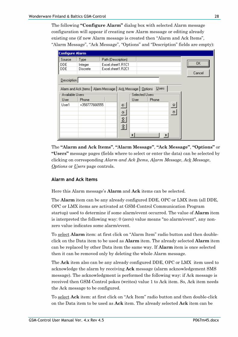
The following “Configure Alarm” dialog box with selected Alarm message
configuration will appear if creating new Alarm message or editing already
existing one (if new Alarm message is created then “Alarm and Ack Items”,
“Alarm Message”, “Ack Message”, “Options” and “Description” fields are empty):
The “Alarm and Ack Items”, “Alarm Message”, “Ack Message”, “Options” or
“Users” message pages (fields where to select or enter the data) can be selected by
clicking on corresponding Alarm and Ack Items, Alarm Message, Ack Message,
Options or Users page controls.
Alarm and Ack Items
Here this Alarm message’s Alarm and Ack items can be selected.
The Alarm item can be any already configured DDE, OPC or LMX item (all DDE,
OPC or LMX items are activated at GSM-Control Communication Program
startup) used to determine if some alarm/event occurred. The value of Alarm item
is interpreted the following way: 0 (zero) value means "no alarm/event", any non-
zero value indicates some alarm/event.
To select Alarm item: at first click on “Alarm Item” radio button and then double-
click on the Data item to be used as Alarm item. The already selected Alarm item
can be replaced by other Data item the same way. If Alarm item is once selected
then it can be removed only by deleting the whole Alarm message.
The Ack item also can be any already configured DDE, OPC or LMX item used to
acknowledge the alarm by receiving Ack message (alarm acknowledgement SMS
message). The acknowledgment is performed the following way: if Ack message is
received then GSM-Control pokes (writes) value 1 to Ack item. So, Ack item needs
the Ack message to be configured.
To select Ack item: at first click on “Ack Item” radio button and then double-click
on the Data item to be used as Ack item. The already selected Ack item can be
Wonderware Finland & Baltics GSM-Control 29
GSM-Control User Manual Ver. 4.x Rev 4.5 P067m45.docx
replaced by other Data item the same way. To remove Ack item, click on Clear
Alarm Item button.
Alarm Message and Ack Message
Here the texts of Alarm Message and Ack Message can be entered as well as if
necessary also Data items (DDE item, OPC item, LMX item or SQL field) can be
inserted. The entering/editing contents of Alarm Message and Ack Message is
completely same as Send/Receive messages - refer to “Send/Receive” Page section
upper in this manual.
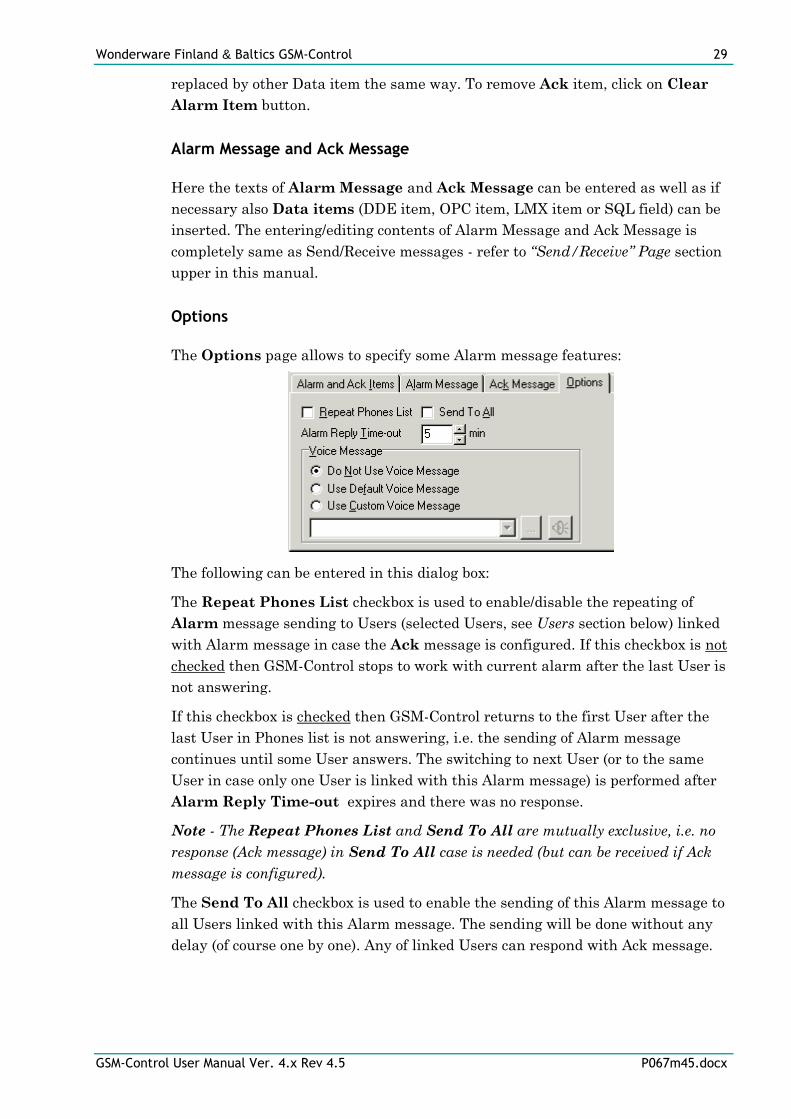
Options
The Options page allows to specify some Alarm message features:
The following can be entered in this dialog box:
The Repeat Phones List checkbox is used to enable/disable the repeating of
Alarm message sending to Users (selected Users, see Users section below) linked
with Alarm message in case the Ack message is configured. If this checkbox is not
checked then GSM-Control stops to work with current alarm after the last User is
not answering.
If this checkbox is checked then GSM-Control returns to the first User after the
last User in Phones list is not answering, i.e. the sending of Alarm message
continues until some User answers. The switching to next User (or to the same
User in case only one User is linked with this Alarm message) is performed after
Alarm Reply Time-out expires and there was no response.
Note - The Repeat Phones List and Send To All are mutually exclusive, i.e. no
response (Ack message) in Send To All case is needed (but can be received if Ack
message is configured).
The Send To All checkbox is used to enable the sending of this Alarm message to
all Users linked with this Alarm message. The sending will be done without any
delay (of course one by one). Any of linked Users can respond with Ack message.
Wonderware Finland & Baltics GSM-Control 30
GSM-Control User Manual Ver. 4.x Rev 4.5 P067m45.docx
The Voice Message feature enables the processing of alternative (voice) call in
case the GSM SMS Service becomes inaccessible. The following three selections
are possible:
“Do Not Use Voice Message”
This is default selection. In this case no alternative (voice) call will be performed
for this Alarm message.
“Use Default Voice Message”
In this case the default Voice Message processing will be performed for this Alarm
message, i.e. the GSMCTRL.INI file WAVFile= setting will be used to obtain the
name of sound file (.WAV) containing pre-recorded voice message and
WAVSendRetries= setting will be used as number of voice call retries before
rejecting the voice calls (see also Additional features/GSMCTRL.INI file/ Entries
for alternative (voice) call support in case SMS Service not available section later
in this manual.
“Use Custom Voice Message”
In this case the sound file (.WAV) for this Alarm message can be selected from
combo box, i.e. the Alarm message can be associated with unique sound file
containing pre-recorded voice message. The GSMCTRL.INI file
WAVSendRetries= setting still will be used as number of voice call retries before
rejecting the voice calls.
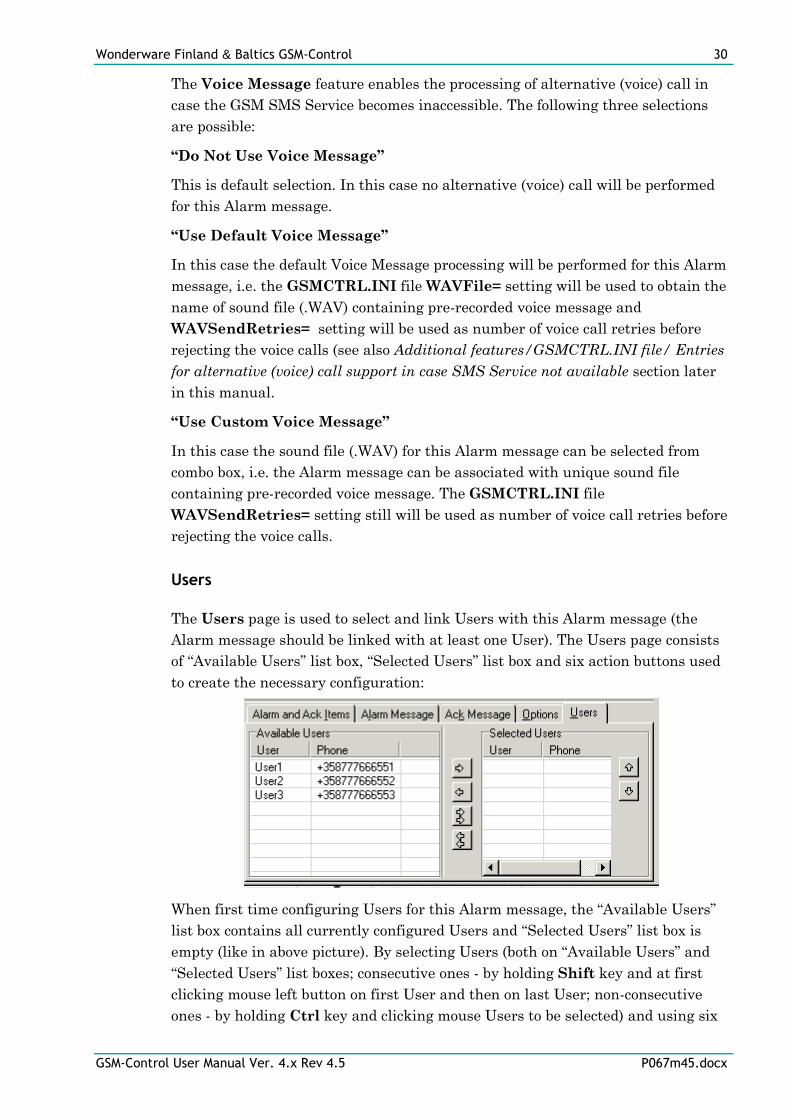
Users
The Users page is used to select and link Users with this Alarm message (the
Alarm message should be linked with at least one User). The Users page consists
of “Available Users” list box, “Selected Users” list box and six action buttons used
to create the necessary configuration:
When first time configuring Users for this Alarm message, the “Available Users”
list box contains all currently configured Users and “Selected Users” list box is
empty (like in above picture). By selecting Users (both on “Available Users” and
“Selected Users” list boxes; consecutive ones - by holding Shift key and at first
clicking mouse left button on first User and then on last User; non-consecutive
ones - by holding Ctrl key and clicking mouse Users to be selected) and using six
Wonderware Finland & Baltics GSM-Control 31
GSM-Control User Manual Ver. 4.x Rev 4.5 P067m45.docx
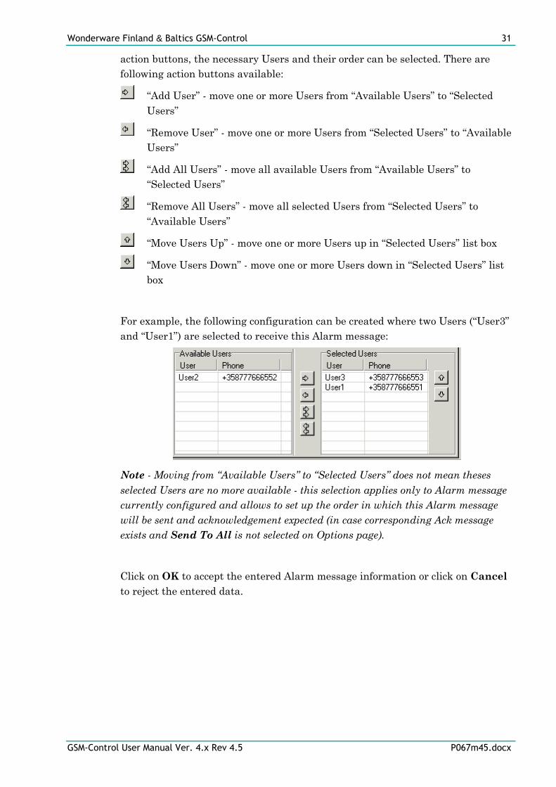
action buttons, the necessary Users and their order can be selected. There are
following action buttons available:
“Add User” - move one or more Users from “Available Users” to “Selected
Users”
“Remove User” - move one or more Users from “Selected Users” to “Available
Users”
“Add All Users” - move all available Users from “Available Users” to
“Selected Users”
“Remove All Users” - move all selected Users from “Selected Users” to
“Available Users”
“Move Users Up” - move one or more Users up in “Selected Users” list box
“Move Users Down” - move one or more Users down in “Selected Users” list
box
For example, the following configuration can be created where two Users (“User3”
and “User1”) are selected to receive this Alarm message:
Note - Moving from “Available Users” to “Selected Users” does not mean theses
selected Users are no more available - this selection applies only to Alarm message
currently configured and allows to set up the order in which this Alarm message
will be sent and acknowledgement expected (in case corresponding Ack message
exists and Send To All is not selected on Options page).
Click on OK to accept the entered Alarm message information or click on Cancel
to reject the entered data.
Wonderware Finland & Baltics GSM-Control 32
GSM-Control User Manual Ver. 4.x Rev 4.5 P067m45.docx
GSMCFG Main Menu
The following top-level menu items and corresponding pop-up menus are used.
File
To access the "File" menu commands, click on "File" menu item (also short-cut
Alt+F can be used) and pop-up menu with "File" menu commands will appear:
The "File" menu commands are used to process GSM-Control configuration file(s).
There are following commands available:
New
The "New" command is used to start the creation of new GSM-Control
configuration. The "New" command automatically invokes the "Settings" dialog
box (see below). The "New" command also can be invoked by using short-cut
Ctrl+N.
Open
The "Open" command is used to open existing GSM-Control configuration file. By
default the GSM-Control configuration file has the file name extension .XML (e.g.
CONFIG1.XML), but also any other file name extension can be used. This
command also can be invoked by using short-cut Ctrl+O.
Save
The "Save" command can be used to save the current GSM-Control configuration
in the current GSM-Control configuration file. This command also can be invoked
by using short-cut Ctrl+S.
Save As...
The "Save As..." command can be used to save the current GSM-Control
configuration in the different (not current) GSM-Control configuration file.
Recent
The "Recent " command can be used to open some recently used GSM-Control
configuration file.
Wonderware Finland & Baltics GSM-Control 33
GSM-Control User Manual Ver. 4.x Rev 4.5 P067m45.docx
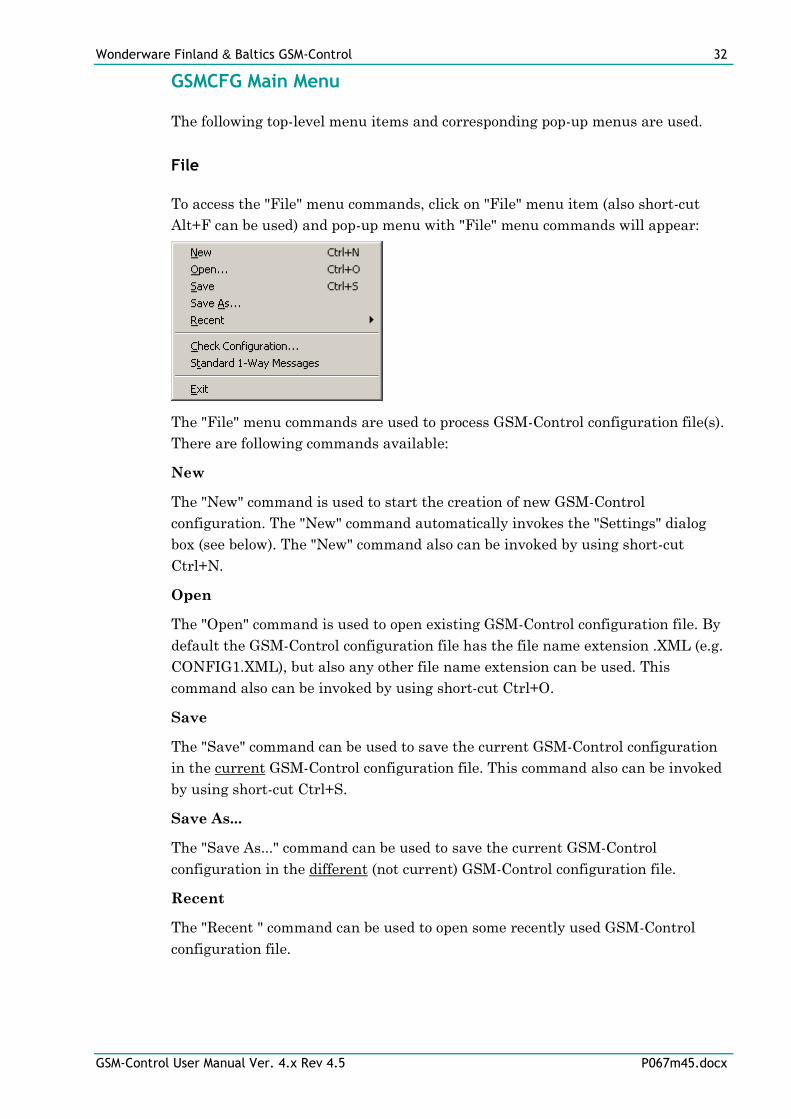
Check Configuration…
The “Check Configuration” can be used to check configuration on logic errors. The
command displays “Error items” dialog box:
If errors found, then items with errors are displayed, and items can be edited
directly from this dialog box, by clicking on Edit button, or deleted by clicking
Delete button. When error fixed, you can press Refresh button to search errors
again.
Standard 1-Way Messages
This command invokes the “One Way Messages” dialog box, see the Additional
features/One direction sending of SMS messages from GSM-Control/Sending “1-
way” Messages section later in this manual.
Exit
The "Exit" command can be used to exit from GSM-Control Configuration
Program.
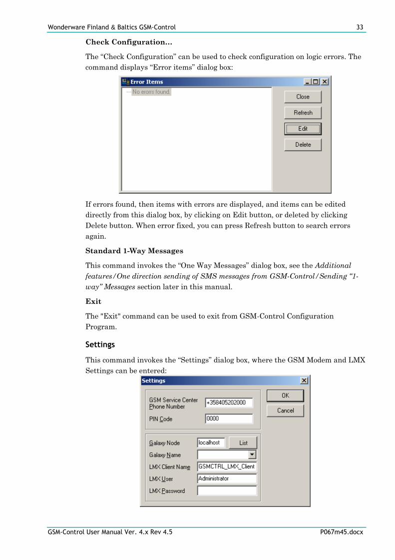
Settings
This command invokes the “Settings” dialog box, where the GSM Modem and LMX
Settings can be entered:
Wonderware Finland & Baltics GSM-Control 34
GSM-Control User Manual Ver. 4.x Rev 4.5 P067m45.docx
The GSM Service Center Phone Number and PIN Code are necessary
parameters to initiate the data exchange with GSM-modem connected to the
computer's serial port. The GSM Service Center Phone Number and PIN
Code are unique for each configuration, i.e. each GSM-Control configuration file
contains one common GSM Service Center Phone Number and one Pin Code.
Note: The GSM Service Center Phone Number can be changed at GSM-Control
Communication Program (GSMCTRL.EXE) runtime by using the reserved DDE or
OPC item SERVICE_NUMBER (see Additional features/Sending messages by
using DDE or OPC section later in this manual).
The Galaxy Node, Galaxy Name, LMX Client Name, LMX User and LMX
Password are parameters which describe the LMX data source - used for
connection to Wonderware Application Server Galaxy via MXAccess (LMX Proxy):
Galaxy Node and Galaxy Name parameters are used only by GSMCFG to
browse Galaxy items. Galaxy Node specifies the Galaxy repository node, Galaxy
Name is the name of Galaxy. Those parameters are not used by GSMCTRL
because only one galaxy can be deployed at the time and GSMCTRL must run on
the one of Application Server Galaxy nodes in purpose to access the LMX data.
The pressing of List button enumerates galaxies for Galaxy Node and fills the
Galaxy Name combo box.
LMX Client Name parameter can be any unique string. This parameter
identifies LMX connection to the Application Server and is used internally by
Application Server.
LMX User and LMX Password parameters specify the username and password
of GSMCCTRL connection, in case the security is enabled on the Galaxy.
Help
To access the "Help" menu commands, click on "Help" menu item (also short-cut
Alt+H can be used) and pop-up menu with "Help" menu commands will appear:
There are following "Help" menu commands available:
About…
This command can be used to display the general information about GSM-Control
Configuration Program.
Wonderware Finland & Baltics GSM-Control 35
GSM-Control User Manual Ver. 4.x Rev 4.5 P067m45.docx
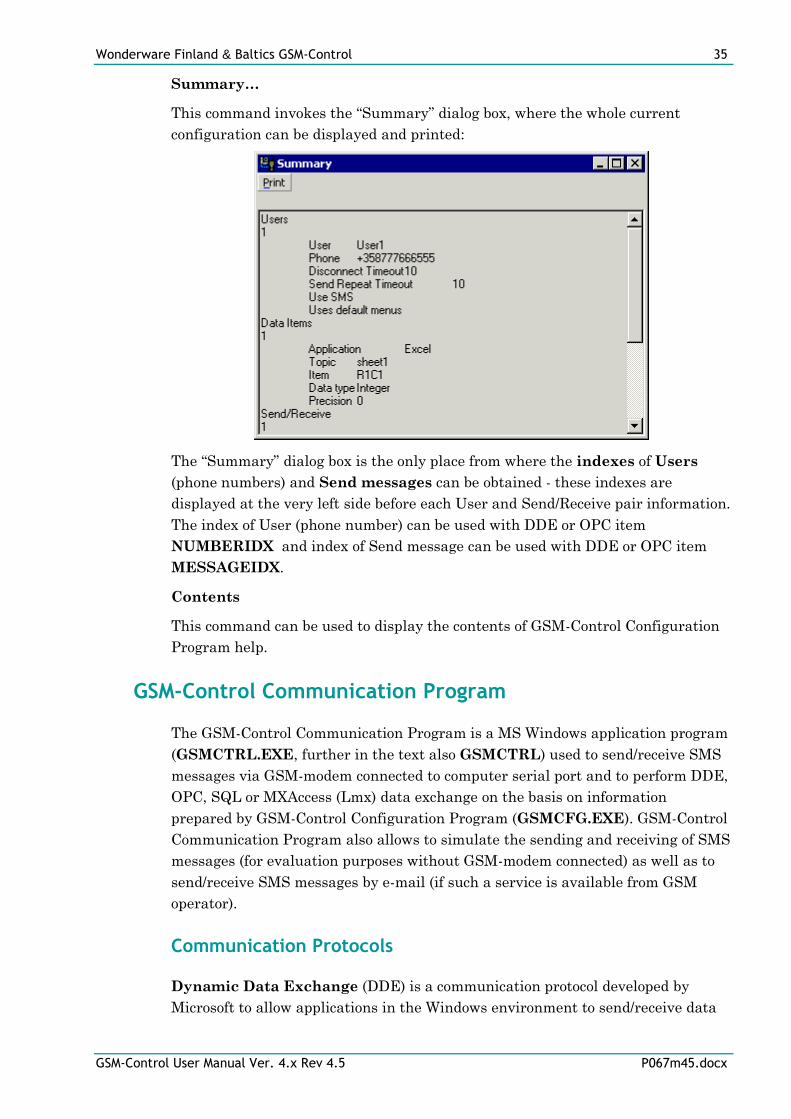
Summary…
This command invokes the “Summary” dialog box, where the whole current
configuration can be displayed and printed:
The “Summary” dialog box is the only place from where the indexes of Users
(phone numbers) and Send messages can be obtained - these indexes are
displayed at the very left side before each User and Send/Receive pair information.
The index of User (phone number) can be used with DDE or OPC item
NUMBERIDX and index of Send message can be used with DDE or OPC item
MESSAGEIDX.
Contents
This command can be used to display the contents of GSM-Control Configuration
Program help.
GSM-Control Communication Program
The GSM-Control Communication Program is a MS Windows application program
(GSMCTRL.EXE, further in the text also GSMCTRL) used to send/receive SMS
messages via GSM-modem connected to computer serial port and to perform DDE,
OPC, SQL or MXAccess (Lmx) data exchange on the basis on information
prepared by GSM-Control Configuration Program (GSMCFG.EXE). GSM-Control
Communication Program also allows to simulate the sending and receiving of SMS
messages (for evaluation purposes without GSM-modem connected) as well as to
send/receive SMS messages by e-mail (if such a service is available from GSM
operator).
Communication Protocols
Dynamic Data Exchange (DDE) is a communication protocol developed by
Microsoft to allow applications in the Windows environment to send/receive data
Wonderware Finland & Baltics GSM-Control 36
GSM-Control User Manual Ver. 4.x Rev 4.5 P067m45.docx
and instructions to/from each other. It implements a client-server relationship
between two concurrently running applications. The server application provides
the data and accepts requests from any other application interested in its data.
Requesting applications are called clients. Some applications such as Wonderware
InTouch and Microsoft Excel can simultaneously be both a client and a server.
OLE for Process Control (OPC) is an open interface standard to provide data
from a data source and communicate the data to any client application in a
common standard way. The OPC is based on Microsoft OLE, COM and DCOM
technologies and enables simple and standardized data interchange between the
industrial or office sector and the production sector. From general point of view
many aspects of OPC are similar to DDE, but main difference is in the
implementation by using Microsoft's COM (Component Object Model) technology.
It enables fast exchange with process automation data and OPC open interface
allows access to data from OPC Server in same standard way from OPC client
applications supplied by different developers.
For more information on the basics of OPC, please refer to the OPC
Specification. The OPC Data Access Custom Interface Specification is
maintained by OPC Foundation, the current specification is 2.04 dated
September 2000.
The GSM-Control OPC support is implemented both as OPC Client and OPC
Server, i.e. GSM-Control Communication Program (GSMCTRL) can request data
as OPC client and also can supply data as OPC server. The GSM-Control OPC
version contains Server (IOPCServer), Group and Item interfaces. The item
browsing and item value time stamping and quality is supported.
The GSM-Control OPC Server part is implemented based on FactorySoft OPC
Server Development Toolkit and it conforms to OPC Data Access Custom
Interface Specification 2.04. The GSM-Control OPC Server part is tested for
compliance and is compatible with OPC Foundation OPC Data Access Compliance
Test Tool. The GSM-Control OPC Client part is implemented by Factory Soft
OPC Client Development Toolkit (version 2.01).
LMX (Lmx Proxy) is a Wonderware library for direct accessing to Wonderware
Application Server Galaxy data via MXAccess interface.
Starting GSMCTRL
If starting GSMCTRL program first time after installation, it automatically will
open and work with default configuration file DEFAULT.XML. To use some other
configuration file, open it from GSMCTRL Main Menu by File/Open command or
start GSMCTRL from command line with this configuration file name specified as
command line parameter, like following:
GSMCTRL c:\gsmctrl\gsmdata.xml
Wonderware Finland & Baltics GSM-Control 37
GSM-Control User Manual Ver. 4.x Rev 4.5 P067m45.docx
The last configuration file used is saved in GSMCTRL.INI file and will be used if
closing GSMCTRL and starting again.
At GSM-Control Communication Program startup, the GSMCTRL main window
appears and the following actions are performed:
- the GSM-Control configuration file is read and checked;
- the DDE, OPC and LMX links specified in the GSM-Control configuration file are
activated; if current GSM-Control configuration contains OPC data items then
GSM-Control tries to start the corresponding OPC Server(s);
- the GSM-modem is initiated depending on current settings;
- if some alarm conditions are configured and some of these alarms are active (the
Alarm item values are non-zero) then corresponding Alarm messages are sent to
Users linked with these Alarm messages.
Note: the configured SQL connections are not initiated at GSMCTRL startup -
these connections are initiated when corresponding SQL statements are executed
first time. Therefore it is very important to check all configured SQL statements by
using GSMCTRL simulation mode.
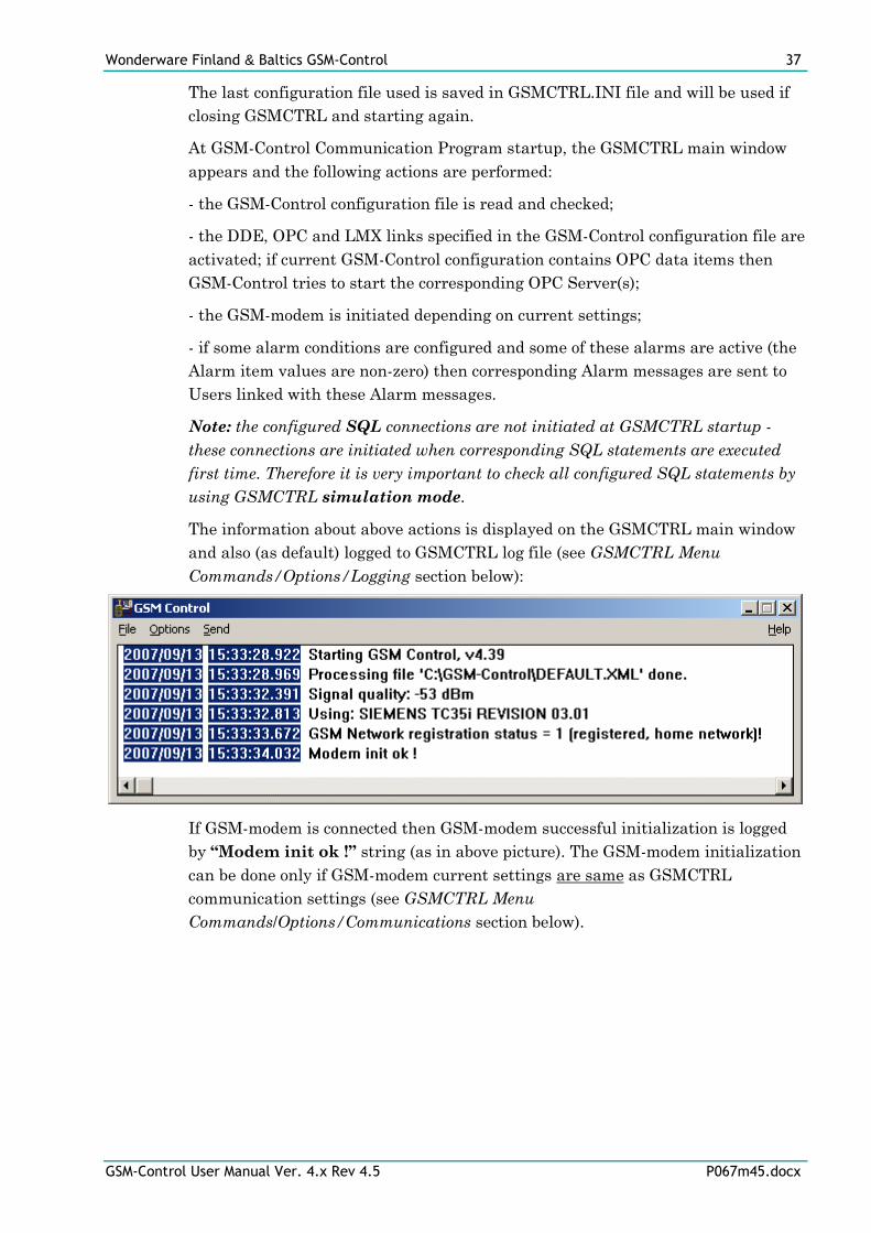
The information about above actions is displayed on the GSMCTRL main window
and also (as default) logged to GSMCTRL log file (see GSMCTRL Menu
Commands/Options/Logging section below):
If GSM-modem is connected then GSM-modem successful initialization is logged
by “Modem init ok !” string (as in above picture). The GSM-modem initialization
can be done only if GSM-modem current settings are same as GSMCTRL
communication settings (see GSMCTRL Menu
Commands/Options/Communications section below).
Wonderware Finland & Baltics GSM-Control 38
GSM-Control User Manual Ver. 4.x Rev 4.5 P067m45.docx
GSMCTRL Menu Commands
The following top-level menu items and corresponding pop-up menus are used.
File
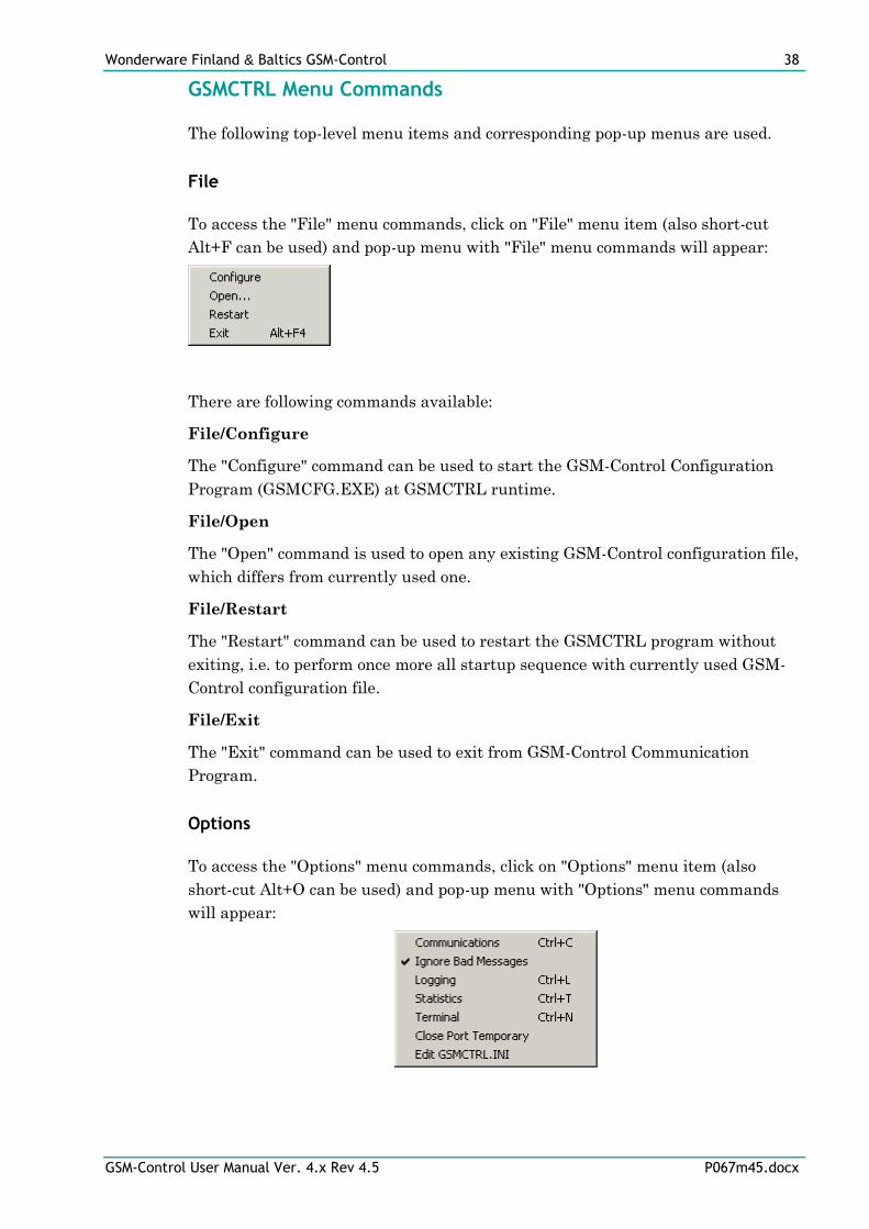
To access the "File" menu commands, click on "File" menu item (also short-cut
Alt+F can be used) and pop-up menu with "File" menu commands will appear:
There are following commands available:
File/Configure
The "Configure" command can be used to start the GSM-Control Configuration
Program (GSMCFG.EXE) at GSMCTRL runtime.
File/Open
The "Open" command is used to open any existing GSM-Control configuration file,
which differs from currently used one.
File/Restart
The "Restart" command can be used to restart the GSMCTRL program without
exiting, i.e. to perform once more all startup sequence with currently used GSM-
Control configuration file.
File/Exit
The "Exit" command can be used to exit from GSM-Control Communication
Program.
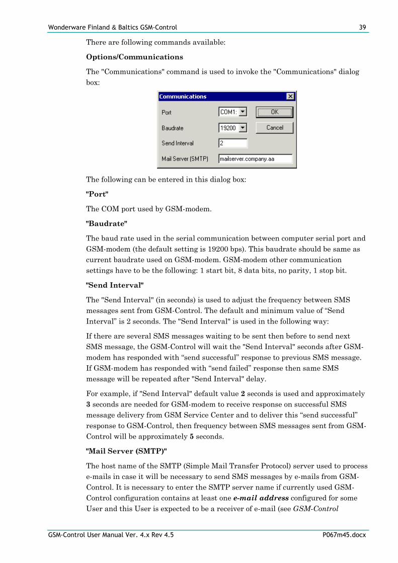
Options
To access the "Options" menu commands, click on "Options" menu item (also
short-cut Alt+O can be used) and pop-up menu with "Options" menu commands
will appear:
Wonderware Finland & Baltics GSM-Control 39
GSM-Control User Manual Ver. 4.x Rev 4.5 P067m45.docx
There are following commands available:
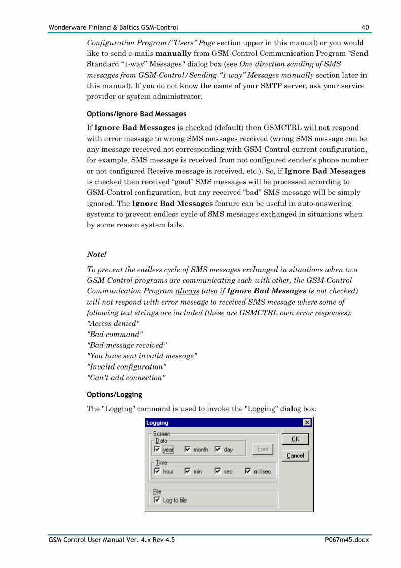
Options/Communications
The "Communications" command is used to invoke the "Communications" dialog
box:
The following can be entered in this dialog box:
"Port"
The COM port used by GSM-modem.
"Baudrate"
The baud rate used in the serial communication between computer serial port and
GSM-modem (the default setting is 19200 bps). This baudrate should be same as
current baudrate used on GSM-modem. GSM-modem other communication
settings have to be the following: 1 start bit, 8 data bits, no parity, 1 stop bit.
"Send Interval"
The "Send Interval" (in seconds) is used to adjust the frequency between SMS
messages sent from GSM-Control. The default and minimum value of “Send
Interval” is 2 seconds. The "Send Interval" is used in the following way:
If there are several SMS messages waiting to be sent then before to send next
SMS message, the GSM-Control will wait the "Send Interval" seconds after GSM-
modem has responded with “send successful” response to previous SMS message.
If GSM-modem has responded with “send failed” response then same SMS
message will be repeated after "Send Interval" delay.
For example, if "Send Interval" default value 2 seconds is used and approximately
3 seconds are needed for GSM-modem to receive response on successful SMS
message delivery from GSM Service Center and to deliver this “send successful”
response to GSM-Control, then frequency between SMS messages sent from GSM-
Control will be approximately 5 seconds.
"Mail Server (SMTP)"
The host name of the SMTP (Simple Mail Transfer Protocol) server used to process
e-mails in case it will be necessary to send SMS messages by e-mails from GSM-
Control. It is necessary to enter the SMTP server name if currently used GSM-
Control configuration contains at least one e-mail address configured for some
User and this User is expected to be a receiver of e-mail (see GSM-Control
Wonderware Finland & Baltics GSM-Control 40
GSM-Control User Manual Ver. 4.x Rev 4.5 P067m45.docx
Configuration Program/”Users” Page section upper in this manual) or you would
like to send e-mails manually from GSM-Control Communication Program "Send
Standard “1-way” Messages" dialog box (see One direction sending of SMS
messages from GSM-Control/Sending “1-way” Messages manually section later in
this manual). If you do not know the name of your SMTP server, ask your service
provider or system administrator.
Options/Ignore Bad Messages
If Ignore Bad Messages is checked (default) then GSMCTRL will not respond
with error message to wrong SMS messages received (wrong SMS message can be
any message received not corresponding with GSM-Control current configuration,
for example, SMS message is received from not configured sender’s phone number
or not configured Receive message is received, etc.). So, if Ignore Bad Messages
is checked then received “good” SMS messages will be processed according to
GSM-Control configuration, but any received “bad” SMS message will be simply
ignored. The Ignore Bad Messages feature can be useful in auto-answering
systems to prevent endless cycle of SMS messages exchanged in situations when
by some reason system fails.
Note!
To prevent the endless cycle of SMS messages exchanged in situations when two
GSM-Control programs are communicating each with other, the GSM-Control
Communication Program always (also if Ignore Bad Messages is not checked)
will not respond with error message to received SMS message where some of
following text strings are included (these are GSMCTRL own error responses):
"Access denied"
"Bad command"
"Bad message received"
"You have sent invalid message"
"Invalid configuration"
"Can't add connection"
Options/Logging
The "Logging" command is used to invoke the "Logging" dialog box:
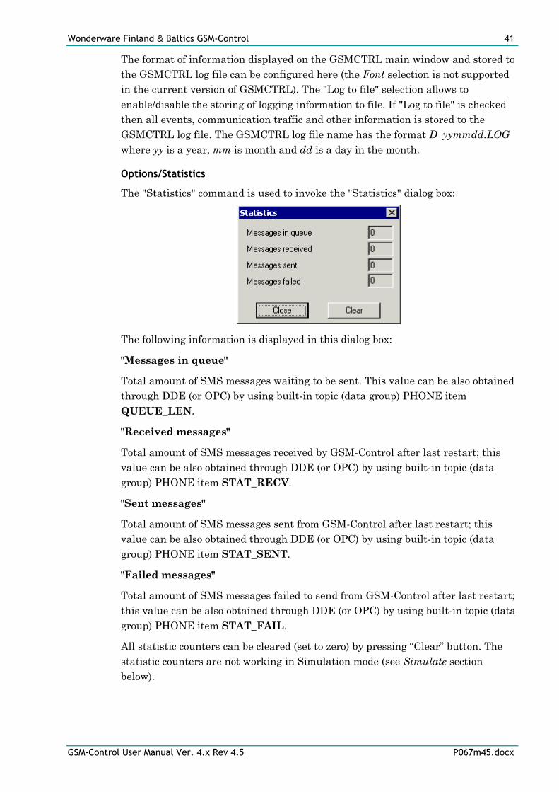
Wonderware Finland & Baltics GSM-Control 41
GSM-Control User Manual Ver. 4.x Rev 4.5 P067m45.docx
The format of information displayed on the GSMCTRL main window and stored to
the GSMCTRL log file can be configured here (the Font selection is not supported
in the current version of GSMCTRL). The "Log to file" selection allows to
enable/disable the storing of logging information to file. If "Log to file" is checked
then all events, communication traffic and other information is stored to the
GSMCTRL log file. The GSMCTRL log file name has the format D_yymmdd.LOG
where yy is a year, mm is month and dd is a day in the month.
Options/Statistics
The "Statistics" command is used to invoke the "Statistics" dialog box:
The following information is displayed in this dialog box:
"Messages in queue"
Total amount of SMS messages waiting to be sent. This value can be also obtained
through DDE (or OPC) by using built-in topic (data group) PHONE item
QUEUE_LEN.
"Received messages"
Total amount of SMS messages received by GSM-Control after last restart; this
value can be also obtained through DDE (or OPC) by using built-in topic (data
group) PHONE item STAT_RECV.
"Sent messages"
Total amount of SMS messages sent from GSM-Control after last restart; this
value can be also obtained through DDE (or OPC) by using built-in topic (data
group) PHONE item STAT_SENT.
"Failed messages"
Total amount of SMS messages failed to send from GSM-Control after last restart;
this value can be also obtained through DDE (or OPC) by using built-in topic (data
group) PHONE item STAT_FAIL.
All statistic counters can be cleared (set to zero) by pressing “Clear” button. The
statistic counters are not working in Simulation mode (see Simulate section
below).
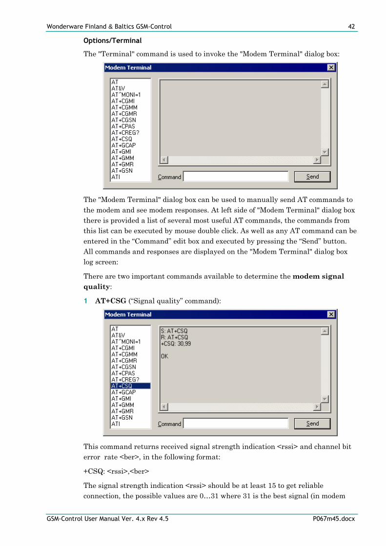
Wonderware Finland & Baltics GSM-Control 42
GSM-Control User Manual Ver. 4.x Rev 4.5 P067m45.docx
Options/Terminal
The "Terminal" command is used to invoke the "Modem Terminal" dialog box:
The "Modem Terminal" dialog box can be used to manually send AT commands to
the modem and see modem responses. At left side of "Modem Terminal" dialog box
there is provided a list of several most useful AT commands, the commands from
this list can be executed by mouse double click. As well as any AT command can be
entered in the “Command” edit box and executed by pressing the “Send” button.
All commands and responses are displayed on the "Modem Terminal" dialog box
log screen:
There are two important commands available to determine the modem signal
quality:
1 AT+CSG (“Signal quality” command):
This command returns received signal strength indication <rssi> and channel bit
error rate <ber>, in the following format:
+CSQ: <rssi>,<ber>
The signal strength indication <rssi> should be at least 15 to get reliable
connection, the possible values are 0…31 where 31 is the best signal (in modem
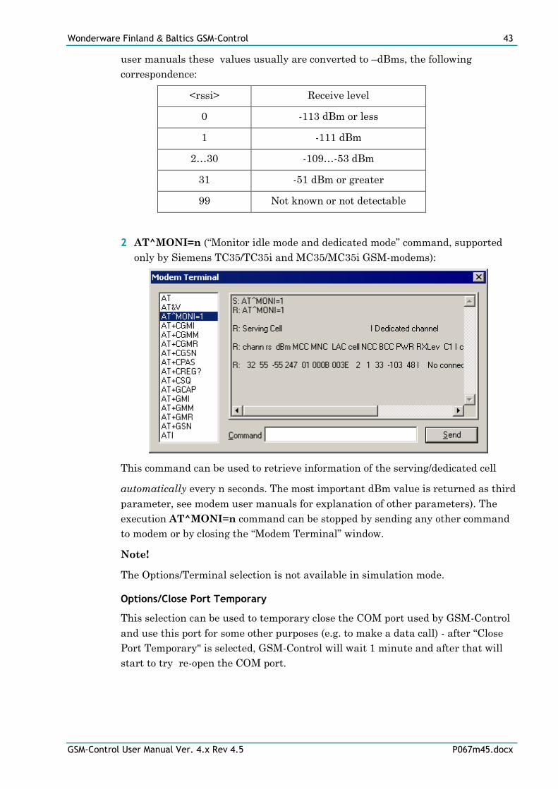
Wonderware Finland & Baltics GSM-Control 43
GSM-Control User Manual Ver. 4.x Rev 4.5 P067m45.docx
user manuals these values usually are converted to –dBms, the following
correspondence:
<rssi> Receive level
0 -113 dBm or less
1 -111 dBm
2…30 -109…-53 dBm
31 -51 dBm or greater
99 Not known or not detectable
2 AT^MONI=n (“Monitor idle mode and dedicated mode” command, supported
only by Siemens TC35/TC35i and MC35/MC35i GSM-modems):
This command can be used to retrieve information of the serving/dedicated cell
automatically every n seconds. The most important dBm value is returned as third
parameter, see modem user manuals for explanation of other parameters). The
execution AT^MONI=n command can be stopped by sending any other command
to modem or by closing the “Modem Terminal” window.
Note!
The Options/Terminal selection is not available in simulation mode.
Options/Close Port Temporary
This selection can be used to temporary close the COM port used by GSM-Control
and use this port for some other purposes (e.g. to make a data call) - after “Close
Port Temporary" is selected, GSM-Control will wait 1 minute and after that will
start to try re-open the COM port.
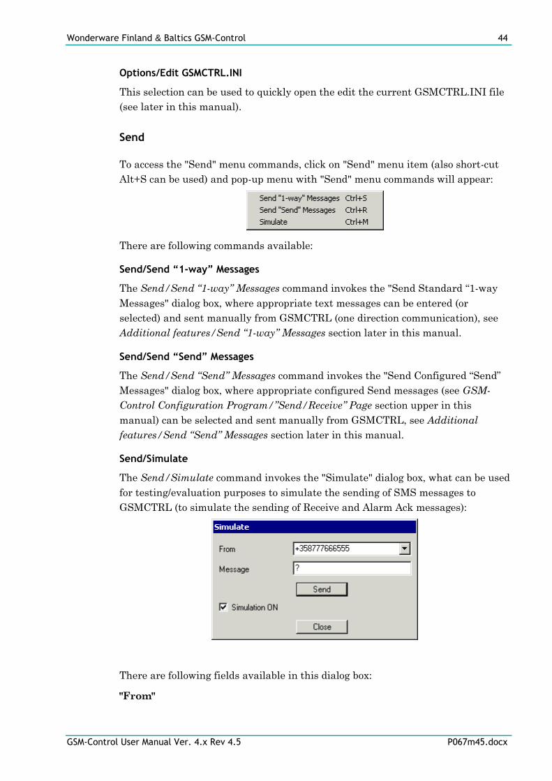
Wonderware Finland & Baltics GSM-Control 44
GSM-Control User Manual Ver. 4.x Rev 4.5 P067m45.docx
Options/Edit GSMCTRL.INI
This selection can be used to quickly open the edit the current GSMCTRL.INI file
(see later in this manual).
Send
To access the "Send" menu commands, click on "Send" menu item (also short-cut
Alt+S can be used) and pop-up menu with "Send" menu commands will appear:
There are following commands available:
Send/Send “1-way” Messages
The Send/Send “1-way” Messages command invokes the "Send Standard “1-way
Messages" dialog box, where appropriate text messages can be entered (or
selected) and sent manually from GSMCTRL (one direction communication), see
Additional features/Send “1-way” Messages section later in this manual.
Send/Send “Send” Messages
The Send/Send “Send” Messages command invokes the "Send Configured “Send”
Messages" dialog box, where appropriate configured Send messages (see GSM-
Control Configuration Program/”Send/Receive” Page section upper in this
manual) can be selected and sent manually from GSMCTRL, see Additional
features/Send “Send” Messages section later in this manual.
Send/Simulate
The Send/Simulate command invokes the "Simulate" dialog box, what can be used
for testing/evaluation purposes to simulate the sending of SMS messages to
GSMCTRL (to simulate the sending of Receive and Alarm Ack messages):
There are following fields available in this dialog box:
"From"
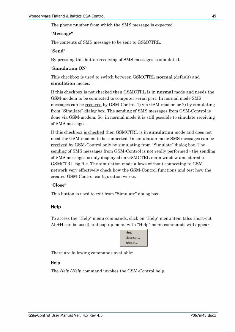
Wonderware Finland & Baltics GSM-Control 45
GSM-Control User Manual Ver. 4.x Rev 4.5 P067m45.docx
The phone number from which the SMS message is expected.
"Message"
The contents of SMS message to be sent to GSMCTRL.
"Send"
By pressing this button receiving of SMS messages is simulated.
"Simulation ON"
This checkbox is used to switch between GSMCTRL normal (default) and
simulation modes.
If this checkbox is not checked then GSMCTRL is in normal mode and needs the
GSM-modem to be connected to computer serial port. In normal mode SMS
messages can be received by GSM-Control 1) via GSM-modem or 2) by simulating
from “Simulate” dialog box. The sending of SMS messages from GSM-Control is
done via GSM-modem. So, in normal mode it is still possible to simulate receiving
of SMS messages.
If this checkbox is checked then GSMCTRL is in simulation mode and does not
need the GSM-modem to be connected. In simulation mode SMS messages can be
received by GSM-Control only by simulating from “Simulate” dialog box. The
sending of SMS messages from GSM-Control is not really performed - the sending
of SMS messages is only displayed on GSMCTRL main window and stored to
GSMCTRL log file. The simulation mode allows without connecting to GSM
network very effectively check how the GSM-Control functions and test how the
created GSM-Control configuration works.
"Close"
This button is used to exit from "Simulate" dialog box.
Help
To access the "Help" menu commands, click on "Help" menu item (also short-cut
Alt+H can be used) and pop-up menu with "Help" menu commands will appear:
There are following commands available:
Help
The Help/Help command invokes the GSM-Control help.
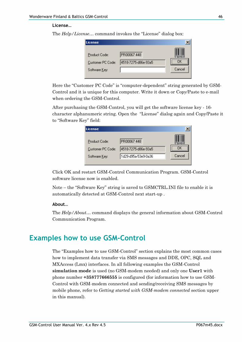
Wonderware Finland & Baltics GSM-Control 46
GSM-Control User Manual Ver. 4.x Rev 4.5 P067m45.docx
License…
The Help/License… command invokes the “License” dialog box:
Here the “Customer PC Code” is “computer-dependent” string generated by GSM-
Control and it is unique for this computer. Write it down or Copy/Paste to e-mail
when ordering the GSM-Control.
After purchasing the GSM-Control, you will get the software license key - 16-
character alphanumeric string. Open the “License” dialog again and Copy/Paste it
to “Software Key” field:
Click OK and restart GSM-Control Communication Program. GSM-Control
software license now is enabled.
Note – the “Software Key” string is saved to GSMCTRL.INI file to enable it is
automatically detected at GSM-Control next start-up .
About…
The Help/About… command displays the general information about GSM-Control
Communication Program.
Examples how to use GSM-Control
The “Examples how to use GSM-Control” section explains the most common cases
how to implement data transfer via SMS messages and DDE, OPC, SQL and
MXAccess (Lmx) interfaces. In all following examples the GSM-Control
simulation mode is used (no GSM-modem needed) and only one User1 with
phone number +358777666555 is configured (for information how to use GSM-
Control with GSM-modem connected and sending/receiving SMS messages by
mobile phone, refer to Getting started with GSM-modem connected section upper
in this manual).
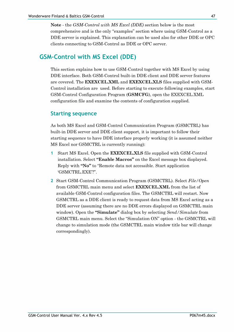
Wonderware Finland & Baltics GSM-Control 47
GSM-Control User Manual Ver. 4.x Rev 4.5 P067m45.docx
Note - the GSM-Control with MS Excel (DDE) section below is the most
comprehensive and is the only “examples” section where using GSM-Control as a
DDE server is explained. This explanation can be used also for other DDE or OPC
clients connecting to GSM-Control as DDE or OPC server.
GSM-Control with MS Excel (DDE)
This section explains how to use GSM-Control together with MS Excel by using
DDE interface. Both GSM-Control built-in DDE client and DDE server features
are covered. The EXEXCEL.XML and EXEXCEL.XLS files supplied with GSM-
Control installation are used. Before starting to execute following examples, start
GSM-Control Configuration Program (GSMCFG), open the EXEXCEL.XML
configuration file and examine the contents of configuration supplied.
Starting sequence
As both MS Excel and GSM-Control Communication Program (GSMCTRL) has
built-in DDE server and DDE client support, it is important to follow their
starting sequence to have DDE interface properly working (it is assumed neither
MS Excel nor GSMCTRL is currently running):
1 Start MS Excel. Open the EXEXCEL.XLS file supplied with GSM-Control
installation. Select “Enable Macros” on the Excel message box displayed.
Reply with “No” to “Remote data not accessible. Start application
‘GSMCTRL.EXE’?”.
2 Start GSM-Control Communication Program (GSMCTRL). Select File/Open
from GSMCTRL main menu and select EXEXCEL.XML from the list of
available GSM-Control configuration files. The GSMCTRL will restart. Now
GSMCTRL as a DDE client is ready to request data from MS Excel acting as a
DDE server (assuming there are no DDE errors displayed on GSMCTRL main
window). Open the “Simulate” dialog box by selecting Send/Simulate from
GSMCTRL main menu. Select the “Simulation ON” option - the GSMCTRL will
change to simulation mode (the GSMCTRL main window title bar will change
correspondingly).
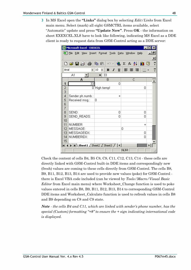
Wonderware Finland & Baltics GSM-Control 48
GSM-Control User Manual Ver. 4.x Rev 4.5 P067m45.docx
3 In MS Excel open the “Links” dialog box by selecting Edit/Links from Excel
main menu. Select (mark) all eight GSMCTRL items available, select
“Automatic” update and press “Update Now”. Press OK - the information on
sheet EXEXCEL.XLS have to look like following, indicating MS Excel as a DDE
client is ready to request data from GSM-Control acting as a DDE server:
Check the content of cells B4, B5 C8, C9, C11, C12, C13, C14 - these cells are
directly linked with GSM-Control built-in DDE items and correspondingly new
(fresh) values are coming to these cells directly from GSM-Control. The cells B8,
B9, B11, B12, B13, B14 are used to provide new values (poke) for GSM-Control -
there is Excel VBA code included (can be viewed by Tools/Macro/Visual Basic
Editor from Excel main menu) where Worksheet_Change function is used to poke
values entered in cells B8, B9, B11, B12, B13, B14 to corresponding GSM-Control
DDE items and Worksheet_Calculate function is used to refresh values in cells B8
and B9 depending on C8 and C9 state.
Note - the cells B4 and C11, which are linked with sender’s phone number, has the
special (Custom) formatting “+#” to ensure the + sign indicating international code
is displayed.
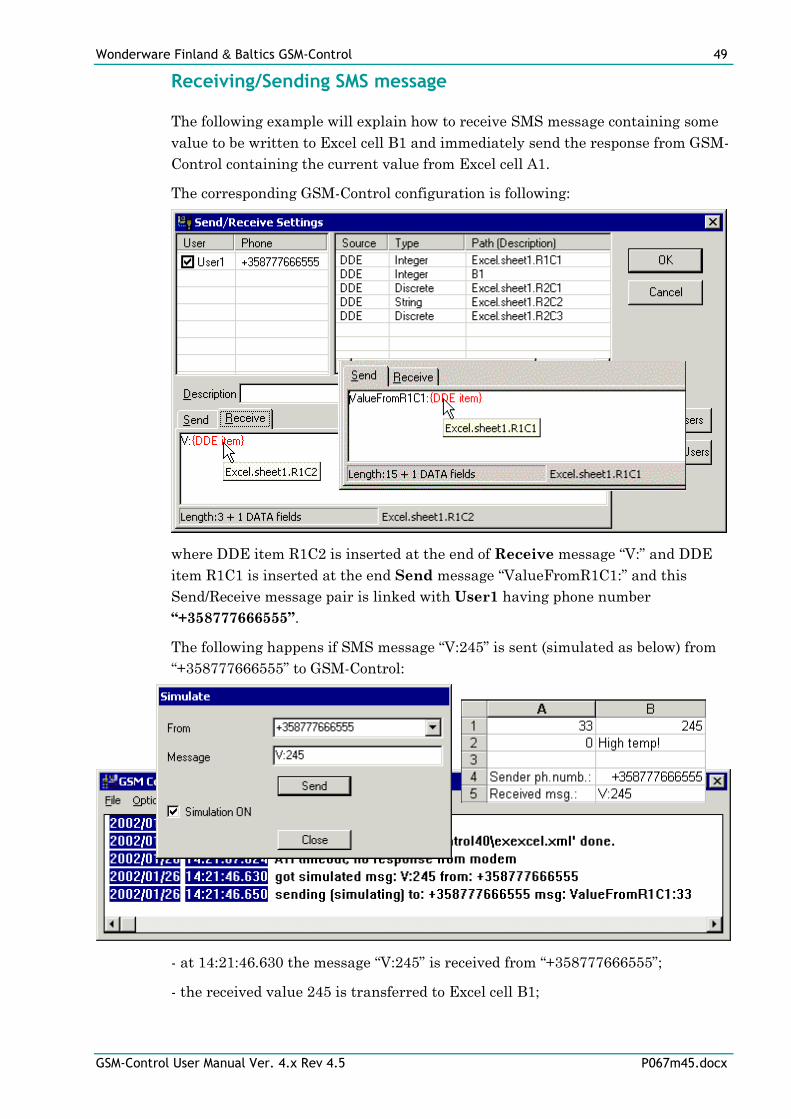
Wonderware Finland & Baltics GSM-Control 49
GSM-Control User Manual Ver. 4.x Rev 4.5 P067m45.docx
Receiving/Sending SMS message
The following example will explain how to receive SMS message containing some
value to be written to Excel cell B1 and immediately send the response from GSM-
Control containing the current value from Excel cell A1.
The corresponding GSM-Control configuration is following:
where DDE item R1C2 is inserted at the end of Receive message “V:” and DDE
item R1C1 is inserted at the end Send message “ValueFromR1C1:” and this
Send/Receive message pair is linked with User1 having phone number
“+358777666555”.
The following happens if SMS message “V:245” is sent (simulated as below) from
“+358777666555” to GSM-Control:
- at 14:21:46.630 the message “V:245” is received from “+358777666555”;
- the received value 245 is transferred to Excel cell B1;
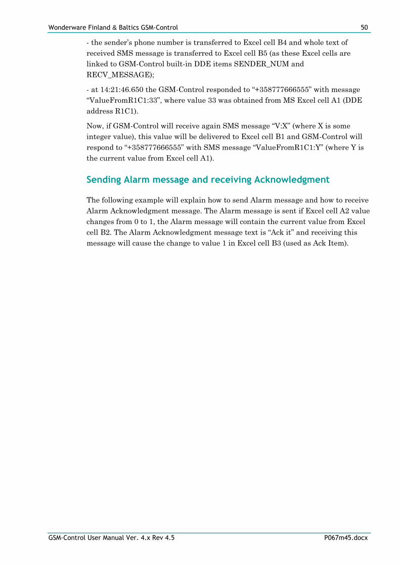
Wonderware Finland & Baltics GSM-Control 50
GSM-Control User Manual Ver. 4.x Rev 4.5 P067m45.docx
- the sender’s phone number is transferred to Excel cell B4 and whole text of
received SMS message is transferred to Excel cell B5 (as these Excel cells are
linked to GSM-Control built-in DDE items SENDER_NUM and
RECV_MESSAGE);
- at 14:21:46.650 the GSM-Control responded to “+358777666555” with message
“ValueFromR1C1:33”, where value 33 was obtained from MS Excel cell A1 (DDE
address R1C1).
Now, if GSM-Control will receive again SMS message “V:X” (where X is some
integer value), this value will be delivered to Excel cell B1 and GSM-Control will
respond to “+358777666555” with SMS message “ValueFromR1C1:Y” (where Y is
the current value from Excel cell A1).
Sending Alarm message and receiving Acknowledgment
The following example will explain how to send Alarm message and how to receive
Alarm Acknowledgment message. The Alarm message is sent if Excel cell A2 value
changes from 0 to 1, the Alarm message will contain the current value from Excel
cell B2. The Alarm Acknowledgment message text is “Ack it” and receiving this
message will cause the change to value 1 in Excel cell B3 (used as Ack Item).
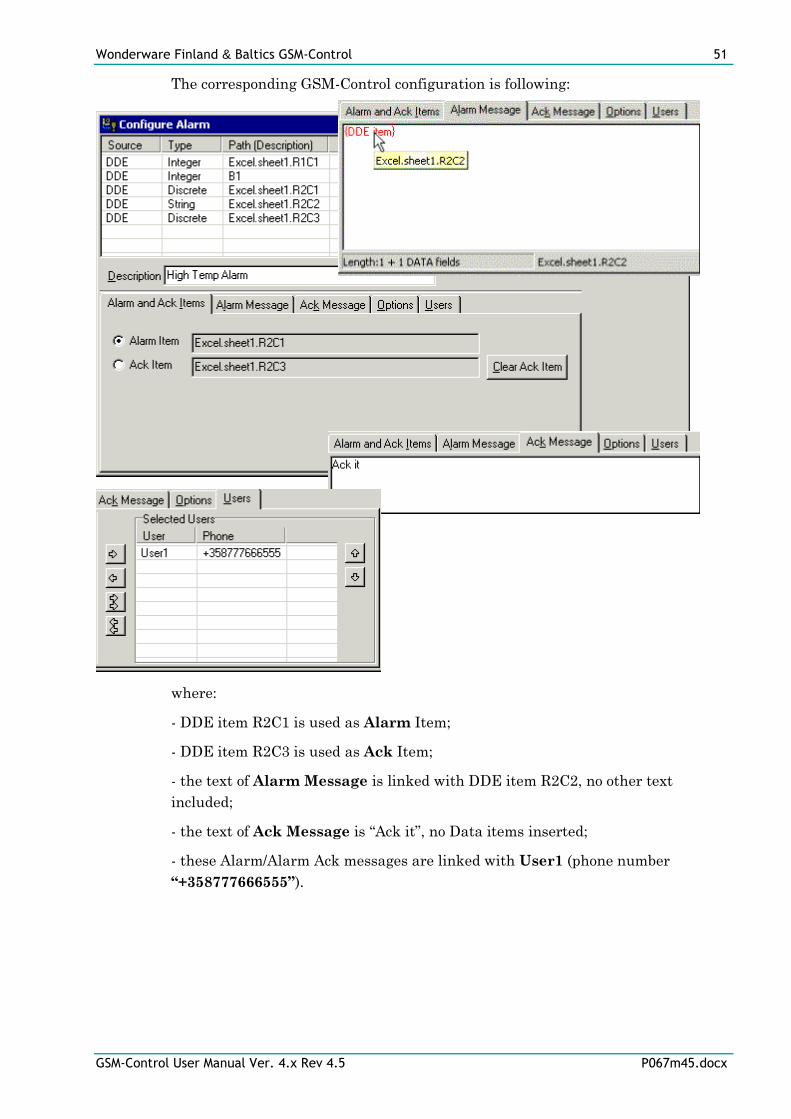
Wonderware Finland & Baltics GSM-Control 51
GSM-Control User Manual Ver. 4.x Rev 4.5 P067m45.docx
The corresponding GSM-Control configuration is following:
where:
- DDE item R2C1 is used as Alarm Item;
- DDE item R2C3 is used as Ack Item;
- the text of Alarm Message is linked with DDE item R2C2, no other text
included;
- the text of Ack Message is “Ack it”, no Data items inserted;
- these Alarm/Alarm Ack messages are linked with User1 (phone number
“+358777666555”).
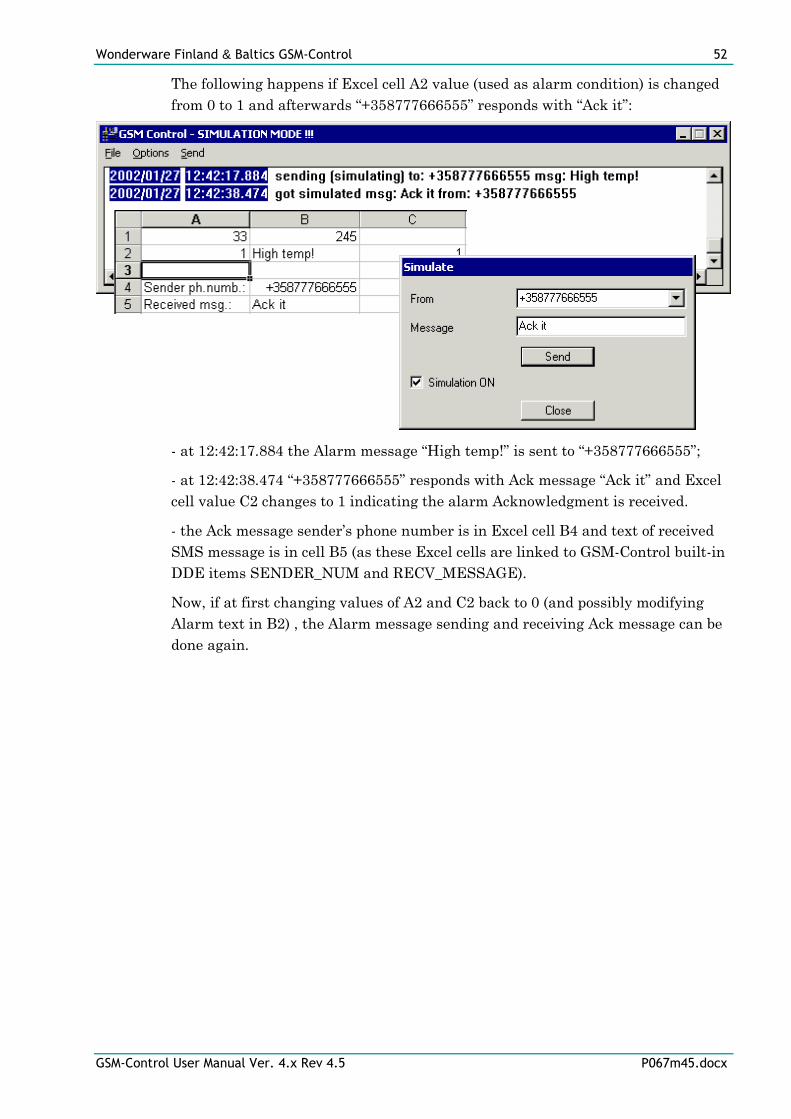
Wonderware Finland & Baltics GSM-Control 52
GSM-Control User Manual Ver. 4.x Rev 4.5 P067m45.docx
The following happens if Excel cell A2 value (used as alarm condition) is changed
from 0 to 1 and afterwards “+358777666555” responds with “Ack it”:
- at 12:42:17.884 the Alarm message “High temp!” is sent to “+358777666555”;
- at 12:42:38.474 “+358777666555” responds with Ack message “Ack it” and Excel
cell value C2 changes to 1 indicating the alarm Acknowledgment is received.
- the Ack message sender’s phone number is in Excel cell B4 and text of received
SMS message is in cell B5 (as these Excel cells are linked to GSM-Control built-in
DDE items SENDER_NUM and RECV_MESSAGE).
Now, if at first changing values of A2 and C2 back to 0 (and possibly modifying
Alarm text in B2) , the Alarm message sending and receiving Ack message can be
done again.
Wonderware Finland & Baltics GSM-Control 53
GSM-Control User Manual Ver. 4.x Rev 4.5 P067m45.docx
Sending any SMS message to any phone number
This is an easiest way to send any SMS message from DDE client (MS Excel in
our case) via GSM-Control (as DDE server) to any phone number. In following
example: 1) at first the receiver’s phone number (“+358400400400” in example
below) is entered into cell B11 (linked with GSM-Control built-in DDE item
NUMBER) and text of message (“Test message1” in example below) is entered
into cell B12 (linked with GSM-Control built-in DDE item MESSAGE) and 2) then
value 1 is entered into cell B8 (linked with GSM-Control built-in DDE item
SEND). After sending of SMS message the value of SEND changes back to 0:
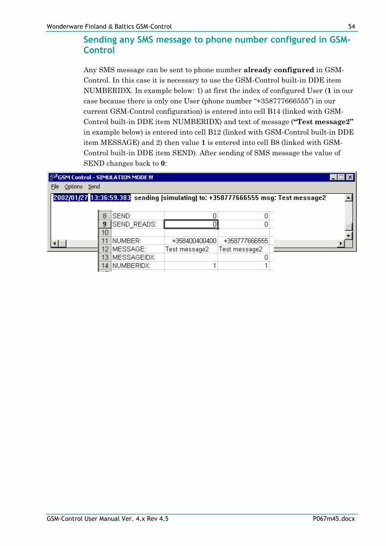
Wonderware Finland & Baltics GSM-Control 54
GSM-Control User Manual Ver. 4.x Rev 4.5 P067m45.docx
Sending any SMS message to phone number configured in GSM-Control
Any SMS message can be sent to phone number already configured in GSM-
Control. In this case it is necessary to use the GSM-Control built-in DDE item
NUMBERIDX. In example below: 1) at first the index of configured User (1 in our
case because there is only one User (phone number “+358777666555”) in our
current GSM-Control configuration) is entered into cell B14 (linked with GSM-
Control built-in DDE item NUMBERIDX) and text of message (“Test message2”
in example below) is entered into cell B12 (linked with GSM-Control built-in DDE
item MESSAGE) and 2) then value 1 is entered into cell B8 (linked with GSM-
Control built-in DDE item SEND). After sending of SMS message the value of
SEND changes back to 0:
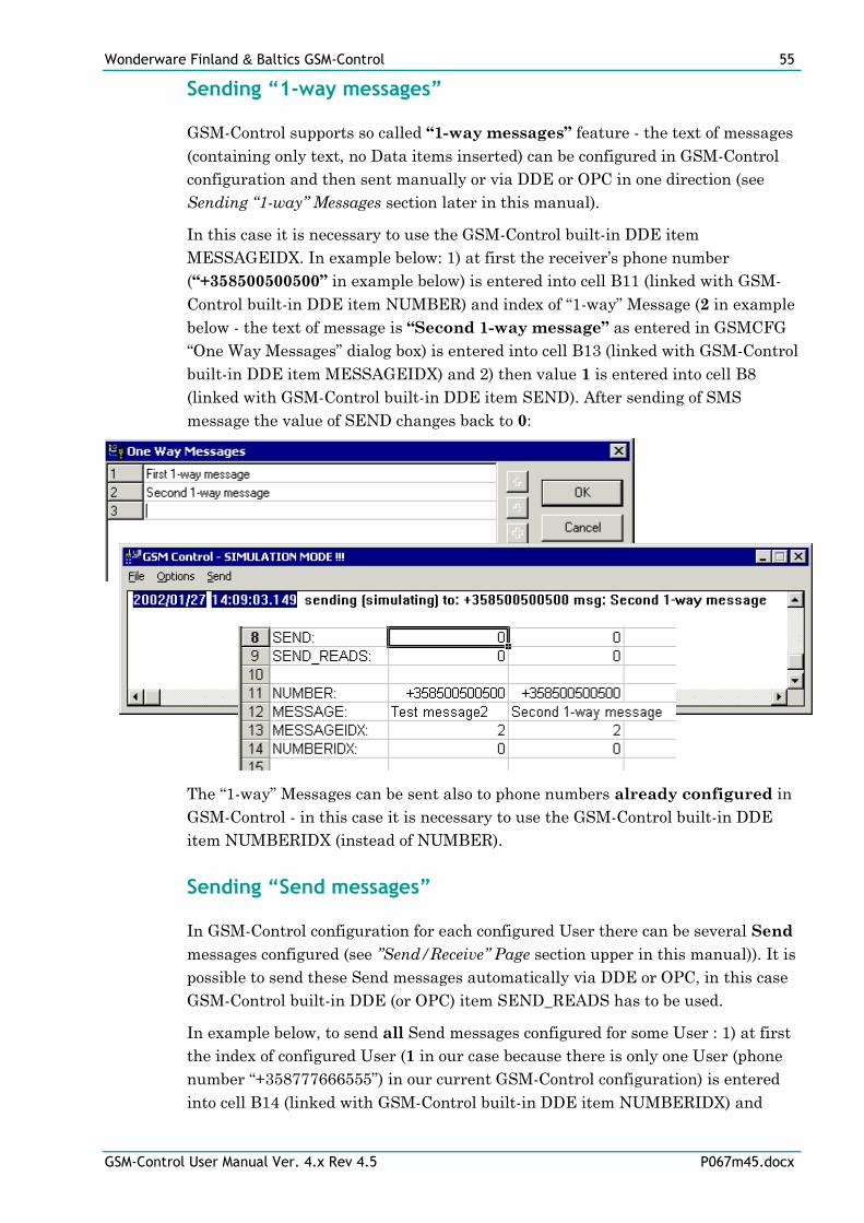
Wonderware Finland & Baltics GSM-Control 55
GSM-Control User Manual Ver. 4.x Rev 4.5 P067m45.docx
Sending “1-way messages”
GSM-Control supports so called “1-way messages” feature - the text of messages
(containing only text, no Data items inserted) can be configured in GSM-Control
configuration and then sent manually or via DDE or OPC in one direction (see
Sending “1-way” Messages section later in this manual).
In this case it is necessary to use the GSM-Control built-in DDE item
MESSAGEIDX. In example below: 1) at first the receiver’s phone number
(“+358500500500” in example below) is entered into cell B11 (linked with GSM-
Control built-in DDE item NUMBER) and index of “1-way” Message (2 in example
below - the text of message is “Second 1-way message” as entered in GSMCFG
“One Way Messages” dialog box) is entered into cell B13 (linked with GSM-Control
built-in DDE item MESSAGEIDX) and 2) then value 1 is entered into cell B8
(linked with GSM-Control built-in DDE item SEND). After sending of SMS
message the value of SEND changes back to 0:
The “1-way” Messages can be sent also to phone numbers already configured in
GSM-Control - in this case it is necessary to use the GSM-Control built-in DDE
item NUMBERIDX (instead of NUMBER).
Sending “Send messages”
In GSM-Control configuration for each configured User there can be several Send
messages configured (see ”Send/Receive” Page section upper in this manual)). It is
possible to send these Send messages automatically via DDE or OPC, in this case
GSM-Control built-in DDE (or OPC) item SEND_READS has to be used.
In example below, to send all Send messages configured for some User : 1) at first
the index of configured User (1 in our case because there is only one User (phone
number “+358777666555”) in our current GSM-Control configuration) is entered
into cell B14 (linked with GSM-Control built-in DDE item NUMBERIDX) and
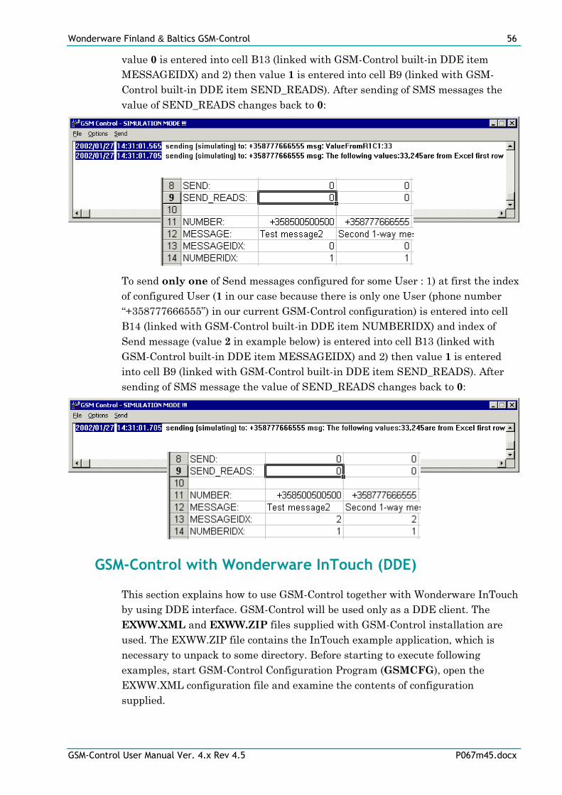
Wonderware Finland & Baltics GSM-Control 56
GSM-Control User Manual Ver. 4.x Rev 4.5 P067m45.docx
value 0 is entered into cell B13 (linked with GSM-Control built-in DDE item
MESSAGEIDX) and 2) then value 1 is entered into cell B9 (linked with GSM-
Control built-in DDE item SEND_READS). After sending of SMS messages the
value of SEND_READS changes back to 0:
To send only one of Send messages configured for some User : 1) at first the index
of configured User (1 in our case because there is only one User (phone number
“+358777666555”) in our current GSM-Control configuration) is entered into cell
B14 (linked with GSM-Control built-in DDE item NUMBERIDX) and index of
Send message (value 2 in example below) is entered into cell B13 (linked with
GSM-Control built-in DDE item MESSAGEIDX) and 2) then value 1 is entered
into cell B9 (linked with GSM-Control built-in DDE item SEND_READS). After
sending of SMS message the value of SEND_READS changes back to 0:
GSM-Control with Wonderware InTouch (DDE)
This section explains how to use GSM-Control together with Wonderware InTouch
by using DDE interface. GSM-Control will be used only as a DDE client. The
EXWW.XML and EXWW.ZIP files supplied with GSM-Control installation are
used. The EXWW.ZIP file contains the InTouch example application, which is
necessary to unpack to some directory. Before starting to execute following
examples, start GSM-Control Configuration Program (GSMCFG), open the
EXWW.XML configuration file and examine the contents of configuration
supplied.
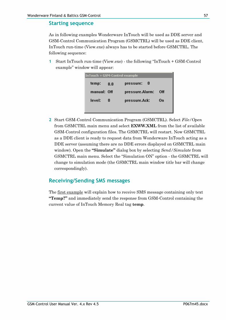
Wonderware Finland & Baltics GSM-Control 57
GSM-Control User Manual Ver. 4.x Rev 4.5 P067m45.docx
Starting sequence
As in following examples Wonderware InTouch will be used as DDE server and
GSM-Control Communication Program (GSMCTRL) will be used as DDE client,
InTouch run-time (View.exe) always has to be started before GSMCTRL. The
following sequence:
1 Start InTouch run-time (View.exe) - the following “InTouch + GSM-Control
example” window will appear:
2 Start GSM-Control Communication Program (GSMCTRL). Select File/Open
from GSMCTRL main menu and select EXWW.XML from the list of available
GSM-Control configuration files. The GSMCTRL will restart. Now GSMCTRL
as a DDE client is ready to request data from Wonderware InTouch acting as a
DDE server (assuming there are no DDE errors displayed on GSMCTRL main
window). Open the “Simulate” dialog box by selecting Send/Simulate from
GSMCTRL main menu. Select the “Simulation ON” option - the GSMCTRL will
change to simulation mode (the GSMCTRL main window title bar will change
correspondingly).
Receiving/Sending SMS messages
The first example will explain how to receive SMS message containing only text
“Temp?” and immediately send the response from GSM-Control containing the
current value of InTouch Memory Real tag temp.
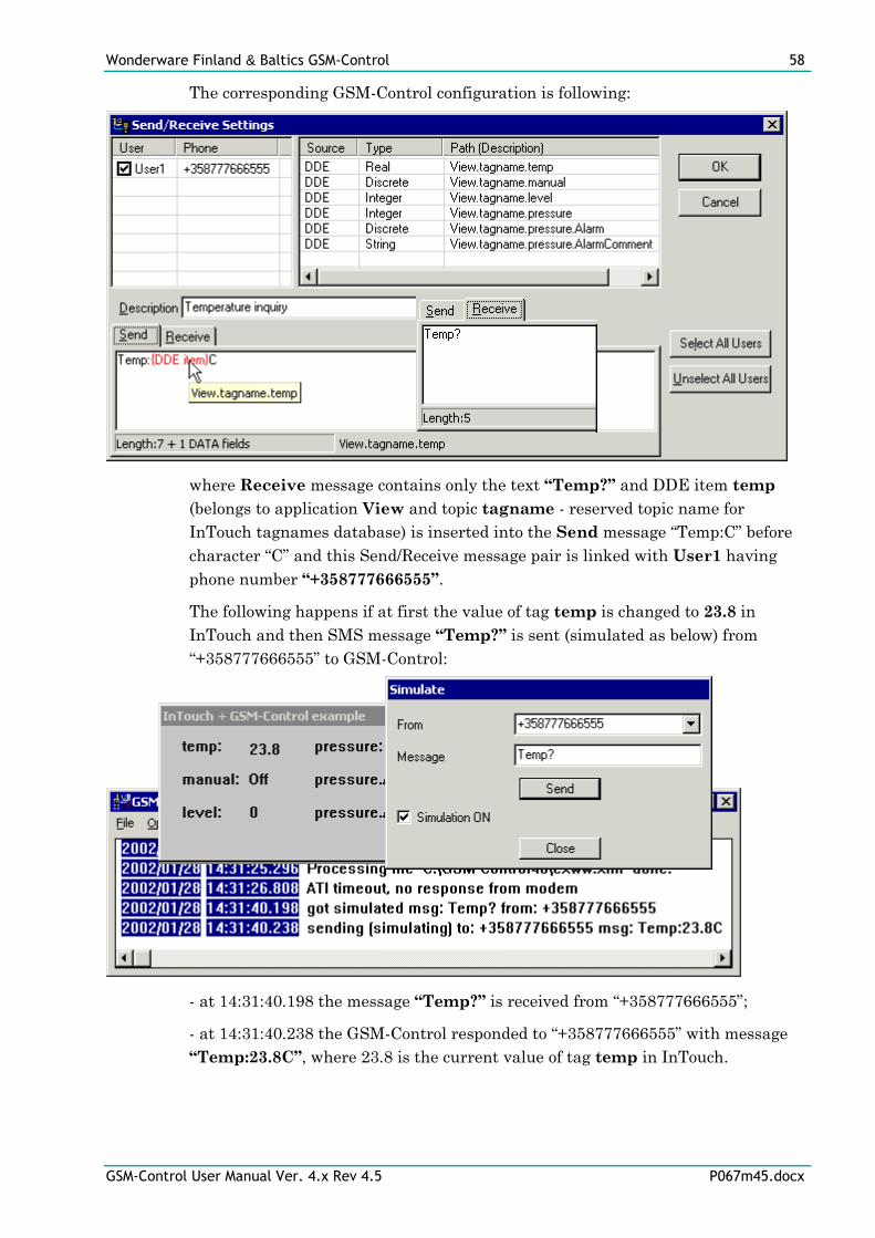
Wonderware Finland & Baltics GSM-Control 58
GSM-Control User Manual Ver. 4.x Rev 4.5 P067m45.docx
The corresponding GSM-Control configuration is following:
where Receive message contains only the text “Temp?” and DDE item temp
(belongs to application View and topic tagname - reserved topic name for
InTouch tagnames database) is inserted into the Send message “Temp:C” before
character “C” and this Send/Receive message pair is linked with User1 having
phone number “+358777666555”.
The following happens if at first the value of tag temp is changed to 23.8 in
InTouch and then SMS message “Temp?” is sent (simulated as below) from
“+358777666555” to GSM-Control:
- at 14:31:40.198 the message “Temp?” is received from “+358777666555”;
- at 14:31:40.238 the GSM-Control responded to “+358777666555” with message
“Temp:23.8C”, where 23.8 is the current value of tag temp in InTouch.
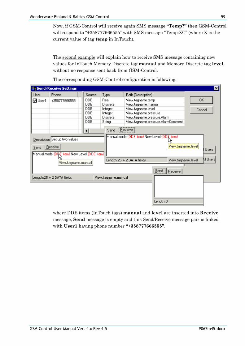
Wonderware Finland & Baltics GSM-Control 59
GSM-Control User Manual Ver. 4.x Rev 4.5 P067m45.docx
Now, if GSM-Control will receive again SMS message “Temp?” then GSM-Control
will respond to “+358777666555” with SMS message “Temp:XC” (where X is the
current value of tag temp in InTouch).
The second example will explain how to receive SMS message containing new
values for InTouch Memory Discrete tag manual and Memory Discrete tag level,
without no response sent back from GSM-Control.
The corresponding GSM-Control configuration is following:
where DDE items (InTouch tags) manual and level are inserted into Receive
message, Send message is empty and this Send/Receive message pair is linked
with User1 having phone number “+358777666555”.
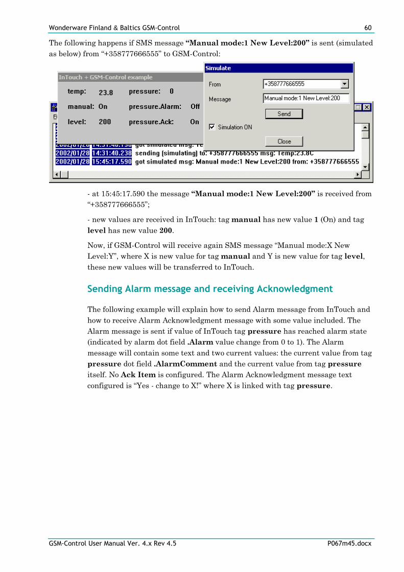
Wonderware Finland & Baltics GSM-Control 60
GSM-Control User Manual Ver. 4.x Rev 4.5 P067m45.docx
The following happens if SMS message “Manual mode:1 New Level:200” is sent (simulated
as below) from “+358777666555” to GSM-Control:
- at 15:45:17.590 the message “Manual mode:1 New Level:200” is received from
“+358777666555”;
- new values are received in InTouch: tag manual has new value 1 (On) and tag
level has new value 200.
Now, if GSM-Control will receive again SMS message “Manual mode:X New
Level:Y”, where X is new value for tag manual and Y is new value for tag level,
these new values will be transferred to InTouch.
Sending Alarm message and receiving Acknowledgment
The following example will explain how to send Alarm message from InTouch and
how to receive Alarm Acknowledgment message with some value included. The
Alarm message is sent if value of InTouch tag pressure has reached alarm state
(indicated by alarm dot field .Alarm value change from 0 to 1). The Alarm
message will contain some text and two current values: the current value from tag
pressure dot field .AlarmComment and the current value from tag pressure
itself. No Ack Item is configured. The Alarm Acknowledgment message text
configured is “Yes - change to X!” where X is linked with tag pressure.
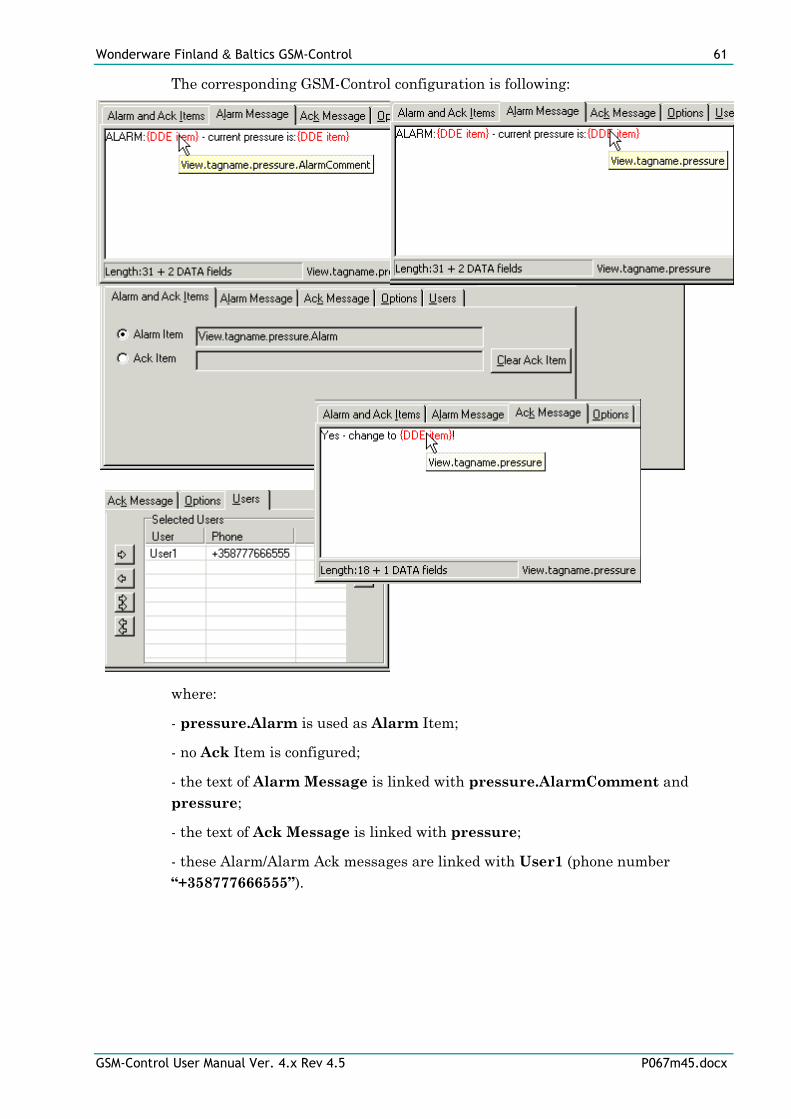
Wonderware Finland & Baltics GSM-Control 61
GSM-Control User Manual Ver. 4.x Rev 4.5 P067m45.docx
The corresponding GSM-Control configuration is following:
where:
- pressure.Alarm is used as Alarm Item;
- no Ack Item is configured;
- the text of Alarm Message is linked with pressure.AlarmComment and
pressure;
- the text of Ack Message is linked with pressure;
- these Alarm/Alarm Ack messages are linked with User1 (phone number
“+358777666555”).
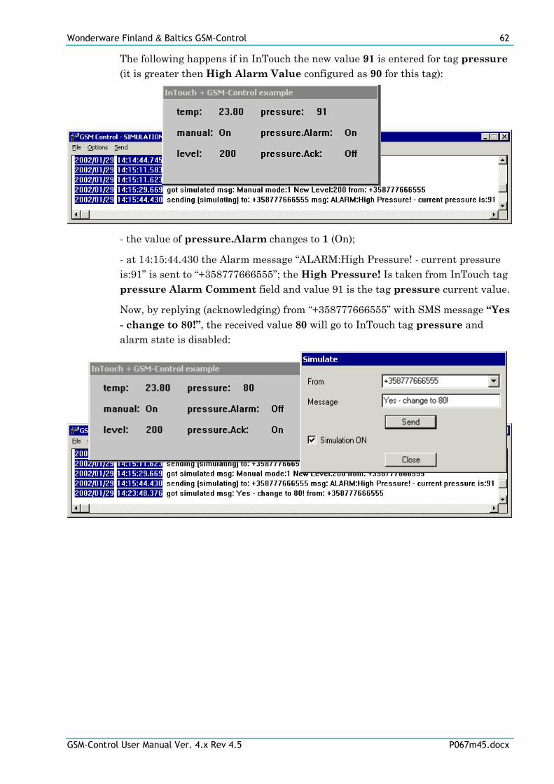
Wonderware Finland & Baltics GSM-Control 62
GSM-Control User Manual Ver. 4.x Rev 4.5 P067m45.docx
The following happens if in InTouch the new value 91 is entered for tag pressure
(it is greater then High Alarm Value configured as 90 for this tag):
- the value of pressure.Alarm changes to 1 (On);
- at 14:15:44.430 the Alarm message “ALARM:High Pressure! - current pressure
is:91” is sent to “+358777666555”; the High Pressure! Is taken from InTouch tag
pressure Alarm Comment field and value 91 is the tag pressure current value.
Now, by replying (acknowledging) from “+358777666555” with SMS message “Yes
- change to 80!”, the received value 80 will go to InTouch tag pressure and
alarm state is disabled:
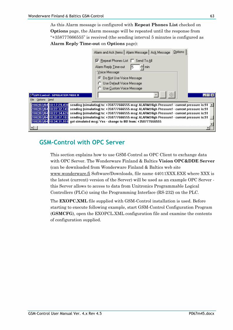
Wonderware Finland & Baltics GSM-Control 63
GSM-Control User Manual Ver. 4.x Rev 4.5 P067m45.docx
As this Alarm message is configured with Repeat Phones List checked on
Options page, the Alarm message will be repeated until the response from
“+358777666555” is received (the sending interval 5 minutes is configured as
Alarm Reply Time-out on Options page):
GSM-Control with OPC Server
This section explains how to use GSM-Control as OPC Client to exchange data
with OPC Server. The Wonderware Finland & Baltics Vision OPC&DDE Server
(can be downloaded from Wonderware Finland & Baltics web site
www.wonderware.fi Software/Downloads, file name 44011XXX.EXE where XXX is
the latest (current) version of the Server) will be used as an example OPC Server -
this Server allows to access to data from Unitronics Programmable Logical
Controllers (PLCs) using the Programming Interface (RS-232) on the PLC.
The EXOPC.XML file supplied with GSM-Control installation is used. Before
starting to execute following example, start GSM-Control Configuration Program
(GSMCFG), open the EXOPCL.XML configuration file and examine the contents
of configuration supplied.
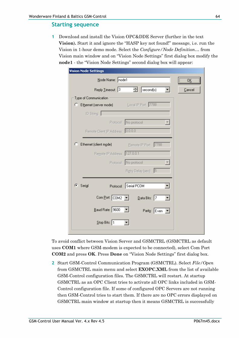
Wonderware Finland & Baltics GSM-Control 64
GSM-Control User Manual Ver. 4.x Rev 4.5 P067m45.docx
Starting sequence
1 Download and install the Vision OPC&DDE Server (further in the text
Vision). Start it and ignore the “HASP key not found!” message, i.e. run the
Vision in 1-hour demo mode. Select the Configure/Node Definition… from
Vision main window and on “Vision Node Settings” first dialog box modify the
node1 - the “Vision Node Settings” second dialog box will appear:
To avoid conflict between Vision Server and GSMCTRL (GSMCTRL as default
uses COM1 where GSM-modem is expected to be connected), select Com Port
COM2 and press OK. Press Done on “Vision Node Settings” first dialog box.
2 Start GSM-Control Communication Program (GSMCTRL). Select File/Open
from GSMCTRL main menu and select EXOPC.XML from the list of available
GSM-Control configuration files. The GSMCTRL will restart. At startup
GSMCTRL as an OPC Client tries to activate all OPC links included in GSM-
Control configuration file. If some of configured OPC Servers are not running
then GSM-Control tries to start them. If there are no OPC errors displayed on
GSMCTRL main window at startup then it means GSMCTRL is successfully
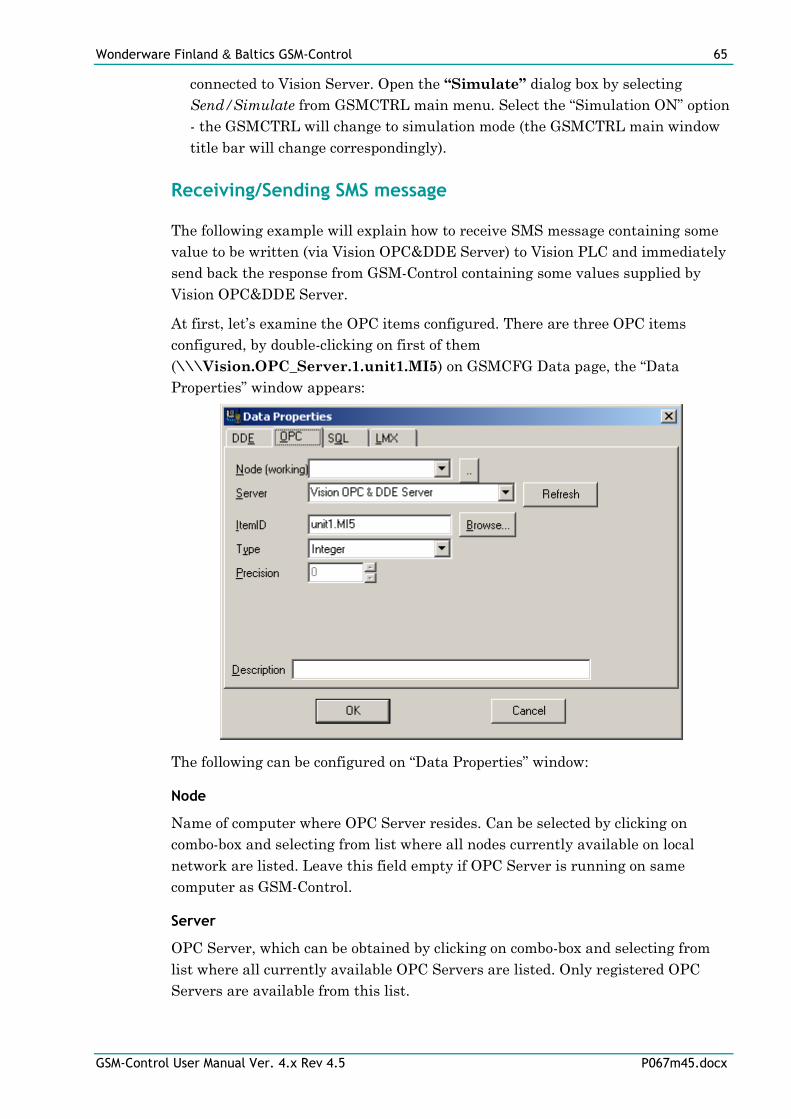
Wonderware Finland & Baltics GSM-Control 65
GSM-Control User Manual Ver. 4.x Rev 4.5 P067m45.docx
connected to Vision Server. Open the “Simulate” dialog box by selecting
Send/Simulate from GSMCTRL main menu. Select the “Simulation ON” option
- the GSMCTRL will change to simulation mode (the GSMCTRL main window
title bar will change correspondingly).
Receiving/Sending SMS message
The following example will explain how to receive SMS message containing some
value to be written (via Vision OPC&DDE Server) to Vision PLC and immediately
send back the response from GSM-Control containing some values supplied by
Vision OPC&DDE Server.
At first, let’s examine the OPC items configured. There are three OPC items
configured, by double-clicking on first of them
(\\\Vision.OPC_Server.1.unit1.MI5) on GSMCFG Data page, the “Data
Properties” window appears:
The following can be configured on “Data Properties” window:
Node
Name of computer where OPC Server resides. Can be selected by clicking on
combo-box and selecting from list where all nodes currently available on local
network are listed. Leave this field empty if OPC Server is running on same
computer as GSM-Control.
Server
OPC Server, which can be obtained by clicking on combo-box and selecting from
list where all currently available OPC Servers are listed. Only registered OPC
Servers are available from this list.
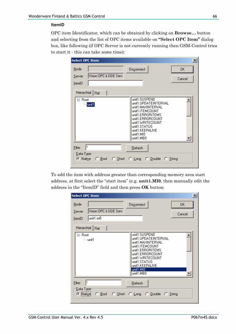
Wonderware Finland & Baltics GSM-Control 66
GSM-Control User Manual Ver. 4.x Rev 4.5 P067m45.docx
ItemID
OPC item Identificator, which can be obtained by clicking on Browse… button
and selecting from the list of OPC items available on “Select OPC Item” dialog
box, like following (if OPC Server is not currently running then GSM-Control tries
to start it - this can take some time):
To add the item with address greater than corresponding memory area start
address, at first select the “start item” (e.g. unit1.MI0, then manually edit the
address in the “ItemID” field and then press OK button:
Wonderware Finland & Baltics GSM-Control 67
GSM-Control User Manual Ver. 4.x Rev 4.5 P067m45.docx
Type
There are following types available: Integer, Real, Discrete and String, the
corresponding OPC native types are listed below (OPC values are in the VARIANT
format). The appropriate type can be selected by clicking mouse left button on
combo box:
- Integer (default selection) - signed 32-bit integer, range of values from -
2147483648 to 214748367; the corresponding OPC native types are VT_I4 and
VT_I2;
- Real - 32-bit floating (decimal) point, value may be between ±3.4e38; the
corresponding OPC native types are VT_R4 and VT_R8;
- Discrete - discrete with a value of either 0 (False, Off) or 1 (True, On); the
corresponding OPC native type is VT_BOOL;
- Message - text string that can be up to 131 characters long; the corresponding
OPC native type is VT_BSTR.
Precision
This field is accessible only for Real and String types:
- if Type is Real then Precision field is used to enter the number of digits after
decimal point. The default Precision is 0;
- if Type is String then Precision field is used to enter the maximum length of
string.
The Type and Precision fields are used to format the values of Data items in Send
and Alarm messages to be sent from GSM-Control. For example, if Type Real and
Precision 1 is used then following values will be sent from GSM-Control depending
on actual value, for example:
- if actual value is 24.7 then SMS message sent from GSM-Control will contain
“24.7”;
- if actual value is 24.74 then SMS message sent from GSM-Control will contain
“24.7”;
- if actual value is 24.75 then SMS message sent from GSM-Control will contain
“24.8”;
- if actual value is 24 then SMS message sent from GSM-Control will contain
“24.0”.
Description
Any desired description of OPC item can be entered here and correspondingly it
will be displayed on GSMCFG main window “Data” page “Path (Description)” field
for this OPC item.
If Description field is empty then on GSMCFG main window “Data” page this
OPC item “Path (Description)” field will be filled with Path, which will contain
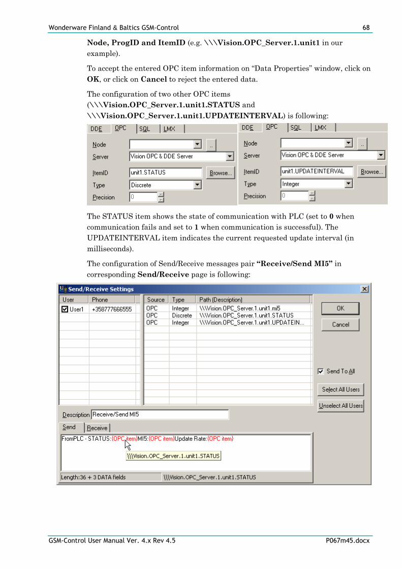
Wonderware Finland & Baltics GSM-Control 68
GSM-Control User Manual Ver. 4.x Rev 4.5 P067m45.docx
Node, ProgID and ItemID (e.g. \\\Vision.OPC_Server.1.unit1 in our
example).
To accept the entered OPC item information on “Data Properties” window, click on
OK, or click on Cancel to reject the entered data.
The configuration of two other OPC items
(\\\Vision.OPC_Server.1.unit1.STATUS and
\\\Vision.OPC_Server.1.unit1.UPDATEINTERVAL) is following:
The STATUS item shows the state of communication with PLC (set to 0 when
communication fails and set to 1 when communication is successful). The
UPDATEINTERVAL item indicates the current requested update interval (in
milliseconds).
The configuration of Send/Receive messages pair “Receive/Send MI5” in
corresponding Send/Receive page is following:
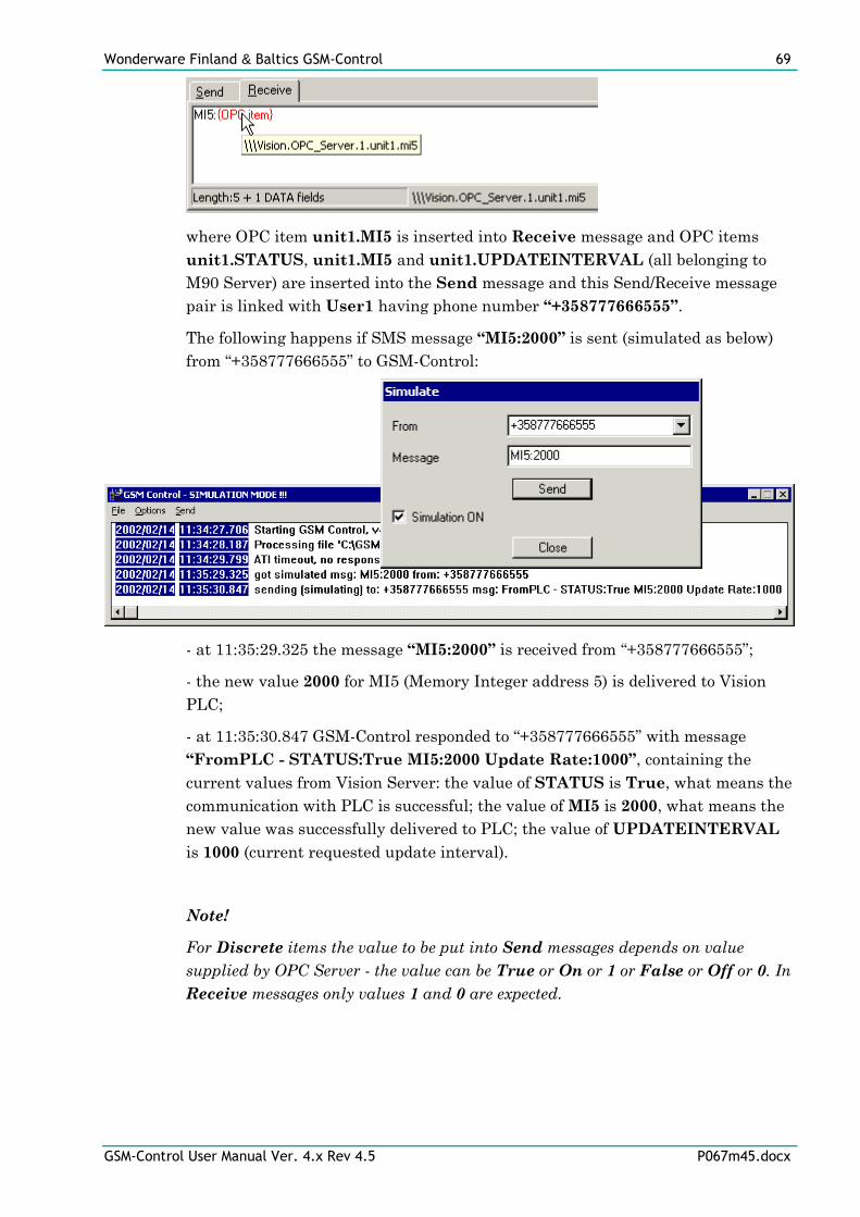
Wonderware Finland & Baltics GSM-Control 69
GSM-Control User Manual Ver. 4.x Rev 4.5 P067m45.docx
where OPC item unit1.MI5 is inserted into Receive message and OPC items
unit1.STATUS, unit1.MI5 and unit1.UPDATEINTERVAL (all belonging to
M90 Server) are inserted into the Send message and this Send/Receive message
pair is linked with User1 having phone number “+358777666555”.
The following happens if SMS message “MI5:2000” is sent (simulated as below)
from “+358777666555” to GSM-Control:
- at 11:35:29.325 the message “MI5:2000” is received from “+358777666555”;
- the new value 2000 for MI5 (Memory Integer address 5) is delivered to Vision
PLC;
- at 11:35:30.847 GSM-Control responded to “+358777666555” with message
“FromPLC - STATUS:True MI5:2000 Update Rate:1000”, containing the
current values from Vision Server: the value of STATUS is True, what means the
communication with PLC is successful; the value of MI5 is 2000, what means the
new value was successfully delivered to PLC; the value of UPDATEINTERVAL
is 1000 (current requested update interval).
Note!
For Discrete items the value to be put into Send messages depends on value
supplied by OPC Server - the value can be True or On or 1 or False or Off or 0. In
Receive messages only values 1 and 0 are expected.
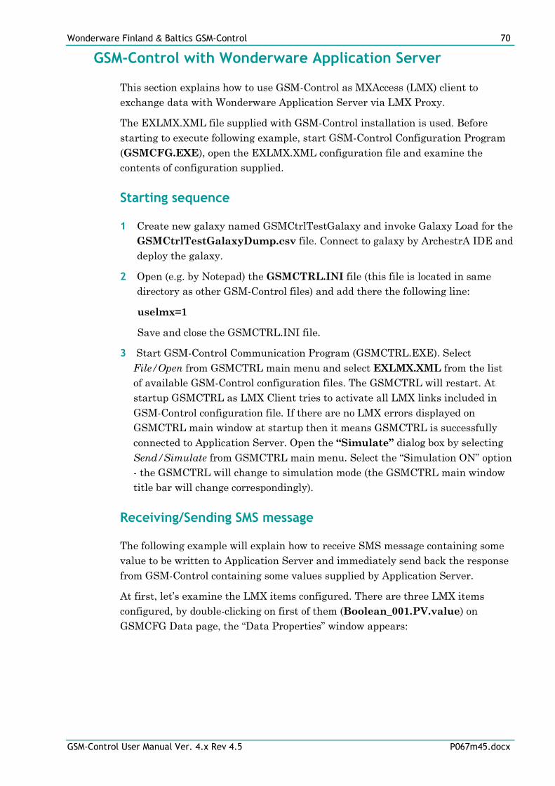
Wonderware Finland & Baltics GSM-Control 70
GSM-Control User Manual Ver. 4.x Rev 4.5 P067m45.docx
GSM-Control with Wonderware Application Server
This section explains how to use GSM-Control as MXAccess (LMX) client to
exchange data with Wonderware Application Server via LMX Proxy.
The EXLMX.XML file supplied with GSM-Control installation is used. Before
starting to execute following example, start GSM-Control Configuration Program
(GSMCFG.EXE), open the EXLMX.XML configuration file and examine the
contents of configuration supplied.
Starting sequence
1 Create new galaxy named GSMCtrlTestGalaxy and invoke Galaxy Load for the
GSMCtrlTestGalaxyDump.csv file. Connect to galaxy by ArchestrA IDE and
deploy the galaxy.
2 Open (e.g. by Notepad) the GSMCTRL.INI file (this file is located in same
directory as other GSM-Control files) and add there the following line:
uselmx=1
Save and close the GSMCTRL.INI file.
3 Start GSM-Control Communication Program (GSMCTRL.EXE). Select
File/Open from GSMCTRL main menu and select EXLMX.XML from the list
of available GSM-Control configuration files. The GSMCTRL will restart. At
startup GSMCTRL as LMX Client tries to activate all LMX links included in
GSM-Control configuration file. If there are no LMX errors displayed on
GSMCTRL main window at startup then it means GSMCTRL is successfully
connected to Application Server. Open the “Simulate” dialog box by selecting
Send/Simulate from GSMCTRL main menu. Select the “Simulation ON” option
- the GSMCTRL will change to simulation mode (the GSMCTRL main window
title bar will change correspondingly).
Receiving/Sending SMS message
The following example will explain how to receive SMS message containing some
value to be written to Application Server and immediately send back the response
from GSM-Control containing some values supplied by Application Server.
At first, let’s examine the LMX items configured. There are three LMX items
configured, by double-clicking on first of them (Boolean_001.PV.value) on
GSMCFG Data page, the “Data Properties” window appears:
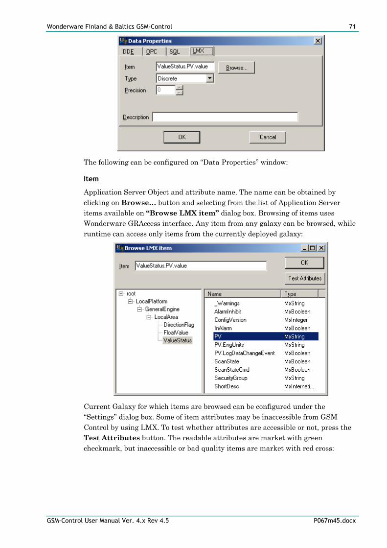
Wonderware Finland & Baltics GSM-Control 71
GSM-Control User Manual Ver. 4.x Rev 4.5 P067m45.docx
The following can be configured on “Data Properties” window:
Item
Application Server Object and attribute name. The name can be obtained by
clicking on Browse… button and selecting from the list of Application Server
items available on “Browse LMX item” dialog box. Browsing of items uses
Wonderware GRAccess interface. Any item from any galaxy can be browsed, while
runtime can access only items from the currently deployed galaxy:
Current Galaxy for which items are browsed can be configured under the
“Settings” dialog box. Some of item attributes may be inaccessible from GSM
Control by using LMX. To test whether attributes are accessible or not, press the
Test Attributes button. The readable attributes are market with green
checkmark, but inaccessible or bad quality items are market with red cross:
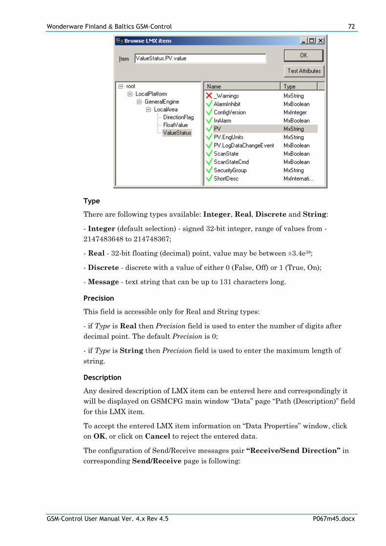
Wonderware Finland & Baltics GSM-Control 72
GSM-Control User Manual Ver. 4.x Rev 4.5 P067m45.docx
Type
There are following types available: Integer, Real, Discrete and String:
- Integer (default selection) - signed 32-bit integer, range of values from -
2147483648 to 214748367;
- Real - 32-bit floating (decimal) point, value may be between ±3.4e38;
- Discrete - discrete with a value of either 0 (False, Off) or 1 (True, On);
- Message - text string that can be up to 131 characters long.
Precision
This field is accessible only for Real and String types:
- if Type is Real then Precision field is used to enter the number of digits after
decimal point. The default Precision is 0;
- if Type is String then Precision field is used to enter the maximum length of
string.
Description
Any desired description of LMX item can be entered here and correspondingly it
will be displayed on GSMCFG main window “Data” page “Path (Description)” field
for this LMX item.
To accept the entered LMX item information on “Data Properties” window, click
on OK, or click on Cancel to reject the entered data.
The configuration of Send/Receive messages pair “Receive/Send Direction” in
corresponding Send/Receive page is following:
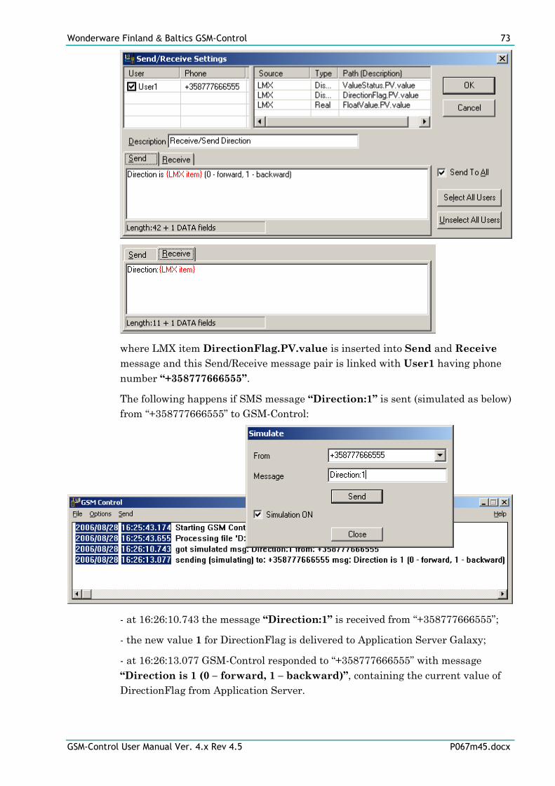
Wonderware Finland & Baltics GSM-Control 73
GSM-Control User Manual Ver. 4.x Rev 4.5 P067m45.docx
where LMX item DirectionFlag.PV.value is inserted into Send and Receive
message and this Send/Receive message pair is linked with User1 having phone
number “+358777666555”.
The following happens if SMS message “Direction:1” is sent (simulated as below)
from “+358777666555” to GSM-Control:
- at 16:26:10.743 the message “Direction:1” is received from “+358777666555”;
- the new value 1 for DirectionFlag is delivered to Application Server Galaxy;
- at 16:26:13.077 GSM-Control responded to “+358777666555” with message
“Direction is 1 (0 – forward, 1 – backward)”, containing the current value of
DirectionFlag from Application Server.
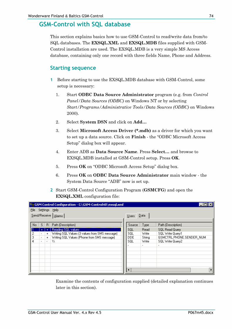
Wonderware Finland & Baltics GSM-Control 74
GSM-Control User Manual Ver. 4.x Rev 4.5 P067m45.docx
GSM-Control with SQL database
This section explains basics how to use GSM-Control to read/write data from/to
SQL databases. The EXSQL.XML and EXSQL.MDB files supplied with GSM-
Control installation are used. The EXSQL.MDB is a very simple MS Access
database, containing only one record with three fields Name, Phone and Address.
Starting sequence
1 Before starting to use the EXSQL.MDB database with GSM-Control, some
setup is necessary:
1. Start ODBC Data Source Administrator program (e.g. from Control
Panel/Data Sources (ODBC) on Windows NT or by selecting
Start/Programs/Administrative Tools/Data Sources (ODBC) on Windows
2000).
2. Select System DSN and click on Add…
3. Select Microsoft Access Driver (*.mdb) as a driver for which you want
to set up a data source. Click on Finish - the “ODBC Microsoft Access
Setup” dialog box will appear.
4. Enter ADB as Data Source Name. Press Select… and browse to
EXSQL.MDB installed at GSM-Control setup. Press OK.
5. Press OK on “ODBC Microsoft Access Setup” dialog box.
6. Press OK on ODBC Data Source Administrator main window - the
System Data Source “ADB” now is set up.
2 Start GSM-Control Configuration Program (GSMCFG) and open the
EXSQL.XML configuration file:
Examine the contents of configuration supplied (detailed explanation continues
later in this section).
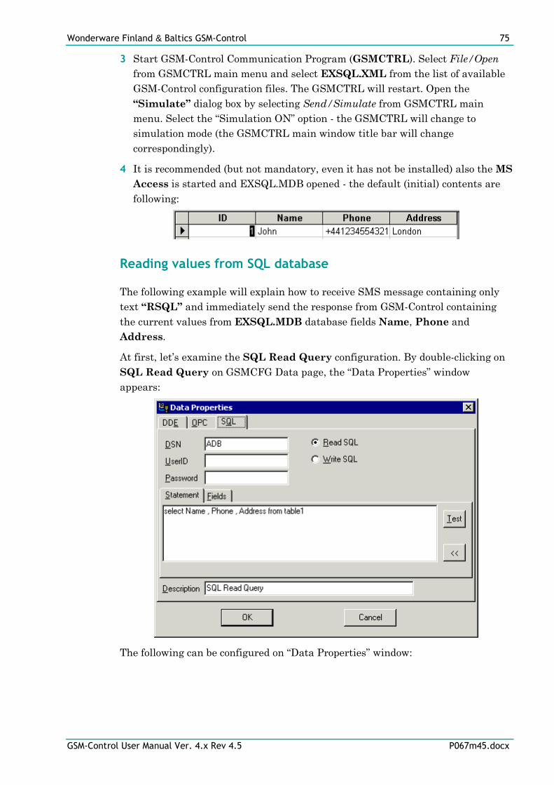
Wonderware Finland & Baltics GSM-Control 75
GSM-Control User Manual Ver. 4.x Rev 4.5 P067m45.docx
3 Start GSM-Control Communication Program (GSMCTRL). Select File/Open
from GSMCTRL main menu and select EXSQL.XML from the list of available
GSM-Control configuration files. The GSMCTRL will restart. Open the
“Simulate” dialog box by selecting Send/Simulate from GSMCTRL main
menu. Select the “Simulation ON” option - the GSMCTRL will change to
simulation mode (the GSMCTRL main window title bar will change
correspondingly).
4 It is recommended (but not mandatory, even it has not be installed) also the MS
Access is started and EXSQL.MDB opened - the default (initial) contents are
following:
Reading values from SQL database
The following example will explain how to receive SMS message containing only
text “RSQL” and immediately send the response from GSM-Control containing
the current values from EXSQL.MDB database fields Name, Phone and
Address.
At first, let’s examine the SQL Read Query configuration. By double-clicking on
SQL Read Query on GSMCFG Data page, the “Data Properties” window
appears:
The following can be configured on “Data Properties” window:
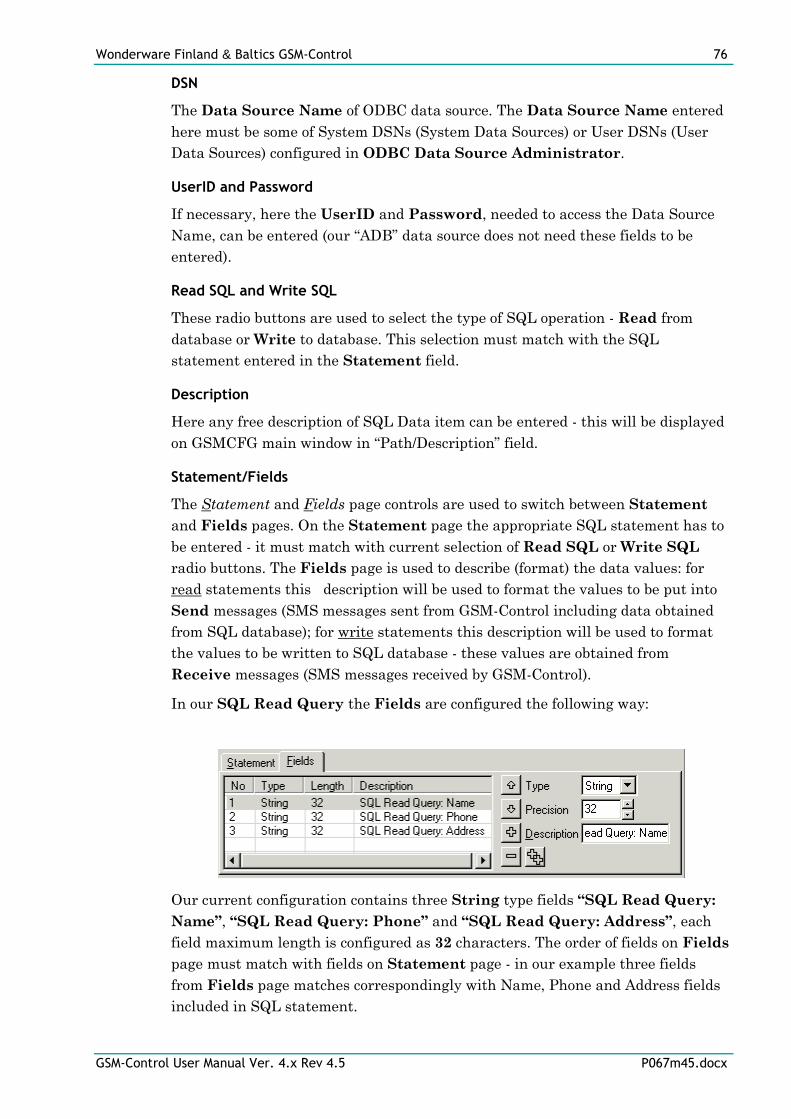
Wonderware Finland & Baltics GSM-Control 76
GSM-Control User Manual Ver. 4.x Rev 4.5 P067m45.docx
DSN
The Data Source Name of ODBC data source. The Data Source Name entered
here must be some of System DSNs (System Data Sources) or User DSNs (User
Data Sources) configured in ODBC Data Source Administrator.
UserID and Password
If necessary, here the UserID and Password, needed to access the Data Source
Name, can be entered (our “ADB” data source does not need these fields to be
entered).
Read SQL and Write SQL
These radio buttons are used to select the type of SQL operation - Read from
database or Write to database. This selection must match with the SQL
statement entered in the Statement field.
Description
Here any free description of SQL Data item can be entered - this will be displayed
on GSMCFG main window in “Path/Description” field.
Statement/Fields
The Statement and Fields page controls are used to switch between Statement
and Fields pages. On the Statement page the appropriate SQL statement has to
be entered - it must match with current selection of Read SQL or Write SQL
radio buttons. The Fields page is used to describe (format) the data values: for
read statements this description will be used to format the values to be put into
Send messages (SMS messages sent from GSM-Control including data obtained
from SQL database); for write statements this description will be used to format
the values to be written to SQL database - these values are obtained from
Receive messages (SMS messages received by GSM-Control).
In our SQL Read Query the Fields are configured the following way:
Our current configuration contains three String type fields “SQL Read Query:
Name”, “SQL Read Query: Phone” and “SQL Read Query: Address”, each
field maximum length is configured as 32 characters. The order of fields on Fields
page must match with fields on Statement page - in our example three fields
from Fields page matches correspondingly with Name, Phone and Address fields
included in SQL statement.
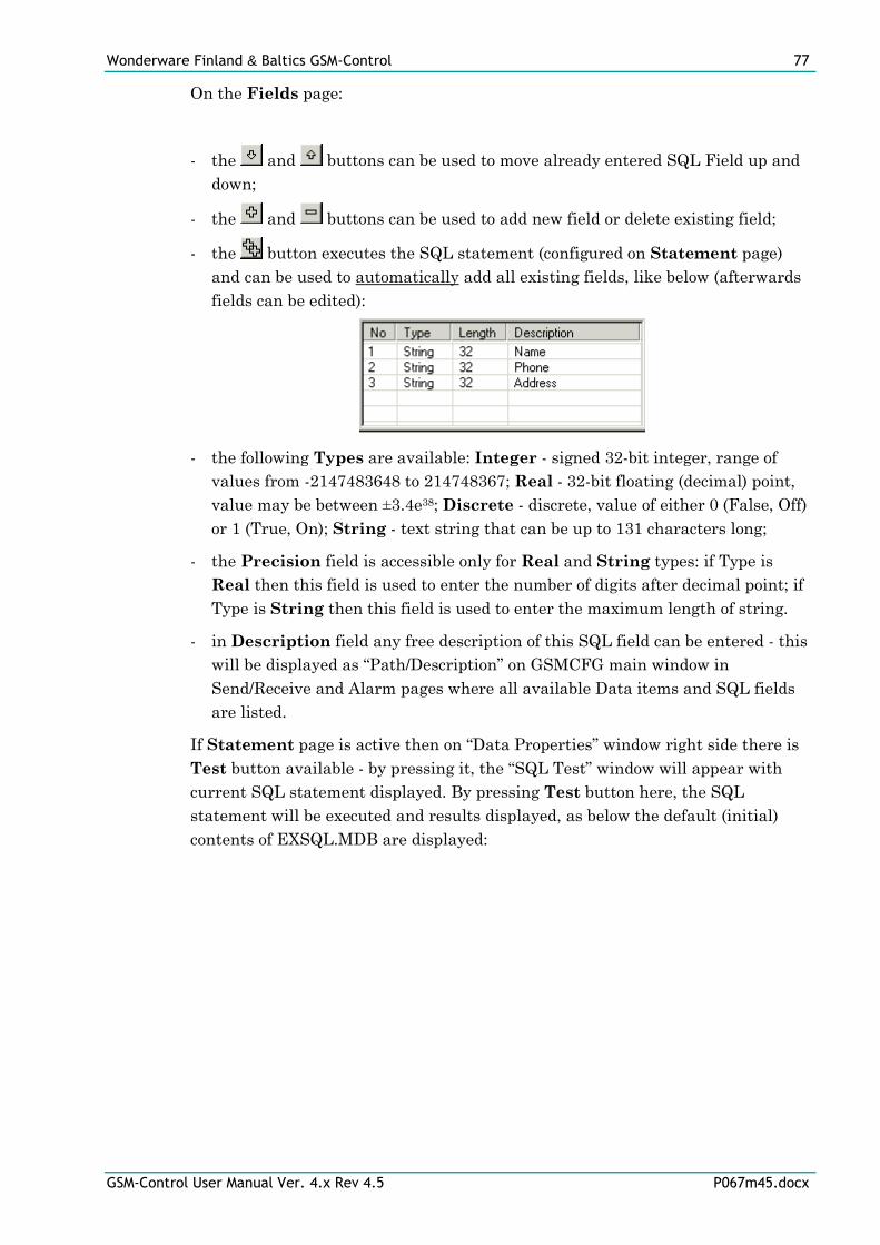
Wonderware Finland & Baltics GSM-Control 77
GSM-Control User Manual Ver. 4.x Rev 4.5 P067m45.docx
On the Fields page:
- the and buttons can be used to move already entered SQL Field up and
down;
- the and buttons can be used to add new field or delete existing field;
- the button executes the SQL statement (configured on Statement page)
and can be used to automatically add all existing fields, like below (afterwards
fields can be edited):
- the following Types are available: Integer - signed 32-bit integer, range of
values from -2147483648 to 214748367; Real - 32-bit floating (decimal) point,
value may be between ±3.4e38; Discrete - discrete, value of either 0 (False, Off)
or 1 (True, On); String - text string that can be up to 131 characters long;
- the Precision field is accessible only for Real and String types: if Type is
Real then this field is used to enter the number of digits after decimal point; if
Type is String then this field is used to enter the maximum length of string.
- in Description field any free description of this SQL field can be entered - this
will be displayed as “Path/Description” on GSMCFG main window in
Send/Receive and Alarm pages where all available Data items and SQL fields
are listed.
If Statement page is active then on “Data Properties” window right side there is
Test button available - by pressing it, the “SQL Test” window will appear with
current SQL statement displayed. By pressing Test button here, the SQL
statement will be executed and results displayed, as below the default (initial)
contents of EXSQL.MDB are displayed:
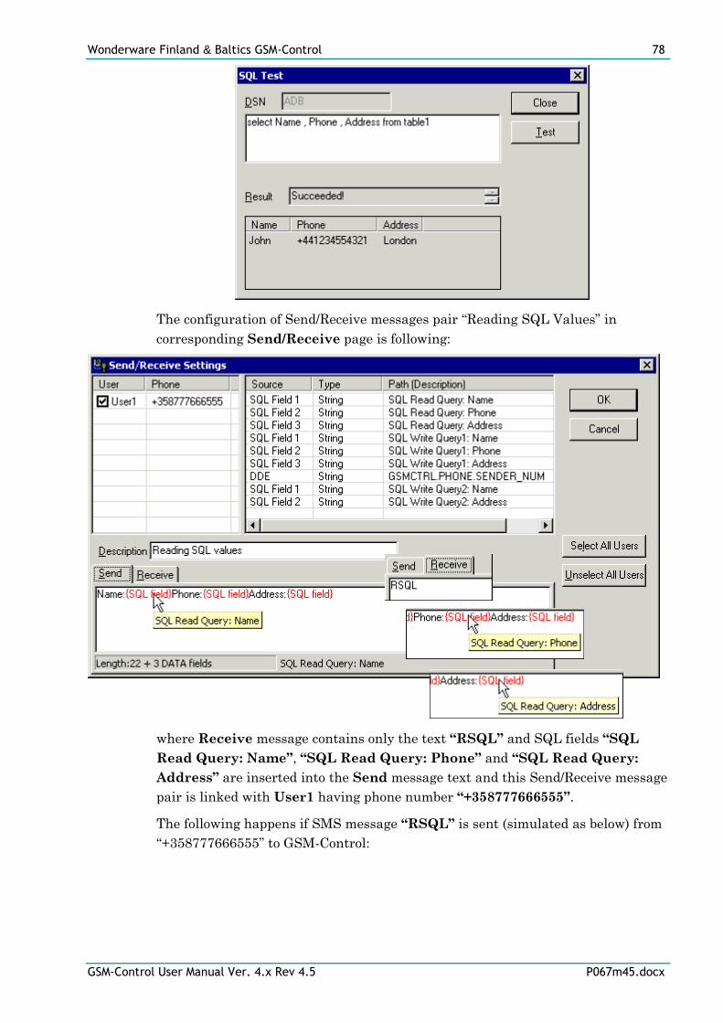
Wonderware Finland & Baltics GSM-Control 78
GSM-Control User Manual Ver. 4.x Rev 4.5 P067m45.docx
The configuration of Send/Receive messages pair “Reading SQL Values” in
corresponding Send/Receive page is following:
where Receive message contains only the text “RSQL” and SQL fields “SQL
Read Query: Name”, “SQL Read Query: Phone” and “SQL Read Query:
Address” are inserted into the Send message text and this Send/Receive message
pair is linked with User1 having phone number “+358777666555”.
The following happens if SMS message “RSQL” is sent (simulated as below) from
“+358777666555” to GSM-Control:
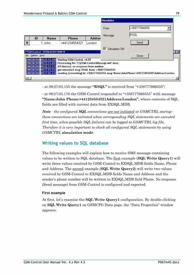
Wonderware Finland & Baltics GSM-Control 79
GSM-Control User Manual Ver. 4.x Rev 4.5 P067m45.docx
- at 09:27:03.155 the message “RSQL” is received from “+358777666555”;
- at 09:27:05.178 the GSM-Control responded to “+358777666555” with message
“Name:John Phone:+441234554321Address:London”, where contents of SQL
fields are filled with current data from EXSQL.MDB.
Note - the configured SQL connections are not initiated at GSMCTRL startup -
these connections are initiated when corresponding SQL statements are executed
first time, when possible SQL failures can be logged to GSMCTRL log file.
Therefore it is very important to check all configured SQL statements by using
GSMCTRL simulation mode.
Writing values to SQL database
The following examples will explain how to receive SMS message containing
values to be written to SQL database. The first example (SQL Write Query1) will
write three values received by GSM-Control to EXSQL.MDB fields Name, Phone
and Address. The second example (SQL Write Query2) will write two values
received by GSM-Control to EXSQL.MDB fields Name and Address and the
sender’s phone number will be written to EXSQL.MDB field Phone. No response
(Send message) from GSM-Control is configured and expected.
First example
At first, let’s examine the SQL Write Query1 configuration. By double-clicking
on SQL Write Query1 on GSMCFG Data page, the “Data Properties” window
appears:

Wonderware Finland & Baltics GSM-Control 80
GSM-Control User Manual Ver. 4.x Rev 4.5 P067m45.docx
The SQL Write Query1 is configured with DSN ADB, the SQL operation is
Write SQL and there are three String type fields “SQL Write Query1: Name”,
“SQL Write Query1: Phone” and “SQL Write Query1: Address”, each field
maximum length is 32 characters. The order of fields on Fields page must match
with fields on Statement page - in our example three fields from Fields page
matches correspondingly with Name, Phone and Address fields included in SQL
statement and the “?” (quotation mark) is used to specify the location in SQL
statement where the new values (from SMS message received) will be put before
executing the SQL statement.
If Statement page is active then on “Data Properties” window right side there is a
Test button available - by pressing it, the “SQL Test” window will appear with
current SQL statement displayed. By pressing Test button here, the “Enter String
value” dialog box will appear as many times as there are “?” signs included in the
SQL statement and “?” sign will be correspondingly substituted with value
entered, like following:
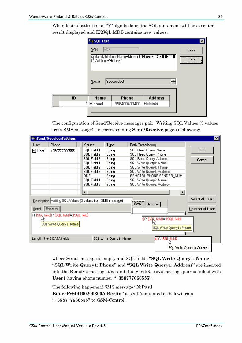
Wonderware Finland & Baltics GSM-Control 81
GSM-Control User Manual Ver. 4.x Rev 4.5 P067m45.docx
When last substitution of “?” sign is done, the SQL statement will be executed,
result displayed and EXSQL.MDB contains new values:
The configuration of Send/Receive messages pair “Writing SQL Values (3 values
from SMS message)” in corresponding Send/Receive page is following:
where Send message is empty and SQL fields “SQL Write Query1: Name”,
“SQL Write Query1: Phone” and “SQL Write Query1: Address” are inserted
into the Receive message text and this Send/Receive message pair is linked with
User1 having phone number “+358777666555”.
The following happens if SMS message “N:Paul
BauerP:+49100200300A:Berlin” is sent (simulated as below) from
“+358777666555” to GSM-Control:
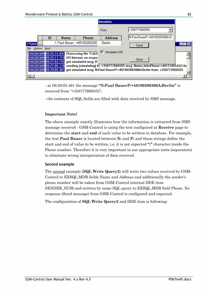
Wonderware Finland & Baltics GSM-Control 82
GSM-Control User Manual Ver. 4.x Rev 4.5 P067m45.docx
- at 09:29:05.461 the message “N:Paul BauerP:+49100200300A:Berlin” is
received from “+358777666555”;
- the contents of SQL fields are filled with data received by SMS message.
Important Note!
The above example exactly illustrates how the information is extracted from SMS
message received - GSM-Control is using the text configured at Receive page to
determine the start and end of each value to be written to database. For example,
the text Paul Bauer is located between N: and P: and these strings define the
start and end of value to be written, i.e. it is not expected “:” character inside the
Phone number. Therefore it is very important to use appropriate texts (separators)
to eliminate wrong interpretation of data received.
Second example
The second example (SQL Write Query2) will write two values received by GSM-
Control to EXSQL.MDB fields Name and Address and additionally the sender’s
phone number will be taken from GSM-Control internal DDE item
SENDER_NUM and written by same SQL query to EXSQL.MDB field Phone. No
response (Send message) from GSM-Control is configured and expected.
The configuration of SQL Write Query2 and DDE item is following:
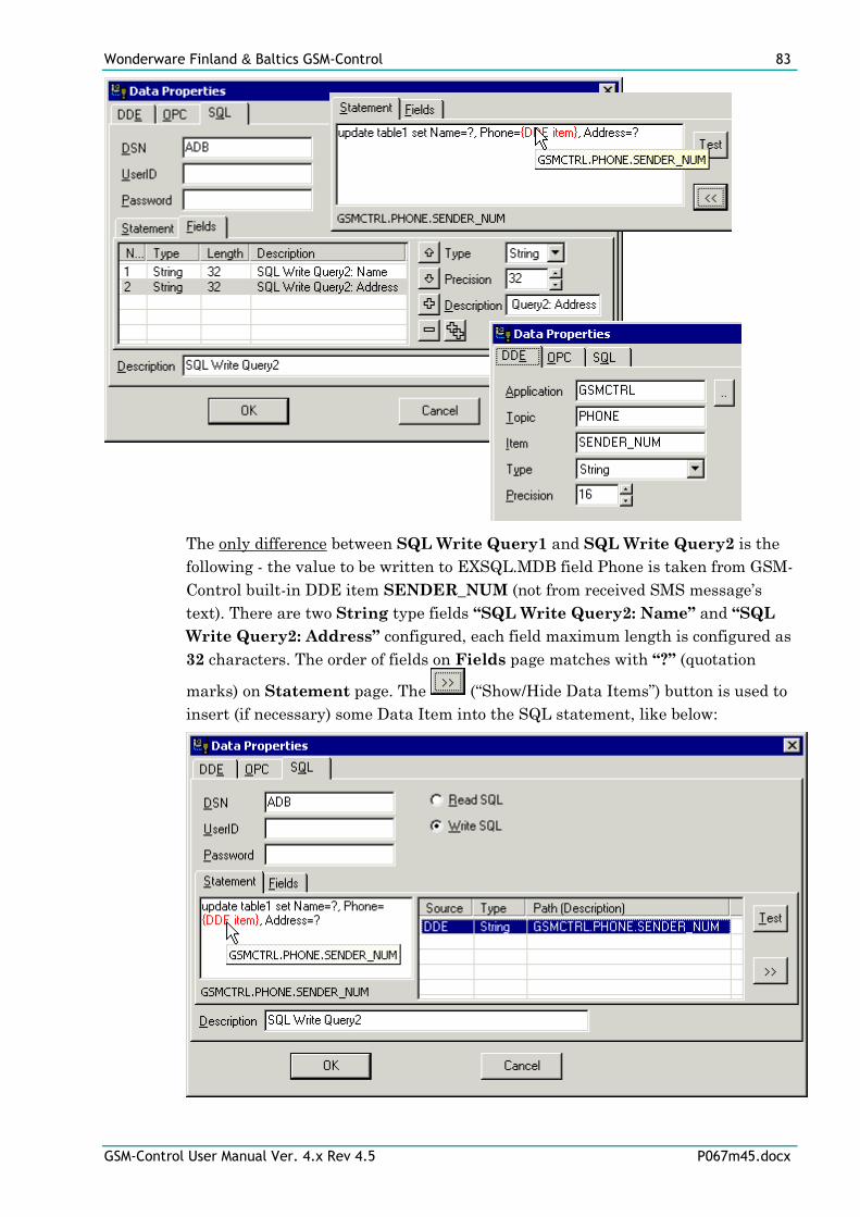
Wonderware Finland & Baltics GSM-Control 83
GSM-Control User Manual Ver. 4.x Rev 4.5 P067m45.docx
The only difference between SQL Write Query1 and SQL Write Query2 is the
following - the value to be written to EXSQL.MDB field Phone is taken from GSM-
Control built-in DDE item SENDER_NUM (not from received SMS message’s
text). There are two String type fields “SQL Write Query2: Name” and “SQL
Write Query2: Address” configured, each field maximum length is configured as
32 characters. The order of fields on Fields page matches with “?” (quotation
marks) on Statement page. The (“Show/Hide Data Items”) button is used to
insert (if necessary) some Data Item into the SQL statement, like below:
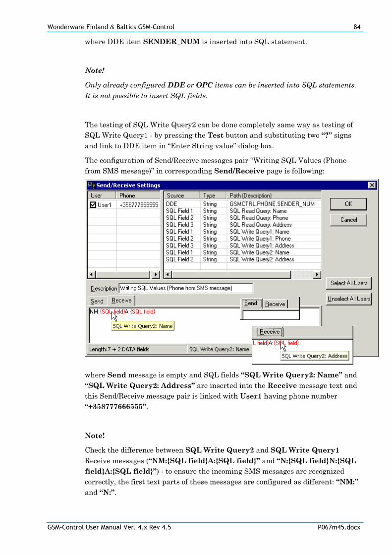
Wonderware Finland & Baltics GSM-Control 84
GSM-Control User Manual Ver. 4.x Rev 4.5 P067m45.docx
where DDE item SENDER_NUM is inserted into SQL statement.
Note!
Only already configured DDE or OPC items can be inserted into SQL statements.
It is not possible to insert SQL fields.
The testing of SQL Write Query2 can be done completely same way as testing of
SQL Write Query1 - by pressing the Test button and substituting two “?” signs
and link to DDE item in “Enter String value” dialog box.
The configuration of Send/Receive messages pair “Writing SQL Values (Phone
from SMS message)” in corresponding Send/Receive page is following:
where Send message is empty and SQL fields “SQL Write Query2: Name” and
“SQL Write Query2: Address” are inserted into the Receive message text and
this Send/Receive message pair is linked with User1 having phone number
“+358777666555”.
Note!
Check the difference between SQL Write Query2 and SQL Write Query1
Receive messages (“NM:{SQL field}A:{SQL field}” and “N:{SQL field}N:{SQL
field}A:{SQL field}”) - to ensure the incoming SMS messages are recognized
correctly, the first text parts of these messages are configured as different: “NM:”
and “N:”.
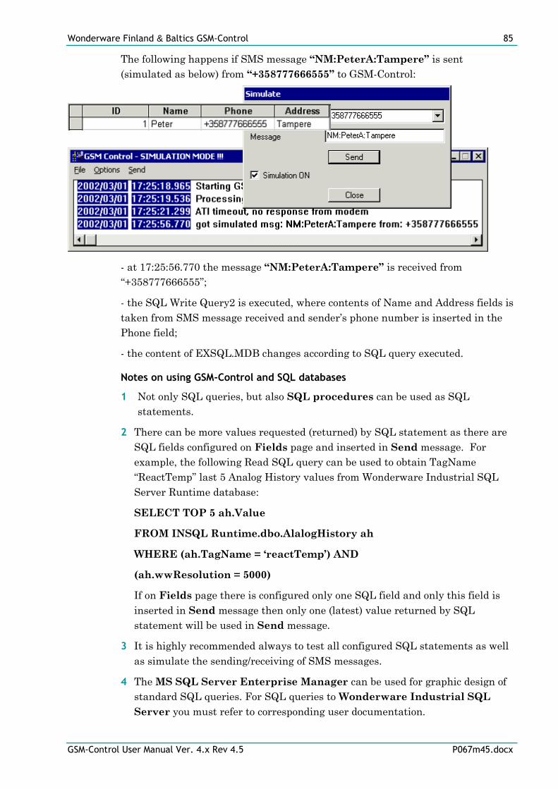
Wonderware Finland & Baltics GSM-Control 85
GSM-Control User Manual Ver. 4.x Rev 4.5 P067m45.docx
The following happens if SMS message “NM:PeterA:Tampere” is sent
(simulated as below) from “+358777666555” to GSM-Control:
- at 17:25:56.770 the message “NM:PeterA:Tampere” is received from
“+358777666555”;
- the SQL Write Query2 is executed, where contents of Name and Address fields is
taken from SMS message received and sender’s phone number is inserted in the
Phone field;
- the content of EXSQL.MDB changes according to SQL query executed.
Notes on using GSM-Control and SQL databases
1 Not only SQL queries, but also SQL procedures can be used as SQL
statements.
2 There can be more values requested (returned) by SQL statement as there are
SQL fields configured on Fields page and inserted in Send message. For
example, the following Read SQL query can be used to obtain TagName
“ReactTemp” last 5 Analog History values from Wonderware Industrial SQL
Server Runtime database:
SELECT TOP 5 ah.Value
FROM INSQL Runtime.dbo.AlalogHistory ah
WHERE (ah.TagName = ‘reactTemp’) AND
(ah.wwResolution = 5000)
If on Fields page there is configured only one SQL field and only this field is
inserted in Send message then only one (latest) value returned by SQL
statement will be used in Send message.
3 It is highly recommended always to test all configured SQL statements as well
as simulate the sending/receiving of SMS messages.
4 The MS SQL Server Enterprise Manager can be used for graphic design of
standard SQL queries. For SQL queries to Wonderware Industrial SQL
Server you must refer to corresponding user documentation.
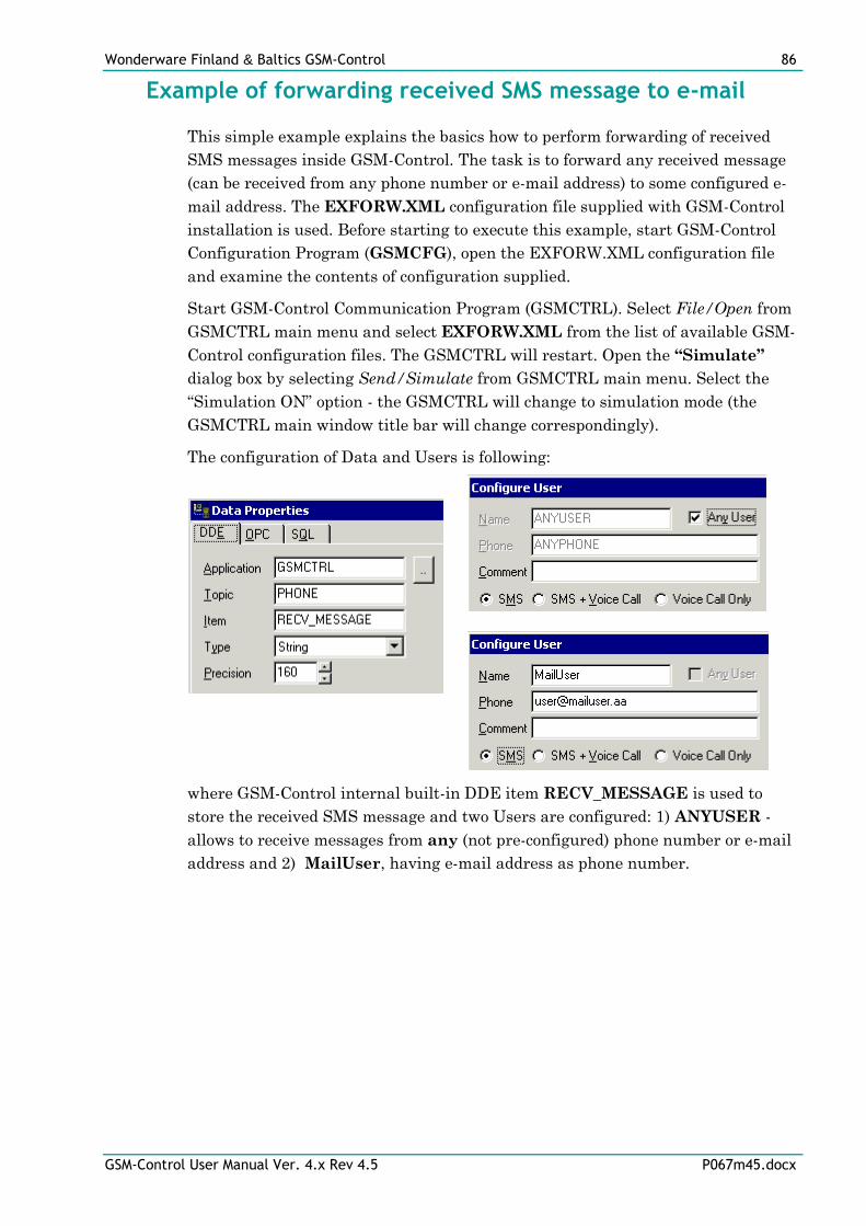
Wonderware Finland & Baltics GSM-Control 86
GSM-Control User Manual Ver. 4.x Rev 4.5 P067m45.docx
Example of forwarding received SMS message to e-mail
This simple example explains the basics how to perform forwarding of received
SMS messages inside GSM-Control. The task is to forward any received message
(can be received from any phone number or e-mail address) to some configured e-
mail address. The EXFORW.XML configuration file supplied with GSM-Control
installation is used. Before starting to execute this example, start GSM-Control
Configuration Program (GSMCFG), open the EXFORW.XML configuration file
and examine the contents of configuration supplied.
Start GSM-Control Communication Program (GSMCTRL). Select File/Open from
GSMCTRL main menu and select EXFORW.XML from the list of available GSM-
Control configuration files. The GSMCTRL will restart. Open the “Simulate”
dialog box by selecting Send/Simulate from GSMCTRL main menu. Select the
“Simulation ON” option - the GSMCTRL will change to simulation mode (the
GSMCTRL main window title bar will change correspondingly).
The configuration of Data and Users is following:
where GSM-Control internal built-in DDE item RECV_MESSAGE is used to
store the received SMS message and two Users are configured: 1) ANYUSER -
allows to receive messages from any (not pre-configured) phone number or e-mail
address and 2) MailUser, having e-mail address as phone number.
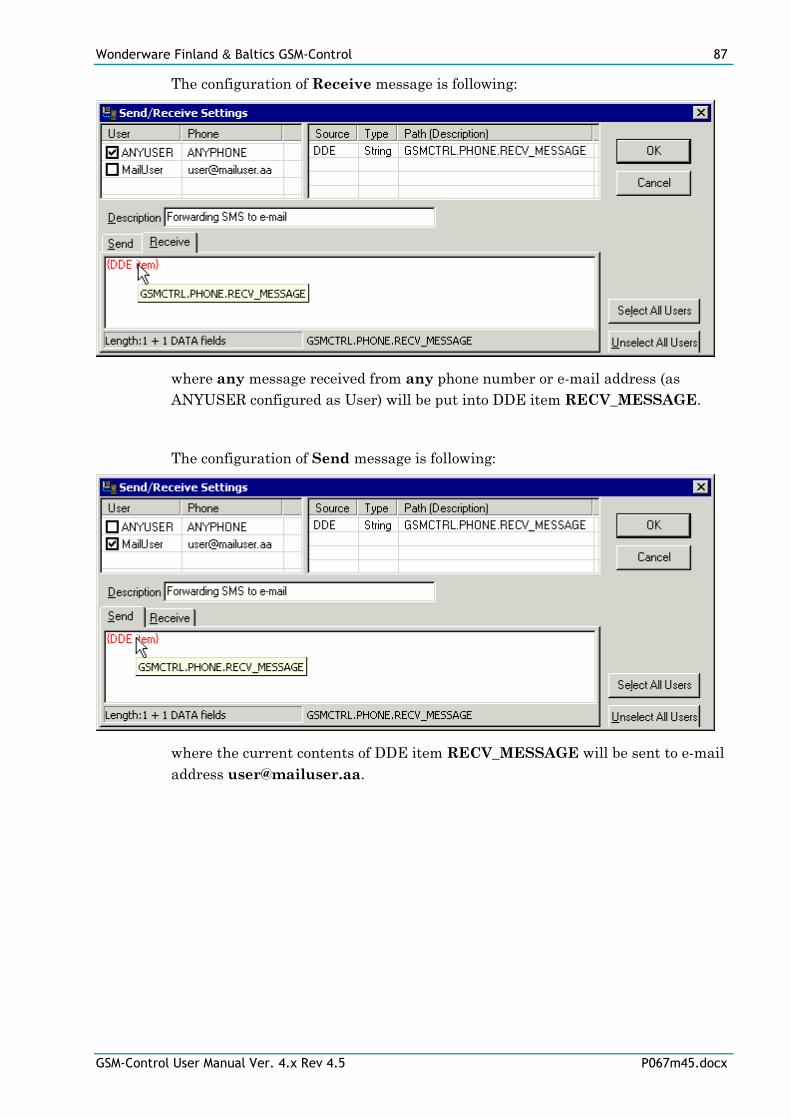
Wonderware Finland & Baltics GSM-Control 87
GSM-Control User Manual Ver. 4.x Rev 4.5 P067m45.docx
The configuration of Receive message is following:
where any message received from any phone number or e-mail address (as
ANYUSER configured as User) will be put into DDE item RECV_MESSAGE.
The configuration of Send message is following:
where the current contents of DDE item RECV_MESSAGE will be sent to e-mail
address [email protected].
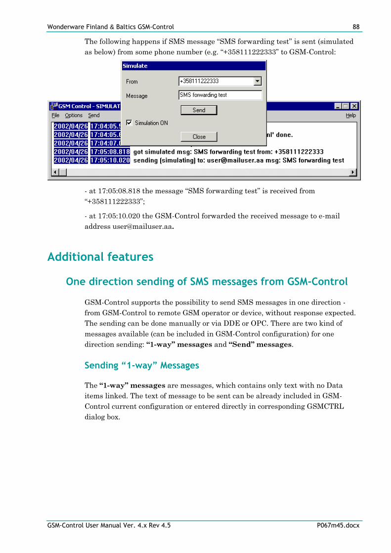
Wonderware Finland & Baltics GSM-Control 88
GSM-Control User Manual Ver. 4.x Rev 4.5 P067m45.docx
The following happens if SMS message “SMS forwarding test” is sent (simulated
as below) from some phone number (e.g. “+358111222333” to GSM-Control:
- at 17:05:08.818 the message “SMS forwarding test” is received from
“+358111222333”;
- at 17:05:10.020 the GSM-Control forwarded the received message to e-mail
address [email protected].
Additional features
One direction sending of SMS messages from GSM-Control
GSM-Control supports the possibility to send SMS messages in one direction -
from GSM-Control to remote GSM operator or device, without response expected.
The sending can be done manually or via DDE or OPC. There are two kind of
messages available (can be included in GSM-Control configuration) for one
direction sending: “1-way” messages and “Send” messages.
Sending “1-way” Messages
The “1-way” messages are messages, which contains only text with no Data
items linked. The text of message to be sent can be already included in GSM-
Control current configuration or entered directly in corresponding GSMCTRL
dialog box.
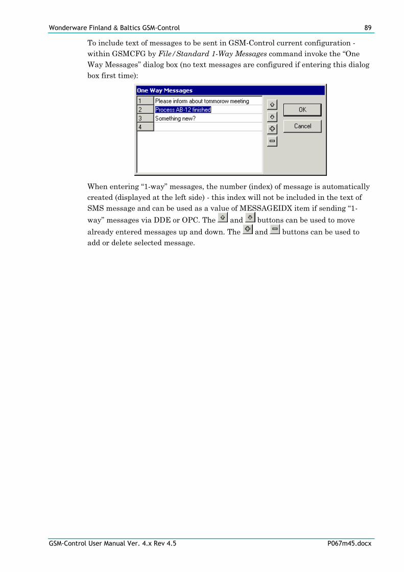
Wonderware Finland & Baltics GSM-Control 89
GSM-Control User Manual Ver. 4.x Rev 4.5 P067m45.docx
To include text of messages to be sent in GSM-Control current configuration -
within GSMCFG by File/Standard 1-Way Messages command invoke the “One
Way Messages” dialog box (no text messages are configured if entering this dialog
box first time):
When entering “1-way” messages, the number (index) of message is automatically
created (displayed at the left side) - this index will not be included in the text of
SMS message and can be used as a value of MESSAGEIDX item if sending “1-
way” messages via DDE or OPC. The and buttons can be used to move
already entered messages up and down. The and buttons can be used to
add or delete selected message.
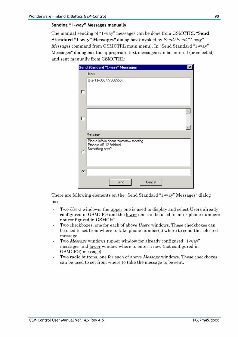
Wonderware Finland & Baltics GSM-Control 90
GSM-Control User Manual Ver. 4.x Rev 4.5 P067m45.docx
Sending “1-way” Messages manually
The manual sending of “1-way” messages can be done from GSMCTRL "Send
Standard “1-way” Messages" dialog box (invoked by Send/Send “1-way”
Messages command from GSMCTRL main menu). In "Send Standard “1-way”
Messages" dialog box the appropriate text messages can be entered (or selected)
and sent manually from GSMCTRL:
There are following elements on the "Send Standard “1-way” Messages" dialog
box:
- Two Users windows: the upper one is used to display and select Users already
configured in GSMCFG and the lower one can be used to enter phone numbers
not configured in GSMCFG.
- Two checkboxes, one for each of above Users windows. These checkboxes can
be used to set from where to take phone number(s) where to send the selected
message.
- Two Message windows (upper window for already configured “1-way”
messages and lower window where to enter a new (not configured in
GSMCFG) message).
- Two radio buttons, one for each of above Message windows. These checkboxes
can be used to set from where to take the message to be sent.
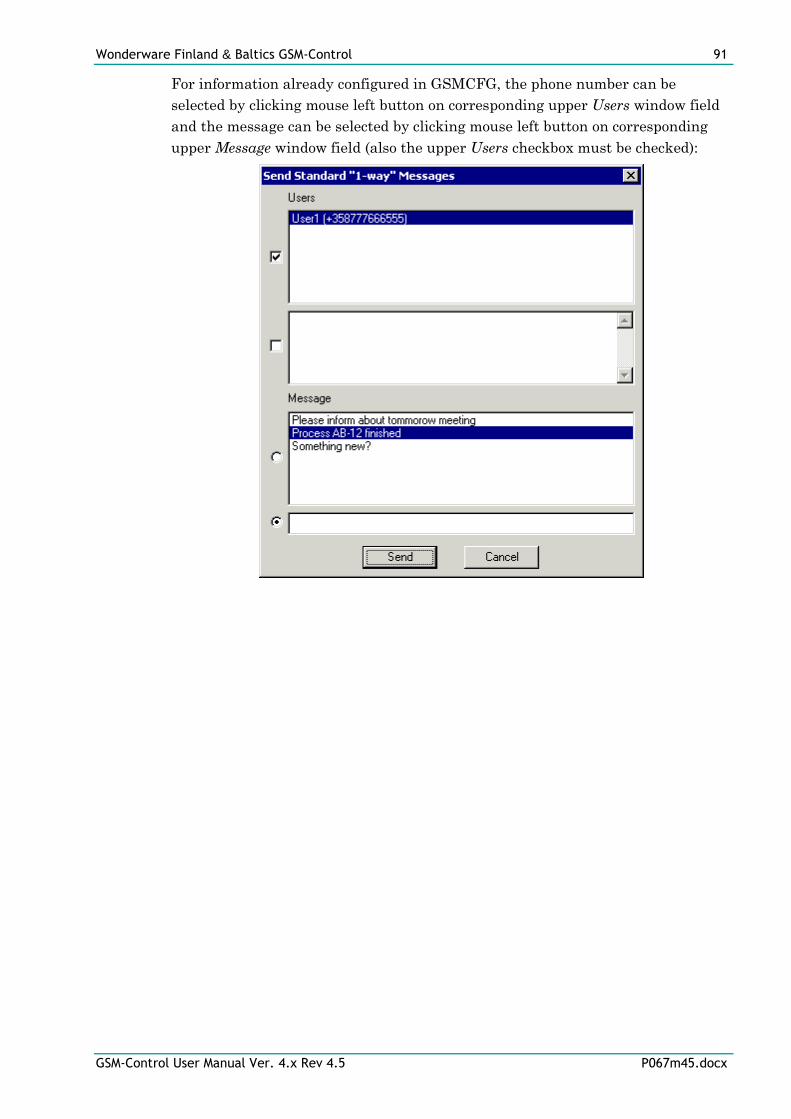
Wonderware Finland & Baltics GSM-Control 91
GSM-Control User Manual Ver. 4.x Rev 4.5 P067m45.docx
For information already configured in GSMCFG, the phone number can be
selected by clicking mouse left button on corresponding upper Users window field
and the message can be selected by clicking mouse left button on corresponding
upper Message window field (also the upper Users checkbox must be checked):
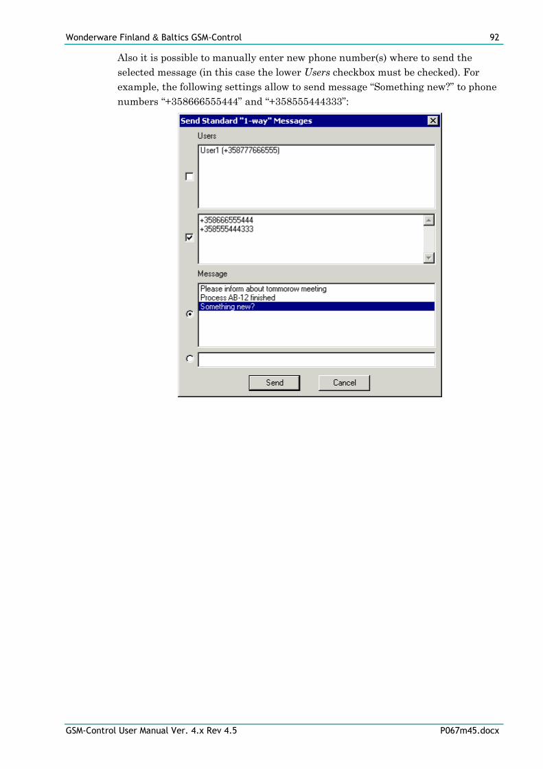
Wonderware Finland & Baltics GSM-Control 92
GSM-Control User Manual Ver. 4.x Rev 4.5 P067m45.docx
Also it is possible to manually enter new phone number(s) where to send the
selected message (in this case the lower Users checkbox must be checked). For
example, the following settings allow to send message “Something new?” to phone
numbers “+358666555444” and “+358555444333”:
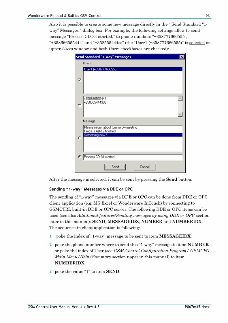
Wonderware Finland & Baltics GSM-Control 93
GSM-Control User Manual Ver. 4.x Rev 4.5 P067m45.docx
Also it is possible to create some new message directly in the " Send Standard “1-
way” Messages " dialog box. For example, the following settings allow to send
message “Process CD-34 started.” to phone numbers “+358777666555”,
“+358666555444” and “+358555444ss” (the “User1 (+358777666555)” is selected on
upper Users window and both Users checkboxes are checked):
After the message is selected, it can be sent by pressing the Send button.
Sending “1-way” Messages via DDE or OPC
The sending of “1-way” messages via DDE or OPC can be done from DDE or OPC
client application (e.g. MS Excel or Wonderware InTouch) by connecting to
GSMCTRL built-in DDE or OPC server. The following DDE or OPC items can be
used (see also Additional features/Sending messages by using DDE or OPC section
later in this manual): SEND, MESSAGEIDX, NUMBER and NUMBERIDX.
The sequence in client application is following:
1 poke the index of “1-way” message to be sent to item MESSAGEIDX;
2 poke the phone number where to send this “1-way” message to item NUMBER
or poke the index of User (see GSM-Control Configuration Program/ GSMCFG
Main Menu/Help/Summary section upper in this manual) to item
NUMBERIDX;
3 poke the value “1” to item SEND.
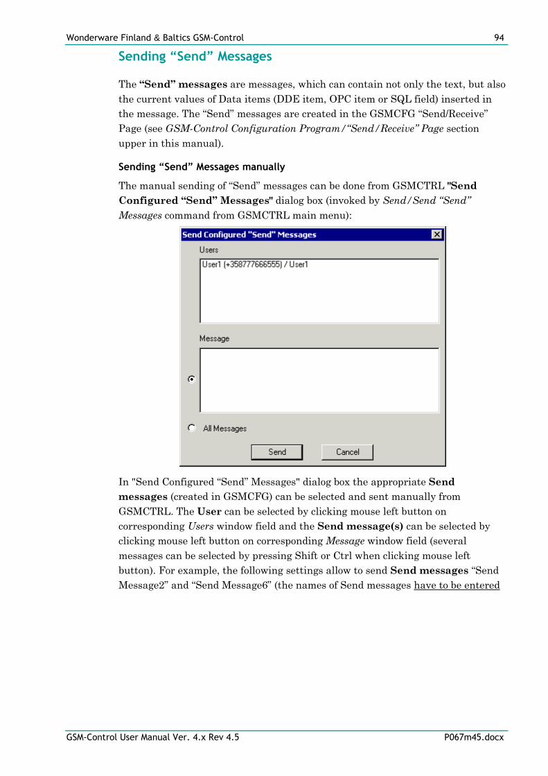
Wonderware Finland & Baltics GSM-Control 94
GSM-Control User Manual Ver. 4.x Rev 4.5 P067m45.docx
Sending “Send” Messages
The “Send” messages are messages, which can contain not only the text, but also
the current values of Data items (DDE item, OPC item or SQL field) inserted in
the message. The “Send” messages are created in the GSMCFG “Send/Receive”
Page (see GSM-Control Configuration Program/“Send/Receive” Page section
upper in this manual).
Sending “Send” Messages manually
The manual sending of “Send” messages can be done from GSMCTRL "Send
Configured “Send” Messages" dialog box (invoked by Send/Send “Send”
Messages command from GSMCTRL main menu):
In "Send Configured “Send” Messages" dialog box the appropriate Send
messages (created in GSMCFG) can be selected and sent manually from
GSMCTRL. The User can be selected by clicking mouse left button on
corresponding Users window field and the Send message(s) can be selected by
clicking mouse left button on corresponding Message window field (several
messages can be selected by pressing Shift or Ctrl when clicking mouse left
button). For example, the following settings allow to send Send messages “Send
Message2” and “Send Message6” (the names of Send messages have to be entered
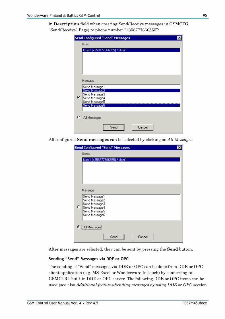
Wonderware Finland & Baltics GSM-Control 95
GSM-Control User Manual Ver. 4.x Rev 4.5 P067m45.docx
in Description field when creating Send/Receive messages in GSMCFG
“Send/Receive” Page) to phone number “+358777666555”:
All configured Send messages can be selected by clicking on All Messages:
After messages are selected, they can be sent by pressing the Send button.
Sending “Send” Messages via DDE or OPC
The sending of “Send” messages via DDE or OPC can be done from DDE or OPC
client application (e.g. MS Excel or Wonderware InTouch) by connecting to
GSMCTRL built-in DDE or OPC server. The following DDE or OPC items can be
used (see also Additional features/Sending messages by using DDE or OPC section
Wonderware Finland & Baltics GSM-Control 96
GSM-Control User Manual Ver. 4.x Rev 4.5 P067m45.docx
later in this manual): SEND_READS, MESSAGEIDX, NUMBER and
NUMBERIDX. The sequence in client application is following: 1) poke the index
(number) of “Send” message (see GSM-Control Configuration
Program/“Send/Receive” Page upper in this manual) to be sent to item
MESSAGEIDX; 2) poke the phone number where to send this “Send” message to
item NUMBER or poke the index of User (see GSM-Control Configuration
Program/ GSMCFG Main Menu/Help/Summary section upper in this manual) to
item NUMBERIDX; 3) poke the value “1” to item SEND_READS.
GSMCTRL.INI file
The GSM-Control Communication Program common settings are stored in the
GSMCTRL.INI file. This file is located in the same directory as GSMCTRL.EXE.
It is an ASCII file and can be altered manually if you wish with any text editor,
e.g. MS Windows Notepad (Do not use a program that formats text, such as MS
Word unless the file is saved as DOS text). The following is a typical content of the
GSMCTRL.INI file:
[GSMCtrl]
AdjInterval=2
SMTPServer=
ViewFlags=255
LogFile=1
Left=15
Top=98
Height=168
Width=518
Usually there is no need to modify the GSMCTRL.INI file manually, because most
of settings can be entered in GSMCTRL dialog boxes. Some special additional
entries are described below.
SendErrorRetries entry
The SendErrorRetries entry is used to specify the number of attempts to send
SMS Message before rejecting it. The default value (if there is no
SendErrorRetries entry in GSMCTRL.INI file) is 5. For example, by adding the
following GSMCTRL.INI entry
SendErrorRetries=3
the GSM-Control will try to send SMS Message 3 times before rejecting it.
Wonderware Finland & Baltics GSM-Control 97
GSM-Control User Manual Ver. 4.x Rev 4.5 P067m45.docx
NoAlarmIfAck entry
The GSMCTRL.INI file can contain a special setting (NoAlarmIfAck=1), which
can be used to disable the sending of Alarm Messages if alarm is already
acknowledged in the operator interface application (e.g. in InTouch). The
NoAlarmIfAck=1 can be used only if there is an Ack Item configured for Alarm
Message with which the alarm is associated. If GSMCTRL.INI file contains
NoAlarmIfAck=1 and Ack Item value is 1 (alarm is already acknowledged) then
corresponding Alarm Message will be not sent.
Entries for alternative (voice) call support in case SMS Service not available
The GSMCTRL.INI file can contain two special settings WAVFile= and
WAVSendRetries used to support the alternative (voice) call possibility in case
the GSM SM Service becomes inaccessible. This feature can be implemented in the
following way.
The WAVFile= entry is used to specify the name of sound file (prepared e.g. by
Microsoft Sound Recorder program), which will be sent to the current GSM phone
number by voice call after unsuccessful consecutive SendErrorRetries retries to
send SMS Message to this phone number. The WAVSendRetries entry (default
value is 3) can be used to specify the number of voice call retries before rejecting
the voice calls to this phone number (GSM-Control will wait 30 seconds for answer
on each voice call retry). To support the sending of sound files, the computer sound
card’s line-out must be connected to modem audio-in lines (e.g. to 4-pole Western
plug Microphone pins 1 and 4).
For example, by adding the following GSMCTRL.INI entries
WAVFile=C:\GSMCTRL\ALARM.WAV
WAVSendRetries =2
the GSM-Control will try to send (2 times) the sound file ALARM.WAV to current
GSM phone number (after unsuccessful consecutive SendErrorRetries retries to
send SMS Message to this phone number). By default (no WAVFile= entry in
GSMCTRL.INI file) the sending of alternative (voice) call is disabled.
AlarmCheckInterval
The AlarmCheckInterval entry can be added to GSMCTRL.INI file to specify the alarms scan rate (the update rate for DDE/OPC items configured as Alarm Items for Alarm messages). The default alarms scan rate (used if GSMCTRL.INI file does not contain this entry) is 2 seconds.
For example, the following entry can be used to specify the alarms scan rate equal
to 5 seconds:
AlarmCheckInterval=5
Wonderware Finland & Baltics GSM-Control 98
GSM-Control User Manual Ver. 4.x Rev 4.5 P067m45.docx
ModemRestartTimeout
The ModemRestartTimeout entry can be added to GSMCTRL.INI file to
disable or specify other value different from default value for the timeout when
GSM-modem is in “not registered in GSM-network” state continuously on and
after what GSM-modem will perform the GSM-modem reset and restart - whole
GSM-Control start-up sequence plus additionally for Siemens modems in the
beginning also the AT+CFUN=1,1 command will be executed.
The default ModemRestartTimeout (used if GSMCTRL.INI file does not
contain this entry) value is 300 seconds.
For example, the following entry can be used to specify the GSM-modem reset and
restart after being 10 minutes continuously in “not registered in GSM-network”
state:
ModemRestartTimeout =600
To disable the GSM-modem reset and restart, the following entry can be used:
ModemRestartTimeout =0
Note! The GSM-modem reset and restart will be performed also if GSM-Control
will detect modem power off/on (^SYSSTART received on COM port).
ModemRestartPeriod
The ModemRestartPeriod entry can be added to GSMCTRL.INI file to enable
the periodic automatic GSM-modem reset by executing the AT+CFUN=1,1
command. This setting is valid only for Siemens modems, the reset time interval is
in minutes.
The default ModemRestartPeriod (used if GSMCTRL.INI file does not contain
this entry) value is 0 – modem automatic reset disabled.
For example, the following entry can be used to specify the Siemens GSM-modem
automatic reset each 10 minutes:
ModemRestartPeriod =10
To disable the Siemens GSM-modem periodic automatic reset, the following entry
can be used:
ModemRestartPeriod =0
Special Character Sets
The processing of GSM-modem "AT+CSCS" command is included in GSMCTRL
start-up. The special character sets are processed in the following way.
The GSMCTRL at startup detects the character sets supported by GSM-modem
and selects “GSM” character set if available.
The character set can be specified in GSMCTRL.INI file by setting the line:
Wonderware Finland & Baltics GSM-Control 99
GSM-Control User Manual Ver. 4.x Rev 4.5 P067m45.docx
Charset=chset
Where chset is one of following: GSM, IRA, TTP, UCS2, PCCP850, PCCP852,
PCCP1250, PCCP1252, 8859-1, 8859-2, UTF-8, ERICSSON.
For example if PCCP1252 char set is used the GSMCTRL.INI file must contain
line:
Charset=PCCP1252
SMS Message Prefixes
User configured prefixes can be automatically added to SMS messages sent from
GSM-Control. To support prefixes, the following setting should be added to
GSMCTRL.INI file:
MsgPrefix=prefix
where prefix is a text to be added in the beginning of SMS message. For example,
the following setting:
MsgPrefix=*1#
will add characters *1# and one space before the SMS message text itself.
Mode settings
As default, GSM-Control sends short messages in PDU mode. The GSM-Control
detects the modes enabled in the GSM-moded during the GSMCTRL program
startup. By using PDU_MODE setting in GSMCTRL.INI file, you can force
usage of text or PDU SMS-message sending mode:
PDU_MODE=mode
Where mode can be 0 or 1. If mode is 0 then text mode will be used, if mode is 1
then PDU mode will be used.
Unicode settings
Some GSM-modems supports the Unicode character set. In Unicode the character
to be sent is precisely specified, but one character takes 2 times more space in the
SMS-message. For this reason Unicode messages are 2 times shorter than
messages if other character sets are used. If SMS-message to be sent by GSM
Control exceeds thje message length limit, then message is truncated before
sending and corresponding warning is logged to GSM-Control logger. To force the
Unicode usage, the following line should be placed in GSMCTRL.INI file:
UNICODE=mode
Where mode can be 0 or 1. The 0 specifies usage of character set specified by
Charset setting in GSMCTRL.INI file or the modem default character set if
Wonderware Finland & Baltics GSM-Control 100
GSM-Control User Manual Ver. 4.x Rev 4.5 P067m45.docx
Charset setting is not specified. The UNICODE=1 specifies the usage of Unicode
character set UCS2, if it is supported by the GSM-modem.
Debug settings
It is possible to trace all serial communication between PC and modem. This may
be useful in case of communication or GSM-Control program logic problems or if
using modem not tested with GSM-Control program. If some problems occur then
it is recommended to enable full logging of serial communication between PC and
modem. To enable the full logging, you can use the following settings in
GSMCTRL.INI file:
ShowSend=1
ShowReceive=1
To disable send and receive logging, you may delete these lines or specify value 0
instead of 1:
ShowSend=0
ShowReceive=0
User extension DLL
In some cases it is necessary to provide customized additional processing of
received or sent SMS-messages. For this purpose the customized dynamic link
library (dll) calls are implemented in GSM-Control to support the processing of
SMS send or receive events. To specify to use this dynamic link library, following
setting can be added in GSMCTRL.INI file:
EventDLL=path
where path is a full path to your own written dll file. If EventDLL setting is
specified,path exists and dll has functions with specific names, then for each event
one function of dll will be called with event code, phone number and message text
in function parameters. The customer is responsible to write this dll. The errors in
the customized dll can cause failure of GSMCTRL program, so the customized dll
should be very tested very accurate. In GSM-Control installation package there is
supplied example customized dynamic link library (USRDLL.ZIP, with source
included), which is written with Microsoft Visual C++ 6.0. The customized dll
must export two functions:
GSM_Version
GSM_Event
The GSM_Version function is called only once to determine the version of
customized dll interface. For current version of GSM-Control the GSM_Version
function must return hexadecimal value 00010000.
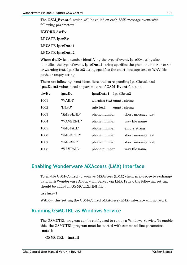
Wonderware Finland & Baltics GSM-Control 101
GSM-Control User Manual Ver. 4.x Rev 4.5 P067m45.docx
The GSM_Event function will be called on each SMS-message event with
following parameters:
DWORD dwEv
LPCSTR lpszEv
LPCSTR lpszData1
LPCSTR lpszData2
Where dwEv is a number identifying the type of event, lpszEv string also
identifies the type of event, lpszData1 string specifies the phone number or error
or warning text, lpszData2 string specifies the short message text or WAV file
path, or empty string.
There are following event identifiers and corresponding lpszData1 and
lpszData2 values used as parameters of GSM_Event function:
dwEv lpszEv lpszData1 lpszData2
1001 "WARN" warning text empty string
1002 "INFO" info text empty string
1003 "SMSSEND" phone number short message text
1004 "WAVSEND" phone number wav file name
1005 "SMSFAIL" phone number empty string
1006 "SMSDROP" phone number short message text
1007 "SMSREC" phone number short message text
1008 "WAVFAIL" phone number wav file name
Enabling Wonderware MXAccess (LMX) interface
To enable GSM-Control to work as MXAccess (LMX) client in purpose to exchange
data with Wonderware Application Server via LMX Proxy, the following setting
should be added in GSMCTRL.INI file:
uselmx=1
Without this setting the GSM-Control MXAccess (LMX) interface will not work.
Running GSMCTRL as Windows Service
The GSMCTRL program can be configured to run as a Windows Service. To enable
this, the GSMCTRL program must be started with command line parameter -
install:
GSMCTRL -install
Wonderware Finland & Baltics GSM-Control 102
GSM-Control User Manual Ver. 4.x Rev 4.5 P067m45.docx
After execution of this command, the Service with name GSMCTRLSRV is
installed with Startup type Automatic. Now rebooting the Windows will cause
the GSMCTRL to run automatically as Windows Service. It is expected the default
GSM-Control configuration file (DEFAULT.XML) will be used when starting
GSMCTRL as Windows Service, i.e. to use GSMCTRL running as Windows
Service with some other GSM-Control configuration file, it should be renamed to
DEFAULT.XML and copied to same directory where GSMCTRL.EXE is located.
The Service Startup configuration can be changed by MS Windows NT Control
Panel/Services configuration dialogs. The Allow Service to Interact with
Desktop checkbox in “Service” dialog box (invoked by pressing the “Startup”
button on “Services” dialog box when Service GSMCTRLSRV is selected) must be
checked to allow the user to interact with GSMCTRL program.
To disable the possibility for GSMCTRL program to run as a Windows Service, at
first the GSMCTRLSRV must be stopped by MS Windows NT Control
Panel/Services “Stop” button, and then GSMCTRL program must be started
manually with command line parameter -uninstall:
GSMCTRL -uninstall
After execution of this command, the Service with name GSMCTRLSRV will be
removed from system.
Note!
When starting the GSMCTRL program, the startup main events are logged to
GSMCTRL log file (see Menu Commands/Options/Logging section below). In
case the GSMCTRL program was started as Windows Service, the GSMCTRL log
file can contain the consecutive lines like following:
99/02/05 17:06:51.283/Can not open 'DEFAULT.XML'
99/02/05 17:06:51.283/Processing file 'd:\gsmctrl\DEFAULT.XML'
99/02/05 17:06:51.363/Processing file 'd:\gsmctrl\DEFAULT.XML' done.
The first line containing “Can not open 'DEFAULT.XML'” does not indicate some
error when opening file - it only informs that GSMCTRL program at first tried to
find the DEFAULT.XML file at location used by Services, and then next two lines
informs about successfully opened and processed DEFAULT.XML file at location
where GSMCTRL resides.
Running GSMCTRL as OPC Server
Usually GSMCTRL OPC support acts as OPC Client, but is it possible to use other
OPC Clients for data transmitting through GSMCTRL. In this case GSMCTRL
acts as OPC Server. To install GSM-Control OPC version to run as OPC Server,
the GSMCTRL OPC version must be started with command line parameter
"/RegServer":
Wonderware Finland & Baltics GSM-Control 103
GSM-Control User Manual Ver. 4.x Rev 4.5 P067m45.docx
GSMCTRL /RegServer
After above operation GSMCTRL OPC Server will appear in the OPC Servers list
and becomes accessible for OPC Clients.
Note!
GSMCTRL OPC Server registration is included in the GSM-Control installation
package delivered by Wonderware Finland & Baltics. In this case above operation
is not necessary.
For GSMCTRL OPC Server mode deactivation the GSMCTRL has to be started
with the following command line parameter:
GSMCTRL /UnregServer
After above operation GSMCTRL OPC Server will disappear from the OPC
Servers list accessible for OPC Clients.
Configuring DCOM
After GSMCTRL OPC Server installation the System Administrator must
configure DCOM by DCOM configuration program - by Dcomcnfg.exe (or
Dcomcnfg32.exe for Win9x) system tool. This utility is located in the Windows
system directory - e.g. in \WinNT\system32\ or \Win9x\system\. After starting
Dcomcnfg.exe, select GSMCTRL OPC Server on Applications page and click on
Properties - the “GSMCTRL OPC Server Properties” window will appear. All
further configuration is to be done from there.
Configuring DCOM to access GSM-Control as a local OPC Server
To access GSM Control as a local OPC server:
Authentication level can be any of:
(None)
Call
Connect
Default
Packet
Packet Integrity
Packet Privacy
Location
“Run application on this computer” must be checked.
Security/access permissions - default access permissions can be used in case
using GSM-Control as local OPC server. If it is necessary to access GSM-Control
Wonderware Finland & Baltics GSM-Control 104
GSM-Control User Manual Ver. 4.x Rev 4.5 P067m45.docx
OPC Server from local OPC Clients configured as services, then Allow Access
permission must be configured for SYSTEM and for all users, which need access
to the GSM-Control OPC server.
Security/launch permissions - Allow Launch must be specified for each user,
which launches OPC Client on local machine. Typically specify Allow Launch for
“Users” group. If is necessary to access GSM-Control OPC Server from local OPC
Clients configured as services then Allow Launch permission must be
configured for SYSTEM also.
Security/configuration permissions
Administrators - Full Control
CREATOR OWNER - Full Control
SYSTEM - Full Control
Full Control for all users, which have permission to register GSM-Control as
OPC server.
For users, which have permission to read data from OPC server the sufficient
permission is Read.
Note - OPC server registration and unregistration is silent. No error messages are
displayed if operation is unavailable due to permission restrictions.
Identify
Identify has to be The launching user. In case of using GSM Control as local
OPC server, the Identify can be also The interactive user, but this setting will
not work if user is not logged on and OPC Clients which are running as services
will not be able to connect to the GSM-Control OPC server while user is not logged
on computer.
Also This user can be selected. In this case GSM-Control OPC Server will be
invisible on the screen and GSM-Control user interface will be inaccessible. If user
is different as user logged on then GSM-Control OPC Server cannot be terminated
by Task Manager. The user specified in this setting can be any user which have
access to hardware and software resources used by GSM-Control. This user can be
without permission to launch or configure OPC Server specified in the Security
page of DCOM configuration program.
Configuring DCOM to access GSM-Control as a remote OPC Server
To access GSM-Control as a remote OPC server (form remote computer) and to
browse available OPC Servers, at first you have to configure DCOM settings for
OPCEnum.exe. OPCEnum.exe, opccomn_ps.dll and OPCProxy.dll must be
installed and registered on both - server and client computers and GSM-Control
Wonderware Finland & Baltics GSM-Control 105
GSM-Control User Manual Ver. 4.x Rev 4.5 P067m45.docx
OPC Server must be installed and registered at computer where it will run. For
some OPC clients it may be necessary to register OPC Server on client computer.
OPCEnum is used to browse OPC servers on local or remote computer, the
DCOM settings for OPCEnum.exe are following:
Location
“Run application on this computer” - must be checked on both computers.
Security/Access permissions can be default.
Security/launch permissions
Launch permission must be set for each user, which can be able to configure OPC
items on OPC Server computer. On the client computer OPCEnum launch
permissions can be default, but some OPC clients may handle this situation
incorrectly, therefore it is better to assign launch permission for users working on
remote OPC client computer.
Security/configuration permissions
SYSTEM must have at least Read permission on OPC Server computer. On OPC
Client computers at least Read permission must be set for users working with
OPC clients.
Administrators must have Full Control permission on both computers, otherwise
nobody can be able to configure or unregister OPCEnum.
Identify
On GSM-Control OPC Server computer the Identify must be set to The
interactive User. On remote OPC Client computer it can be The interactive
user or The launching user.
DCOM Settings for GSM-Control as remote OPC Server:
Location - “Run application on this computer” must be checked.
Security/access permissions can be default. If GSM-Control OPC Server is
running as service, then Allow Access permission should be set for NETWORK
and remote OPC client computers.
Security/launch permissions must be set to NETWORK and for users working
on remote client computers.
Security/configuration permissions - Read must be set for NETWORK and
for users working on remote OPC client computers.
Identify - The interactive user must be selected.
Most frequent errors when configuring DCOM
The following table contains most frequent errors when configuring DCOM.
Wonderware Finland & Baltics GSM-Control 106
GSM-Control User Manual Ver. 4.x Rev 4.5 P067m45.docx
Error message Possible reason
DCOM not installed DCOM has not been installed
Server execution failed 1) OPC Server can not be started
2) Identity for OPC server not properly configured
3) OPC Server is not located on a local hard disk
4) OPC Server path in registry is too long or uses LFN (Long
File Names)
5) DCOMCNFG Location is not set to Run on this
computer.
Class not registered OPC Server has not been registered
RPC server is unavailable 1) Remote Procedure Call service is not running on the
OPC Server computer
2) Invalid computer name for remote OPC Server
3) Make sure TCP/IP is installed properly
Interface not supported 1) Permission not granted to OPC Client
2) Guest account disabled
Access is denied 1) DCOM security not configured properly
2) OPC Server application not located on local hard disk
3) SYSTEM account in DCOMCNFG must have Access,
Launch and Configure privileges
Error 80070776 Network error - TCP/IP has not been configured properly
Catastrophic failure 1) Trying to access an object before it is created
2) Unhandled exception is occurs on the OPC Server
Not enough storage SYSTEM account in DCOMCNFG must have Access,
Launch and Configure privileges
Sending messages by using DDE or OPC
The direct sending (one direction communication) of SMS messages from GSM-
Control Communication Program can be performed using DDE or OPC. In this
case the GSMCTRL acts as a DDE or OPC Server allowing other Windows
application programs to send SMS messages via the GSM-Control. This GSM-
Control feature can be used by any Microsoft Windows program that is capable to
act as a DDE or OPC Client.
DDE items
The DDE protocol identifies an element of data by using a three-part address,
including: Application, Topic and Item.
Application refers to the name of the Windows program (server) with which
the client wants to exchange the data. In the case of GSMCTRL the application
portion of the DDE address is "GSMCTRL".
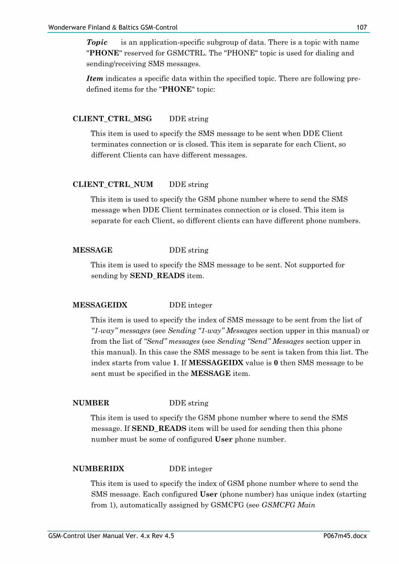
Wonderware Finland & Baltics GSM-Control 107
GSM-Control User Manual Ver. 4.x Rev 4.5 P067m45.docx
Topic is an application-specific subgroup of data. There is a topic with name
"PHONE" reserved for GSMCTRL. The "PHONE" topic is used for dialing and
sending/receiving SMS messages.
Item indicates a specific data within the specified topic. There are following pre-
defined items for the "PHONE" topic:
CLIENT_CTRL_MSG DDE string
This item is used to specify the SMS message to be sent when DDE Client
terminates connection or is closed. This item is separate for each Client, so
different Clients can have different messages.
CLIENT_CTRL_NUM DDE string
This item is used to specify the GSM phone number where to send the SMS
message when DDE Client terminates connection or is closed. This item is
separate for each Client, so different clients can have different phone numbers.
MESSAGE DDE string
This item is used to specify the SMS message to be sent. Not supported for
sending by SEND_READS item.
MESSAGEIDX DDE integer
This item is used to specify the index of SMS message to be sent from the list of
“1-way” messages (see Sending “1-way” Messages section upper in this manual) or
from the list of “Send” messages (see Sending “Send” Messages section upper in
this manual). In this case the SMS message to be sent is taken from this list. The
index starts from value 1. If MESSAGEIDX value is 0 then SMS message to be
sent must be specified in the MESSAGE item.
NUMBER DDE string
This item is used to specify the GSM phone number where to send the SMS
message. If SEND_READS item will be used for sending then this phone
number must be some of configured User phone number.
NUMBERIDX DDE integer
This item is used to specify the index of GSM phone number where to send the
SMS message. Each configured User (phone number) has unique index (starting
from 1), automatically assigned by GSMCFG (see GSMCFG Main
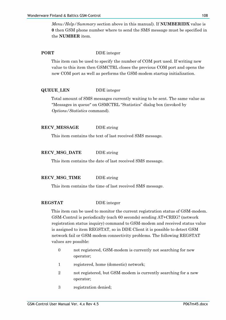
Wonderware Finland & Baltics GSM-Control 108
GSM-Control User Manual Ver. 4.x Rev 4.5 P067m45.docx
Menu/Help/Summary section above in this manual). If NUMBERIDX value is
0 then GSM phone number where to send the SMS message must be specified in
the NUMBER item.
PORT DDE integer
This item can be used to specify the number of COM port used. If writing new
value to this item then GSMCTRL closes the previous COM port and opens the
new COM port as well as performs the GSM-modem startup initialization.
QUEUE_LEN DDE integer
Total amount of SMS messages currently waiting to be sent. The same value as
"Messages in queue" on GSMCTRL “Statistics” dialog box (invoked by
Options/Statistics command).
RECV_MESSAGE DDE string
This item contains the text of last received SMS message.
RECV_MSG_DATE DDE string
This item contains the date of last received SMS message.
RECV_MSG_TIME DDE string
This item contains the time of last received SMS message.
REGSTAT DDE integer
This item can be used to monitor the current registration status of GSM-modem.
GSM-Control is periodically (each 60 seconds) sending AT+CREG? (network
registration status inquiry) command to GSM-modem and received status value
is assigned to item REGSTAT, so in DDE Client it is possible to detect GSM
network fail or GSM-modem connectivity problems. The following REGSTAT
values are possible:
0 not registered, GSM-modem is currently not searching for new
operator;
1 registered, home (domestic) network;
2 not registered, but GSM-modem is currently searching for a new
operator;
3 registration denied;
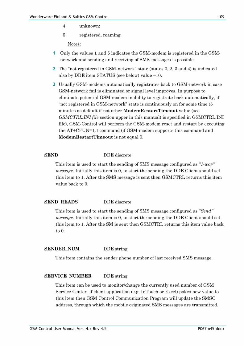
Wonderware Finland & Baltics GSM-Control 109
GSM-Control User Manual Ver. 4.x Rev 4.5 P067m45.docx
4 unknown;
5 registered, roaming.
Notes:
1 Only the values 1 and 5 indicates the GSM-modem is registered in the GSM-
network and sending and receiving of SMS-messages is possible.
2 The “not registered in GSM-network” state (states 0, 2, 3 and 4) is indicated
also by DDE item STATUS (see below) value –10.
3 Usually GSM-modems automatically registrates back to GSM-network in case
GSM-network fail is eliminated or signal level improves. In purpose to
eliminate potential GSM-modem inability to registrate back automatically, if
“not registered in GSM-network” state is continuously on for some time (5
minutes as default if not other ModemRestartTimeout value (see
GSMCTRL.INI file section upper in this manual) is specified in GSMCTRL.INI
file), GSM-Control will perform the GSM-modem reset and restart by executing
the AT+CFUN=1,1 command (if GSM-modem supports this command and
ModemRestartTimeout is not equal 0.
SEND DDE discrete
This item is used to start the sending of SMS message configured as “1-way”
message. Initially this item is 0, to start the sending the DDE Client should set
this item to 1. After the SMS message is sent then GSMCTRL returns this item
value back to 0.
SEND_READS DDE discrete
This item is used to start the sending of SMS message configured as “Send”
message. Initially this item is 0, to start the sending the DDE Client should set
this item to 1. After the SM is sent then GSMCTRL returns this item value back
to 0.
SENDER_NUM DDE string
This item contains the sender phone number of last received SMS message.
SERVICE_NUMBER DDE string
This item can be used to monitor/change the currently used number of GSM
Service Center. If client application (e.g. InTouch or Excel) pokes new value to
this item then GSM Control Communication Program will update the SMSC
address, through which the mobile originated SMS messages are transmitted.
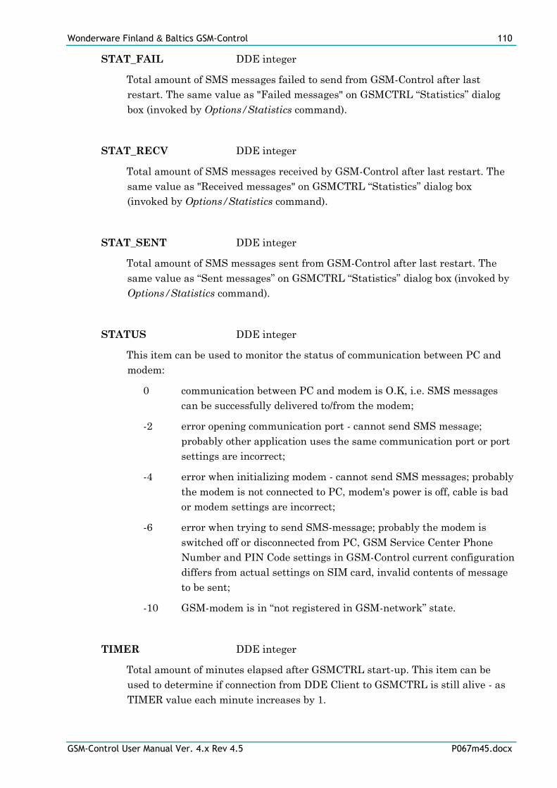
Wonderware Finland & Baltics GSM-Control 110
GSM-Control User Manual Ver. 4.x Rev 4.5 P067m45.docx
STAT_FAIL DDE integer
Total amount of SMS messages failed to send from GSM-Control after last
restart. The same value as "Failed messages" on GSMCTRL “Statistics” dialog
box (invoked by Options/Statistics command).
STAT_RECV DDE integer
Total amount of SMS messages received by GSM-Control after last restart. The
same value as "Received messages" on GSMCTRL “Statistics” dialog box
(invoked by Options/Statistics command).
STAT_SENT DDE integer
Total amount of SMS messages sent from GSM-Control after last restart. The
same value as “Sent messages” on GSMCTRL “Statistics” dialog box (invoked by
Options/Statistics command).
STATUS DDE integer
This item can be used to monitor the status of communication between PC and
modem:
0 communication between PC and modem is O.K, i.e. SMS messages
can be successfully delivered to/from the modem;
-2 error opening communication port - cannot send SMS message;
probably other application uses the same communication port or port
settings are incorrect;
-4 error when initializing modem - cannot send SMS messages; probably
the modem is not connected to PC, modem's power is off, cable is bad
or modem settings are incorrect;
-6 error when trying to send SMS-message; probably the modem is
switched off or disconnected from PC, GSM Service Center Phone
Number and PIN Code settings in GSM-Control current configuration
differs from actual settings on SIM card, invalid contents of message
to be sent;
-10 GSM-modem is in “not registered in GSM-network” state.
TIMER DDE integer
Total amount of minutes elapsed after GSMCTRL start-up. This item can be
used to determine if connection from DDE Client to GSMCTRL is still alive - as
TIMER value each minute increases by 1.
Wonderware Finland & Baltics GSM-Control 111
GSM-Control User Manual Ver. 4.x Rev 4.5 P067m45.docx
Sending SMS message by using DDE
All necessary configuration should be done before sending SMS message.
To perform the sending of SMS messages, the DDE Client (for example, InTouch
or Excel) has to perform the following steps (see also Examples how to use GSM-
Control / GSM-Control with MS Excel (DDE) / Sending “1-way messages” and
Sending “Send” Messages sections upper in this manual):
1 Establish DDE link with the GSMCTRL using Application "GSMCTRL" and
Topic "PHONE".
2 Directly specify the number of GSM phone where to send the SMS message in
the DDE item NUMBER or specify the index of GSM phone number in the
DDE item NUMBERIDX.
3 Poke the text of SMS message to be send directly into DDE item MESSAGE or
specify the index of message (from the list of “1-way” messages or from the list
of “Send” messages) in the DDE item MESSAGEIDX.
4 Poke "1" into DDE item SEND or SEND_READS.
5 Wait and monitor the value of DDE item SEND or SEND_READS while it
becomes "0". When it happens then sending is completed.
6 Monitor the value of DDE item STATUS while sending the first SMS message.
If the value of STATUS all the time is 0 then the communication between PC
and modem is O.K. and SMS messages can be successfully delivered.
Sending SMS message when DDE client terminates the connection
It is possible to send SMS message when Client terminates the DDE connection, is
closed or crashes. To do so, the DDE Client must write (poke) SMS message text
into the DDE item CLIENT_CTRL_MSG and GSM phone number into the DDE
item CLIENT_CTRL_NUM. These items are separate for each DDE Client, so
different Clients can have different messages and phone numbers.
Special "DUMMY" Topic
The special topic "DUMMY" can be useful when GSMCTRL is used with some
DDE Client (e.g. Wonderware InTouch) and DDE Server, which uses the serial
port. Other programs should not use the serial port used for sending of SMS
message, but serial DDE Servers are doing that when DDE Client has established
the DDE link with them. This link must be closed before sending the SMS
message and this can be done by redirecting this link to other topic (e.g. by
"SetDdeAppTopic" script command in InTouch). After SMS message is sent, the
link with serial DDE Server can be reestablished (e.g. again by "SetDdeAppTopic"
script command in InTouch). The "DUMMY" topic can be useful in this case.
Wonderware Finland & Baltics GSM-Control 112
GSM-Control User Manual Ver. 4.x Rev 4.5 P067m45.docx
The "DUMMY" item accepts DDE requests for any DDE item, but does not send
data as well as does not accept new data values.
OPC Items
The GSMCTRL as an OPC Server contains the data address space described
below. This address space includes the following pre-defined items for the
"PHONE" data group, the values of these items are in the VARIANT format.
MESSAGE native type - VT_BSTR
This item is used to specify the SMS message to be sent. Not supported for
sending by SEND_READS item.
MESSAGEIDX native type - VT_I4
This item is used to specify the index of SMS message to be sent from the list of
“1-way” messages (see Sending “1-way” Messages section upper in this manual) or
from the list of “Send” messages (see Sending “Send” Messages section upper in
this manual). In this case the SMS message to be sent is taken from this list. The
index starts from value 1. If MESSAGEIDX value is 0 then SMS message to be
sent must be specified in the MESSAGE item.
NUMBER native type - VT_BSTR
This item is used to specify the GSM phone number where to send the SMS
message. If SEND_READS item will be used for sending then this phone
number must be some of configured User phone number.
NUMBERIDX native type - VT_I4
This item is used to specify the index of GSM phone number where to send the
SMS message. Each configured User (phone number) has unique index (starting
from 1), automatically assigned by GSMCFG (see GSMCFG Main
Menu/Help/Summary section above in this manual). If NUMBERIDX value is
0 then GSM phone number where to send the SMS message must be specified in
the NUMBER item.
PORT native type - VT_I4
This item can be used to specify the number of COM port used. If writing new
value to this item then GSMCTRL closes the previous COM port and opens the
new COM port as well as performs the GSM-modem startup initialization.
Wonderware Finland & Baltics GSM-Control 113
GSM-Control User Manual Ver. 4.x Rev 4.5 P067m45.docx
QUEUE_LEN native type - VT_I4
Total amount of SMS messages currently waiting to be sent. The same value as
"Messages in queue" on GSMCTRL “Statistics” dialog box (invoked by
Options/Statistics command).
RECV_MESSAGE native type - VT_BSTR
This item contains the text of last received SMS message.
REGSTAT native type - VT_I4
This item can be used to monitor the current registration status of GSM-modem.
GSM-Control is periodically (each 60 seconds) sending AT+CREG? (network
registration status inquiry) command to GSM-modem and received status value
is assigned to item REGSTAT, so in OPC Client it is possible to detect GSM
network fail or GSM-modem connectivity problems. The following REGSTAT
values are possible:
0 not registered, GSM-modem is currently not searching for new
operator;
1 registered, home (domestic) network;
2 not registered, but GSM-modem is currently searching for a new
operator;
3 registration denied;
4 unknown;
5 registered, roaming.
Notes:
1 Only the values 1 and 5 indicates the GSM-modem is registered in the GSM-
network and sending and receiving of SMS-messages is possible.
2 The “not registered in GSM-network” state (states 0, 2, 3 and 4) is indicated
also by OPC item STATUS (see below) value –10.
3 Usually GSM-modems automatically registrates back to GSM-network in case
GSM-network fail is eliminated or signal level improves. In purpose to
eliminate potential GSM-modem inability to registrate back automatically, if
“not registered in GSM-network” state is continuously on for some time (5
minutes as default if not other ModemRestartTimeout value (see
GSMCTRL.INI file section upper in this manual) is specified in GSMCTRL.INI
file), GSM-Control will perform the GSM-modem reset and restart by executing
Wonderware Finland & Baltics GSM-Control 114
GSM-Control User Manual Ver. 4.x Rev 4.5 P067m45.docx
the AT+CFUN=1,1 command (if GSM-modem supports this command and
ModemRestartTimeout is not equal 0.
RECV_MSG_DATE native type - VT_BSTR
This item contains the date of last received SMS message.
RECV_MSG_TIME native type - VT_BSTR
This item contains the time of last received SMS message.
SEND native type - VT_BOOL
This item is used to start the sending of SMS message configured as “1-way”
message. Initially this item is 0, to start the sending the OPC Client should set
this item to 1. After the SMS message is sent then GSMCTRL returns this item
value back to 0.
SEND_READS native type - VT_BOOL
This item is used to start the sending of SMS message configured as “Send”
message. Initially this item is 0, to start the sending the OPC Client should set
this item to 1. After the SM is sent then GSMCTRL returns this item value back
to 0.
SENDER_NUM native type - VT_BSTR
This item contains the sender phone number of last received SMS message.
SERVICE_NUMBER native type - VT_BSTR
This item can be used to monitor/change the currently used number of GSM
Service Center. If OPC Client pokes new value to this item then GSM Control
Communication Program will update the SMSC address, through which the
mobile originated SMS messages are transmitted.
STAT_FAIL native type - VT_I4
Total amount of SMS messages failed to send from GSM-Control after last
restart. The same value as "Failed messages" on GSMCTRL “Statistics” dialog
box (invoked by Options/Statistics command).
STAT_RECV native type - VT_I4
Wonderware Finland & Baltics GSM-Control 115
GSM-Control User Manual Ver. 4.x Rev 4.5 P067m45.docx
Total amount of SMS messages received by GSM-Control after last restart. The
same value as "Received messages" on GSMCTRL “Statistics” dialog box
(invoked by Options/Statistics command).
STAT_SENT native type - VT_I4
Total amount of SMS messages sent from GSM-Control after last restart. The
same value as “Sent messages” on GSMCTRL “Statistics” dialog box (invoked by
Options/Statistics command).
STATUS native type - VT_I4
This item can be used to monitor the status of communication between PC and
modem:
0 communication between PC and modem is O.K, i.e. SMS messages
are successfully delivered to the modem;
-2 error opening communication port - cannot send SMS message;
probably other application uses the same communication port or port
settings are incorrect;
-4 error when initializing modem - cannot send SMS messages; probably
the modem is not connected to PC, modem's power is off, cable is bad
or modem settings are incorrect;
-6 error when trying to send SMS-message; probably the modem is
switched off or disconnected from PC, GSM Service Center Phone
Number and PIN Code settings in GSM-Control current configuration
differs from actual settings on SIM card, invalid contents of message
to be sent;
-10 GSM-modem is in “not registered in GSM-network” state.
TIMER native type - VT_I4
Total amount of minutes elapsed after GSMCTRL start-up. This item can be
used to determine if connection from OPC Client to GSMCTRL OPC Server is
still alive - as TIMER value each minute increases by 1.
Sending SMS message by using OPC
All necessary configuration should be done before sending SMS message.
To send a SMS message, the OPC Client must perform the following steps (in
further explanation the FactorySoft OPC Client program is used as an example of
OPC Client):
Wonderware Finland & Baltics GSM-Control 116
GSM-Control User Manual Ver. 4.x Rev 4.5 P067m45.docx
1 Establish the OPC connection with GSMCTRL OPC Server by using OPC
Client menu item OPC/Connect and select the "GSMCTRL OPC Server".
2 By using the OPC Client menu item OPC/Add Item: add and directly specify in
the OPC item PHONE.NUMBER the number of GSM phone where to send the
SMS message or specify the index of GSM phone number in the OPC item
PHONE.NUMBERIDX.
3 Put the SMS message to be send directly into OPC item PHONE.MESSAGE or
specify the index of message ((from the list of “1-way” messages or from the list
of “Send” messages)) in the OPC item PHONE.MESSAGEIDX.
4 Put "1" into OPC item PHONE.SEND or PHONE.SEND_READS.
5 Wait and monitor the value of OPC item PHONE.SEND or
PHONE.SEND_READS while it becomes "0". When it happens then sending
is completed.
6 Monitor the value of OPC item PHONE.STATUS while sending the first SMS
message. If the value of PHONE.STATUS all the time is 0 then the
communication between PC and modem is O.K. and SMS messages can be
successfully delivered.
Sending and Receiving messages by e-mail
Using GSM-Control as a mailserver
GSM-Control has built-in support for sending and (or) receiving e-mails, i.e. GSM-
Control can work as a “pure” mailserver - in this case GSM-Control may run even
without GSM-modem connected - GSM-modem can be replaced by e-mail
connection. To configure User as e-mail sender or receiver, simply replace User
phone number by e-mail address (see GSMCFG Main Window/”Users” Page
section upper in this manual).
The e-mail address of GSM-Control is automatically created the following way:
where "hostname" is the name of computer where GSM-Control is running and
"domain" is the domain name where this computer belongs to. For example, to
send e-mail to GSM-Control running on computer MyPC and belonging to domain
mycompany.cc, the e-mail address to be used is [email protected].
To enable the possibility to send e-mails from GSM-Control, the Host name of
the SMTP (Simple Mail Transfer Protocol) Server used to process e-mails must be
configured in GSM-Control Communication Program (see
“Options/Communications” in GSM-Control Communication Program/GSMCTRL
Menu Commands section upper in this manual).
To enable the possibility to receive e-mails in GSM-Control, your computer name
has to be included in the list of local hosts on your local DNS server (like usually it
Wonderware Finland & Baltics GSM-Control 117
GSM-Control User Manual Ver. 4.x Rev 4.5 P067m45.docx
is) and on your mailserver the forwarding of incoming e-mails to GSM-Control e-
mail address must be enabled. For example, if MS Exchange Server is used,
GSM-Control e-mail address is [email protected] and IP address of
computer where GSM-Control is running is 111.222.333.444 then following
actions are necessary:
- on MS Exchange Server create the custom recipient with address
- on local DNS controller there must be record with host name and IP address:
MyPC/111.222.333.444;
- if there is no record MyPC.mycompany.cc in DNS records at ISP (Internet
Service Provider) then this record must be added (as 111.222.333.444
MyPC.mycompany.cc) to the hosts file (located as
%sysroot%\system32\drivers\etc\hosts).
Note!
If GSM-Control is used as a “pure” mailserver without GSM-modem connected then
GSMCTRL log file is consecutively filled with messages “ATI timeout, no response
from modem”. The support of “pure” mailserver is not a GSM-Control basic feature,
so such a logging can be considered as dispensable.
Sending/receiving SMS Messages by e-mails from/to GSM-Control
GSM-Control supports the possibility to send SMS Messages by e-mails from
GSM-Control to GSM network and to receive SMS Messages as e-mails from GSM
network. To configure User as e-mail sender or receiver, simply replace User
phone number by e-mail address (see GSMCFG Main Window/”Users” Page
section upper in this manual). This e-mail address usually contains the mobile
user GSM phone number. If your GSM provider does not support possibility to
send/receive SMS Messages by e-mail, then you cannot use this GSM-Control
additional feature.
The implementation of sending/receiving SMS Messages by e-mail varies for
different mobile operators and countries. The following is some general example
how sending/receiving SMS Messages could work:
- to send SMS Message from mobile phone to GSM-Control by e-mail: on your
mobile phone or device select “Write Message”, start message text with the GSM-
Control e-mail address (receiver of message, e.g. [email protected]),
then enter some special separator (e.g. space or #) and then proceed with the
message itself; then send it to your GSM provider phone number reserved for
sending SMS Messages from mobile phone to e-mail (e.g. 9912); the SMS
Message now will be delivered to GSM-Control by e-mail;
- to send SMS Message by e-mail from GSM-Control to GSM mobile phone or
device: at first an “account” has to be opened at your GSM provider for receiver’s
phone number and then you can send e-mail containing the message text to
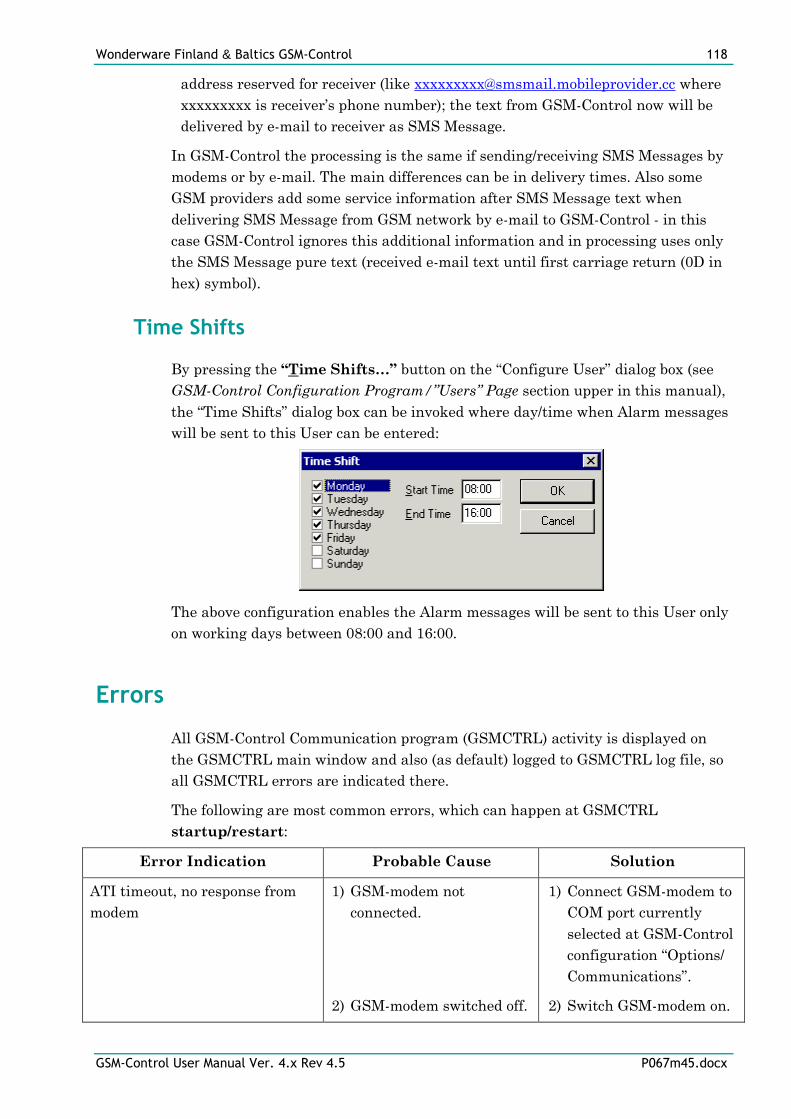
Wonderware Finland & Baltics GSM-Control 118
GSM-Control User Manual Ver. 4.x Rev 4.5 P067m45.docx
address reserved for receiver (like [email protected] where
xxxxxxxxx is receiver’s phone number); the text from GSM-Control now will be
delivered by e-mail to receiver as SMS Message.
In GSM-Control the processing is the same if sending/receiving SMS Messages by
modems or by e-mail. The main differences can be in delivery times. Also some
GSM providers add some service information after SMS Message text when
delivering SMS Message from GSM network by e-mail to GSM-Control - in this
case GSM-Control ignores this additional information and in processing uses only
the SMS Message pure text (received e-mail text until first carriage return (0D in
hex) symbol).
Time Shifts
By pressing the “Time Shifts…” button on the “Configure User” dialog box (see
GSM-Control Configuration Program/”Users” Page section upper in this manual),
the “Time Shifts” dialog box can be invoked where day/time when Alarm messages
will be sent to this User can be entered:
The above configuration enables the Alarm messages will be sent to this User only
on working days between 08:00 and 16:00.
Errors
All GSM-Control Communication program (GSMCTRL) activity is displayed on
the GSMCTRL main window and also (as default) logged to GSMCTRL log file, so
all GSMCTRL errors are indicated there.
The following are most common errors, which can happen at GSMCTRL
startup/restart:
Error Indication Probable Cause Solution
ATI timeout, no response from
modem
1) GSM-modem not
connected.
2) GSM-modem switched off.
1) Connect GSM-modem to
COM port currently
selected at GSM-Control
configuration “Options/
Communications”.
2) Switch GSM-modem on.
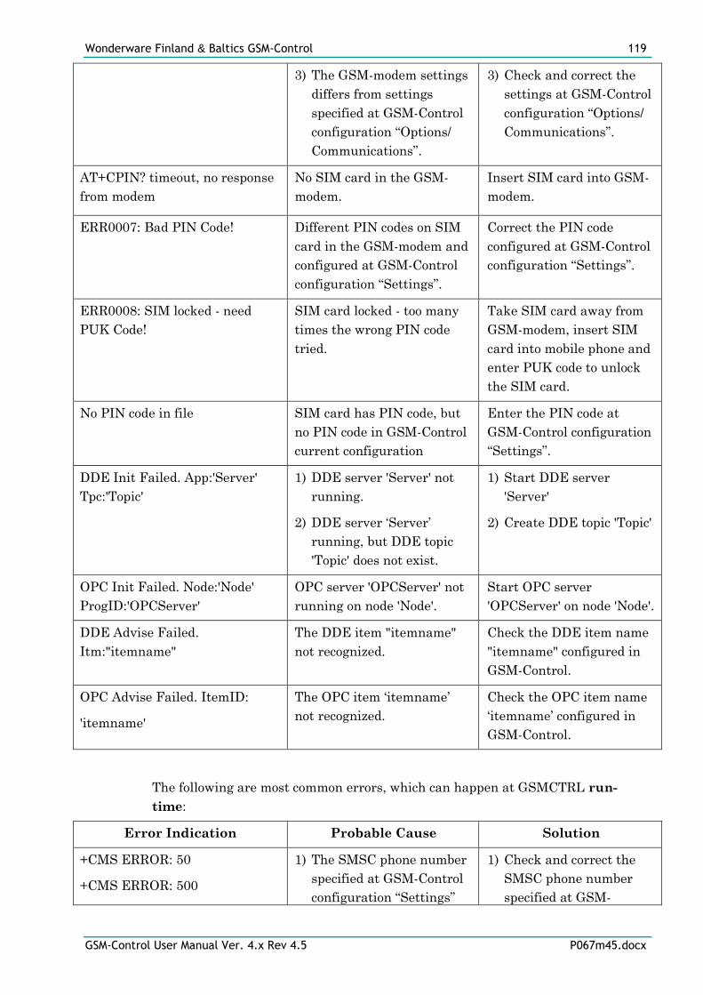
Wonderware Finland & Baltics GSM-Control 119
GSM-Control User Manual Ver. 4.x Rev 4.5 P067m45.docx
3) The GSM-modem settings
differs from settings
specified at GSM-Control
configuration “Options/
Communications”.
3) Check and correct the
settings at GSM-Control
configuration “Options/
Communications”.
AT+CPIN? timeout, no response
from modem
No SIM card in the GSM-
modem.
Insert SIM card into GSM-
modem.
ERR0007: Bad PIN Code! Different PIN codes on SIM
card in the GSM-modem and
configured at GSM-Control
configuration “Settings”.
Correct the PIN code
configured at GSM-Control
configuration “Settings”.
ERR0008: SIM locked - need
PUK Code!
SIM card locked - too many
times the wrong PIN code
tried.
Take SIM card away from
GSM-modem, insert SIM
card into mobile phone and
enter PUK code to unlock
the SIM card.
No PIN code in file SIM card has PIN code, but
no PIN code in GSM-Control
current configuration
Enter the PIN code at
GSM-Control configuration
“Settings”.
DDE Init Failed. App:'Server'
Tpc:'Topic'
1) DDE server 'Server' not
running.
2) DDE server ‘Server’
running, but DDE topic
'Topic' does not exist.
1) Start DDE server
'Server'
2) Create DDE topic 'Topic'
OPC Init Failed. Node:'Node'
ProgID:'OPCServer'
OPC server 'OPCServer' not
running on node 'Node'.
Start OPC server
'OPCServer' on node 'Node'.
DDE Advise Failed.
Itm:"itemname"
The DDE item "itemname"
not recognized.
Check the DDE item name
"itemname" configured in
GSM-Control.
OPC Advise Failed. ItemID:
'itemname'
The OPC item ‘itemname’
not recognized.
Check the OPC item name
‘itemname’ configured in
GSM-Control.
The following are most common errors, which can happen at GSMCTRL run-
time:
Error Indication Probable Cause Solution
+CMS ERROR: 50
+CMS ERROR: 500
1) The SMSC phone number
specified at GSM-Control
configuration “Settings”
1) Check and correct the
SMSC phone number
specified at GSM-
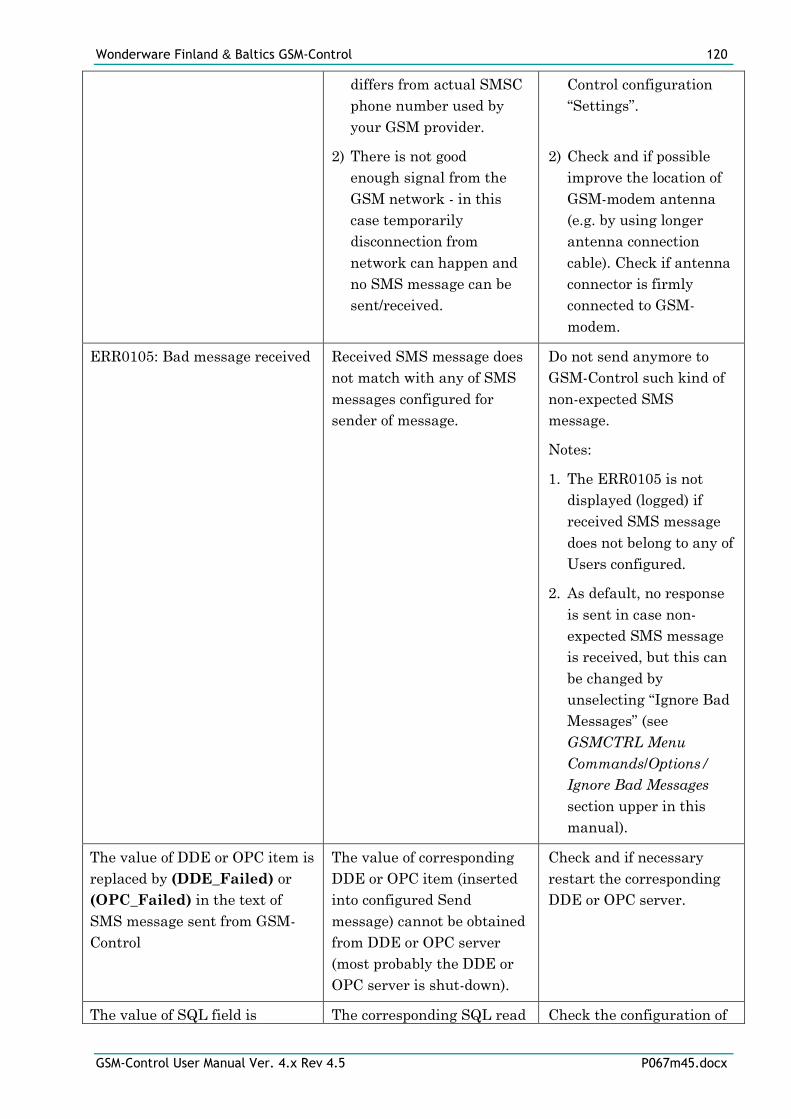
Wonderware Finland & Baltics GSM-Control 120
GSM-Control User Manual Ver. 4.x Rev 4.5 P067m45.docx
differs from actual SMSC
phone number used by
your GSM provider.
2) There is not good
enough signal from the
GSM network - in this
case temporarily
disconnection from
network can happen and
no SMS message can be
sent/received.
Control configuration
“Settings”.
2) Check and if possible
improve the location of
GSM-modem antenna
(e.g. by using longer
antenna connection
cable). Check if antenna
connector is firmly
connected to GSM-
modem.
ERR0105: Bad message received Received SMS message does
not match with any of SMS
messages configured for
sender of message.
Do not send anymore to
GSM-Control such kind of
non-expected SMS
message.
Notes:
1. The ERR0105 is not
displayed (logged) if
received SMS message
does not belong to any of
Users configured.
2. As default, no response
is sent in case non-
expected SMS message
is received, but this can
be changed by
unselecting “Ignore Bad
Messages” (see
GSMCTRL Menu
Commands/Options/
Ignore Bad Messages
section upper in this
manual).
The value of DDE or OPC item is
replaced by (DDE_Failed) or
(OPC_Failed) in the text of
SMS message sent from GSM-
Control
The value of corresponding
DDE or OPC item (inserted
into configured Send
message) cannot be obtained
from DDE or OPC server
(most probably the DDE or
OPC server is shut-down).
Check and if necessary
restart the corresponding
DDE or OPC server.
The value of SQL field is The corresponding SQL read Check the configuration of
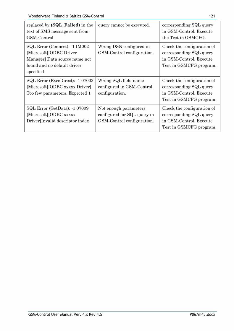
Wonderware Finland & Baltics GSM-Control 121
GSM-Control User Manual Ver. 4.x Rev 4.5 P067m45.docx
replaced by (SQL_Failed) in the
text of SMS message sent from
GSM-Control
query cannot be executed. corresponding SQL query
in GSM-Control. Execute
the Test in GSMCFG.
SQL Error (Connect): -1 IM002
[Microsoft][ODBC Driver
Manager] Data source name not
found and no default driver
specified
Wrong DSN configured in
GSM-Control configuration.
Check the configuration of
corresponding SQL query
in GSM-Control. Execute
Test in GSMCFG program.
SQL Error (ExecDirect): -1 07002
[Microsoft][ODBC xxxxx Driver]
Too few parameters. Expected 1
Wrong SQL field name
configured in GSM-Control
configuration.
Check the configuration of
corresponding SQL query
in GSM-Control. Execute
Test in GSMCFG program.
SQL Error (GetData): -1 07009
[Microsoft][ODBC xxxxx
Driver]Invalid descriptor index
Not enough parameters
configured for SQL query in
GSM-Control configuration.
Check the configuration of
corresponding SQL query
in GSM-Control. Execute
Test in GSMCFG program.
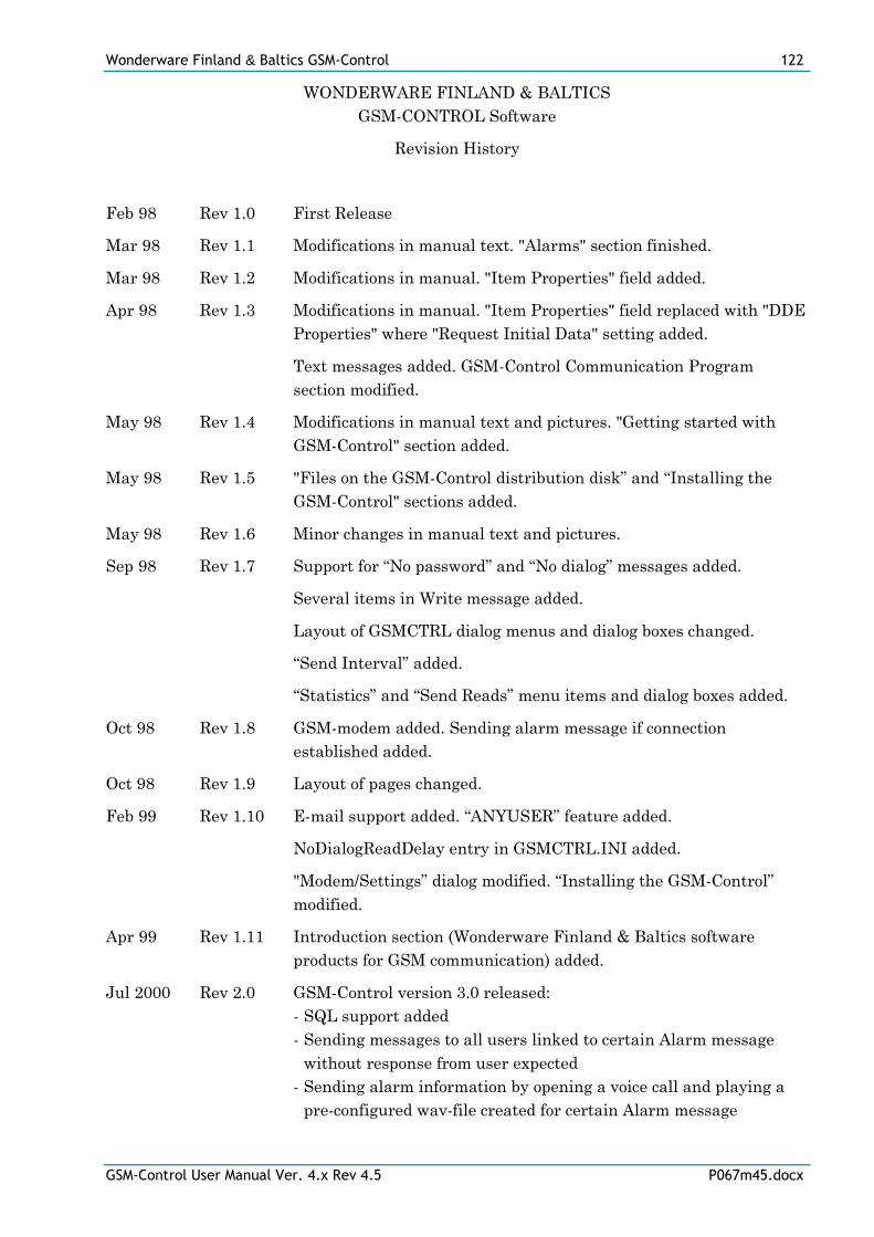
Wonderware Finland & Baltics GSM-Control 122
GSM-Control User Manual Ver. 4.x Rev 4.5 P067m45.docx
WONDERWARE FINLAND & BALTICS
GSM-CONTROL Software
Revision History
Feb 98 Rev 1.0 First Release
Mar 98 Rev 1.1 Modifications in manual text. "Alarms" section finished.
Mar 98 Rev 1.2 Modifications in manual. "Item Properties" field added.
Apr 98 Rev 1.3 Modifications in manual. "Item Properties" field replaced with "DDE
Properties" where "Request Initial Data" setting added.
Text messages added. GSM-Control Communication Program
section modified.
May 98 Rev 1.4 Modifications in manual text and pictures. "Getting started with
GSM-Control" section added.
May 98 Rev 1.5 "Files on the GSM-Control distribution disk” and “Installing the
GSM-Control" sections added.
May 98 Rev 1.6 Minor changes in manual text and pictures.
Sep 98 Rev 1.7 Support for “No password” and “No dialog” messages added.
Several items in Write message added.
Layout of GSMCTRL dialog menus and dialog boxes changed.
“Send Interval” added.
“Statistics” and “Send Reads” menu items and dialog boxes added.
Oct 98 Rev 1.8 GSM-modem added. Sending alarm message if connection
established added.
Oct 98 Rev 1.9 Layout of pages changed.
Feb 99 Rev 1.10 E-mail support added. “ANYUSER” feature added.
NoDialogReadDelay entry in GSMCTRL.INI added.
"Modem/Settings” dialog modified. “Installing the GSM-Control”
modified.
Apr 99 Rev 1.11 Introduction section (Wonderware Finland & Baltics software
products for GSM communication) added.
Jul 2000 Rev 2.0 GSM-Control version 3.0 released:
- SQL support added
- Sending messages to all users linked to certain Alarm message
without response from user expected
- Sending alarm information by opening a voice call and playing a
pre-configured wav-file created for certain Alarm message
Wonderware Finland & Baltics GSM-Control 123
GSM-Control User Manual Ver. 4.x Rev 4.5 P067m45.docx
- Support up to 500 Alarm messages added
- Special character sets support added
- Support for special prefixes in SMS Messages added
- Ignore Bad Messages feature added
- Sonera Content Gateway support added
Dec 2000 Rev 2.1 GSM-Control OPC version added to this manual. Writing to SQL
database support added.
Feb 2001 Rev 2.2 Configuring SQL Data in GSM-Control Configuration Tool section
modified.
Mar 2002 Rev 3.0 New release 4.0 of GSM-Control.
Apr 2002 Rev 3.1 “Simulate” dialog box changed. “Sending and Receiving SMS
messages by e-mail” section changed.
Jul 2003 Rev 3.2 “Installing the GSM-Control”, “Getting started with GSM-modem
connected”, “”Users” Page”, “GSMCTRL.INI file”, “DDE items” and
“OPC items” sections modified. “Advanced User” section removed.
Wrong “Running GSMCTRL as Windows NT Service” section
removed.
Jan 2004 Rev 3.3 Modifications made in correspondence with GSM-Control version
4.15:
“Options/Terminal”, “Options/Close Port Temporary”,
“Options/Edit GSMCTRL.INI” sections added in “GSMCTRL Menu
Commands/Options” chapter. “ModemRestartTimeout” section
modified and “ModemRestartPeriod” section added in
“GSMCTRL.INI file” chapter. New item TIMER added in “DDE
items” and “OPC items” sections.
Sep 2004 Rev 3.4 “Send To All” feature added “Send/Receive Settings” dialog box
Aug 2005 Rev 3.5 Wonderware Lmx Proxy interface added.
Mar 2007 Rev 3.6 “GSMCTRL.INI file” chapter “ModemRestartPeriod” description
modified.
Sep 2007 Rev 4.0 “Introduction, Wonderware Finland & Baltics Wireless M2M
Concept” section modified.
Jun 2008 Rev 4.1 “Introduction, Wonderware Finland & Baltics Wireless M2M
Concept” section removed. Lmx Proxy interface changed to
MXAccess.
Jul 2008 Rev 4.2 “Modem and accessories” section added.
Jul 2010 Rev 4.3 Working with software license key description added. In “GSM-
Control with Wonderware Application Server” section the
description of “uselmx=1” setting added.
Wonderware Finland & Baltics GSM-Control 124
GSM-Control User Manual Ver. 4.x Rev 4.5 P067m45.docx
Aug 2012 Rev 4.4 “Installing the GSM-Control” section modified, the “Licensing by
using HASP HL key”sub-section added.
Jan 2013 Rev 4.5 “Installing the GSM-Control” section modified.