GSM BASED ENERGY METER BILLING WITH LOAD CONTROL Submitted By.
29
GSM BASED ENERGY METER BILLING WITH LOAD CONTROL Submitted By
-
Upload
emerald-parker -
Category
Documents
-
view
227 -
download
4
Transcript of GSM BASED ENERGY METER BILLING WITH LOAD CONTROL Submitted By.

GSM BASED ENERGY METER BILLING WITH LOAD CONTROL
Submitted By

Introduction
The main objective of the project is to develop a wireless energy meter and load control.The microcontroller takes the reading from the energy meter and displays the reading on the LCD.The reading of the energy meter is also sent to the cell phone of the user by a message through GSM modem.which also receives commands from any cell phone to control the electrical loads

ContentsIntroductionBlock diagramHardware requirements Power supplyGSMOpto isolatorSCROpto-isolator Schematic diagramWorking of the projectAdvantages ApplicationsConclusion
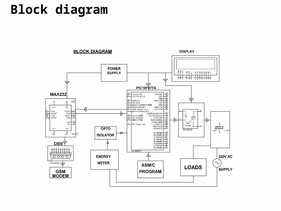
Block diagram

Hardware requirementsTRANSFORMER (230 – 12 V AC)VOLTAGE REGULATOR (LM 7805)RECTIFIER FILTER PIC MICROCONTROLLER (PIC16F877A) GSM COMMUNICATION GSM MODEMSCROPTO-ISOLATORLED LCD DISPLAY MAX 232 DB9 CONNECTOR ENERGY METER OPTO COUPLER 1N4007 RESISTOR CAPACITOR

Hardware Components description 1. 230 V AC 50 Hz 12V step down transformer
2. Using In4007 as Bridge rectifier
3. Capacitors Filter(470µf) 4. 5v Regulator

7. OPTO-ISOLATOR 6. GSM MODEM
8. Max 2320
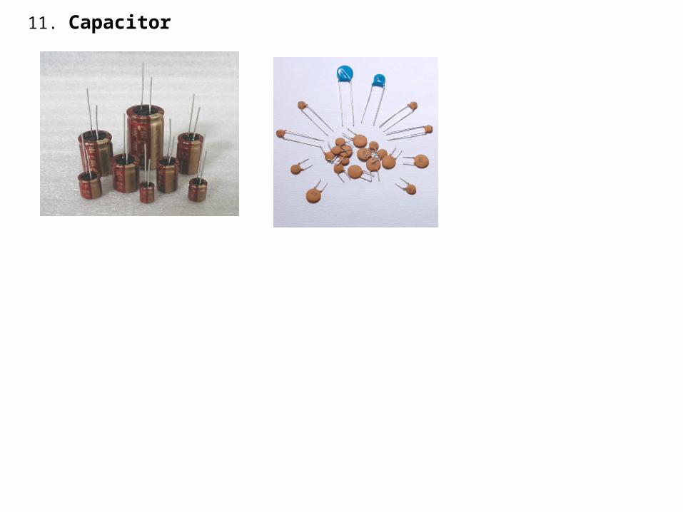
11. Capacitor

Power supply

Description of power supply
The circuit uses standard power supply comprising of a step-down transformer from 230v to 12v and 4 diodes forming a Bridge Rectifier that delivers pulsating dc which is then filtered by an electrolytic capacitor of about 470microf to 100microF. The filtered dc being un regulated IC LM7805 is used to get 5v constant at its pin no 3 irrespective of input dc varying from 9v to 14v.The regulated 5volts dc is further filtered by a small electrolytic capacitor of 10 micro f for any noise so generated by the circuit. One LED is connected of this 5v point in series with a resistor of 330ohms to the ground i.e. negative voltage to indicate 5v power supply availability.

PIC (PIC16F877A)• High-Performance RISC CPU:• Only 35 single-word instructions.• All single-cycle instructions except for program
branches, which are two cycle.• Operating speed: DC – 20 MHz clock input DC
– 200 ns instruction cycle• Up to 8K x 14 words of Flash Program Memory,
Up to 368 x 8 bytes of Data Memory (RAM), Up to 256 x 8 bytes of EEPROM Data Memory.
• Pin out compatible to other 28-pin or 40/44-pin, PIC16CXXX and PIC16FXXX microcontrollers.

Special Microcontroller Features:
• 100,000 erase/write cycle Enhanced Flash program memory typical.
• 1,000,000 erase/write cycle Data EEPROM memory typical.• Data EEPROM Retention > 40 years.• Self-reprogrammable under software control.• In-Circuit Serial Programming™ (ICSP™) via two pins.• Single-supply 5V In-Circuit Serial Programming.• Watchdog Timer (WDT) with its own on-chip RC oscillator
for reliable operation.• Programmable code protection.• Power saving Sleep mode.• Selectable oscillator options.• In-Circuit Debug (ICD) via two pins.

Peripheral Features:• Timer0: 8-bit timer/counter with 8-bit prescaler.• Timer1: 16-bit timer/counter with prescaler, can be
incremented during Sleep via external crystal/clock.• Timer2: 8-bit timer/counter with 8-bit period register,
prescaler and postscaler.• Two Capture, Compare, PWM modules• - Capture is 16-bit, max. resolution is 12.5 ns• - Compare is 16-bit, max. resolution is 200 ns• - PWM max resolution is 10-bit• Synchronous Serial Port (SSP) with SPI™ (Master mode) and
I2C™ (Master/Slave).• Universal Synchronous Asynchronous Receiver Transmitter
(USART/SCI) with 9-bit address detection.• Parallel Slave Port (PSP) – 8 bits wide with external RD, WR
and CS controls (40/44-pin only).• Brown-out detection circuitry for Brown-out Reset (BOR).

PIN DIAGRAM OF PIC16F877
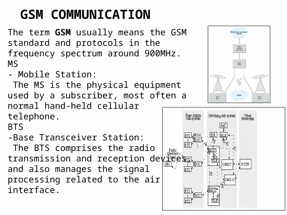
GSM COMMUNICATIONThe term GSM usually means the GSM standard and protocols in the frequency spectrum around 900MHz.MS- Mobile Station: The MS is the physical equipment used by a subscriber, most often a normal hand-held cellular telephone.BTS-Base Transceiver Station: The BTS comprises the radio transmission and reception devices, and also manages the signal processing related to the air interface.
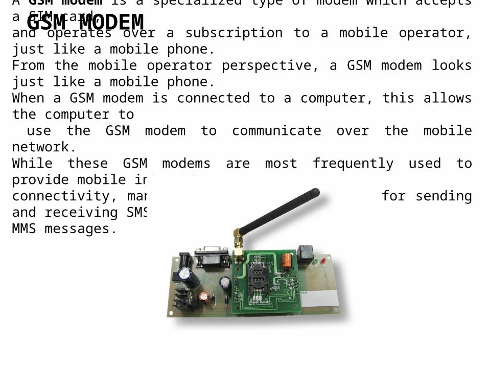
GSM MODEMA GSM modem is a specialized type of modem which accepts a SIM card, and operates over a subscription to a mobile operator, just like a mobile phone. From the mobile operator perspective, a GSM modem looks just like a mobile phone.When a GSM modem is connected to a computer, this allows the computer to use the GSM modem to communicate over the mobile network. While these GSM modems are most frequently used to provide mobile internet connectivity, many of them can also be used for sending and receiving SMS and MMS messages.

TRIAC
TRIAC, from Triode for Alternating Current, is a generalized trade name for an electronic component which can conduct current in either direction when it is triggered (turned on), and is formally called a bidirectional triode thyristor or bilateral triode thyristor.
OPTO-ISOLATOR
Opto-coupler MOC3061/63 an LED SCR type combination.
Opto coupler is a 6 pin IC.
Additionally while using this IC with microcontroller and one
LED can be connected in series with IC LED to indicate when high
is given from micro controller such that we can know that current is
flowing in internal LED of the opto-IC.
When logic high is given current flows through LED from pin 1
to 2 .So in this process LED light falls on SCR causing 6 & 4 to
close only at the zero cross of the supply voltage.

During each half cycle current flows through scr gate,
external series resistor and through opto-scr for the main
thyristor / triac to trigger for the load at the beginning of the
supply cycle always to operate.
Contd….

Opto-isolator Opto coupler is a 6 pin IC. It is a combination of 1 LED and a transistorPin 6 of transistor is not generally used and when light falls on the Base-Emitter junction then it switches and pin5 goes to zero.
An energy or electric meter is a device that measures the amount of electrical energy consumed by a residence, business, or an electrically-powered device.Electric meters are typically calibrated in billing units, the most common one being the kilowatt hour. Periodic readings of electric meters establish billing cycles and energy used during a cycle.
ENERGY METER

MAX 232The MAX232 is an integrated circuit that converts signals from an RS-232serial port to signals suitable for use in TTL compatible digital logic circuits.
The MAX232 is a dual driver/receiver and typically converts the RX, TX, CTS and RTS signals .
When a MAX232 IC receives a TTL level to convert, it changes a TTL Logic 0 to between +3 and +15V, and changes TTL Logic 1 to between -3 to -15V, and vice versa for converting from RS232 to TTL.

DB9 CONNECTOR
The DB9 (originally DE-9) connector is an analog 9-pin plug of the D-Sub miniature connector family (D-Sub or Sub-D).
LIQUID CRYSTAL DISPLAY (LCD)
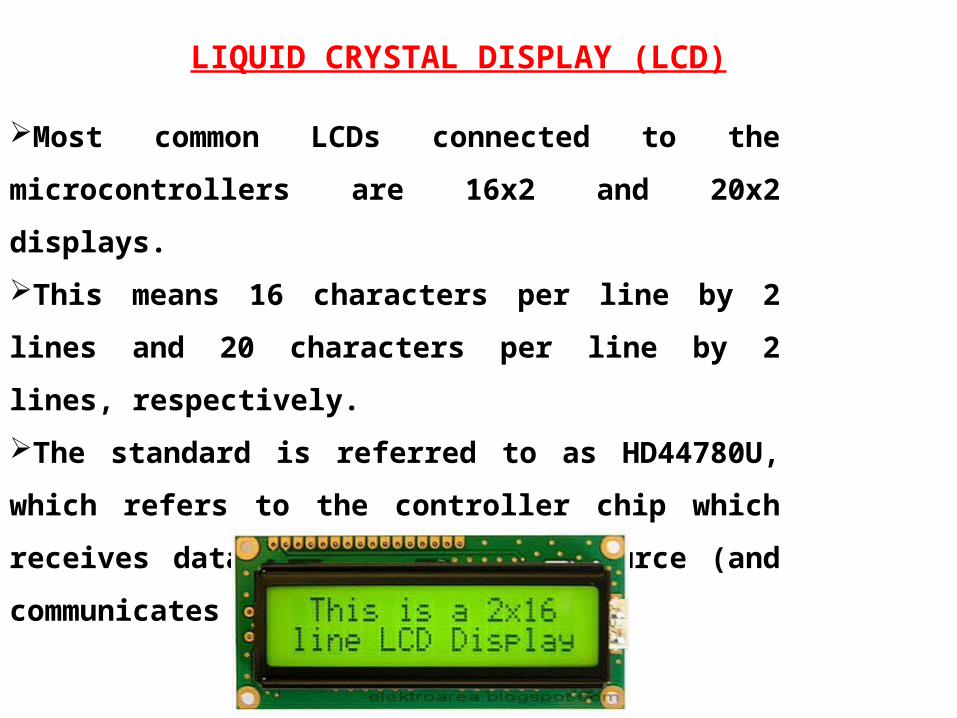
Most common LCDs connected to the microcontrollers are
16x2 and 20x2 displays.
This means 16 characters per line by 2 lines and 20
characters per line by 2 lines, respectively.
The standard is referred to as HD44780U, which refers to
the controller chip which receives data from an external
source (and communicates directly with the LCD.

LCD BACKGROUND
If an 8-bit data bus is used the LCD will require 11 data lines
(3 control lines plus the 8 lines for the data bus)
The three control lines are referred to as EN, RS, and RW
EN=Enable (used to tell the LCD that you are sending it data)
RS=Register Select (When RS is low (0), data is treated as a command)
(When RS is High(1), data being sent is text data )
R/W=Read/Write (When RW is low (0), the data written to the LCD)
(When RW is low (0), the data reading to the LCD)

Advantages
• A convenient and efficient method to avoid the problem of electricity department sending employees for taking meter reading every month.
• Reduces number of employees in electricity department.
• Automation of home/industrial loads using SMS from any remote place.
• Less time consuming

Disadvantages
• If there is some network problem, then the SMS may not be conveyed to the electricity department or there may be problem in operating the loads.

QUERIES ?

THANKYOU