GSM Based Electronics Notice Board - · PDF file · 2016-11-04GSM Based Electronics...
5
Volume 4, Issue 3 (2016) 483-487 ISSN 2347 - 3258 International Journal of Advance Research and Innovation 483 IJARI GSM Based Electronics –Notice Board Prerana Chauhan*, Shikhar Agarwal, Hem Kumar Singh, Ashish Saini* Department of Electronic Engineering, Moradabad Institute of Technology, Moradabad, (UP) India Abstract In this technical paper explains how a reliable and an authentic wireless communication could be easily developed between a mobile phone and microcontroller using GSM (Global System for Mobile Communication) MODEM (Modulator-Demodulator). This technical paper explains GSM based e-notice board which can be widely used for multitude of applications including educational sector, traffic control, banks, public advertisements, stoke exchanges etc. Moreover we can also learn as well as modify some of the common applications of GSM MODEM as per the requirements and needs of the user. Here we will learn the hardware behind the picture. In addition to this I will tell you how to upgrade the software resulting low NRE (Non-Recurring Engineering) cost as well as low time-to-market. This technical paper plays a vital role in the state-of-the-art scenario where market window is relentlessly shrinking and really need pocket-friendly and authentic products. 1. Introduction In this project it is possible to display as SMS on moving led pattern. For this project we use GSM modem as a main component. We send the SMS via mobile phone to particular GSM modem. Data from the modem is connected to the microcontroller VIA SERIAL PORT. Data is get into the microcontroller and store in the memory and then after into the microcontroller. This project is to be divided into two parts. One is GSM modem connectivity and second is moving display board. The main aim of this project will be to design a SMS driven automatic display board which can replace the currently used programmable electronic display. It is proposed to design receiver cum display board which can be programmed from an authorized mobile phone. The message to be displayed is sent through a SMS from an authorized transmitter. The microcontroller receives the SMS, validates the sending Mobile Identification Number (MIN) and displays the desired information. The GSM modem receives the SMS. The AT commands are serially transferred to the modem through Rx-Tx connection. The microcontroller validates the SMS and then displays the message in the LED display board. 2. Main Function of GSM Based E-Notice Board Sending message from any of the remote area to the distant located e-notice board using GSM mobile. For sending the text message from remote area we need to interface the mobile phone with GSM Modem. For developing some of GSM based applications we need to have some commons peripherals including GSM MODEM, SIM, microcontroller, LED, power supply and also some connecting wires. Moreover GSM based applications could *Corresponding Author, E-mail address: [email protected]; [email protected] All rights reserved: http://www.ijari.org be easily developed and enhanced due to easily accessibility of components in local markets at very pocket friendly prices. 2.1 Block Diagram of GSM-Based E-Notice Board Here you can see the simple block diagram of GSM- based e-Notice board. Essential components for assembling GSM based applications including: 1. GSM MODEM 2. Microcontroller 3. SIM 4. Power Supply or Power Adapter 5. Transformer 6. Bridge Rectifier 7. LED Let’s start discussion one by one. Fig 1: Block Diagram of GSM Based E- Notice Board 2.2GSM Modem: A GSM modem is a wireless modem that works with a GSM wireless network. It operates at either the 900MHz or 1800MHz frequency band. It supports voice calls and data transfer speeds of up to 9.6kbits/s, together with the transmission of SMS (Short Message Service). The GSM Modem comes with a serial interface which the Article Info Article history: Received 25 January 2016 Received in revised form 20 February 2016 Accepted 28 February 2016 Available online 15 June 2016 Keywords Transformer, Diode(IN4007),GSM , Voltage regulator 7805,Microcontroller,LED, Transistor, MAX 232,IC 74154, IC 74138.
Transcript of GSM Based Electronics Notice Board - · PDF file · 2016-11-04GSM Based Electronics...

Volume 4, Issue 3 (2016) 483-487 ISSN 2347 - 3258 International Journal of Advance Research and Innovation
483 IJARI
GSM Based Electronics –Notice Board
Prerana Chauhan*, Shikhar Agarwal, Hem Kumar Singh, Ashish Saini*
Department of Electronic Engineering, Moradabad Institute of Technology, Moradabad, (UP) India
Abstract
In this technical paper explains how a reliable and an authentic wireless
communication could be easily developed between a mobile phone and
microcontroller using GSM (Global System for Mobile Communication)
MODEM (Modulator-Demodulator). This technical paper explains GSM based
e-notice board which can be widely used for multitude of applications including
educational sector, traffic control, banks, public advertisements, stoke exchanges
etc. Moreover we can also learn as well as modify some of the common
applications of GSM MODEM as per the requirements and needs of the user.
Here we will learn the hardware behind the picture. In addition to this I will tell
you how to upgrade the software resulting low NRE (Non-Recurring
Engineering) cost as well as low time-to-market. This technical paper plays a
vital role in the state-of-the-art scenario where market window is relentlessly
shrinking and really need pocket-friendly and authentic products.
1. Introduction
In this project it is possible to display as SMS on moving
led pattern. For this project we use GSM modem as a main
component. We send the SMS via mobile phone to
particular GSM modem. Data from the modem is connected
to the microcontroller VIA SERIAL PORT. Data is get into
the microcontroller and store in the memory and then after
into the microcontroller. This project is to be divided into
two parts. One is GSM modem connectivity and second is
moving display board.
The main aim of this project will be to design a SMS driven
automatic display board which can replace the currently
used programmable electronic display. It is proposed to
design receiver cum display board which can be
programmed from an authorized mobile phone. The
message to be displayed is sent through a SMS from an
authorized transmitter. The microcontroller receives the
SMS, validates the sending Mobile Identification Number
(MIN) and displays the desired information. The GSM
modem receives the SMS. The AT commands are serially
transferred to the modem through Rx-Tx connection. The
microcontroller validates the SMS and then displays the
message in the LED display board.
2. Main Function of GSM Based E-Notice Board
Sending message from any of the remote area to
the distant located e-notice board using GSM
mobile.
For sending the text message from remote area we
need to interface the mobile phone with GSM
Modem.
For developing some of GSM based applications
we need to have some commons peripherals
including GSM MODEM, SIM, microcontroller,
LED, power supply and also some connecting
wires. Moreover GSM based applications could
*Corresponding Author,
E-mail address: [email protected];
All rights reserved: http://www.ijari.org
be easily developed and enhanced due to easily accessibility
of components in local markets at very pocket friendly
prices.
2.1 Block Diagram of GSM-Based E-Notice Board Here you can see the simple block diagram of GSM- based
e-Notice board.
Essential components for assembling GSM based
applications including:
1. GSM MODEM
2. Microcontroller
3. SIM
4. Power Supply or Power Adapter
5. Transformer
6. Bridge Rectifier
7. LED
Let’s start discussion one by one.
Fig 1: Block Diagram of GSM Based E- Notice Board
2.2GSM Modem: A GSM modem is a wireless modem that
works with a GSM wireless network. It operates at either
the 900MHz or 1800MHz frequency band. It supports voice
calls and data transfer speeds of up to 9.6kbits/s, together
with the transmission of SMS (Short Message Service). The
GSM Modem comes with a serial interface which the
Article Info
Article history:
Received 25 January 2016
Received in revised form
20 February 2016
Accepted 28 February 2016
Available online 15 June 2016
Keywords
Transformer, Diode(IN4007),GSM ,
Voltage regulator
7805,Microcontroller,LED,
Transistor, MAX 232,IC 74154, IC
74138.

Volume 4, Issue 3 (2016) 483-487 ISSN 2347 - 3258 International Journal of Advance Research and Innovation
484 IJARI
modem can be controlled using AT command interface.
Fig 2: GSM Modem
2.3 SIM: Subscriber Identity Module is a clip-on small card
consisting of user’s information as well as phone book. As
per convenient, user can alter the operator with retaining the
same handset. Nowadays dual SIM handset is also available
in the local market which brings the advantage of two
different operators at the same time.
Fig 3: SIM Card
2.4 Power Supply: In this project firstly we use one step
down transformer from 220 volt Ac to 12 volt Ac. This AC
voltage is further converted into DC with the help of
rectifier circuit. In rectifier circuit we use two-diode.
Output of the rectifier is now regulated with the help of IC
regulator circuit. We use 7805 regulator then its means it
5 volt regulator and if we use 7808 regulator then its means
that it is 8 volt regulator circuit. In this project we use 5 volt
dc regulated power supply for the complete circuit. Separate
9 volt dc power supply is used for the relay coil.
Fig 4: +5V DC Power Supply
2.5Transformer: Transformer is a static electrical device
which transfers electrical energy from one circuit to another
circuit. Depending upon winding, transformer could be
easily understand with primary winding and secondary
winding.
Fig 5: Step down Transformer
Fig 6: 8051 Microcontroller
2.5Microcontroller: Microcontroller is a small computer
on a single integrated circuit containing a processor core, memory and programmable I/O peripherals.
The 8051 microcontroller has Harvard
architecture with RISC (Reduced Instruction Set Computer) concept.
8051 has 8-bit ALU which can perform all the 8-
bit arithmetic and logical operations in one
machine cycle. The ALU is associated with two registers A & B special function registers.
Microcontroller - specially designed for
performing single task, is a computer-on-a-chip
usually comprises of I/O ports, RAM, ROM and also CPU.
2.6MAX 232: MAX 232 that converts signals from an RS-
232 serial port to signals suitable for use in TTL compatible
digital logic circuits. The MAX 232 is a dual driver/receiver
and typically converts the RX, TX CTS and RTS signals
vice versa for converting from RS232 to TTL. . It changes a
TTL Logic 0 to between +3 and +15V, and changes TTL
logic 1 to between -3 to -15V, and
Fig 7: MAX 232
Volume 4, Issue 3 (2016) 483-487 ISSN 2347 - 3258 International Journal of Advance Research and Innovation
485 IJARI
2.7IC 24c02: It is a non-volatile memory and is used for the
storage of message in case any new SMS is not received by
the modem. It used as memory reservoir to store previous
message.
Pins in 24C02-
1-SDA (Serial Data)
2-SCL (Serial Clock)
3-WP (Write Protect)
4-Device/Page Address pins (AO,A1,A2)
5-Ground (GND)
6-VCC
Fig 8: IC 24c02
2.8 LED Dot Matrix Display: A led dot-matrix display is
a display device used to display information on
machines, clocks, railway departure indicators and
many other devices requiring a simple display device
of limited resolution. The display consists of a dot
matrix of lights or mechanical indicators arranged in a
rectangular configuration (other shapes are also
possible, although not common) such that by switching
on or off selected lights, text or graphics can be
displayed. A dot matrix controller converts instructions
from a processor into signals which turns on or off
lights in the matrix so that the required display is
produced.
Fig 9: LED Dot Matrix Display
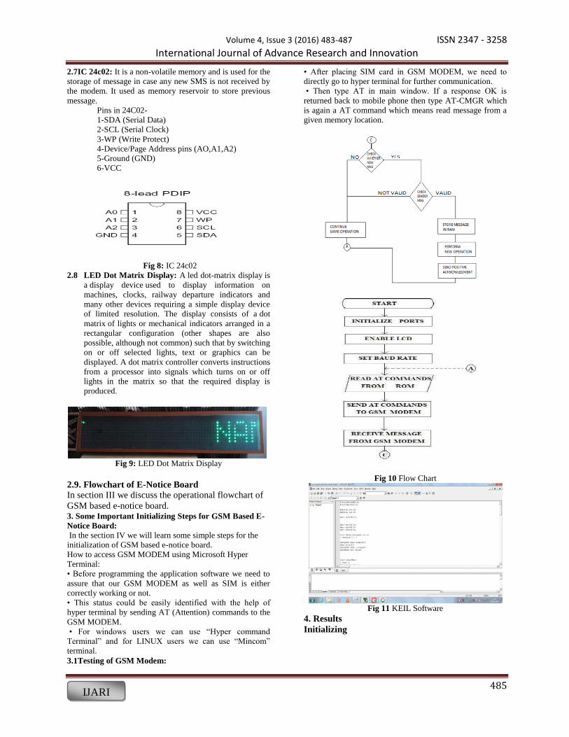
2.9. Flowchart of E-Notice Board
In section III we discuss the operational flowchart of
GSM based e-notice board. 3. Some Important Initializing Steps for GSM Based E-
Notice Board:
In the section IV we will learn some simple steps for the
initialization of GSM based e-notice board.
How to access GSM MODEM using Microsoft Hyper
Terminal:
• Before programming the application software we need to
assure that our GSM MODEM as well as SIM is either
correctly working or not.
• This status could be easily identified with the help of
hyper terminal by sending AT (Attention) commands to the
GSM MODEM.
• For windows users we can use “Hyper command
Terminal” and for LINUX users we can use “Mincom”
terminal.
3.1Testing of GSM Modem:
• After placing SIM card in GSM MODEM, we need to
directly go to hyper terminal for further communication.
• Then type AT in main window. If a response OK is
returned back to mobile phone then type AT-CMGR which
is again a AT command which means read message from a
given memory location.
Fig 10 Flow Chart
Fig 11 KEIL Software
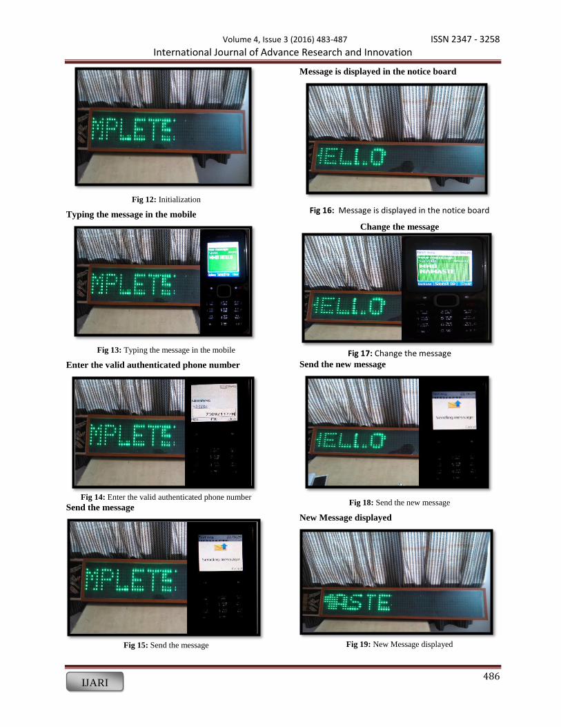
4. Results
Initializing
Volume 4, Issue 3 (2016) 483-487 ISSN 2347 - 3258 International Journal of Advance Research and Innovation
486 IJARI
Fig 12: Initialization
Typing the message in the mobile
Fig 13: Typing the message in the mobile
Enter the valid authenticated phone number
Fig 14: Enter the valid authenticated phone number
Send the message
Fig 15: Send the message
Message is displayed in the notice board
Fig 16: Message is displayed in the notice board
Change the message
Fig 17: Change the message Send the new message
Fig 18: Send the new message
New Message displayed
Fig 19: New Message displayed

Volume 4, Issue 3 (2016) 483-487 ISSN 2347 - 3258 International Journal of Advance Research and Innovation
487 IJARI
3.2 How to Initialize the Microcontroller:
• For initializing the microcontroller with MODEM we need
to use mainly 2 terms named as DTE and DCE.
• DTE – Data Terminal Equipment is a piece of hardware
device for communication.
• DCE – Data Communication Equipment provides the path
for communication.
3.3 Software Environment: 3.3.1KEIL Software for 8051 Family: KEIL – founded in
1982, provides broad range of development tools including
libraries, IDE (Integrated Development Environment),
assemblers and also linkers.
3.3.2 HEX file: HEX file is a special file which is imported
by a programmer into the target IC. Hex file is a kind of file
which is actually not for user.
4. Conclusions The prototype of the GSM based display toolkit was
efficiently designed. This prototype has facilities to be
integrated with a display board thus making it truly mobile.
The toolkit accepts the SMS, stores it, validates it and then
displays it in the LED module. The SMS is deleted from the
SIM each time it is read, thus making room for the next
SMS. The major constraints incorporated are the use of as
the termination character of the SMS and the display of one
SMS as a time.
The GSM based digital notice board system that we have
created has been in practical use in various companies like
in construction companies and research areas, railways,
Colleges.
This technology could be further modified and more
upgraded as per individual need and interest. We have
discussed some basic ideas of this technology. And
depending on innovative applications user can upgrade as
per requirement.
References [1]Janice Gillispie, Mazidi Rolin D. McKinlay, Muhammad
Ali. Book: The 8051 Microcontroller and System
[2] SiegmundRedl, Matthias Weber, Malcolm W. Oliphant.
Books: GSM and Personal Communications Handbook
[3] Pawan Kumar, VikasBhrdwaj, Kiran Pal, Narayan Singh
Rathor, Amit Mishra, GSM based e-Notice Board,
International Journal of Soft Computing and Engineering
(IJSCE).
[4] Agamanolis.S, Digital displays for human connect
endless.In public and situated display Social and
international aspects of shared display technology.
[5] Herman Chung- HwaRao, Di-Fa Chang and Yi-Bing
Lin, ISMS: An Integration Platform for Short Message
Service and IP Networks, IEEE Network, 48-56,
March/April (2001).
[6] Jeff Brown, Bill Shipman and Ron Vetter, SMS: The
Short Message Service, IEEE Computer Society, 106-111,
2007.
[7] QianXu, Evan Wei Xiang, Qiang Yang, Jiachun Du,
JiepingZhong, Agamanolis.S, SMS Spam Detection Using
Noncontent Features, IEEE Computer Society, 44-51, 2012.