GS EP SAF 228 - LIQUID DRAINAGE - POGC · GS EP SAF 228 also addresses the collection and...
66
Exploration & Production This document is the property of Total. It must not be stored, reproduced or disclosed to others without written authorisation from the Company. GENERAL SPECIFICATION SAFETY GS EP SAF 228 Liquid drainage Main Instructor for Derogation: ECP (Process) 03 10/2009 Complete revision 02 10/2005 Addition of EP root to document identification, plus modified section 4.5 and checked for internal consistencies 01 10/2003 Change of Group name and logo 00 04/2001 Old TotalFina SP SEC 228 Rev. Date Notes
Transcript of GS EP SAF 228 - LIQUID DRAINAGE - POGC · GS EP SAF 228 also addresses the collection and...
Exploration & Production
This document is the property of Total. It must not be stored, reproduced or disclosed to others without written authorisation from the Company.
GENERAL SPECIFICATION
SAFETY
GS EP SAF 228
Liquid drainage
Main Instructor for Derogation: ECP (Process)
03 10/2009 Complete revision
02 10/2005 Addition of EP root to document identification, plus modified section 4.5 and checked for internal consistencies
01 10/2003 Change of Group name and logo
00 04/2001 Old TotalFina SP SEC 228
Rev. Date Notes

Exploration & Production
General Specification Date: 10/2009
GS EP SAF 228 Rev: 03
This document is the property of Total. It must not be stored, reproduced or disclosed to others without written authorisation from the Company.
Page 2/66
Contents
1. Scope .......................................................................................................................4 1.1 Purpose of the specification...............................................................................................4 1.2 Applicability........................................................................................................................4
2. Reference documents.............................................................................................5
3. Terminology and definitions ..................................................................................7
4. Design principles for liquid drainage (closed and open drains) .......................10 4.1 The different liquid drainage systems ..............................................................................10 4.2 Effluent categories in open drains ...................................................................................11 4.3 Segregation .....................................................................................................................14 4.4 Drainage piping: diameters, gradients, miscellaneous ....................................................16 4.5 Drainage piping: connections to closed drains and to OD 1 or OD 2 headers ................17 4.6 Drainage piping: material and rating................................................................................17 4.7 Underground facilities (onshore)......................................................................................18 4.8 Toxic service....................................................................................................................18 4.9 Winterisation ....................................................................................................................18 4.10 Accidental spillage ...........................................................................................................19
5. Design of closed drains........................................................................................19 5.1 Maintenance and operation drains ..................................................................................19 5.2 Piping...............................................................................................................................20 5.3 Closed drain drum ...........................................................................................................24 5.4 Standard design...............................................................................................................25 5.5 Minimum installations ......................................................................................................25 5.6 LPG and LNG units closed drain system.........................................................................26
6. Design principles for open drains .......................................................................26 6.1 General ............................................................................................................................26 6.2 Design flows ....................................................................................................................27 6.3 Flow velocities .................................................................................................................28 6.4 Pipe minimum diameters and gradients ..........................................................................29 6.5 Drainage piping: washing/clearing...................................................................................29

Exploration & Production
General Specification Date: 10/2009
GS EP SAF 228 Rev: 03
This document is the property of Total. It must not be stored, reproduced or disclosed to others without written authorisation from the Company.
Page 3/66
6.6 Gas migration and fire spreading.....................................................................................29
7. Design of onshore open drains ...........................................................................30 7.1 Oily water onshore drains typicals ...................................................................................30 7.2 Infiltration .........................................................................................................................31 7.3 Open ditches and channels .............................................................................................32 7.4 The collection of the drainage effluent in process and utility areas .................................32 7.5 Liquid hydrocarbon storage tanks....................................................................................32 7.6 Off-sites ...........................................................................................................................33 7.7 Buildings ..........................................................................................................................33
8. Design of offshore open drains ...........................................................................33 8.1 Configuration of offshore open drains..............................................................................34 8.2 Detailed design of collection system................................................................................35 8.3 Helidecks .........................................................................................................................35 8.4 Buildings ..........................................................................................................................35 8.5 Sump tank and disposal tube ..........................................................................................36 8.6 Minimum installations ......................................................................................................37
9. High volatility hydrocarbon liquids .....................................................................38 9.1 Containment of accidental spillage ..................................................................................38 9.2 Onshore process areas: paving and impounding basins.................................................38 Appendix 1 Accidental spillage flow rate calculation.............................................................41 Appendix 2 Run-off water rates (onshore) (Informative).......................................................42 Appendix 3 Liquid drainage (informative) .............................................................................43 Appendix 4 The collection of the drainage effluent in onshore process and utility areas
(prescriptive) ......................................................................................................................52 Appendix 5 The collection of the drainage effluent in offshore process and utility areas
(prescriptive) ......................................................................................................................60
Exploration & Production
General Specification Date: 10/2009
GS EP SAF 228 Rev: 03
This document is the property of Total. It must not be stored, reproduced or disclosed to others without written authorisation from the Company.
Page 4/66
1. Scope
1.1 Purpose of the specification GS EP SAF 228 defines the safety requirements for liquid drainage facilities in the petroleum installations of the upstream segment of COMPANY’s activities in order to minimise uncontrolled spillage and risk of hydrocarbon ignition and subsequent fire escalation.
The design of oil-contaminated drains, open drains and closed drains, from process, storage and utility areas is the main subject of this GS EP SAF 228. These drains are designed to handle liquid wastes produced in normal operation, any degraded operating modes foreseen during design, and maintenance.
GS EP SAF 228 also addresses the collection and containment of accidental spillage from facilities processing hydrocarbon liquids.
GS EP SAF 228 also aims to minimise direct discharge of polluted streams to the environment by channelling them to appropriated treatment units, in line with COMPANY Environmental requirements as per GS EP ENV 001.
1.2 Applicability New installations designed by or on behalf of COMPANY shall comply with this specification. Modifications and extensions of existing installations should also comply with this specification, unless it is demonstrated and documented that it results in inconsistencies that are detrimental to the overall safety of the installation.
GS EP SAF 228:
• Is not retroactive, but it is used as a reference during the design and operability reviews of the existing oil and gas installations operated by COMPANY affiliates.
• Applies to all onshore and offshore fixed installations handling hydrocarbon liquids in the upstream segment of COMPANY activities, including those handling liquefied gases.
GS EP SAF 228 does not cover:
• Hydrocarbon gases and vapours disposal facilities (covered by GS EP SAF 262)
• Treatment of production water (i.e. water from reservoir) and utility waters (e.g. cooling water, desalting water)
• Containment of accidental spillage from onshore storage facilities (covered by GS EP SAF 341)
• Detailed design of oily water treatment facilities to achieve the specification set for disposal of oily water to the environment
• Design of the facilities treating the effluents not compatible with oily water, such as chemicals, drilling cuttings, solids, domestic sewage
• Collection of LPG/LNG spillage offshore (on deck or on boat)
• Detailed design of the instrument drains (addressed in GS EP INS 900).
• The mobile marine facilities covered by the codes issued by the IMO (International Maritime Organisation)
Exploration & Production
General Specification Date: 10/2009
GS EP SAF 228 Rev: 03
This document is the property of Total. It must not be stored, reproduced or disclosed to others without written authorisation from the Company.
Page 5/66
• The petroleum installations of the COMPANY downstream segment i.e. refinery, marketing and petrochemicals.
The design features that are specific to F(P)SO installations (Floating, (Production) Storage and Offloading) are addressed in GS EP STR 651, and only addressed in this document where additional clarification is necessary.
The drawings and figures contained in this specification are illustrative only and should not be regarded as detailed engineering documents. They illustrate some of the points made in the specification and should be used as a basis for the preparation of detailed engineering drawings.
2. Reference documents The reference documents listed below form an integral part of this General Specification. Unless otherwise stipulated, the applicable version of these documents, including relevant appendices and supplements, is the latest revision published at the EFFECTIVE DATE of the CONTRACT.
Standards
Reference Title
Not applicable
Professional Documents
Reference Title
ISO 10418 / API RP 14C Petroleum and natural gas industries Offshore production installations Basic surface process
ISO 13703 / API RP 14E Petroleum and Natural Gas Industries - Design and Installation of Piping Systems on Offshore Production Platforms
ISO 17776 / API RP 14J Petroleum and Natural Gas Industries - Offshore Production Installations - Guidelines on Tools and Techniques for Hazard Identification and Risk Assessment
ISO 14620 Space Systems - Safety Requirements
API RP 55 Recommended Practice for Oil and Gas Producing and Gas Processing Plant Operations Involving Hydrogen Sulfide
ISO 23251 / API RP 521 Petroleum, petrochemical and natural gas industries Pressure-relieving and depressuring systems
Regulations
Reference Title NFPA 59A Standard for the Production, Storage, and Handling of Liquefied
Natural Gas (LNG)
Exploration & Production
General Specification Date: 10/2009
GS EP SAF 228 Rev: 03
This document is the property of Total. It must not be stored, reproduced or disclosed to others without written authorisation from the Company.
Page 6/66
Codes
Reference Title
IP Code, Part 15 Area classification code for petroleum for installations, part 15 of the Institute of Petroleum Model Code of Safe practice (March 1990)
Other documents
Reference Title
Statement Of Requirements (SOR)
Safety Concept
Operating Philosophy
Total General Specifications
Reference Title
GS EP CIV 202 Drainage and underground networks
GS EP ECP 103 Process sizing criteria
GS EP ENV 001 Environmental Requirements for Projects Design and E&P Activities
GS EP ENV 270 Deep well disposal
GS EP INS 900 Instrument hook-up diagrams
GS EP PVV 112 Piping material classes
GS EP SAF 216 Area classification
GS EP SAF 253 Impacted area, restricted area and fire zones
GS EP SAF 261 Emergency Shut-Down and Emergency De-Pressurisation (ESD & EDP)
GS EP SAF 262 Pressure protection relief and hydrocarbon disposal systems
GS EP SAF 321 Fire pump stations and fire water mains
GS EP SAF 341 Location and protection of onshore hydrocarbon storage
GS EP STR 651 General principles for a F(P)SO Design
Exploration & Production
General Specification Date: 10/2009
GS EP SAF 228 Rev: 03
This document is the property of Total. It must not be stored, reproduced or disclosed to others without written authorisation from the Company.
Page 7/66
3. Terminology and definitions There are five types of statements in this specification, the “shall”, “should”, “may”, “can” and “must” statements. They are to be understood as follows: Shall Is to be understood as mandatory. Deviating from a “shall”
statement requires derogation approved by COMPANY.
Should Is to be understood as strongly recommended to comply with the requirements of the specification. Alternatives shall provide a similar level of protection and this shall be documented.
May Is to be understood as permission.
Can Is to be understood as a physical possibility.
Must Expresses a regulatory obligation
Note that “will” is not to be understood as a statement. Its use is to be avoided, unless it is necessary to describe a sequence of events.
For the purpose of this specification, the following definitions shall apply: API separator Gravity-differential type oil-water separator and auxiliaries designed
according to API recommendations. This is an open pit used onshore in the primary treatment of waste water.
Bunded areas Bunded areas are areas surrounded by embankments and/or bundwalls at or above grade level that are designed for the containment of major accidental spillage and are connected to the open drains via a normally closed valve. "Bund" has the same meaning as the American wording "dike". Not to be confused with drip pans and impounding basins.
Catch basin Catch basins are onshore recessed, grated drainage collection points within a drainage curbed area to channel the surface liquids to the open drain system.
Classified/Unclassified open drains
Classified open drains collect waste oily water from hazardous area (i.e. hydrocarbon liquid production and process areas). Unclassified open drains collect waste oily water from non hazardous area.
Closed drains Closed drains are fully contained drains, hard piped from the equipment to be drained to the treatment facilities.
Cold Flare A cold flare system collects and disposes of cold/dry effluents which are not compatible with warm/wet effluents.
Disposal tube Facility installed in offshore oil and gas installations as the last oil trap before disposal of oily water to sea.
Drip pans Drip pans (or trays) designed to collect, contain and send to the installation drains the oily drips (hydrocarbons, oils, greases) likely to occur underneath process equipment and machines in normal operation. They are permanently connected and lined up to the installation open drain systems. Not to be confused with bunded areas and impounding basins.
Exploration & Production
General Specification Date: 10/2009
GS EP SAF 228 Rev: 03
This document is the property of Total. It must not be stored, reproduced or disclosed to others without written authorisation from the Company.
Page 8/66
Fire break / gas seal U-shaped siphon whose low point is normally filled with liquids, aimed at preventing fire and gas propagation between two different segments of an open drains piping system
GRP To designate the Glass Reinforced Plastics used in the fabrication of piping.
Hazardous area A three-dimensional area in which a flammable atmosphere may be expected to be present at such frequencies as to require special precautions for the control of potential ignition sources (COMPANY from IP Code, Part 15).
High volatility hydrocarbon liquids
Those hydrocarbon liquids which are referred to as Category A petroleum fluids. The criteria for categorising flammable liquids “A” as per the IP code are given in GS EP SAF 216.Basically all liquefied methane and ethane (LNG), all liquefied propane and butanes (LPG), and the more volatile of the rest of Natural Gas Liquids (NGL) belong to this category.
HP flare or HP vent A HP flare or HP vent is a disposal system where the back pressure can be higher than that what is admissible in the LP relief system. The HP flare collects the high flowrate sources which cannot be routed to the LP flare disposal system because they would create excessive back pressure.
Impounding basins Impounding basins are basins below grade level that are designed for the containment of major accidental spillage. They can be equipped with an uplift pump for rainwater removal, but this pump is not intended to transfer hydrocarbon liquids. The impounding basins stand-by are located adjacent to the process equipment, not underneath. Not to be confused with drip pans and bunded areas.
LP flare or LP vent A LP flare or LP vent is a disposal system where the back pressure must be maintained low (maximum 3.5 barg) even at maximum relief flowrate.
Maintenance drains Closed system which collects liquid drains from depressurised equipment and piping. The system is used for maintenance purpose only.
Minimum installations Installations handling oil and gas for production or transport purposes, with no processing facilities. Offshore, they are the wellhead and/or manifold platforms which are not bridged to a process installation. Onshore they are the wellhead clusters and/or production manifolds. A minimum installation may include helideck, (dry) firewater network, electrical cabin, etc. Test separators and pig traps are not considered as processing facilities. Well-Head Platforms or clusters with FWKO drums and water degassing drums are not considered as minimum installations.
Observation basin Facility installed in onshore oil and gas installations as the last oil trap before disposal of oily water to public waters. It is an open pit designed as to retain the drainage effluent for a certain time.

Exploration & Production
General Specification Date: 10/2009
GS EP SAF 228 Rev: 03
This document is the property of Total. It must not be stored, reproduced or disclosed to others without written authorisation from the Company.
Page 9/66
(OD1) Permanently oil-contaminated drains
Waste water open drains contaminated in normal operation by significant quantities of liquid hydrocarbons.
(OD2) Accidentally oil-contaminated drains
Waste water open drains :
• either (1) contaminated in normal operation or during other routine operations foreseen during design (e.g. maintenance) by very small volumes of hydrocarbons so that it is acceptable environmental-wise to route directly the effluents directly to an observation basin or a disposal tube without first separation in API separator or sump tank.
• or (2) normally clean and for which contamination with hydrocarbons can only result from an accidental leak (e.g. piping weld puncture) or a rare event (e.g. storm flooding and cross-contaminating normally clean areas).
(OD3) Oil-free drains Waste water open drains in areas where the risk for contamination by hydrocarbons is minimal and can be disregarded.
Oil trap Facility designed to retain and allow recovery of floating liquid hydrocarbons only. Disposal tubes are offshore final oil traps and observation basins are onshore final oil traps.
Oily water or oil-contaminated water
Waste water generated during the industrial process and which contains oil, emulsified oil, or other hydrocarbons.
Oily water treatment Facilities designed for the treatment (primary, secondary) of oily water to meet a given specification (maximum oil in water content) for its disposal to sea or to public waters.
Open drains They are basically atmospheric drains: their intakes (entry points) are permanently vented to atmosphere.
Operational drains Closed system which collects liquid drains from process equipment and piping whilst the process unit is live and the process equipment and piping is at normal operating pressure.
Paved areas Refers to paving, concrete slabs and other liquid tight surfaces required underneath and around the onshore hydrocarbon process equipment to prevent infiltration into the soil of hydrocarbon liquids (and other pollutants likely to spill).
Primary treatment Gravity-differential separation of oil from waste waters: API separator onshore, or sump tank offshore.
Secondary treatment Facilities designed for the treatment of oily water by means other than gravity-differential separation to meet a given specification (maximum oil content in water) for its disposal to sea or public waters: e.g.: filtration, flotation, chemical flocculation and biological treatment.
Seals, sealed The “seals” are in this specification hydraulic seals. Drains are “sealed” if they are provided with a hydraulic seal to prevent fire spreading and gas migration. This can be implemented either in the piping (siphon) or by entering a capacity below the liquid level.

Exploration & Production
General Specification Date: 10/2009
GS EP SAF 228 Rev: 03
This document is the property of Total. It must not be stored, reproduced or disclosed to others without written authorisation from the Company.
Page 10/66
Self-contained equipment
Equipment provided with a bund designed for containment of a major accidental leak, this bund is connected to the open drains system via a normally closed valve.
Sump tank Atmospheric tank designed as a gravity-differential oil-water separator to treat offshore oil and gas installations oily water drains from the hydrocarbon production and process areas.
Toxic fluids The characteristics of a chemical substance to produce injury once it reaches a susceptible site in or on the body. The effects may be acute or chronic, local or systemic (OGP).The criteria to define a substance as a toxic fluid are set in applicable local regulations and in GS EP SAF 253.
4. Design principles for liquid drainage (closed and open drains) This chapter addresses the basic COMPANY requirements for the design of liquid drainage systems.
4.1 The different liquid drainage systems Drainage systems are networks of pipes collecting liquid wastes from numerous intake points in catchment areas, and transferring these liquids to treatment facilities before safe and controlled disposal (or recycling these liquids into the processing plant).
4.1.1 The different types of effluents In oil and gas production/treatment installations, there are four types of effluents concerned with drainage:
• Waste waters - run-off water (rainfall, fire-fighting and deck/slab washings) polluted or not
- equipment cleaning water (“jetting”, line and vessel cleaning)
- storage water (settling)
• Hydrocarbons - drips and spillage from hydrocarbon process equipment, wireline and other well
servicing activity, and other facilities containing oils and greases
- sampling, draining of process equipment before maintenance
• Chemicals - from the laboratory and other analyses houses
- chemicals used in oil and gas processes
• Sewage - Waste waters from domestic areas (galley, laundry, accommodation and sanitary
facilities).

Exploration & Production
General Specification Date: 10/2009
GS EP SAF 228 Rev: 03
This document is the property of Total. It must not be stored, reproduced or disclosed to others without written authorisation from the Company.
Page 11/66
4.1.2 The different configurations of drainage networks
4.1.2.1 Closed drains Any facility containing hazardous liquids which need to be drained for operational reasons and may not be drained directly to atmosphere without undue risk to personnel, environment or assets from release of flammable or toxic vapours, shall be connected to a closed drain system. In particular:
• Hydrocarbon process equipment and/or piping operated under pressure
• Equipment containing toxic fluids as defined in section 4.8
• Equipment containing high volatility hydrocarbon liquids which require draining for maintenance / inspection purposes.
The design of closed drains is detailed in chapter 5.
4.1.2.2 Open drains They are basically atmospheric drains collecting the surface waste liquids: all their intakes (entry points) are permanently vented to atmosphere.
For safety reasons the facilities containing hydrocarbon flashing fluids under pressure, toxic fluids or high volatility hydrocarbon liquids shall not be drained to an open drain system.
4.1.3 Particular cases
4.1.3.1 Instrument drains The design features that are specific to instrument drains are addressed in GS EP INS 900.
The nominal size of instrument drains is normally much smaller than vessel and piping drains.
All instrument drains shall however comply with the basic principles laid down in sections 4.2 and 4.3.
Note that vessel standpipe drains shall be regarded as vessel/piping drains and therefore shall comply with this specification, whereas level glass should be regarded as instrument drains.
4.1.3.2 Sampling For each new project or major revamping, sampling typicals should be developed. As a minimum the Operating Philosophy and/or Safety Concept documents should list the different types of sampling facilities to be implemented. Sampling typicals shall be approved by Company representative and shown on a dedicated P&ID.
Samples from a facility containing hydrocarbon flashing fluids under pressure, toxic fluids shall not be connected to the open drain system. They shall be collected in a closed, sealed container rated to match the facility maximum operating pressure, or if necessary connected to the closed drain system or to a lower pressure process system.
4.2 Effluent categories in open drains
4.2.1 Open drains, permanently oil-contaminated (OD1) OD1 drains are found in hydrocarbon liquid production, process and storage areas.

Exploration & Production
General Specification Date: 10/2009
GS EP SAF 228 Rev: 03
This document is the property of Total. It must not be stored, reproduced or disclosed to others without written authorisation from the Company.
Page 12/66
OD1 waters shall be treated in a purposely designed oily water treatment unit containing a primary treatment unit as a minimum, and if necessary a secondary treatment before disposal.
OD1 sources include :
• Liquid collected underneath the oil or gas/condensate process equipment likely to produce drips in routine operation (e.g. pumps, compressors, vessels, HC wellheads, manifolds, sampling devices and generally all the equipment with a concentration of non-welded fittings). Such liquid shall be collected in a drip pan.
• Liquid collected underneath oil loading areas including loading arms, hose handling areas at jetties and filling points
• Water draw-off from oil storage tank bottoms
• Water from oil laboratory and analyser houses (they require an independent collection system, see section 4.2.4)
• Drainage from oil sample points (not of fluid cat. A)
4.2.2 Open drains, accidentally oil-contaminated (OD2) They are waste water open drains.
Before disposal to the environment, OD2 waters shall be treated and, as a minimum, floating oil recovered in an oil trap (offshore: an oily water disposal tube designed as per section 8.5.2, onshore: an observation basin designed as per section 7.1.1).
OD2 sources include :
• In plants processing hydrocarbons liquids: waste waters collected in the vicinity of process units i.e. (i) offshore: the deck drains, (ii) onshore: the paved areas.
• In plants not handling hydrocarbon liquids: waste waters collected in areas polluted with lube oils and greases from machines such as power generation, water injection pumps or other equipment (e.g. transformer using insulating oil), subject to segregation requirements set in section 4.2.4.8.
• Oil and condensate storage tank bunds waste waters
• Cooling waters that may be polluted with oil
4.2.3 Open drains, oil-free (OD3) OD3 water may be discharged directly into the environment (offshore through an outfall pipe discharging directly to sea, onshore through a pipe or a ditch discharging directly to public waters)
OD3 sources include :
• Offshore: the “clean” decks e.g. lay-down areas, peripheral areas away from the process equipment (e.g. outside process and utility modules), and the rooves of modules and shelters
• Onshore: the green belt, undeveloped areas, building rooves (buildings outside the process area).

Exploration & Production
General Specification Date: 10/2009
GS EP SAF 228 Rev: 03
This document is the property of Total. It must not be stored, reproduced or disclosed to others without written authorisation from the Company.
Page 13/66
4.2.4 Effluents not compatible with OD1, OD2 and OD3 sources This section lists the main types of wastes encountered in oil and gas production and treatment facilities that shall not be mixed with waste waters collected in the installation open drains without prior adequate treatment.
The effluents which are toxic for health or the environment and cannot be treated on site, shall be stored in adequate sealed containers, and then transported to appropriate treatment facilities outside the installation.
4.2.4.1 Domestic sewage A dedicated collecting network and specific treatment units (e.g. degreaser) are required to handle wastes from living quarters, kitchen and sanitary facilities. Domestic waste waters shall not be mixed with other drainage effluents or disposed of before appropriate treatment.
4.2.4.2 Laboratories Laboratory sink drains handle oily products but also chemically polluted effluents, which shall not be sent directly to the installation open drain system. The laboratory drains shall be piped independently from other drains to a dedicated, vented atmospheric tank.
These wastes must be processed in one of the following ways:
• Treated (secondary treatment like neutralisation), or
• Stored before transport to an appropriate treatment facility.
The solution should be selected depending on the regulatory requirements and plant design. The selected design shall be approved by COMPANY.
4.2.4.3 Chemical storage Permanent storage containing hazardous chemicals incompatible with water shall be provided with bunds to safely contain minor spillage and major accidental leaks. The contained spillage should then be treated (e.g. using one of the methods defined in section 4.2.4.2). The method selected shall be approved by COMPANY.
4.2.4.4 Sour water/Chemically polluted streams Sour Water streams (e.g. containing H2S or NH3) shall be stripped in a sour water stripper, unless otherwise specified by COMPANY. Further treatment may be necessary before they can be discharged to the main oily water treatment system.
Units handling:
• Methanol, glycol, amines
More generally any chemical that cannot be separated by gravity from wastewaters, shall not be drained to the installation open drain system. Their wastewaters and drips shall be collected and stored independently for further handling (e.g. recycling to the process, dedicated secondary treatment).
4.2.4.5 Water contaminated with acids Such waters shall be neutralised, as near as possible to the source.

Exploration & Production
General Specification Date: 10/2009
GS EP SAF 228 Rev: 03
This document is the property of Total. It must not be stored, reproduced or disclosed to others without written authorisation from the Company.
Page 14/66
4.2.4.6 Water containing agents that can impair gravity separation Streams that can impair gravity separation, such as streams containing solids, emulsifying agents and/or contaminants that tend to flocculate upon dilution shall:
• Not be mixed with oily water
• Be treated and/or disposed of separately, as specified by COMPANY.
Falling in this category are the “jetting” waters which are used to clean vessel internals to prevent accumulation of sands and sediments. A specific collecting network, independent from the other open drains, shall be provided. Jetting waters shall be washed and filtered before allowing them to drain in the installation OD2 drains.
4.2.4.7 Cold drains Drainage of cold effluents which, mixed with wastewater at ambient temperature, may lead to icing shall be collected in dedicated piping. Treatment, de-oiling, should also be performed in dedicated facilities, unless it is demonstrated that mixing cannot lead to icing in the equipment shared by the cold and humid effluents.
4.2.4.8 Machinery space Many regulations and best practices require that, for environmental purposes, oily waters from machinery spaces, involving lube oils with metallic contents, are handled separately from other oils. This segregation shall be addressed in the Safety Concept.
4.2.5 High volatility hydrocarbon liquids High volatility hydrocarbon liquids shall not be drained to an open drain system. For the containment of accidental spills from facilities containing such liquids refer to chapter 9.
4.3 Segregation As shown in section 4.2, drainage systems carry a large number of different effluents. Improper segregation of drainage systems is one of the main causes of accidents in oil and gas installations. Segregation must therefore be incorporated as early as possible in the design of drainage systems.
4.3.1 Segregation: Closed drains/Open drains Closed drains shall always be segregated from open drains in order to prevent pressure-driven gas from the closed drains coming back up into the plant via the open drains system.
The piping networks collecting closed drains and open drains shall be independent (no inter-connections at all, even for maintenance purposes).
The closed drain drum shall receive no effluents from the open drains collection network. The closed drain drum shall not discharge into an atmospheric enclosure (tank, drum) receiving open drain effluents.
4.3.2 Segregation: Hazardous/Non hazardous areas The risk of sending hydrocarbons from areas categorised “hazardous” (as per GS EP SAF 216) to areas categorised “non-hazardous” shall be minimised by segregation of the systems draining these areas.
Exploration & Production
General Specification Date: 10/2009
GS EP SAF 228 Rev: 03
This document is the property of Total. It must not be stored, reproduced or disclosed to others without written authorisation from the Company.
Page 15/66
The piping networks collecting open drains from hazardous areas and from non-hazardous areas shall be independent (no inter-connections at all, even for maintenance purposes). This principle applies to all open drains, including the instrument open drains.
Drain headers from hazardous and non-hazardous areas may all discharge into a common oil trap or primary treatment facility provided both conditions below are met:
• Headers from hazardous areas are not connected to headers from non-hazardous areas and each header enters the common treatment facility via its own dedicated inlet nozzle.
• Hydraulic seals are provided at the oil trap/primary treatment facility by means of an inlet pipe discharging below the liquid level in the facility (the drain header from non-hazardous areas shall be sealed at entry with 1 m water depth minimum).
4.3.3 The segregation requirement for drip pans A drip pan shall be provided underneath every process and utility facility likely to pollute waste water during routine operation.
Generally catchment areas should be arranged in order to prevent mixing of effluents that require different treatment methods.
Open drainage systems shall be arranged and sized to prevent flooding of the drip pans and the spread of fire and flammable liquids from one catchment area to another. There shall be no carry-over:
• From the drip pans to the adjacent deck (offshore) or grade (onshore)
• From one deck to the deck located below (offshore).
To achieve this, the open drain systems shall be capable of handling the design flows which are defined in section 6.2.
The arrangements of OD1, OD2, OD3 drains are detailed in chapter 7 for onshore installations and chapter 8 for offshore installations.
4.3.4 The segregation requirement for paved areas In onshore installations, paved areas shall be provided in process areas in order to:
• Prevent infiltration of oily effluents into the soil
• Minimise the evaporation rate of hydrocarbons liquids and thus the extent of the flammable gas cloud.
Paved areas shall be split into spillage catchment areas :
• Spillage catchment areas should be arranged in order to prevent mixing of effluents that require different treatment methods.
• Spillage catchment areas shall be arranged in order to prevent mixing of effluents that require non compatible methods for vapours control and fire-fighting.
• The location, size and shape of the spillage catchment areas shall be such that the effects of a pool fire of the size of one spillage catchment area can be controlled. The fixed and mobile active fire-fighting systems, and the passive fire protection of equipment and structures shall be defined accordingly.
Exploration & Production
General Specification Date: 10/2009
GS EP SAF 228 Rev: 03
This document is the property of Total. It must not be stored, reproduced or disclosed to others without written authorisation from the Company.
Page 16/66
Open drainage systems shall be arranged and sized to prevent flooding of the spillage catchment areas and the spread of fire and flammable liquids from one catchment area to another. There shall be no carry-over:
• From one spillage catchment area to the adjacent spillage catchment areas
• From paved to unpaved areas
4.3.5 The segregation of cold / wet effluents The collection and treatment of drains shall be segregated such that icing may not occur: cold drains (handling LNG, refrigerated LPG or NLG) shall not be mixed with wet drains.
4.4 Drainage piping: diameters, gradients, miscellaneous The design of the drainage systems should minimise the presence of stagnant hydrocarbon mixtures (liquids, emulsions, and solid residues) on surfaces and inside the collection system.
Evacuation of drainage effluents shall be by gravity. Drainage headers are normally laid horizontally with sizes and gradients in order to ensure proper evacuation. The open drain systems shall be capable of handling the design flows defined in section 6.2.
Maximum capacity of open drain horizontal headers shall be in accordance with GS EP CIV 202.
The system shall be designed to prevent any flooding of paved areas, floors or decks around control rooms, technical rooms (containing instrument or electrical equipment) and furnaces.
Restrictions, fittings and generally piping routings with a high resistance to flow should be avoided (special rules apply to closed drains, see chapter 5).
Other than siphons and seal pots (or manholes onshore), drainage headers shall contain no pockets and slope continuously towards the primary treatment, oil trap or sump tank.
4.4.1 Piping diameter Piping diameters depend on service (see chapter 5 for closed drains piping diameter and chapter 6 for design velocities in open drains piping).
The nominal diameter of drainage headers, open and closed, in onshore and offshore installations shall not be less than 3”.
Onshore the minimum nominal diameter of oily water open drain headers shall be in accordance with GS EP CIV 202, 4” for branches less than 15 m and for headers collecting a maximum of 4 drains, otherwise it shall be 6” minimum. A minimum of 8” is required for drainage sewer between manholes (sub headers).

Exploration & Production
General Specification Date: 10/2009
GS EP SAF 228 Rev: 03
This document is the property of Total. It must not be stored, reproduced or disclosed to others without written authorisation from the Company.
Page 17/66
4.4.2 Piping gradients The minimum gradients of the horizontal piping are specified below for fixed installations (for gravity-type drains, non-flooded pipes):
Type of installation Line size Minimum gradient
Onshore Ø ≥ 18”
18” > Ø ≥ 6” 6” > Ø ≥ 3”
0.2% 0.4%
1.25%
Offshore pre-fabricated module Ø ≥ 3” 1% + hook-up tolerances
Offshore Ø ≥ 3” 1%
Note that F(P)SO may require higher gradients to make up for vessel movements.
4.5 Drainage piping: connections to closed drains and to OD1 or OD2 headers The level of risk of plugging of the open and closed drain headers by solids (sand etc.), deposits (wax etc.) or high viscosity fluids shall be identified where credible in the Safety Concept.
Based on this, the type of connection from drain branches or sub headers to drain headers can be made either:
• At 90 degrees, but in this case rodding points shall be provided for each header at risk
• At an angle of 45 or 60 degrees.
4.6 Drainage piping: material and rating Drainage piping material and rating shall be selected as per specification GS EP PVV 112.
4.6.1 Closed drains The piping material shall be steel, either carbon or alloy depending on service.
GRP (Glass Reinforced Plastics) shall not be used for this service. For pressure ratings refer to chapter 5.
4.6.2 Open drains Piping shall be class 150# ANSI.
Oil-contaminated water OD1 and OD2 drains piping material should be either steel or GRP depending on service.
Oil free water OD3 drains piping material should be either GRP, concrete or steel.
Oil-free water may be collected in open channels/ditches.

Exploration & Production
General Specification Date: 10/2009
GS EP SAF 228 Rev: 03
This document is the property of Total. It must not be stored, reproduced or disclosed to others without written authorisation from the Company.
Page 18/66
4.7 Underground facilities (onshore) Tanks and vessels handling hydrocarbon liquids shall not be installed in excavated pits.
When installation underground or below grade level is necessary, the gap between the facility and the pit shall be filled with dry sand, and suitable protection against rain shall be provided.
Burying those tanks and vessels may be an acceptable alternative only if :
• They are of a double containment fabrication type to minimise the risk of an unnoticed leak to the environment
and if
• They are provided with suitable protection to avoid rainwater percolation.
4.8 Toxic service Substances regarded as toxic shall not be exposed to personnel without due precaution being taken.
Process streams containing hydrogen sulphide (H2S) are regarded as toxic and shall not be released intentionally to atmosphere if any one of the following conditions is met:
• The concentration of H2S in the gas on release (1) is 100 ppm (2) or more,
• In inadequately ventilated (3) areas the concentration of H2S in the gas on release is 5 ppm (4) or more.
A similar approach shall be adopted for other toxic material (e.g. SO2, CO, CO2, Cl2, disulfides, mercaptans, BTEX, refer to GS EP SAF 253), for which concentration in the gas on release shall be validated by COMPANY.
• Facilities handling such toxic streams shall:
• Not be drained to an open drain system
Be drained to a closed drain system. (1): The “gas on release” is the gas flashing from the process liquid at atmospheric and ambient temperature.
(2): Corresponding to the IDHL of H2S (Refer to GS EP SAF 253).
(3): With regards to H2S concentration, an area is defined as inadequately ventilated when the ventilation (natural or artificial) is not sufficient to prevent the accumulation of significant quantities of H2S-Air mixtures in excess of 10 ppm (definition from API RP 55). For example areas with 100% plain walls and either 100% plain ceiling or 100% plain floor shall be regarded as inadequately ventilated. Typical examples are pits and depressions. For further guidance on areas inadequately ventilated refer to GS EP SAF 216.
(4): Corresponding to the TLV TWA of H2S (refer to GS EP SAF 253)
4.9 Winterisation Where applicable, drainage lines, seal pots and headers shall be winterised against freezing by heat tracing or alternate solutions.
Exploration & Production
General Specification Date: 10/2009
GS EP SAF 228 Rev: 03
This document is the property of Total. It must not be stored, reproduced or disclosed to others without written authorisation from the Company.
Page 19/66
4.10 Accidental spillage Provisions for mitigating the effects of an accidental spillage should be considered below and around any facilities containing combustible, flammable liquids.
These provisions are widely dependent on the type of the liquid, the type of the facilities, their size and inventory, and their location. It is not the purpose of this present document to give detailed solutions for all cases.
The specific case of onshore facilities handling highly volatile hydrocarbons is further addressed in chapter 9. The specific case of hydrocarbon storage is addressed in GS EP SAF 341. Toxic and environmentally harmful liquids are addressed in section 4.2.4. For others fluids the general principles are:
• A kerb of minimum 150 mm high should be provided around the area under the equipment where potential leakage could occur. This kerbing area could encompass more than one vessel, depending on the layout of the plant. The area contained within the kerbing shall take into account the estimated flow-rate and volume of the liquid lost during a credible event
• In a consistent manner with GS EP SAF 253, the credible leak should be based on a 20mm hole size and a release duration of 10 minutes (see section 6.2.5)
• Onshore the liquids caught in the kerbed area should preferably be routed to a dedicated impounding basin via open ditches and by gravity flow. Alternatively these liquids can be connected to the open drain system.
• Offshore the liquids caught in the kerbed area shall be routed to the open drain sump tank as shown in Appendix 3, Figure 3C.
• Finger-type slug catchers shall be provided with a paved area underneath their liquid bottle sections. This paved area shall slope to an impounding basin whose capacity shall accommodate the maximum liquid volume of the slug catcher, and which is not located underneath the slug catcher.
5. Design of closed drains
5.1 Maintenance and operation drains Closed drains shall be designed as per the requirements set out in chapters 4 and 5.
Closed drain systems are principally designed for the collection of maintenance drains, but can be designed for operational drains with the provisions given below.
5.1.1 Maintenance drains The closed drain system connects drains used for maintenance purposes, i.e. to drain a facility after it has been isolated and depressurised (the residual pressure before drainage shall not exceed 3.5 barg).
These closed drains shall be referred to as maintenance drains.
Exploration & Production
General Specification Date: 10/2009
GS EP SAF 228 Rev: 03
This document is the property of Total. It must not be stored, reproduced or disclosed to others without written authorisation from the Company.
Page 20/66
5.1.2 Operation drains Liquids from process equipment are routed to other process units.
It may be accepted to route liquids from process equipment to the closed drains system only where transferring these liquids to process facilities is impractical e.g.:
• Facilities which would produce small liquid volumes at very low pressure in remote locations (e.g. vent and flare piping low points on some onshore installations)
• Facilities which would release very small liquid volumes infrequently (e.g. compressor casing drains to sweep liquids out before starting, fuel-gas filters).
Automatic transfer of liquids from a flare KO drum to the closed drain drum may be accepted if gas blow-by and high level in the closed drain drum safeguards are in place. A dedicated nozzle should be provided on the closed drain drum.
These closed drains shall be referred to as operation drains.
Manual operation drains (i.e. that can be operated only manually) shall be justified by Project in an auditable document.
Automatic operation drains (i.e. that can be operated without operator manual intervention) shall require a derogation to this specification duly approved by COMPANY.
All operation drains shall be highlighted on the P&ID and in the project OPERATING PHILOSOPHY: a note shall state their design intent.
The above rules related to operational drains shall also be applied to VENDOR packages.
5.2 Piping The lines collecting closed drain effluents are referred to as piping in this chapter.
5.2.1 General Closed drain piping shall comply with COMPANY hydrocarbon piping specifications (refer to GS EP PVV 112), in particular buried sections shall be all-welded (no flanges).
Closed drain lines shall slope continuously down to the closed drain drum (see section 5.3). There shall be no low points in the piping.
All the consequences of a gas blow-by scenario (effect on drain line design temperature and pressure, and effect on flare/vent line diameter from the closed drain drum, and safety distances around flare/vent) shall be considered in the design of closed drains not positively isolated from the process equipment to which they are connected.
• Positive isolation can be a spectacle blind (in closed position), a blind flange or a removable spool piece.
Care shall be taken that back pressure from high pressure drains cannot impair low pressure drains and their connected equipment.
The closed drains not fitted with positive isolation should be carefully considered; these are :
• The operation drains
• Some of the maintenance drains (see section 5.2.5 and Figure 1).

Exploration & Production
General Specification Date: 10/2009
GS EP SAF 228 Rev: 03
This document is the property of Total. It must not be stored, reproduced or disclosed to others without written authorisation from the Company.
Page 21/66
5.2.2 Diameter The nominal diameter of headers shall not be less than 3”. When determining the diameter of the piping, possible occurrence of multi-phase flow shall be considered.
For more details on the design of the branches connecting drain points to the headers, see sections 5.2.5 and 5.2.6.
5.2.3 Design pressure The piping upstream of the closed drain drum shall be rated to match the highest design pressure of the process facilities to which it is connected. This rule applies to all types of closed drains, including those fitted with a spectacle blind for positive isolation from the process equipment.
Mixing LNG with warmer, high volatility liquids (e.g. LPG or NGL) may result in serious vacuums with a potential for piping collapse. LNG shall not be mixed with such liquids, unless piping and vessels are designed to withstand the resulting vacuum.
The closed drain collection piping may be segregated into sub-systems of different piping classes; in that case, each sub-system shall be provided with an independent header connected to the closed drain drum via a dedicated nozzle.
In the case of modification to an existing facility, preference is given to the upgrade of the whole closed drain system to match the highest design pressure of the process facilities to which it is connected.
The derogation process remains appropriate for any brown field modification where the aspect of the SAF 228 cannot be achieved, e.g. to connect new HP (typically 600 or 900#) closed drain individual lines to an existing LP (typically 150#) closed drain header and subsequent existing closed drain drum.
The derogation dossier shall address at least:
• Existing LP network blockage (e.g. by hydrates, solids, sands, paraffin, asphaltenes)
• Presence of valves on existing LP drain network
• Existing LP closed drain network over-pressurisation
• Assessment of existing individual closed drain lines design and arrangement against the requirements of GS EP SAF 228
• Gas blow by to the existing closed drain drum
• Existing closed drain drum over-pressurisation
• Existing closed drain drum overfilling.

Exploration & Production
General Specification Date: 10/2009
GS EP SAF 228 Rev: 03
This document is the property of Total. It must not be stored, reproduced or disclosed to others without written authorisation from the Company.
Page 22/66
5.2.4 Design temperature For closed drains that are positively isolated from the process equipment, the lowest temperature resulting from (mal operation) drainage under full process pressure shall be considered. The piping material shall be selected to withstand this temperature at the atmospheric pressure only (refer to GS EP ECP 103).
For closed drains that are not positively isolated from the process equipment, the simultaneous occurrence of the lowest temperatures and the highest process pressure shall be considered (see section 5.2.1).
It should be noted that LPG stored under pressure at ambient temperature is prone to contain free water. This water may freeze after the LPG flashes in the drain system. Piping and vessels in LPG drainage systems prone to contain water shall be protected against the risk of icing e.g. with heat tracing.
5.2.5 Maintenance drains connections The connection of a maintenance drain to a process facility shall be designed as per the drawings of Figure 1, and the requirements of the present section.
Branches connecting the process facilities (e.g. hydrocarbon piping and vessels) to closed drain headers shall be :
• Of a 2” nominal diameter, as a minimum
• Fitted with a full bore ball (or gate) valve located as close as practicable to the facility to which it is connected.
• Fitted with a spectacle blind, associated with a bleed to vent gas that could be trapped between the ball valve and the spectacle blind. This bleed shall discharge into an open drain intake for all facilities provided with a drip pan. For the other facilities such as piping header this is recommended but not mandatory.
• Fitted with a globe valve located downstream of the spectacle blind. The diameter of the globe valve may be reduced to decrease the flow in case of gas blow-by scenario.
• Fitted with a check valve located between the spectacle bind and the globe valve to prevent gas return when spectacle blind is opened.
To optimise the number of valves and flanges (sources of leaks) multiple drain connections from the same equipment or unit to a single drain connection is acceptable provided that all above principles are followed.

Exploration & Production
General Specification Date: 10/2009
GS EP SAF 228 Rev: 03
This document is the property of Total. It must not be stored, reproduced or disclosed to others without written authorisation from the Company.
Page 23/66
ODCD
FLAMMABLE (CAT. B OR C)& NON TOXIC
LC 2" Process liquids
CAT. A (LNG, LPG, NGL)OR TOXIC
2" LC or CSC Process liquids
(2)
(3)
3" x 2"
600m
m m
ini
(1)
(4)
(2)
CD
3" x 2"
600m
m m
ini
(1)
(5)
OD
NON FLAMMABLE & NON TOXIC
2" LC (3) Process liquids
(3)
Process liquids
FLAMMABLE (CAT. B OR C)& NON TOXIC
CLEAN SERVICE (6)
(2) 2"
(3)
ODCD
(4)
600m
m m
ini (
1)
Legend :FLAMMABLE, CAT., LNG, LPGTOXIC relate to the materials handled by the equipmentCD : Closed Drains SystemOD : Open Drains SystemLC : Locked ClosedCSC : Car Seal Close
full bore block valve
globe valve
Figure 1 - Maintenance drains connections
Notes:
Important note: The drawings and figures contained in this specification are illustrative only and should not be regarded as detailed engineering documents. They illustrate some of the points made in the specification and should be used as a basis for the preparation of detailed engineering drawings.
General note: Figure 1 is to be used in conjunction with section 4.8; 2” and 3” are minimum nominal diameters.
(1): Minimum distance required if icing is a possibility during drainage.
(2): First block valve (ball or gate) as close as possible to equipment, straight line, no elbow from equipment to last valve to open drains.
(3): Valve to open drains shall be blanked off with a blind flange (valve can be used to bleed pressure before turning the spectacle blind).
(4): If the close drain connection is from a line rather than an equipment item, a dedicated connection to the open drains is not mandatory.
(5): A spacer or a spectacle blind normally in open position is necessary to ensure that positive isolation means are readily available for the maintenance/inspection activities.
(6): For vertical and or horizontal vessels in clean service, it is acceptable that the drain connection is on the process liquid outlet line, upstream or downstream of the liquid outlet automatic isolation valve if any.

Exploration & Production
General Specification Date: 10/2009
GS EP SAF 228 Rev: 03
This document is the property of Total. It must not be stored, reproduced or disclosed to others without written authorisation from the Company.
Page 24/66
Figure 1 assumes that all process equipment, including lines, are provided with adequate depressurisation facilities. If an item of equipment is designed to be depressurised via a remote facility connected to flare or vent (e.g. flow-line depressurisation via a test separator to a flare) this shall be noted on the P&ID for clarification purposes. Typically dedicated cleaning/flushing nozzles (inlet and outlet) are provided and not shown on this sketch.
5.2.6 Operation drains connections The design of operation drains connections shall be studied on a case by case basis and shall be approved by COMPANY. As for all process facilities a safety analysis shall be performed (as per ISO 10418 / API RP 14C and GS EP SAF 261) and appropriate shutdown devices incorporated in the design. The gas blow-by scenario shall be considered for the design of closed drain facilities collecting operation drains.
The minimum nominal diameter of piping and block valves shall be 2” to prevent blockage. To decrease the flow in the event of a gas blow-by the nominal diameter of throttling or control valves may be reduced.
5.3 Closed drain drum
5.3.1 Purpose Closed drains shall discharge first into a flash drum, referred to as the closed drain drum. The closed drain drum shall be designed as a flash drum for the closed drain effluents, and shall have no other function.
5.3.2 Venting The closed drain drum should be connected to the LP (Low Pressure) flare. It may be connected to a LP vent, if there is no LP flare on the installation. It shall not be connected to a HP (High Pressure) flare or vent which may cause undue back-pressures in the closed drain network.
The closed drain drum and its gas relief outlet piping shall accommodate the largest flow resulting from the largest gas blow-by occurring in one single drain not isolated from the process equipment by a positive isolation (see section 5.2.1).
5.3.3 Design pressure The design pressure of the closed drain drum shall be 3.5 barg or LP flare design pressure which may be governed by internal explosion resistance, refer to GS EP SAF 262.
All facilities connected to a closed drain drum shall be designed at no less than the design pressure of the closed drain drum.
Design shall ensure that all risks of vacuum or air entry are properly addressed.
Purging requirements: refer to GS EP SAF 262.
5.3.4 Design temperature The same rules shall apply for the closed drain drum as for the drainage collection piping (refer to section 5.2.4).

Exploration & Production
General Specification Date: 10/2009
GS EP SAF 228 Rev: 03
This document is the property of Total. It must not be stored, reproduced or disclosed to others without written authorisation from the Company.
Page 25/66
5.3.5 Design capacity The capacity of the closed drain drum depends on the drainage philosophy which shall be defined in the Operating Philosophy. As an absolute minimum, the closed drain drum shall be capable to handle the maximum liquid inventory from a single vessel at LSLL. Specific cases shall be addressed in the Operating Philosophy.
5.3.6 Miscellaneous The closed drain drum shall have no connection for liquid transfer directly to mobile facilities (e.g. offshore: to a boat). Such transfer, if necessary, shall be done from a dedicated downstream atmospheric tank or pit.
In case of operational drainage, a LSHH shall be installed to shut off all operational drains lines. In case of manual maintenance drainage, a LAH and visible and audible alarms in the workplace shall be provided as a minimum.
For the automatic shutdown actions in case of LSHH, refer to GS EP SAF 261.
5.4 Standard design Appendix 3, Figure 3C illustrates the application of chapter 5 for an offshore platform.
The standard design shall apply to all COMPANY installations which are not regarded as “minimum installations” (defined in chapter 3).
Closed drain drum liquids should be returned (pumped back) directly to the LP process.
If sending closed drain drum liquids back to the process is not practicable (e.g. onshore if the drum is located far from the process), the closed drain drum liquids can be sent to oily water treatment. Closed/open drains segregation rules defined in section 4.3 shall be followed.
In particular:
• Offshore: No open drain headers shall be connected to a tank or vessel receiving the closed drain drum liquids. Another tank shall be dedicated to collect open drains. • Onshore: An API separator or other open pit may receive closed drain drum liquids and oily water from the open drains. Liquid seals shall be provided at the inlet to counter balance the maximum anticipated back pressure from the closed drains side (the open drain header inlet shall be submerged at no less than 1 meter under the liquid level).
5.5 Minimum installations A simpler design may be adopted for the minimum installations.
Appendix 3, Figure 3D illustrates the application of section 5.5 for an offshore minimum installation platform.
Appendix 3, Figure 3I illustrates the application of section 5.5 for an onshore minimum installation.
A single vessel may be designed and used as both LP flare/vent KO drum and closed drain drum, if this vessel complies with the requirements of section 5.3 and if both conditions below are met:
• There is a LP flare/vent network, which is independent from the HP flare and low temperature flare network, and whose operation back pressure cannot exceed 3.5 barg

Exploration & Production
General Specification Date: 10/2009
GS EP SAF 228 Rev: 03
This document is the property of Total. It must not be stored, reproduced or disclosed to others without written authorisation from the Company.
Page 26/66
• The drain headers tie directly into the LP flare/vent KO drum via dedicated nozzles, and are not connected to the LP flare/vent piping/header.
Combining LP flare/vent KO drum and closed drain drum shall be accepted only if the Operating Philosophy clearly states that any maintenance drainage or liquid disposal to mobile facility is made after the installation is shut-down in such a manner that LP flare/vent receives no more flow. If installation shutdown is not the selected option, liquids offloading to mobile facilities shall be made via a dedicated downstream atmospheric tank or pit.
This design is acceptable if all the requirements listed below are met (otherwise the standard design of section 5.4 shall be adopted):
• The combined LP flare and closed drain drum is permanently vented through a flare stack or vent designed in accordance with GS EP SAF 262. In the case of a vent both systems (LP vent system and closed drain system) are designed for internal explosion.
• The drain headers inlets to the combined LP flare/vent and closed drain drum are made with dip pipes with a minimum liquid seal of 300 mm in order to prevent gas return flow when turning the closed drain spectacle blind.
• No operation drains are connected to the closed drain drum
• The closed drain drum is not connected to another process facility nor to a HP vent whose back-pressure can exceed 3.5 barg.
• The closed drain drum receives no effluents from the open drain system.
• The closed drain drum liquids are sent back to the process by pumps.
Liquids offloading to mobile facilities, if any, shall be made via a dedicated downstream atmospheric tank or pit.
5.6 LPG and LNG units closed drain system For requirements specific to category A fluids (LNG and LPG), refer to section 9.
LNG and LPG closed drains may discharge directly into the KO drum of a LP cold flare. LNG and LPG drains shall not be mixed with other drains until they enter the flare drum. Also LPG and LNG drain and flare systems shall be segregated, because of the vacuum hazard (see section 5.2.3)
6. Design principles for open drains
6.1 General Open drains shall be designed as per the requirements set out in chapters 4 and 6. Further requirements are developed in chapter 7 for onshore open drains and in chapter 8 for offshore open drains.
This section is not applicable to the units handling high volatility hydrocarbon liquids which shall not be provided with open drainage systems for normal operation (refer to chapter 9).
The open drainage systems should be kept as simple as possible in terms of construction, operation and maintenance.
Exploration & Production
General Specification Date: 10/2009
GS EP SAF 228 Rev: 03
This document is the property of Total. It must not be stored, reproduced or disclosed to others without written authorisation from the Company.
Page 27/66
For onshore installations: open, gravity-based drainage systems shall be used for the drainage of waste water, unless they are prohibited by local regulations. Alternatives to gravity-based drainage systems (e.g. flooded systems) shall require COMPANY’s approval.
6.2 Design flows The loading on a drainage system consists mainly of:
• Rainwater (Qr)
• Fire-fighting water (Qf)
• Washdown water (Qw)
• Effluent (Qe)
• Accidental spillage (Qa)
Drainage system shall be designed for the greatest of the following cases:
• Firewater case = Qf + Qe
• Rainwater case = Qr + Qe
• Washdown case = Qw + Qe
• Accidental spillage case = Qr + Qa
These flows are described in details below.
6.2.1 Rainwater Peak rainfall data over a selected return period should be used where available and justified.
Onshore, 95% of the paved areas surface should be used to estimate the rainfall drainage to the open drains system. The contribution of run-off from unpaved areas should be considered on a case by case basis using the guidance given in Appendix 2.
Offshore, a minimum rainwater rate of 0.05 l/s.m2 shall be used, if not exceeded by rainfall records over the reference return period. The surface to be taken into account is:
• On the highest deck (referred to as weather deck), the total surface
• On lower decks, strips with a width equal to the elevation between two consecutive decks (based on rainfall at an angle of 45°)
6.2.2 Fire-fighting water The calculation of the quantity of fire-fighting water to be discharged through the drainage system shall be based on the assumption that:
• Only one fire zone (definition in GS EP SAF 253) is subject to a fire at any one time
• Fire water used for the protection of “self-contained” equipment is contained in the bund.
The most demanding fire scenario, excluding fires in “self-contained” equipment, shall be selected.
Unless detailed hydraulic calculations are available, the fire water flow to be evacuated shall be taken as the fire water demand, as calculated by GS EP SAF 321, multiplied by a factor of 1.25.

Exploration & Production
General Specification Date: 10/2009
GS EP SAF 228 Rev: 03
This document is the property of Total. It must not be stored, reproduced or disclosed to others without written authorisation from the Company.
Page 28/66
No credit shall be taken for loss of sprayed firewater through evaporation, etc
6.2.3 Washdown water A rate of no less than 50 m3/hr (washdown hose capacity plus some contingency) shall be considered.
6.2.4 Effluent All the flows other than mentioned in sections 6.2.1 through 6.2.3. Mainly: the water draw-off from hydrocarbon storage tanks, the effluent volumes from the final draining/emptying of the process facilities that cannot be sent to the closed drains. This flow is usually marginal compared to firewater and rainwater flows, with the exception of bottom tank water from the onshore large hydrocarbon storage tanks.
In the absence of any specific figure, a value of 30 m3/h can be used.
6.2.5 Accidental spillage The accidental spillage flow-rate and volume design shall be defined as the lesser of:
• The total liquid lost in 600 seconds through a 20mm diameter hole from any equipment of a kerbing area (see section 4.10) or,
• The normal liquid volume of the biggest vessel of the kerbing area.
The accidental spillage flow-rate should be calculated with the formula in Appendix 1.
6.3 Flow velocities Velocities shall be kept within a range that allows self-cleansing, prevents emulsification and damage to the pipe and fittings (erosion).
6.3.1 Minimum The introduction of solids into drain pipes cannot be avoided and this is prone to produce silting in the pipes.
A minimum velocity of 0.8 m/s, either from process effluent flows alone, or from combined process and rainwater flows shall be attained a minimum of six times per year to achieve periodic cleansing of the drains. If it cannot be obtained though process or rainwater flows, flushing facilities shall be provided to meet the requirement in each pipe run of the system.
In drain pipes where heavy amount of sand or other solids may be present 1.2 m/s shall be the minimum velocity.
6.3.2 Maximum In oily water (OD1 and OD2) and domestic sewage drain pipes, velocities attained should not regularly exceed 2.0 m/s to prevent emulsification.

Exploration & Production
General Specification Date: 10/2009
GS EP SAF 228 Rev: 03
This document is the property of Total. It must not be stored, reproduced or disclosed to others without written authorisation from the Company.
Page 29/66
6.3.3 Flow velocities in piped drains
Drainage system Minimum (1) Maximum (2)
OD 3 0.8 m/s (3) 3 m/s
OD 1, OD 2 0.8 m/s 2.0 m/s (4)
(1): Minimum frequency of 6 times a year
(2): Regular occurrence, however no restrictions apply to firewater peak flows
(3): 1.2 m/s for heavy amount of sand or other particles present
(4): Velocity limit to prevent emulsification.
6.4 Pipe minimum diameters and gradients Refer to section 4.4.
6.5 Drainage piping: washing/clearing Offshore, all drainage pipe runs shall be fully roddable.
Onshore, all drainage pipe runs shall be fully sweepable, and manholes shall serve as sweeping entry points.
Connections to drainage headers shall be provided as follows:
• Rodding-out of offshore headers: flanged connections to allow vertical and horizontal clearing (one flanged connection at each end of horizontal headers). Flanges shall be accessible for routine clearing.
• Washing/inerting of offshore headers: utility connections at strategic locations of the network to allow clearing/inerting with high-pressure water, steam, N2 or CO2.
• Sweeping of onshore headers: manholes or accessible flanged connections of a diameter of 4” or more, in particular near diversions. In straight portions of headers, there should not be more than 60 m between two such manholes or connections.
6.6 Gas migration and fire spreading Open drain systems are essentially atmospheric systems connecting all areas of an oil and gas installation. Fire breaks and seals shall be installed within the drain systems as barriers against gas migration and fire spreading: e.g. hydraulic seals, vents, flame arresters. Location and types of seals are detailed in chapters 7 and 8.
Flame arresters shall be fitted to all degassing vent outlets that discharge into areas where a source of ignition may be present.
Drainage piping crossing two independent fire zones should be avoided.
Where a same drainage system serves different fire zones, fire beaks/gas seals shall be installed at the limit in between two fire zones.

Exploration & Production
General Specification Date: 10/2009
GS EP SAF 228 Rev: 03
This document is the property of Total. It must not be stored, reproduced or disclosed to others without written authorisation from the Company.
Page 30/66
7. Design of onshore open drains Open drains in COMPANY onshore installations shall be designed as per the requirements set out in chapters 4, 6 and 7.
There are three types of wastewaters that are encountered in all onshore oil and gas installations:
• The oil-contaminated also called oily waters (OD1 and OD2)
• The oil-free also called clean waters (OD3)
• The domestic sewage also called sanitary waters.
Domestic sewage shall be collected and treated independently from the other drains before mixing with the installation wastewaters. The details of such systems are outside the scope of this specification.
7.1 Oily water onshore drains typicals
7.1.1 Onshore installations provided with primary treatment The points made in this section are illustrated in Appendix 3, Figure 3B.
This section sets out the minimum COMPANY requirements. Local regulations that require further treatment before disposal shall be adhered to.
This section applies to all the installations provided with primary treatment. All onshore installations producing or processing crude oils, and most of the onshore installations handling gas condensates shall be provided with a primary treatment. As a minimum, oily water primary treatment consists of an API separator. Tank bottom waters may content contaminants such as salts, heavy metals, radionuclides, BTEX…
When their discharge has a potential impact to the receiving body (public waters or land) of open drains, these waters should not be routed directly to the OD1. Alternative solutions should be implemented and approved by COMPANY, such as reinjection into the reservoir, injection into a disposal well (as for produced waters) – see GS EP ENV 270, complementary treatment…
In addition to the OD1 drains, the same API separator may receive closed drain drum liquids, provided they come in independent headers, sealed at entry (minimum water seal depth for the open drain header: 1 meter).
OD2 waste waters open drains and water from primary treatment shall be sent to an observation basin. They may be collected together with the drains from the drip pans (OD1) and sent to the primary treatment if this makes the construction of the piping collection network much simpler.
The sizing of the observation basin shall be based on the time of concentration required for rainwater or firewater to flush the accidentally oil contaminated areas, and to be collected to the observation basin. After this time of concentration, it may be assumed that the waters arriving to the observation basin are clean and can be discharged directly to public waters. In absence of evaluation of this time of concentration, the absolute minimum for the retention time of observation basin shall be 20 minutes and 6 hours for rainwater and firewater respectively.

Exploration & Production
General Specification Date: 10/2009
GS EP SAF 228 Rev: 03
This document is the property of Total. It must not be stored, reproduced or disclosed to others without written authorisation from the Company.
Page 31/66
The sizing of the observation basin shall take into account the volume of accidental spillage (see section 6.2.5) to ensure retention and recovery by environmental spill response plan.
In regions where severe storms can occur, the design, location and elevation of the facility shall prevent flooding of the API separator and observation basin that would spread hydrocarbons over the adjacent areas. Storm waters should be diverted to public water before they enter the observation basin.
7.1.2 Installations that do not require primary treatment The onshore installations that may not be provided with primary treatment unit are:
• The gas plant handling hydrocarbon liquids in insignificant quantities, i.e. in quantities that cannot pollute significantly waste waters.
• The minimum installation drainage effluents may be collected and stored in a dedicated open drain drum which is periodically offloaded to a suitable external facility.
No drains from this installation are categorised OD1 and all oil-contaminated drains are OD2.
All oil-contaminated wastewaters shall be sent to an observation basin (same design as in section 7.1.1) before disposal to public waters.
This minimum requirement may be exceeded by local regulations, which shall then take precedence
7.1.3 Oil-free water drains in all plants (OD3) Rainwater falling on unpaved, uncontaminated ground within an installation should normally be disposed of by natural percolation into the sub-soil and evaporation.
Where the land is not sufficiently permeable for this to be effective without undue ponding, the surface should be preferably graded to catch basins (see Appendix 4) discharging to a piped system. When this is not practicable, land drains (channels) should be provided.
Where severe storms can occur (e.g. tropical areas), storm waters may have to be collected in unpaved areas to:
• Prevent the flooding of oil-contaminated or inhabited areas
• Minimise soil erosion (slopes).
Oil-free drains discharge directly to public waters
7.1.4 Rain water collection As a general rule rain water collection shall be minimised onshore. Paved areas shall be installed only where there is a risk of pollution. Elsewhere, water shall be allowed to infiltrate the soil (see also section 7.1.3).
Hydrocarbon storage tanks and some other very large liquid hydrocarbon inventories (such as a big slug catcher) require containment systems (bunded areas, impounding basins) designed to contain large, accidental leaks, see section 4.10.
7.2 Infiltration Infiltration into the soil of hydrocarbons and other pollutants likely to spill from the process equipment shall be prevented.

Exploration & Production
General Specification Date: 10/2009
GS EP SAF 228 Rev: 03
This document is the property of Total. It must not be stored, reproduced or disclosed to others without written authorisation from the Company.
Page 32/66
7.2.1 Hydrocarbon process plant Areas designed to prevent infiltration are referred to as “paved areas”. They shall be made of a material such as to prevent infiltration rates of more than 10 -6 m/s. Reinforced concrete is recommended. Care shall be taken that joints are properly sealed.
7.2.2 Hydrocarbons storage Refer to GS EP SAF 341. Bunds installed around hydrocarbon storage tanks shall be liquid-tight with a maximum infiltration rate of 10 -8 m/s.
The bund shall normally be made of an adequate (tested) material (e.g. reinforced concrete).
If the soil of the installation site is deemed adequate or is thought to be made adequate with additional layers of compacted natural material (e.g. clay type), this shall be demonstrated by permeability tests performed in situ.
7.2.3 Roads and other access ways Roads and other access ways should be designed to prevent an infiltration rate of more than 10 -8 m/s.
Where roads are water-tight (asphalt or else), the rainwater collected shall be routed to OD2.
7.3 Open ditches and channels Open ditches and channels shall generally not be used to collect or convey drainage effluents. There are two exceptions to this rule:
• Drainage systems liable to collect oil-free water only
• The collection and containment of accidental spillage from units processing high volatility hydrocarbon liquids (as per chapter 9).
The maximum effluent velocity in concrete lined open ditch shall be 4.0 m/s, and the minimum effluent velocity shall be 0.8 m/s.
7.4 The collection of the drainage effluent in process and utility areas For the detailed design of the facilities required to collect the drainage effluent in onshore process and utility areas refer to Appendix 4 which is part of this specification.
7.5 Liquid hydrocarbon storage tanks Water draw-off from oil storage tanks shall be regarded as permanently oil-contaminated (OD1). The arrangement for draining this water shall be designed as per Appendix 3 Figure 3A.
Permanent storage tanks shall be provided with bunds designed for retention of an accidental leak (refer to GS EP SAF 341).
The storage tank bunds shall be provided with suitable drainage facilities for rainwater and firewater. In locations within the bunded area which can be contaminated with oil (e.g. under valves and manifolds), water shall be regarded as accidentally oil-contaminated (OD2). Such water shall drain by gravity to a gully, which shall be located in a low point within the bund, as far as practicable from the tank. The connection to the drain system shall be valved outside the bund. This valve shall remain normally closed. In areas with severe storms, a diversion to a storm water system should be provided to handle the large clean water run-off rates.

Exploration & Production
General Specification Date: 10/2009
GS EP SAF 228 Rev: 03
This document is the property of Total. It must not be stored, reproduced or disclosed to others without written authorisation from the Company.
Page 33/66
Waster water drainage in the bund as described above does not apply to LNG and LPG storage facilities, which shall not be connected to oily water drains.
7.6 Off-sites This section concerns the hydrocarbon units installed far from the main process area such as: wells, flare drum and pumps, gas pipeline pig traps, loading/unloading areas, pipeline valve stations.
Their open drains shall be collected as in the main plant. When connection of their oily water drains to the main plant oily water drain system is not practicable, oily waters shall be sent to a dedicated, vented, atmospheric tank or collection pit closed with a gas-tight cover. Mobile means shall be provided to transport the collected effluents to the main primary treatment facility.
7.7 Buildings “Technical buildings or rooms” designed to house primarily electrical and instrument systems shall not be connected to an open drain system (oily water or domestic). They shall not contain potential leak sources of hydrocarbons.
Enclosures in general shall not contain equipment processing hydrocarbons. Some buildings however, classified as non-hazardous areas, may contain mechanical equipment that need to be connected to the oil-contaminated open drains because they are sources of pollution such as lube oils and greases. Examples of those buildings are: shelters for utility pumps and compressors (not handling hydrocarbon streams), diesel engines, workshops. These buildings are referred to as “industrial buildings”.
The industrial buildings require floor drains, which shall be regarded as accidentally oil-contaminated (OD2). Tundishes and gullies shall be used which should be equipped with siphons (minimum seal depth: 150 mm) and shall be connected to vented manholes sealed at entry (minimum seal depth: 300 mm).
Special care shall be taken so as to prevent flammable gases from entering an industrial building (classified non-hazardous) via the drainage system. As a minimum, their floor drainage effluents shall be routed to treatment separately from hazardous areas drains (refer to section 4.3).
Laboratory drains prone to be polluted by chemicals shall be disposed in accordance with section 4.2.4.
Rainwater from building rooves can be considered as OD3 unless a particular risk of contamination has been identified.
8. Design of offshore open drains Open drains in COMPANY offshore installations shall be designed as per the requirements set out in chapters 4, 6 and 8.
The case of offshore “minimum installations” is addressed specifically in section 8.6 because the design of open drains on these installations may be simpler than on the other installations.
This chapter sets out the minimum COMPANY requirements. Local regulations may require further treatment of oily water based on other then gravity mechanisms (secondary treatment) to bring the oil content on specification before disposal of wastewater.

Exploration & Production
General Specification Date: 10/2009
GS EP SAF 228 Rev: 03
This document is the property of Total. It must not be stored, reproduced or disclosed to others without written authorisation from the Company.
Page 34/66
8.1 Configuration of offshore open drains The main types of wastewaters that are encountered on offshore installations are:
• The oil-contaminated waters also called oily waters (OD1 and OD2)
• The oil-free waters also called clean waters (OD3)
• The domestic sewage also called “sanitary” drains.
Domestic sewage shall be collected and treated independently from the other drains before mixing with the installation wastewaters. The details of such systems are outside the scope of this specification.
Deck skirting: All open decks shall be delineated with plates (they are usually referred to as deck plates or sometimes “kick plates”) which should be 100 mm high as a minimum. As an exception to this rule single deck platform may not require deck skirting.
The drain fluid flows in pipes, laid to suitable gradients between the entry points, seal pots (see Appendix 5) and treatment facilities.
On production, process and utility platforms, plant drainage shall normally be configured as follows (refer to the typicals of Appendix 3, Figures 3C, 3E and 3F):
8.1.1 Classified open drains The classified open drains include:
• The drains from the equipment drip pans and hydrocarbon producing wellheads (OD1)
• The surface drains from the adjacent deck areas (deck washings, OD2).
To make the design of platform drains simple these drains shall be collected together in the same headers and sent into an atmospheric tank designed for oil-water separation (referred to as sump tank). Seals pots shall receive the effluents from each drain sub-header to allow any gases dissolved to vent away from ignition sources. The main collection header(s) shall be sealed into the sump tank on entry.
An overflow feature shall be provided at each entry point of classified open drains to divert excess fire/rainwater from classified open drains to OD3. See Appendix 5, Figure 5A "high capacity gully" as example.
Open drains of each given system (classified, unclassified, OD1 and OD2) should be collected within each module or at each deck level, in one sub-header that ties-in to the main collection header (vertical). This is to reduce the number of inter-module/deck connections.
For all open drains (OD1 and OD2), siphons shall be fitted in the outlet piping of every entry point to prevent the unwanted migration of gases. U-shaped siphons are recommended. The minimum seal depth of these siphons shall be 300 mm. They shall be easily accessible and flanged to allow easy retrieval (see Appendix 5).
8.1.2 Unclassified open drains They collect the oily water drains from the non-hazardous areas, where equipment not handling hydrocarbons is still likely to pollute wastewaters:
• The drains from the equipment drip pans (e.g. machine skids and transformers)
• The surface drains from their adjacent deck areas (deck washings).

Exploration & Production
General Specification Date: 10/2009
GS EP SAF 228 Rev: 03
This document is the property of Total. It must not be stored, reproduced or disclosed to others without written authorisation from the Company.
Page 35/66
OD2 may be "unclassified" where contaminant is not a flammable product (e.g. lube oil, transformer oil, workshop, etc.). See Appendix 3, Figure 3C as an example.
These drains are OD2, they shall be collected and piped into an oily water disposal tube. The main collection header(s) to the disposal tube shall be sealed by discharging permanently below the caisson liquid level.
Open drains of each given system (classified, unclassified, OD1 and OD2) should be collected within each module or at each deck level, in one sub-header that ties-in to the main collection header (vertical). This is to reduce the number of inter-module/deck connections.
For all open drains (OD1 and OD2), siphons shall be fitted in the outlet piping of every entry point to prevent the unwanted migration of gases. U-shaped siphons are recommended. The minimum seal depth of these siphons shall be 300 mm. F(P)SO may require greater seal depth to make up for vessel movement. They shall be easily accessible and flanged to allow easy retrieval (see Appendix 5).
8.1.3 Clean water drains They shall be collected and piped directly to sea. The outfalls shall be open ended below the level of the lowest, routinely accessible deck (where access is granted without special precautions (but life vest) or work permit, referred to as “cellar deck”). As an exception to this rule, single deck platforms may discharge their fire and rain water directly overboard (to sea or to river).
They collect oil-free water from clean surfaces (OD3):
• From module roofs
• From open deck areas other than those liable to be contaminated (e.g. lay-down areas such as on weather decks, deck peripheral areas outside equipment modules or far from machinery and process equipment)
• Firewater/rainwater overflows from the classified drains.
8.2 Detailed design of collection system For the detailed design of the facilities required to collect the drainage effluent in offshore process and utility areas refer to Appendix 5.
8.3 Helidecks Helidecks shall be provided with gullies (see Appendix 5). On helidecks where fuel loading does not take place, gullies shall be connected to the clean water drains. On helidecks where fuel loading takes place, gullies in areas prone to collect accidental fuel leaks should be connected to the unclassified OD2.
Helifuel storage and handling facilities shall be located away from the helideck and drained into the platform classified drains.
8.4 Buildings Same requirements as for onshore installations (see section 7.7).

Exploration & Production
General Specification Date: 10/2009
GS EP SAF 228 Rev: 03
This document is the property of Total. It must not be stored, reproduced or disclosed to others without written authorisation from the Company.
Page 36/66
8.5 Sump tank and disposal tube This chapter is illustrated in Appendix 3, Figure 3G.
8.5.1 Sump tank Sump tank shall be an atmospheric tank designed as a gravity-differential oil-water separator to treat the open drains from hazardous areas (the classified drains). It shall not receive liquids from the closed drain drum (refer to chapter 5).
Sump tank vent shall discharge to atmosphere via a degassing vent fitted with a flame arrestor.
The sump tank should normally be sized based on the washdown case (refer to section 6.2), provided that rain and firewater surge flows are diverted away from the classified open drains and discharged to sea via the clean water drains.
The sump tank should normally be located on the cellar deck.
Cellar deck wastewater should bypass the sump tank and tie into the sump tank water discharge line running into the oily water disposal tube. If however some cellar deck wastewaters are heavily contaminated, oil shall be separated from this water before discharging to the oily-water disposal tube.
The drain header(s) shall be sealed at the inlet to the sump tank, i.e. submerged in the entry compartment. The minimum seal depth shall be 1 m.
If the open drain fluids (typically rainwater, oils and greases) are compatible with the process fluids (effluent and additives), the oil skimmed from the sump tank should be pumped back to the closed drain drum. Chemical treatment shall be considered, in particular to avoid corrosion from bacteria. If open drain and process fluids are incompatible, the skimming from the sump tank should be recovered and disposed of with no harm to the environment (it may be burnt in an incinerator).
The water from the sump tank shall flow to and be sealed into the oily water disposal tube i.e. be permanently submerged in the caisson. There shall also be an overflow to the oily water disposal tube.
The sump tank shall be fitted with level gauges (one per compartment), and a high level alarm in the oil-rich compartment (above pump cut-in level) lighting and sounding in the installation main control room.
8.5.2 Oily water disposal tube The oily water disposal tube is a caisson.
Disposal tube top part shall be gas tight and vented to atmosphere.
Disposal tube bottom part shall be open to sea, to disperse and dispose of drainage water into the sea. It shall also allow any accidental, gross oil spillage to be returned into the sump tank.
The oily water disposal tube shall receive all disposal waters with the exception of oil-free water (OD3) which can be discharged directly to sea (via the clean water drains). Main incomers are:
• From non-hazardous areas: the unclassified open drains.
• From hazardous areas: the sump tank(s) water discharge(s), the cellar deck drains (see section 8.5.1).

Exploration & Production
General Specification Date: 10/2009
GS EP SAF 228 Rev: 03
This document is the property of Total. It must not be stored, reproduced or disclosed to others without written authorisation from the Company.
Page 37/66
• Additional specific water treatment if not compatible with open oily waste water shall be disposed in a different caisson.
Incoming lines from hazardous (e.g. from the sump tank) and non-hazardous areas (i.e. from unclassified drains) shall be independent (no interconnections, even for maintenance purposes).
Water from the sump tank(s) shall enter the caisson via downcomers (e.g. between the inner wall and a weir) which shall extend to be permanently submerged. Sufficient water depth shall be provided to minimise turbulence at entry (8 m below Lower Astronomical Tide is a typical depth for high wave activity locations), and to prevent suction in disposal tube pump (2 m below pump suction is a minimum).
Water from unclassified drains shall be piped at the same depth or below the depth of the sump tank water downcomer.
The disposal tube shall be provided with an atmospheric vent, preferably not connected to other degassing vents. The risk for the formation of a flammable atmosphere in the vapour space which depends on oil density, ambient temperature, and wave activity shall be reviewed: if deemed significant, consideration should be given to the provision of a permanent nitrogen purge in the vapour space. The vapour space should be inerted with nitrogen before any maintenance intervention on one of the disposal tube equipment (i.e. oil recovery pump).
The height of the disposal tube above the water shall be such that even full of oil, the level of the liquid inside the tube shall not touch the top of the caisson at highest tide. Oil separated in the upper part of the caisson main compartment shall be pumped back to the sump tank. A permanent pump shall be installed and started from a local control station. Disposal tube pump piping shall be arranged to recycle back to the caisson and to enable visual checks via a sight glass for oil presence. A sample point shall also be provided at pump discharge.
The bottom of the oily water disposal tube (at least 15 meters and up to 30 meters below the Lower Astronomical Tide level) shall be open, ending with a restriction to maximise dispersion. It shall be positioned so that the platform seawater pump intakes (particularly potable water maker intakes) are at maximum distance and across normal tidal currents. It shall also be at a different depth from other disposal caissons (e.g. drilling).
8.5.3 Design for accidental spillage It is COMPANY policy to contain as far practicable any credible accidental spillage within the offshore open drain system. Therefore the combined sump tank and caisson volume shall be capable of containing the accidental spillage volume as calculated in section 6.2.5.
8.6 Minimum installations This section highlights specific requirements applicable to offshore minimum installations. Apart from the issues addressed in this section, the requirements set out for the design of the open drains on offshore installations shall apply to the minimum offshore installations.
Appendix 3, Figure 3D illustrates the points made in this section. Refer to chapter 0 for the definition of minimum installations.
On an offshore minimum installation, the decks supporting hydrocarbon equipment are assumed to be wholly classified “hazardous”.

Exploration & Production
General Specification Date: 10/2009
GS EP SAF 228 Rev: 03
This document is the property of Total. It must not be stored, reproduced or disclosed to others without written authorisation from the Company.
Page 38/66
Drip pans shall drain and be sealed into an atmospheric drum called the open drain drum, which may be emptied periodically to a boat provided with adequate storage facilities. The open drain drum shall not be used as, nor connected to the closed drain drum.
The closed drain drum shall be an independent vessel. It shall be fitted with an overflow to the oily water disposal tube.
The hazardous decks (outside the drip pans) shall drain and be sealed into the oily water disposal tube. A permanent skimming pump is not mandatory.
The requirement for an oily water disposal tube may be waived in very shallow water areas (e.g. swamps), with COMPANY’s approval. If there is no oily water disposal tube, the hazardous decks (outside the drip pans) may drain directly to sea, but the effluent from hazardous deck and non-hazardous deck drainage shall not be mixed.
The non-hazardous, clean decks shall be piped directly to sea, below the cellar deck level. As an exception to this rule, clean water (firewater, rainwater) may be discharged directly overboard on single deck platforms.
9. High volatility hydrocarbon liquids
9.1 Containment of accidental spillage This chapter is intended to set out COMPANY requirements to collect and contain accidental spillage in areas where high volatility hydrocarbon liquids are processed.
As stated in chapter 4, the general rule is that high volatility hydrocarbon liquids shall not be intentionally drained directly to atmosphere, but collected only in a closed drains system (refer to chapter 5).
An open drainage system is required however to collect and contain accidental spillage from the facilities handling the high volatility hydrocarbon liquids.
For the design of bunds which contain accidental spillage from storage facilities:
• LPG storage: GS EP SAF 341 shall be followed.
• LNG storage: ISO 14620, is available. ISO/EN 1473 shall be followed.
9.2 Onshore process areas: paving and impounding basins The points made in this section are illustrated in Appendix 3, Figure 3H.
Drainage of high volatility hydrocarbon liquid spillage shall involve only those devices that are permanently vented to atmosphere e.g. open ditches, channels, and impounding basins. No pipes and generally no totally enclosed devices shall be used.
The general objective shall be to ensure good run-off of the liquefied hydrocarbons in process areas, away from the process equipment, towards impounding basins designed and located such as to:
• Minimise the risk of hydrocarbon gases drifting to potential sources of ignition
• Minimise the risk for a BLEVE if such liquids catch fire.
Paving processing plants handling high volatility hydrocarbon liquids is required to collect spillage and prevent infiltration of hydrocarbon into the soil (see section 7.2). Clean water collection shall be minimised. Gravel shall not be used in areas prone to collect liquefied

Exploration & Production
General Specification Date: 10/2009
GS EP SAF 228 Rev: 03
This document is the property of Total. It must not be stored, reproduced or disclosed to others without written authorisation from the Company.
Page 39/66
hydrocarbons because gravel increases considerably the rate of vaporisation: generally heat exchange should be minimised in drainage of liquefied hydrocarbons (use of colloidal concrete is recommended for paving and impounding basins).
The paving slope shall be adequate to provide good run-off away from the process inventories towards a impounding basin. The required slope depends on the paving material but should not be less than 2% where practicable and shall never be less than 1%. A ditch should be provided to channel liquefied gas spillage to the impounding basin, provided that it is designed to prevent turbulent flow (to avoid excessive vaporisation). Ditches shall be covered by grating (plain covers are prohibited).
Wherever facilities containing high volatility hydrocarbon liquids are present on both sides of a plant, the recommended design is to provide a high point approximately in the centre of the paved area such that water and spillage run-off to peripheral impounding basins.
Plant paving shall be divided into sub-catchment areas (each provided with its independent impounding basin), based on the inventory present in the catchment area and the feasibility of trenching high depth impounding basins. Kerbs of at least 0.15 m height (e.g. pre-cast in the concrete slab) shall divide the sub-catchment areas.
Rectangular-shaped channels, covered with easily removable gratings (no plain cover) shall direct spilled liquid to impounding basin. Local regulation shall be identified and applied. In absence of these, the impounding basin capacity shall be designed on a case by case analysis, based on type of process, leak size scenario and time to detect and take corrective action to isolate. As examples, for process areas the impounding basin should have a liquid capacity of 110% of the largest vessel at high liquid level (LAH). In addition adequate height shall be provided for foam and free board. For transfer areas the loading/offloading pump maximum capacity should be used for a period of time of 2 minutes.
Vaporisation between the spillage point and the basin should however be taken into consideration. The length of the basins should be the length of the catchment or sub-catchment area that it serves. Where practicable, the width of impounding basins should be limited to 2 meters and laid cross the prevailing wind, so that evaporation rate is minimised and foam durability is not compromised (note that 1 m is regarded as the minimum to allow internal inspection).
The depth of the impounding basin shall accommodate: the dimensioning liquid spill plus 1 m of blanketing foam layer plus 0.3 m freeboard.
Temperature sensors to detect water/LNG/LPG/NGL presence in and hydrocarbon gas detection above each impounding basin shall be provided. They shall alarm in the plant main control room (permanently manned control centre).
Water shall not be allowed to remain in the impounding basins: it shall be pumped out after each rainfall event. Pumping may be achieved with mobile units. In areas with regular periods of very frequent/continuous rains however (such as the monsoon areas), fixed pumping units should be provided. Where snow is anticipated to be a likely occurrence, this shall be taken into consideration at design stage.
Provision shall be made for foam blanketing in all impounding basins.
• In LNG plants, application of foam shall be automatically initiated on low-low temperature detection (detection of LNG spillage, as opposed to low temperature detection used for detection of LPG spillage in areas where both LNG and LPG are present).
Exploration & Production
General Specification Date: 10/2009
GS EP SAF 228 Rev: 03
This document is the property of Total. It must not be stored, reproduced or disclosed to others without written authorisation from the Company.
Page 40/66
• In LPG plants, application of foam shall be initiated on fire detection only, manually (operator decision) or automatically. Routing LPG effluents from impounding basins to a remote impounding basin provided with foam protection may be considered. Routing shall be via ditches, not pipes. The decision of installing an impounding basin shall be taken on a case by case basis, only after balancing the risk of spreading LPG vapours against the risk of keeping LPG close to process units.

Exploration & Production
General Specification Date: 10/2009
GS EP SAF 228 Rev: 03
Appendix 1
This document is the property of Total. It must not be stored, reproduced or disclosed to others without written authorisation from the Company.
Page 41/66
Appendix 1 Accidental spillage flow rate calculation
The accidental spillage flow rate should be calculated with the following formula:
Qa = 0.6 x Ah x (2 x (P – Pa) / ρ)0.5 Where:
Qa = Liquid flow rate (m3/s)
Ah = Hole cross section (m2)
P = Vessel pressure (ignoring hydrostatic head) (N/m2)
Pa = Atmospheric pressure (N/m2)
ρ = Liquid density (kg/m3)

Exploration & Production
General Specification Date: 10/2009
GS EP SAF 228 Rev: 03
Appendix 2
This document is the property of Total. It must not be stored, reproduced or disclosed to others without written authorisation from the Company.
Page 42/66
Appendix 2 Run-off water rates (onshore) (Informative)
This appendix provides guidelines to determine the rain water run-off rates in an onshore plant for the design of the open drain systems. The method presented below is known as the Rational Method. The rational formula used to determine the design flow is as follows:
Q = C I A
Where:
Q = Peak flow rate at the particular point in the drain system under consideration (m3/min.)
C = Run-off coefficient for the catchment or sub-catchment area. This is the ratio of the amount of run-off flowing from the catchment to the total amount of rainfall that falls on the catchment area, dimensionless
I = Design rainfall intensity for the calculated time of concentration, (m/min.)
A = Size of the catchment area contributing run-off to the drains, (m2)
Run-off coefficient ©
Typical values are listed below:
Nature of Catchment area C
Asphalt or concrete paving, roof 0.95
Brick roads, tiled areas, paving with large joins 0.70
Stone roadways, bare offsite areas (depending on soil) 0.40 to 0.70
Grassed areas, clay soils 0.50
Grassed areas, sandy soils 0.1 to 0.30
Design rainfall intensity (I) A typical storm shows an initial rapid increase in rainfall intensity, followed by a gradual reduction. When the intensity is at its highest, only areas immediately adjacent to the sewer contribute to the flow. As the storm continues, more areas contribute to the flow, but at a reduced intensity. The concept of “time of concentration” Tc accounts for this, in conjunction with rainfall intensity data to develop the design rainfall intensity. Tc is estimated by calculating the time required to flow overland to the inlet to the drains and the time of flow in the open drain system to the end design point (treatment/disposal facility). Tc should not be less than 10 minutes for developed areas, or the maximum hourly rate of rainfall may be applied as a “flat” rate for I.

Exploration & Production
General Specification Date: 10/2009
GS EP SAF 228 Rev: 03
Appendix 3
This document is the property of Total. It must not be stored, reproduced or disclosed to others without written authorisation from the Company.
Page 43/66
Appendix 3 Liquid drainage (informative)
Important note : The drawings and figures contained in this specification are illustrative only and should not be regarded as detailed engineering documents. They illustrate some of the points made in the specification and should be used as a basis for the preparation of detailed engineering drawings.
Figure 3A – Onshore oil or condensate storage tank bottom drainage
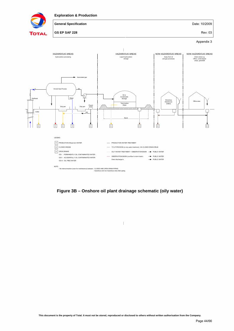
Exploration & Production
General Specification Date: 10/2009
GS EP SAF 228 Rev: 03
Appendix 3
This document is the property of Total. It must not be stored, reproduced or disclosed to others without written authorisation from the Company.
Page 44/66
Figure 3B – Onshore oil plant drainage schematic (oily water)
OD III
Office areaWorkshop
WarehouseUtilities
OD II
Oil orCondensate
Storage
OD I
Tank bottomWater
OD II
Oil and Gas Process
Associated gas
Oil
Water
PWOD ICDOD I
Drip pan
Cellar
Drip panPaved
OD II
OR
PRODUCTION (Reservoir) WATER
CLOSED DRAINS
OPEN DRAINS
OD I : PERMANENTLY OIL CONTAMINATED WATER
OD II : ACCIDENTALLY OIL CONTAMINATED WATER
OD III : OIL FREE WATER
PW
CD
OD
PRODUCTION WATER TREATMENT
TO LP PROCESS (or oily water treatment), VIA CLOSED DRAIN DRUM
OILY WATER TREATMENT + OBSERVATION BASIN
OBSERVATION BASIN (overflow to storm basin)
Direct discharge to
PUBLIC WATER
PUBLIC WATER
- No interconnection (even for maintenance) between : CLOSED AND OPEN DRAIN PIPING: hazardous and non hazardous area drain piping
Bund
areas
HAZARDOUS AREASHydrocarbon processing
HAZARDOUS AREASLiquid hydrocarbon
storage
NON HAZARDOUS AREASAway from oil
and gas processes
NON HAZARDOUS AREASClean areas e.g.
Office, undevelopedareas, greenbelt
Wellhead
PUBLIC WATER
NOTE :
LEGEND :

Exploration & Production
General Specification Date: 10/2009
GS EP SAF 228 Rev: 03
Appendix 3
This document is the property of Total. It must not be stored, reproduced or disclosed to others without written authorisation from the Company.
Page 45/66
Figure 3C – Offshore platform drains schematic

Exploration & Production
General Specification Date: 10/2009
GS EP SAF 228 Rev: 03
Appendix 3
This document is the property of Total. It must not be stored, reproduced or disclosed to others without written authorisation from the Company.
Page 46/66
Figure 3D – Offshore minimum installation drains schematic
CLOSED DRAINS SLOPE
MAINDECK
DRIP PAN DECK
DRIP PANS SLOPE
TESTSEPARATOR
LP VENT HEADER
LP VENT & CLOSED DRAIN
DRUM
CELLAR DECK
200m
m M
IN
BOAT LANDING
200m
m M
IN
OPEN DRAIN DRUM20
0mm
MIN
BOAT LANDING
200m
m M
IN
VENT TOATMOSPHERE
NOTE 3
OVERFLOW
FLAMEARRESTER
OVERFLOW
BELOWCELLARDECK
CLEAN WATERDRAINS
HAZARDOUS DECKS NON-HAZARDOUS DECKS
VENTS TOATMOSPHERE
2m
SEA
NOTES :
1 - DRAIN HEADER OUTLETS PERMANENTLY SUBMERGED IN WATER.2 - THE SKIMMING PUMP IS OPTIONAL. IF PROVIDED, MINIMUM DIFFERENTIAL HEIGHT BETWEEN HEADER DRAIN OUTLET AND PUMP SUCTION IS 2M.3 - LP VENT & CLOSED DRAIN SYSTEMS TO BE DESIGNED FOR INTERNAL EXPLOSION.
NOTE 1NOTE 2 DISPOSAL
TUBE
FROMDECK DRAINS

Exploration & Production
General Specification Date: 10/2009
GS EP SAF 228 Rev: 03
Appendix 3
This document is the property of Total. It must not be stored, reproduced or disclosed to others without written authorisation from the Company.
Page 47/66
Figure 3E – Process platform drains collection

Exploration & Production
General Specification Date: 10/2009
GS EP SAF 228 Rev: 03
Appendix 3
This document is the property of Total. It must not be stored, reproduced or disclosed to others without written authorisation from the Company.
Page 48/66
Figure 3F – Offshore deck classified open drains collection

Exploration & Production
General Specification Date: 10/2009
GS EP SAF 228 Rev: 03
Appendix 3
This document is the property of Total. It must not be stored, reproduced or disclosed to others without written authorisation from the Company.
Page 49/66
Figure 3G – Offshore sump tank and disposal tube
LEGEND :SC : SAMPLE CONNECTIONSG : SIGHT GLASSMCC : MOTOR CONTROL CENTER
FLAME ARRESTER
LOCAL INSTRUMENT
CENTRAL CONTROL
FROM CLASSIFIED OPEN DRAINS
LAH
LI
LAL
VENT TO ATM
VENT TO ATM
SYPHON BREAKER
200m
m M
IN
LT
NORMAL LIQUID LEVEL
OIL RICH OUTLET
1000
mm
MIN
200m
m M
IN
SUMPTANK
WATER RICH OUTLET
TO CLOSEDDRAIN DRUM
CELLAR DECKCLASSIFIED OPEN DRAINS
UNCLASSIFIED OPEN DRAINS
ROOM INSTRUMENT
FO
SEAWATERPURGE
SC
VENT
INERTGAS
PURGE
DRAINS DISCHARGE
DISPOSAL TUBE
8 m
2 m
EL -15.0m to -30.0m
H
OILY WATER
TIDE GAUGE
EL 0.0m
XLS
ESDSTOPPED
XLARUNNING
HS HS
STOP STARTMCC
SG
TOATM
DISPOSALTUBEPUMP

Exploration & Production
General Specification Date: 10/2009
GS EP SAF 228 Rev: 03
Appendix 3
This document is the property of Total. It must not be stored, reproduced or disclosed to others without written authorisation from the Company.
Page 50/66
Figure 3H – Paved area for high volatility hydrocarbon liquid process plant
GRATING
SUB-CATCHMENT AREA DRAINAGE
NOTES :1 - External impounding basin capacity designed for maximum hydrocarbon liquid spillage.2 - Paved area general slope is 2% minimum.3 - Draining ditch is optional.4 - Rainwater pump may be a mobile unit.
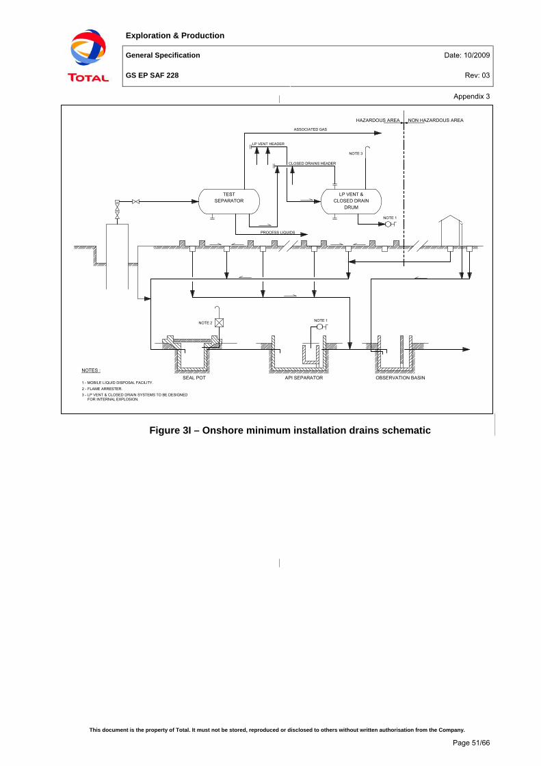
Exploration & Production
General Specification Date: 10/2009
GS EP SAF 228 Rev: 03
Appendix 3
This document is the property of Total. It must not be stored, reproduced or disclosed to others without written authorisation from the Company.
Page 51/66
Figure 3I – Onshore minimum installation drains schematic
NOTE 2 NOTE 1
SEAL POT API SEPARATOR OBSERVATION BASIN
TESTSEPARATOR
LP VENT &CLOSED DRAIN
DRUM
NOTE 3
LP VENT HEADER
CLOSED DRAINS HEADER
NOTE 1
PROCESS LIQUIDS
ASSOCIATED GAS
HAZARDOUS AREA NON HAZARDOUS AREA
NOTES :
1 - MOBILE LIQUID DISPOSAL FACILITY.2 - FLAME ARRESTER.3 - LP VENT & CLOSED DRAIN SYSTEMS TO BE DESIGNED FOR INTERNAL EXPLOSION.
Exploration & Production
General Specification Date: 10/2009
GS EP SAF 228 Rev: 03
Appendix 4
This document is the property of Total. It must not be stored, reproduced or disclosed to others without written authorisation from the Company.
Page 52/66
Appendix 4 The collection of the drainage effluent in onshore process and utility areas (prescriptive)
This Appendix is a part of the chapter 7 (see section 7.4).
Drain collection points There are two main types of collection points for effluent entering the drain system:
• Tundishes
• Gullies. Tundishes (see Figure 4B) are basically open pipe connections that collect drips from “equipment drains”: hydrocarbon pump glands and bearings, sample draw-off points, instrument drains and generally all point-type sources of oily drips and spillage. The lip of the tundishes should be located 50 mm minimum above ground level to prevent flooding of the oily water drain systems with rain/fire water.
Gullies (see Figure 4B) are open devices used as a single point to collect surface drainage. Their size and shape depends on the volumes of effluents which have to be collected; gullies designed to collect large flows of fire and/or rainwater are referred to as catch basins (see Figures 4B and 4C).
Gullies collecting oily water shall be designed so as to contain a permanent layer of water.
Manholes (see Figure 4C) are access points to a drain header. They also act as junction boxes between drain headers. They shall be normally enclosed and in most cases buried.
Equipment drip pans (OD1 and OD2) Figure 4A of this Appendix shows the typical layout of an oil/condensate processing plant collection system.
Refer to the section 4.3.3, which states the requirement for drip pans under process and utility equipment. One drip pan should be dedicated to only one item of equipment. Only small, closely grouped independent items handling compatible fluids (e.g. very small pumps) may share the same drip pan.
The equipment drip pans shall be permanently connected to the appropriate oily water drains via tundishes and/or gullies:
• Equipment processing hydrocarbon liquids: connection to OD1 drains
• Equipment not handling hydrocarbon liquids: connection to OD2 drains (e.g. engines, tools, utility pumps and compressors).
Such drip pans are not to be confused with the bunded areas installed around the hydrocarbon liquid storage facilities, designed for the containment of a major accidental spillage and connected to the open drains via a normally closed valve.
The equipment delivered in skids shall be provided with drip pan in factory, the drip pan being connected to the installation open drains during on-site installation.
The kerbs and plates (or truncated pipes) used around the perimeter of the drip pans shall be no less than 100 mm high.
One given drip pan shall cover at least the ground plan of the item of equipment it serves. Further allowance for collection of drips and minor spillage shall be decided on a case by case

Exploration & Production
General Specification Date: 10/2009
GS EP SAF 228 Rev: 03
Appendix 4
This document is the property of Total. It must not be stored, reproduced or disclosed to others without written authorisation from the Company.
Page 53/66
basis, depending on the type of equipment and associated operations. Ideally any leakage of liquids from one facility should not be directed under any other facility before reaching a drainage system.
All items within the drip pan which are point-type sources of oily drips during routine operation should be pointing directly to a tundish, or should be piped to above a gully located within the drip pan.
As far as practicable, each drain intake within a drip pan shall be connected directly to a manhole, sealed on entry by submerging the inlet pipe a minimum of 300 mm below the water level in the manhole (see Figure 4C). The distance between a tundish/gully and its manhole should not exceed 15 metres.
Closely grouped drip pans or catchment basins may be connected to the same header when individual connection to a manhole is not practical.
For effective surface drainage of drip pans, those shall be sloped at a gradient no less than 1% to a gully located as far as practicable from the sources of pollution within the drip pan.
Figure 4D of this Appendix shows the configuration of a pig receiver drip pan for liquid hydrocarbon pipelines.
Paved areas: general requirements Process plants handling hydrocarbon liquids shall be paved to avoid infiltration of hydrocarbons into the soil. All areas within a minimum of 1.5 meter from the kerb or drip pan of a hydrocarbon process facility shall be paved (see Figure 4A). Paved areas shall be surrounded by a continuous kerb of minimum 150mm height, for containment of accidental spillage, in accordance with section 4.10.
Beyond this, the extent of paving shall be strictly limited to the collection of oily water to prevent the unnecessary collection of clean rainwater. Paths between process units may be gravelled to allow percolation of clean water into the soil.
As far as practicable, OD1 and OD2 drains from different fire zones (see definition in GS EP SAF 253) should not be collected in the same headers: drains from process paved areas and hydrocarbon storage areas, drains from independent process trains, drains from process paved areas and furnaces should be collected separately.
Paved areas: lay-out and drainage Refer to Figure 4A of this Appendix which shows the typical layout of an oil/condensate processing plant collection system.
Plants are divided into paved areas which then should be sub-divided into smaller sub-catchment areas arranged so as:
• To handle the rain/fire water design flows
• To prevent flooding
• To prevent the spread of fire and flammable liquids from one sub-catchment area to another
Paving shall be sloped to the nearest gully at a gradient of not less than 1%. The maximum slope shall be 4%.
Outside the equipment drip pans, gullies in paved areas collect primarily rainwater and firewater: they are referred to as “catch basins” in this specification. They shall be capable of draining the design flows without flooding of their sub-catchment area occurring.
Exploration & Production
General Specification Date: 10/2009
GS EP SAF 228 Rev: 03
Appendix 4
This document is the property of Total. It must not be stored, reproduced or disclosed to others without written authorisation from the Company.
Page 54/66
Catch basins are recessed into the paving. Grating (flush with the paving surface) shall cover them and allow easy removal.
Each catch basin should normally be connected directly and sealed into a manhole. Where this is not practical, it shall be sealed with a dip pipe into the next catch basin: the minimum seal depth shall be 300 mm (see Figure 4C). In paved areas, there should not be more than three catch basins in series.
In areas where water run-off is likely to carry sediments, sand or other solids prone to silt, gullies and catch basins shall be fitted with sediment/sand traps.
Catch basins should have adequate provision for rodding of the drainage underground pipes.
The maximum drainage area for one catch basin shall be 400 m2.
The flow accommodated by one gully/catch basin should not exceed 120 m3/h. The maximum travel of liquid to a gully/catch basin should be 20 meters.
Paved areas shall be designed so that liquids do not accumulate beneath the pipeways. Gullies and catch basins shall not be located beneath process equipment or pipeways. They shall not be located closer than 10 m to fired heaters or other permanent ignition source. They shall not be made of plastic.
Manholes Manhole typicals are shown in Figure 4C in this Appendix.
In addition to the construction (structural) requirements, manholes shall be provided in sufficient numbers to properly seal and vent the drainage underground pipes.
Manholes should be provided and located as required in GS EP CIV 202:
• Every 70 m of drainage pipe of 24” diameter and less
• Every 100 m of drainage pipe greater than 24” diameter
• At each junction point between sub and main headers
• At each point where there is a change in header diameter, direction or elevation (depth).
All manholes carrying effluents containing flammable gases or liquids shall be vented and sealed with water on entry, with a 300 mm depth as a minimum.
The seal should generally be achieved by installing dip pipes in water. For very large drain pipes (16” diameter and above) or manholes with two or more inlets, manholes should be fire sealed by an isolation baffle (split manhole with two vents).
The only exceptions to the requirement for entry seals are: manholes that are necessary only for a change in pipe direction or structural reasons, and with no additional influent pipes connected. There shall be however a sealed manhole at least every 300 m of main drainage header.

Exploration & Production
General Specification Date: 10/2009
GS EP SAF 228 Rev: 03
Appendix 4
This document is the property of Total. It must not be stored, reproduced or disclosed to others without written authorisation from the Company.
Page 55/66
Venting shall be to a local vent, or to a process vent system designed for venting atmospheric capacities. The manhole vent discharge point shall be located at least 3 m above ground and the following minimum safety distances shall apply:
• Distance to building window or air intake: 5 m
• Distance to the edge of a roadway in plant restricted area: 5 m
• Distance to a permanent source of ignition: 15 m
• Distance to combustion chamber air intake: 15 m
• Distance to a public road: 30 m
The vent diameter shall be 3” or 4” (upper limit is to prevent gas accumulations, install two vents if necessary).
Manholes are usually made of concrete. They shall be waterproof and adequately protected externally and internally (e.g. by lining against corrosion, chemicals).
Manholes shall be closed with covers removable for routine inspection. An appropriate sealant shall be used to prevent gas leaks from the manholes located:
• In or adjacent to potential sources of ignition in areas classified non-hazardous, or
• Near roadways.
For manholes intended to be used as an access point for internal inspection of the drainage network, the size of the cover shall be:
• Minimum diameter: 600 mm for circular covers
• No side less than 500 mm for rectangular covers.
They shall be sized such as to prevent overflowing and overpressures. The following minimum sizes shall apply:
• Diameter/side: 1 meter
• Outlet pipe diameter: 6” (8” for the last manhole upstream an oil trap or primary treatment unit).
Important note : The drawings and figures contained in this specification are illustrative only and should not be regarded as detailed engineering documents. They illustrate some of the points made in the specification and should be used as a basis for the preparation of detailed engineering drawings.

Exploration & Production
General Specification Date: 10/2009
GS EP SAF 228 Rev: 03
Appendix 4
This document is the property of Total. It must not be stored, reproduced or disclosed to others without written authorisation from the Company.
Page 56/66
Figure 4A – Onshore oil plant paved areas

Exploration & Production
General Specification Date: 10/2009
GS EP SAF 228 Rev: 03
Appendix 4
This document is the property of Total. It must not be stored, reproduced or disclosed to others without written authorisation from the Company.
Page 57/66
Figure 4B – Onshore open drain ancillary equipment
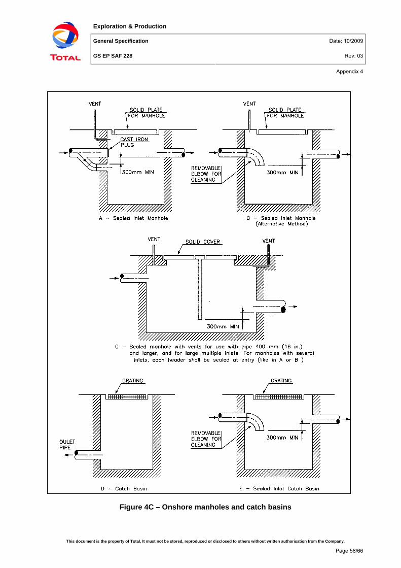
Exploration & Production
General Specification Date: 10/2009
GS EP SAF 228 Rev: 03
Appendix 4
This document is the property of Total. It must not be stored, reproduced or disclosed to others without written authorisation from the Company.
Page 58/66
Figure 4C – Onshore manholes and catch basins

Exploration & Production
General Specification Date: 10/2009
GS EP SAF 228 Rev: 03
Appendix 4
This document is the property of Total. It must not be stored, reproduced or disclosed to others without written authorisation from the Company.
Page 59/66
Figure 4D (1) – Pig receiver drainage (onshore and offshore)

Exploration & Production
General Specification Date: 10/2009
GS EP SAF 228 Rev: 03
Appendix 5
This document is the property of Total. It must not be stored, reproduced or disclosed to others without written authorisation from the Company.
Page 60/66
Appendix 5 The collection of the drainage effluent in offshore process and utility areas (prescriptive)
This Appendix is a part of the chapter 8 (see section 8.2).
This Appendix assumes that the offshore installation is fixed. For F(P)SO, the detail design may be slightly different to make up for vessel movement.
Drain collection points Appendix 5, Figures 5A, 5B and 5C illustrate the points made in this section.
There are two main types of collection points for effluent entering the drain system:
• Tundishes
• Gullies.
Onshore tundishes have been described in Appendix 4, offshore tundishes serve the same function.
Gullies are open devices used as a single point to collect surface drainage, either on deck or in drip pans. Their size and shape depend on the volumes of effluents, which have to be collected. Gullies for rainwater collection are channels recessed into the deck. All gullies shall be covered by grating at deck level. Gratings shall be arranged for easy removal and fitted such as to prevent trip hazards.
The gullies of the classified and unclassified open drains shall be designed so as to contain a permanent layer of water. They should be made short to minimise the risk of spread of fire due to flammable liquids and vapours in the channel; they should typically be 1.5 meter long. There should be at least 3 gullies per 100 m2 of deck surface.
Overloading of gullies in open drainage shall be catered for by provision of freeboard above the design flow level. This freeboard should not be less than 100 mm. For gullies provided with firewater overflows, the freeboard shall be between the design flow level and the lip of overflow tundish level.
Gullies shall be designed to slope towards the open drain pipe intake, with a 2% minimum slope. Use of weirs in gullies should be avoided.
Presence of sand or other solids prone to silt shall call for purposely designed sand/sediment traps in gullies (e.g. removable strainers).
Drip pans Drip catchment areas underneath offshore equipment are commonly called drip pans or drip trays. They are generally referred to as drip pans for offshore installations.
Offshore equipment drip pans follow the same design, installation and operation rules as detailed in Appendix 4 and in section 4.3.3. Drip pan specificities for offshore installations are given below. Provisions for accidental spillage, outside of the drip pan, should be implemented in accordance with requirements given in section 4.10.
Equipment drip pans shall be permanently connected to the appropriate oily water drains via tundishes and gullies:
• In hazardous areas: connection to the classified drains
• In non-hazardous areas: connection to the unclassified drains.
Exploration & Production
General Specification Date: 10/2009
GS EP SAF 228 Rev: 03
Appendix 5
This document is the property of Total. It must not be stored, reproduced or disclosed to others without written authorisation from the Company.
Page 61/66
Drip pans shall be designed to slope towards a gully, with a 2% minimum slope.
Classified open drains Every gully and tundish shall be collected independently to a sub-header. Piping from every such item shall incorporate a siphon of 300 mm minimum seal depth.
There shall be at least one horizontal sub-header per module or per deck level, connecting and sealing into a classified open drains main vertical header running directly into the sump tank.
Seal pots (see Figure 5D) shall be used in preference to piping siphons to seal a drain sub-header to the vertical main header. The seal pots should have a seal depth at least twice the seal depth of the siphons provided at drainage intake points. The seal depth shall be no less than 600 mm. The diameter of the seal pot should be no less than 5 times the diameter of the inlet drain sub-header.
Seal pots shall be connected to vents or vent headers so that trapped gas is safely vented and pressure fluctuations in one drainage sub-header cannot adversely affect another sub-header (the recommended diameter of an individual vent is 2”). Vent outlets shall be diverted away from sources of ignition (refer to GS EP SAF 216).
Under abnormal conditions of firewater surge flow, drainage shall be diverted away from the classified open drain headers. This shall be achieved by incorporating two offtakes in gullies (see Figure 5A).
Provided that firewater/rainwater surge flows are not taken by the classified open drains, the classified open drains system shall be sized based on:
• The washdown case (refer to section 6.2.) or as far as practicable
• The accidental spillage case (refer to section 8.5.3)
Unclassified open drains Every gully and tundish shall be collected independently to the horizontal sub-header. Piping from tundishes and gullies should incorporate a siphon (seal depth of 50 to 300 mm depending on service).
There should be at least one sub-header per deck level. Each horizontal sub-header is connected to a main vertical header running directly into the oily water disposal tube, where it is submerged permanently below the caisson liquid level.
The unclassified open drains pipes are usually sized based on the washdown case (refer to section 6.2. (“design flows”)). Rainwater is normally not dimensioning i.e. units draining into the unclassified open drains are not deluged and are usually roofed.
Clean water drains This is a piped drain system collecting oil-free water from gullies to headers leading to an outboard discharge point located below the cellar deck.
The clean water drain headers shall also accommodate all firewater/rainwater overflows from the hazardous areas. The greater of the firewater and rainwater cases shall be selected for the sizing of this system (they shall not be added, refer to section 6.2.. (“design flows”)).
All drainage outfalls to sea shall be located so that the platform seawater pump intakes, particularly those feeding the potable water maker if any, are at maximum distance and across normal tidal current direction.

Exploration & Production
General Specification Date: 10/2009
GS EP SAF 228 Rev: 03
Appendix 5
This document is the property of Total. It must not be stored, reproduced or disclosed to others without written authorisation from the Company.
Page 62/66
Exceptions to the rules set out in this section:
• Single deck platforms (such as in river deltas): discharge of excess rainwater/firewater overboard to sea or river is acceptable
• Multi-deck platforms: if on a deck very large rainwater (not firewater) flows associated with severe, rare storms resulted in the need for very large diameter lines, routing of this run-off water over the deck plates and discharge overboard could be considered. Overflow points at the edge of the platform shall be identified and the consequence of the potential carry-over of oil to the lower deck assessed. All overboard discharges shall be kept away from equipment, personnel, escape routes and lifeboats on lower decks. Such design requires derogation to this specification, duly approved by COMPANY.
Important note : The drawings and figures contained in this specification are illustrative only and should not be regarded as detailed engineering documents. They illustrate some of the points made in the specification and should be used as a basis for the preparation of detailed engineering drawings.

Exploration & Production
General Specification Date: 10/2009
GS EP SAF 228 Rev: 03
Appendix 5
This document is the property of Total. It must not be stored, reproduced or disclosed to others without written authorisation from the Company.
Page 63/66
Figure 5A – Offshore open drain ancillary equipment

Exploration & Production
General Specification Date: 10/2009
GS EP SAF 228 Rev: 03
Appendix 5
This document is the property of Total. It must not be stored, reproduced or disclosed to others without written authorisation from the Company.
Page 64/66
Figure 5B – Offshore platform rainwater collection (1)

Exploration & Production
General Specification Date: 10/2009
GS EP SAF 228 Rev: 03
Appendix 5
This document is the property of Total. It must not be stored, reproduced or disclosed to others without written authorisation from the Company.
Page 65/66
Figure 5C – Offshore platform rainwater collection (2)
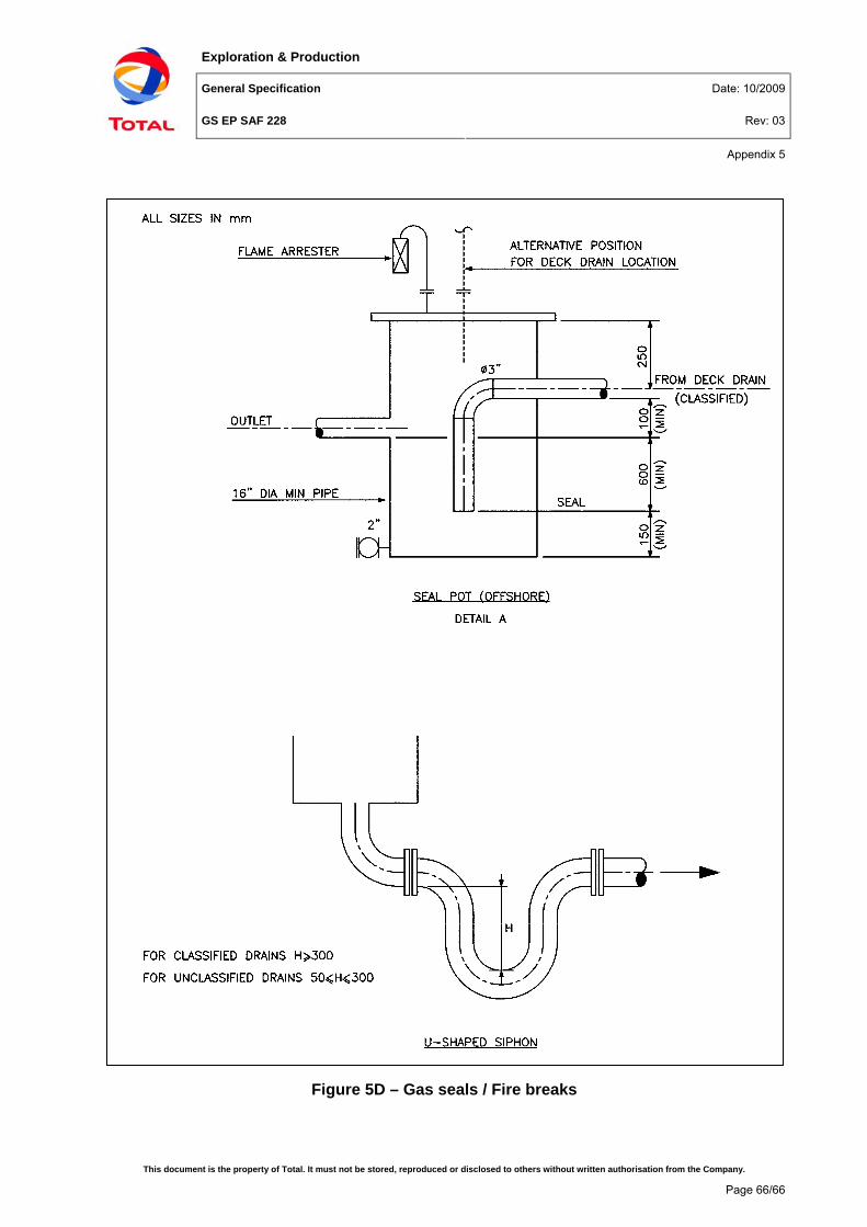
Exploration & Production
General Specification Date: 10/2009
GS EP SAF 228 Rev: 03
Appendix 5
This document is the property of Total. It must not be stored, reproduced or disclosed to others without written authorisation from the Company.
Page 66/66
Figure 5D – Gas seals / Fire breaks