GS-232B -
24
GS-232B Computer Control Interface for Antenna Rotators YAESU COMPU I EM CONTROLLER GS-232B o POWER =1 .0.0 VERTEX STANDARD CO., LTO. 4-8-8 Nakameguro. Meguro·Ku Tokyo 153---8644, Japan VERTEX STANDARO us Headquarters 10900 Walker SHeet. Cypress, CA 90630, USA. YAESU EUROPE B.V. P O. Box 75525. 1118 ZN SChlphol The Netherlands YAESU UK LTO. Unit 12, Sun Valley Business Park, Wmnall Close Winchester, Hampshire. 8023 OLB, U.K. VERTEX STANDARD HK LTD. Unit 5, 20/F., Seaview Centre, 139·141 HOI Bun Road. Kwun Tong Kowloon, Hong Kong
Transcript of GS-232B -

~~YAESU
GS-232BComputer Control Interfacefor Antenna Rotators
YAESUCOMPU I EM CONTROLLER
GS-232B
oPOWER
=1
.0.0
VERTEX STANDARD CO., LTO.4-8-8 Nakameguro. Meguro·Ku Tokyo 153---8644, Japan
VERTEX STANDAROus Headquarters10900 Walker SHeet. Cypress, CA 90630, USA.
YAESU EUROPE B.V.P O. Box 75525. 1118 ZN SChlphol The Netherlands
YAESU UK LTO.Unit 12, Sun Valley Business Park, Wmnall CloseWinchester, Hampshire. 8023 OLB, U.K.
VERTEX STANDARD HK LTD.Unit 5, 20/F., Seaview Centre, 139·141 HOI Bun Road.Kwun Tong Kowloon, Hong Kong

ill ill illFl ... I"l.... ~...- • ____'''f!!!!!: j
L1"- -Ij---:ii I :_ £.11111
0..-.-"----~.£ - :-
ill.-...
H
ill-iliiiiii;;=-.'
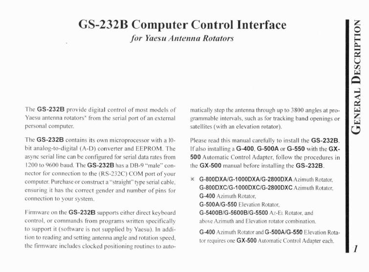
GS-232B Computer Control Interfacefor Yaesu Antenna Rotators
The GS-232B provide digital control of most models ofYaesu antenna rotators" frolll the serial port of an externalpersonal computer.
The GS-2328 contains its O\\ln microprocessor with a tobit analog-to-digital (A-D) converter and EEPROM. Theasync serial line can be configured for serial data rates from1200 to 9600 baud. The GS-232B has a D8-9 "male" connector for connection to the (RS-232 ) COM port of yourcomputer. Purchase or construct a"straight" type serial cable.ensuring it has the correct gender and number of pins for
connection to your system.
Firmware on (he G5-2328 SUppOr1S either direct keyboard
control, or commands frol11 programs written specifically
10 support it (software is not supplied by Yaesu). In addi
lion to reading and setting antenna angle and rotation speed,the firmware includes clocked positioning routines (0 auto-
matically step the antenna through up to 3800 angles at programmable intervals, such as for tracking band openings orsatellites (with an elevation rotator).
Please read this lIlanual carefully to install the GS-232B.Ifalso installing a G-400, G-SOOA or G-SSO with the GX500 Automatic Control Adapter, follow the procedures inthe GX-SOO manual before installing the GS-232B.
x G-800DXA/G-1 000DXAlG-2800DXA Azillluth Rotator.G-800DXC/G-1000DXC/G-2800DXC Azillluth Rotator.G-400 Azimuth Rotator.G-SOOA/G·SSO Elelation Rotator.G-S400B/G-S600B/G-SSOO A7-El Rotator. andahmc A/imuth and Elc\ation rotator combination.
G-400 Azimuth Rotator and G-SOOA/G-SSO Ele\ ation Rotator requires olle GX-500 Automatic Control Adapter each.
1

enZo-~u-...-ULolC
OO
2
GE ERAL
Po\\cr Requirements: DC 12 V. 70 mACase Size: 4.3" (W) x 0.8'" (H), 5.4" (D)
(110x21 x 138 mill)Weight (approx.): 13.4 oz. (380 g)
SemiconductorsM ieroproeessor: PIC 18C452
(includes 10 bits AD eomener)EEPROM: 24LC256Serial Comms: RS-232C voltage le\'els.
1200 to 9600 baud, 8 data bits,1 stop bit, no parity
Overnow ConI.: Hardware Control (CTS pan)
CONNECTOR PINOUT
Serial I/O:9-pin DB-9 connector (RS-232C connector)
Pin 2 - 1 x DataPin 3 - Rx DataPin 5 - Signal GroundPin 7 - Rl SPin 8 - T
Rotator Control:5-pin connector (El connector)
Pin I - UP switch (open collector)Pin 2 - DOW switch (open collector)Pin 3 - analog output (0.5 - 4.5 V. four steps)Pin 4 - analog input (0-5V elevation)
Pin 5 - analog ground5-pin connector (AZ. connector)
Pin 1 - RIGHT s"itch (open collector)Pin 2 - LEFT switch (open collector)Pin 3 - analog output (0.5 - 4.5 V. four steps)Pin 4 - analog input (0-5V azimuth)Pin 5 - analog ground

SUPPLIED ACCE SORIES
o Control cable for the Azimulh Rotator X1 I pc("'5-pil1" - "Mill-DIN" cablc)
o Control cable for the AziEL Rotatorx:! _ I pc("'DlIal 5-pil1" - "DIN" cable)
o DC cable w/coaxial plug I pco llook & loop fasteners (for mounting) I pc
x I: G-800DXA. G-1000DXA. G-2800DXA,G-800DXC, G-1000DXC, al1d G-2800DXC
X2: G-5400B, G-5600B, and G-5500
AVAILABLE OPTIONS
GX-500 COl1trol Adaplcr(Check wilh YOllr dealer)
C-1000 COl1l1ecliol1 Cable(for SOX series Azuirnuth Rotator)
NC-72B/C/F/U" AC Adapierx3: "B" suffix is for use wilh 117 VAC,
"C" suffix is for lise with 220-240 VAC,"F" suJJix is for lise willl 220 VAC, or"U" suffix is for use with 230 VAC
3

During installation. a personal computer \\ilh a serial POfl
and terminal software is required to calibrate trimmers onthe COlltroller and on the Control Intcrf..,cc. An) simple interactive terminal program can be used - it anI) has to trans
mit keystrokes as lyped, and display characters received fromthe GS-232B.
POWER & CONTROL CONNECTIONS
DXA 01' DXC Series Azimuth Rotatoro Connect Ihe supplied DC cable 10 a source of 12 VDC.
The red lead connccts 10 the Posilive (+) DC terminal.
and the black lead conneCls 10 the egalive
(-) DC terminal. The GS-232B requires 70 mAo The
supplied cable has a SOO-mA fasl-blow fuse. Use onlythe same Iype fuse for replacemenl.
o Plug the coaxial power connector into the DC 12V jackon Ihe GS-232B rear panel.
o Connect the supplied Control cable ("S-pin" - "Mini,
DIN") belween the EXT CONTROL connector on Ihe
rOlalor's controller and AZ connector all the renr panelof the GS-232B (Figure I) .
4
•• ij "5• ..•0 [..>:! ..~ ~l?- I?-
~
~Figure 1
OXA or DXC series';' Azimuth Rotator
6 0:> o 00 0 0
~r .! ~"'i'!.-: ~~ .",.- -~l·
10
ii3qf-.-- [[5r

I)OWER & CONTIWL CONNECTIONS
5
Figure 3j GX·500
",l,tlE'.~mi~~fiT To EI..... lIlion( ..•.•.. Controll.,
G-tOO/G-SOO or G-tOO/G-550 & air of GX-SOOConnect Ihe supphed DC cable 10 a source of 12 VDC.The red lead connects to the Positi\e (+) DC temtinal,and the black lead connects to the Negative( ) D lerminal. The GS-232B requires 70 mAo Thesupplied cable has a SOO-mA fasl-blow fuse. Use onlythe same t) pc fuse for replacement.Plug the coaxial poll' er connector into the DC 12Vjac~
on the GS·232B rear panel.Connect the S-pin to S-pin cable (supplied \\ith Ihe GX·500; req""es 1"0 sets) belween the GX-500(s) and GS232B (Figure 3).
Figure 2
G-S"OOB/-S600B Az-El. RotatorConnect the supplied DC cable to a source of 12 VDC.The red lead connects to Ihe Positive (+) DC lenninal.and the blach lead connects to the \Jegalivc
( ) DC terminal. The GS-232B requires 70 mA. 1 hesupplied cable has a SOO-mA fast-blow fu e. Use onl)the same t) pc fuse for replacement.Plug the coaxial po\\er connector into the DC 12V jackon the GS-232B rear panel.Connect the supplied Control cable ("Dual S-pin" "DI ") bel\\een Ihe rotator's comroller and GS-232B.Be careful to malch the "AZ." and '"EL" labels on Ihe cableII' ilh the same labels on the rear panel oflhe GS-232B(Figure 2).

POWER & CONTROL CONNECTIONS
SDX Series Azimuth Rotatoro Prepare Ihe optional C-1000 Connection Cable.
Remme the Top Cover from the controller.
o Connect the 8-pin connector orthe C-1000 Connectioncable to the exposed 8-pin connector located the rearleft corner in the controlk:r.
o Route the 5-pin connector or the C-1000 ollnectioncable through Qut the rubber grommet on the rear panelof the controller. and connect illO the AZ. connector 011
the rear panel of the GS-232B (Figure 4).o Replace the fop Cmer.
ConnCCllhe supplied DC cable to a source of 12 VDC.The red lead connects to the Positive (+) DC terminal.
and the blac" lead connects 10 the cgati\c( ) DC terminal The GS-232B requires 70 mAo 1 he
;upplied cable has a 500-mA fast-blo\\ fllse. Usc onl)
the sal1l~ ')epe fuse for replacement.o Plug theconxial po\\ereOnneclOr into the DC 12V jac~
on the GS-232B rear panel.
Optional C-1000 Connection CableOutput GrOmmtl ,~C·1OOO Conn.cllon C.ble
Figure 4
ellposed a_pin Confle<:tOfl~de of I~ Conlroller)
SOX seriesAzimuth Rotator
6
COMPUTER CONNECTION
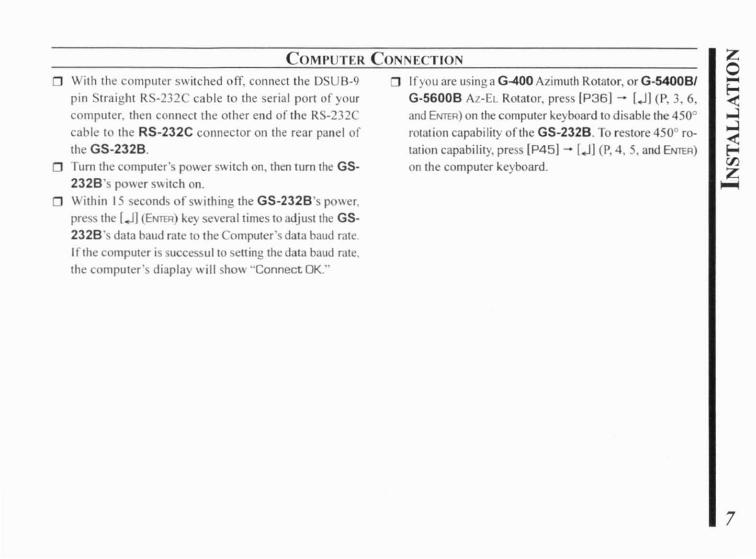
With the compuler swilched off, connect lhe DSUB-9
pin Straighl R -232C cable 10 lhe serial P0rl of your
computer. lhen connect the olher end of lhe R -232Ccable to the RS-232C connector on the rear panel of
lhe GS-232B.
o Tum the computer's power switch on, then tum the GS232B's pOller swilCh on.
Within 15 seconds ofs\\ilhing lhe GS-232B's po"er.
press the IJl (Ef>lT"ER) key several times to adjuslthe GS232B's data baud rate to the Computers data baud rate
Irthe computer is su ccs~lIl to selling the data baud rate.the computer's diaplay will hO\\ "Connect OK:'
Ifyou are using a G-400Azimuth ROlator, orG-5400BI
G-5600B AL-EL Rotator, press IP361 - [Jl (P, 3, 6,and Ef>lT"ER) on the eomputer keyboard to disable the 4500
rOlation eapabilily of the GS-232B. To reslore 4500 ro
lalion eapability, press IP45) - [Jl (P, 4, 5. and Ef>IT"ER)on lhe eomputer keyboard.
7
DXNDXC/SDX SERIES AZIM TIl ROTATORzo-~Cl:l
~U
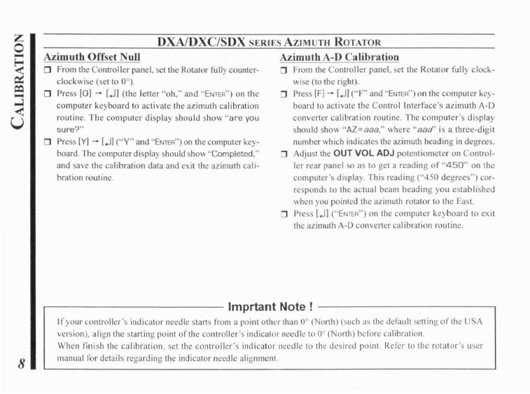
Azimuth Offset ullo From the Controller panel. sel lhe Rotator fully counter
clock\\ ise (sella 0 ).
o Pres [0] - [.1l (Ihe letter "oh.'· and "ENTER') on Ihe
computer keyboard 10 activate the azimuth calibrationroutine. The computer display should show "are yousure?"
Press IYI - [.11 (',y" and "ENTER') on Ihe computer "ej·board. 1 he compulerdisplay should sho\\ "Completed."
and sa\e the calibration data and exit the azimuth calibration routine.
Azimuth A-D Calibration:J From the Controller panel. el the ROlalor fully c1ock
\\ ise (10 lhe righl).:J Press [F] - l.1l ("F" and "ENTER") onlhe computer ke)
board to activate the Control Interface's azimuth A-Dconverter calibration rOlltine. The computer's displayshould show "AZ=S80:' where "88B" is a three-digitnumber which indicates the azimuth heading in degrees.
:J Adjust lhe OUT VOL ADJ potenliomeler on onlrol
ler rear panel so as to gel a reading of "450" on thecomputer's displa). This reading ("450 degrees") corresponds to the actual beam heading you established\\hen )Oll pointed the azimuth rotator to the East.
:J Press l.1l ("ENTER") on lhe compuler keyboard to exitthe azimuth A-D convcr1cr calibration routine.
8
Imprtant Note!If)our controller's indicator needle start') from a point other than 0 ( 011h) (such <Iii the defaLlh setting of the USAversion). align the slarting point of the controller's indicator needle 100 (North) before calibration.When finish the calibration, set the controller's indicator needle to the desired point. Refer to lhc rotator's u\crmanual for details regarding the indicator needle alignment

G-400 AZIMUTI-I ROTATOR
Azimuth Offset Nullo From the Controller panel. sct lhe Rotator fully countcr
clock\\ ise (get to 0°).
o Press [0] - [..II (I he letler "oh:' and "ENTER") on thecomputer keyboard to activate the azimuth calibrationroutine. The computer display shollid show "are yousure?"
o Press [Vj - f.J] ("V" and "ENTER") on the computer keyboard. The computer displa, should show ''Completed:'and save (he calibration data and exit the azimuth calibration routine.
Azimuth A-D Calibrationo From the Controller panel. set the Rotator fully clock
wise (to the right).o Press [FJ - [..I] ("F" and "ENTER") on the computer key
board to activate the Control Interface's azimuth A-Dconverter calibration rOlltine. The computer's displayshould show "AZ=aaa." where "088" is a three-digitnumber which indicates the azimuth heading in degrees.
o Adjust the FULL SCALE ADJ on the GX-500 so as togel a reading of"180" on the computer's display. Thisreading ("180 degrees") corTcsponds to the actual beamht:ading )Oll eSlablished when yOll pointcd the azimuthrolator (0 the Soulh (the fully clockwise seuing).Press [JI ("ENTER") on the computer keyboard to exitthe azimuth A-I) convener calibration routine.
9
G-5400B/-5600B Az-EL ROTATORzo-~CQ-...J<U
10
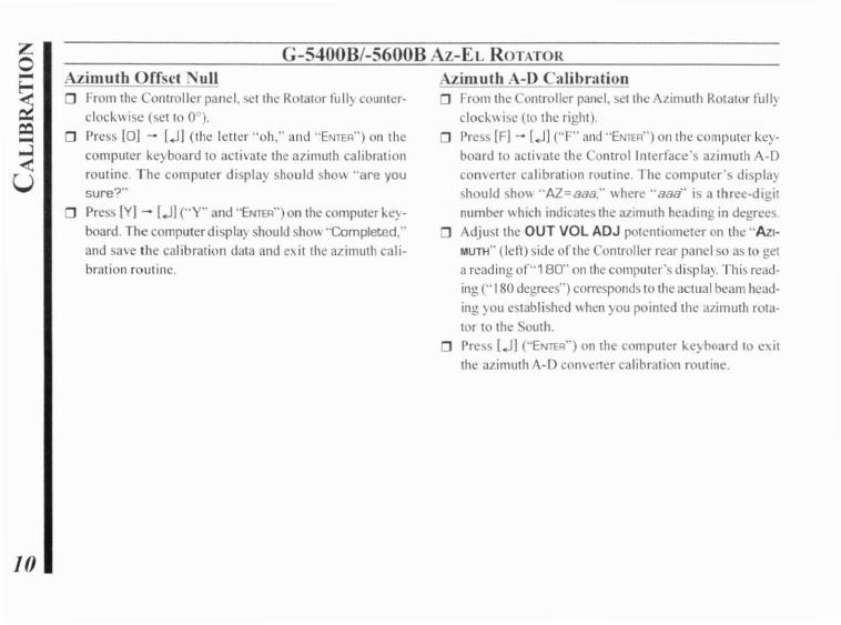
Azimuth Offset ~ull
o From the Controller panel, set the Rotator full) counterclockwise (set to 0°).
D Press [OJ - l.JJ (the leller "oh:' and "ENTER") on thecomputer "cyboard to activate the azimuth calibrationroutine. The cam pUler display should sho\\ "are yousure?"
D Press [V] - [.JJ ("'Y" and "ENTER") on the computer ke}board. The computerdispla) should show "Completed:'and save the calibration data and c\it the azimuth calibration routine.
Azimuth A-D Calibrationo From the Controller panel, set the AL.il11uth ROlator full)
c1ocl, \\ ise (to the right).
Press [F] - l.JJ ("F" and "ENTER") on the cornputer keyboard to activate the Control Interface's a7imuth A-Dcon\crter calibration routine. The computer's displa)should sho'\- "AZ=ooa:' \\here "oaa" is a three-digitnumber \\ hich indicates the azimuth heading in degrees.
D Adjust the OUT VOL ADJ potentiometer on the "AztMUTH" (leO) side of the Controller rear panel so as to geta reading or"180" olllhe computer's displa~. This read·ing ("180 degrees") corresponds to the actual beam heading) au established \\hen )OU pointed the a7imuth rotator to the outll.
D Press [.JJ ("ENTER") on the computer ~e} board to e,itthe alillluth A-D comerter calibration routine.
G-S400B/-S600B Az-EL ROTATOR
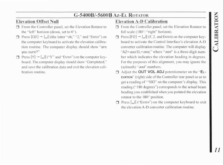
Elevation Offset NullFrom the Controller panel. set the L1cvation Rotator tothe "Ien-' horizon (do\\n. set to 0 ).
o Press [021 - [JI (Ihe leiter "oh:' "2:' and "ENTER") onthe computer keyboard to activate the elevation calibration routine. The computer display should show "areyou sure?"
o Press [Y]- [JI (..y" and "ENTER") on the computer ~e)
board. The computerdispla) should sho\\ "Completed:'and sme lhe calibration data and e\it the ele\ation calibration rOluine.
Elevation A-D Calibrationo From the Controller panel. set the Elc\ation Rotator to
full scale (180 : "right" horizon).o Press [F2j - [JJ (F. 2. and ENTER) on the computer key
board to activate the Control Interface's elevation A-Dconverter calibration routine. The computer will display"AZ=888EL=eee," where "eee" is a three-digit number \\ hich indicates the elevation heading in degrees.For the purposes Oflhis alignment, you may ignore the(azimuth) "88a" numbers.Adjust the OUT VOL ADJ potentiometer on the "ElEVATION" (right) side of the Controller rear panel so as toget a reading 0["180" on the computer's display. Thisreading ("180 degrees") corresponds to the actual beamheading you established when you pointed the elevationrotator 10 the 1800 position.
o Press [JI ("'ENTER") on the computer keyboard 10 exitthe elevation A-D converter calibration routine.
;zo-~Cl:i-....:l<
U
lJ

C-5500 Az-EL ROTATORzo-~Cl:i-.....:l<t:
U
12
Azimuth Offset lullo From the Controller panel. set the Rotator full) counter
clockwise (se, '0 0°).Press 101 - l.J] ('he letter ··oh." and "EmER") on 'hecomputer keyboard to activate the azimuth calibrationroutine. The computer display ShOlIId show "are yousure?"
o Press Iy] - IJI (Hy" and "EmER") on 'he compUler keyboard. The computerdispla)' should sholV "Completed,"and save the calibration data and exit the azimuth calibration routine.
Azimuth A-D Calibrationo From the Controller panel. sel the Azimuth Rotator fully
clockwise (to the right).o Press IF] - 1..11 (F and ENTER) on 'he computer ke)
board 10 activate the Control Interface's azimuth A-Dconverter calibration rOlltine. The computer's displayshould show "AZ=aBB," \\herc "8Ba" is a three-digitnumber which ind icates the azimuth heading in degrees.
o Adjus, the OUT VOL ADJ potentiometer on the "AZIMUTH" (left) side of the Controller rear panel so as to geta reading of"450" on the computer's display. This reading ("450: 360 degrees + 90 degrees") corresponds tothe actual beam heading you established when youpointed the azimuth rolatar fully clockwise,
o Press 1..11 ("EmER") on the compu,er keyboard '0 exitthe azimuth A-D converter calibration rOlltine.

G-5500 Az-EL ROTATOR
Elevation Offset Nullo Press [02] - [JI (the leiter "oh," "2," and "ENTER") on
the computer keyboard to activate the elevation calibration routine. The computer display should show "areyou sure?"
o Press [YI - lJJ ("Y" and "ENTER") on Ihe compuler key
board. The computer display should show "Completed,"
and save the calibration data and exillhe elevation calibration rOlltine.
Elevation A-D Calibrationo From the Controller panel, set the Elevation Rotator to
full seal (180 : "right" horizon).
o Press [F2] - [JJ (F, 2, and ENlffi) on the computer key
board to activate the Control Interface's elevation A-Dconverter calibration routine. The computer will display"AZ=aaaEL=eee," where."eee" is a three-digit number which indicates the elevation heading in degrees.For the purposes of this alignment, you may ignore the(azimuth)" aaa" numbers.
o Adjust the OUT VOL ADJ potentiometer on the "EL
EVATION" (right) side oflhe Controller rear panel so as 10
gel a reading 0["180" on the computer's display. This
reading ("180 degrees") corresponds to the actual beam
heading you established when you pointed the elevationrDlalor to the 1800 position.
o Press IJI ("ENTER") on the com pUler keyboard 10 exit
the elevation A-D converter calibration routine.
I:
G-SOO ELEVATION ROTATOR
/4
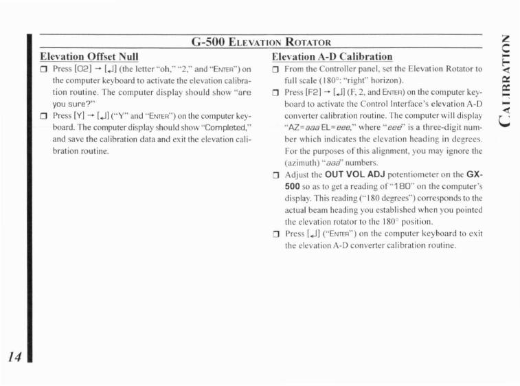
Elcvation Offsct Nulla Press [02] - [-ll (the letter "oh:' "2," and "ENTER") on
the computer kc) board to activate the elC\3tion calibration rOlltine. The computer display should show "areyou sure?"
a Press [YI - [-ll ("Y" and "ENTER") on the computer keyboard. The computer display should show "Completed,"and save Ihe calibration data and exit the elevation cali
bration routine.
Elcvation A-D Calibrationo From the ontroller panel, sct the Elevat ion Rotator to
full scale (180°: "right" horizon).o Press [F2] - [-l] (F, 2, and ENTER) on the computer key
board to activate the Controllnlerfacc's elevation A-D
converter calibration routine. The computer will display
"AZ=888EL=eee," where "eee" is a three-digit nUI11
ber which indicates the elevation heading in degree.
For the purposes of this alignment, you l11a~ ignore the(azimuth) "B88" nLllllbers.
o Adjust the OUT VOL ADJ potentiometer on the GX500 so as to gel a reading of"180" on the computer'sdisplay. This reading ("180 degrees") corresponds 10 theactual beam heading you established when yOll pointed
the elevation rotator to the 1800 position.o Press l-lJ {"ENTER") on the computer keyboard to exit
the elevation A-D converter calibration routine.
zC-!-<l0:a:-
zo
~~0..o
GEIf) Oll \\ ish, you can mOllnt the GS-232B on lap of yourRo!ntor Controller lIsing the 1\\'0 supplied hook-and-Ioopr~sleller strips. Just remove the:: backing from one side ofe<lch strip. and press into place on the bottom of the GS
2328. Then remove the backing frollllhe other side. andpress the GS-232B into place on the Controller.
ERAL
After installation and calibration. the Control Interface canaccept cOl11mands entered directly from the keyboard, orfrom a program writlcn specifically 10 sllpport it (not supplied by Yaesu). For briefslIllllll<lries or the cOll1mands recognized b) Ihe Conlrollnterface, press IHj- [..II for a listofazilllllih commands. or IH2J - [JI for elevations COI11mands. Keep in mind Ihat all cOlllmands require that theENTER key be pressed allerthe command letler (or "DOh"be sent by a control program), although we will not rcpcat(his \\hcn discussing the commands. Also note that any command letter may be sent in either upper or lower casc. Theinfo screcns shown on the next page will be returned by theControl Intcrfacc.
Most cOlllmands have two versions: OIlC for azimuth. andone for elevation. Commands are not echoed by the ControlIllIcrfacc. but a carriage return character ("DOh") is rcturnedoller evel) cOlllllland, and also a line feed e1m,"eler ("OAh")
if the command invoked returned data. Invalid commandscause ..? >" to be relurned and the input buffer cleared. Notethat all angles arc in degrees, beginning with zero at themost cOlllllerclock\\ ilic azimUlh (or hori7ontal elevation).Angles sent to the Control Interface mUsl be 3 digils long(Icn-Iero-padded).
J:

Co 1 lAND LISTzo
~wp..
o
In the follO\\ing cOlllmand dc!)criptlon~. the elevation version or each command. \,here there is one. i hO'\11 in parentheses (but don't t) pc the parentheses). Remember thatelevation commands require the G-5400B. G-5600B orG-5500 AvE I Rotators. or the GX-500 adapter and the G500 or G-550 Elevation Rotator.
0(02)Off\el cnlib,,";o/l for the Azimulh (Elevalion) : preset rOlator manual!) fully counter-c1ock\\ isc ("len" horizon for elevalion), send command, and press [V) - [J] ("Y" and"ENTER") on the computer keyboard to store setting.
H (H2, H3)Returns list of commands (see page 19 and 20).
F (F2)FilII Sc:ale Calih,"titJII: preset rotator manually to full scale.send command. adjust OUT VOL ADJ "immer on rcar ofcontroller (or GX-500 elevalion adapter) until the retumeddata is "+180 or +450" ("+Onn+180" forele\alion). Press[J) ("ENTER") on Ihe compuler keyboard 10 exit the calibmlion routine.
R (U)Start lurning the rotator to the right (up)
Slart turning the rotator to the left (do\\n).
A (E)Stop azimuth (elevation) rotation.
sSlOp: cancel current command before completion.
C(8)Return current azimuth (ele\ation) angle in the form"AZ=aaa" ("EL=eee" for "B" command) degrees.
C2Return azimuth and elevation ("AZ..=888 EL=eee", \\here"888" azimuth." eee" elevation).
P36Switch the azimuth angle to 360 degree mode.
P45Switch the al'imuth angle 10450 degree mode.
zToggle the staning point of the azimuth indicator needlebel\\een" (Nonh)" and "5 (South):'This command is ignored \\hcn the rolalor is set to "450
degree mode."
/6 L (0)
CO 1\1ANI) LIST
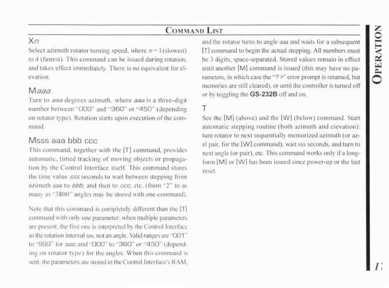
XnSelect azimuth rOlator turning speed. ".here n I (slo\\est)to -I (rastest). This command can be issued during rotation.and lakes effect immediatel). There is no equl\alem ror el·c\ation.
MaaaTurn to 888 degrees iuimuth, where 888 is a three-digitnumber bel\\een "000" and "360" or "450" (dependingon rolatOr t) pc). Rotation starts upon c",cculion orlhe COI11
mand.
Msss aaa bbb eeerhis command. IOgether \\ith Ihe ITl commnnd. providesaUlomatic, timed Irac~ing of moving objecls or propagation b) the Control IlHcrface itselr. This command storesthe time \'alue ssssecond to \\ait bet\\cen '\Iepping fromazimuth aaa to bbb. and then to ccc. etc. (rrom "2" to asman~ as "3800" angles ma~ be storcd \\ itll onc command).
ote Ihat lhis command is complelel) dinerent thalllhc ITIcommand \\ ith onl~ one parameter: \\hen multiple paral11CICI3arc present. the liN onl: jc; inlerpreted b) the ("orllrolllllcrracea~ the rotation interval sss. not all angle. Valid ranges are "001"to "999" lor sss. and "000" to "360" or "450" (depending on rolator type) for the angles. When this command is\t:nt,lllc parameters arc \Iored in the COlllrollnlcrface\ RAM.
and the rotator turns to angle aaa and \\aits ror a subsequentIT] command to begin the actual stepping. All numbers mustbe 3 digits. space-separated. Stored values remain in effeciuntil another 1M) command is issued (Ihis may have no pa·r<lInelers. in \\ hich case the ""? >" error prompt is retumed, butmemories are still cleared). or until the controller is tumed offor b) loggling the GS-232B off and on.
TSee the [M] (above) and the Iwl (belo\\) command. tartaut matic stepping rout inc (both alimuth and eievation):turn rolalor 10 next sequentially memorized azimuth (or azel pair. ror the [wl command). wait sss sccond . and turn tonC\t angle (or pair), cle. This command works only ira longform 1M! or Iwj has been is;ued since po\\er-up or the laslrc'-)ct
zo-~""lQ.,
o

zo-~I..:lQ.,
o
18
COMMA
NRetum serial number ofcurrent I) selected memorized pointlnnnnj. and tOlal number of memorized points Immmmj.in the foml =nnnrFmmmm. Must be proceeded b) either a10ng-fom'IMI or Iwj, and a T command. Used only duringstepping (see [T] command).
The meaning of a "point" in this command fa 11aVo, ing an
[M! command is only all 3timuth angle. so in this case nnnnand mmmm can range lip to "3800" (the limit defined in
the EEPROM x in the entral Interface). However. when
elevation is involved. a "point" following a IwJ commandis represented by both an azimuth and an elevation angle. inwhich case nnnn and I1ll1lmm can range lip to onl~ "1900."
since each "point" is a pair of angles.
x I he EEP RO ,t m3) be 'Hiuen ,,!tit up to one million
data points.
D LIST
Eleva/ion Control Commands1 hese commands are ani) for az-el operation. Note that anazimuth angle must always be supplied \\hen changing elevation. and thaI a setting poinl consists ofa pair of angles.
Waaa eeeTurn to BBB degrees 31.imuth and eee degrees elevation.\\here BBB is a three-digit number between "000" and"360" or "450" (depending on rOlator type) and eee is athree-digit number belween "000" and "180." Rotationstarts upon execution of the command.
W 555 aaa eee aaa 555 ...
This command is similar [0 the lMJ cOnlmand: the first parameler is a time interval. and succeeding parameters areanglcs. \Vith this command. ho\\cver. angles are in 3Lirnuthelevation pairs. each pair representing one antenna loca[ion. At most "1900" pairs can be sent and stofed in theControl Interface. As \\ ith the other commands. the timeintcnal range is limi[cd to "001" 10 "999" (seconds). azimUlh 10 "000" to "360" or "450" (depending on rolatorI)pe). and ele\alionlo "000" to "180:'
When this command is sent. the rotators turn 10 the titsl BOB
,lLimu[h parameter and the first eee elevation parameter.and \\ ait for a subsequent ITI command 10 begin the 3ctualstepping (10 the ne-.:t azimuth-elevation pair). Stored vallle~

COMMA 0 LIST
remain in effect until another [W] command is issued (thismay ha\ e no parameters, in which case the .'? >" error proilipt
is returned. butll1cl11orics are still cleared), or until the COI1
troller is tumed ofTor by toggling the GS-232B ofTand on.
Returned by [H] COlUlUund:---------- COMMAND LIST 1 ----------
R Clockwise Rotation
L Counter Clockwise Rotation
A CW/ CCW Rotation Stop
C Antenna DIrection ValueM Antenna Direction Settng. MXXX
M Time Interval Direction Settng.
MTTT XXX XXX XXX --[TIT = Step value)
[XXX = HorIZontal Angle)
T Start Command in the time interval direction setrtlng mode.
N Total number of setting angles In "M" mode and
traced number of all datas [setting angles)
S All Stop
o Offset CalibrationF Full Scale Calibration
X1 Rotation Speed 1 [Horizontal] Low
X2 Rotation Speed 2 [Horizontal] Middle 1
X3 Rotation Speed 3 (Horizontal) Middle 2
X4 Rotation Speed 4 [Horizontal] High
COMMAND LI Tzo-5\.oJc..o
20
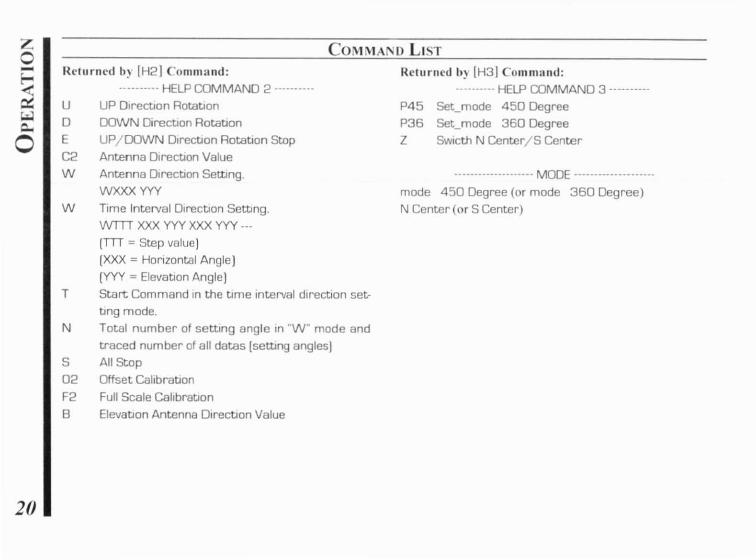
RClUrncd b) [H2! COIHI1l:Hld:.......... HELP COMMANO 2 .
U UP Olrec~on Rota~on
o DOWN Direc~on Rota~on
E UP/DOWN Dlrec~onRotation StopC2 Antenna D,recbOn Value
W Antenna D,recbOn Setting.
WXXX YYV
W Time IntelVal D,rectJOn Setting.WTn XXX yyy XXX yyy ...
[Tn = Step value)(XXX = Horizontal Angle)
[YYV = Eleva~on AngleIT Start Command In the time Interval direction set
ting mode.
N Total number of setting angle In "w" mode andtraced number of all datas (setting angles)
S All Stop
02 Offset Cahbra~on
F2 Full Scale Callbra~on
B Eleva~on Antenna D,rectJOn Value
Returned b) (H3] Command:.......... HELP COMMAND 3 .
P45 Set_mode 450 DegreeP36 Set_mode 360 Degree
Z SWICth N Center/S Center
.................... MODE .
mode 450 Degree (or mode 360 Degree)N Center (or S Center)

1I
: :
,~.
~
"..... .. n....... 'w. •._~ .,~:.0" .M...... ..r: t t..;. 1"1 _.\.1'
l"j·. ."'1' •
.. I":':" I'
-":"1' 1I~ ,
... \ I"
,- 1_ .. ~ 'M '~ , .
!'" ,'.•:[
. ~I'
~,
• •','.
•
" . ..," ,. . '", ..• .... ~" ""1. H' ,., ,,,.'...,. ..... /" W .:f ~t I .' '!'."'j'.,. ":'L .1"\.1:' ,~l'~ l' 1 1'·"'
'1~
CiRCUIT DIAGRAM

~~YAESU
Copyright 2004VERTEX STA DARD CO.. LTD.All rights reserved.
No portion of Ihis manualIllay be reprod lIccd
without the permission ofVERTEX STANDARD CO.. LTD.
Primed in Japan 040 I p.()[ 1111111111111111111111111111111111111111111111111111111
EAA14X101


![1261084 82 GS-30, GS-32, GS-46, GS-47 Slab Scissor [CE] · Operator's Manual CE GS™-1530/32 GS™-1930/32 GS™-2032 GS™-2632 GS™-3232 with Maintenance Information GS™-2046](https://static.fdocuments.us/doc/165x107/5f723aded681a6518a11728a/1261084-82-gs-30-gs-32-gs-46-gs-47-slab-scissor-ce-operators-manual-ce-gsa-153032.jpg)