GRUNDFOS DATA BOOKLET - · PDF fileType key 4 High motor ... from 3.7 kW 6" up to 250 kW 12"...
50
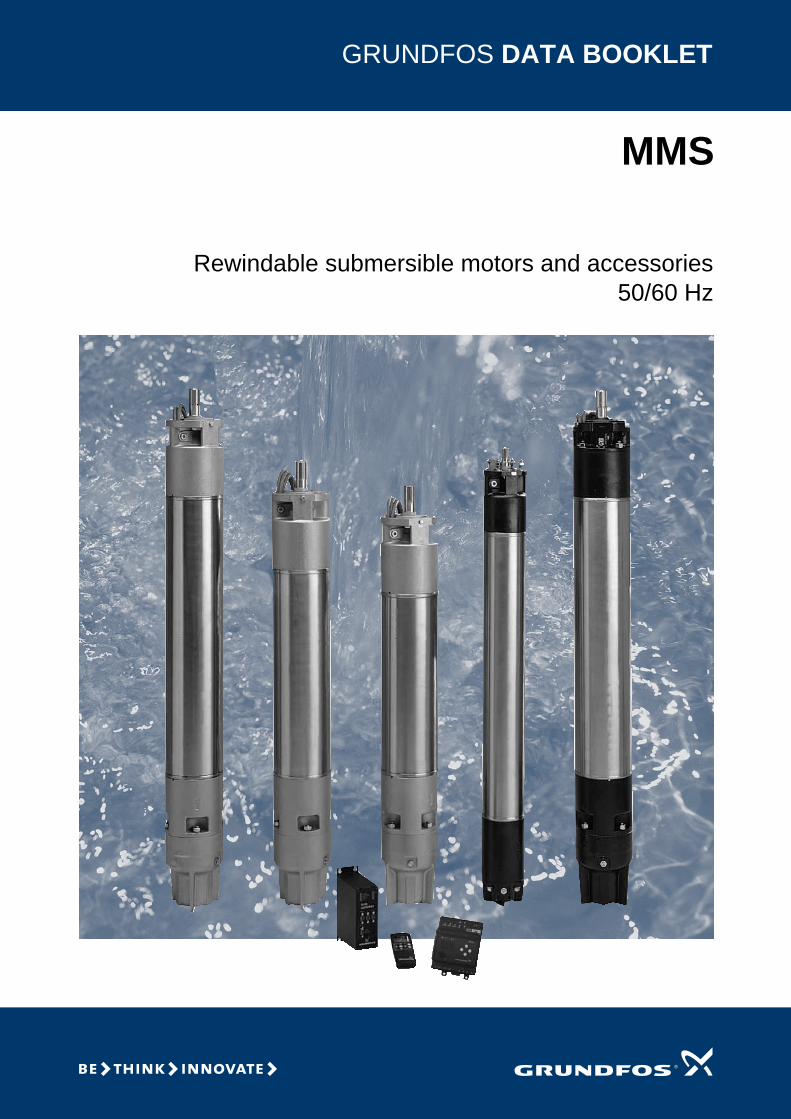
GRUNDFOS DATA BOOKLET MMS Rewindable submersible motors and accessories 50/60 Hz
Transcript of GRUNDFOS DATA BOOKLET - · PDF fileType key 4 High motor ... from 3.7 kW 6" up to 250 kW 12"...
GRUNDFOS DATA BOOKLET
MMS
Rewindable submersible motors and accessories50/60 Hz

2
Contents
General dataMMS rewindable motors 3Product range, 50 Hz 4Product range, 60 Hz 4Rewindable motors 4Type key 4High motor efficiency 4Overtemperature protection 4Protection against upthrust 5Motor protection range and communication tools 5Operation 5Name plate 5Voltage quality 5Operating conditions 6Windings temperature 6
ConstructionMaterial specification for MMS 6000 to MMS 12000 7Pump connection 8Shaft and radial bearing 8Shaft seal 8Motor 8Stator 9Thrust bearing 9Upthrust bearing 9Diaphragm 9Motor liquid 9
Technical dataMMS 6000 (N) 10MMS 8000 (N) 11MMS 10000 (N) 12MMS 12000 (N) 13
Electrical data3 x 220 V, 50 Hz 143 x 230 V, 50 Hz 143 x 380 V, 50 Hz 153 x 400 V, 50 Hz 163 x 415 V, 50 Hz 173 x 500 V, 50 Hz 183 x 220 V, 60 Hz and 3 x 380 V 60 Hz 193 x 460 V, 60 Hz and 3 x 575 V, 60 Hz 20
InstallationWiring diagram 21
AccessoriesMP 204 22Control functions 25G100 - Gateway for communication with Grundfos products 28Cable termination kit, type KM 30Cable termination kit, types M0 to M6 30Submersible drop cable 31Pt100 32
Cable SizingDrop cables 33Sizing of cable 40
Order data3 x 220 V, 60 Hz 413 x 220-230 V, 50 Hz 423 x 380-415 V, 50 Hz and 3 x 460 V, 60 Hz 433 x 380-415 V, 50 Hz and 3 x 460 V, 60 Hz 443 x 500 V, 50 Hz and 3 x 575 V, 60 Hz 453 x 380 V, 60 Hz, PVC windings 463 x 380 V, 60 Hz, PE/PA windings 47
Further product documentationWebCAPS 48WinCAPS 49

MMSGeneral data
MMS rewindable motorsThe Grundfos MMS product range is a complete range of submersible, rewindable motors, available in sizes from 3.7 kW 6" up to 250 kW 12" motors.
Three material versions are available. A cast iron version EN-JL1040. For more aggressive liquids with a moderate content of salt, an N-version made of stainless steel DIN/EN 1.4401 (AISI 316) is available. For agressive liquids with more salt content than sea water and temperatures above 15 deg celsius, it is recommended to use the R version AISI 904L.
Grundfos MMS submersible motors are designed
according to market standards. All Grundfos MMS motors are designed to fit pump ends manufactured according to NEMA standards. The motors are ideally suited for water supply pumps for irrigation, groundwater regulation, pressure boosting, industrial water transfer and similar applications. The 10" and 12" motors are designed according to the drawings shown on page 8. MMS motors comply with the same standards as Grundfos MS motors and can therefore be fitted on all Grundfos SP pumps without the need for adapters.
The motor production is in the hands of experts with many years of experience within the manufacture of motors. In order to make the time of delivery as short as possible, components are manufactured for stock, enabling rapid assembly of a few basic components into the finished motor.
The rewindable motor construction means low costs of repair of the motor in case of damage. Moreover, as rewinding can be effected locally, unnecessary time for transportation of the motor can be avoided and possible periods of downtime reduced to a minimum. The construction of the motor, based on few basic components, also facilitates service and repair of the motor.
Fitted with a sturdy MICHELL thrust bearing, which also functions as an upthrust bearing, all motors offer reliable operation.
In order to achieve maximum protection of the motor against burnout, all motors can be fitted with a Pt100 sensor. Combined with a relay and an optional Grundfos MP 402, the Pt100 provides optimum protection of the motor.
Fig. 1 MMS motors
TM01
787
3 49
99
3

4
General data MMS
Product range, 50 Hz
Note: * = 37 kW, R-version only
Product range, 60 Hz
Note: * = 37 kW, R-version only
Rewindable motorsThe two pole MMS motors are easily rewinded. The windings of the stator are made of a special water-proof wire of pure electrolytic copper sheathed with special non-hydroscopic thermoplastic material. The high dielectric strength properties of this material allow direct contact between the windings and the liquid for efficient cooling of the windings.
Type key
High motor efficiency The complete motor range offered by Grundfos is characterized by high efficiency, which contributes to improved economy of the total pump system.
Overtemperature protectionFor protection against overtemperature, Grundfos offers the Pt100 temperature sensor as an optional extra.
The Pt100 is fitted in the motor and connected via a relay, which can be connected to the MP204 motor protection.
When the temperature becomes too high, the motor will be cut out and damage to the pump be avoided.
MMS 6000 (N/R) MMS 8000 (N/R) MMS 10000 (N) MMS 12000 (N)
Motor size 6" 8" 10" 12"
Power range, direct-on-line and star-delta- 3 x 220-230 V
3.7-37* kW22-63 kW 75-110 kW
- 3 x 380-415 V22-110 kW 75-190 kW 147-250 kW
- 3 x 500 V 7.5-37* kW
Allowed installation- Vertical 3.7- 37* kW 22-110 kW 75-190 kW 147-250 kW- Horizontal 3.7- 30 kW 22-92 kW 75-170 kW 147-190 kW
MMS 6000 (N/R) MMS 8000 (N/R) MMS 10000 (N)
Motor size 6" 8" 10"
Power range, direct-on-line and star-delta- 3 x 220 V 3.7-37* kW 22-75 kW 75-132 kW- 3 x 380 V 3.7-37* kW 22-110 kW 75-190 kW- 3 x 460 V 3.7-37* kW 22-110 kW 75-190 kW
Power range, direct-on-line- 3 x 575 V 22-110 kW 75-190 kW
Allowed installation- Vertical 3.7- 37* kW 22-110 kW 75-190 kW- Horizontal 3.7- 30 kW 22-92 kW 75-170 kW
Example MMS 6 000 N
Type range
Min. borehole diameter in inches
Generation
Material:= Cast iron EN-JL1040
N = DIN/EN 1.4401 (AISI 316)R = DIN W.-Nr. 1.4539
General data MMS
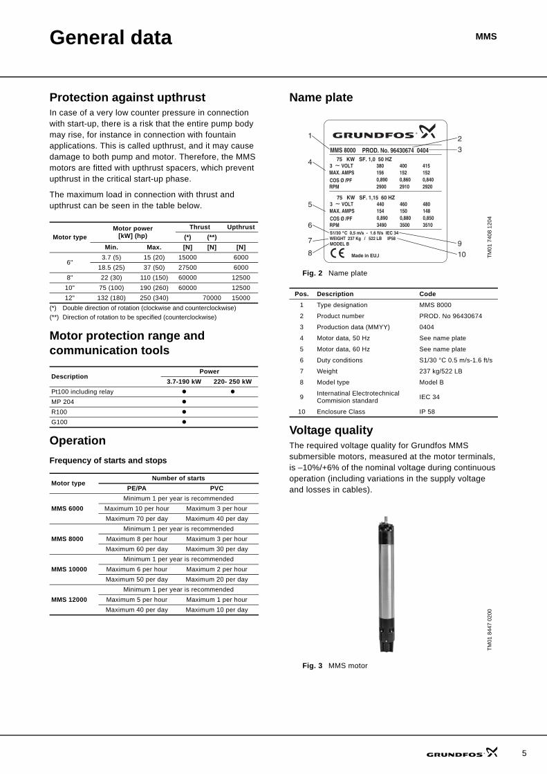
Protection against upthrustIn case of a very low counter pressure in connection with start-up, there is a risk that the entire pump body may rise, for instance in connection with fountain applications. This is called upthrust, and it may cause damage to both pump and motor. Therefore, the MMS motors are fitted with upthrust spacers, which prevent upthrust in the critical start-up phase.
The maximum load in connection with thrust and upthrust can be seen in the table below.
Motor protection range and communication tools
OperationFrequency of starts and stops
Name plate
Fig. 2 Name plate
Voltage qualityThe required voltage quality for Grundfos MMS submersible motors, measured at the motor terminals, is –10%/+6% of the nominal voltage during continuous operation (including variations in the supply voltage and losses in cables).
Fig. 3 MMS motor
Motor typeMotor power
[kW] (hp)Thrust Upthrust
(*) (**)Min. Max. [N] [N] [N]
6"3.7 (5) 15 (20) 15000 6000
18.5 (25) 37 (50) 27500 60008" 22 (30) 110 (150) 60000 12500
10" 75 (100) 190 (260) 60000 1250012" 132 (180) 250 (340) 70000 15000
(*) Double direction of rotation (clockwise and counterclockwise)(**) Direction of rotation to be specified (counterclockwise)
DescriptionPower
3.7-190 kW 220- 250 kWPt100 including relayMP 204R100G100
Motor typeNumber of starts
PE/PA PVC
MMS 6000Minimum 1 per year is recommended
Maximum 10 per hour Maximum 3 per hourMaximum 70 per day Maximum 40 per day
MMS 8000Minimum 1 per year is recommended
Maximum 8 per hour Maximum 3 per hour Maximum 60 per day Maximum 30 per day
MMS 10000Minimum 1 per year is recommended
Maximum 6 per hour Maximum 2 per hourMaximum 50 per day Maximum 20 per day
MMS 12000Minimum 1 per year is recommended
Maximum 5 per hour Maximum 1 per hourMaximum 40 per day Maximum 10 per day
TM01
740
8 12
04
Pos. Description Code1 Type designation MMS 8000
2 Product number PROD. No 96430674
3 Production data (MMYY) 0404
4 Motor data, 50 Hz See name plate
5 Motor data, 60 Hz See name plate
6 Duty conditions S1/30 °C 0.5 m/s-1.6 ft/s
7 Weight 237 kg/522 LB
8 Model type Model B
9 Internatinal Electrotechnical Commision standard IEC 34
10 Enclosure Class IP 58
TM01
844
7 02
00
MMS 8000 PROD. No. 96430674 040475 KW SF. 1,0 50 HZ
3 ~ VOLTMAX. AMPSCOS Ø /PFRPM
Made in EU,I
3
1
4
5
6
380156
2900
400152
2910
415152
29200,890 0,860 0,840
75 KW SF. 1,15 60 HZ3 ~ VOLTMAX. AMPSCOS Ø /PFRPM
440154
3490
460150
3500
480148
35100,890 0,880 0,850
S1/30 ˚C 0,5 m/s - 1.6 ft/s IEC 34WEIGHT 237 Kg / 522 LB IP58MODEL B7
8
2
10
9
5
6
General data MMS
Operating conditionsCoolingThe cooling of the motor depends on the temperature and the flow velocity of the pumped liquid past the motor.
To ensure sufficient cooling, the values for maximum temperature of the pumped liquid and its flow velocity must be kept.
It is reccomended always to ensure a minimum cooling flow of 0.15 m/s.
Free convectionFree convection is achieved when the diameter of the borehole is at least 2" (~ 50 mm) bigger than the outer diameter of the motor.
The motor must always be installed above the borehole screen. If a flow sleeve is used, the motor can be placed in the screen.
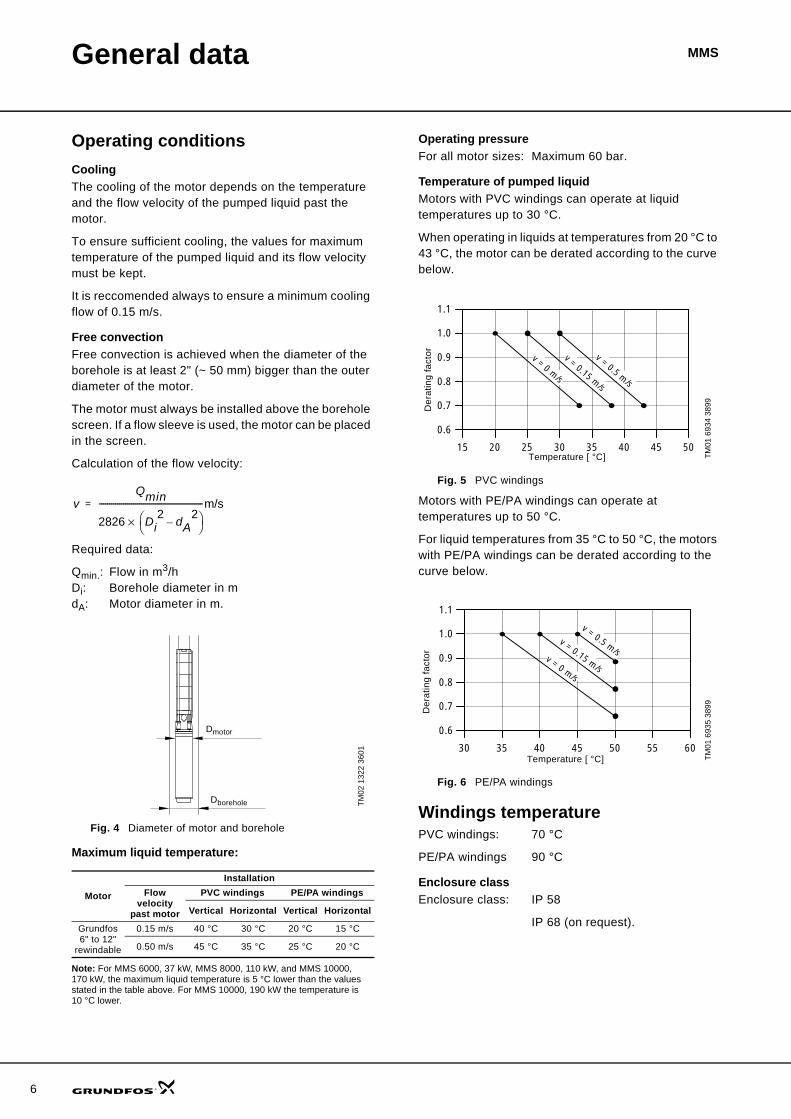
Calculation of the flow velocity:
Required data:
Qmin.: Flow in m3/hDi: Borehole diameter in mdA: Motor diameter in m.
Fig. 4 Diameter of motor and borehole
Maximum liquid temperature:
Note: For MMS 6000, 37 kW, MMS 8000, 110 kW, and MMS 10000, 170 kW, the maximum liquid temperature is 5 °C lower than the values stated in the table above. For MMS 10000, 190 kW the temperature is 10 °C lower.
Operating pressureFor all motor sizes: Maximum 60 bar.
Temperature of pumped liquidMotors with PVC windings can operate at liquid temperatures up to 30 °C.
When operating in liquids at temperatures from 20 °C to 43 °C, the motor can be derated according to the curve below.
Fig. 5 PVC windings
Motors with PE/PA windings can operate at temperatures up to 50 °C.
For liquid temperatures from 35 °C to 50 °C, the motors with PE/PA windings can be derated according to the curve below.
Fig. 6 PE/PA windings
Windings temperaturePVC windings: 70 °C
PE/PA windings 90 °C
Enclosure classEnclosure class: IP 58
IP 68 (on request).
TM02
132
2 36
01
Motor
InstallationFlow
velocity past motor
PVC windings PE/PA windings
Vertical Horizontal Vertical Horizontal
Grundfos6" to 12"
rewindable
0.15 m/s 40 °C 30 °C 20 °C 15 °C
0.50 m/s 45 °C 35 °C 25 °C 20 °C
vQmin
2826 Di2 dA
2–⎝ ⎠
⎛ ⎞×----------------------------------------------------m/s=
Dmotor
Dborehole
TM01
693
4 38
99TM
01 6
935
3899
15 20 25 30 35 40 45 50
0.6
0.7
0.8
0.9
1.0
1.1
v = 0 m/s
v = 0.15 m/s
v = 0.5 m/s
Temperature [ °C]
Der
atin
g fa
ctor
30 35 40 45 50 55 60
0.6
0.7
0.8
0.9
1.0
1.1
v = 0 m/s
v = 0.15 m/s
v = 0.5 m/s
Temperature [ °C]
Der
atin
g fa
ctor
MMSConstruction
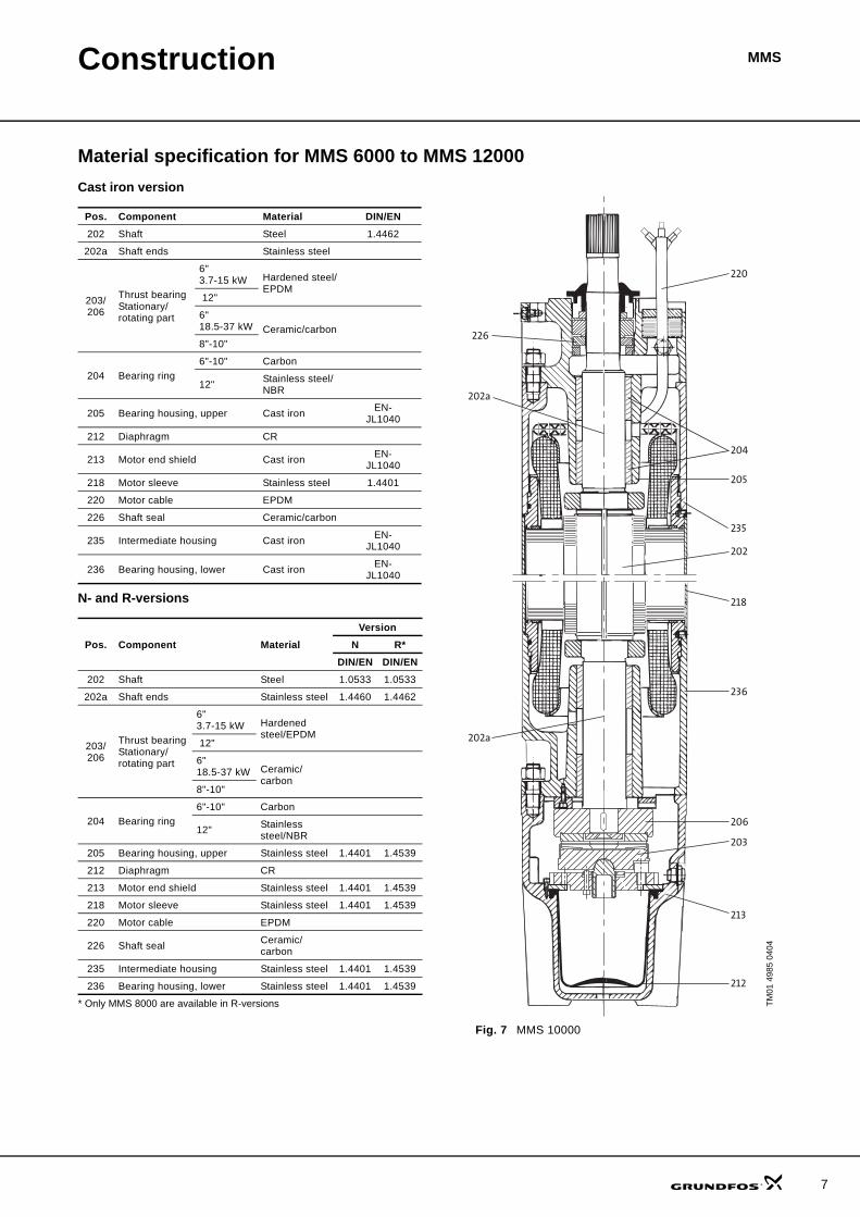
Material specification for MMS 6000 to MMS 12000Cast iron version
N- and R-versions
Fig. 7 MMS 10000
Pos. Component Material DIN/EN202 Shaft Steel 1.4462
202a Shaft ends Stainless steel
203/206
Thrust bearingStationary/rotating part
6" 3.7-15 kW Hardened steel/
EPDM 12"
6" 18.5-37 kW Ceramic/carbon8"-10"
204 Bearing ring6"-10" Carbon
12" Stainless steel/ NBR
205 Bearing housing, upper Cast iron EN-JL1040
212 Diaphragm CR
213 Motor end shield Cast iron EN-JL1040
218 Motor sleeve Stainless steel 1.4401
220 Motor cable EPDM
226 Shaft seal Ceramic/carbon
235 Intermediate housing Cast iron EN-JL1040
236 Bearing housing, lower Cast iron EN-JL1040
Pos. Component MaterialVersion
N R*DIN/EN DIN/EN
202 Shaft Steel 1.0533 1.0533
202a Shaft ends Stainless steel 1.4460 1.4462
203/206
Thrust bearingStationary/rotating part
6"3.7-15 kW Hardened
steel/EPDM 12"
6"18.5-37 kW Ceramic/
carbon8"-10"
204 Bearing ring6"-10" Carbon
12" Stainless steel/NBR
205 Bearing housing, upper Stainless steel 1.4401 1.4539
212 Diaphragm CR
213 Motor end shield Stainless steel 1.4401 1.4539
218 Motor sleeve Stainless steel 1.4401 1.4539
220 Motor cable EPDM
226 Shaft seal Ceramic/carbon
235 Intermediate housing Stainless steel 1.4401 1.4539
236 Bearing housing, lower Stainless steel 1.4401 1.4539
* Only MMS 8000 are available in R-versions TM01
498
5 04
04
220
204
205
235
202
218
236
206
203
213
212
202a
202a
226
7
8
Construction MMS
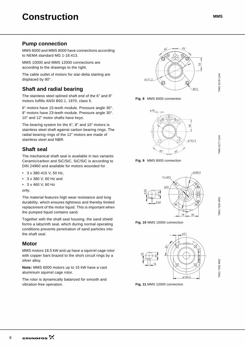
Pump connectionMMS 6000 and MMS 8000 have connections according to NEMA standard MG 1-18.413.
MMS 10000 and MMS 12000 connections are according to the drawings to the right.
The cable outlet of motors for star-delta starting are displaced by 90°.
Shaft and radial bearingThe stainless steel splined shaft end of the 6" and 8" motors fulfills ANSI B92.1, 1970, class 5.
6" motors have 15-teeth module. Pressure angle 30°.8" motors have 23-teeth module. Pressure angle 30°.10" and 12" motor shafts have keys.
The bearing system for the 6", 8" and 10" motors is stainless steel shaft against carbon bearing rings. The radial bearing rings of the 12" motors are made of stainless steel and NBR.
Shaft sealThe mechanical shaft seal is available in two variants: Ceramic/carbon and SiC/SiC. SiC/SiC is according to DIN 24960 and available for motors wounded for
• 3 x 380-415 V, 50 Hz, • 3 x 380 V, 60 Hz and • 3 x 460 V, 60 Hz only.
The material features high wear resistance and long durability, which ensures tightness and thereby limited replacement of the motor liquid. This is important when the pumped liquid contains sand.
Together with the shaft seal housing, the sand shield forms a labyrinth seal, which during normal operating conditions prevents penetration of sand particles into the shaft seal.
MotorMMS motors 18.5 kW and up have a squirrel cage rotor with copper bars brazed to the short circuit rings by a silver alloy.
Note: MMS 6000 motors up to 15 kW have a cast aluminium squirrel cage rotor.
The rotor is dynamically balanced for smooth and vibration-free operation.
Fig. 8 MMS 6000 connection
Fig. 9 MMS 8000 connection
Fig. 10 MMS 10000 connection
Fig. 11 MMS 12000 connection
TM01
817
8 11
04TM
01 8
177
1104
TM01
732
8 49
02TM
01 7
330
4902
50
45˚ 45˚
ø111.2
M12
45˚ 45˚
ø18
68
ø152.5
4 x ø21
ø190.5
78 95
9.52
9.52
47.6
ø43
59
16
10
ø21
ø190.5
45˚

Construction MMS
StatorThe stator is a wet-wound construction in stainless steel to protect the motor, even in corrosive water. The stator design allows complete access to the winding for easy maintenance and rewinding. The construction of the laminations minimizes operating losses and improves motor performance.
In 6", 8", and 10" motors, the motor end shield is screwed onto the stator. A suitable centring assures alignment of rotor and stator.
Thrust bearingThe MICHELL/Kingsbury type of water-lubricated thrust bearing is very simple and most efficient.
The thrust capacity of the bearings is in accordance with NEMA standards for submersible motors, where these are applicable. See drawing to the below.
Upthrust bearingThe EPDM upthrust spacers placed above the rotating bearing part prevent motor damage during transportation or in case of upthrust in connection with start-up.
The upthrust bearing is an integrated part of the thrust bearing.
DiaphragmThe diaphragm (pos. no. 3) is fitted between the stator and the motor end shield. The diaphragm is dimensioned to equalize pressure variations caused by temperature rises in connection with intermittent operation.
Fig. 12 MMS 8000
1. Rotating bearing part2. Stationary bearing part3. Diaphragm.
Motor liquidThe motor is filled with glycerol-containing motor liquid, which is frost-proof down to –20°C.
The motor liquid has an anti-corrosive and lubricating function. To obtain the best protection, a concentration of 40% to 60% in water is recommended.
Should the glycerol-containing motor liquid mixed with water not be allowed for special applications, MMS motors may be filled even with fresh water.
Motors not filled with motor liquid are available on request. The following table indicates the freezing points obtainable with various percentages of glycerol-containing motor liquid..
TM01
733
1 06
04
1
2
3
Glycerol-containing motor liquid % volume
Freezing point[°C]
40 –3,950 –11,560 –15,270 –2080 –26,790 –36,5
100 –46,5
9
10
Technical data
MMS 6000 (N)
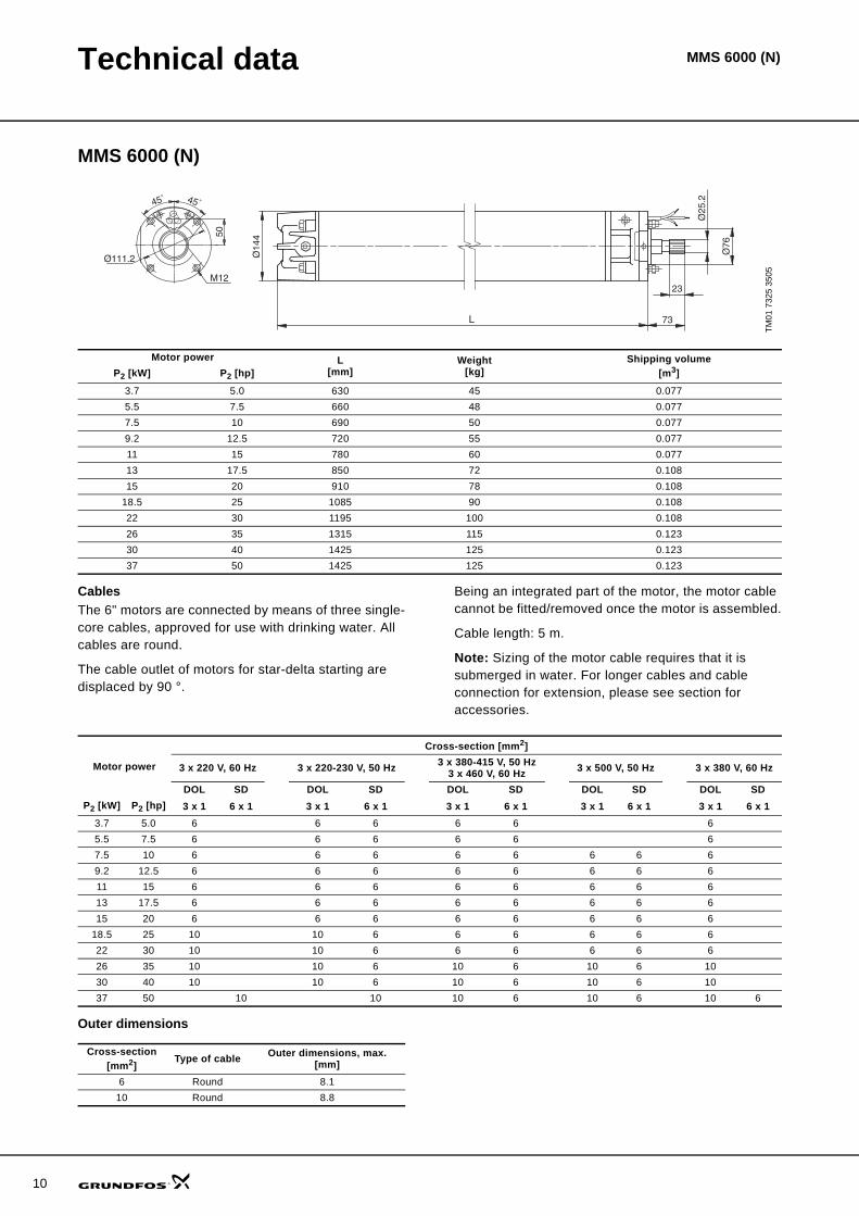
CablesThe 6" motors are connected by means of three single-core cables, approved for use with drinking water. All cables are round.
The cable outlet of motors for star-delta starting are displaced by 90 °.
Being an integrated part of the motor, the motor cable cannot be fitted/removed once the motor is assembled.
Cable length: 5 m.
Note: Sizing of the motor cable requires that it is submerged in water. For longer cables and cable connection for extension, please see section for accessories.
Outer dimensions
TM01
732
5 35
05
Ø14
4
M12
50
45˚ 45˚
Ø111.2
L
Ø25
.2
Ø76
23
73
Motor power L[mm]
Weight[kg]
Shipping volume[m3]P2 [kW] P2 [hp]
3.7 5.0 630 45 0.0775.5 7.5 660 48 0.0777.5 10 690 50 0.0779.2 12.5 720 55 0.07711 15 780 60 0.07713 17.5 850 72 0.10815 20 910 78 0.108
18.5 25 1085 90 0.10822 30 1195 100 0.10826 35 1315 115 0.12330 40 1425 125 0.12337 50 1425 125 0.123
Motor power
Cross-section [mm2]
3 x 220 V, 60 Hz 3 x 220-230 V, 50 Hz 3 x 380-415 V, 50 Hz3 x 460 V, 60 Hz 3 x 500 V, 50 Hz 3 x 380 V, 60 Hz
DOL SD DOL SD DOL SD DOL SD DOL SDP2 [kW] P2 [hp] 3 x 1 6 x 1 3 x 1 6 x 1 3 x 1 6 x 1 3 x 1 6 x 1 3 x 1 6 x 1
3.7 5.0 6 6 6 6 6 65.5 7.5 6 6 6 6 6 67.5 10 6 6 6 6 6 6 6 69.2 12.5 6 6 6 6 6 6 6 611 15 6 6 6 6 6 6 6 613 17.5 6 6 6 6 6 6 6 615 20 6 6 6 6 6 6 6 6
18.5 25 10 10 6 6 6 6 6 622 30 10 10 6 6 6 6 6 626 35 10 10 6 10 6 10 6 1030 40 10 10 6 10 6 10 6 1037 50 10 10 10 6 10 6 10 6
Cross-section [mm2]
Type of cable Outer dimensions, max.[mm]
6 Round 8.110 Round 8.8
MMS 6000 (N)

Technical data MMS 6000 (N)
MMS 8000 (N)
CablesThe 8" motors are connected by means of three single-core cables, approved for use with drinking water. All cables are round.
The cable outlet of star-delta motors are displaced by 90°.
Being an integrated part of the motor, the motor cable cannot be fitted/removed once the motor is assembled.
Cable length: 8 m.
Note: Sizing of the motor cable requires that it is submerged in water. For longer cables and cable connection for extension, please see section for accessories.
Outer dimensions
TM01
732
6 11
04
45
L
Ø19
2
101.6
Ø38
.1
Ø12
7
45˚ 45˚
Ø18
68
Ø152.5
Motor power L[mm]
Weight[kg]
Shipping volume[m3]P2 [kW] P2 [hp]
22 30 1010 126 0.15626 35 1050 134 0.15630 40 1110 146 0.15637 50 1160 156 0.15645 60 1270 177 0.15655 75 1350 192 0.18763 85 1490 218 0.18775 100 1590 237 0.18792 125 1830 283 0.239110 150 2060 333 0.239
Motor power
Cross-section [mm2]
3 x 220 V, 60 Hz 3 x 220-230 V, 50 Hz 3 x 380-415 V, 50 Hz3 x 460 V, 60 Hz
3 x 500 V, 50 Hz3 x 575 V, 60 Hz 3 x 380 V, 60 Hz
DOL SD DOL SD DOL SD DOL SD DOL SDP2 [kW] P2 [hp] 3 x 1 6 x 1 3 x 1 6 x 1 3 x 1 6 x 1 3 x 1 6 x 1 3 x 1 6 x 1
22 30 16 10 16 10 16 10 16 10 16 1026 35 16 10 16 10 16 10 16 10 16 1030 40 16 10 16 10 16 10 16 10 16 1037 50 16 16 16 16 16 10 16 10 16 1045 60 25 16 25 16 16 10 16 10 16 1655 75 25 16 25 16 16 16 16 16 16 1663 85 25 16 25 16 16 16 16 16 16 1675 100 25 16 16 16 16 16 16 1692 125 25 16 25 16 25 16110 150 25 16 25 16 25 16
Cross-section [mm2]
Type of cable Outer dimensions, max.[mm]
10 Round 8.816 Round 10.725 Round 12.1
11

12
Technical data MMS 6000 (N)
MMS 10000 (N)
CablesThe 10" motors are connected by means of three single-core cables, approved for use with drinking water. All cables are round.
The cable outlet of star-delta motors are displaced by 90 °.
Being an integrated part of the motor, the motor cable cannot be fitted/removed once the motor is assembled.
Cable length: 8 m.
Note: Sizing of the motor cable requires that it is submerged in water. For longer cables and cable connection for extension, please see section for accessories.
Outer dimensions
TM01
732
7 37
01
Motor power L[mm]
Weight[kg]
Shipping volume[m3]P2 [kW] P2 [hp]
75 100 1400 280 0.41592 125 1500 330 0.415110 150 1690 385 0.415132 180 1870 435 0.494147 200 2070 500 0.494170 230 2220 540 0.564190 260 2400 580 0.564
Motor power
Cross-section [mm2]
3 x 220 V, 60 Hz 3 x 220-230 V, 50 Hz 3 x 380-415 V, 50 Hz3 x 460 V, 60 Hz
3 x 500 V, 50 Hz3 x 575, 60 Hz 3 x 380 V, 60 Hz
DOL SD DOL SD DOL SD DOL SD DOL SDP2 [kW] P2 [hp] 3 x 1 6 x 1 3 x 1 6 x 1 3 x 1 6 x 1 3 x 1 6 x 1 3 x 1 6 x 1
75 100 50 50 35 50 35 50 35 50 3592 125 50 50 35 50 35 50 35 50 35110 150 50 50 35 50 35 50 35 50 35132 180 50 50 35 50 35 50 35147 200 50 35 50 35 50 35170 230 50 35 50 35 50 35190 260 50 35 50 35 50 35
Cross-section [mm2]
Type of cable Outer dimensions, max.[mm]
35 Round 14.250 Round 16.1
Technical data MMS 6000 (N)
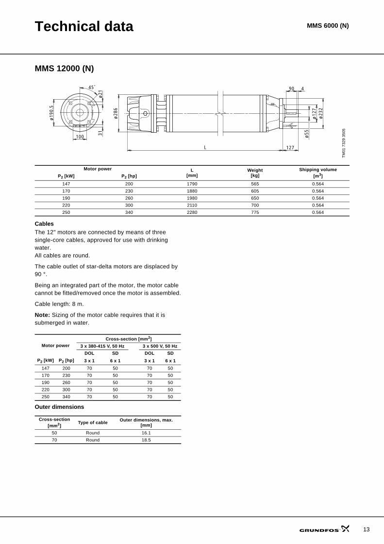
MMS 12000 (N)
CablesThe 12" motors are connected by means of three single-core cables, approved for use with drinking water.All cables are round.
The cable outlet of star-delta motors are displaced by 90 °.
Being an integrated part of the motor, the motor cable cannot be fitted/removed once the motor is assembled.
Cable length: 8 m.
Note: Sizing of the motor cable requires that it is submerged in water.
Outer dimensions
TM01
732
9 35
05
Motor power L[mm]
Weight[kg]
Shipping volume[m3]P2 [kW] P2 [hp]
147 200 1790 565 0.564170 230 1880 605 0.564190 260 1980 650 0.564220 300 2110 700 0.564250 340 2280 775 0.564
ø19
0.5
ø21
31
ø28
6
100
L
ø12
7
90
127
ø23
2
ø55
445
Motor powerCross-section [mm2]
3 x 380-415 V, 50 Hz 3 x 500 V, 50 HzDOL SD DOL SD
P2 [kW] P2 [hp] 3 x 1 6 x 1 3 x 1 6 x 1147 200 70 50 70 50170 230 70 50 70 50190 260 70 50 70 50220 300 70 50 70 50250 340 70 50 70 50
Cross-section [mm2]
Type of cable Outer dimensions, max.[mm]
50 Round 16.170 Round 18.5
13
14
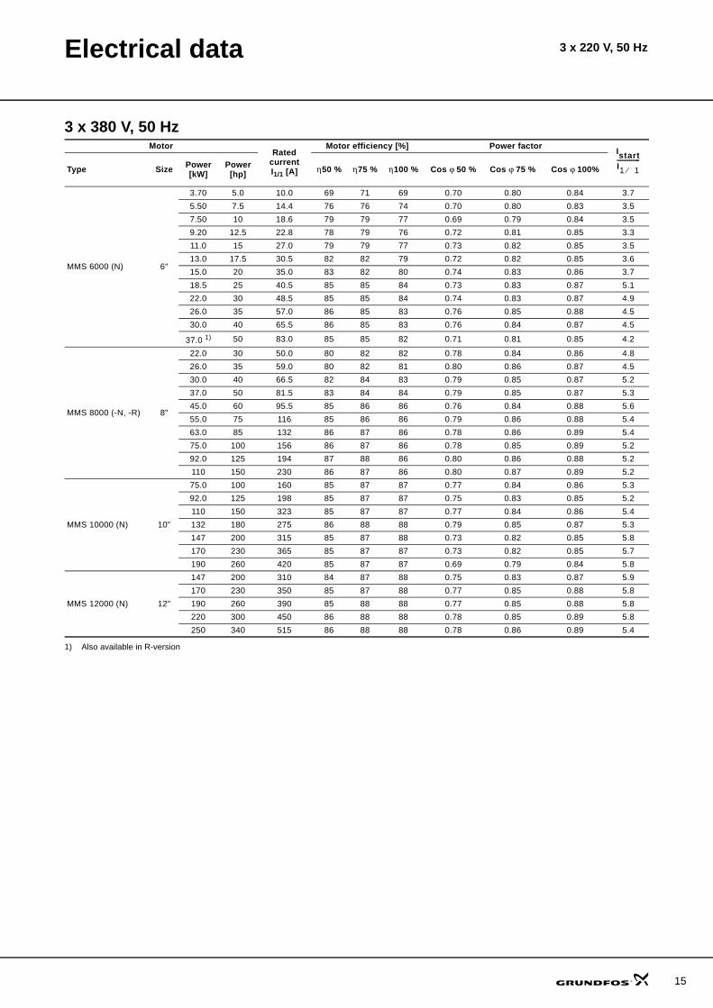
Electrical data
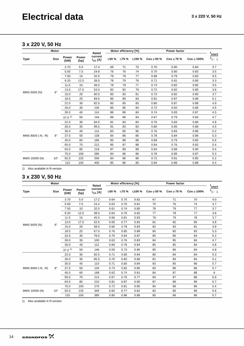
3 x 220 V, 50 Hz
1) Also available in R-version
3 x 230 V, 50 Hz
1) Also available in R-version
MotorRated
current I1/1 [A]
Motor efficiency [%] Power factor
Type Size Power[kW]
Power[hp] η 50 % η 75 % η 100 % Cos ϕ 50 % Cos ϕ 75 % Cos ϕ 100%
MMS 6000 (N) 6"
3.70 5.0 17.4 69 71 70 0.70 0.80 0.84 3.75.50 7.5 24.8 76 76 74 0.70 0.80 0.83 3.57.50 10 32.5 79 79 77 0.68 0.79 0.83 3.59.20 12.5 39.5 78 79 76 0.71 0.81 0.85 3.311.0 15 46.0 79 79 77 0.73 0.82 0.85 3.513.0 17.5 53.0 82 82 79 0.72 0.82 0.85 3.615.0 20 60.5 83 83 81 0.73 0.82 0.85 3.718.5 25 69.5 85 85 83 0.81 0.87 0.89 5.122.0 30 82.5 85 85 83 0.80 0.87 0.88 4.926.0 35 100 85 85 84 0.72 0.82 0.86 4.530.0 40 114 86 86 84 0.74 0.83 0.87 4.5
37.0 1) 50 144 86 86 84 0.67 0.79 0.84 4.7
MMS 8000 (-N, -R) 8"
22.0 30 84.5 81 84 84 0.76 0.83 0.86 4.826.0 35 99.5 81 83 83 0.80 0.85 0.86 4.530.0 40 114 83 85 85 0.76 0.83 0.86 5.237.0 50 138 84 86 86 0.78 0.84 0.86 5.345.0 60 166 85 88 88 0.69 0.79 0.85 5.655.0 75 212 85 87 88 0.64 0.76 0.82 5.463.0 85 218 87 89 88 0.84 0.89 0.90 5.4
MMS 10000 (N) 10"75.0 100 280 84 86 86 0.78 0.85 0.87 5.392.0 125 350 84 86 86 0.72 0.81 0.85 5.2110 150 405 85 86 85 0.84 0.88 0.88 5.4
IstartI1 1⁄-------------
MotorRated
current I1/1 [A]
Motor efficiency [%] Power factor
Type Size Power[kW]
Power[hp] η 50 % η 75 % η 100 % Cos ϕ 50 % Cos ϕ 75 % Cos ϕ 100%
MMS 6000 (N) 6"
3.70 5.0 17.2 0.64 0.75 0.82 67 71 70 4.05.50 7.5 24.2 0.63 0.75 0.81 75 76 74 3.77.50 10 32.0 0.61 0.74 0.80 78 79 77 3.79.20 12.5 38.5 0.64 0.76 0.82 77 78 77 3.611.0 15 45.5 0.66 0.81 0.83 78 79 78 3.713.0 17.5 52.5 0.65 0.77 0.82 81 82 80 3.815.0 20 58.5 0.66 0.78 0.83 82 83 81 3.818.5 25 67.0 0.76 0.85 0.88 85 85 83 5.322.0 30 79.5 0.75 0.84 0.87 85 85 84 5.226.0 35 100 0.63 0.76 0.83 84 85 84 4.730.0 40 112 0.66 0.78 0.84 85 85 84 4.8
37.0 1) 50 146 0.59 0.73 0.80 85 86 84 4.8
MMS 8000 (-N, -R) 8"
22.0 30 82.5 0.71 0.80 0.84 80 84 84 5.326.0 35 95.5 0.76 0.83 0.86 81 84 84 5.130.0 40 110 0.71 0.80 0.84 83 85 86 5.737.0 50 134 0.73 0.82 0.85 83 86 86 5.745.0 60 168 0.62 0.74 0.81 84 87 88 655.0 75 214 0.57 0.70 0.77 84 87 88 5.963.0 85 210 0.81 0.87 0.90 87 89 89 5.7
MMS 10000 (N) 10"75.0 100 270 0.72 0.81 0.85 84 86 86 5.492.0 125 345 0.65 0.77 0.82 83 85 86 5.6110 150 385 0.80 0.86 0.88 85 86 86 5.7
IstartI1 1⁄-------------
3 x 220 V, 50 Hz
Electrical data 3 x 220 V, 50 Hz
3 x 380 V, 50 Hz
1) Also available in R-version
MotorRated
current I1/1 [A]
Motor efficiency [%] Power factor
Type Size Power[kW]
Power[hp] η 50 % η 75 % η 100 % Cos ϕ 50 % Cos ϕ 75 % Cos ϕ 100%
MMS 6000 (N) 6"
3.70 5.0 10.0 69 71 69 0.70 0.80 0.84 3.75.50 7.5 14.4 76 76 74 0.70 0.80 0.83 3.57.50 10 18.6 79 79 77 0.69 0.79 0.84 3.59.20 12.5 22.8 78 79 76 0.72 0.81 0.85 3.311.0 15 27.0 79 79 77 0.73 0.82 0.85 3.513.0 17.5 30.5 82 82 79 0.72 0.82 0.85 3.615.0 20 35.0 83 82 80 0.74 0.83 0.86 3.718.5 25 40.5 85 85 84 0.73 0.83 0.87 5.122.0 30 48.5 85 85 84 0.74 0.83 0.87 4.926.0 35 57.0 86 85 83 0.76 0.85 0.88 4.530.0 40 65.5 86 85 83 0.76 0.84 0.87 4.5
37.0 1) 50 83.0 85 85 82 0.71 0.81 0.85 4.2
MMS 8000 (-N, -R) 8"
22.0 30 50.0 80 82 82 0.78 0.84 0.86 4.826.0 35 59.0 80 82 81 0.80 0.86 0.87 4.530.0 40 66.5 82 84 83 0.79 0.85 0.87 5.237.0 50 81.5 83 84 84 0.79 0.85 0.87 5.345.0 60 95.5 85 86 86 0.76 0.84 0.88 5.655.0 75 116 85 86 86 0.79 0.86 0.88 5.463.0 85 132 86 87 86 0.78 0.86 0.89 5.475.0 100 156 86 87 86 0.78 0.85 0.89 5.292.0 125 194 87 88 86 0.80 0.86 0.88 5.2110 150 230 86 87 86 0.80 0.87 0.89 5.2
MMS 10000 (N) 10"
75.0 100 160 85 87 87 0.77 0.84 0.86 5.392.0 125 198 85 87 87 0.75 0.83 0.85 5.2110 150 323 85 87 87 0.77 0.84 0.86 5.4132 180 275 86 88 88 0.79 0.85 0.87 5.3147 200 315 85 87 88 0.73 0.82 0.85 5.8170 230 365 85 87 87 0.73 0.82 0.85 5.7190 260 420 85 87 87 0.69 0.79 0.84 5.8
MMS 12000 (N) 12"
147 200 310 84 87 88 0.75 0.83 0.87 5.9170 230 350 85 87 88 0.77 0.85 0.88 5.8190 260 390 85 88 88 0.77 0.85 0.88 5.8220 300 450 86 88 88 0.78 0.85 0.89 5.8250 340 515 86 88 88 0.78 0.86 0.89 5.4
IstartI1 1⁄-------------
15
16
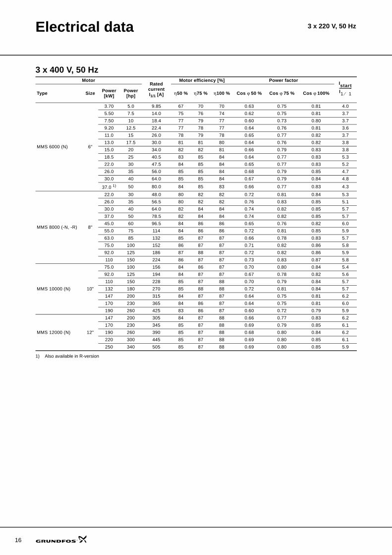
Electrical data 3 x 220 V, 50 Hz
3 x 400 V, 50 Hz
1) Also available in R-version
MotorRated
current I1/1 [A]
Motor efficiency [%] Power factor
Type Size Power[kW]
Power[hp] η 50 % η 75 % η 100 % Cos ϕ 50 % Cos ϕ 75 % Cos ϕ 100%
MMS 6000 (N) 6"
3.70 5.0 9.85 67 70 70 0.63 0.75 0.81 4.05.50 7.5 14.0 75 76 74 0.62 0.75 0.81 3.77.50 10 18.4 77 79 77 0.60 0.73 0.80 3.79.20 12.5 22.4 77 78 77 0.64 0.76 0.81 3.611.0 15 26.0 78 79 78 0.65 0.77 0.82 3.713.0 17.5 30.0 81 81 80 0.64 0.76 0.82 3.815.0 20 34.0 82 82 81 0.66 0.79 0.83 3.818.5 25 40.5 83 85 84 0.64 0.77 0.83 5.322.0 30 47.5 84 85 84 0.65 0.77 0.83 5.226.0 35 56.0 85 85 84 0.68 0.79 0.85 4.730.0 40 64.0 85 85 84 0.67 0.79 0.84 4.8
37.0 1) 50 80.0 84 85 83 0.66 0.77 0.83 4.3
MMS 8000 (-N, -R) 8"
22.0 30 48.0 80 82 82 0.72 0.81 0.84 5.326.0 35 56.5 80 82 82 0.76 0.83 0.85 5.130.0 40 64.0 82 84 84 0.74 0.82 0.85 5.737.0 50 78.5 82 84 84 0.74 0.82 0.85 5.745.0 60 96.5 84 86 86 0.65 0.76 0.82 6.055.0 75 114 84 86 86 0.72 0.81 0.85 5.963.0 85 132 85 87 87 0.66 0.78 0.83 5.775.0 100 152 86 87 87 0.71 0.82 0.86 5.892.0 125 186 87 88 87 0.72 0.82 0.86 5.9110 150 224 86 87 87 0.73 0.83 0.87 5.8
MMS 10000 (N) 10"
75.0 100 156 84 86 87 0.70 0.80 0.84 5.492.0 125 194 84 87 87 0.67 0.78 0.82 5.6110 150 228 85 87 88 0.70 0.79 0.84 5.7132 180 270 85 88 88 0.72 0.81 0.84 5.7147 200 315 84 87 87 0.64 0.75 0.81 6.2170 230 365 84 86 87 0.64 0.75 0.81 6.0190 260 425 83 86 87 0.60 0.72 0.79 5.9
MMS 12000 (N) 12"
147 200 305 84 87 88 0.66 0.77 0.83 6.2170 230 345 85 87 88 0.69 0.79 0.85 6.1190 260 390 85 87 88 0.68 0.80 0.84 6.2220 300 445 85 87 88 0.69 0.80 0.85 6.1250 340 505 85 87 88 0.69 0.80 0.85 5.9
IstartI1 1⁄-------------

Electrical data 3 x 220 V, 50 Hz
3 x 415 V, 50 Hz
1) Also available in R-version
MotorRated
current I1/1 [A]
Motor efficiency [%] Power factor
Type Size Power[kW]
Power[hp] η 50 % η 75 % η 100 % Cos ϕ 50 % Cos ϕ 75 % Cos ϕ 100%
MMS 6000 (N) 6"
3.70 5.0 10.0 66 70 70 0.57 0.70 0.78 4.05.50 7.5 14.0 73 75 74 0.57 0.70 0.77 3.97.50 10 19.0 76 78 77 0.54 0.67 0.75 3.89.20 12.5 22.6 75 78 77 0.57 0.70 0.77 3.711.0 15 26.5 77 79 78 0.59 0.72 0.79 3.713.0 17.5 30.5 79 81 80 0.57 0.71 0.78 3.915.0 20 34.0 80 82 81 0.60 0.73 0.80 3.918.5 25 41.0 82 84 84 0.57 0.71 0.79 5.422.0 30 48.5 83 84 84 0.58 0.72 0.79 5.426.0 35 56.0 84 85 84 0.60 0.74 0.81 4.930.0 40 65.0 84 85 84 0.60 0.73 0.81 4.9
37.0 1) 50 79.0 84 85 83 0.61 0.74 0.81 4.3
MMS 8000 (-N, -R) 8"
22.0 30 47.5 79 82 82 0.67 0.77 0.82 5.626.0 35 55.0 79 82 82 0.72 0.80 0.84 5.530.0 40 63.0 81 84 84 0.69 0.79 0.83 6.037.0 50 77.0 82 84 84 0.69 0.79 0.83 5.945.0 60 96.0 82 85 86 0.61 0.73 0.80 6.855.0 75 112 83 86 86 0.66 0.77 0.83 6.363.0 85 130 83 86 86 0.63 0.76 0.82 5.975.0 100 152 85 87 87 0.66 0.78 0.84 5.892.0 125 186 86 87 87 0.66 0.81 0.83 6.2110 150 222 85 87 87 0.67 0.78 0.84 6.0
MMS 10000 (N) 10"
75.0 100 156 83 86 87 0.65 0.76 0.81 5.692.0 125 196 84 86 87 0.61 0.73 0.79 5.7110 150 228 84 87 88 0.64 0.75 0.81 6.0132 180 270 85 87 88 0.65 0.76 0.81 5.9147 200 320 83 86 87 0.57 0.70 0.77 6.3170 230 375 83 86 87 0.57 0.69 0.77 6.0190 260 440 82 85 86 0.53 0.66 0.74 5.9
MMS 12000 (N) 12"
147 200 315 83 86 87 0.58 0.71 0.79 6.3170 230 350 84 87 88 0.61 0.74 0.81 6.3190 260 395 84 87 88 0.60 0.73 0.80 6.2220 300 450 84 87 88 0.62 0.74 0.81 6.2250 340 510 84 87 88 0.62 0.74 0.81 6.1
IstartI1 1⁄-------------
17
18
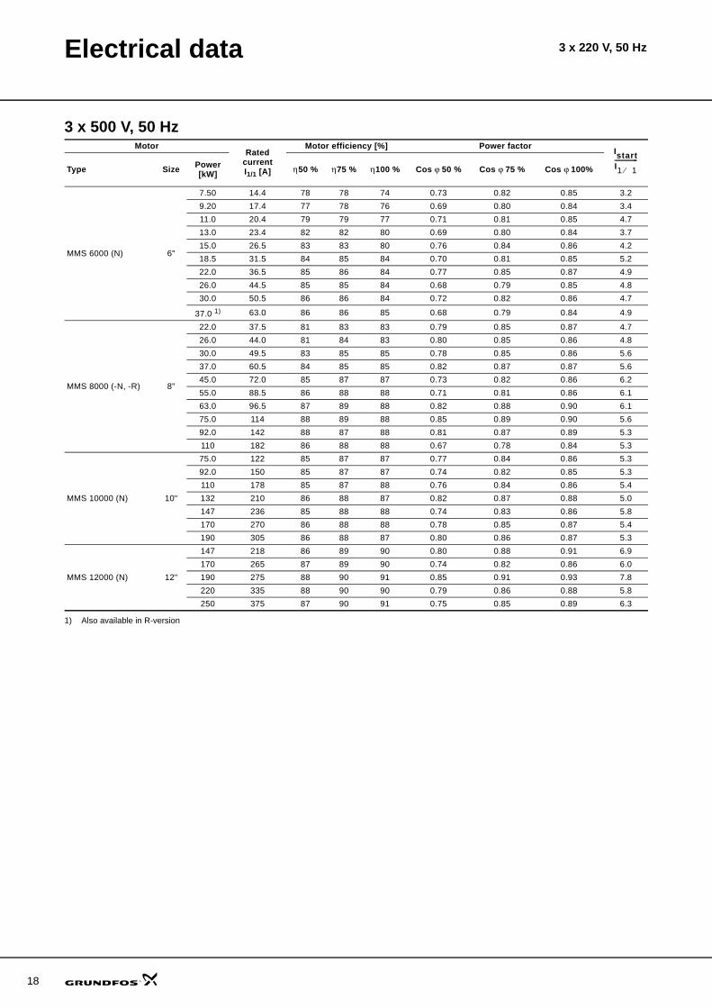
Electrical data 3 x 220 V, 50 Hz
3 x 500 V, 50 Hz
1) Also available in R-version
MotorRated
current I1/1 [A]
Motor efficiency [%] Power factor
Type Size Power[kW] η 50 % η 75 % η 100 % Cos ϕ 50 % Cos ϕ 75 % Cos ϕ 100%
MMS 6000 (N) 6"
7.50 14.4 78 78 74 0.73 0.82 0.85 3.29.20 17.4 77 78 76 0.69 0.80 0.84 3.411.0 20.4 79 79 77 0.71 0.81 0.85 4.713.0 23.4 82 82 80 0.69 0.80 0.84 3.715.0 26.5 83 83 80 0.76 0.84 0.86 4.218.5 31.5 84 85 84 0.70 0.81 0.85 5.222.0 36.5 85 86 84 0.77 0.85 0.87 4.926.0 44.5 85 85 84 0.68 0.79 0.85 4.830.0 50.5 86 86 84 0.72 0.82 0.86 4.7
37.0 1) 63.0 86 86 85 0.68 0.79 0.84 4.9
MMS 8000 (-N, -R) 8"
22.0 37.5 81 83 83 0.79 0.85 0.87 4.726.0 44.0 81 84 83 0.80 0.85 0.86 4.830.0 49.5 83 85 85 0.78 0.85 0.86 5.637.0 60.5 84 85 85 0.82 0.87 0.87 5.645.0 72.0 85 87 87 0.73 0.82 0.86 6.255.0 88.5 86 88 88 0.71 0.81 0.86 6.163.0 96.5 87 89 88 0.82 0.88 0.90 6.175.0 114 88 89 88 0.85 0.89 0.90 5.692.0 142 88 87 88 0.81 0.87 0.89 5.3110 182 86 88 88 0.67 0.78 0.84 5.3
MMS 10000 (N) 10"
75.0 122 85 87 87 0.77 0.84 0.86 5.392.0 150 85 87 87 0.74 0.82 0.85 5.3110 178 85 87 88 0.76 0.84 0.86 5.4132 210 86 88 87 0.82 0.87 0.88 5.0147 236 85 88 88 0.74 0.83 0.86 5.8170 270 86 88 88 0.78 0.85 0.87 5.4190 305 86 88 87 0.80 0.86 0.87 5.3
MMS 12000 (N) 12"
147 218 86 89 90 0.80 0.88 0.91 6.9170 265 87 89 90 0.74 0.82 0.86 6.0190 275 88 90 91 0.85 0.91 0.93 7.8220 335 88 90 90 0.79 0.86 0.88 5.8250 375 87 90 91 0.75 0.85 0.89 6.3
IstartI1 1⁄-------------
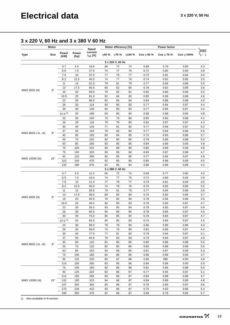
Electrical data 3 x 220 V, 50 Hz
3 x 220 V, 60 Hz and 3 x 380 V 60 Hz
1) Also available in R-version
MotorRated
current I1/1 [A]
Motor efficiency [%] Power factor
Type Size Power[kW]
Power[hp] η 50 % η 75 % η 100 % Cos ϕ 50 % Cos ϕ 75 % Cos ϕ 100%
3 x 220 V, 60 Hz
MMS 6000 (N) 6"
3.7 5.0 19.6 66 72 74 0.68 0.76 0.80 4.35.5 7.5 27.5 74 77 75 0.72 0.80 0.83 3.87.5 10 37.0 77 79 77 0.73 0.81 0.84 3.59.2 12.5 45.0 74 77 76 0.74 0.82 0.85 3.511 15 51.5 79 81 79 0.77 0.84 0.86 3.513 17.5 60.5 80 82 80 0.78 0.82 0.85 3.615 20 69.0 79 82 81 0.82 0.86 0.86 3.5
18.5 25 81.0 82 84 83 0.85 0.88 0.88 4.622 30 96.0 82 84 84 0.84 0.88 0.88 4.926 35 114 83 85 83 0.77 0.84 0.87 4.430 40 130 84 85 84 0.77 0.84 0.87 4.4
37.0 1) 50 166 83 85 84 0.68 0.88 0.84 4.8
MMS 8000 (-N, -R) 8"
22 30 102 75 79 80 0.80 0.85 0.86 4.426 35 118 75 79 80 0.82 0.87 0.87 4.330 40 134 77 81 82 0.77 0.84 0.87 5.237 50 164 78 82 82 0.77 0.84 0.86 5.045 60 192 80 84 85 0.75 0.83 0.86 5.755 75 232 82 85 85 0.79 0.86 0.88 5.363 85 265 83 85 85 0.84 0.89 0.90 4.875 100 315 83 86 85 0.85 0.89 0.90 4.8
MMS 10000 (N) 10"
75 100 320 83 85 84 0.83 0.87 0.88 4.792 125 395 82 85 85 0.77 0.84 0.87 4.9110 150 470 82 85 85 0.85 0.88 0.89 4.5132 180 570 82 85 84 0.86 0.89 0.89 4.2
3 x 380 V, 60 Hz
MMS 6000 (N) 6"
3.7 5.0 11.4 66 72 74 0.69 0.77 0.80 4.25.5 7.5 16.0 74 77 75 0.72 0.80 0.83 3.87.5 10 21.4 77 79 77 0.73 0.81 0.84 3.59.2 12.5 26.0 74 78 76 0.75 0.82 0.85 3.511 15 29.5 79 81 79 0.77 0.84 0.86 3.613 17.5 35.0 80 82 80 0.75 0.82 0.85 3.715 20 40.5 79 82 80 0.78 0.84 0.86 3.5
18.5 25 46.5 82 85 83 0.79 0.85 0.87 4.722 30 55.5 83 85 84 0.78 0.85 0.87 4.926 35 65.5 84 85 84 0.78 0.85 0.87 4.630 40 75.5 84 85 84 0.76 0.84 0.87 4.7
37.0 1) 50 94.5 84 85 83 0.76 0.84 0.87 4.5
MMS 8000 (-N, -R) 8"
22 30 59.0 75 79 80 0.80 0.85 0.86 4.426 35 69.0 75 79 80 0.81 0.86 0.87 4.430 40 77.0 77 81 82 0.78 0.84 0.87 5.137 50 94.0 79 83 83 0.79 0.85 0.87 4.945 60 110 81 85 85 0.80 0.86 0.88 5.555 75 132 82 85 86 0.83 0.88 0.89 5.063 85 152 83 85 85 0.81 0.87 0.89 5.375 100 182 84 86 85 0.86 0.89 0.90 4.792 125 220 85 87 86 0.85 089 0.90 4.8110 150 260 83 86 86 0.84 0.89 0.90 5.0
MMS 10000 (N) 10"
75 100 182 82 85 86 0.81 0.86 0.88 5.092 125 224 82 86 87 0.77 0.84 0.87 5.1110 150 265 83 86 87 0.84 0.88 0.89 4.7132 180 315 84 86 87 0.84 0.88 0.89 4.8147 200 355 83 86 87 0.78 0.85 0.87 5.6170 230 415 83 86 87 0.75 0.83 0.86 5.4190 260 475 82 86 87 0.69 0.79 0.85 5.7
IstartI1 1⁄-------------
19

20
Electrical data 3 x 220 V, 50 Hz
3 x 460 V, 60 Hz and 3 x 575 V, 60 Hz
1) Also available in R-version
MotorRated
current I1/1 [A]
Motor efficiency [%] Power factor
Type Size Power[kW]
Power[hp] η 50 % η 75 % η 100 % Cos ϕ 50 % Cos ϕ 75 % Cos ϕ 100%
3 x 460 V, 60 Hz
MMS 6000 (N) 6"
3.7 5.0 9.75 64 69 70 0.63 0.74 0.80 4.25.5 7.5 13.8 73 76 74 0.63 0.74 0.80 4.07.5 10 18.0 77 79 78 0.61 0.73 0.79 3.89.2 12.5 22.0 74 77 77 0.65 0.76 0.81 3.711 15 25.5 78 80 79 0.65 0.76 0.82 3.813 17.5 29.5 80 82 80 0.65 0.76 0.82 4.015 20 33.5 80 82 81 0.68 0.78 0.83 4.0
18.5 25 39.0 83 85 85 0.65 0.77 0.83 5.522 30 46.0 85 85 85 0.67 0.78 0.83 5.626 35 54.5 84 86 84 0.69 0.80 0.85 5.030 40 62.5 85 86 85 0.68 0.79 0.85 5.1
37.0 1) 50 79.0 84 85 84 0.65 0.75 0.83 4.7
MMS 8000 (-N, -R) 8"
22 30 48.5 75 79 81 0.73 0.81 0.84 5.326 35 56.5 76 80 81 0.77 0.83 0.86 5.130 40 64.0 78 82 83 0.74 0.82 0.85 5.837 50 78.0 80 83 84 0.74 0.82 0.85 5.545 60 92.5 82 85 86 0.71 0.80 0.85 6.455 75 112 82 85 86 0.73 0.82 0.86 5.863 85 126 83 86 86 0.72 0.82 0.86 6.075 100 150 84 86 87 0.72 0.82 0.86 5.792 125 184 85 87 87 0.74 0.83 0.87 6.0110 150 220 84 86 86 0.75 0.83 0.87 5.8
MMS 10000 (N) 10"
75 100 154 81 85 87 0.72 0.80 0.84 5.792 125 190 82 86 87 0.69 0.78 0.83 5.5110 150 224 82 86 88 0.72 0.80 0.84 5.8132 180 265 83 86 88 0.73 0.82 0.85 5.7147 200 305 82 86 87 0.66 0.77 0.82 6.2170 230 355 82 86 87 0.66 0.76 0.82 5.9190 260 405 82 85 87 0.62 0.73 0.79 6.1
3 x 575 V, 60 Hz
MMS 8000 (-N, -R) 8"
22 30 37.5 78 82 83 0.79 0.85 0.87 4.926 35 44.0 78 82 83 0.81 0.85 0.87 5.030 40 49.0 81 84 85 0.79 0.85 0.87 5.837 50 60.5 81 85 85 0.82 0.86 0.88 5.845 60 71.0 84 87 88 0.73 0.82 0.86 6.555 75 86.5 84 87 89 0.72 0.81 0.86 6.563 85 95.5 86 88 89 0.81 0.88 0.90 6.475 100 114 86 89 89 0.84 0.89 0.91 5.892 125 140 87 89 88 0.82 0.87 0.89 5.6110 150 176 85 88 89 0.68 0.79 0.84 5.7
MMS 10000 (N) 10"
75 100 120 82 85 87 0.78 0.84 0.87 6.192 125 148 83 86 87 0.76 0.83 0.86 7.0110 150 176 83 86 87 0.78 0.84 0.87 7.2132 180 208 84 87 87 0.83 0.87 0.88 7.4147 200 234 83 86 88 0.76 0.83 0.86 8.0170 230 270 84 87 88 0.79 0.85 0.87 8.1190 260 300 84 87 88 0.81 0.86 0.87 8.3
IstartI1 1⁄-------------
21
MMSInstallation
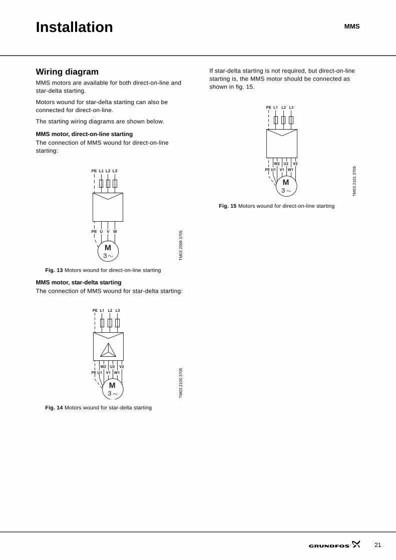
Wiring diagramMMS motors are available for both direct-on-line and star-delta starting.
Motors wound for star-delta starting can also be connected for direct-on-line.
The starting wiring diagrams are shown below.
MMS motor, direct-on-line startingThe connection of MMS wound for direct-on-line starting:
Fig. 13 Motors wound for direct-on-line starting
MMS motor, star-delta startingThe connection of MMS wound for star-delta starting:
Fig. 14 Motors wound for star-delta starting
If star-delta starting is not required, but direct-on-line starting is, the MMS motor should be connected as shown in fig. 15.
Fig. 15 Motors wound for direct-on-line starting
TM03
209
9 37
05TM
03 2
100
3705
L1
PE WVU
PE
M
L3L2
3
L2L1
M
L3PE
W2 U2 V2
PE U1 W1V1
3
TM03
210
1 37
05
L2L1
M
L3PE
W2 U2 V2
PE U1 W1V1
3
22
MMSAccessories
MP 204The MP 204 is an electronic motor protector, designed for the protection of an asynchronous motor or a pump.
The motor protector consists of:
• a cabinet incorporating transformers and electronics• a control panel with operating buttons and display
for reading of data.The MP 204 operates with two sets of limits:
• a set of warning limits and• a set of trip limits.If one or more of the warning limits are exceeded, the motor continues to run, but the warnings will appear in the MP 204 display.
Some values only have a warning limit.
The warning can also be read out by means of the Grundfos R100 remote control.
If one of the trip limits is exceeded, the trip relay will stop the motor. At the same time, the signal relay is operating to indicate that the limit has been exceeded.
ApplicationsThe MP 204 can be used as a stand-alone motor protector.
The MP 204 can be monitored via a Grundfos GENIbus.
The power supply to the MP 204 is in parallel with the supply to the motor. Motor currents up to 120 A are passed directly through the MP 204. The MP 204 protects the motor primarily by measuring the motor current by means of a true RMS measurement. The MP 204 disconnects the contactor if, for example, the current exceeds the preset value.
Secondarily, the pump is protected via temperature measuring by a Tempcon sensor, a Pt100/Pt1000 sensor and a PTC sensor/thermal switch.
The MP 204 is designed for single- and three-phase motors. In single-phase motors, the starting and run capacitors are also measured. Cos ϕ is measured in both single- and three-phase systems.
BenefitsThe MP 204 offers these benefits:
• suitable for both single- and three-phase motors• dry-running protection• overload protection• very high accuracy• made for submersible pumps.
The MP 204 - many monitoring optionsThe MP 204 monitors the following parameters:
• Insulation resistance before start-up• Temperature (Tempcon, Pt sensor and PTC/
thermal switch)• Overload/underload• Overvoltage/undervoltage• Phase sequence• Phase failure• Power factor• Power consumption• Harmonic distortion• Operating hours and number of starts.
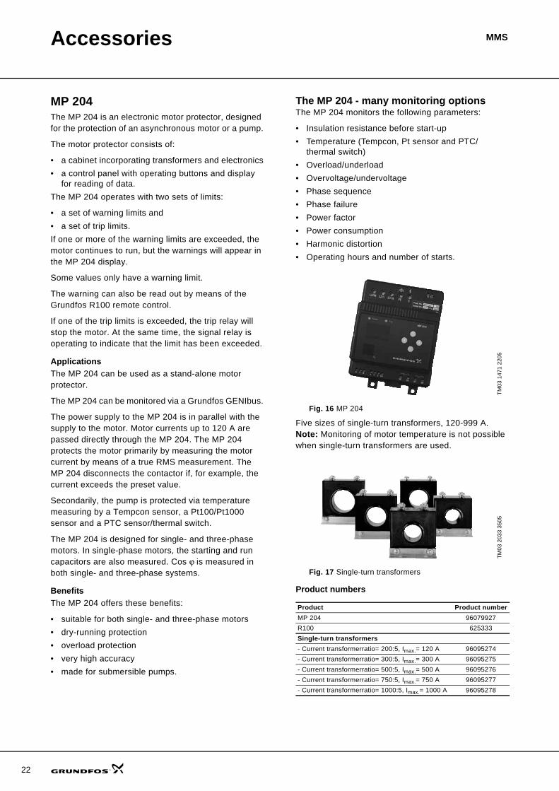
Fig. 16 MP 204
Five sizes of single-turn transformers, 120-999 A. Note: Monitoring of motor temperature is not possible when single-turn transformers are used.
Fig. 17 Single-turn transformers
Product numbers
TM03
147
1 22
05TM
03 2
033
3505
Product Product numberMP 204 96079927R100 625333Single-turn transformers- Current transformerratio= 200:5, Imax.= 120 A 96095274- Current transformerratio= 300:5, Imax.= 300 A 96095275- Current transformerratio= 500:5, Imax.= 500 A 96095276- Current transformerratio= 750:5, Imax.= 750 A 96095277- Current transformerratio= 1000:5, Imax.= 1000 A 96095278
Accessories MMS
Functions• Phase-sequence monitoring• Indication of current or temperature (user selection)• Indication of temperature in °C or °F (user selection)• 4-digit, 7-segment display• Setting and status reading with the R100• Setting and status reading via GENIbus.
Tripping conditions• Overload• Underload (dry running)• Temperature (Tempcon, Pt sensor and PTC/
thermal switch)• Phase failure• Phase sequence• Overvoltage• Undervoltage• Power factor (cos ϕ)• Current unbalance.
Warnings• Overload• Underload• Temperature (Tempcon and Pt sensor)• Overvoltage• Undervoltage• Power factor (cos ϕ)
Note: In connection with single- and three-phase connection.
• Run capacitor (single-phase operation)• Starting capacitor (single-phase operation)• Loss of communication in network• Harmonic distortion.
Learning function• Phase sequence (three-phase operation)• Run capacitor (single-phase operation)• Starting capacitor (single-phase operation)• Identification and measurement of Pt100/Pt1000
sensor circuit.
External current transformersWhen fitted with external current transformers, the MP 204 can handle currents from 120 to 999 A. Grundfos can supply approved current transformers from stock (200/5A, 300/5A, 500/5A, 750/5A, 1000/5A).
R100 remote controlThe R100 remote control from Grundfos allows for wireless infrared remote control of your MP 204 Motor protector.
With the R100, you get access to a full range of options such as factory setting adjustment, service and fault finding.
Ready for bus communicationThe MP 204 allows for monitoring and communication via GENIbus – a Grundfos-designed bus for exchange of pump data, alarms, status information, and setpoints. This enables users to connect the MP 204 to, for instance, SCADA systems.
23

24
Accessories MMS
Technical data - MP 204
Enclosure class IP 20Ambient temperature –20 °C to +60 °CRelative air humidity 99 %Voltage range 100-480 VACCurrent range 3-999 AFrequency 50 to 60 HzIEC trip class 1-45Special Grundfos trip class 0.1 to 30 sVoltage variation – 25 %/+ 15 % of nominal voltageApprovals EN 60947, EN 60335, UL/CSA 508Marking CE, cUL, C-tickConsumption Max. 5 WPlastic type Black PC / ABS
Measuring range Accuracy ResolutionCurrent without external current transformers 3-120 A ± 1 % 0.1 ACurrent with external current transformers 120-999 A ± 1 % 1 APhase-to-phase voltage 80-610 VAC ± 1 % 1 VFrequency 47-63 Hz ± 1 % 0.5 HzPower 0-1 MW ± 2 % 1 WPower factor 0-0.99 ± 2 % 0.01
Energy consumption 0-4x10⁹ kWh ± 5 % 1 kWh
IO 112 Description Product numberThe IO 112 is a measuring module and a 1-channel protection unit for use in connection with the MP 204 motor protection unit. The module can be used for protection of pump against other factors than the electrical conditions, for instance dry-running. It can also be used as a stand-alone protection module.
The IO 112 interface has three inputs for measured values one potentiometer for setting of limits indicator lights indicating the• measured value of the input• value of the limit set• alarm source• pump status.
Electrical data:• Supply voltage: 24 VAC ±10 % 50/60 Hz or 24 VDC ±10 % • Supply current: Min. 2.4 A; max. 8 A• Power consumption:Max. 5 WAmbient temperature: –25 °C to +65 °C• Enclosure class: IP 20
96651601
Accessories MMS
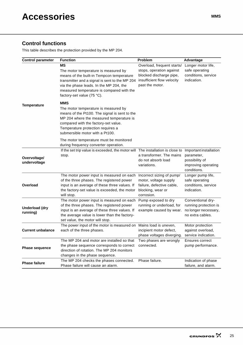
Control functionsThis table describes the protection provided by the MP 204.
Control parameter Function Problem Advantage
Temperature
MSThe motor temperature is measured by means of the built-in Tempcon temperature transmitter and a signal is sent to the MP 204 via the phase leads. In the MP 204, the measured temperature is compared with the factory-set value (75 °C).
MMSThe motor temperature is measured by means of the Pt100. The signal is sent to the MP 204 where the measured temperature is compared with the factory-set value. Temperature protection requires a submersible motor with a Pt100.
The motor temperature must be monitored during frequency converter operation.
Overload, frequent starts/stops, operation against blocked discharge pipe, insufficient flow velocity past the motor.
Longer motor life, safe operating conditions, service indication.
Overvoltage/ undervoltage
If the set trip value is exceeded, the motor will stop.
The installation is close to a transformer. The mains do not absorb load variations.
Important installation parameter, possibility of improving operating conditions.
Overload
The motor power input is measured on each of the three phases. The registered power input is an average of these three values. If the factory-set value is exceeded, the motor will stop.
Incorrect sizing of pump/motor, voltage supply failure, defective cable, blocking, wear or corrosion.
Longer pump life, safe operating conditions, service indication.
Underload (dry running)
The motor power input is measured on each of the three phases. The registered power input is an average of these three values. If the average value is lower than the factory-set value, the motor will stop.
Pump exposed to dry running or underload, for example caused by wear.
Conventional dry-running protection is no longer necessary, no extra cables.
Current unbalance The power input of the motor is measured on each of the three phases.
Mains load is uneven, incipient motor defect, phase voltages diverging.
Motor protection against overload, service indication.
Phase sequence
The MP 204 and motor are installed so that the phase sequence corresponds to correct direction of rotation. The MP 204 monitors changes in the phase sequence.
Two phases are wrongly connected.
Ensures correct pump performance.
Phase failure The MP 204 checks the phases connected. Phase failure will cause an alarm.
Phase failure. Indication of phase failure, and alarm.
25

26
Accessories MMS
R100 menus0. GENERALSee the operating instructions for the R100.
1. OPERATION• Operating mode• Actual trip• Actual warning 1• Actual warning 2• Alarm log 1• Alarm log 2• Alarm log 3• Alarm log 4• Alarm log 5.
2. STATUSDisplay of
• Supply overview• Average current• Average voltage• Tempcon sensor• Pt100/Pt1000 sensor• Power input and energy consumption
(described in the following)• Energy trip counter• Phase sequence• Current unbalance• Operating hours and number of starts• Trip counter of hours and starts• Starting capacitor• Run capacitor• Insulation resistance• Cos ϕ• Harmonic distortion.
3. LIMITSDisplay and setting of warning and trip limits.
• Tempcon sensor• Pt sensor• Tripping current• Current warning• Nominal voltage• Voltage limits• Current unbalance• Starting capacitor• Run capacitor• Insulation resistance• Cos ϕ trip• Cos ϕ warning.
4. INSTALLATIONSetting and display of
• Supply mains• Trip class (described in the following)• Trip delay• External current transformers• Power-on delay• Restarting (described in the following)• Automatic restarting (described in the following)• Tempcon sensor• Pt sensor• Insulation resistance measurement• PTC/hermal switch• Resetting of trip counters• Service interval• Number of automatic restarts• Units/display• MP 204 display• GENIbus ID number• Learning function.
Power input and energy consumption
Actual power input and motor energy consumption.
The energy consumption is an accumulated value which cannot be reset.
The power is calculated like this:
UaverageUL1 L2– UL2 L3– UL3 L1–+ +
3-------------------------------------------------------------------------------------- V[ ]=
IaverageIL1 IL2 IL3+ +
3--------------------------------------- A[ ]=
ϕcos averageϕcos L1 ϕcos L2 ϕcos L3+ +
3--------------------------------------------------------------------------- -[ ]=
P Uaverage Iaverage• 3• ϕcos average• W[ ]=
Accessories MMS
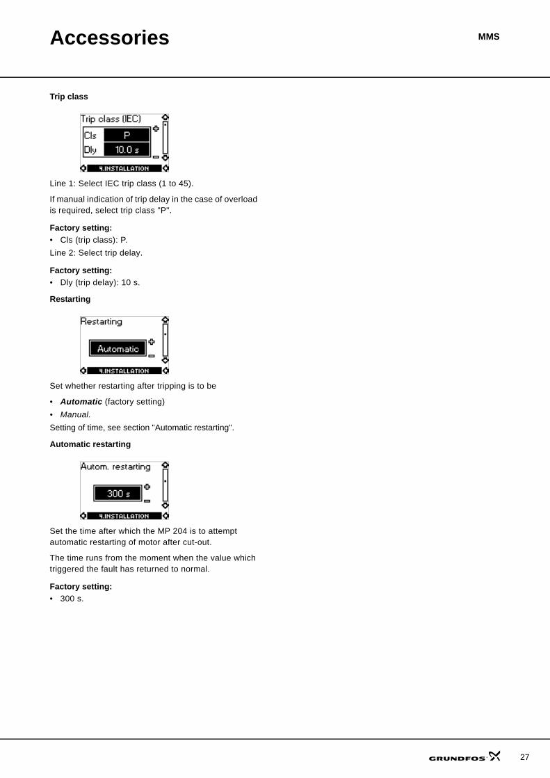
Trip class
Line 1: Select IEC trip class (1 to 45).
If manual indication of trip delay in the case of overload is required, select trip class "P".
Factory setting: • Cls (trip class): P.Line 2: Select trip delay.
Factory setting: • Dly (trip delay): 10 s.
Restarting
Set whether restarting after tripping is to be
• Automatic (factory setting)• Manual.Setting of time, see section "Automatic restarting".
Automatic restarting
Set the time after which the MP 204 is to attempt automatic restarting of motor after cut-out.
The time runs from the moment when the value which triggered the fault has returned to normal.
Factory setting: • 300 s.
27
28
Accessories MMS
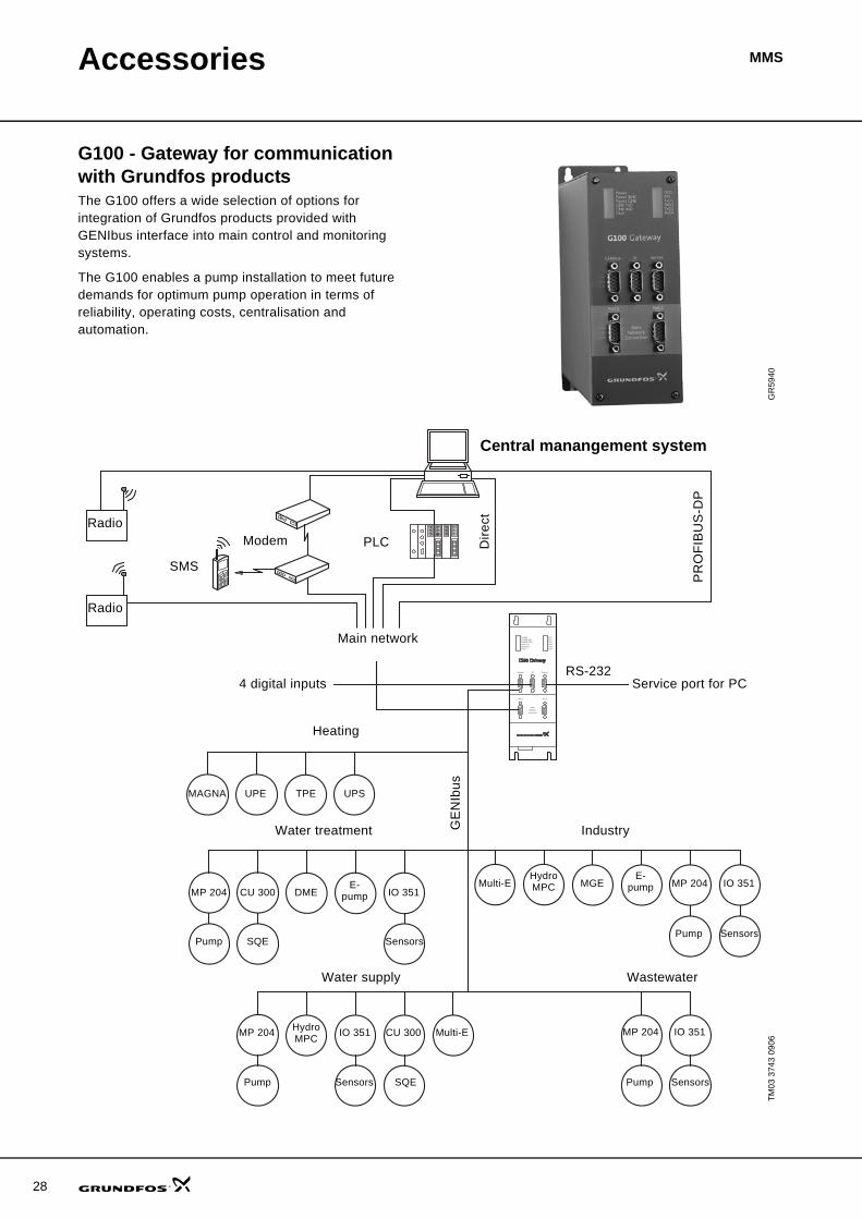
G100 - Gateway for communication with Grundfos productsThe G100 offers a wide selection of options for integration of Grundfos products provided with GENIbus interface into main control and monitoring systems.
The G100 enables a pump installation to meet future demands for optimum pump operation in terms of reliability, operating costs, centralisation and automation.
GR
5940
TM03
374
3 09
06
Port 1
Main
Network
Connection
POWERPOWER MNCPOWER GENIGENI TxDGENI RxDFAULT
DCDRTSTxD1RxD1TxD2RxD2
Port 2
Genibus DI Service
Radio
Radio
SMS
Modem PLC Dire
ct
PR
OFI
BU
S-D
P
Central manangement system
Main network
Service port for PCRS-232
4 digital inputs
Heating
Water treatment IndustryGE
NIb
us
Water supply Wastewater
MAGNA UPE TPE UPS
MP 204 CU 300 DMEE-
pump IO 351
Pump SQE Sensors
Multi-EHydroMPC MGE
E-pump MP 204 IO 351
SensorsPump
MP 204 IO 351
SensorsPump
MP 204 HydroMPC IO 351 CU 300 Multi-E
Pump Sensors SQE

Accessories MMS
Product descriptionThe G100 Gateway enables communication of operating data, such as measured values, setpoints, etc., between Grundfos products with GENIbus interface and a main network for control and monitoring.
As indicated in the illustration on page 28, the G100 is suitable for use in applications such as water supply, water treatment, wastewater, building automation and industry.
Common to the above applications is that downtime is usually costly, and extra investments are therefore often made to achieve maximum reliability by monitoring selected operating variables.
The day-to-day operation, such as starting and stopping of pumps, changing of setpoints, etc., can also be effected from the main system by communication with the G100. In addition, the G100 can be set up to send event-controlled status indications such as alarms via the SMS to mobile phones, and to make automatic alarm call-backs to a central management system.
Data loggingBesides the possibility of data communication, the G100 also offers logging of up to 350,000 time-stamped data. Subsequently, the logged data can be transmitted to the main system or a PC for further analysis in a spreadsheet or similar program.
For the data logging, the "PC Tool G100 Data Log" software tool is used. The tool is part of the PC Tool G100 package, which is included on delivery of the G100.
Other features• Four digital inputs.• Stop of all pumps in case of failing communication
with the management system (optional).• Access code for modem communication (optional).• Alarm log.
InstallationInstallation of the G100 is effected by the system integrator. The G100 is connected to the GENIbus as well as to the main network. Subsequently, all units on the GENIbus can be controlled from a central management system on the main network.
The "G100 Support Files" CD-ROM supplied with the G100 contains examples of programs to be used when the G100 is connected to the various main network systems. Included is also a description of the data points available in Grundfos products with GENIbus interface.
The "PC Tool G100" software tool can be used for the G100 installation and use.
Technical data
Overview of protocols
Other possible connections
Accessories• PC Tool G100 package (supplied with the product)• "G100 Support Files" CD-ROM (supplied with the
product)
Product numbers
TM01
062
1 03
98
Main system Software protocolPROFIBUS-DP DPRadio Satt Control COMLI/ModbusModem Satt Control COMLI/ModbusPLC Satt Control COMLI/ModbusGSM mobile phone SMS, UCP
GENIbus RS-485: Connection of up to 32 unitsService port RS-232: For direct connection to a PC or
via radio modemDigital inputs: 4Voltage supply: 1 x 110-240 V, 50/60 HzAmbient temperature:
In operation: –20 °C to +60 °C
Enclosure class: IP 20Weight: 1.8 kg.
Product Product numberG100 with PROFIBUS-DP expansion board* 96411135G100 with Radio/Modem/PLC-expansion board* 96411136G100 Basic Version 96411137PC Tool G100 package 96415783
CD-ROM with G100 Support Files included.
73 mm 165 mm
227
mm
Port 1
Main
Network
Connection
POWER
POWER MNC
POWER GENI
GENI TxD
GENI RxD
FAULT
DCD
RTS
TxD1
RxD1
TxD2
RxD2
Port 2
Genibus DI Service
29
30
Accessories MMS
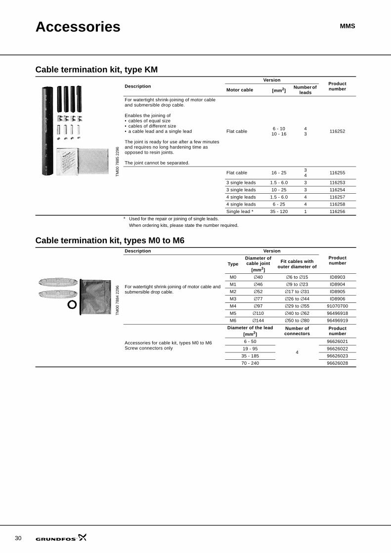
Cable termination kit, type KM
Cable termination kit, types M0 to M6
TM00
788
5 22
96
DescriptionVersion
Product numberMotor cable [mm2]
Number of leads
For watertight shrink-joining of motor cable and submersible drop cable.
Enables the joining of• cables of equal size• cables of different size• a cable lead and a single lead
The joint is ready for use after a few minutes and requires no long hardening time as opposed to resin joints.
The joint cannot be separated.
Flat cable 6 - 1010 - 16
43 116252
Flat cable 16 - 25 34 116255
3 single leads 1.5 - 6.0 3 1162533 single leads 10 - 25 3 1162544 single leads 1.5 - 6.0 4 1162574 single leads 6 - 25 4 116258Single lead * 35 - 120 1 116256
* Used for the repair or joining of single leads.When ordering kits, please state the number required.
TM00
788
4 22
96
Description VersionProduct number
For watertight shrink-joining of motor cable and submersible drop cable.
TypeDiameter of cable joint
[mm2]
Fit cables with outer diameter of
M0 ∅40 ∅6 to ∅15 ID8903M1 ∅46 ∅9 to ∅23 ID8904M2 ∅52 ∅17 to ∅31 ID8905M3 ∅77 ∅26 to ∅44 ID8906M4 ∅97 ∅29 to ∅55 91070700M5 ∅110 ∅40 to ∅62 96496918M6 ∅144 ∅50 to ∅80 96496919
Accessories for cable kit, types M0 to M6Screw connectors only
Diameter of the lead[mm2]
Number of connectors
Product number
6 - 50
4
9662602119 - 95 96626022
35 - 185 9662602370 - 240 96626028
Accessories MMS
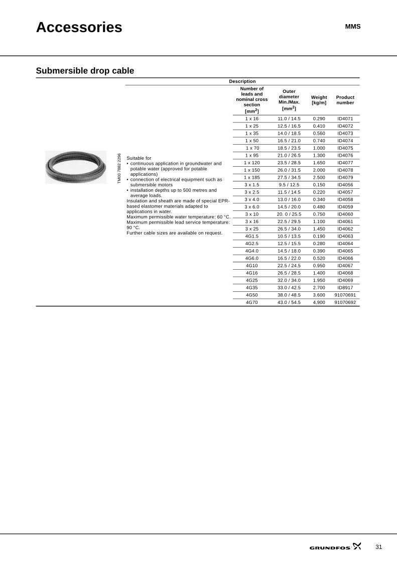
Submersible drop cable
TM00
788
2 22
96
Description
Suitable for • continuous application in groundwater and
potable water (approved for potable applications)
• connection of electrical equipment such as submersible motors
• installation depths up to 500 metres and average loads.
Insulation and sheath are made of special EPR-based elastomer materials adapted to applications in water.Maximum permissible water temperature: 60 °C.Maximum permissible lead service temperature: 90 °C. Further cable sizes are available on request.
Number of leads and
nominal cross section[mm2]
Outer diameterMin./Max.
[mm2]
Weight[kg/m]
Product number
1 x 16 11.0 / 14.5 0.290 ID40711 x 25 12.5 / 16.5 0.410 ID40721 x 35 14.0 / 18.5 0.560 ID40731 x 50 16.5 / 21.0 0.740 ID4074 1 x 70 18.5 / 23.5 1.000 ID40751 x 95 21.0 / 26.5 1.300 ID4076
1 x 120 23.5 / 28.5 1.650 ID40771 x 150 26.0 / 31.5 2.000 ID40781 x 185 27.5 / 34.5 2.500 ID40793 x 1.5 9.5 / 12.5 0.150 ID40563 x 2.5 11.5 / 14.5 0.220 ID40573 x 4.0 13.0 / 16.0 0.340 ID40583 x 6.0 14.5 / 20.0 0.480 ID40593 x 10 20. 0 / 25.5 0.750 ID40603 x 16 22.5 / 29.5 1.100 ID40613 x 25 26.5 / 34.0 1.450 ID40624G1.5 10.5 / 13.5 0.190 ID40634G2.5 12.5 / 15.5 0.280 ID40644G4.0 14.5 / 18.0 0.390 ID40654G6.0 16.5 / 22.0 0.520 ID40664G10 22.5 / 24.5 0.950 ID40674G16 26.5 / 28.5 1.400 ID40684G25 32.0 / 34.0 1.950 ID40694G35 33.0 / 42.5 2.700 ID89174G50 38.0 / 48.5 3.600 910706914G70 43.0 / 54.5 4.900 91070692
31
32
Accessories MMS
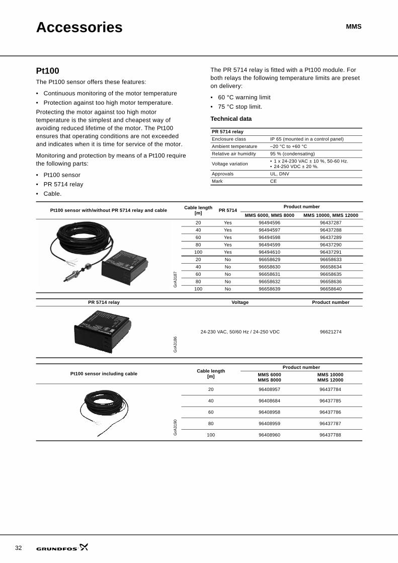
Pt100The Pt100 sensor offers these features:
• Continuous monitoring of the motor temperature• Protection against too high motor temperature.Protecting the motor against too high motor temperature is the simplest and cheapest way of avoiding reduced lifetime of the motor. The Pt100 ensures that operating conditions are not exceeded and indicates when it is time for service of the motor.
Monitoring and protection by means of a Pt100 require the following parts:
• Pt100 sensor• PR 5714 relay• Cable.
The PR 5714 relay is fitted with a Pt100 module. For both relays the following temperature limits are preset on delivery:
• 60 °C warning limit• 75 °C stop limit.
Technical data
PR 5714 relayEnclosure class IP 65 (mounted in a control panel)Ambient temperature –20 °C to +60 °CRelative air humidity 95 % (condensating)
Voltage variation • 1 x 24-230 VAC ± 10 %, 50-60 Hz.• 24-250 VDC ± 20 %.
Approvals UL, DNVMark CE
Pt100 sensor with/without PR 5714 relay and cable Cable length [m] PR 5714
Product number
MMS 6000, MMS 8000 MMS 10000, MMS 12000
GrA
3187
20 Yes 96494596 9643728740 Yes 96494597 9643728860 Yes 96494598 9643728980 Yes 96494599 96437290
100 Yes 96494610 9643729120 No 96658629 9665863340 No 96658630 9665863460 No 96658631 9665863580 No 96658632 96658636
100 No 96658639 96658640
PR 5714 relay Voltage Product number
GrA
3186
24-230 VAC, 50/60 Hz / 24-250 VDC 96621274
Pt100 sensor including cable Cable length[m]
Product numberMMS 6000MMS 8000
MMS 10000MMS 12000
GrA
3190
20 96408957 96437784
40 96408684 96437785
60 96408958 96437786
80 96408959 96437787
100 96408960 96437788

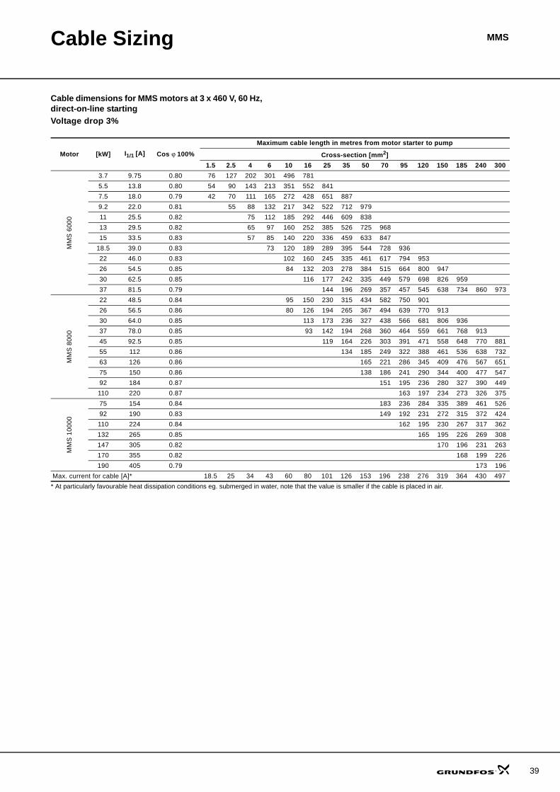
MMSCable Sizing
Drop cablesGrundfos offers submersible drop cables for all types of applications, i.e. 3-core cables, 4-core cables, single leads.
The choice of submersible drop cable depends on the application and type of installation.
Standard version: Maximum liquid temperature +60 °C.
Tables indicating cable dimensions in boreholeThe tables indicate the maximum length of drop cables in metres from motor starter to pump at direct-on-line starting, and at different cable dimensions.
The lengths of the cables are calculated by means of the maximum current for cables according to IEC 364 and HD 384.
If, for example, the operating current is 10% lower than the rated current, the cable may be 10% longer than indicated in the table.
The calculation of the cable length is based on a maximum voltage drop of 3% of the rated voltage and a water temperature of maximum 30 °C.
To minimise operating losses, the cable cross- section may be increased compared to what is indicated in the table. This is economical only if:
• the borehole provides the necessary space• the operating time of the pump is long or• the operating voltage is below the rated voltage.The table values are calculated on the basis of the following formula:
Maximum cable length of a three-phase submersible pump:
where
U = Rated voltage [V]
ΔU = Voltage drop [%]
I = Rated current of the motor [A]
q = Cross-section of submersible dropcable [mm2]
XL = Inductive resistance: 0.078 x 10⁻³ [Ω/m]
cos ϕ = Power factor
sin ϕ =
ρ = Specific resistance: 0.02 [Ωmm2/m]
Example
Motor size: 30 kW, MMS 8000Rated current: 64.0 ARated voltage: 3 x 400 V, 50 HzStarting method: Direct-on-linePower factor: cosϕ = 0.85Voltage drop: 3%Cross-section: 25 mm2
sin ϕ: 0.54
L = 150 m.
L U ΔU×
I 1.73× 100× ϕcos ρq--- ϕsin XL×+×⎝ ⎠
⎛ ⎞×------------------------------------------------------------------------------------------------------------ m ][=
1 ϕcos2–
L 400 3×
64.0 1.73× 100× 0.85 0.0225
-----------× 0.54 0.078 103–
××+⎝ ⎠⎛ ⎞×
--------------------------------------------------------------------------------------------------------------------------------------------------------=
33
34
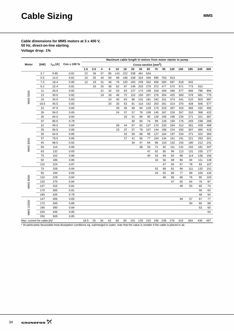
Cable Sizing MMS
Cable dimensions for MMS motors at 3 x 400 V, 50 Hz, direct-on-line startingVoltage drop: 1%
Motor [kW] I1/1 [A] Cos ϕ 100 %Maximum cable length in metres from motor starter to pump
Cross-section [mm2]1.5 2.5 4 6 10 16 25 35 50 70 95 120 150 185 240 300
MM
S 6
000
3.7 9.85 0.81 22 36 57 85 141 222 338 461 634 5.5 14.0 0.81 15 25 40 60 99 156 238 324 446 595 763 913 7.5 18.4 0.80 12 19 31 46 76 120 183 249 342 456 583 697 818 942 9.2 22.4 0.81 16 25 38 62 97 149 203 279 372 477 570 671 773 910 11 26.0 0.82 21 32 53 83 127 173 238 318 409 490 577 666 786 894 13 30.0 0.82 19 28 46 72 110 150 207 276 354 425 500 578 681 775 15 34.0 0.83 24 40 63 96 131 181 242 311 374 441 510 603 687
18.5 40.5 0.83 20 33 53 81 110 152 203 261 314 370 428 506 577 22 47.5 0.83 29 45 69 94 129 173 223 267 315 365 432 492 26 56.0 0.85 24 37 57 78 108 145 187 226 267 310 368 422 30 64.0 0.84 33 51 69 95 128 165 198 234 271 321 367 37 85.5 0.79 40 54 74 99 126 150 176 203 238 269
MM
S 8
000
22 48.0 0.84 28 44 67 92 127 170 220 264 312 361 428 489 26 56.5 0.85 23 37 57 78 107 144 186 224 265 307 365 418 30 64.0 0.85 33 50 68 95 127 164 197 234 271 322 369 37 78.5 0.85 27 41 56 77 104 134 161 191 221 263 301 45 96.5 0.82 34 47 64 86 110 132 155 180 212 241 55 114 0.85 38 53 71 92 111 131 152 181 207 63 132 0.83 47 62 80 96 113 131 155 177 75 152 0.86 40 53 69 83 98 114 136 156 92 186 0.86 43 56 68 80 94 111 128 110 224 0.87 47 56 67 78 93 107
MM
S 8
000
75 156 0.84 52 68 81 96 111 132 151 92 194 0.82 43 55 66 77 89 105 120 110 228 0.84 46 56 66 76 90 103 132 270 0.84 47 55 64 76 87 147 315 0.81 48 55 65 74 170 365 0.81 56 63 190 425 0.79 48 54
MM
S 1
2000
147 305 0.83 49 57 67 77 170 345 0.85 50 60 68 190 390 0.84 53 60 220 445 0.85 53 250 505 0.85
Max. current for cable [A]* 18.5 25 34 43 60 80 101 126 153 196 238 276 319 364 430 497* At particularly favourable heat dissipation conditions eg. submerged in water, note that the value is smaller if the cable is placed in air.
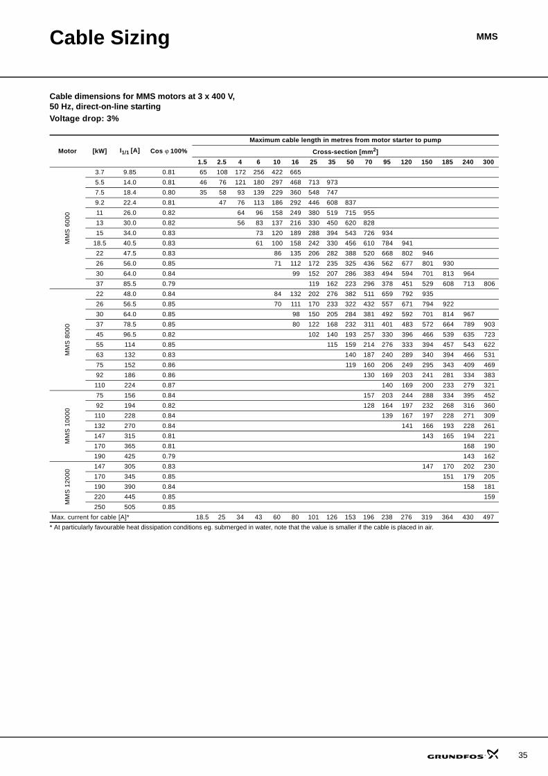
Cable Sizing MMS
Cable dimensions for MMS motors at 3 x 400 V, 50 Hz, direct-on-line startingVoltage drop: 3%
Motor [kW] I1/1 [A] Cos ϕ 100%Maximum cable length in metres from motor starter to pump
Cross-section [mm2]1.5 2.5 4 6 10 16 25 35 50 70 95 120 150 185 240 300
MM
S 6
000
3.7 9.85 0.81 65 108 172 256 422 665 5.5 14.0 0.81 46 76 121 180 297 468 713 973 7.5 18.4 0.80 35 58 93 139 229 360 548 747 9.2 22.4 0.81 47 76 113 186 292 446 608 837 11 26.0 0.82 64 96 158 249 380 519 715 955 13 30.0 0.82 56 83 137 216 330 450 620 828 15 34.0 0.83 73 120 189 288 394 543 726 934
18.5 40.5 0.83 61 100 158 242 330 456 610 784 941 22 47.5 0.83 86 135 206 282 388 520 668 802 946 26 56.0 0.85 71 112 172 235 325 436 562 677 801 930 30 64.0 0.84 99 152 207 286 383 494 594 701 813 964 37 85.5 0.79 119 162 223 296 378 451 529 608 713 806
MM
S 8
000
22 48.0 0.84 84 132 202 276 382 511 659 792 935 26 56.5 0.85 70 111 170 233 322 432 557 671 794 922 30 64.0 0.85 98 150 205 284 381 492 592 701 814 967 37 78.5 0.85 80 122 168 232 311 401 483 572 664 789 903 45 96.5 0.82 102 140 193 257 330 396 466 539 635 723 55 114 0.85 115 159 214 276 333 394 457 543 622 63 132 0.83 140 187 240 289 340 394 466 531 75 152 0.86 119 160 206 249 295 343 409 469 92 186 0.86 130 169 203 241 281 334 383 110 224 0.87 140 169 200 233 279 321
MM
S 1
0000
75 156 0.84 157 203 244 288 334 395 452 92 194 0.82 128 164 197 232 268 316 360 110 228 0.84 139 167 197 228 271 309 132 270 0.84 141 166 193 228 261 147 315 0.81 143 165 194 221 170 365 0.81 168 190 190 425 0.79 143 162
MM
S 1
2000
147 305 0.83 147 170 202 230 170 345 0.85 151 179 205 190 390 0.84 158 181 220 445 0.85 159 250 505 0.85
Max. current for cable [A]* 18.5 25 34 43 60 80 101 126 153 196 238 276 319 364 430 497* At particularly favourable heat dissipation conditions eg. submerged in water, note that the value is smaller if the cable is placed in air.
35
36
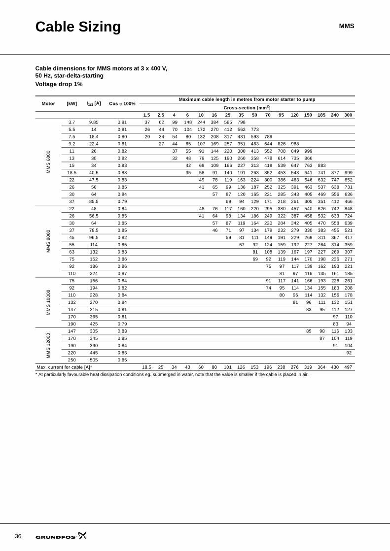
Cable Sizing MMS
Cable dimensions for MMS motors at 3 x 400 V, 50 Hz, star-delta-startingVoltage drop 1%
Motor [kW] I1/1 [A] Cos ϕ 100%Maximum cable length in metres from motor starter to pump
Cross-section [mm2]1.5 2.5 4 6 10 16 25 35 50 70 95 120 150 185 240 300
MM
S 6
000
3.7 9.85 0.81 37 62 99 148 244 384 585 798 5.5 14 0.81 26 44 70 104 172 270 412 562 773 7.5 18.4 0.80 20 34 54 80 132 208 317 431 593 789 9.2 22.4 0.81 27 44 65 107 169 257 351 483 644 826 988 11 26 0.82 37 55 91 144 220 300 413 552 708 849 999 13 30 0.82 32 48 79 125 190 260 358 478 614 735 866 15 34 0.83 42 69 109 166 227 313 419 539 647 763 883
18.5 40.5 0.83 35 58 91 140 191 263 352 453 543 641 741 877 999 22 47.5 0.83 49 78 119 163 224 300 386 463 546 632 747 852 26 56 0.85 41 65 99 136 187 252 325 391 463 537 638 731 30 64 0.84 57 87 120 165 221 285 343 405 469 556 636 37 85.5 0.79 69 94 129 171 218 261 305 351 412 466
MM
S 8
000
22 48 0.84 48 76 117 160 220 295 380 457 540 626 742 848 26 56.5 0.85 41 64 98 134 186 249 322 387 458 532 633 724 30 64 0.85 57 87 119 164 220 284 342 405 470 558 639 37 78.5 0.85 46 71 97 134 179 232 279 330 383 455 521 45 96.5 0.82 59 81 111 149 191 229 269 311 367 417 55 114 0.85 67 92 124 159 192 227 264 314 359 63 132 0.83 81 108 139 167 197 227 269 307 75 152 0.86 69 92 119 144 170 198 236 271 92 186 0.86 75 97 117 139 162 193 221 110 224 0.87 81 97 116 135 161 185
MM
S 1
0000
75 156 0.84 91 117 141 166 193 228 261 92 194 0.82 74 95 114 134 155 183 208 110 228 0.84 80 96 114 132 156 178 132 270 0.84 81 96 111 132 151 147 315 0.81 83 95 112 127 170 365 0.81 97 110 190 425 0.79 83 94
MM
S 1
2000
147 305 0.83 85 98 116 133 170 345 0.85 87 104 119 190 390 0.84 91 104 220 445 0.85 92 250 505 0.85
Max. current for cable [A]* 18.5 25 34 43 60 80 101 126 153 196 238 276 319 364 430 497* At particularly favourable heat dissipation conditions eg. submerged in water, note that the value is smaller if the cable is placed in air.

Cable Sizing MMS
Cable dimensions for MMS motors at 3 x 400 V, 50 Hz, star-delta startingVoltage drop 3%
Motor [kW] I1/1 [A] Cos ϕ 100%Maximum cable length in metres from motor starter to pump
Cross-section [mm2]1.5 2.5 4 6 10 16 25 35 50 70 95 120 150 185 240 300
MM
S 6
000
3.7 9.85 0.81 112 187 297 444 731 5.5 14 0.81 79 131 209 312 515 810 7.5 18.4 0.80 61 101 161 240 396 623 950 9.2 22.4 0.81 82 131 195 322 506 772 11 26 0.82 111 166 274 431 659 899 13 30 0.82 97 144 237 374 571 779 15 34 0.83 126 207 326 499 682 940
18.5 40.5 0.83 105 174 274 419 572 789 22 47.5 0.83 148 234 357 488 673 900 26 56 0.85 123 194 297 407 562 755 974 30 64 0.84 172 262 359 496 664 856 37 85.5 0.79 206 281 386 513 655 782 916
MM
S 8
000
22 48 0.84 145 229 350 479 661 886 26 56.5 0.85 122 192 295 403 557 748 965 30 64 0.85 170 260 356 492 660 852 37 78.5 0.85 139 212 290 401 538 695 836 990 45 96.5 0.82 177 242 334 446 572 686 808 933 55 114 0.85 200 276 371 478 576 682 792 941 63 132 0.83 242 324 417 500 590 682 807 920 75 152 0.86 206 277 357 431 511 595 708 813 92 186 0.86 226 292 352 418 486 579 664 110 224 0.87 242 292 347 404 483 555
MM
S 1
0000
75 156 0.84 272 351 422 498 578 685 782 92 194 0.82 222 285 341 402 464 548 623 110 228 0.84 240 289 341 395 469 535 132 270 0.84 244 288 334 396 452 147 315 0.81 248 286 336 382 170 365 0.81 290 330 190 425 0.79 248 281
MM
S 1
2000
147 305 0.83 255 295 349 398 170 345 0.85 262 311 356 190 390 0.84 274 313 220 445 0.85 276 250 505 0.85
Max. current for cable [A]* 18.5 25 34 43 60 80 101 126 153 196 238 276 319 364 430 497* At particularly favourable heat dissipation conditions eg. submerged in water, note that the value is smaller if the cable is placed in air.
37

38
Cable Sizing MMS
Cable dimensions for MMS motors at 3 x 460 V, 60 Hz, direct-on-line startingVoltage drop 1%
Motor [kW] I1/1 [A] Cos ϕ 100%Maximum cable length in metres from motor starter to pump
Cross-section [mm2]1.5 2.5 4 6 10 16 25 35 50 70 95 120 150 185 240 300
MM
S 6
000
3.7 9.75 0.80 25 42 67 100 165 260 397 541 743 989 5.5 13.8 0.80 18 30 48 71 117 184 280 382 525 699 894 7.5 18.0 0.79 14 23 37 55 91 143 217 296 406 539 689 822 963 9.2 22.0 0.81 18 29 44 72 114 174 237 326 436 558 668 785 906 11 25.5 0.82 25 37 62 97 149 203 279 373 479 574 676 781 922 13 29.5 0.82 22 32 53 84 128 175 242 323 414 497 585 675 797 907 15 33.5 0.83 19 28 47 73 112 153 211 282 363 436 514 595 704 802
18.5 39.0 0.83 24 40 63 96 132 181 243 312 374 442 511 604 689 22 46.0 0.83 34 53 82 112 154 206 265 318 374 433 512 584 26 54.5 0.85 28 44 68 93 128 172 221 267 316 366 435 498 30 62.5 0.85 39 59 81 112 150 193 233 275 320 380 435 37 81.5 0.79 48 65 90 119 152 182 213 245 287 324
MM
S 8
000
22 48.5 0.84 32 50 77 105 145 194 250 300 355 411 488 557 26 56.5 0.86 27 42 65 88 122 165 213 257 304 354 422 484 30 64.0 0.85 38 58 79 109 146 189 227 269 312 371 424 37 78.0 0.85 31 47 65 89 120 155 186 220 256 304 348 45 92.5 0.85 40 55 75 101 130 157 186 216 257 294 55 112 0.86 45 62 83 107 129 154 179 213 244 63 126 0.86 55 74 95 115 136 159 189 217 75 150 0.86 46 62 80 97 115 133 159 182 92 184 0.87 50 65 79 93 109 130 150 110 220 0.87 54 66 78 91 109 125
MM
S 1
0000
75 154 0.84 61 79 95 112 130 154 175 92 190 0.83 50 64 77 91 105 124 141 110 224 0.84 54 65 77 89 106 121 132 265 0.85 55 65 75 90 103 147 305 0.82 57 65 77 88 170 355 0.82 56 66 75 190 405 0.79 58 65
Max. current for cable [A]* 18.5 25 34 43 60 80 101 126 153 196 238 276 319 364 430 497* At particularly favourable heat dissipation conditions eg. submerged in water, note that the value is smaller if the cable is placed in air.
Cable Sizing MMS
Cable dimensions for MMS motors at 3 x 460 V, 60 Hz, direct-on-line startingVoltage drop 3%
Motor [kW] I1/1 [A] Cos ϕ 100%Maximum cable length in metres from motor starter to pump
Cross-section [mm2]1.5 2.5 4 6 10 16 25 35 50 70 95 120 150 185 240 300
MM
S 6
000
3.7 9.75 0.80 76 127 202 301 496 781 5.5 13.8 0.80 54 90 143 213 351 552 841 7.5 18.0 0.79 42 70 111 165 272 428 651 887 9.2 22.0 0.81 55 88 132 217 342 522 712 979 11 25.5 0.82 75 112 185 292 446 609 838 13 29.5 0.82 65 97 160 252 385 526 725 968 15 33.5 0.83 57 85 140 220 336 459 633 847
18.5 39.0 0.83 73 120 189 289 395 544 728 936 22 46.0 0.83 102 160 245 335 461 617 794 953 26 54.5 0.85 84 132 203 278 384 515 664 800 947 30 62.5 0.85 116 177 242 335 449 579 698 826 959 37 81.5 0.79 144 196 269 357 457 545 638 734 860 973
MM
S 8
000
22 48.5 0.84 95 150 230 315 434 582 750 901 26 56.5 0.86 80 126 194 265 367 494 639 770 913 30 64.0 0.85 113 173 236 327 438 566 681 806 936 37 78.0 0.85 93 142 194 268 360 464 559 661 768 913 45 92.5 0.85 119 164 226 303 391 471 558 648 770 881 55 112 0.86 134 185 249 322 388 461 536 638 732 63 126 0.86 165 221 286 345 409 476 567 651 75 150 0.86 138 186 241 290 344 400 477 547 92 184 0.87 151 195 236 280 327 390 449 110 220 0.87 163 197 234 273 326 375
MM
S 1
0000
75 154 0.84 183 236 284 335 389 461 526 92 190 0.83 149 192 231 272 315 372 424 110 224 0.84 162 195 230 267 317 362 132 265 0.85 165 195 226 269 308 147 305 0.82 170 196 231 263 170 355 0.82 168 199 226 190 405 0.79 173 196
Max. current for cable [A]* 18.5 25 34 43 60 80 101 126 153 196 238 276 319 364 430 497* At particularly favourable heat dissipation conditions eg. submerged in water, note that the value is smaller if the cable is placed in air.
39
40
Cable Sizing MMS
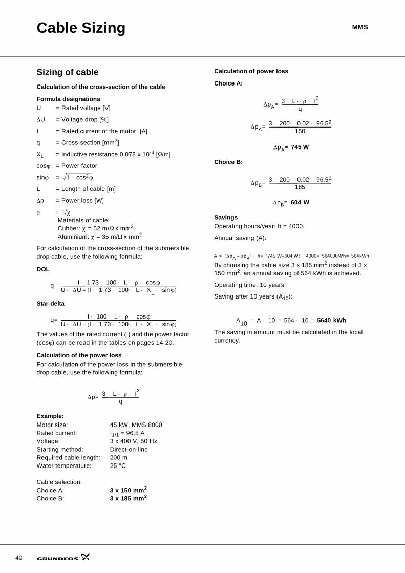
Sizing of cableCalculation of the cross-section of the cable
Formula designationsU = Rated voltage [V]
ΔU = Voltage drop [%]
I = Rated current of the motor [A]
q = Cross-section [mm2]
XL = Inductive resistance 0.078 x 10⁻³ [Ω/m]
cosϕ = Power factor
sinϕ =
L = Length of cable [m]
Δp = Power loss [W]
ρ = 1/χ Materials of cable: Cubber: χ = 52 m/Ω x mm2
Aluminium: χ = 35 m/Ω x mm2
For calculation of the cross-section of the submersible drop cable, use the following formula:
DOL
Star-delta
The values of the rated current (I) and the power factor (cosϕ) can be read in the tables on pages 14-20.
Calculation of the power lossFor calculation of the power loss in the submersible drop cable, use the following formula:
Example:Motor size: 45 kW, MMS 8000Rated current: I1/1 = 96.5 AVoltage: 3 x 400 V, 50 HzStarting method: Direct-on-lineRequired cable length: 200 mWater temperature: 25 °C
Cable selection:Choice A: 3 x 150 mm2
Choice B: 3 x 185 mm2
Calculation of power loss
Choice A:
Choice B:
SavingsOperating hours/year: h = 4000.
Annual saving (A):
By choosing the cable size 3 x 185 mm2 instead of 3 x 150 mm2, an annual saving of 564 kWh is achieved.
Operating time: 10 years
Saving after 10 years (A10):
The saving in amount must be calculated in the local currency.
1 ϕcos2–
q I 1.73 100 L ρ ϕcos⋅ ⋅ ⋅ ⋅ ⋅U ΔU I 1.73 100 L XL ϕsin⋅ ⋅ ⋅ ⋅ ⋅( )–⋅-----------------------------------------------------------------------------------------------------------------=
q I 100 L ρ ϕcos⋅ ⋅ ⋅ ⋅U ΔU I 1.73 100 L XL ϕsin⋅ ⋅ ⋅ ⋅ ⋅( )–⋅-----------------------------------------------------------------------------------------------------------------=
Δp 3 L ρ I2⋅ ⋅ ⋅q
------------------------------------=
ΔpA3 L ρ I2⋅ ⋅ ⋅
q------------------------------------=
ΔpA3 200 0.02 96.52⋅ ⋅ ⋅
150-------------------------------------------------------------=
ΔpA 745 W=
ΔpB3 200 0.02 96.52⋅ ⋅ ⋅
185-------------------------------------------------------------=
ΔpB 604 W=
A ΔpA ΔpB–( ) h 745 W 604 W–( ) 4000 564000Wh 564kWh==⋅=⋅=
A10 A 10 564 10 5640 kWh=⋅=⋅=
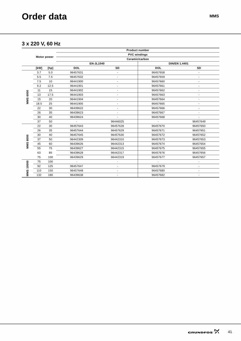
MMSOrder data
3 x 220 V, 60 Hz
Motor power
Product numberPVC windings
Ceramic/carbonEN-JL1040 DIN/EN 1.4401
[kW] [hp] DOL SD DOL SD
MM
S 60
00
3.7 5.0 96457631 - 96457658 -5.5 7.5 96457632 - 96457659 -7.5 10 96441900 - 96457660 -9.2 12.5 96441901 - 96457661 -11 15 96441902 - 96457662 -13 17.5 96441903 - 96457663 -15 20 96441904 - 96457664 -
18.5 25 96441905 - 96457665 -22 30 96439622 - 96457666 -26 35 96439623 - 96457667 -30 40 96439624 - 96457668 -37 50 - 96446025 - 96457649
MM
S 80
00
22 30 96457643 96457628 96457670 9645765026 35 96457644 96457629 96457671 9645765130 40 96457645 96457630 96457672 9645765237 50 96442309 96442310 96457673 9645765345 60 96439626 96442313 96457674 9645765455 75 96439627 96442315 96457675 9645765563 85 96439628 96442317 96457676 9645765675 100 96439629 96442319 96457677 96457657
MM
S 10
000 75 100 - - - -
92 125 96457647 - 96457679 -110 150 96457648 - 96457680 -132 180 96439638 - 96457682 -
41
42
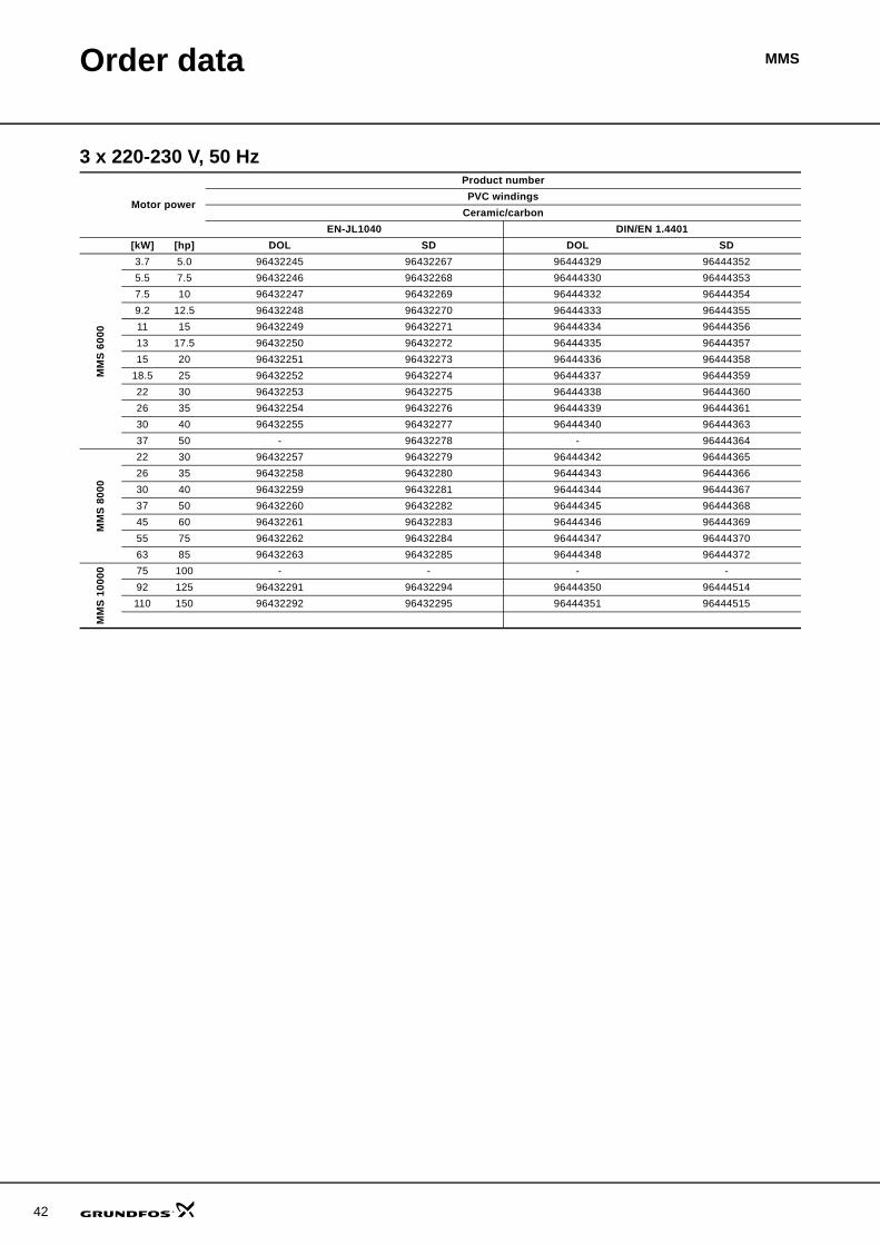
Order data MMS
3 x 220-230 V, 50 Hz
Motor power
Product numberPVC windings
Ceramic/carbonEN-JL1040 DIN/EN 1.4401
[kW] [hp] DOL SD DOL SD
MM
S 60
00
3.7 5.0 96432245 96432267 96444329 964443525.5 7.5 96432246 96432268 96444330 964443537.5 10 96432247 96432269 96444332 964443549.2 12.5 96432248 96432270 96444333 9644435511 15 96432249 96432271 96444334 9644435613 17.5 96432250 96432272 96444335 9644435715 20 96432251 96432273 96444336 96444358
18.5 25 96432252 96432274 96444337 9644435922 30 96432253 96432275 96444338 9644436026 35 96432254 96432276 96444339 9644436130 40 96432255 96432277 96444340 9644436337 50 - 96432278 - 96444364
MM
S 80
00
22 30 96432257 96432279 96444342 9644436526 35 96432258 96432280 96444343 9644436630 40 96432259 96432281 96444344 9644436737 50 96432260 96432282 96444345 9644436845 60 96432261 96432283 96444346 9644436955 75 96432262 96432284 96444347 9644437063 85 96432263 96432285 96444348 96444372
MM
S 10
000 75 100 - - - -
92 125 96432291 96432294 96444350 96444514110 150 96432292 96432295 96444351 96444515
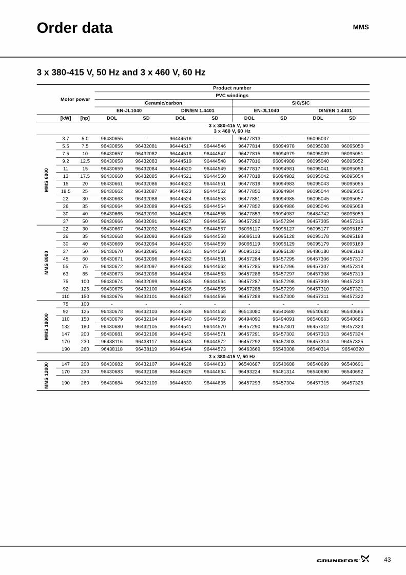
Order data MMS
3 x 380-415 V, 50 Hz and 3 x 460 V, 60 Hz
Motor power
Product numberPVC windings
Ceramic/carbon SiC/SiCEN-JL1040 DIN/EN 1.4401 EN-JL1040 DIN/EN 1.4401
[kW] [hp] DOL SD DOL SD DOL SD DOL SD3 x 380-415 V, 50 Hz
3 x 460 V, 60 Hz
MM
S 60
00
3.7 5.0 96430655 - 96444516 - 96477813 - 96095037 -5.5 7.5 96430656 96432081 96444517 96444546 96477814 96094978 96095038 960950507.5 10 96430657 96432082 96444518 96444547 96477815 96094979 96095039 960950519.2 12.5 96430658 96432083 96444519 96444548 96477816 96094980 96095040 9609505211 15 96430659 96432084 96444520 96444549 96477817 96094981 96095041 9609505313 17.5 96430660 96432085 96444521 96444550 96477818 96094982 96095042 9609505415 20 96430661 96432086 96444522 96444551 96477819 96094983 96095043 96095055
18.5 25 96430662 96432087 96444523 96444552 96477850 96094984 96095044 9609505622 30 96430663 96432088 96444524 96444553 96477851 96094985 96095045 9609505726 35 96430664 96432089 96444525 96444554 96477852 96094986 96095046 9609505830 40 96430665 96432090 96444526 96444555 96477853 96094987 96484742 9609505937 50 96430666 96432091 96444527 96444556 96457282 96457294 96457305 96457316
MM
S 80
00
22 30 96430667 96432092 96444528 96444557 96095117 96095127 96095177 9609518726 35 96430668 96432093 96444529 96444558 96095118 96095128 96095178 9609518830 40 96430669 96432094 96444530 96444559 96095119 96095129 96095179 9609518937 50 96430670 96432095 96444531 96444560 96095120 96095130 96486180 9609519045 60 96430671 96432096 96444532 96444561 96457284 96457295 96457306 9645731755 75 96430672 96432097 96444533 96444562 96457285 96457296 96457307 9645731863 85 96430673 96432098 96444534 96444563 96457286 96457297 96457308 9645731975 100 96430674 96432099 96444535 96444564 96457287 96457298 96457309 9645732092 125 96430675 96432100 96444536 96444565 96457288 96457299 96457310 96457321110 150 96430676 96432101 96444537 96444566 96457289 96457300 96457311 96457322
MM
S 10
000
75 100 - - - - - - - -92 125 96430678 96432103 96444539 96444568 96513080 96540680 96540682 96540685110 150 96430679 96432104 96444540 96444569 96494090 96494091 96540683 96540686132 180 96430680 96432105 96444541 96444570 96457290 96457301 96457312 96457323147 200 96430681 96432106 96444542 96444571 96457291 96457302 96457313 96457324170 230 96438116 96438117 96444543 96444572 96457292 96457303 96457314 96457325190 260 96438118 96438119 96444544 96444573 96463669 96540308 96540314 96540320
3 x 380-415 V, 50 Hz
MM
S 12
000 147 200 96430682 96432107 96444628 96444633 96540687 96540688 96540689 96540691
170 230 96430683 96432108 96444629 96444634 96493224 96481314 96540690 96540692
190 260 96430684 96432109 96444630 96444635 96457293 96457304 96457315 96457326
43
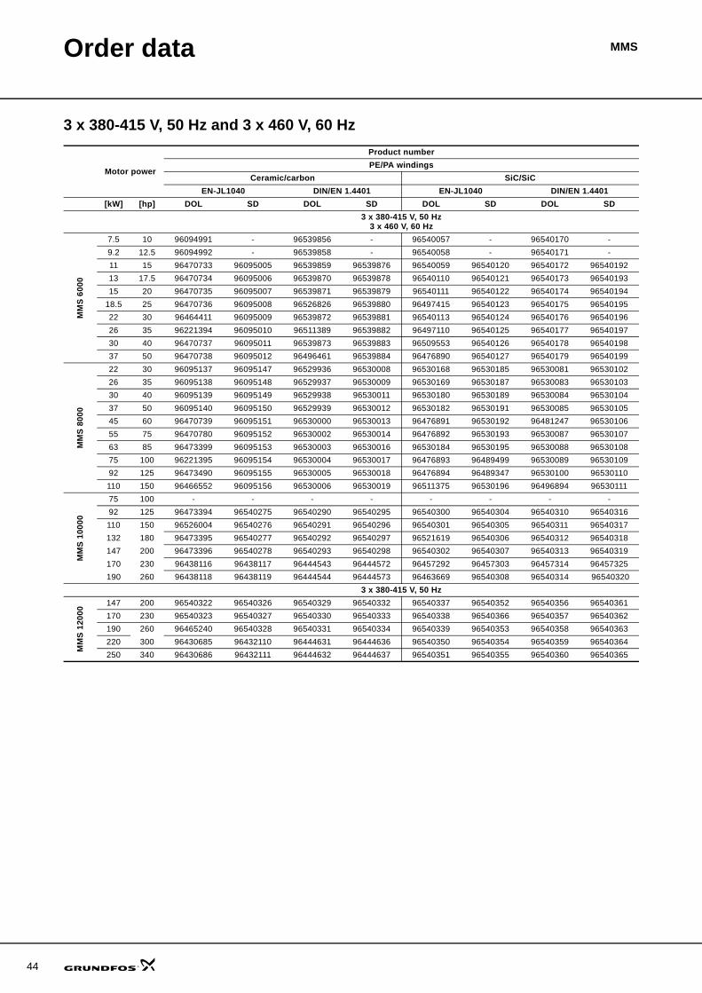
44
Order data MMS
3 x 380-415 V, 50 Hz and 3 x 460 V, 60 Hz
Motor power
Product numberPE/PA windings
Ceramic/carbon SiC/SiCEN-JL1040 DIN/EN 1.4401 EN-JL1040 DIN/EN 1.4401
[kW] [hp] DOL SD DOL SD DOL SD DOL SD3 x 380-415 V, 50 Hz
3 x 460 V, 60 Hz
MM
S 60
00
7.5 10 96094991 - 96539856 - 96540057 - 96540170 -9.2 12.5 96094992 - 96539858 - 96540058 - 96540171 -11 15 96470733 96095005 96539859 96539876 96540059 96540120 96540172 9654019213 17.5 96470734 96095006 96539870 96539878 96540110 96540121 96540173 9654019315 20 96470735 96095007 96539871 96539879 96540111 96540122 96540174 96540194
18.5 25 96470736 96095008 96526826 96539880 96497415 96540123 96540175 9654019522 30 96464411 96095009 96539872 96539881 96540113 96540124 96540176 9654019626 35 96221394 96095010 96511389 96539882 96497110 96540125 96540177 9654019730 40 96470737 96095011 96539873 96539883 96509553 96540126 96540178 9654019837 50 96470738 96095012 96496461 96539884 96476890 96540127 96540179 96540199
MM
S 80
00
22 30 96095137 96095147 96529936 96530008 96530168 96530185 96530081 9653010226 35 96095138 96095148 96529937 96530009 96530169 96530187 96530083 9653010330 40 96095139 96095149 96529938 96530011 96530180 96530189 96530084 9653010437 50 96095140 96095150 96529939 96530012 96530182 96530191 96530085 9653010545 60 96470739 96095151 96530000 96530013 96476891 96530192 96481247 9653010655 75 96470780 96095152 96530002 96530014 96476892 96530193 96530087 9653010763 85 96473399 96095153 96530003 96530016 96530184 96530195 96530088 9653010875 100 96221395 96095154 96530004 96530017 96476893 96489499 96530089 9653010992 125 96473490 96095155 96530005 96530018 96476894 96489347 96530100 96530110110 150 96466552 96095156 96530006 96530019 96511375 96530196 96496894 96530111
MM
S 10
000
75 100 - - - - - - - -92 125 96473394 96540275 96540290 96540295 96540300 96540304 96540310 96540316110 150 96526004 96540276 96540291 96540296 96540301 96540305 96540311 96540317132 180 96473395 96540277 96540292 96540297 96521619 96540306 96540312 96540318147 200 96473396 96540278 96540293 96540298 96540302 96540307 96540313 96540319170 230 96438116 96438117 96444543 96444572 96457292 96457303 96457314 96457325190 260 96438118 96438119 96444544 96444573 96463669 96540308 96540314 96540320
3 x 380-415 V, 50 Hz
MM
S 12
000 147 200 96540322 96540326 96540329 96540332 96540337 96540352 96540356 96540361
170 230 96540323 96540327 96540330 96540333 96540338 96540366 96540357 96540362190 260 96465240 96540328 96540331 96540334 96540339 96540353 96540358 96540363220 300 96430685 96432110 96444631 96444636 96540350 96540354 96540359 96540364250 340 96430686 96432111 96444632 96444637 96540351 96540355 96540360 96540365
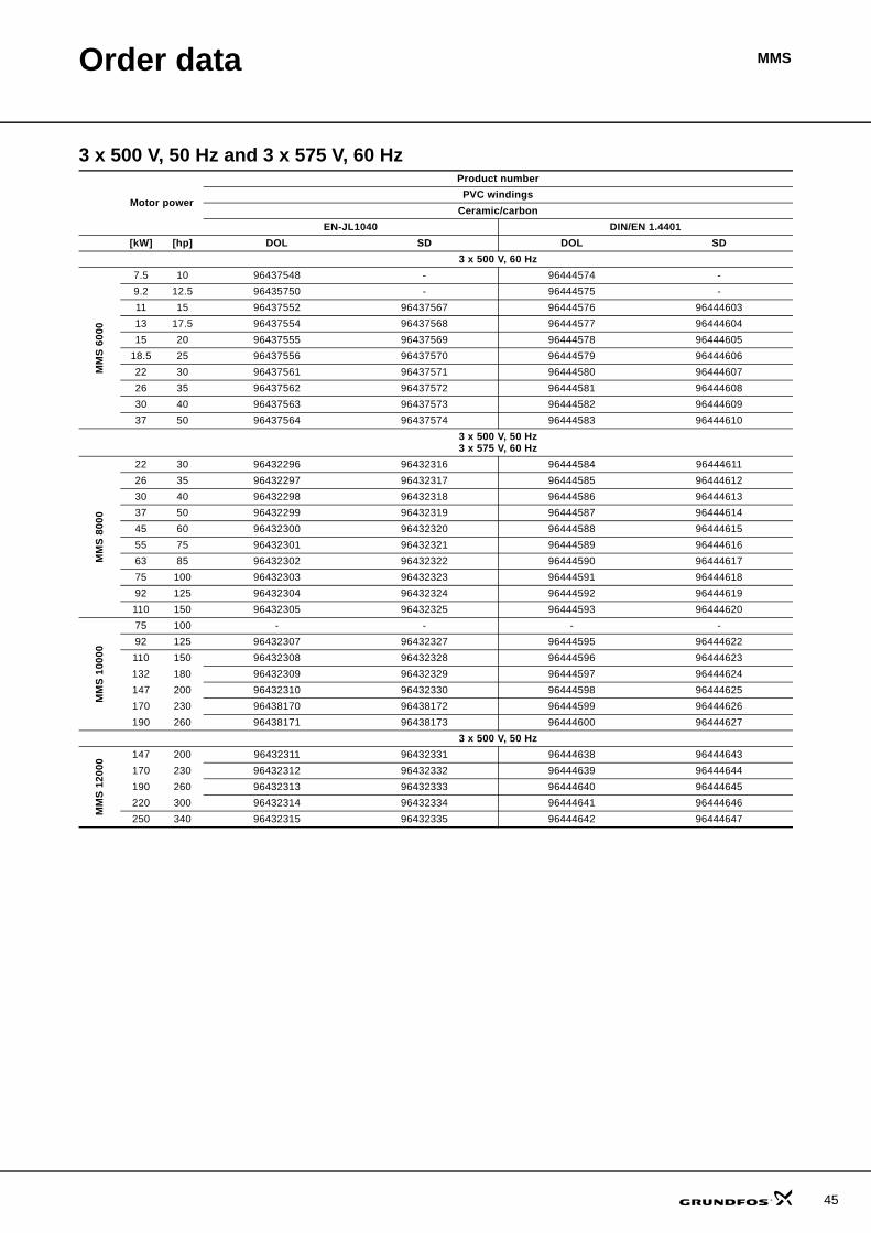
Order data MMS
3 x 500 V, 50 Hz and 3 x 575 V, 60 Hz
Motor power
Product numberPVC windings
Ceramic/carbonEN-JL1040 DIN/EN 1.4401
[kW] [hp] DOL SD DOL SD3 x 500 V, 60 Hz
MM
S 60
00
7.5 10 96437548 - 96444574 -9.2 12.5 96435750 - 96444575 -11 15 96437552 96437567 96444576 9644460313 17.5 96437554 96437568 96444577 9644460415 20 96437555 96437569 96444578 96444605
18.5 25 96437556 96437570 96444579 9644460622 30 96437561 96437571 96444580 9644460726 35 96437562 96437572 96444581 9644460830 40 96437563 96437573 96444582 9644460937 50 96437564 96437574 96444583 96444610
3 x 500 V, 50 Hz3 x 575 V, 60 Hz
MM
S 80
00
22 30 96432296 96432316 96444584 9644461126 35 96432297 96432317 96444585 9644461230 40 96432298 96432318 96444586 9644461337 50 96432299 96432319 96444587 9644461445 60 96432300 96432320 96444588 9644461555 75 96432301 96432321 96444589 9644461663 85 96432302 96432322 96444590 9644461775 100 96432303 96432323 96444591 9644461892 125 96432304 96432324 96444592 96444619110 150 96432305 96432325 96444593 96444620
MM
S 10
000
75 100 - - - -92 125 96432307 96432327 96444595 96444622110 150 96432308 96432328 96444596 96444623132 180 96432309 96432329 96444597 96444624147 200 96432310 96432330 96444598 96444625170 230 96438170 96438172 96444599 96444626190 260 96438171 96438173 96444600 96444627
3 x 500 V, 50 Hz
MM
S 12
000 147 200 96432311 96432331 96444638 96444643
170 230 96432312 96432332 96444639 96444644190 260 96432313 96432333 96444640 96444645220 300 96432314 96432334 96444641 96444646250 340 96432315 96432335 96444642 96444647
45
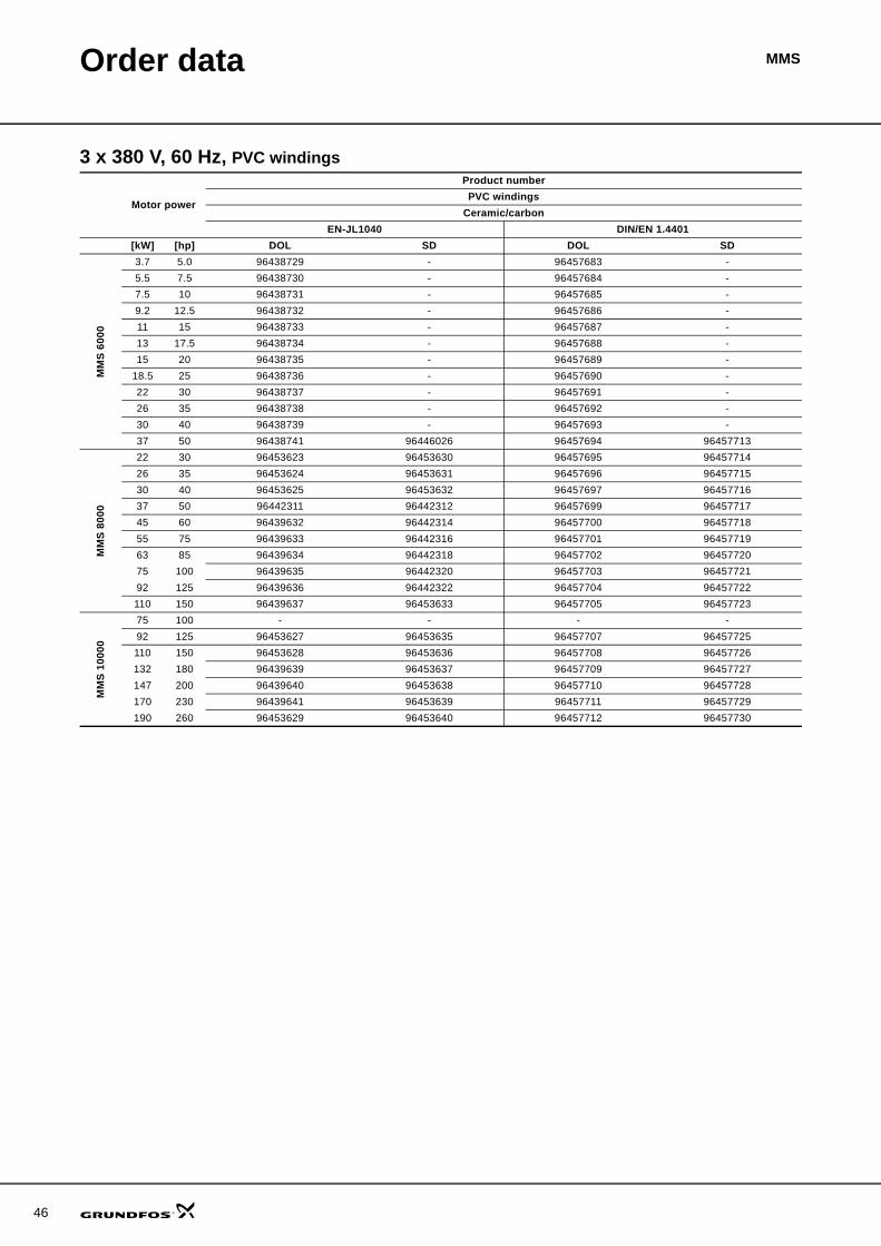
46
Order data MMS
3 x 380 V, 60 Hz, PVC windings
Motor power
Product numberPVC windings
Ceramic/carbonEN-JL1040 DIN/EN 1.4401
[kW] [hp] DOL SD DOL SD
MM
S 60
00
3.7 5.0 96438729 - 96457683 -5.5 7.5 96438730 - 96457684 -7.5 10 96438731 - 96457685 -9.2 12.5 96438732 - 96457686 -11 15 96438733 - 96457687 -13 17.5 96438734 - 96457688 -15 20 96438735 - 96457689 -
18.5 25 96438736 - 96457690 -22 30 96438737 - 96457691 -26 35 96438738 - 96457692 -30 40 96438739 - 96457693 -37 50 96438741 96446026 96457694 96457713
MM
S 80
00
22 30 96453623 96453630 96457695 9645771426 35 96453624 96453631 96457696 9645771530 40 96453625 96453632 96457697 9645771637 50 96442311 96442312 96457699 9645771745 60 96439632 96442314 96457700 9645771855 75 96439633 96442316 96457701 9645771963 85 96439634 96442318 96457702 9645772075 100 96439635 96442320 96457703 9645772192 125 96439636 96442322 96457704 96457722110 150 96439637 96453633 96457705 96457723
MM
S 10
000
75 100 - - - -92 125 96453627 96453635 96457707 96457725110 150 96453628 96453636 96457708 96457726132 180 96439639 96453637 96457709 96457727147 200 96439640 96453638 96457710 96457728170 230 96439641 96453639 96457711 96457729190 260 96453629 96453640 96457712 96457730
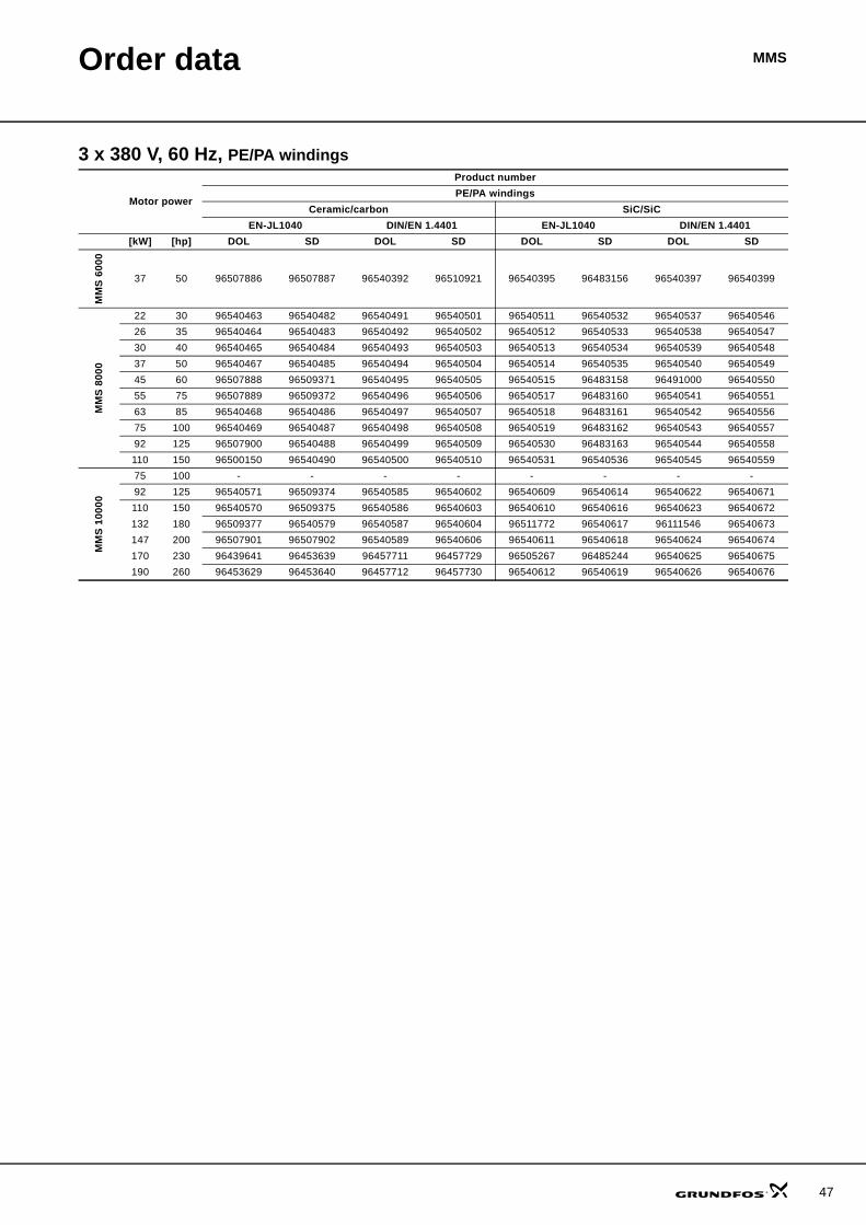
Order data MMS
3 x 380 V, 60 Hz, PE/PA windings
Motor power
Product numberPE/PA windings
Ceramic/carbon SiC/SiCEN-JL1040 DIN/EN 1.4401 EN-JL1040 DIN/EN 1.4401
[kW] [hp] DOL SD DOL SD DOL SD DOL SD
MM
S 60
00
37 50 96507886 96507887 96540392 96510921 96540395 96483156 96540397 96540399
MM
S 80
00
22 30 96540463 96540482 96540491 96540501 96540511 96540532 96540537 9654054626 35 96540464 96540483 96540492 96540502 96540512 96540533 96540538 9654054730 40 96540465 96540484 96540493 96540503 96540513 96540534 96540539 9654054837 50 96540467 96540485 96540494 96540504 96540514 96540535 96540540 9654054945 60 96507888 96509371 96540495 96540505 96540515 96483158 96491000 9654055055 75 96507889 96509372 96540496 96540506 96540517 96483160 96540541 9654055163 85 96540468 96540486 96540497 96540507 96540518 96483161 96540542 9654055675 100 96540469 96540487 96540498 96540508 96540519 96483162 96540543 9654055792 125 96507900 96540488 96540499 96540509 96540530 96483163 96540544 96540558110 150 96500150 96540490 96540500 96540510 96540531 96540536 96540545 96540559
MM
S 10
000
75 100 - - - - - - - -92 125 96540571 96509374 96540585 96540602 96540609 96540614 96540622 96540671110 150 96540570 96509375 96540586 96540603 96540610 96540616 96540623 96540672132 180 96509377 96540579 96540587 96540604 96511772 96540617 96111546 96540673147 200 96507901 96507902 96540589 96540606 96540611 96540618 96540624 96540674170 230 96439641 96453639 96457711 96457729 96505267 96485244 96540625 96540675190 260 96453629 96453640 96457712 96457730 96540612 96540619 96540626 96540676
47
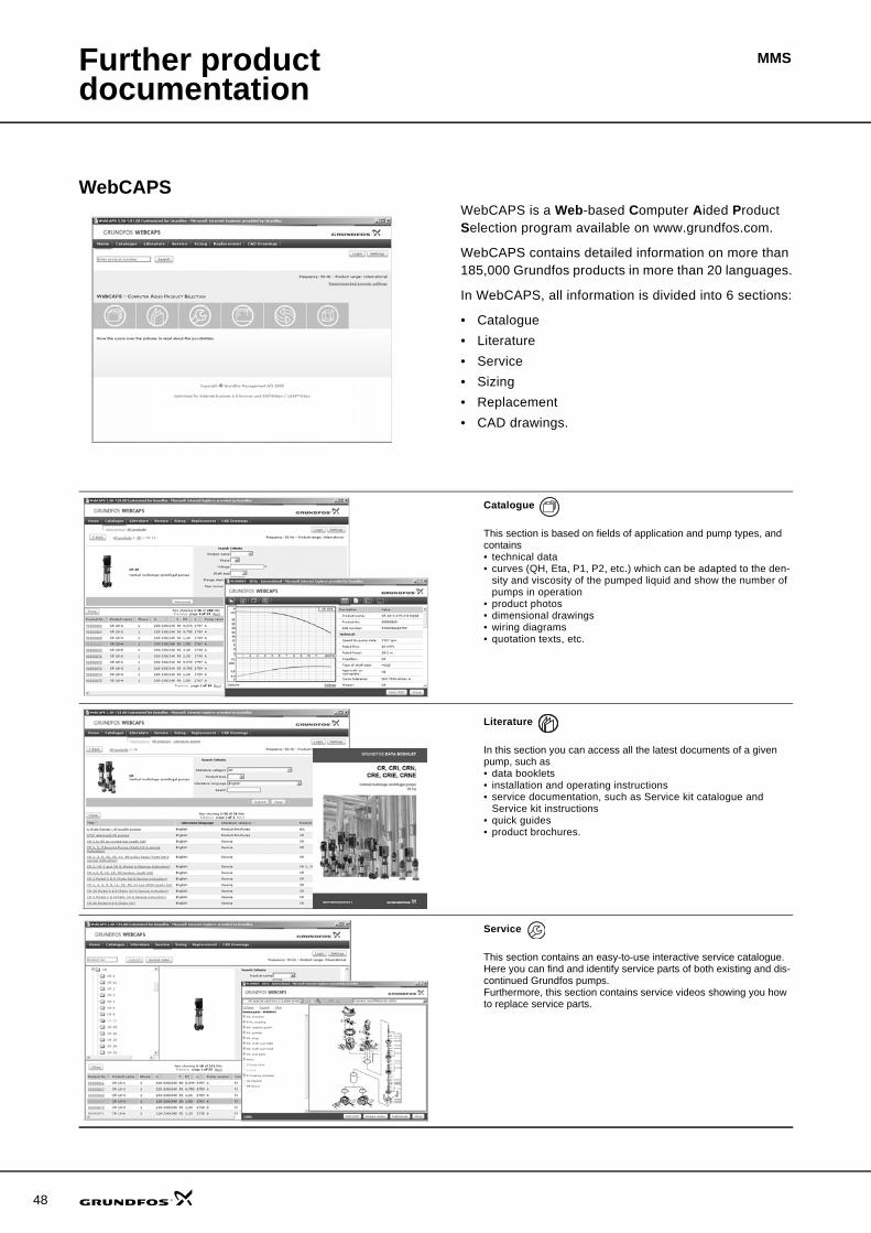
48
MMSFurther product documentation
WebCAPSWebCAPS is a Web-based Computer Aided Product Selection program available on www.grundfos.com.
WebCAPS contains detailed information on more than 185,000 Grundfos products in more than 20 languages.
In WebCAPS, all information is divided into 6 sections:
• Catalogue• Literature• Service• Sizing• Replacement• CAD drawings.
Catalogue
This section is based on fields of application and pump types, and contains • technical data• curves (QH, Eta, P1, P2, etc.) which can be adapted to the den-
sity and viscosity of the pumped liquid and show the number of pumps in operation
• product photos• dimensional drawings• wiring diagrams• quotation texts, etc.
Literature
In this section you can access all the latest documents of a given pump, such as• data booklets• installation and operating instructions• service documentation, such as Service kit catalogue and
Service kit instructions• quick guides• product brochures.
Service
This section contains an easy-to-use interactive service catalogue. Here you can find and identify service parts of both existing and dis-continued Grundfos pumps.Furthermore, this section contains service videos showing you how to replace service parts.
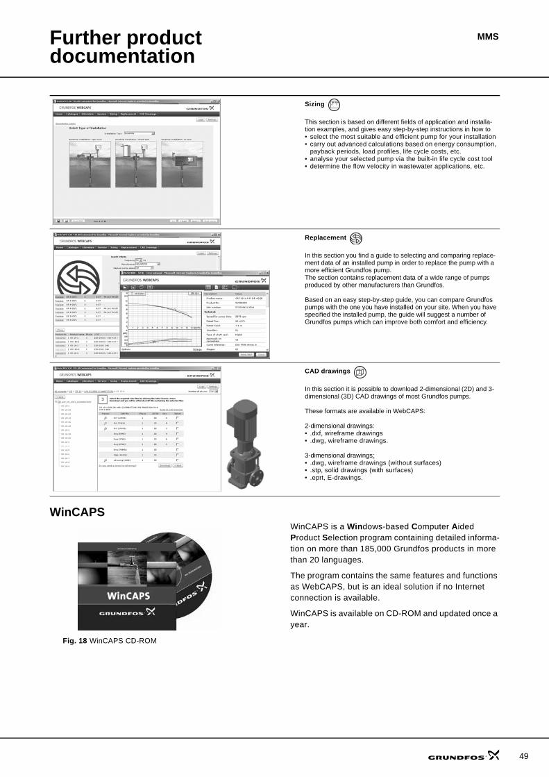
Further product documentation
MMS
WinCAPS
Fig. 18 WinCAPS CD-ROM
WinCAPS is a Windows-based Computer Aided Product Selection program containing detailed informa-tion on more than 185,000 Grundfos products in more than 20 languages.
The program contains the same features and functions as WebCAPS, but is an ideal solution if no Internet connection is available.
WinCAPS is available on CD-ROM and updated once a year.
Sizing
This section is based on different fields of application and installa-tion examples, and gives easy step-by-step instructions in how to• select the most suitable and efficient pump for your installation• carry out advanced calculations based on energy consumption,
payback periods, load profiles, life cycle costs, etc.• analyse your selected pump via the built-in life cycle cost tool• determine the flow velocity in wastewater applications, etc.
Replacement
In this section you find a guide to selecting and comparing replace-ment data of an installed pump in order to replace the pump with a more efficient Grundfos pump. The section contains replacement data of a wide range of pumps produced by other manufacturers than Grundfos.
Based on an easy step-by-step guide, you can compare Grundfos pumps with the one you have installed on your site. When you have specified the installed pump, the guide will suggest a number of Grundfos pumps which can improve both comfort and efficiency.
CAD drawings
In this section it is possible to download 2-dimensional (2D) and 3-dimensional (3D) CAD drawings of most Grundfos pumps.
These formats are available in WebCAPS:
2-dimensional drawings:• .dxf, wireframe drawings• .dwg, wireframe drawings.
3-dimensional drawings:• .dwg, wireframe drawings (without surfaces)• .stp, solid drawings (with surfaces)• .eprt, E-drawings.
0 1
49

www.grundfos.com
V7156900 0108 GBRepl. V71156900 0905 Subject to alterations.
Being responsible is our foundationThinking ahead makes it possible
Innovation is the essence
GRUNDFOS A/S . DK-8850 Bjerringbro . DenmarkTelephone: +45 87 50 14 00


![Grundfos NB 32-125.1/140 pump : NB32-125.1/140 A-F2-A-BAQE ... · 2000 2200 2400 2600 2800 P1 [kW] 0.0 1.0 2.0 3.0 4.0 n P1 7/12. Printed from Grundfos Product Centre [2018.06.003]](https://static.fdocuments.us/doc/165x107/5f5e4734a5a0452ae87df30a/grundfos-nb-32-1251140-pump-nb32-1251140-a-f2-a-baqe-2000-2200-2400-2600.jpg)