GRUNDFOS DATA BOOKLET - · PDF filePerformance data DMX 221 17 ... The Grundfos DMX is a...
32
GRUNDFOS DATA BOOKLET DMX Dosing pumps MECHANICAL DOSING
Transcript of GRUNDFOS DATA BOOKLET - · PDF filePerformance data DMX 221 17 ... The Grundfos DMX is a...
GRUNDFOS DATA BOOKLET
DMXDosing pumps
MECHANICAL DOSING
Ta
ble
of c
on
ten
ts
2
DMX
1. Features and benefits 3Reliable diaphragm dosing 3Servomotor 4AR microprocessor electronics Etron Profi 4
2. Performance range 5DMX 221, 226 (50 Hz) 5DMX 227 (50 Hz) 5DMX 227 (100 Hz) 5
3. Identification 6Type key DMX 221 6Type key DMX 226 7Type key DMX 227 8
4. Functions 9Overview of possible capacity control functions 9Capacity control by stroke-length adjustment 9Capacity control by motor frequency converter 10Capacity control by AR electronics (Etron Profi) 10
5. Construction 11General description 11DMX 221 11DMX 226 12DMX 227 13
6. Technical data 14Dimensions DMX 221 14Dimensions DMX 226 15Dimensions DMX 227 16Performance data DMX 221 17Performance data DMX 226 18Performance data DMX 227 19Suction lift DMX 221 20Suction lift DMX 226 21Suction lift DMX 227 22Weights DMX 221 22Weights DMX 226 22Weights DMX 227 23Sound pressure 23Accuracy 23Permissible temperature of dosing liquid 23
7. Selection of pump 24DMX 221 standard range (4 to 115 l/h) 24DMX 226 M standard range (24 to 380 l/h) 24DMX 226 L standard range (67 to 765 l/h) 25DMX 227 standard range (430 to 2000 l/h) 25DMX non-standard range (4 to 2 x 765 l/h) 26
8. Accessories 28Overview of a dosing system 28
9. Pumped liquids 29List of pumped liquids 29
10. Further product documentation 30WebCAPS 30WinCAPS 31
Fe
atu
res
an
d b
en
efi
ts
DMX 1
1. Features and benefits
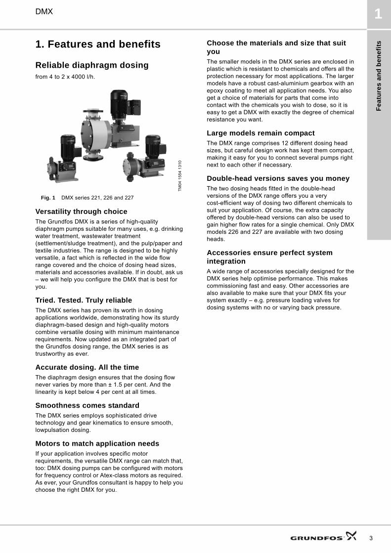
Reliable diaphragm dosingfrom 4 to 2 x 4000 l/h.
Fig. 1 DMX series 221, 226 and 227
Versatility through choiceThe Grundfos DMX is a series of high-quality diaphragm pumps suitable for many uses, e.g. drinking water treatment, wastewater treatment (settlement/sludge treatment), and the pulp/paper and textile industries. The range is designed to be highly versatile, a fact which is reflected in the wide flow range covered and the choice of dosing head sizes, materials and accessories available. If in doubt, ask us – we will help you configure the DMX that is best for you.
Tried. Tested. Truly reliableThe DMX series has proven its worth in dosing applications worldwide, demonstrating how its sturdy diaphragm-based design and high-quality motors combine versatile dosing with minimum maintenance requirements. Now updated as an integrated part of the Grundfos dosing range, the DMX series is as trustworthy as ever.
Accurate dosing. All the timeThe diaphragm design ensures that the dosing flow never varies by more than ± 1.5 per cent. And the linearity is kept below 4 per cent at all times.
Smoothness comes standardThe DMX series employs sophisticated drive technology and gear kinematics to ensure smooth, lowpulsation dosing.
Motors to match application needsIf your application involves specific motor requirements, the versatile DMX range can match that, too: DMX dosing pumps can be configured with motors for frequency control or Atex-class motors as required. As ever, your Grundfos consultant is happy to help you choose the right DMX for you.
Choose the materials and size that suit youThe smaller models in the DMX series are enclosed in plastic which is resistant to chemicals and offers all the protection necessary for most applications. The larger models have a robust cast-aluminium gearbox with an epoxy coating to meet all application needs. You also get a choice of materials for parts that come into contact with the chemicals you wish to dose, so it is easy to get a DMX with exactly the degree of chemical resistance you want.
Large models remain compactThe DMX range comprises 12 different dosing head sizes, but careful design work has kept them compact, making it easy for you to connect several pumps right next to each other if necessary.
Double-head versions saves you moneyThe two dosing heads fitted in the double-head versions of the DMX range offers you a very cost-efficient way of dosing two different chemicals to suit your application. Of course, the extra capacity offered by double-head versions can also be used to gain higher flow rates for a single chemical. Only DMX models 226 and 227 are available with two dosing heads.
Accessories ensure perfect system integrationA wide range of accessories specially designed for the DMX series help optimise performance. This makes commissioning fast and easy. Other accessories are also available to make sure that your DMX fits your system exactly – e.g. pressure loading valves for dosing systems with no or varying back pressure.
TM
04
15
54
13
10
3

Fe
atu
res
an
d b
en
efits
4
DMX1
ServomotorTo facilitate automatic control of the flow rate, the DMX 221 and DMX 226 pumps can be equipped with an electric servomotor in a metal housing IP65. The servomotor primarily consists of an overload-proof synchronous motor, reduction gear, feedback potentiometer 1000 Ω and min/max limit switches.The servomotor is connected to the stroke-adjusting spindle of the dosing pump and adjusts the stroke length from 0 to 100 % with a rotation angle of 27 °.Apart from the standard version the following variants are also available:• Servomotors with different operating voltages• With integrated electronics for 4-20 mA analog
signals input/output with manual/automatic switches
Fig. 2 DMX 221 with servomotor
AR microprocessor electronics Etron ProfiConvenient electronics in a plastic housing IP65 for DMX 221 and DMX 226 pumps with AC motor.
Variants• Etron Profi for mounting on the terminal box,
115/230 V, 50/60 Hz• Etron Profi for wall mounting, 115/230 V, 50/60 Hz,
5 m of cable to the pump
Control modes• Manual: stroke frequency manually adjustable from
1 up to the maximum strokes per minute
• Pulse signal control: multiplier 1:n (n strokes per coming pulse) and divisor n:1 (1 stroke per coming n pulses), memory function (stores a maximum of 65,000 pulses)
• Analog signal control 0/4-20 mA: adjustment of stroke frequency proportional to the analog signal, weighting of current input is possible
Inputs• Pulse signal
• Analog signal
• Remote on/off
• Tank-empty sensor
• Dosing controller and diaphragm leakage sensor
Outputs• Analog signal
• Error signal (fault)
• Stroke signal
• Pre-alert signal
Fig. 3 DMX 226 M with AR electronics Etron Profi
TM
04
15
55
13
10
TM
04
15
56
13
10
Pe
rfo
rma
nc
e r
an
ge
DMX 2
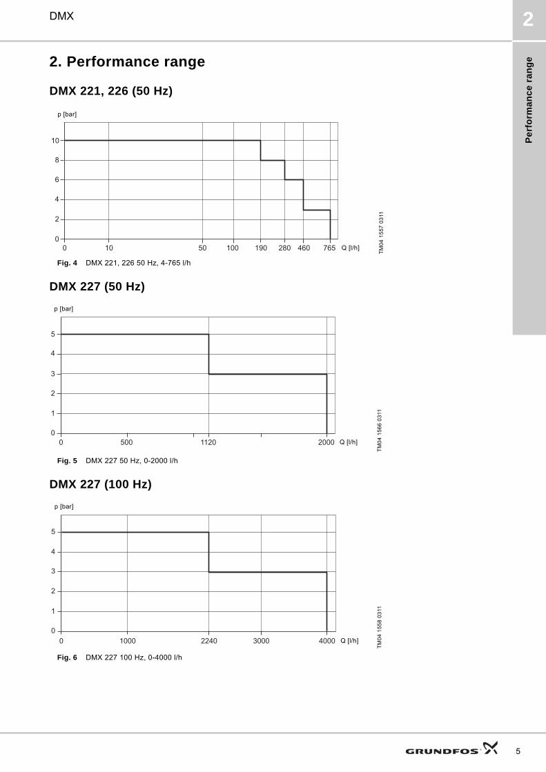
2. Performance range
DMX 221, 226 (50 Hz)
Fig. 4 DMX 221, 226 50 Hz, 4-765 l/h
DMX 227 (50 Hz)
Fig. 5 DMX 227 50 Hz, 0-2000 l/h
DMX 227 (100 Hz)
Fig. 6 DMX 227 100 Hz, 0-4000 l/h
TM
04
15
57
03
11T
M0
4 1
56
6 0
311
TM
04
15
58
03
11
1000
2
4
6
8
10
50 100 190 280 460 765
p [bar]
Q [l/h]
00
1
2
3
4
5
500 1120 2000 Q [l/h]
p [bar]
00
1
2
3
4
5
1000 2240 3000 4000 Q [l/h]
p [bar]
5
Ide
ntific
atio
n
6
DMX3
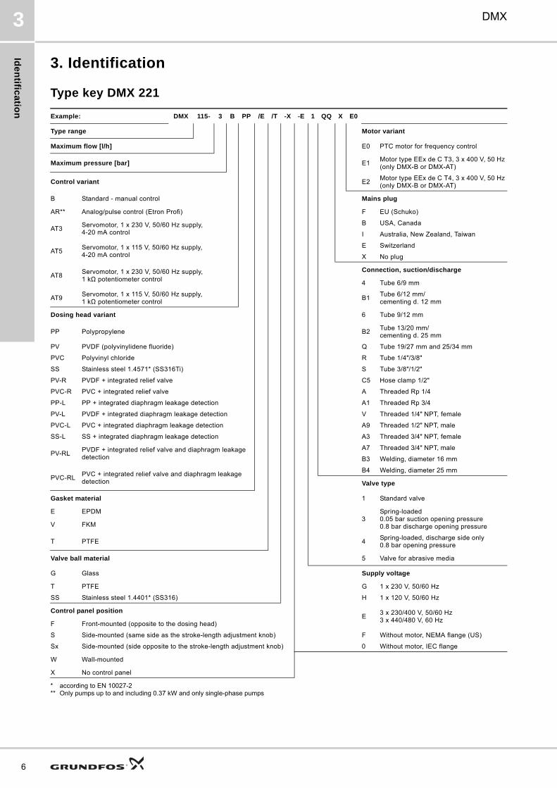
3. Identification
Type key DMX 221
* according to EN 10027-2** Only pumps up to and including 0.37 kW and only single-phase pumps
Example: DMX 115- 3 B PP /E /T -X -E 1 QQ X E0
Type range Motor variant
Maximum flow [l/h] E0 PTC motor for frequency control
Maximum pressure [bar] E1Motor type EEx de C T3, 3 x 400 V, 50 Hz (only DMX-B or DMX-AT)
Control variant E2Motor type EEx de C T4, 3 x 400 V, 50 Hz (only DMX-B or DMX-AT)
B Standard - manual control Mains plug
AR** Analog/pulse control (Etron Profi) F EU (Schuko)
AT3Servomotor, 1 x 230 V, 50/60 Hz supply, 4-20 mA control
B USA, Canada
I Australia, New Zealand, Taiwan
AT5Servomotor, 1 x 115 V, 50/60 Hz supply, 4-20 mA control
E Switzerland
X No plug
AT8Servomotor, 1 x 230 V, 50/60 Hz supply, 1 kΩ potentiometer control
Connection, suction/discharge
4 Tube 6/9 mm
AT9Servomotor, 1 x 115 V, 50/60 Hz supply, 1 kΩ potentiometer control
B1Tube 6/12 mm/cementing d. 12 mm
Dosing head variant 6 Tube 9/12 mm
PP Polypropylene B2Tube 13/20 mm/cementing d. 25 mm
PV PVDF (polyvinylidene fluoride) Q Tube 19/27 mm and 25/34 mm
PVC Polyvinyl chloride R Tube 1/4"/3/8"
SS Stainless steel 1.4571* (SS316Ti) S Tube 3/8"/1/2"
PV-R PVDF + integrated relief valve C5 Hose clamp 1/2"
PVC-R PVC + integrated relief valve A Threaded Rp 1/4
PP-L PP + integrated diaphragm leakage detection A1 Threaded Rp 3/4
PV-L PVDF + integrated diaphragm leakage detection V Threaded 1/4" NPT, female
PVC-L PVC + integrated diaphragm leakage detection A9 Threaded 1/2" NPT, male
SS-L SS + integrated diaphragm leakage detection A3 Threaded 3/4" NPT, female
PV-RLPVDF + integrated relief valve and diaphragm leakage detection
A7 Threaded 3/4" NPT, male
B3 Welding, diameter 16 mm
PVC-RLPVC + integrated relief valve and diaphragm leakage detection
B4 Welding, diameter 25 mm
Valve type
Gasket material 1 Standard valve
E EPDM3
Spring-loaded0.05 bar suction opening pressure0.8 bar discharge opening pressureV FKM
T PTFE 4Spring-loaded, discharge side only0.8 bar opening pressure
Valve ball material 5 Valve for abrasive media
G Glass Supply voltage
T PTFE G 1 x 230 V, 50/60 Hz
SS Stainless steel 1.4401* (SS316) H 1 x 120 V, 50/60 Hz
Control panel positionE
3 x 230/400 V, 50/60 Hz3 x 440/480 V, 60 Hz
F Front-mounted (opposite to the dosing head)
S Side-mounted (same side as the stroke-length adjustment knob) F Without motor, NEMA flange (US)
Sx Side-mounted (side opposite to the stroke-length adjustment knob) 0 Without motor, IEC flange
W Wall-mounted
X No control panel

Ide
nti
fic
ati
on
DMX 3
Type key DMX 226
* according to EN 10027-2** Only pumps up to and including 525 l/h and only pumps with single-phase motors
Example: DMX 765- 3 B PP /E /T -X -E 1 QQ X E0
Type range Motor variant
DMX E0 PTC motor for frequency control
Maximum flow [l/h] E1Motor type EEx de C T3, 3 x 400 V, 50 Hz (only DMX-B or DMX-AT)
Maximum pressure [bar]E2
Motor type EEx de C T4, 3 x 400 V, 50 Hz (only DMX-B or DMX-AT)
Control variant Mains plug (only 1AC motor)
B Standard X No plug
AR** Analog/pulse control (Etron Profi) F EU (Schuko)
AT3Servomotor, 1 x 230 V, 50/60 Hz supply, 4-20 mA control
B USA, Canada
I Australia, New Zealand, Taiwan
AT5Servomotor, 1 x 115 V, 50/60 Hz supply, 4-20 mA control
E Switzerland
AT8Servomotor, 1 x 230 V, 50/60 Hz supply, 1 kΩ potentiometer control
Connection, suction/discharge
AT9Servomotor, 1 x 115 V, 50/60 Hz supply, 1 kΩ potentiometer control
B9 Tube 19/27 mm, PVC
Q Tube 19/27 mm and 25/34 mm
Dosing head variantA1 Threaded Rp 3/4
A2 Threaded Rp 1 1/4
PP Polypropylene A3 Threaded 3/4" NPT
PV PVDF (polyvinylidene fluoride) A7 Threaded 3/4" NPT, male
PVC Polyvinyl chloride A4 Threaded 1 1/4" NPT
SS Stainless steel 1.4571* (SS316Ti) A8 Threaded 1 1/4" NPT, male
PV-R PVDF + integrated relief valve K Cementing d. 40 mm
PVC-R PVC + integrated relief valveB2
Tube 13/20 mm/cementing d. 25 mmPP-L PP + integrated diaphragm leakage detection
PV-L PVDF + integrated diaphragm leakage detection B4 Welding d. 25 mm
PVC-L PVC + integrated diaphragm leakage detection B5 Welding d. 40 mm
SS-L SS + integrated diaphragm leakage detectionValve type
PV-RLPVDF + integrated relief valve and diaphragm leakage detection 1 Standard
PVC-RLPVC + integrated relief valve and diaphragm leakage detection
4 Spring-loaded, discharge side only
Gasket material5 Valves for abrasive media
Supply voltageE EPDM
V FKM 0 Without motor, IEC flange
T PTFE G 1 x 230 V, 50 Hz
Valve ball materialH 1 x 115 V, 60 Hz
E230/400 V, 50/60 Hz or 440/480 V, 60 HzG Glass
T PTFE F Without motor, NEMA flange (US)
SS Stainless steel 1.4401* (SS316)
Control panel position
X No control panel
F Front-mounted
W Wall-mounted
7

Ide
ntific
atio
n
8
DMX3
Type key DMX 227
* according to EN 10027-2
Example: DMX 2000- 3 D PP /E /PP -X -E 2 TT X E0
Type range Motor variant
DMX E0PTC motor for frequency control, 3 x 400 V
Maximum flow [l/h]E6
PTC motor with frequency control, 3 x 400 V
Mains plug
Maximum pressure [bar]X No plug
Control variant Connection, suction/discharge
D No control unitR
Flange, DN 65, with connector for PVC pipe, 65/75 mm
Dosing head variant
TFlange, DN 65, with connector for PP pipe, 65/75 mmPP Polypropylene
PVC Polyvinyl chloride UFlange, DN 65, with connector for SS pipe, 65/75 mm
SS Stainless steel 1.4571* (SS316Ti) Y Flange, DN 65
PP-L PP + integrated diaphragm leakage detection Z Flange, ANSI, 2 1/2"
PVC-L PVC + integrated diaphragm leakage detectionValve type
SS-L SS + integrated diaphragm leakage detection
Gasket material 2Spring-loaded0.1 bar suction opening pressure0.1 bar discharge opening pressure
E EPDMSupply voltage
V FKM
Valve ball material 0Without motor, flange for single-head pump: IEC BG90 B14double-head pump: IEC BG100 B14
PP PolypropyleneF
Without motor, NEMA flange 145C (US)PVC Polyvinyl chloride
SS Stainless steel 1.4571* (SS316Ti) E 230/400 V, 50 Hz, 460 V, 60 Hz
Control panel position
X No control panel
Fu
nc
tio
ns
DMX 4
4. Functions
Overview of possible capacity control functions
1) AR version only up to capacity (Q) of 525 l/h
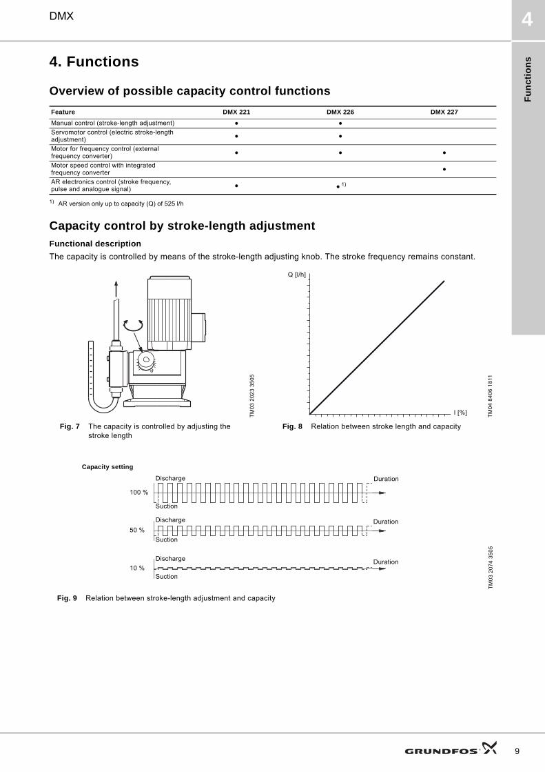
Capacity control by stroke-length adjustment
Functional description
The capacity is controlled by means of the stroke-length adjusting knob. The stroke frequency remains constant.
Fig. 9 Relation between stroke-length adjustment and capacity
Feature DMX 221 DMX 226 DMX 227
Manual control (stroke-length adjustment)
Servomotor control (electric stroke-length adjustment)
Motor for frequency control (external frequency converter)
Motor speed control with integrated frequency converter
AR electronics control (stroke frequency, pulse and analogue signal)
1)
TM
03
20
23
35
05
TM
04
84
06
18
11
Fig. 7 The capacity is controlled by adjusting the stroke length
Fig. 8 Relation between stroke length and capacity
Q [l/h]
l [%]
TM
03
20
74
35
05
Discharge
Suction
Duration
Discharge
Suction
Duration
Discharge
Suction
Duration
Capacity setting
100 %
50 %
10 %
9
Fu
nc
tion
s
10
DMX4
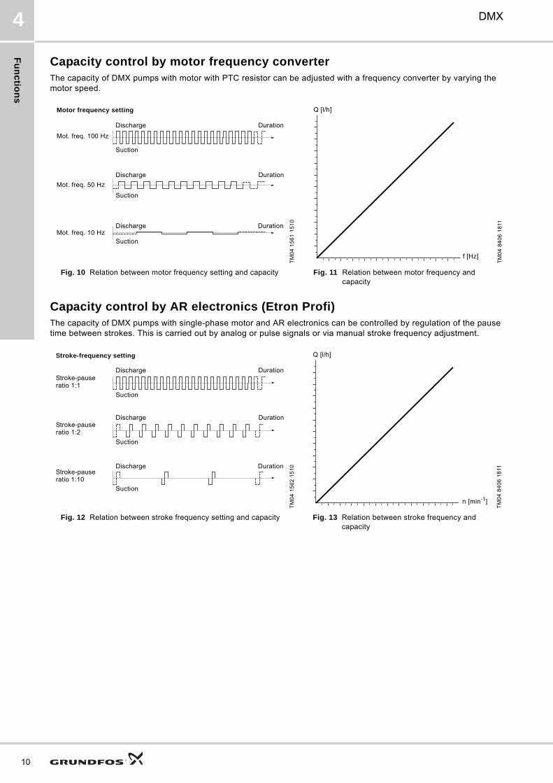
Capacity control by motor frequency converterThe capacity of DMX pumps with motor with PTC resistor can be adjusted with a frequency converter by varying the motor speed.
Capacity control by AR electronics (Etron Profi)The capacity of DMX pumps with single-phase motor and AR electronics can be controlled by regulation of the pause time between strokes. This is carried out by analog or pulse signals or via manual stroke frequency adjustment.
TM
04
15
61
15
10
TM
04
84
06
18
11
Fig. 10 Relation between motor frequency setting and capacity Fig. 11 Relation between motor frequency and capacity
Discharge
Suction
Duration
Discharge
Suction
Duration
Discharge
Suction
Duration
Motor frequency setting
Mot. freq. 100 Hz
Mot. freq. 50 Hz
Mot. freq. 10 Hz
Q [l/h]
f [Hz]
TM
04
15
62
15
10
TM
04
84
06
18
11
Fig. 12 Relation between stroke frequency setting and capacity Fig. 13 Relation between stroke frequency and capacity
Discharge
Suction
Duration
Discharge
Suction
Duration
Discharge
Suction
Duration
Stroke-frequency setting
Stroke-pause ratio 1:1
Stroke-pause ratio 1:2
Stroke-pause ratio 1:10
Q [l/h]
n [min-1]
Co
ns
tru
cti
on
DMX 5
5. Construction
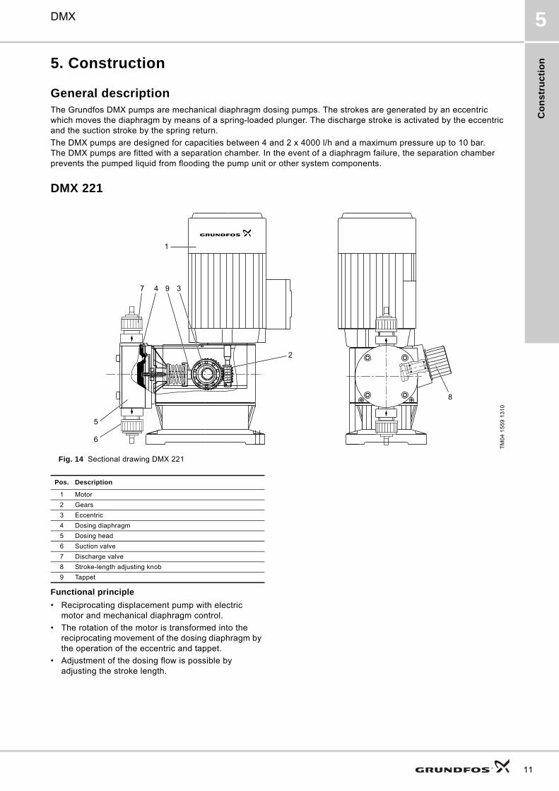
General descriptionThe Grundfos DMX pumps are mechanical diaphragm dosing pumps. The strokes are generated by an eccentric which moves the diaphragm by means of a spring-loaded plunger. The discharge stroke is activated by the eccentric and the suction stroke by the spring return.
The DMX pumps are designed for capacities between 4 and 2 x 4000 l/h and a maximum pressure up to 10 bar. The DMX pumps are fitted with a separation chamber. In the event of a diaphragm failure, the separation chamber prevents the pumped liquid from flooding the pump unit or other system components.
DMX 221
Fig. 14 Sectional drawing DMX 221
Functional principle
• Reciprocating displacement pump with electric motor and mechanical diaphragm control.
• The rotation of the motor is transformed into the reciprocating movement of the dosing diaphragm by the operation of the eccentric and tappet.
• Adjustment of the dosing flow is possible by adjusting the stroke length.
TM
04
15
59
13
10
8
3947
5
6
2
1
Pos. Description
1 Motor
2 Gears
3 Eccentric
4 Dosing diaphragm
5 Dosing head
6 Suction valve
7 Discharge valve
8 Stroke-length adjusting knob
9 Tappet
11
Co
ns
truc
tion
12
DMX5
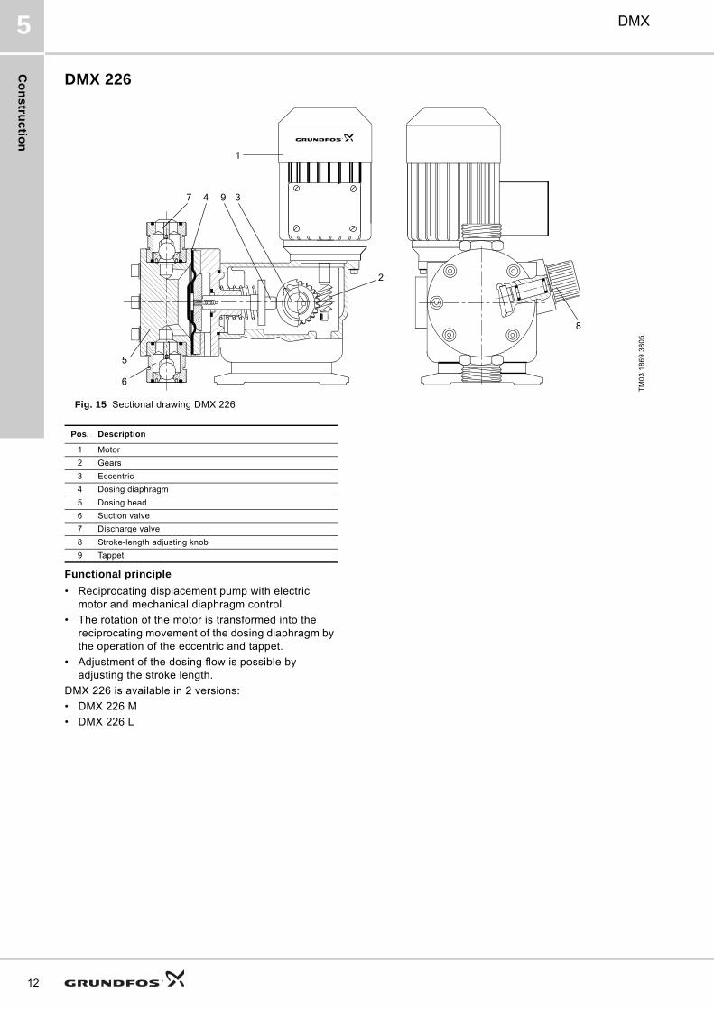
DMX 226
Fig. 15 Sectional drawing DMX 226
Functional principle
• Reciprocating displacement pump with electric motor and mechanical diaphragm control.
• The rotation of the motor is transformed into the reciprocating movement of the dosing diaphragm by the operation of the eccentric and tappet.
• Adjustment of the dosing flow is possible by adjusting the stroke length.
DMX 226 is available in 2 versions:
• DMX 226 M
• DMX 226 L
TM
03
18
69
38
05
8
3947
5
6
2
1
Pos. Description
1 Motor
2 Gears
3 Eccentric
4 Dosing diaphragm
5 Dosing head
6 Suction valve
7 Discharge valve
8 Stroke-length adjusting knob
9 Tappet
Co
ns
tru
cti
on
DMX 5
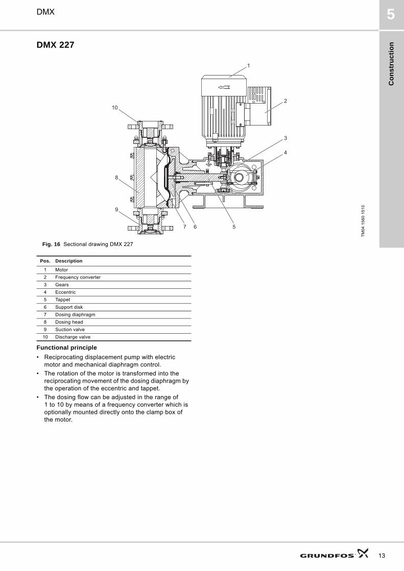
DMX 227
Fig. 16 Sectional drawing DMX 227
Functional principle
• Reciprocating displacement pump with electric motor and mechanical diaphragm control.
• The rotation of the motor is transformed into the reciprocating movement of the dosing diaphragm by the operation of the eccentric and tappet.
• The dosing flow can be adjusted in the range of 1 to 10 by means of a frequency converter which is optionally mounted directly onto the clamp box of the motor.
TM
04
15
60
15
10
4
3
2
1
567
9
10
8
Pos. Description
1 Motor
2 Frequency converter
3 Gears
4 Eccentric
5 Tappet
6 Support disk
7 Dosing diaphragm
8 Dosing head
9 Suction valve
10 Discharge valve
13

Te
ch
nic
al d
ata
14
DMX6
6. Technical data
Dimensions DMX 221
Fig. 17 Dimensions DMX 221
TM
03
17
31
36
05
PumpA B C C1 D D1 D2 E F G I K M N Q
[mm] [mm] [mm] [mm] [mm] [mm] [mm] [mm] [mm] [mm] [mm] [mm] [mm] [mm] [mm]
DMX 4-10 275 319 105 10.5 175 R 5/8 6.5 153 159 102.5 25 32 180 123 179
DMX 7-10 275 319 105 10.5 175 R 5/8 6.5 153 159 102.5 25 32 180 123 179
DMX 8-10 275 319 105 10.5 175 R 5/8 6.5 153 159 102.5 25 32 180 123 179
DMX 9-10 275 319 105 10.5 175 R 5/8 6.5 153 159 102.5 25 32 180 123 179
DMX 12-10 275 319 105 10.5 175 R 5/8 6.5 153 159 102.5 25 32 180 123 179
DMX 14-10 275 319 105 10.5 175 R 5/8 6.5 153 159 102.5 25 32 180 123 179
DMX 16-10 275 319 105 10.5 175 R 5/8 6.5 153 159 102.5 25 32 180 123 179
DMX 17-4 323 319 105 10.5 175 R 1 1/4 6.5 177 159 102.5 38 64 180 123 192
DMX 18-10 275 319 105 10.5 175 R 5/8 6.5 153 159 102.5 25 32 180 123 179
DMX 25-3 330 319 105 10.5 175 R 1 1/4 6.5 188 159 102.5 40 80 180 123 197
DMX 26-10 275 319 105 10.5 175 R 5/8 6.5 153 159 102.5 25 32 180 123 179
DMX 27-10 275 319 105 10.5 175 R 5/8 6.5 153 159 102.5 25 32 180 123 179
DMX 35-10 275 319 105 10.5 175 R 5/8 6.5 153 159 102.5 25 32 180 123 179
DMX 39-4 323 319 105 10.5 175 R 1 1/4 6.5 177 159 102.5 38 64 180 123 192
DMX 50-10 275 319 105 10.5 175 R 5/8 6.5 153 159 102.5 25 32 180 123 179
DMX 60-3 330 319 105 10.5 175 R 1 1/4 6.5 188 159 102.5 40 80 180 123 197
DMX 75-4 323 319 105 10.5 175 R 1 1/4 6.5 177 159 102.5 38 64 180 123 192
DMX 115-3 330 319 105 10.5 175 R 1 1/4 6.5 188 159 102.5 40 80 180 123 197

Te
ch
nic
al
da
ta
DMX 6
Dimensions DMX 226
TM
03
20
86
36
05
Fig. 18 Dimensions DMX 226, version M Fig. 19 Dimensions DMX 226, version L
Pump VersionA B C D D1 D2 E F Fx G H K M Mx N R
[mm] [mm] [mm] [mm] [mm] [mm] [mm] [mm] [mm] [mm] [mm] [mm] [mm] [mm] [mm]
DMX 24-8 M 302 310 97.5 190 G 1 1/4 9 178 152 - 85.5 425 104.5 180 180 118 4
DMX 37-5 M 302 310 97.5 190 G 1 1/4 9 178 152 - 85.5 425 104.5 180 180 118 4
DMX 52-8 M 302 310 97.5 190 G 1 1/4 9 178 152 - 85.5 425 104.5 180 180 118 4
DMX 60-3 M 302 310 97.5 190 G 1 1/4 9 178 152 - 85.5 425 104.5 180 180 118 4
DMX 67-10 L 366 372 136 222 G 1 1/4 9 178 140 208 123 440 80 190 258 160 34
DMX 82-5 M 302 310 97.5 190 G 1 1/4 9 178 152 - 85.5 425 104.5 180 180 118 4
DMX 95-8 L 366 372 136 222 G 1 1/4 9 188 140 208 123 444 80 190 258 160 29
DMX 100-8 M 302 310 97.5 190 G 1 1/4 9 178 152 - 85.5 425 104.5 180 180 118 4
DMX 130-3 M 302 310 97.5 190 G 1 1/4 9 178 152 - 85.5 425 104.5 180 180 118 4
DMX 132-10 L 366 372 136 222 G 1 1/4 9 178 140 208 123 440 80 190 258 160 34
DMX 142-8 M 302 310 97.5 190 G 1 1/4 9 178 152 - 85.5 425 104.5 180 180 118 4
DMX 152-6 L - 372 136 222 G 1 1/4 9 208 140 208 123 453 83 190 258 160 19
DMX 160-5 M 302 310 97.5 190 G 1 1/4 9 178 152 - 85.5 425 104.5 180 180 118 4
DMX 190-8/10 L 366 372 136 222 G 1 1/4 9 178 140 208 123 440 80 190 258 160 34
DMX 199-8 L 366 372 136 222 G 1 1/4 9 188 140 208 123 444 80 190 258 160 29
DMX 230-5 M 302 310 97.5 190 G 1 1/4 9 178 152 - 85.5 425 104.5 180 180 118 4
DMX 249-3 L - 390 136 222 G 2 9 240 140 208 123 498 92 190 258 160 3
DMX 255-3 M 302 310 97.5 190 G 1 1/4 9 178 152 - 85.5 425 104.5 180 180 118 4
DMX 280-6/8 L 366 372 136 222 G 1 1/4 9 188 140 208 123 444 80 190 258 160 29
DMX 315-3 L - 390 136 222 G 2 9 240 140 208 123 498 92 190 258 160 3
DMX 321-4/6 L - 372 136 222 G 1 1/4 9 208 140 208 123 453 83 190 258 160 19
DMX 380-3 M 302 310 97.5 190 G 1 1/4 9 178 152 - 85.5 425 104.5 180 180 118 4
DMX 460-3.5/6 L - 372 136 222 G 1 1/4 9 208 140 208 123 453 83 190 258 160 19
DMX 525-3 L - 390 136 222 G 2 9 240 140 208 123 498 92 190 258 160 3
DMX 765-3 L - 390 136 222 G 2 9 240 140 208 123 498 92 190 258 160 3
15
Te
ch
nic
al d
ata
16
DMX6
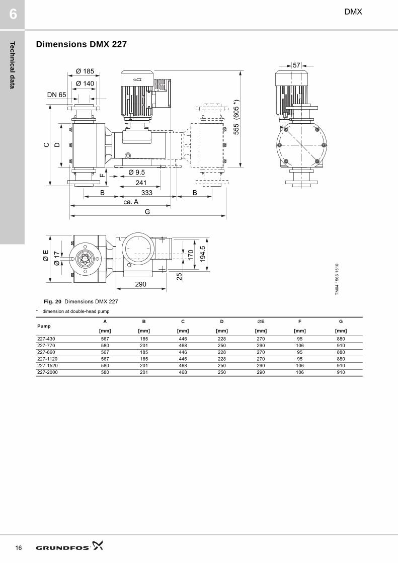
Dimensions DMX 227
* dimension at double-head pump
TM
04
15
65
15
10
Fig. 20 Dimensions DMX 227
170
290
25
Ø 1
7
194.
5
Ø E
G
FDN 65
C
241Ø 9.5
Ø 185
Ø 140
D
ca. A B 333 B
555
(605
*)
57
PumpA B C D ∅E F G
[mm] [mm] [mm] [mm] [mm] [mm] [mm]
227-430 567 185 446 228 270 95 880
227-770 580 201 468 250 290 106 910
227-860 567 185 446 228 270 95 880
227-1120 567 185 446 228 270 95 880
227-1520 580 201 468 250 290 106 910
227-2000 580 201 468 250 290 106 910

Te
ch
nic
al
da
ta
DMX 6
Performance data DMX 221
1) The maximum flow is measured at maximum counterpressure2) Maximum counterpressure3) PTC available for frequency control (100 Hz)
The values in the table above are based on the following conditions:
• flooded suction: 0.5 m
• fully vented dosing head
• 400 V motor, 3-phase
Minimum counterpressure: 1 bar.
The counterpressure refers to the pressure at the pump discharge valve. Pressure losses in the line to the injection point are not taken into account.
PumpVstroke
50 Hz 60 Hz 100 Hz Motor power
Max. flow1)
Stroke frequency
Max. press2)
Max. flow1)
Stroke frequency
Max. press2)
Max. flow1)
Stroke frequency
Max. press2) Standard PTC3)
[cm3] [l/h] [n/min] [bar] [l/h] [n/min] [bar] [l/h] [n/min] [bar] [kW] [kW]
DMX 4-10 2.2 4 29 10 4.8 34.8 10 8 58 10 0.09 0.09
DMX 7-10 3.8 7 29 10 8.4 34.8 10 14 58 10 0.09 0.09
DMX 8-10 2.2 8 63 10 9.6 75.6 10 16 126 10 0.09 0.09
DMX 9-10 4.9 9 29 10 10.8 34.8 10 18 58 10 0.09 0.09
DMX 12-10 6.9 12 29 10 14.4 34.8 10 24 58 10 0.09 0.18
DMX 14-10 3.8 14 63 10 16.8 75.6 10 28 126 10 0.09 0.09
DMX 16-10 2.2 16 120 10 19.2 144 10 - - - 0.09 -
DMX 17-4 10.4 17 29 4 20.4 34.8 4 34 58 4 0.09 0.18
DMX 18-10 4.9 18 63 10 21.6 75.6 10 36 126 10 0.09 0.09
DMX 25-3 16 27 29 3 32.4 34.8 3 54 58 3 0.09 0.18
DMX 26-10 6.9 26 63 10 31.2 75.6 10 52 126 10 0.09 0.18
DMX 27-10 3.8 27 120 10 32.4 144 10 - - - 0.09 -
DMX 35-10 4.9 35 120 10 42 144 10 - - - 0.09 -
DMX 39-4 10.4 39 63 4 46.8 75.6 4 78 126 4 0.09 0.18
DMX 50-10 6.9 50 120 10 60 144 8 - - - 0.09 -
DMX 60-3 16 60 63 3 72 75.6 3 120 126 3 0.09 0.18
DMX 75-4 10.4 75 120 4 90 144 3.5 - - - 0.09 -
DMX 115-3 16 115 120 3 138 144 2.5 - - - 0.09 -
17

Te
ch
nic
al d
ata
18
DMX6
Performance data DMX 226
1) Maximum flow is measured at maximum counterpressure. Max. flow is per dosing head (double-head pumps have double the flow rate)2) Maximum counterpressure3) Motor for frequency control (100 Hz)4) Pump with single-phase motor
The values in the table above are based on the following conditions:
• flooded suction: 0.5 m
• fully vented dosing head
• 400 V motor, 3-phase
Minimum counterpressure: 1 bar.
The counterpressure refers to the pressure at the pump discharge valve. Pressure losses in the line to the injection point are not taken into account.
PumpVstroke
50 Hz 60 Hz 100 Hz Motor power
Max. flow1) Stroke frequency
Max.
press2) Max. flow1) Stroke frequency
Max.
press2) Max. flow1) Stroke frequency
Max.
press2) Standard PTC3)
[cm3] [l/h] [n/min] [bar] [l/h] [n/min] [bar] [l/h] [n/min] [bar] [kW] [kW]
DMX 24-8 13.8 24 29 8 28 34.8 8 48 58 8 0.18 0.18
DMX 37-5 22 37 29 5 45 34.8 5 75 58 5 0.18 0.18
DMX 52-8 13.8 52 63 8 62 75.6 8 104 126 8 0.18 0.18
DMX 60-3 36 60 29 3 72 34.8 3 120 58 3 0.18 0.18
DMX 67-10 18.5 67 57 10 80 68.4 10 134 114 10 0.37 0.55
DMX 82-5 22 82 63 5 98 75.6 5 164 126 5 0.18 0.18
DMX 95-8 27.8 95 57 8 114 68.4 8 190 114 8 0.37 0.55
DMX 100-8 13.8 100 120 8 120 144 8 - - - 0.18 -
DMX 130-3 36 130 63 3 156 75.6 3 260 126 5 0.18 0.18
DMX 132-10 18.5 132 120 10 158 144 10 - - - 0.37 -
DMX 142-8 13.8 142 168 8 - - - - - - 0.18 -
DMX 152-6 44.6 152 57 6 182 68.4 6 304 114 6 0.37 0.55
DMX 160-5 22 160 120 5 192 144 5 - - - 0.18 -
DMX 190-8 4) 18.5 190 175 8 - - - - - - 0.37 -
DMX 190-10 18.5 190 175 10 - - - - - - 0.37 -
DMX 199-8 27.8 199 120 8 239 144 8 - - - 0.37 -
DMX 230-5 22 224 168 5 - - - - - - 0.18 -
DMX 249-3 73 249 57 3 299 68.4 3 498 114 3 0.37 0.55
DMX 255-3 36 255 120 3 306 144 3 - - - 0.18 -
DMX 280-6 4) 27.8 280 175 6 - - - - - - 0.37 -
DMX 280-8 27.8 280 175 8 - - - - - - 0.37 -
DMX 315-3 73 315 72 3 378 86 3 630 144 3 0.37 0.55
DMX 321-4 4) 44.6 321 120 4 385 144 4 - - - 0.37 -
DMX 321-6 44.6 321 120 6 385 144 6 - - - 0.37 -
DMX 380-3 36 380 168 3 - - - - - - 0.18 -
DMX 460-3.5 4) 44.6 460 175 3.5 - - - - - - 0.37 -
DMX 460-6 44.6 460 175 6 - - - - - - 0.37 -
DMX 525-3 73 525 120 3 630 144 3 - - - 0.37 -
DMX 765-3 73 765 175 3 - - - - - - 0.37 -

Te
ch
nic
al
da
ta
DMX 6
Performance data DMX 227
1) Maximum flow is measured at maximum counterpressure. Max. flow is per dosing head (double-head pumps have double the flow rate)2) Maximum counterpressure3) Motor IE2 (high efficiency) acc. to IEC 60034-30 for induction motors
The values in the table above are based on the following conditions:
• flooded suction: 0.5 m
• fully vented dosing head
• 400 V motor, 3-phase, PTC resistor
Minimum counterpressure: 1 bar.
The counterpressure refers to the pressure at the pump discharge valve. Pressure losses in the line to the injection point are not taken into account.
PumpVstroke
50 Hz 60 Hz 100 Hz Motor power3)
Max. flow1)
Stroke frequency
Max. press.2)
Max. flow1)
Stroke frequency
Max. press.2)
Max. flow1)
Stroke frequency
Max. press.2)
Single head
Double head
[cm3] [l/h] [n/min] [bar] [l/h] [n/min] [bar] [l/h] [n/min] [bar] [kW] [kW]
DMX 430-5 256 430 28 5 516 34 5 860 56 5 1.5 2.2
DMX 770-3 457 770 28 3 924 34 3 1540 56 3 1.5 2.2
DMX 860-5 256 860 56 5 1032 67 5 1720 112 5 1.5 2.2
DMX 1120-5 256 1120 73 5 1344 88 5 2240 146 5 1.5 2.2
DMX 1520-3 457 1520 56 3 1824 67 3 3040 112 3 1.5 2.2
DMX 2000-3 457 2000 73 3 2400 88 3 4000 146 3 1.5 2.2
19

Te
ch
nic
al d
ata
20
DMX6
Suction lift DMX 221
1) Suction line and dosing head filled (continuous operation)2) Suction line and dosing head not filled, but dosing head and valves moistened (commissioning)3) Flooded suction
The values in the table above are based on the following conditions:
Liquids with a viscosity similar to water:
• counterpressure: 1.5 to 3 bar
• non-degassing and non-abrasive liquids
• temperature: 20 °C
• stroke length: 100 %
Liquids with max. permissible viscosity:
• newtonian liquids
• non-degassing and non-abrasive liquids
• temperature: 20 °C
• standard pump version
Pump
Liquids with a viscosity similar to water Liquids with max. permissible viscosity
Suction lift - 50 HzMax. length of
suction lineMax. permissible
viscositySuction liftContinuous
operation1) Start-up2)
[m] [m] [m] [mPas] [m]
DMX 4-10 4 4 5 400 1
DMX 7-10 4 4 5 400 1
DMX 8-10 4 4 5 400 1
DMX 9-10 3 4 4 200 1
DMX 12-10 3 4 4 200 1
DMX 14-10 4 4 5 400 1
DMX 16-10 4 4 5 200 1
DMX 17-4 1 3 2 200 13)
DMX 18-10 3 4 4 200 1
DMX 25-3 1 1 2 200 13)
DMX 26-10 3 4 4 200 13)
DMX 27-10 4 4 5 200 1
DMX 35-10 3 4 4 100 1
DMX 39-4 1 3 2 100 1
DMX 50-10 3 4 4 100 1
DMX 60-3 1 1 2 100 1
DMX 75-4 1 3 2 100 13)
DMX 115-3 1 1 2 100 13)
Te
ch
nic
al
da
ta
DMX 6
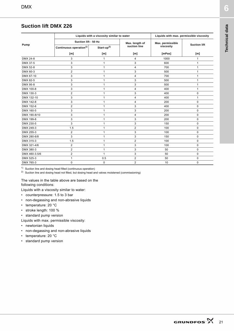
Suction lift DMX 226
1) Suction line and dosing head filled (continuous operation)2) Suction line and dosing head not filled, but dosing head and valves moistened (commissioning)
The values in the table above are based on the following conditions:
Liquids with a viscosity similar to water:
• counterpressure: 1.5 to 3 bar
• non-degassing and non-abrasive liquids
• temperature: 20 °C
• stroke length: 100 %
• standard pump version
Liquids with max. permissible viscosity:
• newtonian liquids
• non-degassing and non-abrasive liquids
• temperature: 20 °C
• standard pump version
Pump
Liquids with a viscosity similar to water Liquids with max. permissible viscosity
Suction lift - 50 Hz Max. length of suction line
Max. permissible viscosity
Suction liftContinuous operation1) Start-up2)
[m] [m] [m] [mPas] [m]
DMX 24-8 3 1 4 1000 1
DMX 37-5 3 1 3 600 1
DMX 52-8 3 1 4 700 1
DMX 60-3 2 1 3 500 1
DMX 67-10 3 1 4 700 1
DMX 82-5 3 1 3 500 1
DMX 95-8 3 1 3 500 1
DMX 100-8 3 1 4 400 1
DMX 130-3 2 1 3 400 0
DMX 132-10 3 1 4 400 1
DMX 142-8 3 1 4 200 0
DMX 152-6 2 1 3 400 0
DMX 160-5 3 1 3 200 0
DMX 190-8/10 3 1 4 200 0
DMX 199-8 3 1 3 200 0
DMX 230-5 3 1 3 150 0
DMX 249-3 1.5 1 2 100 0
DMX 255-3 2 1 3 100 0
DMX 280-6/8 3 1 3 150 0
DMX 315-3 1.5 1 2 100 0
DMX 321-4/6 2 1 3 100 0
DMX 380-3 2 1 3 50 0
DMX 460-3.5/6 2 1 3 50 0
DMX 525-3 1 0.5 2 50 0
DMX 765-3 0 0 2 10 0
21

Te
ch
nic
al d
ata
22
DMX6
Suction lift DMX 227
1) Suction line and dosing head filled (continuous operation)2) Suction line and dosing head not filled, but dosing head and valves moistened (commissioning)
The values in the table above are based on the following conditions:
Liquids with a viscosity similar to water:
• counterpressure: 1.5 to 3 bar
• non-degassing and non-abrasive liquids
• temperature: 20 °C
• stroke length: 100 %
• standard pump version
Liquids with max. permissible viscosity:
• newtonian liquids
• non-degassing and non-abrasive liquids
• temperature: 20 °C
• standard pump version
Pump
Liquids with a viscosity similar to water Liquids with max. permissible viscosity
Suction lift - 50 Hz Max. length of suction line
Max. permissible viscosity
Suction liftContinuous operation1) Start-up2)
[m] [m] [m] [mPas] [m]
DMX 430-5 3 1 3 1000 0
DMX 770-3 3 1 2 800 0
DMX 860-5 3 1 3 800 0
DMX 1120-5 3 1 3 400 0
DMX 1520-3 3 1 2 400 0
DMX 2000-3 3 1 2 200 0

Te
ch
nic
al
da
ta
DMX 6
Weights DMX 221
The weights are approximate.
Weights DMX 226
The weights are approximate.
Weights DMX 227
The weights are approximate.
Sound pressure
* Tested according to DIN 45635-01-KL3.
Accuracy
The values in the table above are based on the following conditions:
• dosing liquid: water
• fully vented dosing head
• standard version of pump.
Permissible temperature of dosing liquid
* For SIP/CIP applications, a temperature of 145 °C is permissible for a short time (approx. 15 min.) at p < 2 bar.(CIP = Cleaning-In-Place).(SIP = Sterilisation/Steaming-In-Place).
PumpWeights [kg]
Plastics Stainless steel
DMX 4-10 5 7
DMX 7-10 5 7
DMX 8-10 5 7
DMX 9-10 5 7
DMX 12-10 5 7
DMX 14-10 5 7
DMX 16-10 5 7
DMX 17-4 7.5 12
DMX 18-10 5 7
DMX 25-3 8 13
DMX 26-10 5 7
DMX 27-10 5 7
DMX 35-10 5 7
DMX 39-4 7.5 12
DMX 50-10 5 7
DMX 60-3 8 13
DMX 75-4 7.5 12
DMX 115-3 8 13
Pump
Weights [kg]
Single-head pump Double-head pump
PVCStainless
steelPVC
Stainless steel
DMX 24-8 15 21 24 36
DMX 37-5 15 21 24 36
DMX 52-8 15 21 24 36
DMX 60-3 15 21 24 36
DMX 67-10 21 30 30 48
DMX 82-5 15 21 24 36
DMX 95-8 21 30 30 48
DMX 100-8 15 21 24 36
DMX 130-3 15 21 24 36
DMX 132-10 21 30 30 48
DMX 142-8 15 21 24 36
DMX 152-6 21 30 30 48
DMX 160-5 15 21 24 36
DMX 190-8/10 21 30 30 48
DMX 199-8 21 30 30 48
DMX 230-5 15 21 24 36
DMX 249-3 21 30 30 48
DMX 255-3 15 21 24 36
DMX 280-6/8 21 30 30 48
DMX 315-3 21 30 30 48
DMX 321-4/6 21 30 30 48
DMX 380-3 15 21 24 36
DMX 460-3.5/6 21 30 30 48
DMX 525-3 21 30 30 48
DMX 765-3 21 30 30 48
Pump
Weights [kg]
Single-head pump Double-head pump
PlasticsStainless
steelPlastics
Stainless steel
DMX 430-5 69 93 122 175
DMX 770-3 69 93 122 175
DMX 860-5 69 93 122 175
DMX 1120-5 69 93 122 175
DMX 1520-3 69 93 122 175
DMX 2000-3 69 93 122 175
Pump rangeSound pressure level*
[dB(A)]
DMX 221 55
DMX 226 55
DMX 227 70
Dosing flow fluctuation Linearity deviation
< ± 1.5 % within the 10 to 100 % control range
• ± 4 % of full scale value within the 20 to 100 % control range;
• direction of adjustment from maximum to minimum stroke length.
Dosing head material
Permissible temperature of dosing liquid
p < 10 bar[°C]
PVC 0 to 40
Stainless steel 1.4571 to EN 10027-2 (SS316Ti)*
- 10 to 70
PP 0 to 40
PVDF- 10 to 60
(70 °C at 9 bar)
23

Se
lec
tion
of p
um
p
24
DMX7
7. Selection of pump
DMX 221 standard range (4 to 115 l/h)
DMX 226 M standard range (24 to 380 l/h)
Max. flow [l/h]
Max.pressure
[bar]
Material
Connection Type designationProductnumberPump
headGasket
Valve ball
4 10PVC FKM Glass PVC 6/12 mm hose, 10/12 mm pipe DMX 4-10 B-PVC/V/G-X-E1B1B1 96684148
SS PTFE SS 1/4" female DMX 4-10 B-SS/T/SS-X-E1AA 96716307
7 10PVC FKM Glass PVC 6/12 mm hose, 10/12 mm pipe DMX 7-10 B-PVC/V/G-X-E1B1B1 96730998
SS PTFE SS 1/4" female DMX 7-10 B-SS/T/SS-X-E1AA 96684430
14 10PVC FKM Glass PVC 6/12 mm hose, 10/12 mm pipe DMX 14-10 B-PVC/V/G-X-E1B1B1 96693593
SS PTFE SS 1/4" female DMX 14-10 B-SS/T/SS-X-E1AA 96683666
27 10PVC FKM Glass PVC 6/12 mm hose, 10/12 mm pipe DMX 27-10 B-PVC/V/G-X-E1B1B1 96648142
SS PTFE SS 1/4" female DMX 27-10 B-SS/T/SS-X-E1AA 96715842
35 10PVC FKM Glass PVC 6/12 mm hose, 10/12 mm pipe DMX 35-10 B-PVC/V/G-X-E1B1B1 96650928
SS PTFE SS 1/4" female DMX 35-10 B-SS/T/SS-X-E1AA 96684076
50 10PVC FKM Glass PVC 6/12 mm hose, 10/12 mm pipe DMX 50-10 B-PVC/V/G-X-E1B1B1 96611961
SS PTFE SS 1/4" female DMX 50-10 B-SS/T/SS-X-E1AA 96684272
75 4PVC FKM Glass PVC 13/20 mm hose, 20/25 mm pipe DMX 75-4 B-PVC/V/G-X-E1B2B2 96652050
SS PTFE SS 3/4" female DMX 75-4 B-SS/T/SS-X-E1A1A1 96684507
115 3PVC FKM Glass PVC 13/20 mm hose, 20/25 mm pipe DMX 115-3 B-PVC/V/G-X-E1B2B2 96611663
SS PTFE SS 3/4" female DMX 115-3 B-SS/T/SS-X-E1A1A1 96683528
Max. flow [l/h]
Max.pressure
[bar]
Material
Connection Type designationProductnumberPump
headGasket
Valve ball
24 8PVC FKM Glass PVC 13/20 mm hose, 20/25 mm pipe DMX 24-8 B-PVC/V/G-X-E1B2B2 96685432
SS PTFE SS 3/4" female DMX 24-8 B-SS/T/SS-X-E1A1A1 96718926
100 8PVC FKM Glass PVC 13/20 mm hose, 20/25 mm pipe DMX 100-8 B-PVC/V/G-X-E1B2B2 96717563
SS PTFE SS 3/4" female DMX 100-8 B-SS/T/SS-X-E1A1A1 96684911
142 8PVC FKM Glass PVC 13/20 mm hose, 20/25 mm pipe DMX 142-8 B-PVC/V/G-X-E1B2B2 96685051
SS PTFE SS 3/4" female DMX 142-8 B-SS/T/SS-X-E1A1A1 96718050
224 5PVC FKM Glass PVC 13/20 mm hose, 20/25 mm pipe DMX 230-5 B-PVC/V/G-X-E1B2B2 96634523
SS PTFE SS 3/4" female DMX 230-5 B-SS/T/SS-X-E1A1A1 96691542
380 3PVC FKM Glass PVC hose 19/27 mm DMX 380-3 B-PVC/V/G-X-E1B9B9 96653406
SS PTFE SS 3/4" female DMX 380-3 B-SS/T/SS-X-E1A1A1 96615372
Se
lec
tio
n o
f p
um
p
DMX 7
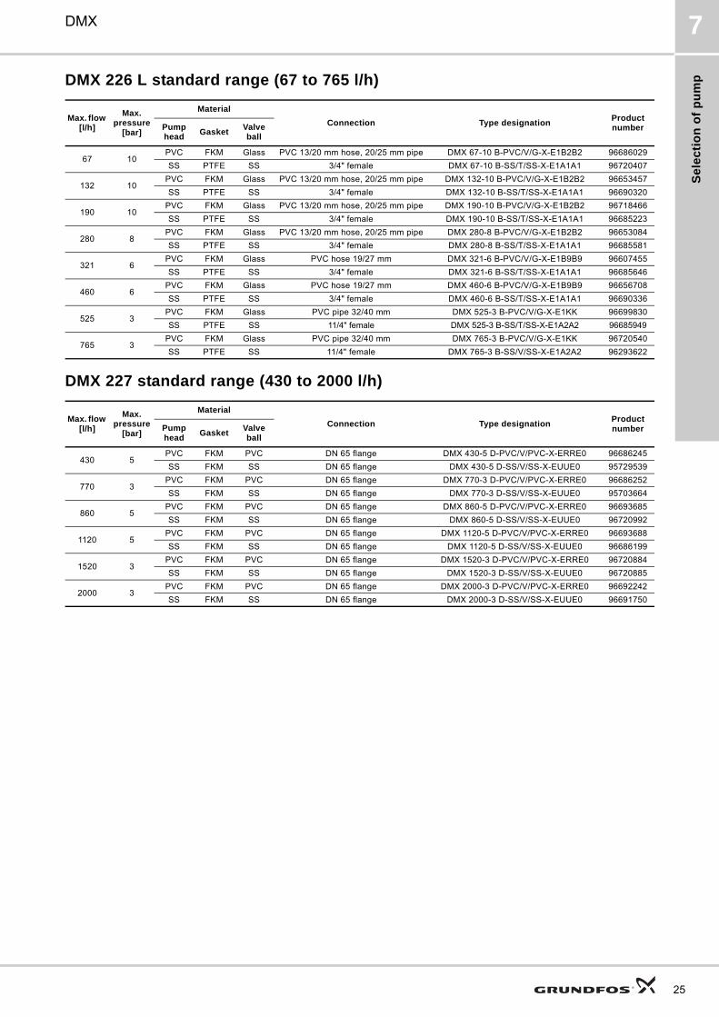
DMX 226 L standard range (67 to 765 l/h)
DMX 227 standard range (430 to 2000 l/h)
Max. flow [l/h]
Max.pressure
[bar]
Material
Connection Type designationProductnumberPump
headGasket
Valve ball
67 10PVC FKM Glass PVC 13/20 mm hose, 20/25 mm pipe DMX 67-10 B-PVC/V/G-X-E1B2B2 96686029
SS PTFE SS 3/4" female DMX 67-10 B-SS/T/SS-X-E1A1A1 96720407
132 10PVC FKM Glass PVC 13/20 mm hose, 20/25 mm pipe DMX 132-10 B-PVC/V/G-X-E1B2B2 96653457
SS PTFE SS 3/4" female DMX 132-10 B-SS/T/SS-X-E1A1A1 96690320
190 10PVC FKM Glass PVC 13/20 mm hose, 20/25 mm pipe DMX 190-10 B-PVC/V/G-X-E1B2B2 96718466
SS PTFE SS 3/4" female DMX 190-10 B-SS/T/SS-X-E1A1A1 96685223
280 8PVC FKM Glass PVC 13/20 mm hose, 20/25 mm pipe DMX 280-8 B-PVC/V/G-X-E1B2B2 96653084
SS PTFE SS 3/4" female DMX 280-8 B-SS/T/SS-X-E1A1A1 96685581
321 6PVC FKM Glass PVC hose 19/27 mm DMX 321-6 B-PVC/V/G-X-E1B9B9 96607455
SS PTFE SS 3/4" female DMX 321-6 B-SS/T/SS-X-E1A1A1 96685646
460 6PVC FKM Glass PVC hose 19/27 mm DMX 460-6 B-PVC/V/G-X-E1B9B9 96656708
SS PTFE SS 3/4" female DMX 460-6 B-SS/T/SS-X-E1A1A1 96690336
525 3PVC FKM Glass PVC pipe 32/40 mm DMX 525-3 B-PVC/V/G-X-E1KK 96699830
SS PTFE SS 11/4" female DMX 525-3 B-SS/T/SS-X-E1A2A2 96685949
765 3PVC FKM Glass PVC pipe 32/40 mm DMX 765-3 B-PVC/V/G-X-E1KK 96720540
SS PTFE SS 11/4" female DMX 765-3 B-SS/V/SS-X-E1A2A2 96293622
Max. flow [l/h]
Max.pressure
[bar]
Material
Connection Type designationProductnumberPump
headGasket
Valve ball
430 5PVC FKM PVC DN 65 flange DMX 430-5 D-PVC/V/PVC-X-ERRE0 96686245
SS FKM SS DN 65 flange DMX 430-5 D-SS/V/SS-X-EUUE0 95729539
770 3PVC FKM PVC DN 65 flange DMX 770-3 D-PVC/V/PVC-X-ERRE0 96686252
SS FKM SS DN 65 flange DMX 770-3 D-SS/V/SS-X-EUUE0 95703664
860 5PVC FKM PVC DN 65 flange DMX 860-5 D-PVC/V/PVC-X-ERRE0 96693685
SS FKM SS DN 65 flange DMX 860-5 D-SS/V/SS-X-EUUE0 96720992
1120 5PVC FKM PVC DN 65 flange DMX 1120-5 D-PVC/V/PVC-X-ERRE0 96693688
SS FKM SS DN 65 flange DMX 1120-5 D-SS/V/SS-X-EUUE0 96686199
1520 3PVC FKM PVC DN 65 flange DMX 1520-3 D-PVC/V/PVC-X-ERRE0 96720884
SS FKM SS DN 65 flange DMX 1520-3 D-SS/V/SS-X-EUUE0 96720885
2000 3PVC FKM PVC DN 65 flange DMX 2000-3 D-PVC/V/PVC-X-ERRE0 96692242
SS FKM SS DN 65 flange DMX 2000-3 D-SS/V/SS-X-EUUE0 96691750
25

Se
lec
tion
of p
um
p
26
DMX7
DMX non-standard range (4 to 2 x 765 l/h)For further information about type codes see type keys in chapter “Identification” on page 6.
Max. flow & press. [l/h]-[bar]
Control variantMaterials Control
panel position
Supply voltage
Valve type
Connectionsuction/discharge
Mains plug
Motor variantHead Gaskets Balls
DMX 221, DN 8, possible variants
4-107-108-109-10
12-1014-1016-1018-1026-1027-1035-1050-10
BARAT3AT5AT8AT9
PP
E
C
SXFW
GHE
134
4466
A9A9B1B1B3B3
SS
FBIEX
E0E1 (no ATEX)E2 (no ATEX)
SS
T
V
C
G
T
PVT
C
T
V T
PVC
E
C
SS
T
TC
T
V
C
G
SS
SS
T SSSXFW
GHE
134
AAA9A9
VV
FBIEX
E0E1 (no ATEX)E2 (no ATEX)
V SS
DMX 221, DN 20, possible variants
17-425-339-460-375-4115-3
BARAT3AT5
PP
ESS
XFW
GHE
134
A7A7B2B2B4B4B9B9QQ
FBIEX
E0E1 (no ATEX)E2 (no ATEX)
T
T T
V G
PTFE T C
PV T T
PVC
ESS
T
T C
V
C
G
SS
SS
T SSXFW
GHE
134
A1A1A3A3
FBIEX
E0E1 (no ATEX)E2 (no ATEX)
V SS
DMX 226, DN 20, possible variants
24-837-552-860-3
67-1082-595-8
100-8130-3
132-10142-8152-6160-5
190-10199-8230-5255-3280-8315-3321-6380-3460-6
BARAT3AT5AT8AT9
PP
ESS
SXFW
0GHEF
134
A7A7B2B2B4B4B9B9QQ
FBIEX
E0E1 (ATEX)E2 (ATEX)
T
T T
V G
PVT T
V T
PVC
ESS
T
T C
V
C
G
SS
SS
T SSSXFW
0GHEF
134
A1A1A3A3
FBIEX
E0E1 (ATEX)E2 (ATEX)V SS

Se
lec
tio
n o
f p
um
p
DMX 7
* According to EN 10027-2** Not available with single-phase motor and therefore not with control variant AR.
Note:
Mains plug only for single phase.
DMX model 226 and 227 are available with two dosing heads.
DMX 226, DN 32, possible variants
249-3525-3
765-3**
BARAT3AT5AT8AT9
PPE T
SXFW
0GHEF
134
A8A8B5B5
KK
BEFIX
E0E1 (ATEX)E2 (ATEX)
V G
PV T T
PVCE SS
V G
SS
E SSSXFW
0GHEF
134
A2A2A4A4
BEFIX
E0E1 (ATEX)E2 (ATEX)
T SS
V SS
DMX 227, possible variants
430-5770-3860-51120-51520-32000-3
B
PP V PP
0F
2
RRTTUUYYZZ
E0E6
PVCV PVC
E PVC
SS V SS
Max. flow & press. [l/h]-[bar]
Control variantMaterials Control
panel position
Supply voltage
Valve type
Connectionsuction/discharge
Mains plug
Motor variantHead Gaskets Balls
27

Ac
ce
ss
orie
s
28
DMX8
8. Accessories
Overview of a dosing systemGrundfos offers a comprehensive range of accessories covering every need when dosing with Grundfos dosing pumps.
Fig. 21 Overview of dosing system
For more information about these and further accessories see separate Data Booklet Pump accessories.
TM
03
21
24
18
11
1
2
3
4 5
6
79
10
8
Pos. Description
1 Dosing tank
2 Electric agitator
3 Extraction device
4 Pulsation damper, suction side
5 Dosing pump
6 Pressure relief valve
7 Pressure loading valve
8 Pulsation damper, discharge side
9 Flow meter
10 Injection unit

Pu
mp
ed
liq
uid
s
DMX 9
9. Pumped liquids
List of pumped liquidsThis resistance table is intended to serve as a general guide only for material resistance (at room temperature) and is not a substitute for actual testing of the chemicals and pump materials under specific working conditions.
The data shown is based upon information from various sources available, but be aware that many factors, such as purity, temperature, abrasive particles, etc. can affect the chemical resistance of a given material.
Note: Some of the liquids in this table may be toxic, corrosive or hazardous.
Note: Be careful when handling these liquids.
* according to EN 10027-2
Pumped liquid (20 °C)Material
Dosing head Gasket Ball
DescriptionChemical formula
Concentration [%]
PP
PV
DF
SS
1.4
57
1*
(SS
31
6T
i)
PV
C
FK
M
EP
DM
PT
FE
Ce
ram
ic
Gla
ss
Acetic acid CH3COOH
25 – 60 – 85 – – –
Aluminium chloride AlCl3 40 – Aluminium sulphate Al2(SO4)3 60 –Ammonia, aqueous NH4OH 28 – –Calcium hydroxide5 Ca(OH)2 Calcium hypochlorite Ca(OCl)2 20 –
Chromic acid3 H2CrO4
10 30 – – 50 – – –
Copper sulphate CuSO4 30 Ferric chloride1 FeCl3 100 – Ferric sulphate1 Fe2(SO4)3 100 Ferrous chloride FeCl2 100 – Ferrous sulphate FeSO4 50 Fluosilicic acid H2SiF6 40 – –
Hydrochloric acid HCl< 25 –
25-37 – Hydrogen peroxide H2O2 30
Nitric acid HNO3
10 30 40 – 70 – – –
Peracetic acid CH3COOOH 5-15 – Potassium hydroxide KOH 50 – – –Potassium permanganate KMnO4 10 Sodium chlorate NaClO3 30 Sodium chloride NaCl 30 – Sodium chlorite NaClO2 20 –
Sodium hydroxide NaOH
20 –30 –50 – –
Sodium hypochlorite NaOCl 12-15 – – Sodium sulphide Na2S 30 –Sodium sulphite Na2SO3 20 –Sodium thiosulfate Na2S2O3 10 Sulphurous acid H2SO3 6
Sulphuric acid2 H2SO4
< 80 – 80-96 – – –
98 – – – – Resistant 1 Risk of crystallisation
2 Reacts violently with water and generates much heat (pump should be absolutely dry before dosing sulphuric acid)3 Must be fluoride-free when glass balls are used5 Once the pump is stopped, calcium hydroxide will sediment rapidly6 Not resistant for sodium hypochlorite generated on site
Limited resistance
– Not resistant
29

Fu
rthe
r pro
du
ct d
oc
um
en
tatio
n
30
DMX10
10. Further product documentation
WebCAPSWebCAPS is a Web-based Computer Aided Product Selection program available on www.grundfos.com.
WebCAPS contains detailed information on more than 185 000 Grundfos products in more than 20 languages.
In WebCAPS, all information is divided into 6 sections:
• Catalogue
• Literature
• Service
• Sizing
• Replacement
• CAD drawings.
Catalogue
With a starting point in areas of applications and pump types, this section contains • technical data• curves (QH, Eta, P1, P2, etc) which can be adapted to the
density and viscosity of the pumped liquid and show the number of pumps in operation
• product photos• dimensional drawings• wiring diagrams• quotation texts, etc.
Literature
In this section you can access all the lastest documents of a given pump, such as• data booklets• Installation and operating instructions• service documentation, such as Service kit catalogue and
Service kit instructions• quick guides• product brochures, etc.
Service
This section contains an easy-to-use interactive service catalogue. Here you can find and identify service parts of both existing and cancelled Grundfos pumps.Furthermore, this section contains service videos showing you how to replace service parts.
Fu
rth
er
pro
du
ct
do
cu
me
nta
tio
n
DMX 10
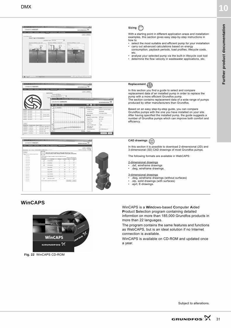
WinCAPS
Fig. 22 WinCAPS CD-ROM
WinCAPS is a Windows-based Computer Aided Product Selection program containing detailed informtion on more than 185,000 Grundfos products in more than 22 languages.
The program contains the same features and functions as WebCAPS, but is an ideal solution if no Internet connection is available.
WinCAPS is available on CD-ROM and updated once a year.
Sizing
With a starting point in different application areas and installation examples, this section gives easy step-by-step instructions in how to• select the most suitable and efficient pump for your installation• carry out advanced calculations based on energy
consumption, payback periods, load profiles, lifecycle costs, etc.
• analyse your selected pump via the built-in lifecycle cost tool• determine the flow velocity in wastewater applications, etc.
Replacement
In this section you find a guide to select and compare replacement data of an installed pump in order to replace the pump with a more efficient Grundfos pump. The section contains replacement data of a wide range of pumps produced by other manufacturers than Grundfos.
Based on an easy step-by-step guide, you can compare Grundfos pumps with the one you have installed on your site. After having specified the installed pump, the guide suggests a number of Grundfos pumps which can improve both comfort and efficiency.
CAD drawings
In this section it is possible to download 2-dimensional (2D) and 3-dimensional (3D) CAD drawings of most Grundfos pumps.
The following formats are available in WebCAPS:
2-dimensional drawings• .dxf, wireframe drawings• .dwg, wireframe drawings.
3-dimensional drawings• .dwg, wireframe drawings (without surfaces)• .stp, solid drawings (with surfaces)• .eprt, E-drawings.
0 1
Subject to alterations.
31
GRUNDFOS A/S . DK-8850 Bjerringbro . DenmarkTelephone: +45 87 50 14 00www.grundfos.com
The name Grundfos, the Grundfos logo, and the payoff Be–Think–Innovate are registrated trademarks owned by Grundfos Management A/S or Grundfos A/S, Denmark. All rights reserved worldwide.
Being responsible is our foundationThinking ahead makes it possible
Innovation is the essence
95724361 0811
GBRepl. 96609195 0806 96735225 0307
ECM: 1070848