GRU-4 - 44375 (WIKA) · 2 table of contents section 1 general information section 2 important...
35
1 User Manual GFU10 In order to avoid operating errors, please read this user manual thoroughly before use. The manufacturer assumes no liability for product misuse, which also voids the warranty. WIKA Alexander Wiegand GmbH Alexander Wiegand Strasse 63820 Klingenberg Germany Phone: +49 9372 / 132 - 8971 E-Mail: [email protected] Internet: www.wika.de/sf6
Transcript of GRU-4 - 44375 (WIKA) · 2 table of contents section 1 general information section 2 important...

1
User Manual
GFU10
In order to avoid operating errors, please read this user manual thoroughly before use. The manufacturer assumes no liability for product misuse, which also voids the warranty.
WIKA Alexander Wiegand GmbH Alexander Wiegand Strasse 63820 Klingenberg Germany Phone: +49 9372 / 132 - 8971 E-Mail: [email protected] Internet: www.wika.de/sf6

2
TABLE OF CONTENTS
SECTION 1 GENERAL INFORMATION
SECTION 2 IMPORTANT SAFETY AND TRANSPORTATION INSTRUCTIONS
SECTION 3 EVACUATION OF THE GFU10
SECTION 4 RECOVERING SF6 FROM EQUIPMENT
SECTION 5 PURIFYING SF6 BY RE-CIRCULATING IN THE GFU10
SECTION 6 EVACUATING THE EQUIPMENT
SECTION 7 CHARGING THE EQUIPMENT WITH SF6
SECTION 8 USING THE OPTIONAL TANK HEATER
SECTION 9 MAINTENANCE
SECTION 10
TROUBLESHOOTING
SECTION 11
PHYSICAL PROPERTIES OF SF6
SECTION 12
LIST OF COMPONENTS
SECTION 13
DRAWINGS
MANUFACTURER’S INSTRUCTIONS FOR COMPONENTS ARE LOCATED ON THE CD
3
SECTION 1 – GENERAL INFORMATION
1.1 INTRODUCTION
Congratulations on purchasing the best portable SF6 maintenance unit available. Please take a few moments to read through this manual and become familiar with the operation and maintenance of the GFU10.
1.2 PROCESS
Using oil-less compressors, the GFU10 can recover, purify and charge the SF6 gas in your equipment. The GFU10 oil-less compressors, under normal operating conditions, can liquefy SF6 gas during recovery. This allows for more SF6 to be temporarily stored on the unit than if it remained in a gas state. The compressor can also draw a vacuum on the equipment while pumping against high pressures. This allows more SF6 to be recovered and stored for purification and re-use. The ability to produce high pressures also gives the GFU10 the ability to consolidate and fill the SF6
cylinders.
1.3 STANDARD FEATURES
Standard features include:
Spin-on inlet and outlet drier/filter cartridge, (D-1), to remove moisture, (to -49°F/-45°C dew point), and particles to 5 micron.
Spin-on purification filter, (P-1), to remove lower fluorides of
sulphur which are produced by arcing.
Spin-on particulate filter, (F-1), to filter SF6 to 0.1 micron nominal.
Inlet and outlet moisture indicators. The indicators will be light green if the water content of the gas is below 40 ppmw, or will be yellow if the water content is above 100 ppmw.
Compressor running time counter to track operation and plan
maintenance.
High pressure storage tank with level switch and relief valve to temporarily store 50 lb, (18 kg), of gas at 70°F, (21°C), tank temperature.
An auxiliary valve, (V-5), to connect an SF6 cylinder or similar
storage vessel. V-5 can also be used as a sample port for connecting a hygrometer.
Automatic shutdown on high pressure with indicating light.

4
SECTION 1 – GENERAL INFORMATION FIGURE 1 REAR VIEW OF GFU10
FIGURE 2 ONBOARD STORAGE TANK VALVES
5
SECTION 2 – IMPORTANT SAFETY AND TRANSPORTATION INSTRUCTIONS
2.1 IMPORTANT SAFETY INFORMATION
Prior to shipment, the GFU10 is filled with dry nitrogen to 5-psig/0.3
bar to keep out moisture. Before the first use, the GFU10 should be evacuated to less than 29.9 “Hg using the vacuum pump. This process is described in the following section.
The GFU10 is capable of producing very high pressures. Wear
protective equipment when connecting and disconnecting hoses. Venting gas can cause frostbite and/or cold burns if it comes into contact with exposed skin. All hoses, external storage vessels, fittings and connectors must be rated for at least 500psig/35 bar. Do not attempt to service the unit while under pressure.
Do not store SF6 in the onboard tank. This tank is for temporary
storage only while servicing the equipment. All auxiliary storage vessels must be designed for at least 500 psig/35 bar with a DOT or ASME approved design. Do not attempt to recover into or fill a non-refillable tank.
The GFU10 is designed for use with SF6 only. Use with other gases
may damage components or cause injury.
2.2 OPERATING GUIDELINES
Always use a pressure gauge mounted directly on the equipment
being serviced. The readings of the GFU10 gauges will not show pressure drop and/or temperature variation between the unit and the equipment.
Do not connect or disconnect hoses at pressures above 100
psig/6.9 bar. Doing so will reduce the life of the internal seals in the quick connect fittings. Replace worn or damaged hoses immediately.
De-pressurize hoses before attaching to the vacuum connection on
the GFU10.
Disconnect all power supplies before servicing. Replace worn and/or damaged power cords immediately.
6
SECTION 2 – IMPORTANT SAFETY AND TRANSPORTATION INSTRUCTIONS
2.3 CARE AND TRANSPORTATION INSTRUCTIONS
Remove as much gas from the GFU10 as possible. Do not
transport SF6 in the storage tank.
Equalise the remaining gas by opening and closing valves V-1, V-2, V-3, and V-4. Make sure the pressure readings on the “Suction”, “Discharge” and “Regulated” gauges are less than 30-psig/2.0 bar.
Close all valves.
Store all hoses and power cables securely.
The preferred method of shipping the GFU10 is in the upright
position.
If you must transport in the laid down position, drain out the vacuum pump oil and close the vacuum pump ISO-VALVE to prevent oil seepage.
Keep the GFU10 out of wet and damp locations.
Do not store in direct sunlight.
Cover the unit if storing for extended periods.
7
SECTION 3 – EVACUATION OF THE GFU10
3.1 INTRODUCTION
The GFU10 is shipped from the factory with approximately 5psig/0.3 bar of dry nitrogen in the system. Before using the first time, it is necessary to remove the nitrogen and evacuate the GFU10 to below 29.9” Hg vacuum. Please read the operating manual for the vacuum pump, located on the CD, before continuing.
3.2 PROCESS
1) Close all valves.
2) Check oil level in vacuum pump.
3) Plug the vacuum pump cord into an appropriate power supply,
(see nameplate for more information).
4) Connect one end of the equipment hose to valve V-5.
5) Open valves V-3 and V-4
6) Turn the valve V-1 and V-2 to the “Purify” positions (both pointing up).
7) Depress the end of the equipment hose quick connector with a
small screwdriver to allow any pressure in the system to vent to atmosphere.
8) Once all pressure has been removed, connect the hose end to
the vacuum connection. There should now be a hose connected between valve V-5 and the vacuum connection on the panel.
9) Open valve V-5.
10) Start the vacuum pump.
11) Evacuate the unit for at least 30 minutes.
12) Turn the valve “V-1” to the “Recover” position, (pointing down).
13) Evacuate for 5 more minutes.
14) Close all valves.
8
SECTION 3 - EVACUATION OF THE GFU10
3.2 PROCESS Continued..
15) Disconnect the hose from the vacuum pump connection.
16) Turn off the vacuum pump.
**NOTE: If the power fails while the vacuum pump is running, the Anti Oil Return Solenoid valve will close, preventing oil from being drawn from the vacuum pump into the GFU10 or the equipment being evacuated.

9
SECTION 4 – RECOVERING SF6 FROM EQUIPMENT
4.1 INTRODUCTION
Read the previous section before starting this operation. To maintain purity of the gas, it is strongly recommended that you evacuate the GFU10, (to 29.9” Hg), along with any hoses and/or vessels you may be using to store or transfer the gas. Close all valves before continuing.
4.2 RECOVERING SF6
1) Plug the GFU10 power cord into a suitable power supply, (see
nameplate for more information). 2) Connect one end of the equipment hose to the “Equipment
Connection” on the operator panel. Connect the other end of the hose to your equipment.
3) If you are recovering gas into the onboard tank, open valve V-4. If
you are recovering gas into an external storage tank, connect this tank via hose to the valve V-5 on the operator panel.
4) Open valve V-5 and the valve on the external storage vessel, (V-4
should remain closed when V-5 is open).
5) Turn valve V-1 into the “Recover” position, (down). Turn valve V-2 into the “Recover” position, (up).
6) Press the “START” button on the operator panel. The compressor
will come on, drawing from the “Equipment Connection”, through the filters and through either valve V-4 or V-5.
7) The GFU10 will continue to run until you press the “STOP” button,
or if “High Pressure” or “Tank Full” is encountered. **NOTE: You can monitor the recovery process by watching the “Suction” gauge. When the GFU10 starts to draw a vacuum on your equipment, the needle on the “Suction” gauge will drop into the 0”-30”Hg range.
8) Once the recovery process is complete, press the “STOP” button to turn off the GFU10 compressor.
9) Close valve V-4, (or V-5 if recover was to an external vessel).
**NOTE: If the GFU10 discharge pressure exceeds 490-500 psig/33.8-35 bar, or if the level switch in the onboard tank senses a high level, the GFU10 will automatically stop. The respective warning light will come on. The GFU10 will not automatically restart if the condition is corrected.

10
SECTION 4 – RECOVERING SF6 FROM EQUIPMENT
4.3 ADDITIONAL RECOVERY HINTS
To speed recovery, cool the vessel you are recovering into with fans, ice packs etc. Keeping the recovery vessel cool lowers the pressure, increasing the flow rate of the compressor. To draw a deeper vacuum on your equipment with the GFU10 compressor, make sure the onboard tank is empty before starting the recovery process. Start recovering into an external storage vessel by following the above procedure. Once the “Suction” gauge begins to read vacuum, close valve V-5 and open valve V-4. The GFU10 will begin recovery into an empty tank, which will drop the discharge pressure considerably. This will improve the vacuum of the GFU10 can draw on your equipment. To maintain high purity gas, check and, (if necessary), change the filter elements often. The inlet drier/filter will be subject to most of the moisture and impurities from the recovered gas. Pay attention to the moisture indicator to ensure that a moisture-saturated element does not allow wet gas to continue through the system.

11
SECTION 5 – PURIFYING SF6 BY RE-CIRCULATING IN THE GFU10
5.1 PURIFYING IN THE GFU10
This operation can only be performed with the onboard GFU10 storage tank.
1) Close all valves.
2) Turn valves V-1 and V-2 into the “Purify” position (both up).
3) Open tank valves V-3 and V-4.
4) Press the “Start” button. The GFU10 will continue to purify until you stop the operation.
5) To stop the operation, first close tank valve V-3. Allow the “Suction”
gauge to drop to zero or into vacuum. Then press the “Stop” button.

12
SECTION 6 – EVACUATING THE EQUIPMENT
6.1 INTRODUCTION
The onboard vacuum pump can be used to evacuate equipment prior to charging with gas. To obtain consistent results, it is recommended that a mechanical 40-0 Torr gauge or electronic vacuum gauge be used to monitor the vacuum in the equipment. If your GFU10 is equipped with option “T”, a 40-0 Torr mechanical gauge will already be installed on the vacuum pump.
6.2 EVACUATING THE EQUIPMENT
1) Read the vacuum pump instruction manual located on the CD.
2) Plug the vacuum pump into a suitable power supply, (see
nameplate for more information).
3) Check the oil level in the vacuum pump sight glass. It should be in the centre.
4) Make sure the equipment you will be evacuating does not contain
pressure.
5) Connect a mechanical Torr gauge or electronic vacuum gauge to your equipment.
6) Connect one end of the equipment hose to your equipment, (use
of a shutoff valve is recommended).
7) Connect the other end of the equipment hose to the “Vacuum Connection” on the GFU10 operator panel.
8) Start the vacuum pump.
9) Continue to evacuate unit the equipment reaches the desired
vacuum.
10) Close shutoff valve on equipment.
11) Disconnect the hose from “Vacuum Connection” on the operator panel.
12) Shut off vacuum pump.

13
SECTION 6 – EVACUATING THE EQUIPMENT
6.3 ADDITIONAL EVACUATING HINTS
If the power fails while the vacuum pump is running, the Anti Oil Return Solenoid valve will close, preventing oil from being drawn from the pump into the GFU10 or the equipment being evacuated. **HINT: To see the vacuum drop due to possible leaks in equipment or excess moisture, close the ISO-VALVE on the vacuum pump while it is still running. This will allow the Anti Oil Return Solenoid to remain open for an accurate reading.
14
SECTION 7 – CHARGING THE EQUIPMENT WITH SF6
7.1 CHARGING THE EQUIPMENT
1) Close all valves.
2) Connect one end of equipment hose to the equipment being
charged. It is recommended that a shut-off valve and gauge be mounted on the equipment being serviced to monitor the charge process.
3) Turn valve V-1 to the “Charge” position, (up). Turn valve V-2 to the
“Charge” position, (down).
4) Open tank valve V-3. The “Suction” gauge should read approximately 30-psig/2.0 bar.
5) If you are charging from an external tank, connect the tank to V-5
on the operator panel.
6) Open the valve on the external tank, open V-5 and open V-4.
7) Set the regulator to the desired pressure, viewable on the “Regulated” gauge.
8) Connect the equipment hose to the “Equipment Connection” on the
operator panel and open the valve to the equipment. Note that as gas flows from the GFU10 into the equipment, the reading on the “Regulated” gauge will drop.
9) Press the “Start” button to turn on the GFU10 compressor.
10) Monitor pressure at the equipment on locally mounted gauge. Note
that while charging is taking place, there may be a difference between the readings of the local gauge and the “Regulated” gauge.
11) Once the desired pressure has been reached, turn off the valve on
the equipment.
12) Turn V-2 into the “Recover” position, (up).
13) Close tank valve V-3. Allow the “Suction” gauge reading to drop to zero or into slight vacuum.
14) Turn panel valve V-1 into the “Recover” position. Allow the
“Suction” gauge reading to drop to zero or into slight vacuum.
15
SECTION 7 – CHARGING THE EQUIPMENT WITH SF6
7.1 CHARGING THE EQUIPMENT Continued..
15) Turn off the compressor. 16) Close all valves.
17) Remove equipment hose from GFU10 and equipment.
18) Zero the regulator for the next use.
**NOTE: As the equipment pressure increases, the discharge pressure also rises. This happens because the GFU10 compressor begins to pump faster than gas is being transferred to the equipment. If the GFU10 shuts down on high pressure, wait a few minutes for the excess pressure to pass through the regulator into the equipment. Then restart the GFU10. **HINT: To speed charging, keep the vessel you are drawing gas from warm. This applies to the onboard tank or external vessel. See the following section for more details.
16
SECTION 8 – USING THE OPTIONAL TANK HEATER
8.1 INFORMATION
When the GFU10 is charging equipment, the storage tank becomes noticeably colder as the gas leaves. The colder temperatures reduce tank pressure and slow the charging process. The GFU10 may be purchased with an optional storage tank heater to improve the charging rate. The heater is thermostatically pre-set to approximately 120ºF/49ºC. The storage tank heater is shipped from the factory attached to the storage tank. It may be removed by removing the insulation around the tank and undoing the latch. When re-attaching the heater to the tank, make sure the fit is snug.
8.2 CARE FOR TANK HEATER
Never lift or pull the heater by its power cord
Never operate the heater if it is not securely fastened to the storage
tank.
Never operate the heater if it shows signs of damage (rips, punctures etc.)
Never touch the heater when it is plugged in
Never immerse the heater in fluids.
Allow the heater to cool down before attempting to remove it.
Be careful not to puncture or damage the heater when moving the
GFU10 or when working in proximity with tools.
Only plug the heater into a fused and grounded suitable power supply, (see nameplate for more information).

17
SECTION 9 – MAINTENANCE
9.1 EVERY USAGE
Check the level of the vacuum pump oil in the sight glass. Refer to
the vacuum pump instructions located on the CD for further information.
Check the color of the moisture indicators, (light blue indicates dry,
pink indicates wet).
9.2 EVERY 50 HOURS OF COMPRESSOR RUN TIME
Change drier cartridge, D-1. Change the purifier element, P-1. Change the filter, F-1.
9.3 EVERY 100 HOURS OF COMPRESSOR RUN TIME
Replace the piston cup and O-rings in the compressor.
9.4 CHANGING ELEMENTS
Remove as much gas from the filters as possible. Close all valves.
Install muffler or similar pressure-dispersing device on valve V-5.
Turn V-2 into the “Recover” position, (up).
Open valve V-5 to depressurize the filters.
Replace filters one at a time by unscrewing the drier cartridges and
housings. No tubing has to be removed to change filters. Inspect all seals and replace as necessary. Do NOT leave new elements exposed to atmosphere, as they will begin to absorb moisture, reducing their life.
Once elements have been changed, evacuate the filter line as
outlined in the following Section.
18
SECTION 9 – MAINTENANCE
9.5 EVACUATING THE FILTER LINE
Once elements have been changed, evacuate filter line as follows.
1) Turn the panel valve V-1 into the “Recover” position, (down).
2) Turn valve V-2 into the “Charge” position, (down).
3) Connect an equipment hose to the “Equipment Connection” on the panel.
4) Depress the connector on the free end of the hose with a small
screwdriver to make sure there is no pressure in the line.
5) Connect to the “Vacuum Connection” and start the vacuum pump.
6) Evacuate the filters for at least 30 minutes.
7) Disconnect vacuum hose when evacuation is complete
8) Re-pressurize the filters by turning valve V-2 into the “Recover”
position, (up), and slowly open valve V-4.
9) Test for leaks.
9.6 CHANGING THE PISTON CUP & O-RINGS IN COMPRESSOR
To change the piston cup and O-rings, you will require:
Replaceable parts kit Adjustable wrench
Clean tray for small parts
5/16” socket and wrench
Approximate time for this operation is about 30 to 40 minutes plus evacuation time. Keep in mind that there are several small parts in the cylinder head assembly. Take care not to lose anything.
1) De-pressurize compressor and filters as outlined earlier in the manual.

19
SECTION 9 – MAINTENANCE 9.6 CHANGING THE PISTON CUP& O-RINGS IN COMPRESSOR Continued..
2) Unplug GFU10 from power supply.
3) Remove the compressor box cover.
Use the following instructions to complete the maintenance of the compressor.
FIGURE 4 – CYLINDER HEAD TUBING
Loosen the four indicated tube nuts with a wrench. Once loose, unscrew by hand. Gently pull tubing out of the tube connectors with a slight rocking motion. ** NOTE: Be careful not to kink or flatten any tubing.**
20
SECTION 9 – MAINTENANCE
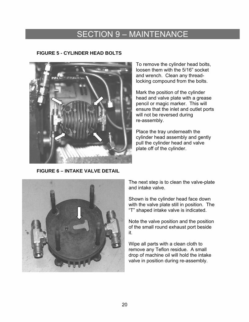
FIGURE 5 - CYLINDER HEAD BOLTS
To remove the cylinder head bolts, loosen them with the 5/16” socket and wrench. Clean any thread-locking compound from the bolts. Mark the position of the cylinder head and valve plate with a grease pencil or magic marker. This will ensure that the inlet and outlet ports will not be reversed during re-assembly. Place the tray underneath the cylinder head assembly and gently pull the cylinder head and valve plate off of the cylinder.
FIGURE 6 – INTAKE VALVE DETAIL
The next step is to clean the valve-plate and intake valve. Shown is the cylinder head face down with the valve plate still in position. The “T” shaped intake valve is indicated. Note the valve position and the position of the small round exhaust port beside it. Wipe all parts with a clean cloth to remove any Teflon residue. A small drop of machine oil will hold the intake valve in position during re-assembly.
21
SECTION 9 – MAINTENANCE
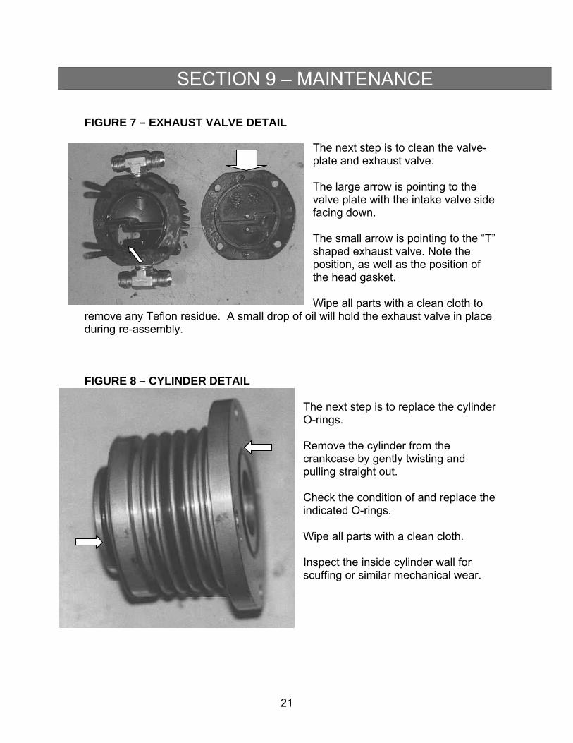
FIGURE 7 – EXHAUST VALVE DETAIL
The next step is to clean the valve-plate and exhaust valve. The large arrow is pointing to the valve plate with the intake valve side facing down. The small arrow is pointing to the “T” shaped exhaust valve. Note the position, as well as the position of the head gasket. Wipe all parts with a clean cloth to
remove any Teflon residue. A small drop of oil will hold the exhaust valve in place during re-assembly.
FIGURE 8 – CYLINDER DETAIL
The next step is to replace the cylinder O-rings. Remove the cylinder from the crankcase by gently twisting and pulling straight out. Check the condition of and replace the indicated O-rings. Wipe all parts with a clean cloth. Inspect the inside cylinder wall for scuffing or similar mechanical wear.

22
SECTION 9 – MAINTENANCE
FIGURE 9 – PISTON AND CONNECTING ROD DETAIL
The next step is to remove the piston and piston cup. The large arrow points to the (used) piston cup. The small arrow points to the top of the piston. Remove the piston with the removal tool supplied with the replacement parts kit. A properly sized pin-wrench will also work. Note that the piston cup should face forward, (pointing away from the crankcase). Wipe all parts and surfaces with a clean cloth.
FIGURE 10 – PISTON CUP DETAIL
To prepare the piston for re-assembly, follow these steps: Shown on the left is the old piston cup, in the middle is the piston, and on the right is the new piston cup. Clean any locking compound from the indicated threads on the piston.
23
SECTION 9 – MAINTENANCE
9.7 RE-ASSEMBLY OF COMPRESSOR
Assembly is the reverse of disassembly.
Remember to apply a small amount of thread locking compound on all bolts.
Make sure that the new piston cup is centered behind piston
during re-assembly.
Make sure that the intake and exhaust valves are in their proper positions
Do not over-tighten bolts during re-assembly.
It is recommended that you test the compressor before installing
the cover plates.
9.8 TESTING COMPRESSOR
WARNING: The following procedure is performed with the covers off. There is a risk of electric shock. Do not attempt this procedure if you are unfamiliar with proper test procedures. To test the operation of the compressor:
Turn all valves to closed or “OFF” position.
Plug in the GFU10 and start the compressor. The motor should start with any drag or harsh mechanical noise.
The reading on the “Suction” gauge should drop into the vacuum
range to approximately 15”Hg within the first 30 seconds of operation.
The reading on the “Discharge” gauge should rise slightly.
If the compressor cannot develop vacuum, the valves may not be
seated properly, the cylinder head may be in the wrong position, or there is a leak in the tubing. Unplug the power supply and correct the problem.
If the compressor test is successful, evacuate the GFU10 as
described earlier in this manual (if there is gas in the tank, make sure you do not open valves V-3 and V-4).
Once again unplug the GFU10.
24
SECTION 9 – MAINTENANCE
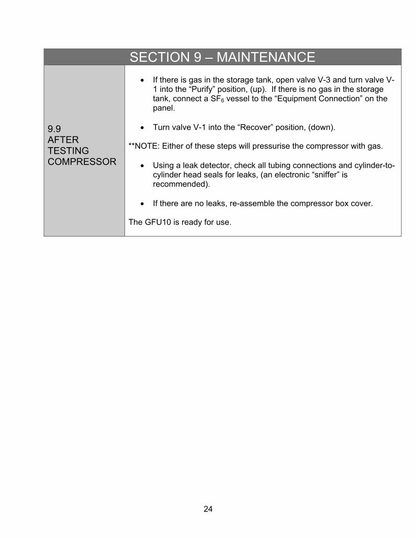
9.9 AFTER TESTING COMPRESSOR
If there is gas in the storage tank, open valve V-3 and turn valve V-
1 into the “Purify” position, (up). If there is no gas in the storage tank, connect a SF6 vessel to the “Equipment Connection” on the panel.
Turn valve V-1 into the “Recover” position, (down).
**NOTE: Either of these steps will pressurise the compressor with gas.
Using a leak detector, check all tubing connections and cylinder-to-cylinder head seals for leaks, (an electronic “sniffer” is recommended).
If there are no leaks, re-assemble the compressor box cover.
The GFU10 is ready for use.
25
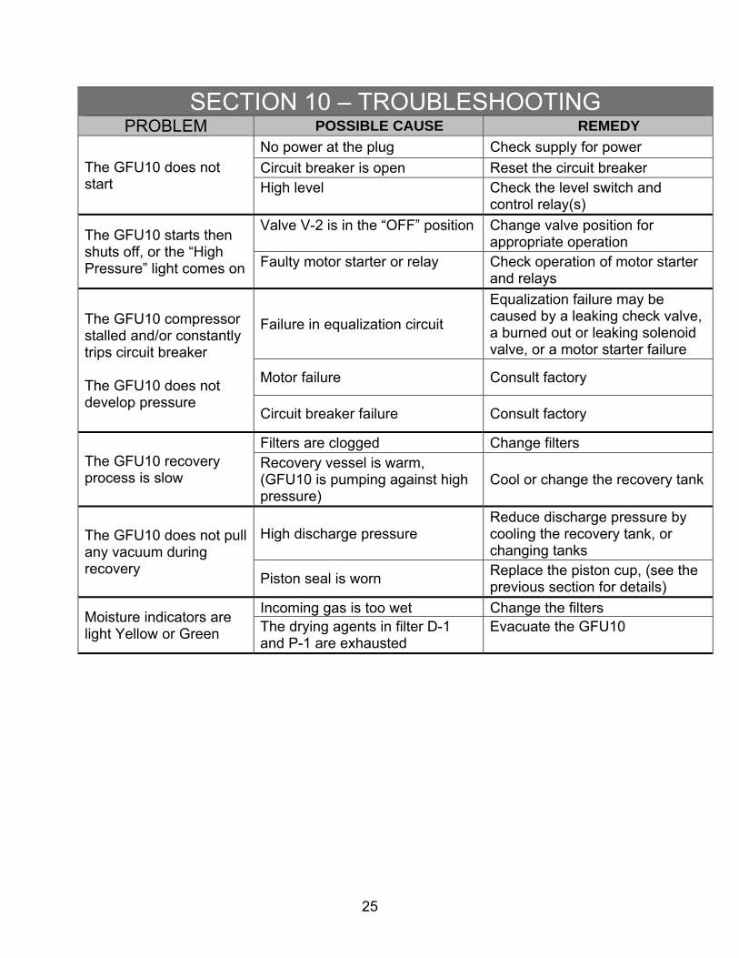
SECTION 10 – TROUBLESHOOTING PROBLEM POSSIBLE CAUSE REMEDY
The GFU10 does not start
No power at the plug Check supply for power
Circuit breaker is open Reset the circuit breaker High level Check the level switch and
control relay(s)
The GFU10 starts then shuts off, or the “High Pressure” light comes on
Valve V-2 is in the “OFF” position Change valve position for appropriate operation
Faulty motor starter or relay Check operation of motor starter and relays
The GFU10 compressor stalled and/or constantly trips circuit breaker The GFU10 does not develop pressure
Failure in equalization circuit
Equalization failure may be caused by a leaking check valve, a burned out or leaking solenoid valve, or a motor starter failure
Motor failure Consult factory
Circuit breaker failure Consult factory
The GFU10 recovery process is slow
Filters are clogged Change filters Recovery vessel is warm, (GFU10 is pumping against high pressure)
Cool or change the recovery tank
The GFU10 does not pull any vacuum during recovery
High discharge pressure Reduce discharge pressure by cooling the recovery tank, or changing tanks
Piston seal is worn Replace the piston cup, (see the previous section for details)
Moisture indicators are light Yellow or Green
Incoming gas is too wet Change the filters The drying agents in filter D-1 and P-1 are exhausted
Evacuate the GFU10

26
SECTION 11 – PHYSICAL PROPERTIES OF SF6
11.1 INTRODUCTION
Sulfur hexafluoride is a colourless, odourless gas having the following properties.
11.2 TABLE OF PROPERTIES – PHYSICAL
Formula Molecular weight Sublimation temperatures, at 1 atm °C °F Melting point, at 32.5 psia, °C °F Density of gas, at 21.1°C, 1atm, g/l at 70°F, 1 atm relative to air = 1, at 70°F, 1 atm Surface tension, at -20°C, dyne/cm Viscosity, cp liquid, at 13.52°C gas, at 31.16°C Index of refraction, at 0°C, 760 mm Hg, nD
Critical temperature, TC, °K Critical pressure, PC, bars atm Critical volume, VC, cu cm/g liters/g•mole Solubility of SF6, at 1 atm, in: transformer oil, at 27°C ml of SF6/ml oil water. At 24.85°C, cu cm SF6 (STP)/cu cm H20 Solubility of water in SF6, % by wt
SF6
146.05 -63.9 -83 -50.8 -59.4 6.139 0.382 ≈5 8.02 0.305 0.0157 1.000783 318.80 37.772 36.557 1.356 0.198 4.408 ≈0.0055 ≈0.0097
27
SECTION 11 – PHYSICAL PROPERTIES OF SF6
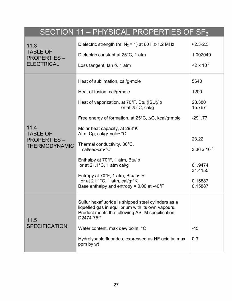
11.3 TABLE OF PROPERTIES – ELECTRICAL
Dielectric strength (rel N2 = 1) at 60 Hz-1.2 MHz Dielectric constant at 25°C, 1 atm Loss tangent. tan ô. 1 atm
≈2.3-2.5 1.002049 <2 x 10⁻⁷
11.4 TABLE OF PROPERTIES – THERMODYNAMIC
Heat of sublimation, cal/g•mole Heat of fusion, cal/g•mole Heat of vaporization, at 70°F, Btu (ISU)/lb or at 25°C, cal/g Free energy of formation, at 25°C, ∆G, kcal/g•mole Molar heat capacity, at 298°K Atm, Cp, cal/g•mole• °C Thermal conductivity, 30°C, cal/sec•cm•°C Enthalpy at 70°F, 1 atm, Btu/lb or at 21.1°C, 1 atm cal/g Entropy at 70°F, 1 atm, Btu/lb•°R or at 21.1°C, 1 atm, cal/g•°K Base enthalpy and entropy = 0.00 at -40°F
5640 1200 28.380 15.767 -291.77 23.22 3.36 x 10⁻⁵
61.9474 34.4155 0.15887 0.15887
11.5 SPECIFICATION
Sulfur hexafluoride is shipped steel cylinders as a liquefied gas in equilibrium with its own vapours. Product meets the following ASTM specification D2474-75:* Water content, max dew point, °C Hydrolysable fluorides, expressed as HF acidity, max ppm by wt
-45 0.3
28
SECTION 11 – PHYSICAL PROPERTIES OF SF6
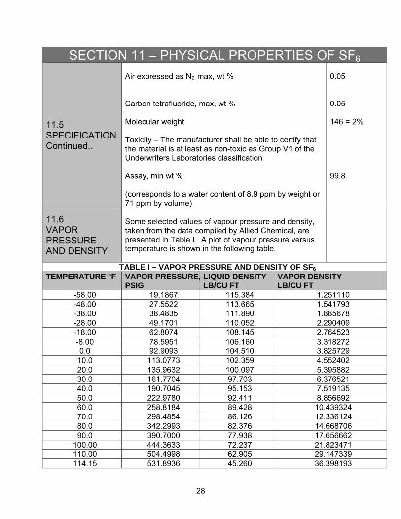
11.5 SPECIFICATION Continued..
Air expressed as N2, max, wt % Carbon tetrafluoride, max, wt % Molecular weight Toxicity – The manufacturer shall be able to certify that the material is at least as non-toxic as Group V1 of the Underwriters Laboratories classification Assay, min wt % (corresponds to a water content of 8.9 ppm by weight or 71 ppm by volume)
0.05 0.05 146 = 2%
99.8
11.6 VAPOR PRESSURE AND DENSITY
Some selected values of vapour pressure and density, taken from the data compiled by Allied Chemical, are presented in Table I. A plot of vapour pressure versus temperature is shown in the following table.
TABLE I – VAPOR PRESSURE AND DENSITY OF SF6
TEMPERATURE °F VAPOR PRESSURE,PSIG
LIQUID DENSITY LB/CU FT
VAPOR DENSITY LB/CU FT
-58.00 19.1867 115.384 1.251110 -48.00 27.5522 113.665 1.541793 -38.00 38.4835 111.890 1.885678 -28.00 49.1701 110.052 2.290409 -18.00 62.8074 108.145 2.764523 -8.00 78.5951 106.160 3.318272 0.0 92.9093 104.510 3.825729 10.0 113.0773 102.359 4.552402 20.0 135.9632 100.097 5.395882 30.0 161.7704 97.703 6.376521 40.0 190.7045 95.153 7.519135 50.0 222.9780 92.411 8.856692 60.0 258.8184 89.428 10.439324 70.0 298.4854 86.126 12.336124 80.0 342.2993 82.376 14.668706 90.0 390.7000 77.938 17.656662
100.00 444.3633 72.237 21.823471 110.00 504.4998 62.905 29.147339 114.15 531.8936 45.260 36.398193

29
SECTION 11 – PHYSICAL PROPERTIES OF SF6VAPOR PRESSURE VS TEMPERATURE – SF6

30
SECTION 12 – LIST OF COMPONENTS 12.1 GENERAL ASSEMBLY
DWG REF #: D-106308
EQUIPMENT: GFU10
DESCRIPTION PART # QUANTITY RECOMMENDED
SPARE
SYMBOL (IF ANY)
USED IN –F AND
–W DWGS
GFU10 COMPRESSOR BOX ASSEMBLY D-106309 1
GFU10 HIGH PRESSURE TANK ASSEMBLY D-104005-1 1
GFU10 MOLECULAR SIEVE ELEMENT/CANISTER
ASSEMBLY D-103514 1 1
SINGLE CORE DRIER CASE E-23199 1 D-1
¼” MOISTURE INDICATOR E-23201 1 MI-1
DRIER REPLACEMENT CORE E-23203 1
PURIFIER HOUSING, ¼” CONNECTION, 2000 PSI E-16838* 1 P-1
¾” O-RING UNION, BUNA E-14268 1
FILTER HOUSING, MINIATURE SERIES, SS E-18161 1 F-1
CARTRIDGE WITH ABSORBENT FOR SS FILTER E-18162 1 1
VACUUM PUMP 6CFM, 1/2HP, 110-115V/220-
240V/1PH-50/60HZ MOTOR E-17378* 1
¼” X 10’ FREON HOSE ASSEMBLY E-16879 2
¼” 2 WAY BRASS SOLENOID VALVE E-14948* 1
REPAIR KIT FOR E-14949 SOLENOID VALVE E-11854 1
REPLACEMENT COIL FOR E-14949 SOLENOID VALVE E-14949 1
5 AMP 250V FAST ACTING GLASS FUSE E-10683 1 1
¼” QUICK CONNECT STEM E-17157 2 1
¼” QUICK CONNECT BODY E-17159 2
*SEPARATE INSTRUCTIONS ARE LOCATED ON THE CD
31
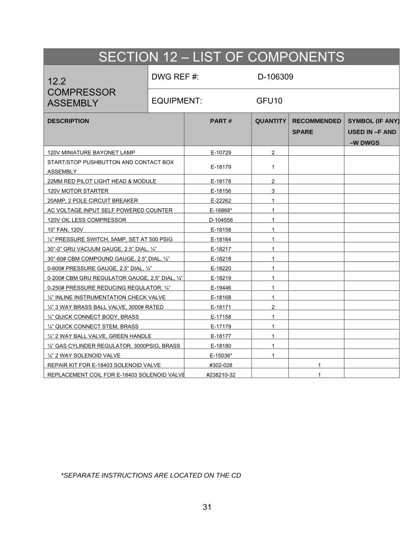
SECTION 12 – LIST OF COMPONENTS 12.2 COMPRESSOR ASSEMBLY
DWG REF #: D-106309
EQUIPMENT: GFU10
DESCRIPTION PART # QUANTITY RECOMMENDED
SPARE
SYMBOL (IF ANY)
USED IN –F AND
–W DWGS
120V MINIATURE BAYONET LAMP E-10729 2
START/STOP PUSHBUTTON AND CONTACT BOX
ASSEMBLY E-18179 1
22MM RED PILOT LIGHT HEAD & MODULE E-18178 2
120V MOTOR STARTER E-18156 3
20AMP, 2 POLE CIRCUIT BREAKER E-22262 1
AC VOLTAGE INPUT SELF POWERED COUNTER E-16868* 1
120V OIL LESS COMPRESSOR D-104556 1
10” FAN, 120V E-18158 1
¼” PRESSURE SWITCH, 5AMP, SET AT 500 PSIG E-18164 1
30”-0” GRU VACUUM GAUGE, 2.5” DIAL, ¼” E-18217 1
30”-60# CBM COMPOUND GAUGE, 2.5” DIAL, ¼” E-18218 1
0-600# PRESSURE GAUGE, 2.5” DIAL, ¼” E-18220 1
0-200# CBM GRU REGULATOR GAUGE, 2.5” DIAL, ¼” E-18219 1
0-250# PRESSURE REDUCING REGULATOR, ¼” E-19446 1
¼” INLINE INSTRUMENTATION CHECK VALVE E-18168 1
¼” 3 WAY BRASS BALL VALVE, 3000# RATED E-18171 2
¼” QUICK CONNECT BODY, BRASS E-17158 1
¼” QUICK CONNECT STEM, BRASS E-17179 1
¼” 2 WAY BALL VALVE, GREEN HANDLE E-18177 1
¼” GAS CYLINDER REGULATOR, 3000PSIG, BRASS E-18180 1
¼” 2 WAY SOLENOID VALVE E-15036* 1
REPAIR KIT FOR E-18403 SOLENOID VALVE #302-028 1
REPLACEMENT COIL FOR E-18403 SOLENOID VALVE #238210-32 1
*SEPARATE INSTRUCTIONS ARE LOCATED ON THE CD

32
SECTION 12 – LIST OF COMPONENTS 12.3 TANK ASSEMBLY
DWG REF #: D-104005-1
EQUIPMENT: GFU10
DESCRIPTION PART # QUANTITY RECOMMENDED
SPARE
SYMBOL (IF ANY)
USED IN –F AND
–W DWGS
GFU10 TANK RELIEF VALVE KIT D-104005-2 1
¾” FLOAT SWITCH, STEEL BUSHING, SS FLOAT E-18163* 1
¼” 90° ANGLE BALL VALVE – RED E-18172 1
¼” 90° ANGLE BALL VALVE – BLUE E-18173 1
*SEPARATE INSTRUCTIONS ARE LOCATED ON THE CD

33
SECTION 13 – DRAWINGS GENERAL ASSEMBLY – 106308-G

34
SECTION 13 – DRAWINGS FLOW SCHEMATIC – 106308-F

35
SECTION 13 – DRAWINGS WIRING SCHEMATIC – 103991-W