Growth of Multiple Cracks and Their Linkup in a Fuselage ... fileGrowth of Multiple Cracks and Their...
9
AIAA JOURNAL Vol. 32, No. 11, November 1994 Growth of Multiple Cracks and Their Linkup in a Fuselage Lap Joint Ripudaman Singh,* Jai H. Park,t and Satya N. Atluri$ Georgia Institute of Technology, Atlanta, Georgia 30332 An issue of concern in aging aircraft is the growth of multiple cracks emanating from a row of fastener holes, typically in a pressurized aircraft fuselage lap splice. This multisite damage (MSB), or widespread fatigue dam- age, if allowed to progress, can suddenly become catastrophic. The understanding of the failure behavior dictates the level of compromise between safety and economy. The complexity of the structure due to various stiffening elements makes it unamenable to a simple direct analysis. A two-step elastic finite element fatigue analysis com- bining a conventional finite element method and the Schwartz-Neumann alternating method with analytical solu- tions is developed to understand fatigue growth of multiple cracks and to obtain a first estimate of the residual life of a stiffened fuselage shell structure with MSD in the riveted lap joint. The analysis procedure is validated by simulating a laboratory fatigue test on a lap joint in a flat coupon. Both the coupon and the shell panel are found to have fatigue lives only up to the first linkup of neighboring crack tips. Introduction T HE phenomenon of growth of multiple cracks in a widespread fatigue damage scenario and their linkup to form dominant cracks in primary aircraft structural components have been a mat- ter of concern among engineers trying to assess the structural in- tegrity of aging fleets. The authors and their colleagues at Georgia Institute of Technology are developing state-of-the-art computa- tional tools for residual strength/fatigue life estimations of dam- aged structures. These tools are expected to be extremely efficient from both manpower as well as computer resource requirement points of view. The subject of study in this paper is the fatigue growth and linkup of multiple cracks emanating from a row of fas- tener holes in a bonded/riveted longitudinal lap joint in a pressur- ized stiffened fuselage shell structure. A multibay shell panel of a typical narrow body fuselage, with all of its structural features and a lap splice, is modeled. An arbi- trary initial crack configuration, at the outer critical row of fasten- ers, is chosen as a starting point. The fatigue loading applied is the cyclic pressurization of the fuselage. The pressurization induces a hoop stress that is transferred across the shell skins mainly through the lap joint and partly through the circumferential stiffening ele- ments, i.e., frames and tear straps. In a perfectly bonded lap, the adhesive transfers most of the load through shear, but with aging the bond may deteriorate and the load is transferred primarily through the countersunk rivets. The cracks grow up to a certain length under the fastener heads and make the detection difficult. When the cracks start showing up from under the head of the fas- tener, they are long enough, have a reasonably high growth rate, and can soon become catastrophic, through linkup. The geometric complexity and the arbitrarily large number of cracks emanating at a row of fastener holes make a direct numeri- cal analysis extremely expensive. The authors have earlier devel- oped a global-local static analysis approach in which the load flow Received Dec. 13, 1993; revision received May 20, 1994; accepted for publication May 20, 1994. Copyright © 1994 by R, Singh, J. H. Park, and S. N. Atluri. Published by the American Institute of Aeronautics and Astro- nautics, Inc., with permission. ^Postdoctoral Fellow, FAA Center of Excellence for Computational Mod- eling of Aircraft Structures. t Visiting Professor, FAA Center of Excellence for Computational Mod- eling of Aircraft Structures; currently Professor, Department of Industrial Safety Engineering, Chungbuk National University, Cheongju 360-763, Republic of Korea. ^Institute Professor and Regents' Professor of Engineering, FAA Center of Excellence for Computational Modeling of Aircraft Structures. Fellow AIAA. pattern through the damaged panel is first determined using a regu- lar finite element method (FEM) and then the cracked portion of the skin is isolated. To this local model of the cracked skin, which is subjected to tractions as determined, the Schwartz-Neumann al- ternating FEM is applied to obtain the crack tip parameters. 1 This FEM analytical alternating technique is extended in this paper to fatigue analysis. The multiple cracks emanating from a row of fas- tener holes are simulated to grow under fatigue loading during the local analysis of the cracked rivet holes. The global analysis of the shell panel is repeated whenever the crack configuration changes are significant enough to alter the load flow pattern through the damaged splice; this could be due to crack growth or linkup of two cracks. Net section ligament yielding is considered to be the linkup criterion under the fatigue loading of these closely spaced cracks. Before investigating the problem of multiple crack growth in a fu- selage panel, we validated the developed technique and the code by simulating a laboratory fatigue test to investigate the fatigue linkup of multisite damage (MSD) in a typical lap joint coupon. 2 Problem Definition Shell Panel Consider a typical narrow body fuselage shell stiffened longitu- dinally by stringers and circumferentially by frames and tear straps. Tear straps are present at all frame locations and midframe Frames Lap joint Stringers Skin MSD Region Tear Straps Shell Panel for Global Analysis Cracked Skin Segment for Local analysis Fig. 1 Shell panel configuration. 2260
-
Upload
duongtuong -
Category
Documents
-
view
216 -
download
0
Transcript of Growth of Multiple Cracks and Their Linkup in a Fuselage ... fileGrowth of Multiple Cracks and Their...

AIAA JOURNALVol. 32, No. 11, November 1994
Growth of Multiple Cracks and Their Linkupin a Fuselage Lap Joint
Ripudaman Singh,* Jai H. Park,t and Satya N. Atluri$Georgia Institute of Technology, Atlanta, Georgia 30332
An issue of concern in aging aircraft is the growth of multiple cracks emanating from a row of fastener holes,typically in a pressurized aircraft fuselage lap splice. This multisite damage (MSB), or widespread fatigue dam-age, if allowed to progress, can suddenly become catastrophic. The understanding of the failure behavior dictatesthe level of compromise between safety and economy. The complexity of the structure due to various stiffeningelements makes it unamenable to a simple direct analysis. A two-step elastic finite element fatigue analysis com-bining a conventional finite element method and the Schwartz-Neumann alternating method with analytical solu-tions is developed to understand fatigue growth of multiple cracks and to obtain a first estimate of the residuallife of a stiffened fuselage shell structure with MSD in the riveted lap joint. The analysis procedure is validated bysimulating a laboratory fatigue test on a lap joint in a flat coupon. Both the coupon and the shell panel are foundto have fatigue lives only up to the first linkup of neighboring crack tips.
Introduction
THE phenomenon of growth of multiple cracks in a widespreadfatigue damage scenario and their linkup to form dominant
cracks in primary aircraft structural components have been a mat-ter of concern among engineers trying to assess the structural in-tegrity of aging fleets. The authors and their colleagues at GeorgiaInstitute of Technology are developing state-of-the-art computa-tional tools for residual strength/fatigue life estimations of dam-aged structures. These tools are expected to be extremely efficientfrom both manpower as well as computer resource requirementpoints of view. The subject of study in this paper is the fatiguegrowth and linkup of multiple cracks emanating from a row of fas-tener holes in a bonded/riveted longitudinal lap joint in a pressur-ized stiffened fuselage shell structure.
A multibay shell panel of a typical narrow body fuselage, withall of its structural features and a lap splice, is modeled. An arbi-trary initial crack configuration, at the outer critical row of fasten-ers, is chosen as a starting point. The fatigue loading applied is thecyclic pressurization of the fuselage. The pressurization induces ahoop stress that is transferred across the shell skins mainly throughthe lap joint and partly through the circumferential stiffening ele-ments, i.e., frames and tear straps. In a perfectly bonded lap, theadhesive transfers most of the load through shear, but with agingthe bond may deteriorate and the load is transferred primarilythrough the countersunk rivets. The cracks grow up to a certainlength under the fastener heads and make the detection difficult.When the cracks start showing up from under the head of the fas-tener, they are long enough, have a reasonably high growth rate,and can soon become catastrophic, through linkup.
The geometric complexity and the arbitrarily large number ofcracks emanating at a row of fastener holes make a direct numeri-cal analysis extremely expensive. The authors have earlier devel-oped a global-local static analysis approach in which the load flow
Received Dec. 13, 1993; revision received May 20, 1994; accepted forpublication May 20, 1994. Copyright © 1994 by R, Singh, J. H. Park, andS. N. Atluri. Published by the American Institute of Aeronautics and Astro-nautics, Inc., with permission.
^Postdoctoral Fellow, FAA Center of Excellence for Computational Mod-eling of Aircraft Structures.
t Visiting Professor, FAA Center of Excellence for Computational Mod-eling of Aircraft Structures; currently Professor, Department of IndustrialSafety Engineering, Chungbuk National University, Cheongju 360-763,Republic of Korea.
^Institute Professor and Regents' Professor of Engineering, FAA Centerof Excellence for Computational Modeling of Aircraft Structures. FellowAIAA.
pattern through the damaged panel is first determined using a regu-lar finite element method (FEM) and then the cracked portion ofthe skin is isolated. To this local model of the cracked skin, whichis subjected to tractions as determined, the Schwartz-Neumann al-ternating FEM is applied to obtain the crack tip parameters.1 ThisFEM analytical alternating technique is extended in this paper tofatigue analysis. The multiple cracks emanating from a row of fas-tener holes are simulated to grow under fatigue loading during thelocal analysis of the cracked rivet holes. The global analysis of theshell panel is repeated whenever the crack configuration changesare significant enough to alter the load flow pattern through thedamaged splice; this could be due to crack growth or linkup of twocracks. Net section ligament yielding is considered to be the linkupcriterion under the fatigue loading of these closely spaced cracks.Before investigating the problem of multiple crack growth in a fu-selage panel, we validated the developed technique and the codeby simulating a laboratory fatigue test to investigate the fatiguelinkup of multisite damage (MSD) in a typical lap joint coupon.2
Problem DefinitionShell Panel
Consider a typical narrow body fuselage shell stiffened longitu-dinally by stringers and circumferentially by frames and tearstraps. Tear straps are present at all frame locations and midframe
Frames
Lap joint
Stringers
Skin
MSDRegion
Tear Straps
Shell Panel for Global Analysis
Cracked Skin Segment for Local analysis
Fig. 1 Shell panel configuration.2260

SINGH, PARK, AND ATLURI: FUSELAGE LAP JOINT MULTIPLE CRACKS 2261
g>^00
s _ ~*
oo0
D-2GO
s —— -^
^
1L 1R 2L 2R 3L 3R 4L 4R 5L 5R 6L 6RO -O- -O- -Or ,-O- -O- -O- Oa a a a a b b a a a a ao o o o o o o oo o o o o o o o
o — o —a = 0.1" b = 0.11"
Frame 1
r — -i
o o0 0
0 0
T-strap 21
2024-T3 PlateThickness=0.040in
Fig. 2 Initial crack configuration in the shell panel.
stations. Refer to Fig. 1 for a typical configuration. The geometri-cal details are as follows:
Shell radius RShell skin thickness tDistance between framesDistance between stringersDistance between tear strapsWidth of tear strapsThickness of tear straps ttFrame areaFrame moment of inertiaFrame neutral axis offsetStringer areaStringer moment of inertiaStringer neutral axis offsetFuselage internal pressureRivet diameter DPitch of rivetsMaterial
74.0 in. (187.96cm)0.036 in. (0.0915 cm)20.0 in. (50.8 cm)9.25 in. (23.495 cm)10.0 in. (25.4 cm)2.0 in. (5.08 cm)0.036 in. (0.0915 cm)0.160 in.2 (1.032 cm2)0.120 in.4 (5.0 cm4)3.15 in. (8.0cm)0.186 in.2 (1.2 cm2)0.040 in.4 (1.67 cm4)0.78 in. (1.98 cm)9.0 psi (62 kPa)0.15625 in. (0.397cm)1.0 in. (2.54cm)Al 2024-T3
Consider a longitudinal lap joint with the following particulars:Length of overlapNumber of rivet rowsPitch of rivetsNumber of rivets in each bayRivet diameter DAdhesive layer thickness taMaterial
3.0 in. (7.62 cm)31.0 in. (2.54cm)20x30.15625 in. (0.397 cm)0.0025 in. (0.00635 cm)Al2024-T3
The material properties of Al 2024-T3 are taken as follows:10.5 x 10³ ksi (72.3 GPa)4.2 x 10³ ksi (28.9 GPa)0.3247.0 ksi (323 MPa)64.0 ksi (440 MPa)
ElongationFracture toughness KIC
Young's modulus EShear modulus GPoisson's ratio vYield strength GyUltimate tensile strength <3UCrack tip linkup stress
55.5 ksi (381 MPa)18%93.0 ksi Vm~. (102 MPa,
The adhesive shear modulus is Ga = 109 ksi (751 MPa).Consider a panel of this shell, consisting of five frames (nine
tear straps), seven stringers, and a longitudinal lap joint. Initiallyall of the stiffening elements are presumed to be intact. As thecracks grow and link up to form a dominant crack, these stiffenersget overloaded and may fail. The adhesive is treated to be de-graded to 1% of its original strength due to aging, so that the fas-teners transfer all of the load through the joint. Consider the prob-lem of multiple cracks of finite lengths emanating from the outercritical row of fastener holes in two adjacent bays, across a frame(called frame 1). Figure 2 shows the initial crack configuration ofsix cracks (with two tips each) numbered 1L to 6R (L for left and
Packer
Dimensions in inchesPacker to be bonded
•f BACR15CE-5(5/32")
Fig. 3 Flat coupon lap joint configuration.
R for right) emanating from six fastener holes. All of the MSDcracks in a bay are considered in the same half of the bay, i.e., be-tween two tear straps, numbered T-strap 1 and 2 in this case. Thecrack lengths of 0.10 in. (0.254 cm) are chosen to typically repre-sent a situation where the cracks are hidden well under the coun-tersunk head of the fastener. The cracks' lengths are measuredfrom the center of the hole and thus include the fastener radius. Atthe central ligament, the cracks 3R and 4L have been specificallychosen to be a length of 0.11 in. (0.279 cm) so as to insure the firstlinkup at this location. The configuration is chosen to be symmet-ric about the frame for ease of analysis. Thus we need to analyzeonly one-half of the damaged panel, i.e., three frames and fivestraps. The fatigue loading applied is the cyclic pressurization ofthe shell from 0.0 to 9.0 psi (62 KPa). Under this loading, the MSDcracks are expected to link up to form two long cracks, one in eachbay, which will further link up at the frame location to form a sin-gle dominant two-bay crack. Fatigue growth of the initial set ofcracks is considered up to the formation of a full two-bay-longcrack.
Whenever there is a crack linkup, and if there is no crack ema-nating at the other end of the hole, it can be treated as having ar-rested, and fatigue growth has no meaning beyond this point.However, in reality there could be small cracks and they will grow,and so to perform fatigue analysis, very small cracks are presumedto exist at all other fastener holes but are considered in the analysisonly when the dominant crack tip comes close enough.
Coupon ConfigurationLaboratory test of MSD fatigue crack growth at a lap joint in a
flat coupon,2 performed at the Aeronautical Research Laboratory,Melbourne, Australia, has been simulated to verify the analysisprocedure. The configuration for the coupon is shown in Fig. 3(taken from the original munscript2). The sheet thickness is 0.04in. (0.1 cm) in the present case. The width of 8 in. (20.32 cm) rep-resents the portion of the skin between the tear straps. The lap

2262 SINGH, PARK, AND ATLURI: FUSELAGE LAP JOINT MULTIPLE CRACKS
/Hole o - 3.85mm
o o- -o- -o -o- -o- -3.81 | 25.4 I L _ _ J
, Upper plaie
Oack length1.225mm
T63.5
-203.2-
Fig. 4 Initial crack configuration in the coupon.
Initial crack configuration
Large crack growthor link-up
Global Analysis
Local Analysis
in the meridional direction from the longitudinal crack axis. Alocal analysis on the isolated, loaded, and cracked skin segment isthen carried out to obtain the crack tip parameters using theSchwartz-Neumann finite element alternating method (FEAM).With the evaluated crack tip parameters, the crack is allowed togrow as per the Paris equation. The local analysis is performed forcrack increments small enough not to alter the load flow throughthe panel. Whenever the crack growth is significant to effect theload flow pattern or the crack linkup occurs, a fresh global analysisis performed to update the fastener loads and the sheet stresses.The global analysis procedure is same as presented earlier,1 but isrepeated here for the sake of completeness. The alternating methodfor local analysis has been further improved and the details arepresented here. Schematically the procedure is shown in Fig. 5.
Global AnalysisConventional linear elastic finite element analysis of the multi-
bay stiffened shell panel with cracks is performed as a part of theglobal analysis. The FEM model is briefly described next:
The fuselage skin is modeled by four-noded shell elements withfive degrees of freedom (DOF) per node. The element used isstrain based and was developed by Ashwell and Sabir.3 Tear strapsare also modeled using the same element. The frames and stringersare modeled as two-noded, three-DOF-per-node, curved/straightbeam elements with their shape functions being degenerated fromthose of shell elements. This is done to insure compatibility withinthe stiffeners and the sheet. The cracks are incorporated into theproblem at this level, as unconnected nodes belonging to respec-tive elements. For the purpose of the present global analysis, thecrack tip singularity is not modeled since we are not interested inthe SIF at this stage. Appropriate account of the crack tip singular-ities is taken during the local analysis. The fasteners are modeledas two-DOF connections between the corresponding nodes in theupper and the lower skins, and the stiffness is represented by theempirical relation developed by Swift4:
KFED
C(D/tl+D/t2)] (1)
with A = 5.0 and C = 0.8 for Al rivets. Wherever there is a crackthat bridges across fastener holes, the stiffness of the fastener inthe direction of the crack axis is set to zero as the fastener will notbe able to carry a load in that direction. The adhesive is also mod-eled as a two-noded, two-DOF-per-node connection between thesheets. The adhesive stiffness is modeled as
area (2)
Fig. 5 Schematic of the global-local fatigue analysis.
splice configuration is identical to that in the shell panel joint, witha fastener diameter of 5/32 in. (0.3968 cm). The initial crack con-figuration considered is shown in Fig. 4. In the experiments thecracks were generated using an electrical spark erosion technique.The cracks were taken to be 0.047244 in. (0.12 cm) long so that thedefect was obscured by the fastener head and represents a possibleundetectable flaw. This would correspond to a crack tip distance of0.124 in. (0.315 cm) from the hole center. In the experiment thelocal bending was minimized by testing the specimens bondedback to back and separated by a honeycomb core 0.492 in. (1.25cm) thick. The fatigue loading on the sheet is uniaxial tensionvarying between 0.67 and 13.4 ksi (4.61-92 MPa), correspondingto a stress ratio of 0.95. The sheet material is Al 2024-T3.
Analytical ApproachThe analytical approach employed for the present study consists
of a repetitive global-local analysis. A global finite element analy-sis is first carried out on the initial crack configuration to deter-mine the fastener loads and the sheet stresses some distance away
where \\,d is the degradation factor. The values of 0 and 1 representtotal degradation and no degradation, respectively. A value of 0.1means 90% degradation. "Area" represents the bond area beinglumped at the nodal connections. Appropriate multipoint con-straints have been imposed to prevent crisscrossing of sheet nodesin the lap joint zone. The fuselage internal pressure is applied as auniformly distributed normal outward load on the shell panel. Thefour edges of the panel are permitted to undergo only radial dis-placement in the cylindrical system. A typical problem size for theconfigurations considered is on the order of 15,000 DOF, and thecomputer time is on the order of minutes on an HP 9000/700 seriesworkstation.
Local AnalysisFrom the global analysis, the skin segment containing the
cracks, holes, and fasteners of interest is isolated with correspond-ing sheet stresses. The fastener holes are now modeled as circular,and the bearing loads are distributed as sinusoidal variation overone-half of the circumference of the hole, with the peak of the si-nusoid being in the direction of the fastener load as determinedfrom the global analysis. The stresses due to the misfit of the rivet,as well as the initial stresses in the sheet due to the riveting process

SINGH, PARK, AND ATLURI: FUSELAGE LAP JOINT MULTIPLE CRACKS 2263
32 t>2
Infinite body with a row of cracks of arbitrary length, crackfaces subject to point loads.
a) The analytical solution for the above problem has beengenerated.
1 f
b) Finite element solution for a finite plate with a row ofcircular holes (No Cracks).
Fig. 6 Finite element alternating methodology.
itself, can also be accounted for at this stage. This problem issolved using the Schwartz-Neumann REAM, presented in detail inan earlier paper by Park and Atluri,5 which involves two solutions.
1) An analytical solution to the problem of a row of cracks ofarbitrary lengths in an infinite sheet, with crack faces being sub-jected to arbitrary tractions: This basic solution has been recentlyredeveloped to improve the accuracy of the stress field near thecrack surface. The details of this new solution are given in the nextsubsection.
2) A finite element solution for a strip with/without a row ofholes, but without cracks, subjected to sheet stresses: Eight-nodedisoparametric elements with two DOF per node are employed inthis finite element analysis.
The analytical-numerical alternating technique is illustrated inFig. 6 and is briefly described as next:
1) Solve the strip problem under edge tractions and pin bearingloads, without modeling cracks, using convention FEM with eight-noded isoparametric elements.
2) To create the traction-free crack surfaces, erase the stressesas found in step 1, on the crack surfaces, using the analytical solu-tion for an infinite sheet containing multiple collinear cracks (dis-cussed in the next section). Determine the SIF at all of the cracktips in the domain.
3) Corresponding to the solution in step 2, determine the resid-ual tractions at the surfaces of all of the holes and the outer bound-aries of the finite strip.
4) Using the FEM, obtain the stresses at the crack locations,corresponding to the reversed tractions obtained in step 3.
5) Repeat steps 2—4 until increments in SIF resulting from step4 are vanishingly small. By summing up all of the contributions,total SIF for each crack tip can be obtained.
The crack tip stress intensity factors and the stress field are ob-tained from this local analysis. The net ligament stress for any lig-ament is obtained by taking an average over the ligament length.To compute the plastic zone size, the Irwin's formula does notseem to give a reasonable approximation, probably due to the com-plexity of geometry and vicinity of other cracks/loaded holes. Con-sequently, the plastic zone size is estimated from the computedstress field (which has the elastic singular variation near the cracktip) by doubling the distance from crack tip to the point where thestress falls to yield stress to account for the redistribution of theelastic stress field due to plasticity. This is only an approximation
in lieu of performing a full elastic-plastic analysis. Such full elas-tic-plastic analysis of an MSD cracking situation has been com-pleted recently at Georgia Tech. This most recent analysis, to bepublished shortly elsewhere, gives the most accurate representa-tion of plastic zone sizes.
The critical pressure for the fuselage is that value of appliedpressure differential for which either the crack tip becomes unsta-ble or the ligament between two crack tips fails. For linear elasticanalysis this can be computed directly from the obtained values ofKI and average ligament stress aav:
critical pressure differential = applied pressure xKlc/Kl
critical pressure differential = applied pressure x ——-———
The linkup stress is taken to be the average of yield and ultimatestrength.8
Basic Analytical SolutionIn the local analysis, it is important to obtain accurate (singular,
elastic) stress fields near the crack tips. A solution has been devel-oped to obtain this for the case of multiple collinear cracks with ar-bitrary surface tractions. The arbitrary tractions can be approxi-mately treated as superposition of various piecewise constanttractions; one such is shown in Fig. 7.
Consider the problem where n cracks are located along the xaxis, and a uniform normal stress p0 and shear stress q0 are appliedin the region d± < x < d2 on the Mi crack surface as shown in thefigure. The solution can be obtained by using the method given byMuskhelishvili.9 The complex stress functions are given by :
0(z) =
+ c z
(-Po + i<i X\t)dl t-Z
(3)Q(z) = 0(z)
r q*k>
^r
f \
^-
f \
^r
f \
•^
f \
d s2 kf
Fig. 7 Multiple collinear cracks with constant surface tractions overa small zone in kth crack.

2264 SINGH, PARK, AND ATLURI: FUSELAGE LAP JOINT MULTIPLE CRACKS
where Table 1 Rivetwise load (in pounds or x 4.45 N) distribution in theouter row at various stages of the panel fatigue failure
(4)
and the branch is chosen as X(z) and becomes zn for large Izl. Theupper index + refers to the boundary values on the upper surface ofthe crack. The stresses can be obtained by the following relations:
(5)Q(z) + (z-z)W(z)
Since the integral in Eq. (3) cannot be readily expressed in a closedform for an arbitrary number of cracks, we make the following as-sumption to simplify the problem: the length (d2-dl) is so smallthat within dl<t<d2 the X+(t) can be expressed approximately as
CyclesInitial19,70027,86832,00333,48533,82733,925
1172182182183185187188
2172184185186188191193
3172147140135129126125
Rivet no.
4 5 6 7 8172152144139133 Symmetric128124
First linkup33,92533,92733,92833,928
196235290612
20526235278
1331135136
98432921
(6)Table 2 Row-wise load (in pounds or x 4.45 N) distribution at
various stages of the panel fatigue failure
where dtip fromsubstitu
+
where
/
Cycles
Initial
19,700
27,868
32,003
33,485
33,827
33,925
33,925
33,927
33,928
33,928
A/ k
= (dl + d2)/2, and tk is the x coordinate of thd. Consequently, the tk can be rk or sk in th
ting Eq. (6) into Eq. (3), we obtain
(-p0 + iq0) +) - o .v/ x {^ (d) [ I ( z , d 2 ) I(z,d2KiA(z)
. , n-\ n-2 ...i(cvz + c2z + ... + cn)}
Q(z) = O(z)
O O"~ ~O ~O ~O ~O.124 .124 .124 .124 .124 11.0 11.0 10.9 10.9
(183)0 0 - 0 -0 -O -0
.162 .18 .18 .184 .184 12.5 12.5 12.4 12.4
_ _ _ _ @> _ _O O ~O -O— ~O "O~,18 .235 .234 .244 .244 m 14A 13-9 13-8
(515)O O— ~O~" ~~O— — O"~ — O~
.191 .288 .288 303 304 17.7 17.5 16.5 15.9
(45XJ)O O— — O- — O— — O— — O~
.194 .327 333 360 364 20.1 19.3 17.9 16.7
(J3$)
.196 344 357 .395 .405 22.5 20.5 18.9 17.1
(go).196 35 366 .408 34.4 19.0 16.9
(39 )̂
.196 35 56.9
0® 0 ——— 0 ——— 0 ——— O— —— 0-
0 ——— O ——— O ——— O ——— O ——— O—
Crack lengthen or X 2.54 cm) SIF ksiyin
/""Max net section stress^NV^ksi or X 6.88 MPa^X
e nearest crackis problem. By
( ——
-09.6
-09.8
-09.9
-O10.1
-0103
-010.4
-O11.3
-O10.5
— 0
— o
— oor XI
(7)
(8)
0
0
0
0
0
0
O
0
0
——— 0
——— O—IMPa/m
)
/—iSr>t
^Cs«
.r'c^^I^
Cycles Row 1Initial 137019,700 132827,868 130632,003 128633,485 127233,827 126533,925 1261
First linkup33,925 126833,927 131433,928 144733,928 1494
k
4-•s
3
i 3-M»: 2 ~m̂*fi«
i l -4
5:
n _
Trar.k length
_.._. SEF
,. ———————— - ——— -
0 10000 20000
\Tr» r»F /»vr»loc
Fig. 9 J
All of the sable functio
The coefithe single-vexpressed a
r5 ' tn~H,. x(t
Row 21118115711671177118411881190
1184115510651020
-'
^30000
Row 31370137213841395140114051407
1405138813301296
1-35
-30
£-20 S
i-H-15 X
fe
"̂K
_ A &
40000
*̂
SIF and crack length variation with number of cycles.
quare-root functions are interpreted as complex vari-ns.Icients cb c2, ..., cn in Eq. (7) can be determined fromaluedness condition on the displacement field, which is5 follows:
1 s. n-2 *. ..
\ 2 1 v ( ^ \) Jr. A l t )J
- (ii
Fig. 8 Comprehensive picture of MSD crack growth in the coupon. - r,- X(0
SINGH, PARK, AND ATLURI: FUSELAGE LAP JOINT MULTIPLE CRACKS 2265
The SIF at the tips of multiple cracks can now be obtained. For thecrack tips at x = rk and at x = sk they are, respectively,
j - iKH = lim
where
c-r.
= Jim J2n(rs-x) (<sy-<sxy)
X, ._ . ,
m = 1,
X2 =
nnn
m = 1,
X3 = n1, m;
nn
Cycles
Initial
7,003
10,166
11,685
12,210
12,435
12,548
12,594
12,597
12,599
12,599
12,600
O
O
O
oooo0
0
0
0
oFrame 1
o -o-o-o-o-o-o oo -o-o-o-o-o-o oO -O-O-O-0--O-O O
o -o -o- -o -o -o -o- oo -o -o- -o- -o- -o- -o- oo -o -o- -o -o- -o -o oo -o -o- -o- -o HO- -o oo -o -o- -o — -o- -o— -o- oo -o -o- — o — o — o- -o oo -o -o — o — o — o— -o oo -o -o — o — o — o — o oo -o — O-T-O — o — o — o o
11 011 01I °1 011 01
' 011 0
1°1 011 °| o
oo
oo0
ooooo0
o
oooo0
oo0
0
0
0
oTear strap 2
T strap 1 ^ s rap12,602
12,606
12,607
12,609
12,610
12,611
12,612
1 ' I I1 1
! ' 'O-HO— o— o— o^-o— o— o— O-}<>-H>{O-O-O-O- o1 Tear strap failure
1o»-o— o— o— o—o— o— o— o— o— o— o— o— o— o— o-1
1
0 0
0 0
o o-0—0
-0-0
-0—0
-0—0
T strap 31
o o0 0
0 0
0 0
-0 0
-00
-00
o 101o|o
1o j o0|0
1o j o
10101o|o
Frame 1 Frame 2
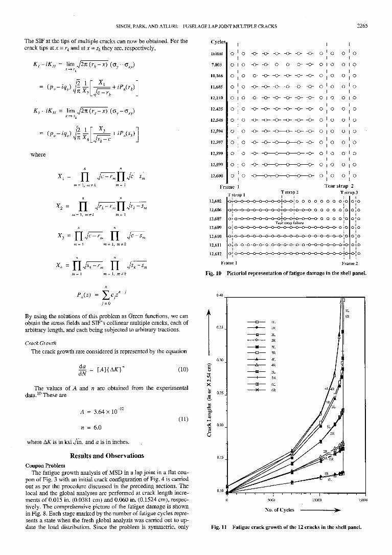
Fig. 10 Pictorial representation of fatigue damage in the shell panel.
P,(z) =
By using the solutions of this problem as Green functions, we canobtain the stress fields and SIF's collinear multiple cracks, each ofarbitrary length, and each being subjected to arbitrary tractions.
Crack GrowthThe crack growth rate considered is represented by the equation
(10)
The values of A and n are obtained from the experimentaldata.10 These are
(11)A = 3.64x10
n = 6.0
where AK is in ksi Jin. and a is in inches.
Results and ObservationsCoupon Problem
The fatigue growth analysis of MSD in a lap joint in a flat cou-pon of Fig. 3 with an initial crack configuration of Fig. 4 is carriedout as per the procedure discussed in the preceding sections. Thelocal and the global analyses are performed at crack length incre-ments of 0.015 in. (0.0381 cm) and 0.060 in. (0.1524 cm), respec-tively. The comprehensive picture of the fatigue damage is shownin Fig. 8. Each stage marked by the number of fatigue cycles repre-sents a state when the fresh global analysis was carried out to up-date the load distribution. Since the problem is symmetric, only
<sXO 0.25
JS
1
No. of Cycles
Fig. 11 Fatigue crack growth of the 12 cracks in the shell panel.

2266 SINGH, PARK, AND ATLURI: FUSELAGE LAP JOINT MULTIPLE CRACKS
Table 3 Crack lengths and the crack tip SIF at various stages of fatigue
MSD crack lengths,a in. or x 2.54 cm
Cycles 1 LInitial 0.1007,003 0.116
10,166 0.12311,685 0.12712,210 0.12912,435 0.12912,548 0.13012,594 0.13012,595 0.13012,597 0.13012,598 0.13012,599 0.13012,599 0.13012,600 0.130
1R0.1000.1160.1240.1280.1290.1300.1300.1310.1310.1310.1310.1310.131
2L0.1000.1320.1520.1650.1700.1730.1740.1750.1750.1750.1750.1750.175
2R 3L0.100 0.1000.133 0.1540.154 0.2030.167 0.2450.172 0.2640.175 0.2770.176 0.2850.177 0.2890.177 0.3060.177 0.3470.177 0.457
3R 4L0.110 .01100.159 0.1640.207 0.2220.249 0.2820.269 0.3420.286 0.4030.299 0.465
4R0.1000.1600.2200.2800.3380.3920.4420.4750.491
5L0.1000.1450.1780.2050.2160.2220.2250.2260.227
5R0.1000.1440.1780.2040.2140.2190.2220.2230.2230.2230.3170.479
Linkup
MSD crack tip SIF (ksi- Vm". or x 1 .Cycles 1 LInitial 9.3
7,003 9.310,166 9.411,685 9.512,210 9.512,435 9.612,548 9.612,594 10.112,595 10.212,597 10.812,598 11.012,599 11.212,599 11.612,600 78.8aL= left, R = right.
80 -t ——————
r1 60-
Li' 50-
c2^3 40-X
£,:'35
g 20-55•-s 1Q."5IM
0- — , — , — ,-
= —— =
0
1R9.49.49.59.59.69.79.7
10.310.310.911.210.210.6
—— Q — 1L—— * —— 1R
—— D — 2L—— $ —— 2R
—— • — 3L
—— ± — 4L—— A —— 4R
—— H — 5L
__ ffl _ 6L
—— X — 6R
A —
5000
No. of Cycles
2L10.611.211.711.912.112.212.311.911.611.710.871.480.4
^S'^^&L- — r^———— 6 —
10000
2R 3L10.6 11.811.3 13.411.7 14.612.0 14.912.2 16.112.3 16.512.4 17.011.5 40.811.1 43.111.0 55.811.2 59.6
3R 4L11.8 12.013.4 14.014.6 15.915.3 19.116.9 22.018.4 24.920.1 28.3
1 MPa- 44R12.114.015.919.021.623.826.240.642.7
5L11.412.513.213.613.814.214.614.515.1
5R11.312.513.213.413.413.413.312.912.754.559.573.5
Linkup
!!
1AAg|
Tahlp 4Id. UlC t
6L 6R0.100 0.1000.131 0.1310.148 0.1480.160 0.1590.164 0.1640.166 0.1660.168 0.1680.168 0.1680.168 0.1680.168 0.1680.168 0.1680.168 0.168
0.1680.168
6L 6R10.5 10.511.0 11.011.5 11.511.6 11.611.8 11.811.9 11.912.0 11.912.7 12.612.8 12.611.4 12.410.6 11.610.8 10.4
79.164.6
Frame and tear strap loads at various stages of fatigue
Frame and tear strap loads,
15000
->
CyclesInitial7,003
10,16611,68512,21012,43512,54812,59412,59512,59712,59812,59912,59912,60012,60612,60712,60912,61012,61112,612
Frame 110191019102010211021102110221028102910371040106710821110210621103185331434303490
Tear strap 131313132323232343436374650576126131031107111051121
Ib or x 4.45 N
Tear strap 2 Tear strap 326426426526526626626726926927828229132735731783474Fail
303030303030302929292827262554
-6016642810551609
Frame 21010101010101010101010101010101010101011101110111011101210801083163690^826813434
Fig. 12 Crack tip SIFs of the 12 cracks in the shell panel.
one-half of the domain is analyzed. In Fig. 8, the left-hand siderepresents the crack lengths and the right-hand side gives the cor-responding SIFs. The numbers within the ellipse denote the loca-tion and the magnitude of the maximum net ligament stress. Thevariations of SIF and the length of longest crack with number ofcycles is presented in Fig. 9. The crack growth rate increases sub-stantially at around 25,000 cycles. The first linkup occurs at33,925 cycles, and then the cracks snap through all of the other lig-aments almost instantaneously. This is both due to load redistri-bution as well as a substantial increase in crack tip SIF after thefirst linkup. The stress intensity factors increase with crack lengthand shoot up at linkup, thus increasing the crack growth rate toover 1/4 in./cycle. The load redistribution at first linkup shows thatthe next neighboring ligament has yielded. After the second
linkup, the dominant crack tip SIF is high enough to snap throughthe third ligament within two cycles. Now, at the linkup of allcracks, there exists a central crack of 5 in. (12.7 cm). If there areno cracks in the next outer ligaments, the cracks can be treated asbeing arrested. However, if there is even a small crack, it can growto the outermost hole in just a cycle, and then the outermost liga-ment yields, causing a complete failure of the panel. The signifi-cant observation is that the fatigue life of the coupon was only upto first linkup.
The load flow through the fasteners in the damaged row of fas-teners at various stages is given in Table 1. Table 2 gives the row-wise load distribution at all of the stages. Interestingly, after firstlinkup, the damaged row takes up more load. The explanation maybe as follows: As the cracks grow, the stiffness of the fastenerscomes down, and they shed the load to the intact ligament, whichnow carries more stress. But at linkup the ligament can no longer
SINGH, PARK, AND ATLURI: FUSELAGE LAP JOINT MULTIPLE CRACKS 2267
t
£i
3000 -
; 2000 -
>
Frame 1Frame 2
T strap 21 * * ? "
T strap 1 T strap 3
12590 12595 12600 12605 12610 12615No. of Cycles —————>-
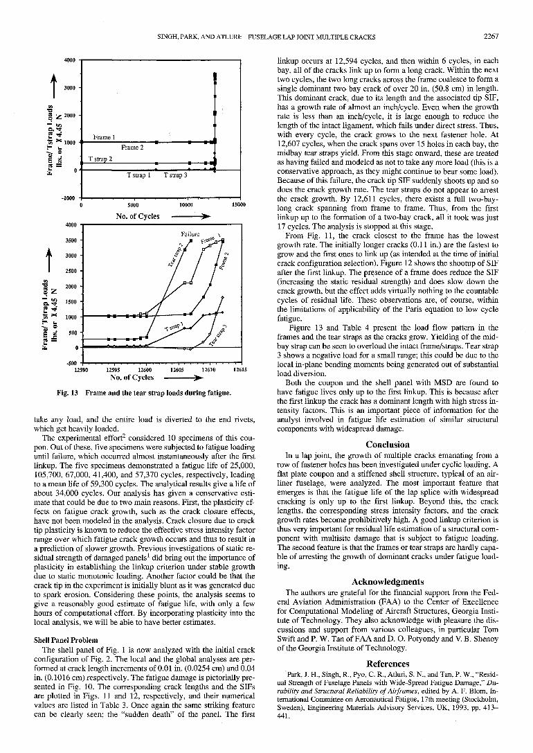
Fig. 13 Frame and the tear strap loads during fatigue.
take any load, and the entire load is diverted to the end rivets,which get heavily loaded.
The experimental effort2 considered 10 specimens of this cou-pon. Out of these, five specimens were subjected to fatigue loadinguntil failure, which occurred almost instantaneously after the firstlinkup. The five specimens demonstrated a fatigue life of 25,000,105,700, 67,000, 41,400, and 57,370 cycles, respectively, leadingto a mean life of 59,300 cycles. The analytical results give a life ofabout 34,000 cycles. Our analysis has given a conservative esti-mate that could be due to two main reasons. First, the plasticity ef-fects on fatigue crack growth, such as the crack closure effects,have not been modeled in the analysis. Crack closure due to cracktip plasticity is known to reduce the effective stress intensity factorrange over which fatigue crack growth occurs and thus to result ina prediction of slower growth. Previous investigations of static re-sidual strength of damaged panels1 did bring out the importance ofplasticity in establishing the linkup criterion under stable growthdue to static monotonic loading. Another factor could be that thecrack tip in the experiment is initially blunt as it was generated dueto spark erosion. Considering these points, the analysis seems togive a reasonably good estimate of fatigue life, with only a fewhours of computational effort. By incorporating plasticity into thelocal analysis, we will be able to have better estimates.
Shell Panel ProblemThe shell panel of Fig. 1 is now analyzed with the initial crack
configuration of Fig. 2. The local and the global analyses are per-formed at crack length increments of 0.01 in. (0.0254 cm) and 0.04in. (0.1016 cm) respectively. The fatigue damage is pictorially pre-sented in Fig. 10. The corresponding crack lengths and the SIFsare plotted in Figs. 11 and 12, respectively, and their numericalvalues are listed in Table 3. Once again the same striking featurecan be clearly seen; the "sudden death" of the panel. The first
linkup occurs at 12,594 cycles, and then within 6 cycles, in eachbay, all of the cracks link up to form a long crack. Within the nexttwo cycles, the two long cracks across the frame coalesce to form asingle dominant two-bay crack of over 20 in. (50.8 cm) in length.This dominant crack, due to its length and the associated tip SIF,has a growth rate of almost an inch/cycle. Even when the growthrate is less than an inch/cycle, it is large enough to reduce thelength of the intact ligament, which fails under direct stress. Thus,with every cycle, the crack grows to the next fastener hole. At12,607 cycles, when the crack spans over 15 holes in each bay, themidbay tear straps yield. From this stage onward, these are treatedas having failed and modeled as not to take any more load (this is aconservative approach, as they might continue to bear some load).Because of this failure, the crack tip SIF suddenly shoots up and sodoes the crack growth rate. The tear straps do not appear to arrestthe crack growth. By 12,611 cycles, there exists a full two-bay-long crack spanning from frame to frame. Thus, from the firstlinkup up to the formation of a two-bay crack, all it took was just17 cycles. The analysis is stopped at this stage.
From Fig. 11, the crack closest to the frame has the lowestgrowth rate. The initially longer cracks (0.11 in.) are the fastest togrow and the first ones to link up (as intended at the time of initialcrack configuration selection). Figure 12 shows the shootup of SIFafter the first linkup. The presence of a frame does reduce the SIF(increasing the static residual strength) and does slow down thecrack growth, but the effect adds virtually nothing to the countablecycles of residual life. These observations are, of course, withinthe limitations of applicability of the Paris equation to low cyclefatigue.
Figure 13 and Table 4 present the load flow pattern in theframes and the tear straps as the cracks grow. Yielding of the mid-bay strap can be seen to overload the intact frame/straps. Tear strap3 shows a negative load for a small range; this could be due to thelocal in-plane bending moments being generated out of substantialload diversion.
Both the coupon and the shell panel with MSD are found tohave fatigue lives only up to the first linkup. This is because afterthe first linkup the crack has a dominant length with high stress in-tensity factors. This is an important piece of information for theanalyst involved in fatigue life estimation of similar structuralcomponents with widespread damage.
ConclusionIn a lap joint, the growth of multiple cracks emanating from a
row of fastener holes has been investigated under cyclic loading. Aflat plate coupon and a stiffened shell structure, typical of an air-liner fuselage, were analyzed. The most important feature thatemerges is that the fatigue life of the lap splice with widespreadcracking is only up to the first linkup. Beyond this, the cracklengths, the corresponding stress intensity factors, and the crackgrowth rates become prohibitively high. A good linkup criterion isthus very important for residual life estimation of a structural com-ponent with multisite damage that is subject to fatigue loading.The second feature is that the frames or tear straps are hardly capa-ble of arresting the growth of dominant cracks under fatigue load-ing.
AcknowledgmentsThe authors are grateful for the financial support from the Fed-
eral Aviation Administration (FAA) to the Center of Excellencefor Computational Modeling of Aircraft Structures, Georgia Insti-tute of Technology. They also acknowledge with pleasure the dis-cussions and support from various colleagues, in particular TomSwift and P. W. Tan of FAA and D. O. Potyondy and V. B. Shenoyof the Georgia Institute of Technology.
References'Park, J. H., Singh, R., Pyo, C. R., Atluri, S. N., and Tan, P. W., "Resid-
ual Strength of Fuselage Panels with Wide-Spread Fatigue Damage," Du-rability and Structural Reliability of Airframes, edited by A. F. Blom, In-ternational Committee on Aeronautical Fatigue, 17th meeting (Stockholm,Sweden), Engineering Materials Advisory Services, UK, 1993, pp. 413-441.

2268 SINGH, PARK, AND ATLURI: FUSELAGE LAP JOINT MULTIPLE CRACKS
2Molent, L., and Jones, R., "Crack Growth and Repair of MultiSiteDamage of Fuselage Lap Joints," Engineering Fracture Mechanics, Vol.44, No. 4, 1993, pp. 627-637.
3Ashwell, D. G., and Sabir, A. B., "A New Cylindrical Shell Finite Ele-ment Based on Simple Independent Shape Functions," International Jour-nal of Mechanical Sciences, Vol. 14, No. 3, 1972, pp. 171-183.
4Swift, T., "Fracture Analysis of Stiffened Structures," American Soci-ety of Testing and Materials, STP 842, 1984, pp. 69-107.
5Park, J. H., and Atluri, S. N., "Fatigue Growth of Multiple Cracks neara Row of Fastener Holes in a Fuselage Lap Joint," Proceedings of the In-ternational Workshop on Structural Integrity of Aging Airplanes, edited byS. N. Atluri, P. Tong, and S. G. Sampath, Springer-Verlag, New York,1992, pp. 91-116; also Computational Mechanics, Vol. 13, No. 3, 1993,pp. 189-203.
6Park, J. H., Ogiso, T., and Atluri, S. N., "Analysis of Cracks in AgingAircraft Structures, With and Without Composite Patch Repairs," Compu-tational Mechanics, Vol. 10, No. 3/4, 1992, pp. 169-202.
7Swift, T., "Damage Tolerance in Pressurized Fuselages," llth Plant-ema Memorial Lecture, International Committee on Aeronautical Fatigue,14th meeting (Ottawa, Canada), 1987.
8Swift, T., "Residual Strength of Stiffened Structures," Lecture at Geor-gia Inst. of Technology, Atlanta, GA, Feb. 10, 1993.
9Muskhelishvili, N. I., Some Basic Problems of the Mathematical The-ory of Elasticity, Russian translation by J. R. M. Radok, Groningen,Noordhoff, 1953.
10Campbell, J. E., "Damage Tolerant Design Handbook," Metals andCeramics Information Center, Battelle Columbus Labs., Columbus, OH,Jan. 1975, pp. 8.1-10.
Recommended Reading from the AIAA Education Series
Boundarymuzz Layers
A.D. Young
1989,288 pp, illus, HardbackISBN 0-930403-57-6
AIAA Members $43.95Nonmembers $54.95
Order #: 57-6 (830)
Place your order today! Call 1 -800/682-AIAA
American Institute of Aeronautics and Astronautics
Publications Customer Service, 9 Jay Could Ct., P.O. Box 753, Waldorf, MD 20604FAX 301/843-0159 Phone 1 -800/682-2422 8 a.m. - 5 p.m. Eastern
"Excellent survey of basic methods." — I.S.Gartshore, University of British Columbia
A new and rare volume devoted to the topic ofboundary layers. Directed towards upper-levelundergraduates, postgraduates, young engineers,and researchers, the text emphasizes two-di-mensional boundary layers as a foundation ofthe subject, but includes discussion of three-dimensional boundary layers as well. Followingan introduction to the basic physical conceptsand the theoretical framework of boundary lay-ers, discussion includes: laminar boundary lay-ers; the physics of the transition from laminar toturbulent flow; the turbulent boundary layer andits governing equations in time-averaging form;drag prediction by integral methods; turbulencemodeling and differential methods; and currenttopics and problems in research and industry.
Sales Tax: CA residents, 8.25%; DC, 6%. For shipping and handling add $4.75 for 1 -4 books (callfor rates for higher quantities). Orders under $100.00 must be prepaid. Foreign orders must beprepaid and include a $20.00 postal surcharge. Please allow 4 weeks for delivery. Prices aresubject to change without notice. Returns will be accepted within 30 days. l\lon-U.S. residentsare responsible for payment of any taxes required by their government.