Group2 loca to test
46
LOCA Safety Analysis Review VARANS - Group 2 Truong Cong Thang (Group leader) Doan Quang Tuyen Nguyen Dinh Quen Do Trung Quan Nguyen Hoang Anh Dao Ngoc Phuong
Transcript of Group2 loca to test

LOCA Safety Analysis
ReviewVARANS - Group 2
Truong Cong Thang (Group leader)
Doan Quang Tuyen
Nguyen Dinh Quen
Do Trung Quan
Nguyen Hoang Anh
Dao Ngoc Phuong

5.1 Scope for Analysis
The initial conditions for the analysis of a postulated event shall be
specified to give the severest possible result with respect to the applied
criteria, taking into consideration the whole range of normal operation
and operating period of the nuclear reactor facility including long-term
physical change with burn-up in the core during various cycles and with
refueling and anticipated change in operational modes. The analysis
shall in general cover the time range up to the point where the event
terminates and it can be reasonably inferred that the reactor could
reach a cold shutdown state safely.
Review guide for safety evaluation

5.2 Assumptions on Safety Functions
(1) Of safety functions designed to address postulated events, those which are allowed to be taken
into account in the analysis, shall in general be limited to safety functions to be performed by
structures, systems and components belonging to MS-1 and MS-2 specified in the Review
Guide for Safety Importance Classification. Safety functions of structures, systems and
components belonging to MS-3 may be taken into account in the analysis only if taking
credit for these functions is proved to be justifiable.
(2) The analysis shall, in addition to a postulated event for the systems and components necessary to
deal with an accident, assume a single failure of a component that could give the severest
possible consequence for each of the fundamental safety functions such as reactor
shutdown, core cooling and radioactivity confinement. For a short-term period after
occurrence of an accident, a single failure on an active component shall be assumed, while
for a long-term period, a single failure on an active component or a passive component
shall be assumed. The failure may not generally be assumed on a component which is
operated before the occurrence of the event and will be operated after that. The failure of a
passive component may not be assumed, if a single failure is assumed and when the
system which includes the said component is designed to fulfill its required safety
functions, or when the failure can be removed or repaired within time so as not to impair
the safety, or when the probability of the failure is sufficiently low.
Review guide for safety evaluation
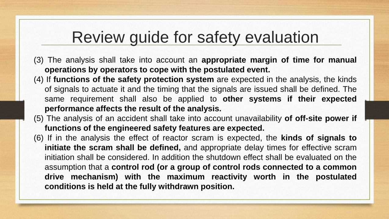
(3) The analysis shall take into account an appropriate margin of time for manual
operations by operators to cope with the postulated event.
(4) If functions of the safety protection system are expected in the analysis, the kinds
of signals to actuate it and the timing that the signals are issued shall be defined. The
same requirement shall also be applied to other systems if their expected
performance affects the result of the analysis.
(5) The analysis of an accident shall take into account unavailability of off-site power if
functions of the engineered safety features are expected.
(6) If in the analysis the effect of reactor scram is expected, the kinds of signals to
initiate the scram shall be defined, and appropriate delay times for effective scram
initiation shall be considered. In addition the shutdown effect shall be evaluated on the
assumption that a control rod (or a group of control rods connected to a common
drive mechanism) with the maximum reactivity worth in the postulated
conditions is held at the fully withdrawn position.
Review guide for safety evaluation

Categorization of eventSAR Appendix 10: 1.1.2.1 Definition:
“ Accidents" are abnormal states going beyond the abnormal operational transients described in Section 1.1.1, "Abnormal Operational Transients." Although they occur with a very low frequency , radioactive substances might possibly be released from the reactor installation should they occur. Therefore, they are events which must be postulated from the view point of evaluating the safety of the reactor installation.

Categorization of event
Accident includes following events:
(1) Loss of reactor coolant or significant change of reactor core cooling
a. Loss of reactor coolant (hereinafter called "LOCA")
b. Loss of reactor coolant flow
c. Seizure of reactor coolant pump

Acceptance CriteriaReview guide: 4.2
Acceptance criteria for accidents
(1) The core shall not be considerably damaged, and can be sufficiently cooled.
(2) Fuel enthalpy shall not exceed the specified limit.
(3) Pressure on the reactor coolant pressure boundary shall not exceed 120% of the maximum allowable working pressure.
(4) Pressure on the reactor containment boundary shall not exceed the maximum allowable working pressure.
(5) There is no significant risk of radiation exposure to the surrounding public.
Why has a acceptance criterion of MCPR for AOO, but not for
accident?

3.2.1.4 Review of conformance to acceptance criteria
a. A maximum calculation of a fuel clad temperature must be 12000C or less
b. A calculation of a stoichiometric oxidization quantity of fuel cladding must be 15% or less the thickness of the cladding before significant oxidation
c. The quantity of hydrogen that is generated in the core with the reaction between the fuel clad and structural members and water must be low enough to ensure the integrity of a containment vessel should be clearly identified
d. The design must enable long-term removal of decay heat even if variations in fuel geometry are consideredFuel enthalpy should be covered.
Number of damaged fuel rods should be given.
Acceptance Criteria

Computer codes
(2) Analytical methods
• The following three analytical codes described above in Section 1
,3 , "Calculation Codes Used in Analysis ," are to be used in the
analysis
a. LAMB: Analytical code for short-term thermohydraulic
transients
b , SCAT: Single-channel thermohydraulic analytical code
c. SAFER: Analytical code for long-term thermohydraulic
transients

Availability of safety systems
5.2 Assumptions on Safety Functions
Of safety functions designed to address postulated events, those which are allowed to be taken
into account in the analysis, shall in general be limited to safety functions to be performed by
structures, systems and components belonging to MS-1 and MS-2 specified in the Review
Guide for Safety Importance Classification. Safety functions of structures, systems and
components belonging to MS-3 may be taken into account in the analysis only if taking
credit for these functions is proved to be justifiable.
-> This requirement is compliedTable 1.2-1 Main safety functions considered for effect mitigating in analysis (1) and (2)
Classification Function Structure, System and/or
Components
MS-1 (ab.norm. transient and
accident)
Rapid shut down of reactor Control rods and Control rod driving
systems(Scram function)
Maintaining sub-criticality of core Control rods and Control rod driving
systems
Question: For “Maintaining sub-criticality of core” in the case of transient, Boron dilution could be used,
not only control rod.
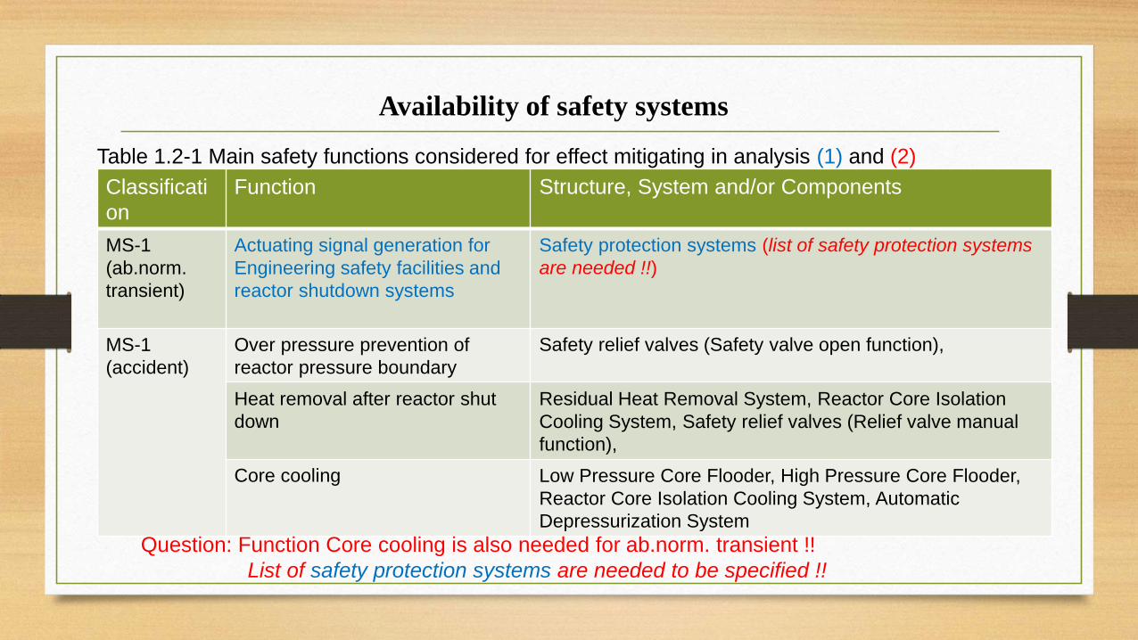
Classificati
on
Function Structure, System and/or Components
MS-1
(ab.norm.
transient)
Actuating signal generation for
Engineering safety facilities and
reactor shutdown systems
Safety protection systems (list of safety protection systems
are needed !!)
MS-1
(accident)
Over pressure prevention of
reactor pressure boundary
Safety relief valves (Safety valve open function),
Heat removal after reactor shut
down
Residual Heat Removal System, Reactor Core Isolation
Cooling System, Safety relief valves (Relief valve manual
function),
Core cooling Low Pressure Core Flooder, High Pressure Core Flooder,
Reactor Core Isolation Cooling System, Automatic
Depressurization System
Question: Function Core cooling is also needed for ab.norm. transient !!
List of safety protection systems are needed to be specified !!
Table 1.2-1 Main safety functions considered for effect mitigating in analysis (1) and (2)
Availability of safety systems

Classification Function Structure, System and/or
Components
MS-3 (ab.norm. transient) Mitigation of reactor pressure
increase
Safety relief valves (Relief valve
function), Turbine bypass valves
Restriction of reactor power
increase
Reactor coolant recirculation
system (Recirculation pump trip
function), Control rod withdrawal
monitoring system
Power maintaining of Reactor
coolant recirculation pumps
Recirculation pump MG sets
Question: How the Reactor coolant recirculation system can restrict
the increase of reactor power (depend on moderator coeff., Doppler
coef., etc.)?
Table 1.2-1 Main safety functions considered for effect mitigating in analysis (1)
and (2)
Availability of safety systems

Classification Function Structure, System and/or
Components
MS-3 (accident) Confirmation of abnormal
situation
Monitors of Heating,
Ventilating and Air
Conditioning systems
Question: Need the monitoring of pressure, flow??
Table 1.2-1 Main safety functions considered for effect mitigating in analysis (1)
and (2)
Availability of safety systems

3.2.1 Loss-of-coolant accidentsSAR KK6&7 (Appendix 10)
3.2.1.1 Causes
• Suppose the nearly inconceivable circumstance in which one of
the various pipes connected to the pressure vessel should break
during reactor operation for some reason. Should this occur, the
coolant will leak out of the pressure vessel or will be lost. In this
case, if the coolant cannot be replenished, it will become
impossible to cool the core sufficiently , and in the worst case
the fuel temperature will rise excessively on account of the decay
heat, and fission products may possibly be released from the fuel Satisfied
Boundary and Initial Conditions
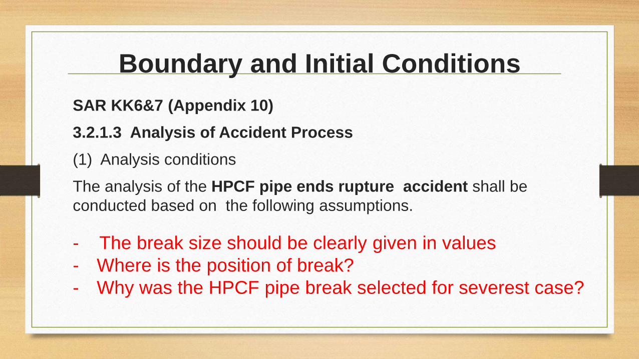
SAR KK6&7 (Appendix 10)
3.2.1.3 Analysis of Accident Process
(1) Analysis conditions
The analysis of the HPCF pipe ends rupture accident shall be
conducted based on the following assumptions.
- The break size should be clearly given in values
- Where is the position of break?
- Why was the HPCF pipe break selected for severest case?

Table 3.2, 1-1 Main calculating conditions for loss-of-coolant accidents
(SAR)Item Values used
Reactor thermal powerApproximately 102% of rated power (4,005 MWt)
Maximum linear heat generation rate 44.0 kW/m x 1.02
Core flow Rated flow 52.2 x 10³ t/h
Reactor dome pressure 73.1 kg/cm2 g
Core inlet enthalpy 294 kcal/kg
Flow rate, High-Pressure Core-Flooder System (rated value) 727 m3/h (per pump, at 7.0 kg/cm2 d)*
Flow rate, Low-Pressure Core-Flooder System (rated value) 954 m3/h (per pump, at 2.8 kg/cm2 d)*
Reactor Core Isolation Cooling 182 m3/h (per pump, at 82.8 - 10.5
System (rated value) kg/cm2 d)*
What are some others rated values?
Boundary and Initial Conditions

Boundary and Initial ConditionsSAR KK6&7 (Appendix 10)
a. The reactor shall operate at about 102% of rated power (4 ,005 MWt) and at a rated core flow rate immediately before the accident. An initial value of reactor pressure shall be 73.1 kg/cm2g. An initial value of MCPR will not actually become smaller than the operation limit (1.22) , but shall be 1.19 , or a value commonly used for an analysis of a loss-of-coolant accident in a boiling water reactor (BWR).
- Reactor power is conservative
- It should shown that the value used of initial pressure
is conservative by comparing with rated value.

Boundary and Initial ConditionsSAR KK6&7 (Appendix 10).
a. The maximum power density of a fuel rod that is used for the analysis
shall be 102% of 44.0 kW, or the operation limit. For a gap heat
transfer coefficient between a fuel clad and pellet, a value that will
make the analysis result more stringent shall be used in consideration of
variations in the heat transfer during a period of fuel burning
The heat transfer through fuel gap has not clearly identified?

Boundary and Initial Conditions
SAR KK6&7 (Appendix 10).
c. For the decay heat after the shutdown of the reactor, a value
determined from an equation (GE (mean) + 3σ) that incorporates a
safety margin into actual measurements, shall be used. For
reference, this equation incorporates a decay heat of actinide.
Satisfied

Boundary and Initial Conditions
SAR KK6&7 (Appendix 10).
d. Off-site power shall be lost concurrently with the occurrence of the accident Consequently, a recirculation pump will instantly be tripped. The reactor shall scram at a signal of a sharp drop in the core flow rate. Fig. 3.2.1-1 shows set values for the scrams at the sharp drop in the core flow rate
The description of SCRAM process was
mentioned
The time delay of scram was not specified in
value.
Review guide 5.2:
(6) If in the analysis the effect of reactor scram is expected, the kinds
of signals to initiate the scram shall be defined, and appropriate delay
times for effective scram initiation shall be considered.

Boundary and Initial Conditions

Boundary and Initial Conditions
e. It shall be considered that a signal for high pressure of a drywell
as a ECCS startup signal will be given earlier than a signal for a
low water level in the reactor (Level 2 or 1) , but ECCS is assumed
to conservatively start up at the signal for the low level
Conservative assumption of ECCS startup signal was used
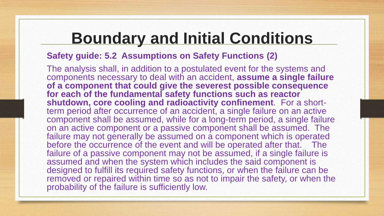
Boundary and Initial ConditionsSafety guide: 5.2 Assumptions on Safety Functions (2)
The analysis shall, in addition to a postulated event for the systems and components necessary to deal with an accident, assume a single failure of a component that could give the severest possible consequence for each of the fundamental safety functions such as reactor shutdown, core cooling and radioactivity confinement. For a short-term period after occurrence of an accident, a single failure on an active component shall be assumed, while for a long-term period, a single failure on an active component or a passive component shall be assumed. The failure may not generally be assumed on a component which is operated before the occurrence of the event and will be operated after that. The failure of a passive component may not be assumed, if a single failure is assumed and when the system which includes the said component is designed to fulfill its required safety functions, or when the failure can be removed or repaired within time so as not to impair the safety, or when the probability of the failure is sufficiently low.

Boundary and Initial Conditions
SAR KK6&7 (Appendix 10)
g. The most stringent single failure shall be assumed in the ECCS
network from the viewpoint of the capability of reactor cooling. The
most stringent single failure in the case of the HPCF pipe rupture
accident shall be a failure of a diesel generator that supplies power
to an integrity high-pressure core injection system
A diesel generator was assumed to be fail to
conform with single failure criterion

Boundary and Initial Conditions
SAR KK6&7 (Appendix 10)
h. The leakage of coolant from the fractured area shall be
calculated based on a uniform critical flow model
i. In a safety and relief valve, the relief valve works earlier than the
safety valve, but the safety valve shall be assumed to work earlier
Please explain the effects to safety when the safety valve is
assumed to work earlier than relief valve? (pressure boundary
was fail)

Boundary and Initial Conditions
SAR KK6&7 (Appendix 10).
j. In the calculation of a clad temperature , the following correlation equations are used to determine a heat transfer coefficient between the clad and the coolant
(1) Cooling of nucleate boiling: Correlation equation as a function of coolant void fraction
(2) Cooling of film boiling: Correlation equation that uses a correlation equation of spray flow cooling and the corrected Bromley Equation as a function of the void fraction
(3) Cooling of transition boiling: Correlation equation obtained after a heat transfer coefficient between nucleate and film boiling is interpolated with a degree of overheating of fuel cladding
(4) Steam cooling: Dittus-BoeIter Equation
(5) Spray flow cooling: Sun-Saha Equation
(6) Spray (falling water) cooling: Correlation equation based on actual measurements of SHTF test
(7) Wet cooling: A heat transfer coefficient after being wetted is based on the model of Andersen.
Boundary and Initial Conditions
There is no information about reactivity feedback
and fuel burn-up?

Evaluation of Results

Variations of core flow rate
SAR KK6&7 (Appendix 10)
The loss of offsite power
occurring simultaneously with
the accident , the core flow will
decrease rapidly because of
the shutdown of the
recirculation pumps.

Variations of reactor water level
SAR Appendix 10
The water level inside the core shroud
will start to drop after about 60
seconds. However , the Reactor Core
Isolation Cooling System will be
activated by low level (level 2) signals
of reactor water and start water
injection in about 59 seconds after the
accident. Why does the water level inside
the core keep high for 60s after
break occur?
Generally it should be dropped
rapidly.

Variations of core average pressureSAR KK6&7 (Appendix 10)
The Automatic Depressurization
Systems will also be activated by high
pressure signals of drywell and low
level (level 1) signals of reactor water
in about 176 seconds after the accident
to lower the reactor pressure , and two
Low-Pressure
Flooder Systems will begin to inject
water in about 364 seconds. The water
level inside the core shroud will not
drop below top of the active fuel and
the core will be kept f1 flooded.
Why does the reactor core can keep high pressure for
longtime (176s) after LOCA occurs?

Heat transfer coefficient change

Fuel cladding temperature change
- Figure 3.2.1-8 was not
provided!
- Figure 3.2.1-7 shows the
cladding temperature. The pick
cladding temperature is shown
as 6000C, not 5550C as
described in SAR!
SAR Appendix 10
Fig. 3.2.1-8 shows that the fuel
cladding-tube temperature is
about 5550C or less during a
complete break of the HPCF
lines.

Oxidation
SAR Appendix 10
There is very little increase in the thickness of the oxide layer on the
fuel cladding tubes because of the low temperature of the fuel
cladding tubes. Moreover, the zirconium-water reaction fraction in
all of the fuel cladding tubes is negligibly small
It should give a calculation results of the
total amount of hydrogen generated.

Other comments
- It should provide the time sequences (in table) that show
the operation of every system or component.
- The leakage flow depending time was not provided.
- There was not any description of operation action.
- There is not clear about the effect of single failure of
ECCS to the results.

- Cần bổ sung nhận xét về các mô hình phân tích ví dụ:
- Blowdown model
- Drywell model
- Vent-clearing model v.v…….
- (yêu cầu các mô hình này phải được dẫn chiếu đến tài
liệu thẩm định mô hình liên quan)

Câu hỏi liên quan tới Fukushima: có 3 lò bị nóng chảy vùng hoạt, tuy nhiên hydro lại từ 3 lò này qua hệ
thống thông gió sang lò thứ tư và dẫn tới nổ ở lò thứ 4, trong ABWR có thể xảy ra tình huống này ko?
Cách ngăn chặn ?
• Trong kết quả có nói về tăng giảm nhiệt độ vỏ thanh nhiên liệu mà
không có hình vẽ cần có hình vẽ thể hiện nhiệt độ vỏ thanh nhiên
liệu để làm rõ được sự thay đổi bề mặt vỏ thanh ?
Theo US-NRC -The calculated total amount of hydrogen generated from the chemical reaction of
the cladding with water or steam does not exceed 1% of the hypothetical amount that would be
generated if all of the metal in the cladding cylinders surrounding the fuel, excluding the cladding
surrounding the plenum volume, were to react. SAR: A rate of a zirconium-water reaction shall be 5 times larger than the result of loss-of-coolant analysis,
or shall be a rate obtained when the reaction is made in fuel dads with a thickness of 0.23 mil (equivalent
to 0.73% of the total quantity of fuel clads), but a higher result shall be used. In the analysis, the rate shall
be 0.73%.
-> conservative ?

3.5.1 Loss of Reactor coolant

G33. Systems for Controlling Containment Facility Atmosphere
(1) The containment facility atmosphere cleanup system shall be designedto be capable of reducing the concentration of radioactive materialsreleased to the environment in case of postulated events for reactorcontainment design.
(2) The flammable gas concentration control system shall be designed tobe capable of controlling the concentration of hydrogen or oxygen presentin the reactor containment in case of the postulated events for reactorcontainment design, thereby maintaining the integrity of the containmentfacility.
(3) The systems for controlling containment facility atmosphere shall bedesigned with redundancy or diversity and independence so that they canfulfill their safety functions even in case of unavailability of off-site power inaddition to an assumption of a single failure of any of the components thatcomprise the systems. They shall also be designed to allow testing withrespect to their functional capability.
Safety review guide

GUIDE_005
(1) An event is assumed that combustible gas is generated during a loss of the reactor coolant assumed in 3.4.1.
(2) The amount of hydrogen generated by metal-water reaction shall be the larger value of either five times the
amount generated by metal-water reaction that is calculated in 3.1.1 or the amount generated when the metal of
0.0058mm thickness from the surface of the cladding tubes of all fuel rods reacts with water.
(3) Assuming that 50% of halogen and 1% of the fission products excluding noble gas and halogen out of the
fission products inventory in the reactor core exist in the liquid phase of the water in the reactor containment, the
radiolytic decomposition of the water in the reactor containment shall be appropriately evaluated. Furthermore,
assuming that all other fission products excluding noble gas exist in the reactor core, the radiolytic decomposition
of the water in the reactor core shall be appropriately evaluated. The decomposition rate of the water per unit
energy absorbed shall be the value confirmed by experiments with an appropriate margin taken into account.
(4) For a design that adds materials such as alkali in the reactor containment water, the hydrogen generated by
chemical reaction with metal structures in the reactor containment shall be appropriately evaluated.
(5) For a design that provides a system to control the concentration of combustible gases, such as a hydrogen
recombiner, the function may be expected within the design range of these systems.
(6) As criteria, the concentration of either oxygen or hydrogen in the reactor containment atmosphere shall be 5%
or 4% or less, respectively, for at least 30 days after the occurrence of the event.
Safety review guide
Evaluation of Results

Variations of pressure in drywell and suppression
chamber• The figure is not clear,
the values can not be
identified!• The activating time of
ACCS was not shown
clearly.• The point that the
pressures drop suddenly
is the time of initiating
RHRs?• What are the effects
of single failure?

Variations of Temp. in Drywell and suppression
chamberThe assumption describers that:
It is assumed that the Residual Heat
Removal System will be manually switched
to the Containment-Vessel Spray-Cooling
System 10 minutes after the accident
But the Result shows:
The Residual Heat Removal System is
used at first as a Low-Pressure Flooder
System, but 15 minutes after accident it
is switched manually so that one pump will
be used as a Containment-Vessel Spray-
Cooling System to lower the pressure in the
containment vessel Do they conflict?

Results
• The temperature can drop suddenly?
Normally it will decrease slowly.
• The pick of temperatures and
pressures are lower than “limit
values”
But the acceptance criteria for
drywell and suppression chamber were
not listed!

3.5.2 Generation of Flammable Gases

Results