Group no 11
22
Gujarat Technological University Birla Vishvakarma Mahavidhyalay Electronics & Telecommunication Department Topic :- FSK, M-ary FSK, BPSK Modulation & Demodulation SUBMITED BY : - APAR TRIVEDI :130080112057 VATSAL BODIWALA :140083112002 GAURANG PRAPATI :140083112012 Under the Guidance Prof. D.C.Dalwadi ET Department, BVM.
-
Upload
birla-vishvakarma-mahavidyalay -
Category
Business
-
view
136 -
download
0
Transcript of Group no 11
Gujarat Technological University
Birla Vishvakarma Mahavidhyalay
Electronics & Telecommunication Department
Topic :- FSK, M-ary FSK, BPSK Modulation &
Demodulation
SUBMI T ED BY: -
APAR T RI VEDI : 130080112057
VAT SAL BO DI WALA : 140083112002
G AURANG PRAPAT I : 140083112012 Under the Guidance
Prof. D.C.Dalwadi
ET Department, BVM.

OUTLET :-
Introduction to FSK
Relationship between baud rate and bandwidth in FSK
FSK Example
BPSK Modulation & Demodulation
M-ary FSK
Frequency Shift Keying
Frequency of the carrier is varied to represent digital data (binary 0/1)
Peak amplitude and phase remain constant.
Avoid noise interference by looking at frequencies (change of a signal) and ignoring amplitudes.
Limitations of FSK is the physical capabilities of the carrier.
f1 and f2 equally offset by equal opposite amounts to the carrier freq.
In MFSK more than 2 freq are used, each signal element represents more than one bit

Fig of FSK :-
0)2cos(
1)2cos()(
2
1
binarytfA
binarytfAts

Relationship between baud rate and bandwidth in FSK
Relation cont…..
FSK shifts between two carrier frequencies
FSK spectrum = combination of two ASK spectra centered on fc1 and fc0.
BW = fc1-fc0 + Nbaud

FSK Examples (cont.)
1. What is the Find the minimum bandwidth for an FSK signal transmitting at 2000 bps. Transmission is in half-
duplex mode, and the carriers are separated by 3000 Hz.
• Because For FSK
BW = baud rate + fc1 - fc0
BW = bit rate + fc1 - fc0 = 2000 + 3000 = 5000 Hz
2. What is the maximum bit rates for an FSK signal if the bandwidth of the medium is 12,000 Hz and the
difference between the two carriers is 2000 Hz. Transmission is in full-duplex mode.
– Because the transmission is full duplex, only 6000 Hz is allocated for each direction.
– BW = baud rate + fc1 - fc0
– Baud rate = BW - (fc1 - fc0 ) = 6000 - 2000 = 4000
– But because the baud rate is the same as the bit rate, the bit rate is 4000 bps.

Binary phase-shift keying (BPSK)
BPSK (also sometimes called PRK, phase reversal keying, or 2PSK) is the simplest form of phase shift keying
(PSK). It uses two phases which are separated by 180° and so can also be termed 2-PSK. It does not
particularly matter exactly where the constellation points are positioned, and in this figure they are shown on
the real axis, at 0° and 180°. This modulation is the most robust of all the PSKs since it takes the highest level
of noise or distortion to make the demodulator reach an incorrect decision. It is, however, only able to
modulate at 1 bit/symbol (as seen in the figure) and so is unsuitable for high data-rate applications.
In the presence of an arbitrary phase-shift introduced by the communications channel, the demodulator is
unable to tell which constellation point is which. As a result, the data is often differentially encoded prior to
modulation.
BPSK is functionally equivalent to 2-QAM modulation.
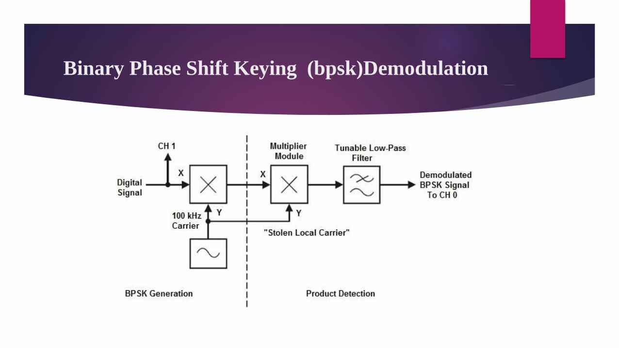
Binary Phase Shift Keying (bpsk)Demodulation

CONSTELLATION OF BPSK
BPSK (also sometimes called PRK, phase reversal keying, or 2PSK) is the simplest
form of phase shift keying (PSK). It uses two phases which are separated by 180° and
so can also be termed 2-PSK.
It does not particularly matter exactly where the constellation points are positioned,
and in this figure they are shown on the real axis, at 0° and 180°.
This modulation is the most robust of all the PSKs since it takes the highest level of
noise or distortion to make the demodulator reach an incorrect decision.

Binary Phase-Shift Keying
A binary phase-shift keying (BPSK) signal can be defined by
s(t) = A m(t) cos 2pfct, 0 < t< T (23.1)
where A is a constant, m(t) = +1 or -1, fc is the carrier frequency, and T is the bit
duration.
The signal has a power P = A2/2, so that A = 2P .
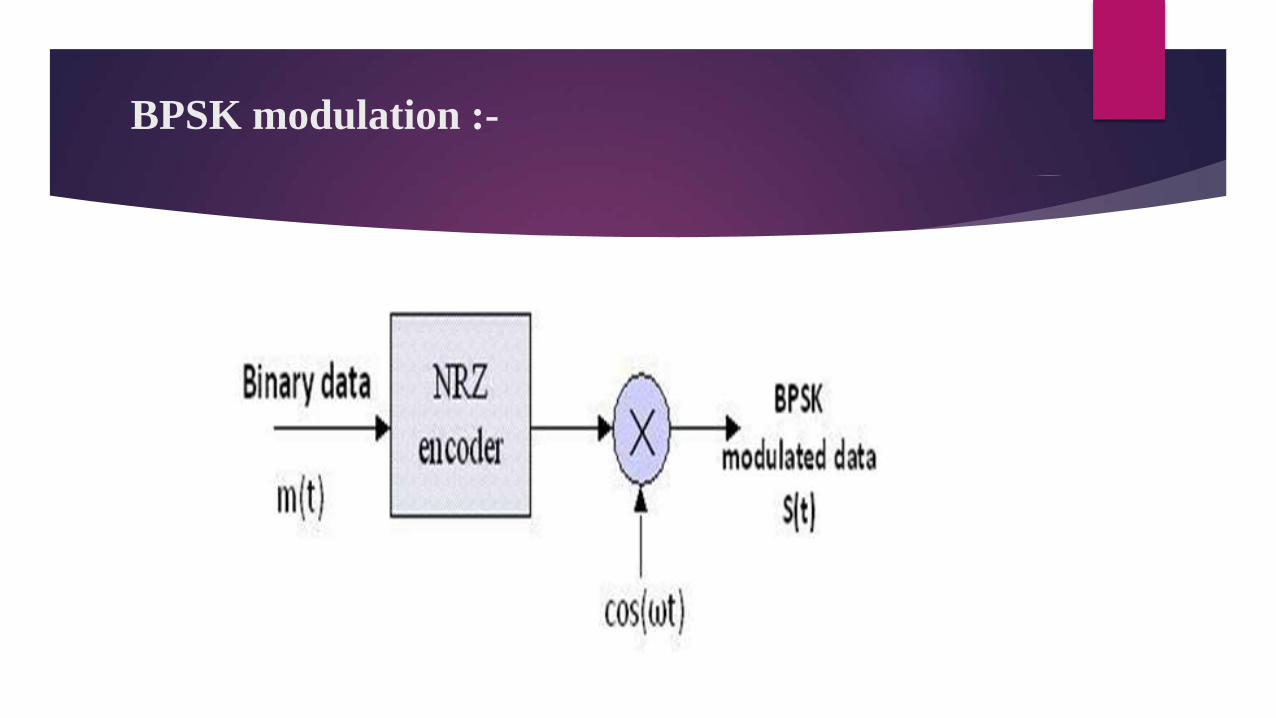
BPSK modulation :-

In digital modulation techniques a set of basis functions are chosen for a particular modulation
scheme. Generally the basis functions are orthogonal to each other. Once the basis function are
chosen, any vector in the signal space can be represented as a linear combination of the basis
functions.
In Binary Phase Shift Keying (BPSK) only one sinusoid is taken as basis function modulation.
Modulation is achieved by varying the phase of the basis function depending on the message
bits. The following equation outlines BPSK modulation technique.
A BPSK modulator can be implemented by NRZ coding the message bits (1 represented by +ve
voltage and 0 represented by -ve voltage) and multiplying the output by a reference oscillator
running at carrier frequency ω.
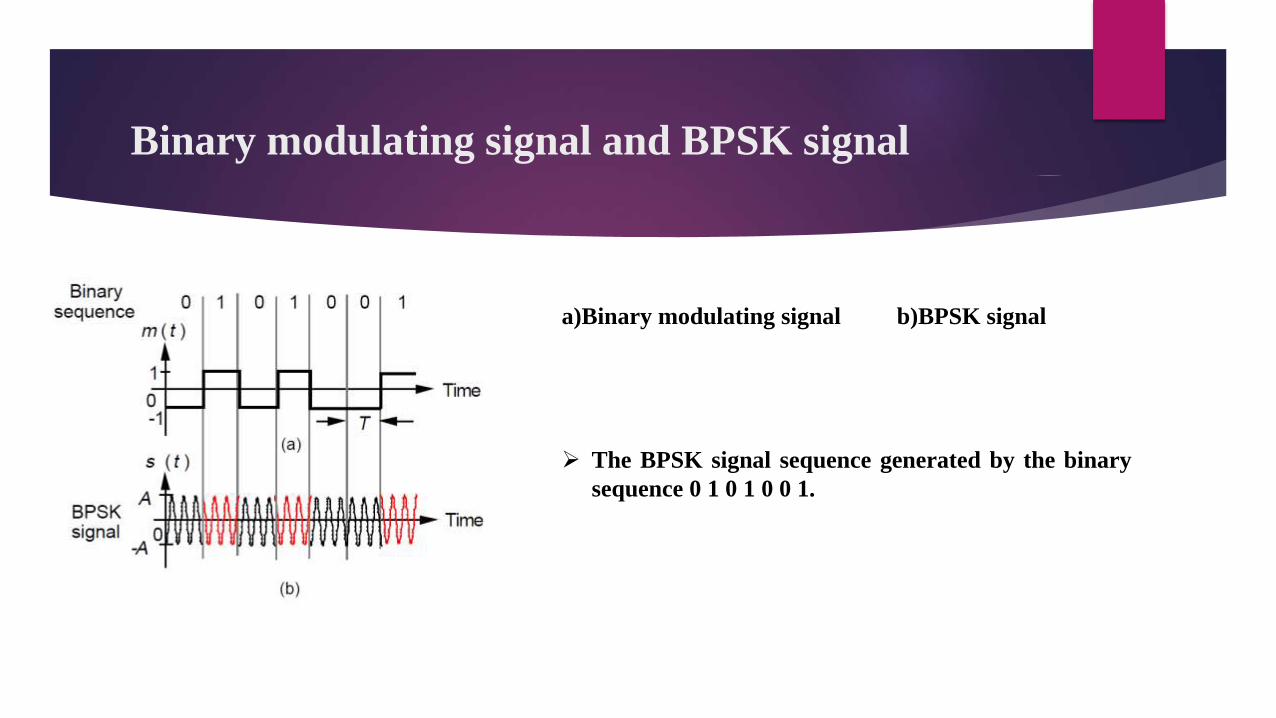
Binary modulating signal and BPSK signal
a)Binary modulating signal b)BPSK signal
The BPSK signal sequence generated by the binary
sequence 0 1 0 1 0 0 1.
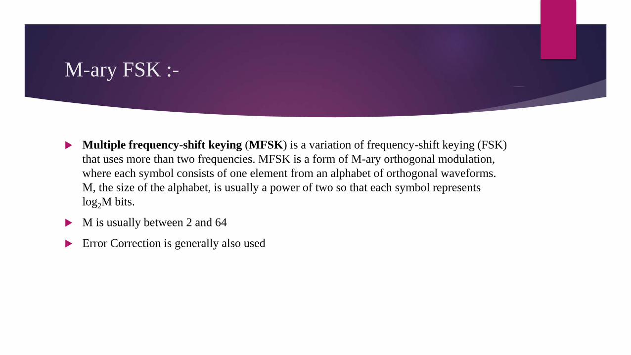
M-ary FSK :-
Multiple frequency-shift keying (MFSK) is a variation of frequency-shift keying (FSK)
that uses more than two frequencies. MFSK is a form of M-ary orthogonal modulation,
where each symbol consists of one element from an alphabet of orthogonal waveforms.
M, the size of the alphabet, is usually a power of two so that each symbol represents
log2M bits.
M is usually between 2 and 64
Error Correction is generally also used
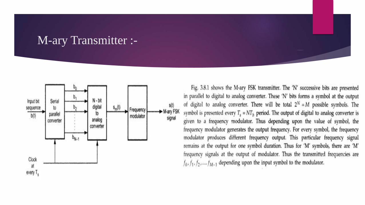
M-ary Transmitter :-
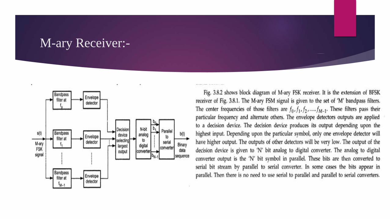
M-ary Receiver:-

Power Spectral Density & Bandwidth Of M-ary FSK :-

Bandwidth Of M-ary FSK :-

Geometrical represeantation of M-ary FSK :-
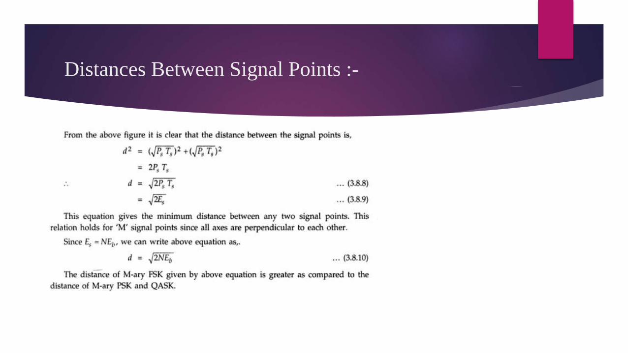
Distances Between Signal Points :-

THANK YOU