Group F: Cell Phone Forearm Holder
52
Washington University in St. Louis Washington University in St. Louis Washington University Open Scholarship Washington University Open Scholarship Mechanical Engineering Design Project Class Mechanical Engineering & Materials Science Fall 2016 Group F: Cell Phone Forearm Holder Group F: Cell Phone Forearm Holder Jacob Aley Washington University in St. Louis Emily Groth Washington University in St. Louis Sinclair Hodge Washington University in St. Louis Follow this and additional works at: https://openscholarship.wustl.edu/mems411 Part of the Mechanical Engineering Commons Recommended Citation Recommended Citation Aley, Jacob; Groth, Emily; and Hodge, Sinclair, "Group F: Cell Phone Forearm Holder" (2016). Mechanical Engineering Design Project Class. 47. https://openscholarship.wustl.edu/mems411/47 This Final Report is brought to you for free and open access by the Mechanical Engineering & Materials Science at Washington University Open Scholarship. It has been accepted for inclusion in Mechanical Engineering Design Project Class by an authorized administrator of Washington University Open Scholarship. For more information, please contact [email protected].
Transcript of Group F: Cell Phone Forearm Holder
Washington University in St. Louis Washington University in St. Louis
Washington University Open Scholarship Washington University Open Scholarship
Mechanical Engineering Design Project Class Mechanical Engineering & Materials Science
Fall 2016
Group F: Cell Phone Forearm Holder Group F: Cell Phone Forearm Holder
Jacob Aley Washington University in St. Louis
Emily Groth Washington University in St. Louis
Sinclair Hodge Washington University in St. Louis
Follow this and additional works at: https://openscholarship.wustl.edu/mems411
Part of the Mechanical Engineering Commons
Recommended Citation Recommended Citation Aley, Jacob; Groth, Emily; and Hodge, Sinclair, "Group F: Cell Phone Forearm Holder" (2016). Mechanical Engineering Design Project Class. 47. https://openscholarship.wustl.edu/mems411/47
This Final Report is brought to you for free and open access by the Mechanical Engineering & Materials Science at Washington University Open Scholarship. It has been accepted for inclusion in Mechanical Engineering Design Project Class by an authorized administrator of Washington University Open Scholarship. For more information, please contact [email protected].
MEMS 411
Senior
Design
Final Report
Cellphone Forearm
Holder
Emily Groth
Jacob Aley
Sinclair Hodge
The objective of this project was to design a cell phone holder, such that the phone can be used
on the go with one hand. We designed a holder that fits around the forearm. The phone attaches
to a helical track, so it can travel up and down the forearm, and stay at the top or bottom of the
track indefinitely.
MEMS 411 Final Report Cellphone Forearm Holder
Page 1 of 51
TABLE OF CONTENTS
List of Figures ........................................................................................................................................... 4
List of Tables ............................................................................................................................................ 5
1. Introduction ........................................................................................................................................... 6
1.1. Project problem statement ............................................................................................................. 6
1.2. List of team members .................................................................................................................... 6
2. Background Information Study – Concept of Operations ..................................................................... 6
2.1. A short design brief description that describes the problem ......................................................... 6
2.2. Summary of relevant background information ............................................................................. 6
2.2.1. Closest Competitors .................................................................................................................... 6
2.2.2. Significant Risk ........................................................................................................................... 8
2.2.3. Relevant Codes and Standards .................................................................................................... 8
3. Concept Design and Specification – Design requirements ................................................................... 9
3.1. Operational requirements allocated and decomposed to design requirements.............................. 9
3.1.1. Customer Interview Questions .............................................................................................. 9
3.1.2. List of identified operational and design requirements ....................................................... 10
3.1.3. Functional allocation and decomposition............................................................................ 11
3.2. Four concept drawings ................................................................................................................ 12
3.3. concept selection process ............................................................................................................ 15
3.3.1. Preliminary analysis of each concept’s physical feasibility based on design requirements,
function allocation, and functional decomposition ............................................................................. 15
3.3.2. Concept scoring................................................................................................................... 16
3.3.4. Final summary Statement .................................................................................................... 18
3.4. Proposed performance measures for the design .......................................................................... 18
3.5. Design constraints ....................................................................................................................... 18
3.5.1. Functional ........................................................................................................................... 18
3.5.2. Safety .................................................................................................................................. 18
3.5.3. Quality ................................................................................................................................. 18
3.5.4. Manufacturing ..................................................................................................................... 18
3.5.5. Timing ................................................................................................................................. 19
3.5.6. Economic ............................................................................................................................ 19
3.5.7. Ergonomic ........................................................................................................................... 19
3.5.8. Ecological ........................................................................................................................... 19
MEMS 411 Final Report Cellphone Forearm Holder
Page 2 of 51
3.5.9. Aesthetic ............................................................................................................................. 19
3.5.10. Life cycle ............................................................................................................................ 19
3.5.11. Legal ................................................................................................................................... 19
4. Embodiment and fabrication plan ....................................................................................................... 20
4.1. Embodiment drawing .................................................................................................................. 20
4.2. Parts List ..................................................................................................................................... 21
4.3. Draft detail drawings for each manufactured part ....................................................................... 22
4.4. Description of the design rationale for the choice/size/shape of each part ................................. 26
4.5. Gantt chart ................................................................................................................................... 26
5. Engineering analysis ........................................................................................................................... 26
5.1. Engineering Analysis PRoposal .................................................................................................. 26
5.2. Engineering analysis results ........................................................................................................ 26
5.2.1. Motivation ........................................................................................................................... 26
5.2.2. Summary statement of analysis done .................................................................................. 27
5.2.3. Methodology ....................................................................................................................... 29
5.2.4. Results ................................................................................................................................. 29
5.2.5. Significance ......................................................................................................................... 29
5.2.6. Summary of code and standards and their influence........................................................... 30
5.2.7. Motion Study Link .............................................................................................................. 30
5.3. Risk Assessment ......................................................................................................................... 30
5.3.1. Risk Identification ............................................................................................................... 30
5.3.2. Risk Impact or Consequence Assessment ........................................................................... 31
5.3.3. Risk Prioritization ............................................................................................................... 31
6. Working prototype .............................................................................................................................. 31
6.1. A preliminary demonstration of the working prototype ............................................................. 31
6.2. A final demonstration of the working prototype ......................................................................... 31
6.3. At least two digital photographs showing the prototype ............................................................. 31
6.4. A Short video clip link showing prototype performing .............................................................. 33
6.5. At least 4 additional digital photographs and their explanations ................................................ 34
7. Design documentation......................................................................................................................... 37
7.1. Final Drawings and Documentation ........................................................................................... 37
7.1.1. ENGINEERING DRAWINGS ........................................................................................... 37
7.1.2. Sourcing instructions........................................................................................................... 43
MEMS 411 Final Report Cellphone Forearm Holder
Page 3 of 51
7.2. Final Presentation ........................................................................................................................ 44
7.2.1. EXTERNAL REVIEW BOARD PRESENTATION ......................................................... 44
7.2.2. LINK TO EXTERNAL REVIEW BOARD PRESENTATION VIDEO ........................... 44
7.3. Teardown .................................................................................................................................... 45
8. Discussion ........................................................................................................................................... 46
8.1. Using the final prototype produced to obtain values for metrics, evaluate the quantified needs
equations for the design. How well were the needs met? Discuss the result. ....................................... 46
8.2. Discuss any significant parts sourcing issues? Did it make sense to scrounge parts? Did any
vendor have an unreasonably long part delivery time? What would be your recommendations for
future projects?........................................................................................................................................ 47
8.3. Discuss the overall experience: ................................................................................................... 48
8.3.1. Was the project more of less difficult than you had expected? ........................................... 48
8.3.2. Does your final project result align with the project description? ...................................... 48
8.3.3. Did your team function well as a group? ............................................................................ 48
8.3.4. Were your team member’s skills complementary? ............................................................. 48
8.3.5. Did your team share the workload equally? ........................................................................ 48
8.3.6. Was any needed skill missing from the group? .................................................................. 49
8.3.7. Did you have to consult with your customer during the process, or did you work to the
original design brief? .......................................................................................................................... 49
8.3.8. Did the design brief (as provided by the customer) seem to change during the process? ... 49
8.3.9. Has the project enhanced your design skills? ..................................................................... 49
8.3.10. Would you now feel more comfortable accepting a design project assignment at a job?... 49
8.3.11. Are there projects that you would attempt now that you would not attempt before? ......... 49
9. Appendix A - Parts List ...................................................................................................................... 50
10. Appendix B - Bill of Materials ................................................................................................... 50
11. Appendix C - CAD Models AND STRESS TEST REPORTS ................................................... 50
12. Annotated Bibliography .............................................................................................................. 50
MEMS 411 Final Report Cellphone Forearm Holder
Page 4 of 51
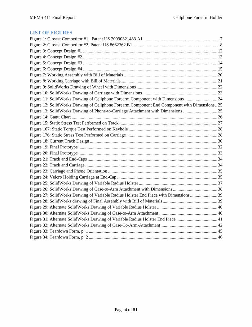
LIST OF FIGURES
Figure 1: Closest Competitor #1, Patent US 20090321483 A1 ................................................................... 7
Figure 2: Closest Competitor #2, Patent US 8662362 B1 ............................................................................ 8
Figure 3: Concept Design #1 ...................................................................................................................... 12
Figure 4: Concept Design #2 ...................................................................................................................... 13
Figure 5: Concept Design #3 ...................................................................................................................... 14
Figure 6: Concept Design #4 ...................................................................................................................... 15
Figure 7: Working Assembly with Bill of Materials .................................................................................. 20
Figure 8: Working Carriage with Bill of Materials ..................................................................................... 21
Figure 9: SolidWorks Drawing of Wheel with Dimensions ....................................................................... 22
Figure 10: SolidWorks Drawing of Carriage with Dimensions .................................................................. 23
Figure 11: SolidWorks Drawing of Cellphone Forearm Component with Dimensions ............................. 24
Figure 12: SolidWorks Drawing of Cellphone Forearm Component End Component with Dimensions .. 25
Figure 13: SolidWorks Drawing of Phone-to-Carriage Attachment with Dimensions .............................. 25
Figure 14: Gantt Chart ................................................................................................................................ 26
Figure 15: Static Stress Test Performed on Track ...................................................................................... 27
Figure 167: Static Torque Test Performed on Keyhole .............................................................................. 28
Figure 176: Static Stress Test Performed on Carriage ................................................................................ 28
Figure 18: Current Track Design ................................................................................................................ 30
Figure 19: Final Prototype .......................................................................................................................... 32
Figure 20: Final Prototype .......................................................................................................................... 33
Figure 21: Track and End-Caps .................................................................................................................. 34
Figure 22: Track and Carriage .................................................................................................................... 34
Figure 23: Carriage and Phone Orientation ................................................................................................ 35
Figure 24: Velcro Holding Carriage at End-Cap ........................................................................................ 35
Figure 25: SolidWorks Drawing of Variable Radius Holster ..................................................................... 37
Figure 26: SolidWorks Drawing of Case-to-Arm Attachment with Dimensions ....................................... 38
Figure 27: SolidWorks Drawing of Variable Radius Holster End Piece with Dimensions ........................ 39
Figure 28: SolidWorks drawing of Final Assembly with Bill of Materials ................................................ 39
Figure 29: Alternate SolidWorks Drawing of Variable Radius Holster ..................................................... 40
Figure 30: Alternate SolidWorks Drawing of Case-to-Arm Attachment ................................................... 40
Figure 31: Alternate SolidWorks Drawing of Variable Radius Holster End Piece .................................... 41
Figure 32: Alternate SolidWorks Drawing of Case-To-Arm-Attachment .................................................. 42
Figure 33: Teardown Form, p. 1 ................................................................................................................. 45
Figure 34: Teardown Form, p. 2 ................................................................................................................. 46
MEMS 411 Final Report Cellphone Forearm Holder
Page 5 of 51
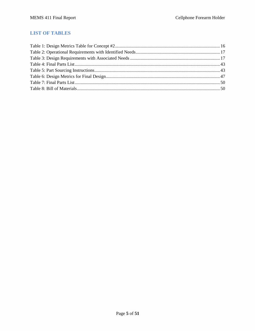
LIST OF TABLES
Table 1: Design Metrics Table for Concept #2 ........................................................................................... 16
Table 2: Operational Requirements with Identified Needs ......................................................................... 17
Table 3: Design Requirements with Associated Needs .............................................................................. 17
Table 4: Final Parts List .............................................................................................................................. 43
Table 5: Part Sourcing Instructions ............................................................................................................. 43
Table 6: Design Metrics for Final Design ................................................................................................... 47
Table 7: Final Parts List .............................................................................................................................. 50
Table 8: Bill of Materials ............................................................................................................................ 50
MEMS 411 Final Report Cellphone Forearm Holder
Page 6 of 51
1. INTRODUCTION
1.1. PROJECT PROBLEM STATEMENT
Design a forearm device that stores cell phones while traveling and provides an easy access ap-
paratus for one handed use on the go. A compression sleeve will be the main feature as it will be
the way in which our device will stay on the users arm. An adjustable apparatus that securely
holsters the cellphone will be another feature so that our device will be viable for cellphones of
varying dimensions. A swivel apparatus that will allow users to select horizontal or vertical
viewing of the cellphone while connected to our device. A track system that allows for the
movement of the cellphone from different positions on our device.
1.2. LIST OF TEAM MEMBERS
Emily Groth, Jacob Aley, Sinclair “Sin” Hodge
2. BACKGROUND INFORMATION STUDY – CONCEPT OF OPERATIONS
2.1. A SHORT DESIGN BRIEF DESCRIPTION THAT DESCRIBES THE PROBLEM
Cell phones are a continuously evolving technology and an integral part of modern life. Just
about everything can be done with cell phones. However, as technology changes and cell phones
evolve, there has always been one constant. Cell phones are always hand held. Our problem is to
design an integrated system that carries a cell phone on the forearm while traveling and provides
an easy access apparatus for cell phone use on the forearm.
2.2. SUMMARY OF RELEVANT BACKGROUND INFORMATION
2.2.1. Closest Competitors
Universal wrist-forearm docking station for mobile electronic devices:
The closest parallel to our design prompt was a universal wrist-forearm docking station and car-
rier for mobile electronic devices. The device offers adjustability both in regards to rotation of
the phone’s angle as well as the linear position in order to accommodate every individual’s pref-
erences. The entire device is then held onto the forearm by use of adjustable straps which are
used to provide both comfort and variability for the targeted consumer. By contrast, our project
was sleeker, stylish, and streamlined while accomplishing similar tasks while also providing a
secure method for protecting the cellphone.
MEMS 411 Final Report Cellphone Forearm Holder
Page 7 of 51
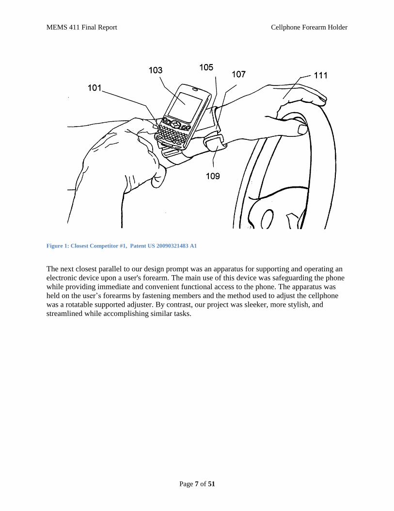
Figure 1: Closest Competitor #1, Patent US 20090321483 A1
The next closest parallel to our design prompt was an apparatus for supporting and operating an
electronic device upon a user's forearm. The main use of this device was safeguarding the phone
while providing immediate and convenient functional access to the phone. The apparatus was
held on the user’s forearms by fastening members and the method used to adjust the cellphone
was a rotatable supported adjuster. By contrast, our project was sleeker, more stylish, and
streamlined while accomplishing similar tasks.

MEMS 411 Final Report Cellphone Forearm Holder
Page 8 of 51
Figure 2: Closest Competitor #2, Patent US 8662362 B1
2.2.2. Significant Risk
There are multitudes of cell phone companies around the world. Due to this fact, there is no
standard for the size and shape of the device. There are only basic guidelines in which the com-
panies have to follow, such as the fact that people should be able to hold the phone in their hands
in order to use it. This provides the most significant risk to our design in the fact that our appa-
ratus must be able to accommodate varying dimensions of cellphones in order to be feasible. We
believe that this is the most significant risk because if the device can only accommodate one
brand of phone, or even one particular model, we are significantly limiting our market which
then would then limit our possible profits.
2.2.3. Relevant Codes and Standards
MIL-STD-810, Environmental Engineering Considerations and Laboratory Tests is a United
States Military Standard that emphasizes equipment’s ability to stand up to harsh environments,
and various conditions that it will experience throughout its service life. It establishes chamber
test methods that replicate the effects of environments on the equipment rather than imitating the
environments themselves. The MIL-STD-810 test series are approved for use by all departments
and agencies of the United States Department of Defense (DoD). Although prepared specifically
for military applications, the standard is often used for commercial products as well. The current
document revision (as of 2012) is MIL-STD-810G which was issued on October 31, 2008. The
standard's guidance and test methods are intended to: (i) Define environmental stress sequences,
durations, and levels of equipment life cycles; (ii) Be used to develop analysis and test criteria
tailored to the equipment and its environmental life cycle; (iii) Evaluate equipment's performance
MEMS 411 Final Report Cellphone Forearm Holder
Page 9 of 51
when exposed to a life cycle of environmental stresses; (iv) Identify deficiencies, shortcomings,
and defects in equipment design, materials, manufacturing processes, packaging techniques, and
maintenance methods; and (v) Demonstrate compliance with contractual requirements.
The MIL-STD-810 is relevant because companies that produce cellphone cases claim that their
products are “waterproof, shockproof, etc” when in reality companies do little to no testing due
to related expenses. In order to test to see if a product meets military standards, a company
would have to hire an independent party to perform the tests, create or rent facilities in which to
simulate the environments that the product can be tested in, and then also have plenty of products
in which to test. Since there is no commercial agency or organization that certifies compliance,
vendors, and manufacturers can technically create the test methods for their specific product's
application. Our product will be tested in normal operating conditions, which will include every-
day St. Louis weather.
3. CONCEPT DESIGN AND SPECIFICATION – DESIGN REQUIREMENTS
3.1. OPERATIONAL REQUIREMENTS ALLOCATED AND DECOMPOSED TO
DESIGN REQUIREMENTS
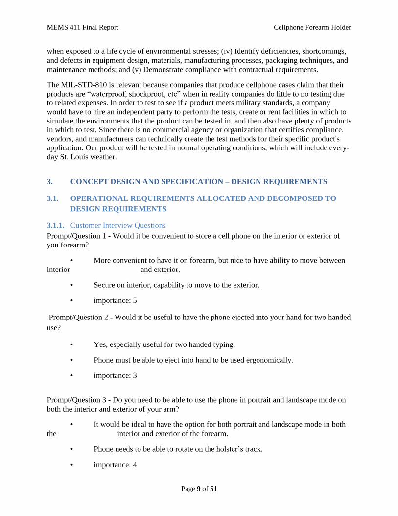
3.1.1. Customer Interview Questions
Prompt/Question 1 - Would it be convenient to store a cell phone on the interior or exterior of
you forearm?
• More convenient to have it on forearm, but nice to have ability to move between
interior and exterior.
• Secure on interior, capability to move to the exterior.
• importance: 5
Prompt/Question 2 - Would it be useful to have the phone ejected into your hand for two handed
use?
• Yes, especially useful for two handed typing.
• Phone must be able to eject into hand to be used ergonomically.
• importance: 3
Prompt/Question 3 - Do you need to be able to use the phone in portrait and landscape mode on
both the interior and exterior of your arm?
• It would be ideal to have the option for both portrait and landscape mode in both
the interior and exterior of the forearm.
• Phone needs to be able to rotate on the holster’s track.
• importance: 4

MEMS 411 Final Report Cellphone Forearm Holder
Page 10 of 51
3.1.2. List of identified operational and design requirements
Operational Requirements:
Phone Holster with movable case
1. Phone Case
• Female clip compatible with carriage
• Slim/sleek design to not get caught on clothes
• Protects phone from elements
2. Holster Track
• Sleek and discrete
• Carriage doesn’t fall out of track
• Shape of cross-section matches with carriage
• Wraps around holster
• Has stops on interior and exterior of forearm
3. Holster Carriage
• Moves smoothly through track
• Compatible with phone case
• Able to move around corners
4. Extending Arm
• Stores inside the “sleeve” of the wrist holder
• Extends out to a ball joint for ease of two-handed use
5. Operating Environment
• Number of user-controlled action
• Number of moving parts
• Case and holster protect phone
MEMS 411 Final Report Cellphone Forearm Holder
Page 11 of 51
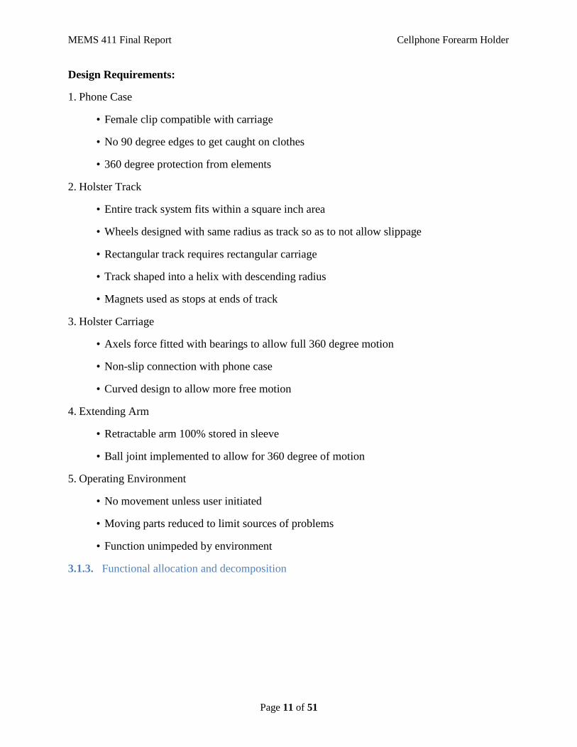
Design Requirements:
1. Phone Case
• Female clip compatible with carriage
• No 90 degree edges to get caught on clothes
• 360 degree protection from elements
2. Holster Track
• Entire track system fits within a square inch area
• Wheels designed with same radius as track so as to not allow slippage
• Rectangular track requires rectangular carriage
• Track shaped into a helix with descending radius
• Magnets used as stops at ends of track
3. Holster Carriage
• Axels force fitted with bearings to allow full 360 degree motion
• Non-slip connection with phone case
• Curved design to allow more free motion
4. Extending Arm
• Retractable arm 100% stored in sleeve
• Ball joint implemented to allow for 360 degree of motion
5. Operating Environment
• No movement unless user initiated
• Moving parts reduced to limit sources of problems
• Function unimpeded by environment
3.1.3. Functional allocation and decomposition

MEMS 411 Final Report Cellphone Forearm Holder
Page 12 of 51
3.2. FOUR CONCEPT DRAWINGS
Figure 3: Concept Design #1
MEMS 411 Final Report Cellphone Forearm Holder
Page 13 of 51
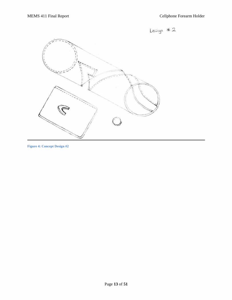
Figure 4: Concept Design #2
MEMS 411 Final Report Cellphone Forearm Holder
Page 14 of 51
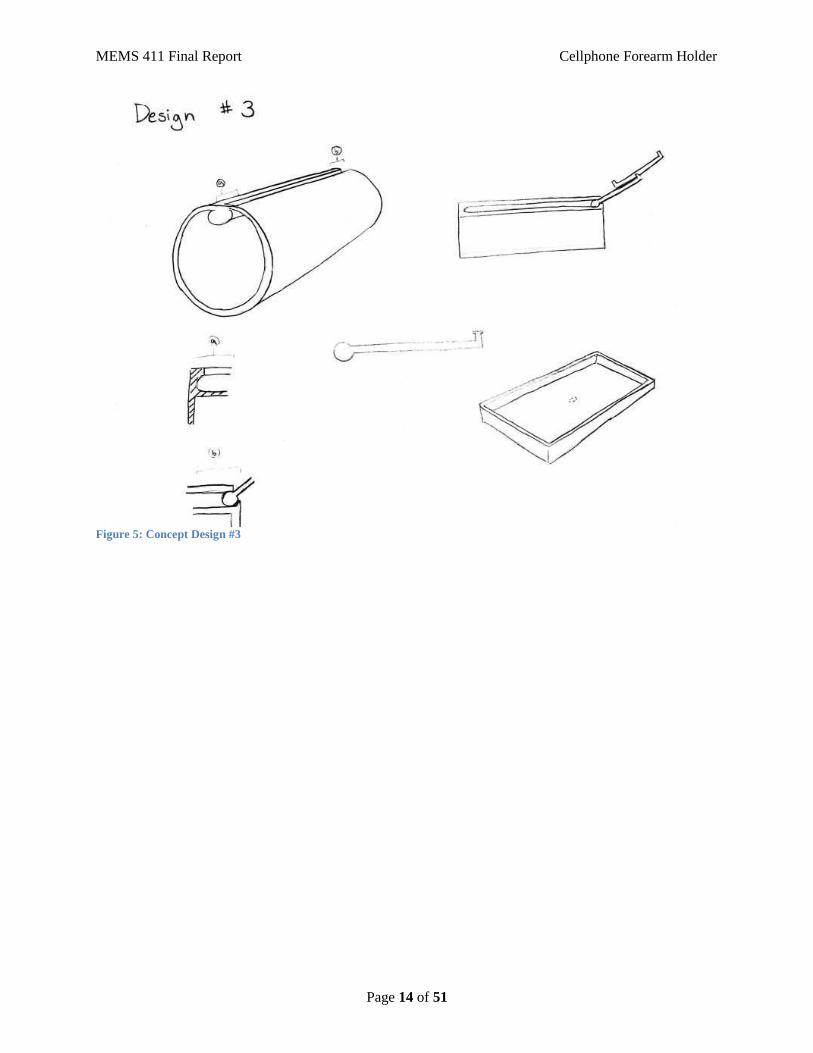
Figure 5: Concept Design #3

MEMS 411 Final Report Cellphone Forearm Holder
Page 15 of 51
Figure 6: Concept Design #4
3.3. CONCEPT SELECTION PROCESS
3.3.1. Preliminary analysis of each concept’s physical feasibility based on design requirements,
function allocation, and functional decomposition
Concept 1:
This concept allows for movement of the phone up and down the arm as well as rotation
of the phone between portrait and landscape mode as well as a few other options in be-
tween. This design allows for the storage of the phone on the inside and outside of the
arm near the wrist, and the phone slides into the track near the elbow.
Concept 2:
This concept allows for storage of phone at one end and a quick release of the phone
from the apparatus at the other end. It has the same phone rotation mechanic as Concept
1, and the phone slides into the track near the elbow. The phone rests in the hook of the
track near the wrist. The helical shape of the track allows for a one armed motion to get
phone from storage to be released.
MEMS 411 Final Report Cellphone Forearm Holder
Page 16 of 51
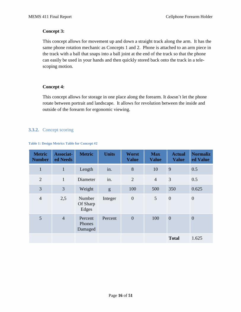
Concept 3:
This concept allows for movement up and down a straight track along the arm. It has the
same phone rotation mechanic as Concepts 1 and 2. Phone is attached to an arm piece in
the track with a ball that snaps into a ball joint at the end of the track so that the phone
can easily be used in your hands and then quickly stored back onto the track in a tele-
scoping motion.
Concept 4:
This concept allows for storage in one place along the forearm. It doesn’t let the phone
rotate between portrait and landscape. It allows for revolution between the inside and
outside of the forearm for ergonomic viewing.
3.3.2. Concept scoring
Table 1: Design Metrics Table for Concept #2
Metric
Number
Associat-
ed Needs
Metric Units Worst
Value
Max
Value
Actual
Value
Normaliz
ed Value
1 1 Length in. 8 10 9 0.5
2 1 Diameter in. 2 4 3 0.5
3 3 Weight g 100 500 350 0.625
4 2,5 Number
Of Sharp
Edges
Integer 0 5 0 0
5 4 Percent
Phones
Damaged
Percent 0 100 0 0
Total 1.625
MEMS 411 Final Report Cellphone Forearm Holder
Page 17 of 51
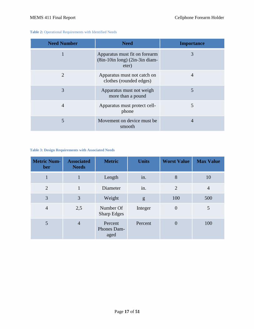
Table 2: Operational Requirements with Identified Needs
Need Number Need Importance
1 Apparatus must fit on forearm
(8in-10in long) (2in-3in diam-
eter)
3
2 Apparatus must not catch on
clothes (rounded edges)
4
3 Apparatus must not weigh
more than a pound
5
4 Apparatus must protect cell-
phone
5
5 Movement on device must be
smooth
4
Table 3: Design Requirements with Associated Needs
Metric Num-
ber
Associated
Needs
Metric Units Worst Value Max Value
1 1 Length in. 8 10
2 1 Diameter in. 2 4
3 3 Weight g 100 500
4 2,5 Number Of
Sharp Edges
Integer 0 5
5 4 Percent
Phones Dam-
aged
Percent 0 100
MEMS 411 Final Report Cellphone Forearm Holder
Page 18 of 51
3.3.4. Final summary Statement
WINNER: Concept 2:
Concept 2 had several advantages over the other concepts. We think that the possibility for us-
ing just one arm to transport the phone between storage and the release is one of the more im-
portant ideals of this project and that the helical design is the best way to accomplish that
task. This design also allows for the rotation of the phone between portrait and landscape modes
which is another of our main goals for this project and this helical design concept allows for this
type of motion as well or better than the other concepts.
We eliminated Concept 4 because of the lack of movement up and down the forearm and the
lack of rotation that it offered. We eliminated Concept 3 because of the complexity of the arm
and ball joint and because we thought the arm would be a bit cumbersome or get in the way
when trying to use the phone in your hands. We eliminated Concept 1 even though it was our
initial design because it required two hands to use and we wanted to try to make this project as
easy to use as possible.
3.4. PROPOSED PERFORMANCE MEASURES FOR THE DESIGN
1) Carriage remains on track.
2) Phone and carriage can be held at either end of the track indefinitely.
3) Phone can be oriented in multiple ways on the carriage.
3.5. DESIGN CONSTRAINTS
3.5.1. Functional
Small enough to be worn on a forearm, and must be able to hold the phone at ei-
ther end of the track, allow for orientation rotation.
3.5.2. Safety
Must be made of a safe material to use on human skin, must not have any sharp
edges.
3.5.3. Quality
Must be fairly durable so it does not break when dropped.
3.5.4. Manufacturing
For prototype, limited volume to print in: printers are 6x6x6in so all parts have to
be within those dimensions.

MEMS 411 Final Report Cellphone Forearm Holder
Page 19 of 51
3.5.5. Timing
Printing parts can take hours per part, and there are multiple groups that need to
print parts. .
3.5.6. Economic
We needed to minimize the amount of plastics used, and also stay within our
budget of $331.20.
3.5.7. Ergonomic
The track must fit comfortably on the forearm, and therefore the helix must have a
radius that varies with the forearm.
3.5.8. Ecological
We must not print or throw away parts in excess, only print what we need, and
then use it.
3.5.9. Aesthetic
The apparatus needs to look clean and neat, and interesting enough so that people
will notice it and want to wear it.
3.5.10. Life cycle
The product must be modular, so that as parts break or need replacing consumers
can either print their own parts or pay to have parts printed for them.
3.5.11. Legal
In order to market this product as living up to the 810G standard we need to per-
form further testing at appropriate facilities.

MEMS 411 Final Report Cellphone Forearm Holder
Page 20 of 51
4. EMBODIMENT AND FABRICATION PLAN
4.1. EMBODIMENT DRAWING
Figure 7: Working Assembly with Bill of Materials

MEMS 411 Final Report Cellphone Forearm Holder
Page 21 of 51
Figure 8: Working Carriage with Bill of Materials
4.2. PARTS LIST
• Cellphone Forearm Component
• Cellphone Forearm End Component
• Phone-to-Carriage Attachment
• Carriage
• Wheel

MEMS 411 Final Report Cellphone Forearm Holder
Page 22 of 51
4.3. DRAFT DETAIL DRAWINGS FOR EACH MANUFACTURED PART
Figure 9: SolidWorks Drawing of Wheel with Dimensions

MEMS 411 Final Report Cellphone Forearm Holder
Page 23 of 51
Figure 10: SolidWorks Drawing of Carriage with Dimensions
MEMS 411 Final Report Cellphone Forearm Holder
Page 24 of 51
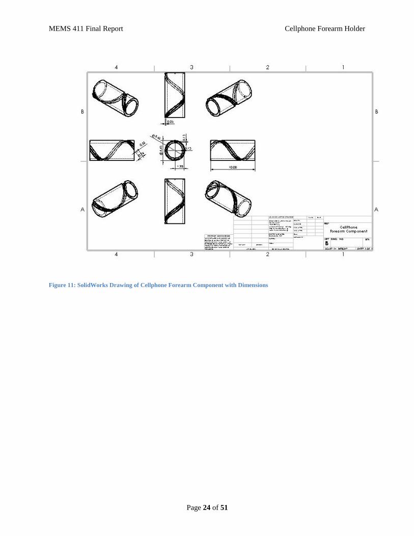
Figure 11: SolidWorks Drawing of Cellphone Forearm Component with Dimensions

MEMS 411 Final Report Cellphone Forearm Holder
Page 25 of 51
Figure 12: SolidWorks Drawing of Cellphone Forearm Component End Component with Dimensions
Figure 13: SolidWorks Drawing of Phone-to-Carriage Attachment with Dimensions
MEMS 411 Final Report Cellphone Forearm Holder
Page 26 of 51
4.4. DESCRIPTION OF THE DESIGN RATIONALE FOR THE
CHOICE/SIZE/SHAPE OF EACH PART
The carriage must be compatible with the phone case, and with the track, which is em-
bedded in the holster. Furthermore, the carriage must be able to move along the track, which
curves around the cylindrical holster. Therefore, the carriage must have a two rotational degree
of freedom along the track. It was decided that the best way to achieve this was to have a trough
embedded in the cylinder, with a single rail on the bottom. The carriage has two pairs of wheels
on the bottom of the carriage: a front and back pair. All the axes of rotation are perpendicular to
the carriage. The track runs through each pair of wheels independently, each wheel in both pairs
rotate in opposite directions. Because none of the parts will undergo heavy stress, they will all be
made out of ABS printed plastic.
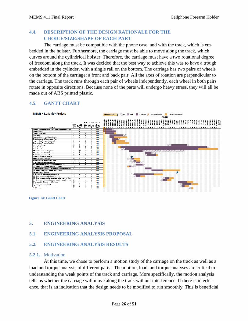
4.5. GANTT CHART
5. ENGINEERING ANALYSIS
5.1. ENGINEERING ANALYSIS PROPOSAL
5.2. ENGINEERING ANALYSIS RESULTS
5.2.1. Motivation
At this time, we chose to perform a motion study of the carriage on the track as well as a
load and torque analysis of different parts. The motion, load, and torque analyses are critical to
understanding the weak points of the track and carriage. More specifically, the motion analysis
tells us whether the carriage will move along the track without interference. If there is interfer-
ence, that is an indication that the design needs to be modified to run smoothly. This is beneficial
Figure 14: Gantt Chart
MEMS 411 Final Report Cellphone Forearm Holder
Page 27 of 51
to the study at this time because we could model several variations of carriages and test them
through the motion simulation rather than waste resources by experimenting with multiple print-
ed parts. The load and torque analyses give an indication of how much force the parts can with-
stand without warping or breaking. More specifically, the analyses will indicate if there are weak
points in our design. If that is the case, then the design would need to be altered to strengthen
them. This is beneficial to the study at this time because we can test alterations of parts before
printing them, which doesn't waste time or materials.
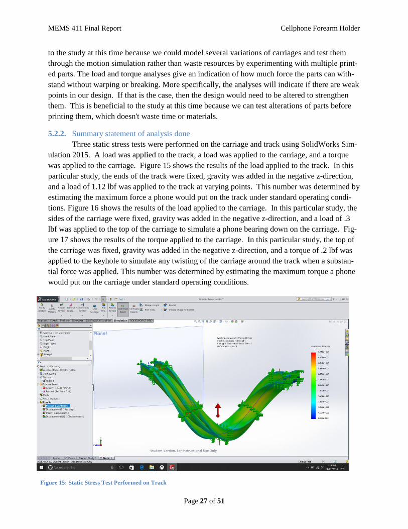
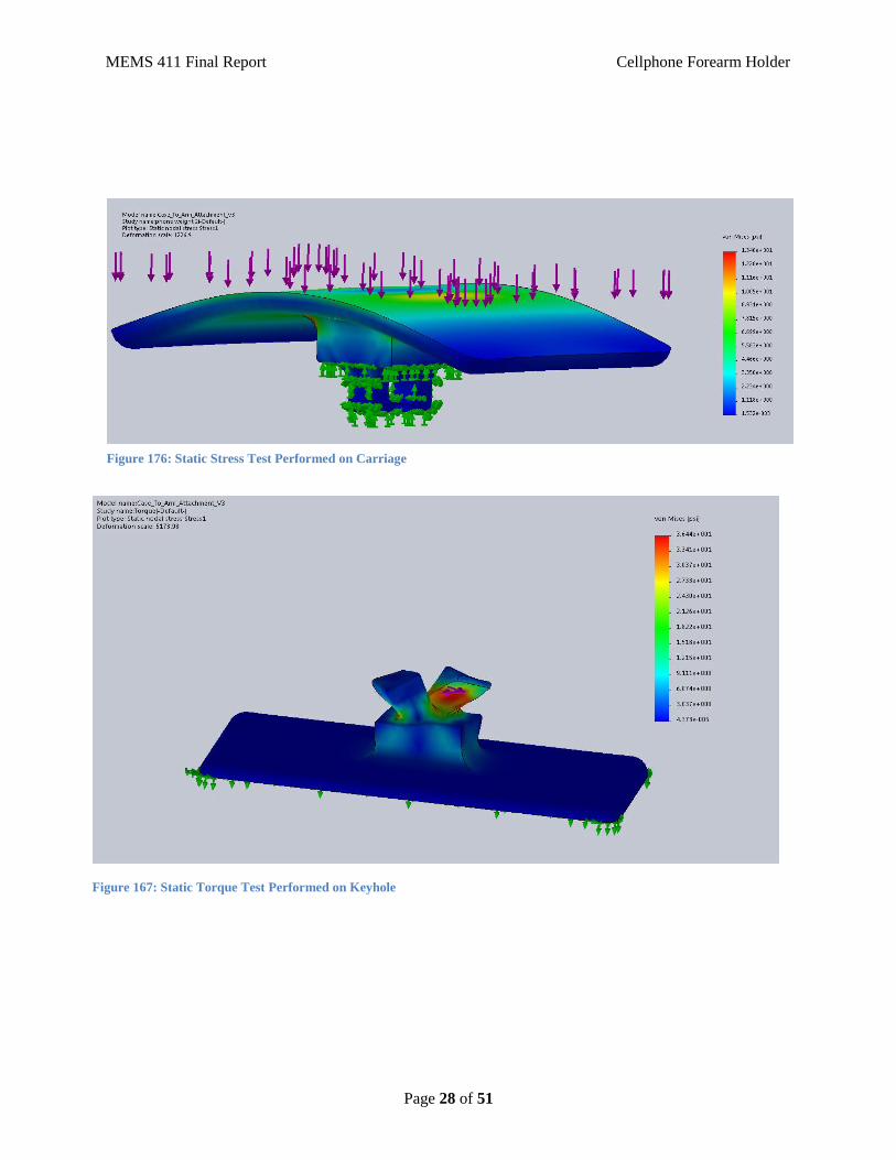
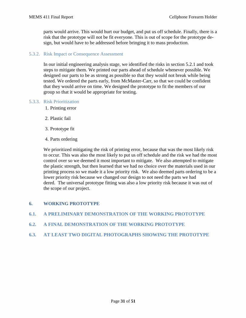
5.2.2. Summary statement of analysis done
Three static stress tests were performed on the carriage and track using SolidWorks Sim-
ulation 2015. A load was applied to the track, a load was applied to the carriage, and a torque
was applied to the carriage. Figure 15 shows the results of the load applied to the track. In this
particular study, the ends of the track were fixed, gravity was added in the negative z-direction,
and a load of 1.12 lbf was applied to the track at varying points. This number was determined by
estimating the maximum force a phone would put on the track under standard operating condi-
tions. Figure 16 shows the results of the load applied to the carriage. In this particular study, the
sides of the carriage were fixed, gravity was added in the negative z-direction, and a load of .3
lbf was applied to the top of the carriage to simulate a phone bearing down on the carriage. Fig-
ure 17 shows the results of the torque applied to the carriage. In this particular study, the top of
the carriage was fixed, gravity was added in the negative z-direction, and a torque of .2 lbf was
applied to the keyhole to simulate any twisting of the carriage around the track when a substan-
tial force was applied. This number was determined by estimating the maximum torque a phone
would put on the carriage under standard operating conditions.
Figure 15: Static Stress Test Performed on Track
MEMS 411 Final Report Cellphone Forearm Holder
Page 28 of 51
Figure 176: Static Stress Test Performed on Carriage
Figure 167: Static Torque Test Performed on Keyhole

MEMS 411 Final Report Cellphone Forearm Holder
Page 29 of 51
5.2.3. Methodology
As previously stated, a motion study and three static stress tests were performed on the
components of our device using the Motion Analysis and Simulation add-ons within SolidWorks
2015. The full results of these studies can be seen in Appendix D. The motion study was done
by creating an assembly of the track, the carriage, and two end pieces. In order to get the motion
study to work we had to copy the sketch of the end of the track and paste it onto both the front
and back sides of the keyhole on the carriage. Then from there we were able to use opposing
points on the corners of where the rail meets the support in the front and back sketches to create
a path mate with the track so that there was constant contact between the carriage and the track.
Then we added a tangent mate to the inside of the keyhole and the outside of the track’s rail.
This allowed us to accurately portray the physical interactions between the track and carriage.
Then by applying gravity to the carriage we were able to simulate the carriage moving around
the track. SolidWorks Simulations was used to perform the analyses for the three static stress
tests. Before beginning the study each part was designated to be ABS plastic so that SolidWorks
could accurately calculate the results of the stress tests. Then the forces were applied to simulate
real world use. Experimentation for all the studies was only required when it came to applying
forces to our models and creating mates between pieces in the assembly. Since all the simulation
was done in SolidWorks, no test rig was required.
5.2.4. Results
The results of our analysis are as follows. The motion study was inconclusive due to the
limitations of the SolidWorks software. Of the provided mate types in SolidWorks, the majority
of them are restricted to be used on flat planes, points, or simple curves. Our device has a helix
curve with a varying radius, and the design of the carriage is supposed to limit contact between
the keyhole and track. It is therefore impossible to properly simulate the carriage moving around
the track. However, as the working prototype demo proved, our current design of the carriage,
which has one keyhole, effectively travels along the track with minimal force needed to over-
come friction. The three static tests indicate that the components will not break or warp under
standard operating conditions. We define standard operating conditions to be an average sized
phone attached to the carriage, undergoing normal gravity and pressure, and with all the compo-
nents undamaged. The results from the prototype demo and SolidWorks Simulation make sense
and support moving forward with our current design concept.
5.2.5. Significance
The results of the simulations and prototype demo show that the track is structurally
sound to leave as originally designed. However, the carriage was redesigned to utilize a keyhole
instead of a wheel and axle system to bear the load. The other initial dimensions for the track
and carriage did not need to be altered. The simulations prove that the parts can easily withstand
any reasonable loads applied during use. All of the components were 3D printed using ABS
plastic, which didn’t change.

MEMS 411 Final Report Cellphone Forearm Holder
Page 30 of 51
5.2.6. Summary of code and standards and their influence
Figure 18 shows the design of the track that has been used since the beginning. The pic-
ture also demonstrates the need to 3D print the parts: the dimensions of the part are such that ma-
chining a piece like this would be near impossible with the tools and abilities available. The
standard that we tried to design to was the MIL-STD-810G. This is the military standard for
toughness and drop strength. We were severely limited by our choice of materials and manufac-
turing method for this prototype. However, in future editions of the prototype, as it get closer to
manufacturing, more research and development will be necessary to ensure that the product
meets this standard.
5.2.7. Motion Study Link
https://www.youtube.com/watch?v=IMcIy7DTYdo&feature=youtu.be
5.3. RISK ASSESSMENT
5.3.1. Risk Identification
There is risk associated with printing parts: 3D printing is imperfect, and print jobs often
fail. This could put us off of our very tight schedule. Also, there is a chance that the part
will print incorrectly, resulting in a defect. This will also put us off schedule. The plastic
used in 3D printing (ABS) could fail while the prototype is being tested. This would force
us to redesign or reprint our prototype. In our initial designs, when we were using parts
that we had to order, there was a risk that the parts would come late, or that the wrong
Figure 18: Current Track Design
MEMS 411 Final Report Cellphone Forearm Holder
Page 31 of 51
parts would arrive. This would hurt our budget, and put us off schedule. Finally, there is a
risk that the prototype will not be fit everyone. This is out of scope for the prototype de-
sign, but would have to be addressed before bringing it to mass production.
5.3.2. Risk Impact or Consequence Assessment
In our initial engineering analysis stage, we identified the risks in section 5.2.1 and took
steps to mitigate them. We printed our parts ahead of schedule whenever possible. We
designed our parts to be as strong as possible so that they would not break while being
tested. We ordered the parts early, from McMaster-Carr, so that we could be confident
that they would arrive on time. We designed the prototype to fit the members of our
group so that it would be appropriate for testing.
5.3.3. Risk Prioritization
1. Printing error
2. Plastic fail
3. Prototype fit
4. Parts ordering
We prioritized mitigating the risk of printing error, because that was the most likely risk
to occur. This was also the most likely to put us off schedule and the risk we had the most
control over so we deemed it most important to mitigate. We also attempted to mitigate
the plastic strength, but then learned that we had no choice over the materials used in our
printing process so we made it a low priority risk. We also deemed parts ordering to be a
lower priority risk because we changed our design to not need the parts we had
dered. The universal prototype fitting was also a low priority risk because it was out of
the scope of our project.
6. WORKING PROTOTYPE
6.1. A PRELIMINARY DEMONSTRATION OF THE WORKING PROTOTYPE
6.2. A FINAL DEMONSTRATION OF THE WORKING PROTOTYPE
6.3. AT LEAST TWO DIGITAL PHOTOGRAPHS SHOWING THE PROTOTYPE

MEMS 411 Final Report Cellphone Forearm Holder
Page 32 of 51
Figure 19: Final Prototype

MEMS 411 Final Report Cellphone Forearm Holder
Page 33 of 51
6.4. A SHORT VIDEO CLIP LINK SHOWING PROTOTYPE PERFORMING
https://www.youtube.com/watch?v=yFs82UTdPvg&feature=youtu.be
Figure 20: Final Prototype
MEMS 411 Final Report Cellphone Forearm Holder
Page 34 of 51
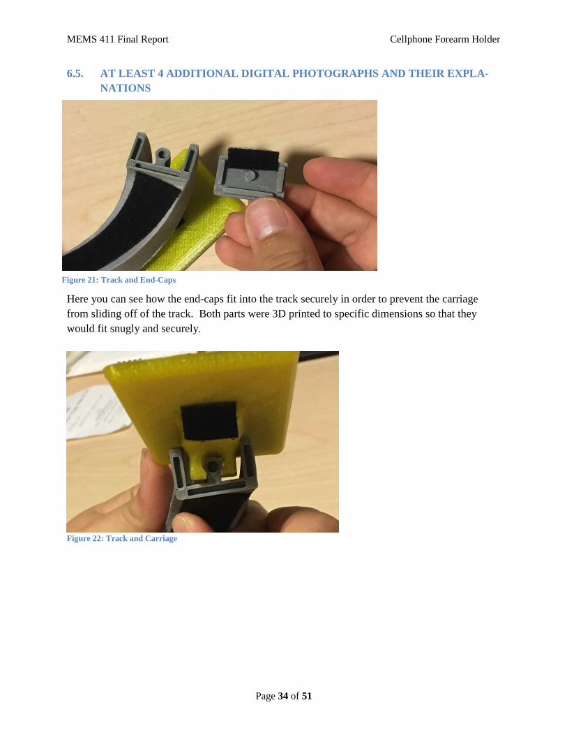
6.5. AT LEAST 4 ADDITIONAL DIGITAL PHOTOGRAPHS AND THEIR EXPLA-
NATIONS
Here you can see how the end-caps fit into the track securely in order to prevent the carriage
from sliding off of the track. Both parts were 3D printed to specific dimensions so that they
would fit snugly and securely.
Figure 22: Track and Carriage
Figure 21: Track and End-Caps
MEMS 411 Final Report Cellphone Forearm Holder
Page 35 of 51
Here you can see how the carriage fits onto the track so that it can slide all the way from one end
to the other. Both parts were 3D printed to specific dimensions so that the carriage would slide
along the track without coming off.
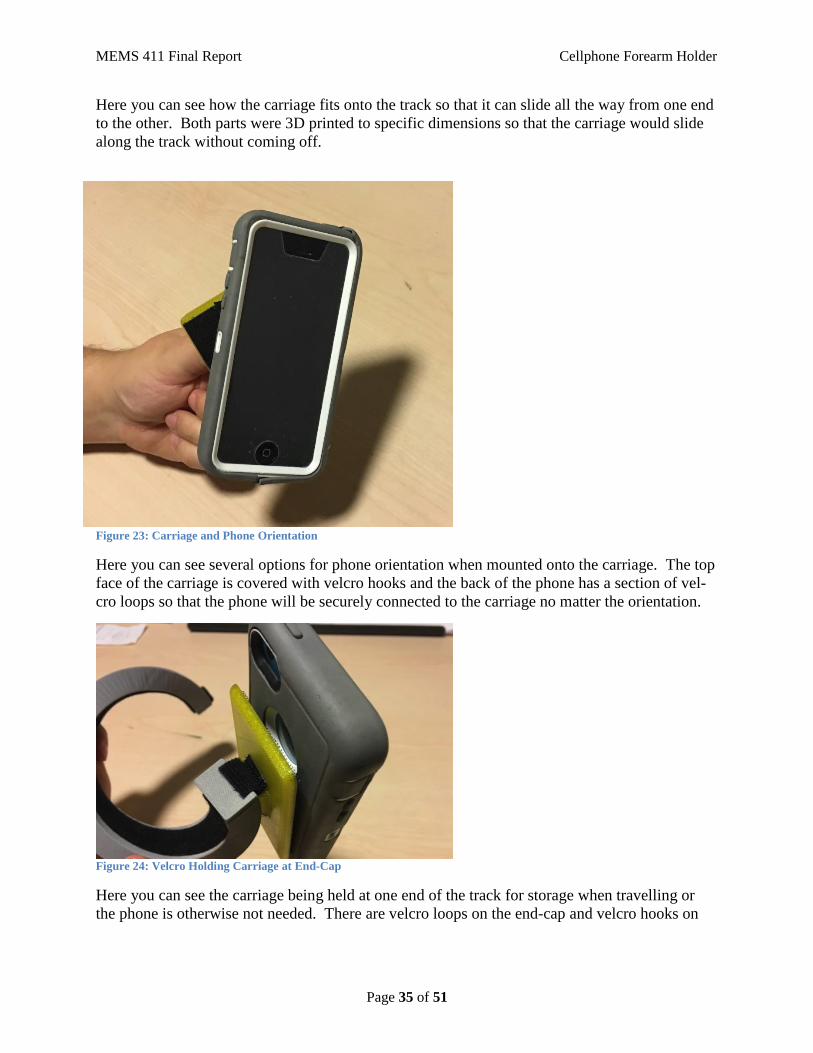
Figure 23: Carriage and Phone Orientation
Here you can see several options for phone orientation when mounted onto the carriage. The top
face of the carriage is covered with velcro hooks and the back of the phone has a section of vel-
cro loops so that the phone will be securely connected to the carriage no matter the orientation.
Figure 24: Velcro Holding Carriage at End-Cap
Here you can see the carriage being held at one end of the track for storage when travelling or
the phone is otherwise not needed. There are velcro loops on the end-cap and velcro hooks on

MEMS 411 Final Report Cellphone Forearm Holder
Page 36 of 51
the underside of the carriage so that the carriage will easily stay at the end-cap for an indefinite
amount of time.

MEMS 411 Final Report Cellphone Forearm Holder
Page 37 of 51
7. DESIGN DOCUMENTATION
7.1. FINAL DRAWINGS AND DOCUMENTATION
7.1.1. ENGINEERING DRAWINGS
Figure 25: SolidWorks Drawing of Variable Radius Holster

MEMS 411 Final Report Cellphone Forearm Holder
Page 38 of 51
Figure 26: SolidWorks Drawing of Case-to-Arm Attachment with Dimensions

MEMS 411 Final Report Cellphone Forearm Holder
Page 39 of 51
Figure 27: SolidWorks Drawing of Variable Radius Holster End Piece with Dimensions
Figure 28: SolidWorks drawing of Final Assembly with Bill of Materials

MEMS 411 Final Report Cellphone Forearm Holder
Page 40 of 51
Figure 29: Alternate SolidWorks Drawing of Variable Radius Holster
MEMS 411 Final Report Cellphone Forearm Holder
Page 41 of 51
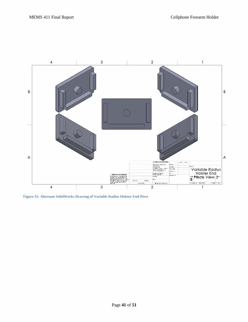
Figure 31: Alternate SolidWorks Drawing of Variable Radius Holster End Piece

MEMS 411 Final Report Cellphone Forearm Holder
Page 42 of 51
Figure 32: Alternate SolidWorks Drawing of Case-To-Arm-Attachment

MEMS 411 Final Report Cellphone Forearm Holder
Page 43 of 51
7.1.2. Sourcing instructions
Table 4: Final Parts List
# Parts Needed: Part Name: Source: Catalog Number Part Use:
1 Variable Radius
Holster
3D Printed N/A Main body of part
& track
1 Carriage 3D Printed N/A Holds phone to
track
2 Variable Radius
Holster End Pieces
3D Printed N/A Keeps carriage
from falling off
track
1 Velcro Michael’s N/A Attach assembly to
forearm, attach
phone to carriage,
hold carriage at
end caps
Table 5: Part Sourcing Instructions
Part Name: Source: Catalogue #: Price Each: Total Price: Sourcing
Instructions:
Variable
Radius Holster
3D Printed N/A Free Free SolidWorks
2015 used to
model parts,
3D printer used
to print parts
with ABS
plastic
Carriage 3D Printed N/A Free Free SolidWorks
2015 used to
model parts,
3D printer used
to print parts
with ABS
plastic
MEMS 411 Final Report Cellphone Forearm Holder
Page 44 of 51
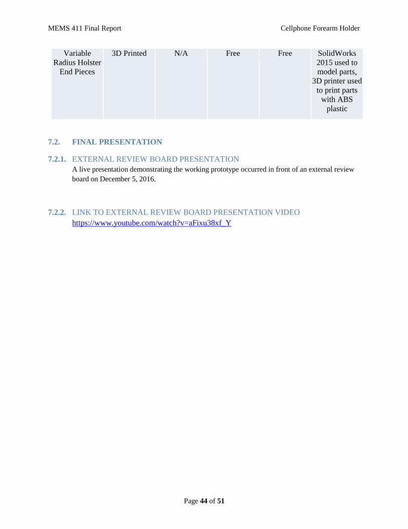
Variable
Radius Holster
End Pieces
3D Printed N/A Free Free SolidWorks
2015 used to
model parts,
3D printer used
to print parts
with ABS
plastic
7.2. FINAL PRESENTATION
7.2.1. EXTERNAL REVIEW BOARD PRESENTATION
A live presentation demonstrating the working prototype occurred in front of an external review
board on December 5, 2016.
7.2.2. LINK TO EXTERNAL REVIEW BOARD PRESENTATION VIDEO
https://www.youtube.com/watch?v=aFixu38xf_Y
MEMS 411 Final Report Cellphone Forearm Holder
Page 45 of 51
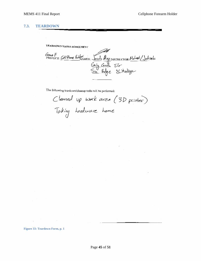
7.3. TEARDOWN
Figure 33: Teardown Form, p. 1

MEMS 411 Final Report Cellphone Forearm Holder
Page 46 of 51
Figure 34: Teardown Form, p. 2
8. DISCUSSION
8.1. USING THE FINAL PROTOTYPE PRODUCED TO OBTAIN VALUES FOR
METRICS, EVALUATE THE QUANTIFIED NEEDS EQUATIONS FOR THE
DESIGN. HOW WELL WERE THE NEEDS MET? DISCUSS THE RESULT.
When comparing the design metrics in Table 6 to Table 1, it is clear that there have been
some changes between the preliminary concept design and the final design. The main
change was that a new metric was added to more accurately capture the fact that the final
design is a helix with a variable radius. In other words, the radii of the two ends of the
final design are not the same. Specifically, one end of the final design has a radius of 4
in. while the other end of the final design has a radius of 3 in. As we expected, since
there are more metrics in Table 6 than in Table 1, the final value is larger. However, if
we take each final number and normalize them, 1.625 from Table 1 and 2.115 from Table
6, then we get 0.325 and 0.3525 respectively. These values show that all of the needs
were met to within 65% of a perfect world. The metric that threw off our final normal-
ized value was the number of sharp edges in the final design. Due to the specific manu-
facturing method that we chose, 3D printing, even after filleting every edge on the model,
sharp edges were still present. The most relevant fix, in regards to our project, would be
to sand down these edges until the edges weren't sharp anymore. Another possible fix
could be to enlarge the radius of the filleting in the model and reprint the affected parts.
MEMS 411 Final Report Cellphone Forearm Holder
Page 47 of 51
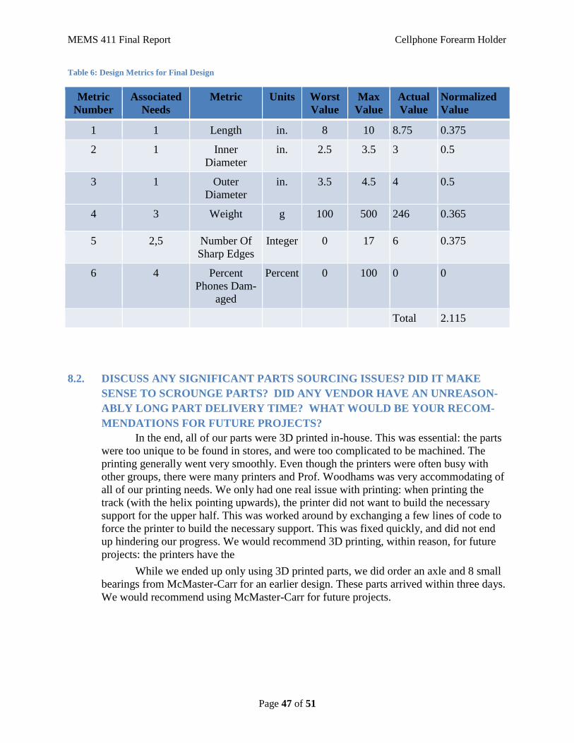
Table 6: Design Metrics for Final Design
Metric
Number
Associated
Needs
Metric Units Worst
Value
Max
Value
Actual
Value
Normalized
Value
1 1 Length in. 8 10 8.75 0.375
2 1 Inner
Diameter
in. 2.5 3.5 3 0.5
3 1 Outer
Diameter
in. 3.5 4.5 4 0.5
4 3 Weight g 100 500 246 0.365
5 2,5 Number Of
Sharp Edges
Integer 0 17 6 0.375
6 4 Percent
Phones Dam-
aged
Percent 0 100 0 0
Total 2.115
8.2. DISCUSS ANY SIGNIFICANT PARTS SOURCING ISSUES? DID IT MAKE
SENSE TO SCROUNGE PARTS? DID ANY VENDOR HAVE AN UNREASON-
ABLY LONG PART DELIVERY TIME? WHAT WOULD BE YOUR RECOM-
MENDATIONS FOR FUTURE PROJECTS?
In the end, all of our parts were 3D printed in-house. This was essential: the parts
were too unique to be found in stores, and were too complicated to be machined. The
printing generally went very smoothly. Even though the printers were often busy with
other groups, there were many printers and Prof. Woodhams was very accommodating of
all of our printing needs. We only had one real issue with printing: when printing the
track (with the helix pointing upwards), the printer did not want to build the necessary
support for the upper half. This was worked around by exchanging a few lines of code to
force the printer to build the necessary support. This was fixed quickly, and did not end
up hindering our progress. We would recommend 3D printing, within reason, for future
projects: the printers have the
While we ended up only using 3D printed parts, we did order an axle and 8 small
bearings from McMaster-Carr for an earlier design. These parts arrived within three days.
We would recommend using McMaster-Carr for future projects.

MEMS 411 Final Report Cellphone Forearm Holder
Page 48 of 51
8.3. DISCUSS THE OVERALL EXPERIENCE:
8.3.1. Was the project more of less difficult than you had expected?
The project was more difficult than we had expected. Particularly, we had many difficul-
ties using SolidWorks; many aspects of the design were far beyond the scope of what we
had studied in previous classes, and anything we had experience with. Our first design
roadblock was with the track: it was difficult to figure out how to keep the cross-section
of the track perpendicular to the helix. Our issues with the design aspect of SolidWorks
compounded when it came to the Motion Simulation aspect of the project. It took much
more time than expected to figure out how to mate the carriage with the track, as the key-
hole of the carriage has a flat interior surface, and the track is curved.
8.3.2. Does your final project result align with the project description?
Our final project aligns very closely with the project description: we ended up
building a holster that wraps around the forearm. The phone can move up and down the
track, staying indefinitely at either end as we initially stipulated. The only part of the pro-
ject description that we did not align with was the ability of the phone to rotate while
connected to the carriage: it has to be taken off the carriage and reattached. However, this
is not a significant failing, as the rotation ability was never a core aspect of our design de-
scription.
8.3.3. Did your team function well as a group?
Our team functioned fairly well as a group. There were times when we disagreed on the
goals of the project, but we were always able to have productive discussions about how to
move forward.
8.3.4. Were your team member’s skills complementary?
Yes; Sinclair enjoyed working on the CAD models and simulations, and was willing to
spend a lot of time working out the kinks in the projects. Emily was adept at predicting
problem spots in the design, and also was able to solve some of the sticky SolidWorks is-
sues. Jacob was particularly good at creatively coming up with solutions to problem spots
in the design, streamlining the workflow, and taking the initiative with the report.
8.3.5. Did your team share the workload equally?
It was sometimes difficult to work collaboratively on SolidWorks files, but regardless the
team shared the workload as equally as possible.
MEMS 411 Final Report Cellphone Forearm Holder
Page 49 of 51
8.3.6. Was any needed skill missing from the group?
As previously stated, we ran into SolidWorks issues that stretched the bounds of our
skills. We had to learn skills that were not required of us in our CAD class. While this
skill was initially missing, we learned it along with way.
8.3.7. Did you have to consult with your customer during the process, or did you work to the
original design brief?
We consulted with the customer at the beginning of the design process, and created the
original design brief from that. We were able to work off of the design brief for the vast
majority of the process, but consulted the customer again during preliminary design, to
affirm the importance of several design parameters.
8.3.8. Did the design brief (as provided by the customer) seem to change during the process?
The design brief did not change during the process.
8.3.9. Has the project enhanced your design skills?
Yes, we feel like we have a better understanding of how designs change with respect to
briefs and requirements. We’ve learned how to determine when a design change is need-
ed, and when it is inappropriate.
8.3.10. Would you now feel more comfortable accepting a design project assignment at a job?
We would feel much more comfortable accepting a design project assignment- especially
with the new skills in design revision. We also feel that after struggling through the road-
blocks, we have significantly more skills with SolidWorks.
8.3.11. Are there projects that you would attempt now that you would not attempt before?
We do not have any projects in mind that we would attempt now but would not have be-
fore. However, we would like to mention that if we came across a project that involved
creating CAD models and 3D printing, we would definitely be more likely to attempt
them now than we would have before.
MEMS 411 Final Report Cellphone Forearm Holder
Page 50 of 51
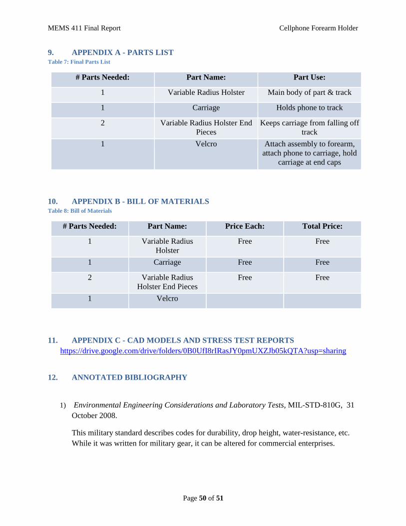
9. APPENDIX A - PARTS LIST Table 7: Final Parts List
# Parts Needed: Part Name: Part Use:
1 Variable Radius Holster Main body of part & track
1 Carriage Holds phone to track
2 Variable Radius Holster End
Pieces
Keeps carriage from falling off
track
1 Velcro Attach assembly to forearm,
attach phone to carriage, hold
carriage at end caps
10. APPENDIX B - BILL OF MATERIALS Table 8: Bill of Materials
# Parts Needed: Part Name: Price Each: Total Price:
1 Variable Radius
Holster
Free Free
1 Carriage Free Free
2 Variable Radius
Holster End Pieces
Free Free
1 Velcro
11. APPENDIX C - CAD MODELS AND STRESS TEST REPORTS
https://drive.google.com/drive/folders/0B0UfI8rIRasJY0pmUXZJb05kQTA?usp=sharing
12. ANNOTATED BIBLIOGRAPHY
1) Environmental Engineering Considerations and Laboratory Tests, MIL-STD-810G, 31
October 2008.
This military standard describes codes for durability, drop height, water-resistance, etc.
While it was written for military gear, it can be altered for commercial enterprises.