
Chapter 8 Poultry. Chicken Poultry 92erY8&feature=BFa&list=PLAE38AF98D17DC68C&index=34
34-1
GROUP 34 INDEX
STRUCTURE AND OPERATION 1. Rear Suspension Elements............................................................34-2
TROUBLESHOOTING ....................................................................... 34-3
SHOCK ABSORBER ......................................................................... 34-4
LEAF SPRING ................................................................................... 34-6
STABILIZER .................................................................................... 34-22
STRUCTURE AND OPERATION
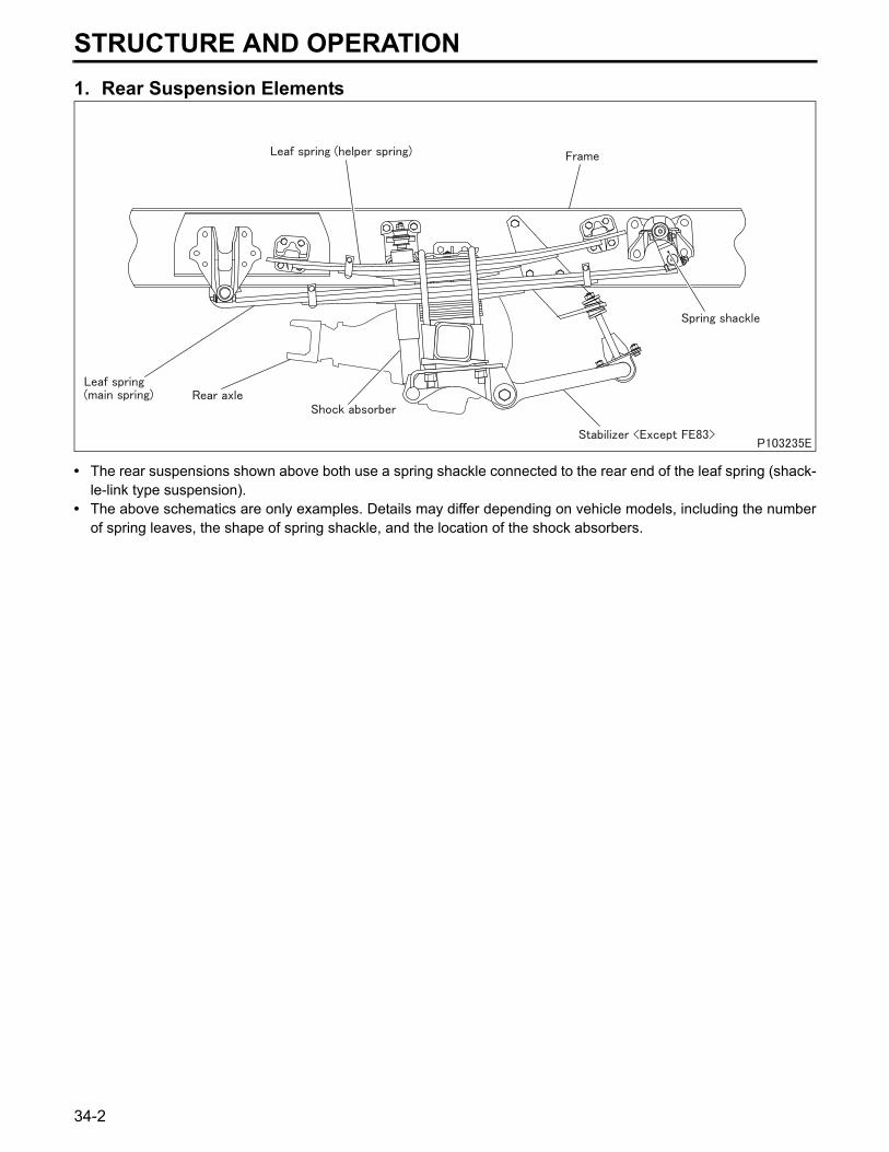
1. Rear Suspension Elements• The rear suspensions shown above both use a spring shackle connected to the rear end of the leaf spring (shack-le-link type suspension).
• The above schematics are only examples. Details may differ depending on vehicle models, including the numberof spring leaves, the shape of spring shackle, and the location of the shock absorbers.
34-2
34TROUBLESHOOTING
SymptomsFeel
s as
if fl
oatin
g
Tend
s to
be
nois
y
Roa
d bu
mps
/pits
rece
ived
as
shoc
ks
Hea
vy ro
lling
Cyc
lical
sho
cks
from
und
erne
ath
Exc
essi
ve ro
lling
whi
le c
ruis
ing
Reference Gr
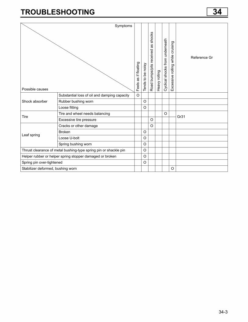
Possible causes
Shock absorber
Substantial loss of oil and damping capacity O
Rubber bushing worn O
Loose fitting O
TireTire and wheel needs balancing O
Gr31Excessive tire pressure O
Leaf spring
Cracks or other damage O
Broken O
Loose U-bolt O
Spring bushing worn O
Thrust clearance of metal bushing-type spring pin or shackle pin O
Helper rubber or helper spring stopper damaged or broken O
Spring pin over-tightened O
Stabilizer deformed, bushing worn O
34-3
SHOCK ABSORBER
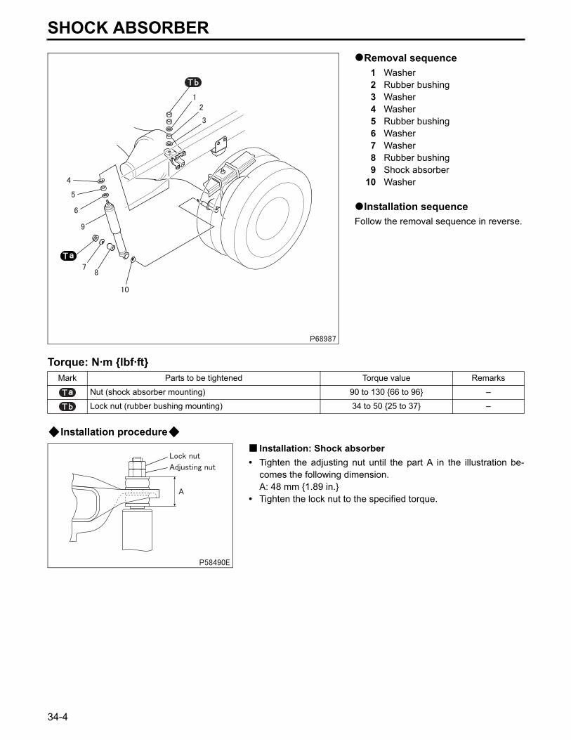
Removal sequence1 Washer2 Rubber bushing3 Washer4 Washer5 Rubber bushing6 Washer7 Washer8 Rubber bushing9 Shock absorber
10 Washer
Installation sequenceFollow the removal sequence in reverse.
Torque: N·m {lbf·ft}
Installation procedureInstallation: Shock absorber
• Tighten the adjusting nut until the part A in the illustration be-comes the following dimension.A: 48 mm {1.89 in.}
• Tighten the lock nut to the specified torque.
Mark Parts to be tightened Torque value Remarks
Nut (shock absorber mounting) 90 to 130 {66 to 96} –
Lock nut (rubber bushing mounting) 34 to 50 {25 to 37} –
34-4

M E M O
34
34-5
LEAF SPRING
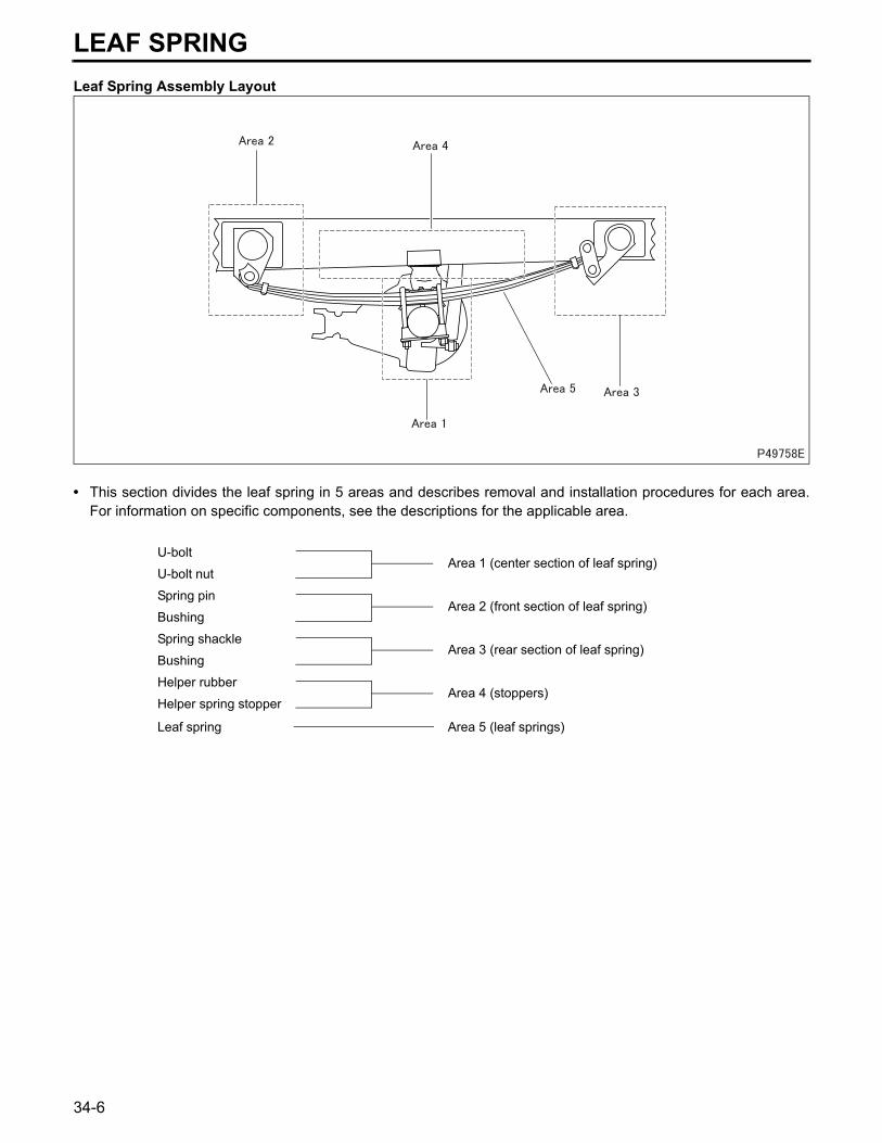
Leaf Spring Assembly Layout• This section divides the leaf spring in 5 areas and describes removal and installation procedures for each area.For information on specific components, see the descriptions for the applicable area.
U-boltArea 1 (center section of leaf spring)
U-bolt nut
Spring pinArea 2 (front section of leaf spring)
Bushing
Spring shackleArea 3 (rear section of leaf spring)
Bushing
Helper rubberArea 4 (stoppers)
Helper spring stopper
Leaf spring Area 5 (leaf springs)
34-6
34
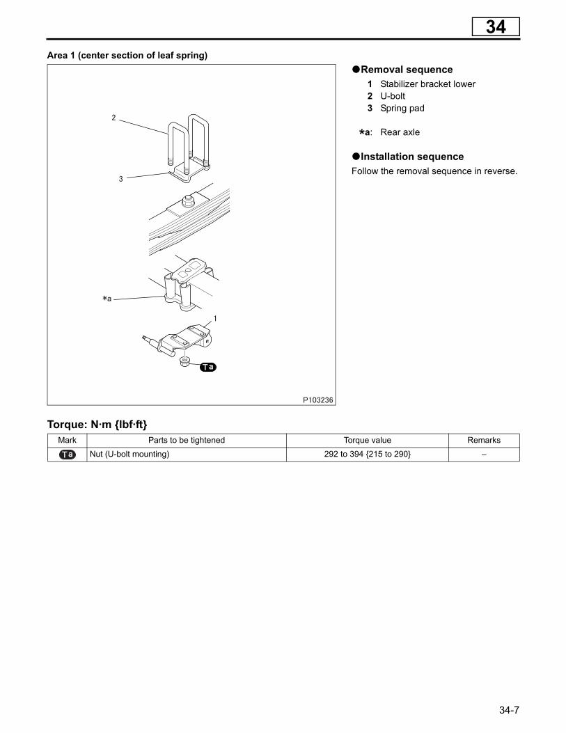
Area 1 (center section of leaf spring)Removal sequence1 Stabilizer bracket lower 2 U-bolt 3 Spring pad
*a: Rear axle
Installation sequenceFollow the removal sequence in reverse.
Torque: N·m {lbf·ft}Mark Parts to be tightened Torque value Remarks
Nut (U-bolt mounting) 292 to 394 {215 to 290} –
34-7
LEAF SPRING
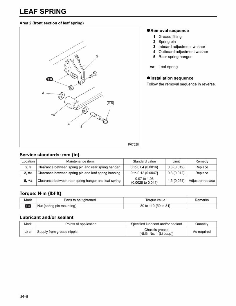
Area 2 (front section of leaf spring)Removal sequence1 Grease fitting2 Spring pin3 Inboard adjustment washer4 Outboard adjustment washer5 Rear spring hanger
*a: Leaf spring
Installation sequenceFollow the removal sequence in reverse.
Service standards: mm {in}
Torque: N·m {lbf·ft}
Lubricant and/or sealant
Location Maintenance item Standard value Limit Remedy
2, 5 Clearance between spring pin and rear spring hanger 0 to 0.04 {0.0016} 0.3 {0.012} Replace
2, *a Clearance between spring pin and leaf spring bushing 0 to 0.12 {0.0047} 0.3 {0.012} Replace
5, *a Clearance between rear spring hanger and leaf spring 0.07 to 1.03{0.0028 to 0.041} 1.3 {0.051} Adjust or replace
Mark Parts to be tightened Torque value Remarks
Nut (spring pin mounting) 80 to 110 {59 to 81} –
Mark Points of application Specified lubricant and/or sealant Quantity
Supply from grease nipple Chassis grease[NLGI No. 1 (Li soap)] As required
34-8
34
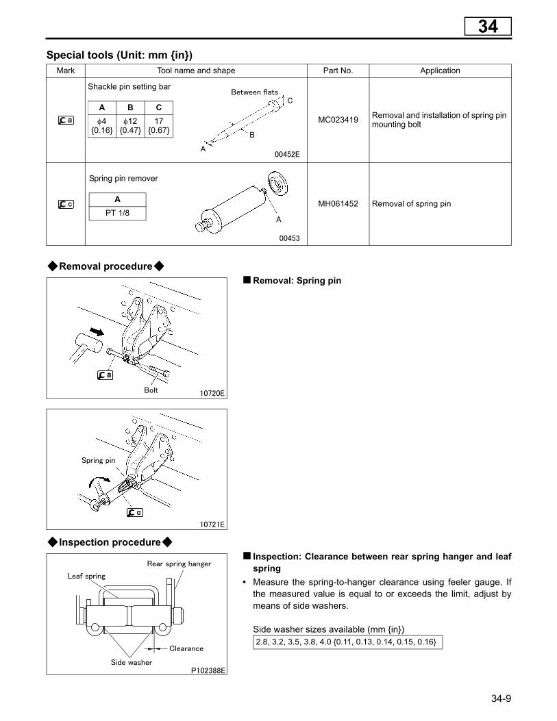
Special tools (Unit: mm {in})Removal procedureRemoval: Spring pin
Inspection procedureInspection: Clearance between rear spring hanger and leafspring
• Measure the spring-to-hanger clearance using feeler gauge. Ifthe measured value is equal to or exceeds the limit, adjust bymeans of side washers.
Side washer sizes available (mm {in})
Mark Tool name and shape Part No. Application
MC023419 Removal and installation of spring pin mounting bolt
MH061452 Removal of spring pin
2.8, 3.2, 3.5, 3.8, 4.0 {0.11, 0.13, 0.14, 0.15, 0.16}
Shackle pin setting bar
A B Cφ4
{0.16}φ12
{0.47}17
{0.67}
Spring pin remover
APT 1/8
34-9
LEAF SPRING
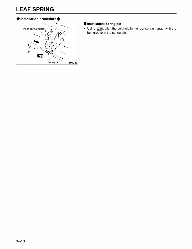
Installation procedureInstallation: Spring pin• Using , align the bolt hole in the rear spring hanger with the
bolt groove in the spring pin.
34-10

M E M O
34
34-11
LEAF SPRING
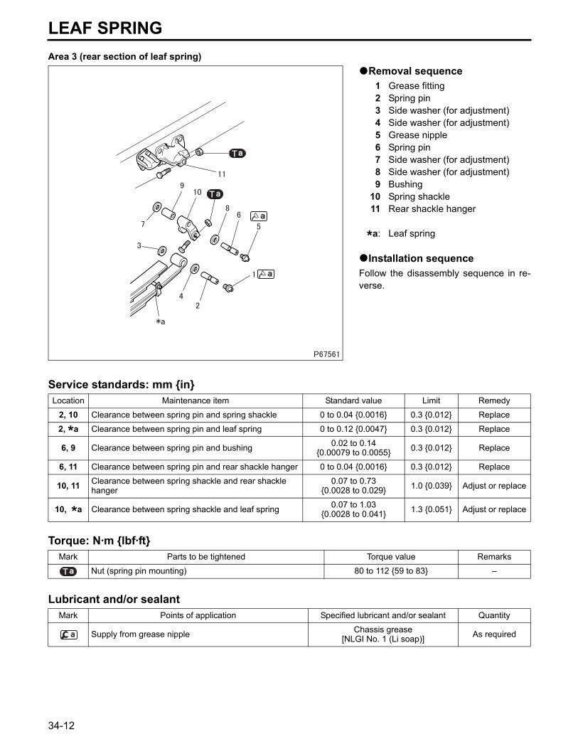
Area 3 (rear section of leaf spring)Removal sequence1 Grease fitting2 Spring pin3 Side washer (for adjustment)4 Side washer (for adjustment)5 Grease nipple6 Spring pin7 Side washer (for adjustment)8 Side washer (for adjustment)9 Bushing
10 Spring shackle11 Rear shackle hanger
*a: Leaf spring
Installation sequenceFollow the disassembly sequence in re-verse.
Service standards: mm {in}
Torque: N·m {lbf·ft}
Lubricant and/or sealant
Location Maintenance item Standard value Limit Remedy
2, 10 Clearance between spring pin and spring shackle 0 to 0.04 {0.0016} 0.3 {0.012} Replace
2, *a Clearance between spring pin and leaf spring 0 to 0.12 {0.0047} 0.3 {0.012} Replace
6, 9 Clearance between spring pin and bushing 0.02 to 0.14{0.00079 to 0.0055} 0.3 {0.012} Replace
6, 11 Clearance between spring pin and rear shackle hanger 0 to 0.04 {0.0016} 0.3 {0.012} Replace
10, 11 Clearance between spring shackle and rear shackle hanger
0.07 to 0.73{0.0028 to 0.029} 1.0 {0.039} Adjust or replace
10, *a Clearance between spring shackle and leaf spring 0.07 to 1.03{0.0028 to 0.041} 1.3 {0.051} Adjust or replace
Mark Parts to be tightened Torque value Remarks
Nut (spring pin mounting) 80 to 112 {59 to 83} –
Mark Points of application Specified lubricant and/or sealant Quantity
Supply from grease nipple Chassis grease[NLGI No. 1 (Li soap)] As required
34-12

34
Special tools (Unit: mm {in})Removal procedureRemoval: Spring pin
Removal: Spring pin
Mark Tool name and shape Part No. Application
MC023419 Removal and installation of spring pin mounting bolt
MH061452 Removal of spring pin
Shackle pin setting bar
A B Cφ4
{0.16}φ12
{0.47}17
{0.67}
Spring pin remover
APT 1/8
34-13
LEAF SPRING
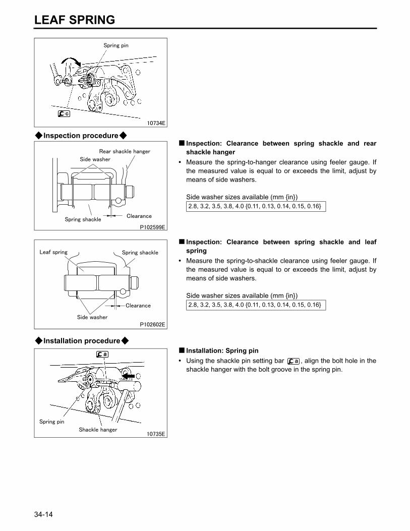
Inspection procedureInspection: Clearance between spring shackle and rearshackle hanger
• Measure the spring-to-hanger clearance using feeler gauge. Ifthe measured value is equal to or exceeds the limit, adjust bymeans of side washers.
Side washer sizes available (mm {in})
Inspection: Clearance between spring shackle and leafspring
• Measure the spring-to-shackle clearance using feeler gauge. Ifthe measured value is equal to or exceeds the limit, adjust bymeans of side washers.
Side washer sizes available (mm {in})
Installation procedureInstallation: Spring pin
• Using the shackle pin setting bar , align the bolt hole in theshackle hanger with the bolt groove in the spring pin.
2.8, 3.2, 3.5, 3.8, 4.0 {0.11, 0.13, 0.14, 0.15, 0.16}
2.8, 3.2, 3.5, 3.8, 4.0 {0.11, 0.13, 0.14, 0.15, 0.16}
34-14
34
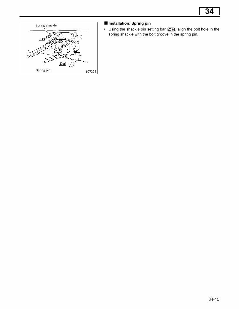
Installation: Spring pin• Using the shackle pin setting bar , align the bolt hole in thespring shackle with the bolt groove in the spring pin.
34-15
LEAF SPRING
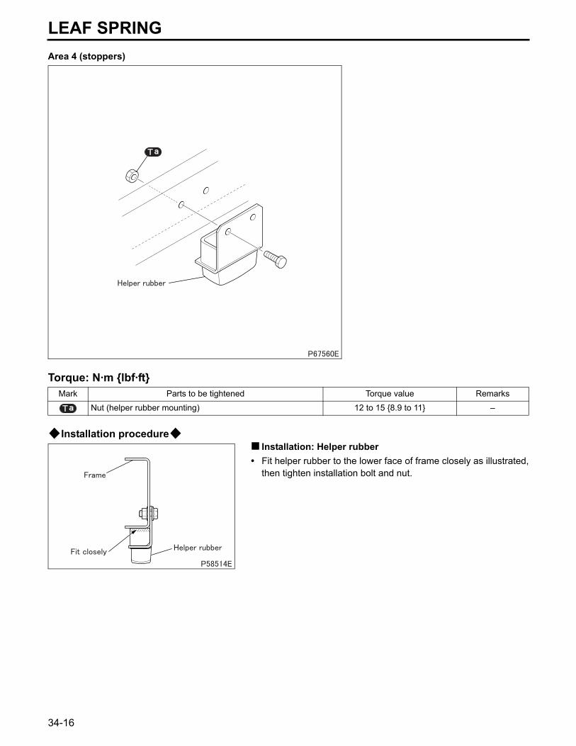
Area 4 (stoppers)Torque: N·m {lbf·ft}
Installation procedureInstallation: Helper rubber
• Fit helper rubber to the lower face of frame closely as illustrated,then tighten installation bolt and nut.
Mark Parts to be tightened Torque value Remarks
Nut (helper rubber mounting) 12 to 15 {8.9 to 11} –
34-16

M E M O
34
34-17
LEAF SPRING
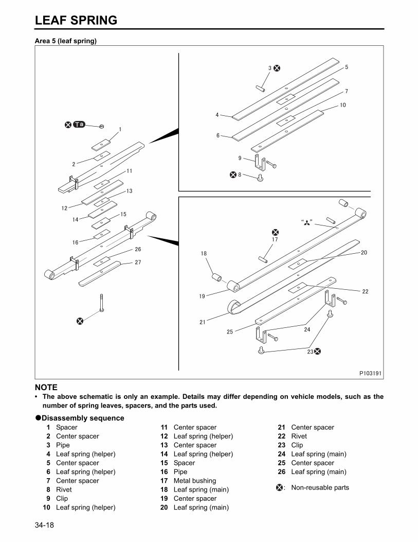
Area 5 (leaf spring)NOTE• The above schematic is only an example. Details may differ depending on vehicle models, such as the
number of spring leaves, spacers, and the parts used.
Disassembly sequence1 Spacer2 Center spacer3 Pipe4 Leaf spring (helper)5 Center spacer6 Leaf spring (helper)7 Center spacer8 Rivet9 Clip
10 Leaf spring (helper)
11 Center spacer12 Leaf spring (helper)13 Center spacer14 Leaf spring (helper)15 Spacer16 Pipe17 Metal bushing18 Leaf spring (main)19 Center spacer20 Leaf spring (main)
21 Center spacer22 Rivet23 Clip24 Leaf spring (main)25 Center spacer26 Leaf spring (main)
: Non-reusable parts
34-18
34
Assembly sequenceFollow the disassembly sequence in reverse.
Torque: N·m {lbf·ft}
Special tools (Unit: mm {in})
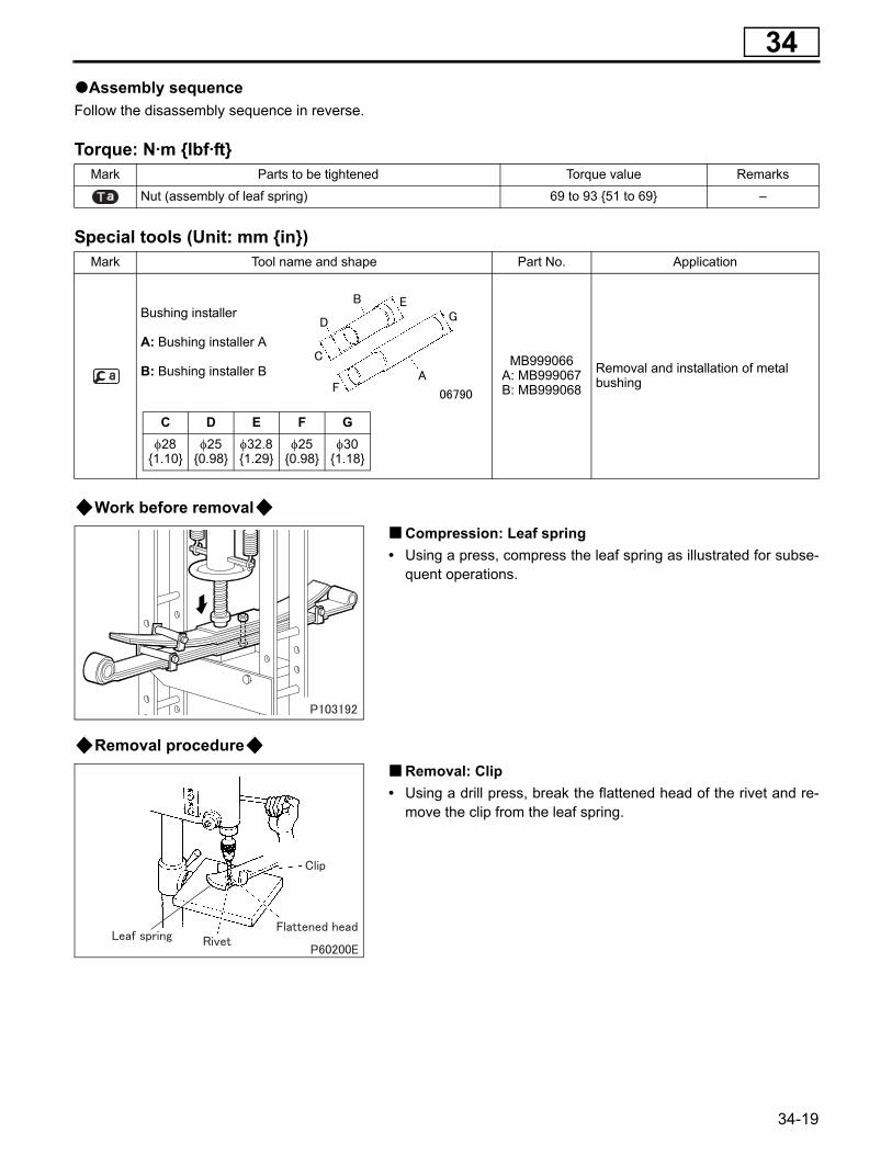
Work before removalCompression: Leaf spring
• Using a press, compress the leaf spring as illustrated for subse-quent operations.
Removal procedureRemoval: Clip
• Using a drill press, break the flattened head of the rivet and re-move the clip from the leaf spring.
Mark Parts to be tightened Torque value Remarks
Nut (assembly of leaf spring) 69 to 93 {51 to 69} –
Mark Tool name and shape Part No. Application
Bushing installer
A: Bushing installer A
B: Bushing installer BMB999066
A: MB999067B: MB999068
Removal and installation of metal bushing
C D E F Gφ28
{1.10}φ25
{0.98}φ32.8{1.29}
φ25{0.98}
φ30{1.18}
34-19
LEAF SPRING
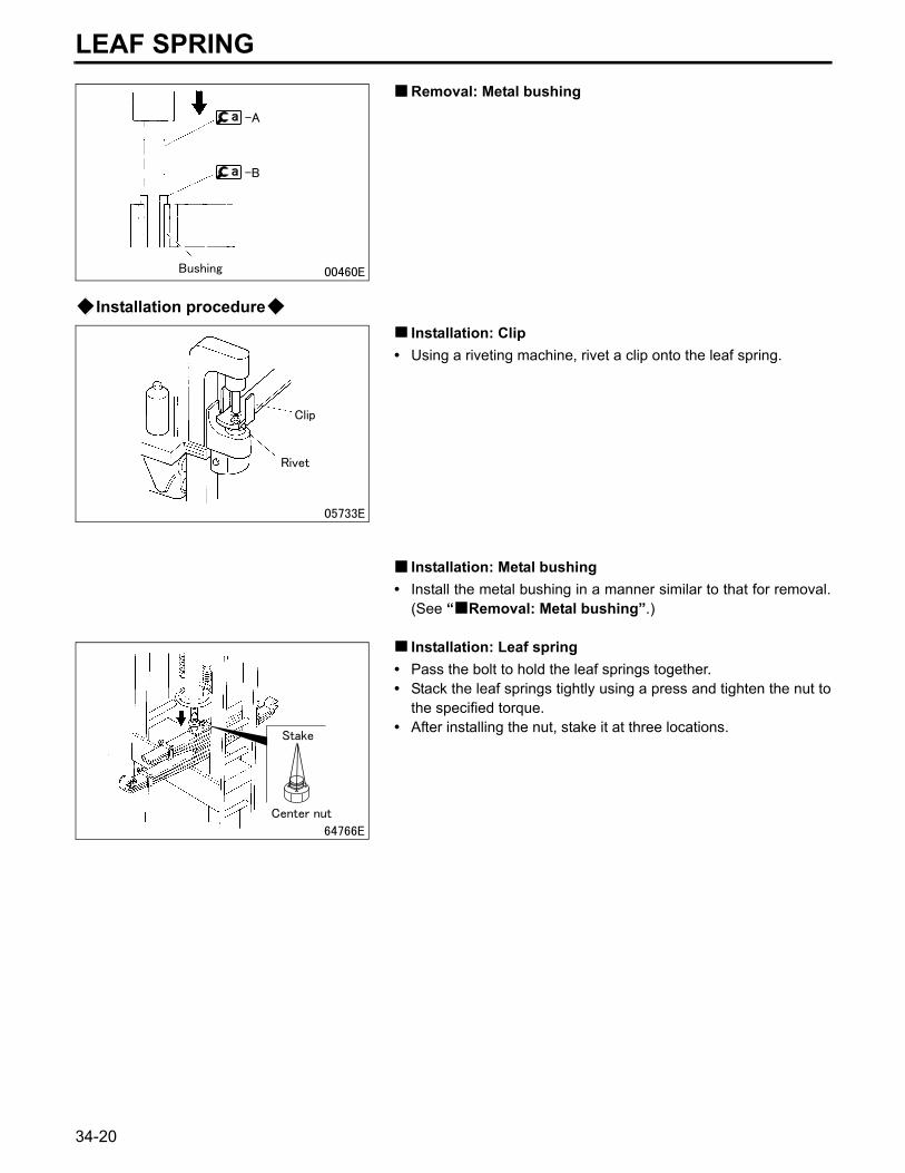
Removal: Metal bushingInstallation procedureInstallation: Clip
• Using a riveting machine, rivet a clip onto the leaf spring.
Installation: Metal bushing• Install the metal bushing in a manner similar to that for removal.
(See “ Removal: Metal bushing”.)
Installation: Leaf spring• Pass the bolt to hold the leaf springs together.• Stack the leaf springs tightly using a press and tighten the nut to
the specified torque.• After installing the nut, stake it at three locations.
34-20

M E M O
34
34-21
STABILIZER
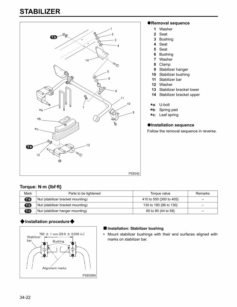
Removal sequence1 Washer2 Seat3 Bushing4 Seat5 Seat6 Bushing7 Washer8 Clamp9 Stabilizer hanger
10 Stabilizer bushing11 Stabilizer bar12 Washer13 Stabilizer bracket lower14 Stabilizer bracket upper
*a: U-bolt
*b: Spring pad
*c: Leaf spring
Installation sequenceFollow the removal sequence in reverse.
Torque: N·m {lbf·ft}
Installation procedureInstallation: Stabilizer bushing
• Mount stabilizer bushings with their end surfaces aligned withmarks on stabilizer bar.
Mark Parts to be tightened Torque value Remarks
Nut (stabilizer bracket mounting) 410 to 550 {300 to 405} –
Nut (stabilizer bracket mounting) 130 to 180 {96 to 130} –
Nut (stabilizer hanger mounting) 60 to 80 {44 to 59} –
34-22
34
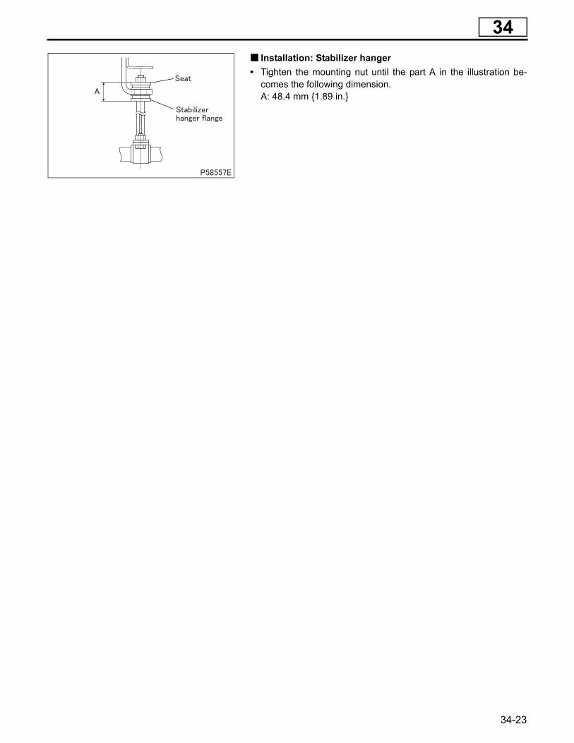
Installation: Stabilizer hanger• Tighten the mounting nut until the part A in the illustration be-comes the following dimension.A: 48.4 mm {1.89 in.}
34-23


![INDEX [] · 2020-01-21 · 338 Index Carter, Jimmy (continued)Africa and, 160–61 Reagan and, 13 USSR and, 63, 67 Carter-Brezhnev Project, 158 Casey, William, 34, 65, 68 in Group](https://static.fdocuments.us/doc/165x107/5f9e8b3ea6b0a309812918b7/index-2020-01-21-338-index-carter-jimmy-continuedafrica-and-160a61-reagan.jpg)


![Index []...Index Index 1 RESISTANCE THERMOMETERS 34 GÜNTHER GmbH Temperature Measurement Technology GÜNTHER Temperature Sensors in Action Principles of Temperature Measurement ...](https://static.fdocuments.us/doc/165x107/60bb10b973d4582e864f0710/index-index-index-1-resistance-thermometers-34-goenther-gmbh-temperature.jpg)


![Index []...Index 1 Mahindra Hotels and Residences India Limited 1 2 Gables Promoters Private Limited 15 3 MH Boutique Hospitality Limited 34 4 Infinity Hospitality Group Company Limited](https://static.fdocuments.us/doc/165x107/5e3b4f881c37c647c5240153/index-index-1-mahindra-hotels-and-residences-india-limited-1-2-gables-promoters.jpg)


