GROUP 23Aa - Mirage...
36
23Aa-1 GROUP 23Aa CONTENTS GENERAL DESCRIPTION. . . . . . . . . 23Aa-2 SPECIAL TOOLS . . . . . . . . . . . . . . . . 23Aa-10 ON-VEHICLE SERVICE . . . . . . . . . . . 23Aa-12 A/T CONTROL COMPONENT LAYOUT . . 23Aa-12 ESSENTIAL SERVICE . . . . . . . . . . . . . . . . 23Aa-13 A/T FLUID CHECK . . . . . . . . . . . . . . . . . . . 23Aa-13 A/T FLUID REPLACEMENT . . . . . . . . . . . . 23Aa-14 FLUSHING COOLERS AND TUBES . . . . . 23Aa-16 OIL COOLER FLOW CHECK . . . . . . . . . . . 23Aa-17 TP SENSOR ADJUSTMENT . . . . . . . . . . . 23Aa-17 PARK/NEUTRAL POSITION SWITCH CONTINUITY CHECK. . . . . . . . . . . . . . . . . 23Aa-18 PARK/NEUTRAL POSITION SWITCH AND CONTROL CABLE ADJUSTMENT. . . . . . . 23Aa-18 AUTOMATIC TRANSAXLE CONTROL COMPONENT CHECK . . . . . . . . . . . . . . . . 23Aa-19 CRANKSHAFT POSITION SENSOR CHECK . . . . . . . . . . . . . . . . . . . . . . . . . . . . 23Aa-19 TP SENSOR CHECK . . . . . . . . . . . . . . . . . 23Aa-19 A/T FLUID TEMPERATURE SENSOR CONTINUITY CHECK. . . . . . . . . . . . . . . . . 23Aa-19 PARK/NEUTRAL POSITION SWITCH CHECK . . . . . . . . . . . . . . . . . . . . . . . . . . . . 23Aa-20 STOPLIGHT SWITCH CHECK . . . . . . . . . . 23Aa-20 DUAL PRESSURE SWITCH CHECK . . . . . 23Aa-20 A/T CONTROL RELAY CHECK . . . . . . . . . 23Aa-20 SOLENOID VALVE CHECK . . . . . . . . . . . . 23Aa-21 SELECTOR LEVER OPERATION CHECK . . . . . . . . . . . . . . . . . . . . . . . . . . . . 23Aa-22 KEY INTERLOCK MECHANISM CHECK . . 23Aa-23 SHIFT LOCK MECHANISM CHECK . . . . . . 23Aa-23 TRANSAXLE CONTROL CABLE ADJUSTMENT . . . . . . . . . . . . . . . . . . . . . . 23Aa-24 TRANSAXLE CONTROL* . . . . . . . . . 23Aa-25 REMOVAL AND INSTALLATION . . . . . . . . 23Aa-25 INSPECTION. . . . . . . . . . . . . . . . . . . . . . . . 23Aa-26 DISASSEMBLY AND ASSEMBLY . . . . . . . 23Aa-27 A/T KEY INTERLOCK AND SHIFT LOCK MECHANISMS* . . . . . . . . . . . . 23Aa-28 REMOVAL AND INSTALLATION . . . . . . . . 23Aa-28 INSPECTION. . . . . . . . . . . . . . . . . . . . . . . . 23Aa-29 TRANSAXLE ASSEMBLY . . . . . . . . . 23Aa-30 REMOVAL AND INSTALLATION . . . . . . . . 23Aa-30 SPECIFICATIONS . . . . . . . . . . . . . . . 23Aa-35 FASTENER TIGHTENING SPECIFICATIONS. . . . . . . . . . . . . . . . . . . . 23Aa-35 SERVICE SPECIFICATIONS . . . . . . . . . . . 23Aa-36 LUBRICANT . . . . . . . . . . . . . . . . . . . . . . . . 23Aa-36 WARNINGS REGARDING SERVICING OF SUPPLEMENTAL RESTRAINT SYSTEM (SRS) EQUIPPED VEHICLES WARNING • Improper service or maintenance of any component of the SRS, or any SRS-related component, can lead to personal injury or death to service personnel (from inadvertent firing of the air bag) or to the driver and passenger (from rendering the SRS inoperative). • Service or maintenance of any SRS component or SRS-related component must be performed only at an authorized MITSUBISHI dealer. • MITSUBISHI dealer personnel must thoroughly review this manual, and especially its GROUP 52B - Supplemental Restraint System (SRS) before beginning any service or maintenance of any component of the SRS or any SRS- related component. NOTE The SRS includes the following components: SRS air bag control unit, SRS warning light, front impact sensors, air bag module, clock spring, and interconnecting wiring. Other SRS-related components (that may have to be removed/installed in connection with SRS service or maintenance) are indicated in the table of contents by an asterisk (*).
Transcript of GROUP 23Aa - Mirage...

23Aa-1
GROUP 23Aa
CONTENTS
GENERAL DESCRIPTION. . . . . . . . . 23Aa-2
SPECIAL TOOLS. . . . . . . . . . . . . . . . 23Aa-10
ON-VEHICLE SERVICE. . . . . . . . . . . 23Aa-12A/T CONTROL COMPONENT LAYOUT . . 23Aa-12ESSENTIAL SERVICE . . . . . . . . . . . . . . . . 23Aa-13A/T FLUID CHECK . . . . . . . . . . . . . . . . . . . 23Aa-13A/T FLUID REPLACEMENT . . . . . . . . . . . . 23Aa-14FLUSHING COOLERS AND TUBES . . . . . 23Aa-16OIL COOLER FLOW CHECK . . . . . . . . . . . 23Aa-17TP SENSOR ADJUSTMENT . . . . . . . . . . . 23Aa-17PARK/NEUTRAL POSITION SWITCH CONTINUITY CHECK. . . . . . . . . . . . . . . . . 23Aa-18PARK/NEUTRAL POSITION SWITCH AND CONTROL CABLE ADJUSTMENT. . . . . . . 23Aa-18AUTOMATIC TRANSAXLE CONTROL COMPONENT CHECK . . . . . . . . . . . . . . . . 23Aa-19CRANKSHAFT POSITION SENSOR CHECK . . . . . . . . . . . . . . . . . . . . . . . . . . . . 23Aa-19TP SENSOR CHECK . . . . . . . . . . . . . . . . . 23Aa-19A/T FLUID TEMPERATURE SENSOR CONTINUITY CHECK. . . . . . . . . . . . . . . . . 23Aa-19PARK/NEUTRAL POSITION SWITCH CHECK . . . . . . . . . . . . . . . . . . . . . . . . . . . . 23Aa-20STOPLIGHT SWITCH CHECK. . . . . . . . . . 23Aa-20DUAL PRESSURE SWITCH CHECK. . . . . 23Aa-20
A/T CONTROL RELAY CHECK . . . . . . . . . 23Aa-20SOLENOID VALVE CHECK . . . . . . . . . . . . 23Aa-21SELECTOR LEVER OPERATION CHECK . . . . . . . . . . . . . . . . . . . . . . . . . . . . 23Aa-22KEY INTERLOCK MECHANISM CHECK . . 23Aa-23SHIFT LOCK MECHANISM CHECK. . . . . . 23Aa-23TRANSAXLE CONTROL CABLE ADJUSTMENT . . . . . . . . . . . . . . . . . . . . . . 23Aa-24
TRANSAXLE CONTROL* . . . . . . . . . 23Aa-25REMOVAL AND INSTALLATION . . . . . . . . 23Aa-25INSPECTION. . . . . . . . . . . . . . . . . . . . . . . . 23Aa-26DISASSEMBLY AND ASSEMBLY . . . . . . . 23Aa-27
A/T KEY INTERLOCK AND SHIFT LOCK MECHANISMS* . . . . . . . . . . . . 23Aa-28
REMOVAL AND INSTALLATION . . . . . . . . 23Aa-28INSPECTION. . . . . . . . . . . . . . . . . . . . . . . . 23Aa-29
TRANSAXLE ASSEMBLY . . . . . . . . . 23Aa-30REMOVAL AND INSTALLATION . . . . . . . . 23Aa-30
SPECIFICATIONS . . . . . . . . . . . . . . . 23Aa-35FASTENER TIGHTENING SPECIFICATIONS. . . . . . . . . . . . . . . . . . . . 23Aa-35SERVICE SPECIFICATIONS . . . . . . . . . . . 23Aa-36LUBRICANT . . . . . . . . . . . . . . . . . . . . . . . . 23Aa-36
WARNINGS REGARDING SERVICING OF SUPPLEMENTAL RESTRAINT SYSTEM (SRS) EQUIPPED VEHICLES
WARNING• Improper service or maintenance of any component of the SRS, or any SRS-related component, can lead to
personal injury or death to service personnel (from inadvertent firing of the air bag) or to the driver and passenger (from rendering the SRS inoperative).
• Service or maintenance of any SRS component or SRS-related component must be performed only at an authorized MITSUBISHI dealer.
• MITSUBISHI dealer personnel must thoroughly review this manual, and especially its GROUP 52B - Supplemental Restraint System (SRS) before beginning any service or maintenance of any component of the SRS or any SRS-related component.
NOTEThe SRS includes the following components: SRS air bag control unit, SRS warning light, front impact sensors, air bag module,clock spring, and interconnecting wiring. Other SRS-related components (that may have to be removed/installed in connectionwith SRS service or maintenance) are indicated in the table of contents by an asterisk (*).

GENERAL DESCRIPTIONAUTOMATIC TRANSAXLE23Aa-2
. GENERAL DESCRIPTIONM1231000100236
The A/T come in one model, namely, F4A42.
TRANSAXLEThe transaxle is made up of the torque converter and gear train. A 3-element, 1-step, 2-phase torque con-verter with built-in torque converter clutch is used. The gear train is made up of three sets of multi-plate clutches, two sets of multi-plate brakes, one set of one-way clutches and two sets of planetary gears. The planetary gears are made up of sun gears, carriers, pinion gears and annulus gears..
ITEM SPECIFICATIONTransaxle model F4A42Engine model 4G94 (2.0L Engine)Torque converter Type 3-element, 1-stage, 2-phase
Torque converter clutch Provided (3rd to 4th)Stall torque ratio 2.0
Transaxle type 4-speed forward, 1-speed reverse fully automaticGear ratio 1st 2.842
2nd 1.4953rd 1.0004th 0.731Reverse 2.720
Final gear ratio (Differential gear ratio) 3.735Number of underdrive clutch discs 4Number of overdrive clutch discs 4Number of reverse clutch discs 2Number of low-reverse brake discs 5Number of second brake discs 3Manual control type P-R-N-D-3-2-L (7 positions)Shift pattern control Electronic control (INVECS-II)Oil pressure control during shifting Electronic control (each oil pressure independently
controlled)Torque converter clutch control Electronic controlSpeedometer gear ratio 29/36
TSB Revision

GENERAL DESCRIPTIONAUTOMATIC TRANSAXLE 23Aa-3
TRANSAXLE CONFIGURATION DRAWING
.
COMPONENTS AND FUNCTIONS
FUNCTION ELEMENT TABLE
AC001813
ODREV 2ND LR
OWCUD
AB
COMPONENT FUNCTIONUnderdrive clutch UD connects the input shaft to the underdrive sun gear.Reverse clutch REV connects the input shaft to the reverse sun gear.Overdrive clutch OD connects the input shaft to the overdrive planetary carrier.Low-reverse brake LR holds the low-reverse annulus gear and the overdrive planetary
carrier.Second brake 2ND holds the reverse sun gear.One-way clutch OWC restricts the rotation direction of the low-reverse annulus gear.
OPERATING ELEMENT ENGINE START
PARKING MECHANISM
UNDERDRIVE CLUTCH (UD)
REVERSE CLUTCH (REV)
OVER-DRIVE CLUTCH (OD)
LOW-REVERSE BRAKE (LR)
SECOND BRAKE (2ND)SELECTOR LEVER
POSITION
P Parking OK × − − − × −R Reverse − − − × − × −N Neutral OK − − − − × −D 1st − − × − − ×* −
2nd − − × − − − ×3rd − − × − × − −4th − − − − × − ×
3 1st − − × − − ×* −2nd − − × − − − ×3rd − − × − × − −
TSB Revision

GENERAL DESCRIPTIONAUTOMATIC TRANSAXLE23Aa-4
×: Function elementNOTE: * operates only when the vehicle is stationary [at approximately 10 km/h (6.2 mph) or less].
2 1st − − × − − ×* −2nd − − × − − − ×
L 1st − − × − − × −
OPERATING ELEMENT ENGINE START
PARKING MECHANISM
UNDERDRIVE CLUTCH (UD)
REVERSE CLUTCH (REV)
OVER-DRIVE CLUTCH (OD)
LOW-REVERSE BRAKE (LR)
SECOND BRAKE (2ND)SELECTOR LEVER
POSITION
TSB Revision

GENERAL DESCRIPTIONAUTOMATIC TRANSAXLE 23Aa-5
SECTIONAL VIEW
AC005936
21 54 63 7 98 10
17
14
18
19
AB
11
12
13
15
16
1. OVERDRIVE CLUTCH 2. REVERSE CLUTCH 3. OVERDRIVE PLANETARY CARRIER 4. SECOND BRAKE 5. LOW-REVERSE BRAKE 6. OUTPUT PLANETARY CARRIER 7. ONE-WAY CLUTCH 8. TRANSFER DRIVE GEAR 9. UNDERDRIVE CLUTCH 10. TRANSAXLE CASE
11. TORQUE CONVERTER 12. TORQUE CONVERTER CLUTCH 13. INPUT SHAFT 14. OIL PUMP 15. TORQUE CONVERTER HOUSING 16. DIFFERENTIAL
17. TRANSFER DRIVEN GEAR18. OUTPUT SHAFT19. REAR COVER
TSB Revision

GENERAL DESCRIPTIONAUTOMATIC TRANSAXLE23Aa-6
ELECTRONICALLY-CONTROLLED SYSTEM.INVECS-II• When in drive ("D" range), the new automatic transaxle
employs an innovative shift schedule to provide a high level of comfort and "easy driving style" that matches all driving conditions as well as the driver's driving style.
• INVECS-II features "Optimum Shift Control," which provides shift timing the average driver perceives to be the optimum timing under any road conditions. "Adaptive Shift Control" adjusts shift timing to match the driving habits and prefer-ences of individual drivers.
.
FEATURESOPTIMUM SHIFT CONTROL1. The shift patterns found satisfying by the typical driver for all
ranges of driving are stored in the computer's memory. The computer uses this data to analyze road conditions and the driver's style of operation, and then outputs the optimal shift patterns stored in its memory to best match the conditions.
2. We introduce the latest in control technologies with an inno-vative new algorithm called the "neural network" that works to imitate the decision-making processes of the human brain. The neural network links a wide variety of input data regarding road and operating conditions, and instantly makes accurate shift control decisions.
.
ADAPTIVE SHIFT CONTROL1. The computer learns the driving habits and pref-
erences of each individual driver by processing driving data on engine output, tire load, foot brake operation, etc. It then uses this data to adjust shift timing to best suit the driver's style.
2. If the computer determines from the driving pat-terns that the driver is one who enjoys a relaxed, unhurried style, it adjusts timing to execute up-shifts at a lower engine speed to provide a smooth, quiet ride. On the other hand, if the com-puter determines the driver to prefer a sporty ride, it adjusts timing to shift up at a higher engine speed to provide more powerful response.
AC000841AB
WITH INVECS-IIWITHOUTINVECS-II
OPTIMUM SELECTION OF GEARS
LEVEL ROAD
ALL DRIVING CONDITIONS
DRIVER'S HABITS ANDPREFERENCE
AC000842
ACCELERATORPOSITION
VEHICLE SPEED
FOOT BRAKE
OPTIMUMGEARSELECTION
MANUAL SHIFTOPERATIONDATA OF ANUMBERDRIVER'S
DECISION
ROADCONDITIONAND DRIVINGOPERATION
COMPUTER
OPTIMUM CONTROL
AB
AC000843
ACCELERATORPOSITION
VEHICLE SPEED
FOOT BRAKE
OPTIMUMGEARSELECTION
DATAPROCESSED
INTERRE-LATED
DECI-SION
COMPUTER
NEURAL NETWORK
AB
TSB Revision

GENERAL DESCRIPTIONAUTOMATIC TRANSAXLE 23Aa-7
3. If the computer determines that the driver tends to apply the brakes often on a descending road-way, it adjusts timing to down shift sooner so that engine braking is more effectively applied. Con-versely, if the computer determines that the driver does not brake much while driving downhill, it delays downshifting to minimize the effect of engine braking.
.
AC000844
DRIVER WHO PREFERSRELAXING RIDE
DRIVER WHO PREFERSSPORTIER RIDE
50 (31)
4TH3RD
100 (62)
VEHICLE SPEED [km/h (mph)]
ADAPTIVE SHIFT CONTROL DURING ACCELERATION
AB
4TH3RD
AC000845
DRIVER WHO PRESSESBRAKE PEDAL OFTEN
AVERAGE DRIVER 4TH
3RD
ADAPTIVE SHIFT CONTROL ON DOWNGRADES
AB
4TH3RD4TH
4TH
4TH
4TH
3RD
2ND
DRIVER WHO RARELYPRESSES THE BRAKE
CONVENTIONAL A/T (NO DOWN SHIFT)
NEW A/T WITHINVECS-II
TSB Revision

GENERAL DESCRIPTIONAUTOMATIC TRANSAXLE23Aa-8
SYSTEM CONSTRUCTION DIAGRAM
Powertrain control module (PCM)Ignition switch
Input shaft speed sensor
Output shaft speed sensor
Crankshaft position sensor
Throttle position sensor
A/T fluid temperature sensor
Park/Neutral position switch
Dual pressure switch
Stoplight switch
Cruise control unit (OD OFF Signal)
Scan tool (MUT-II)
Serial communication
A/T control relay
Torque converter clutch solenoid valve
Low-reverse solenoid valve
Second solenoid valve
Underdrive solenoid valve
Overdrive solenoid valve
SENSE DECIDE ACT
AC006183AB
TSB Revision

GENERAL DESCRIPTIONAUTOMATIC TRANSAXLE 23Aa-9
SHIFT PATTERN CONTROL.
UPSHIFT PATTERN
NOTE: Within 2 -to- 3 and 3 -to- 4 movement ranges, the PCM adjusts shift points according to the driving conditions by memorizing the accelerator pedal stroke and braking timing..
DOWNSHIFT PATTERN
AC006095
THROTTLEOPENING (%)100
50
0 1,000 2,000 3,000 4,000 5,000 6,000 7,000
1 2 2 3 3 4
0 (0) 50(31) 100 (62) 150 (93) 200 (124)
OUTPUT SHAFT SPEED (r/min)
VEHICLE SPEED [km/h (mph)]
THICK LINE: STANDARD SHIFT PATTERN
AB
2 → 3MOVEMENTRANGE
3 → 4MOVEMENTRANGE
THROTTLEOPENINGVOLTAGE (V)
0.41
1.00
2.00
3.00
4.66
AC006096AB
100
50
0 1,000 2,000 3,000 4,000 5,000 6,000 7,000OUTPUT SHAFT SPEED (r/min)
0 (0) 50 (31) 100 (62) 150 (93) 200 (124)
VEHICLE SPEED [km/h (mph)]
1 2
1 2 (L)
2 3 3 4
2 3 (L, 2) 3 4 (L, 2, 3)
THROTTLEOPENING (%)
THROTTLEOPENINGVOLTAGE (V)
0.41
1.00
2.00
3.00
4.00
4.66
TSB Revision

SPECIAL TOOLSAUTOMATIC TRANSAXLE23Aa-10
SPECIAL TOOLSM1231000600219
TOOL TOOL NUMBER AND NAME
SUPERSESSION APPLICATION
MD998330 (Includes MD998331)Oil pressure gauge (3.0 MPa, 427 psi)
MD998330-01 Measurement of hydraulic pressure
MD998332Adapter
MD998332-01 Connection for oil pressure gauge
MD998478Test harness (3 pin, triangle)
MD998478-01 Inspection using an oscilloscope
MB991502Scan tool (MUT-II)
MB991496-OD Checking diagnostic trouble codes
MB991709Test harness set
Tool not available Inspection using an oscilloscope
MD998900Adapter
MD998900-01 Connection for oil pressure gauge
MB995062Flushing tool
MLR-6906B or Equivalent
Flushing cooler and tube
B991502
TSB Revision

SPECIAL TOOLSAUTOMATIC TRANSAXLE 23Aa-11
MB991453Engine hanger assembly
MZ203827-01 When an engine lifer is used: Supporting the engine assembly during removal and installation of the transaxle
GENERAL SERVICE TOOL MZ203827Engine lifter
MZ203827-01
MB991454Engine hanger balancer
MZ203827-01 When the engine hanger is used: Supporting the engine assembly during removal and installation of the transaxle assemblyNOTE: Special tool MB991454 is a part of engine hanger attachment set MB991453.
MB991895Engine hanger
−
MB991897Ball joint remover
MB991113-01, MB990635-01 or general service tool
Knuckle and tie rod end ball joint breakaway torque checkNOTE: Steering linkage puller(MB990635 or MB991113)is also used to disconnect knuckle and tie rod end ball joint.
MB990241 Axle shaft pullerA: MB990244
Puller shaftB: MB990242
Puller bar
MB990241-01 or general service tool
Removal of the drive shaft
MB990767End yoke holder
MB990767-01 Fixing of the hub
MB990998Front hub remover and installer
MB990998-01 or general service tool
Provisional fixing of the wheel bearing
TOOL TOOL NUMBER AND NAME
SUPERSESSION APPLICATION
B991453
MZ203827
B991454
MB991895
AC106827
MB990241AB
A
B
B990767
MB990998
TSB Revision

ON-VEHICLE SERVICEAUTOMATIC TRANSAXLE23Aa-12
ON-VEHICLE SERVICEA/T CONTROL COMPONENT LAYOUT
M1231008600183
NAME SYMBOL NAME SYMBOLA/T control relay D Input shaft speed sensor CA/T control solenoid valves G Output shaft speed sensor CA/T fluid temperature sensor G Park/Neutral position (PNP) switch FCrankshaft position sensor A Powertrain control module (PCM) JData link connector I Stoplight switch HDual pressure switch E Throttle position sensor B
AC100144
A B C D
E F G H I JAF
AC100158
A
AD
CRANKSHAFTPOSITIONSENSOR
AC100156
B
AE
THROTTLEPOSITIONSENSOR
AC100203
C
AH
OUTPUTSHAFTSPEEDSENSOR
INPUT SHAFTSPEEDSENSOR
AC100766
A/T CONTROLRELAY
AD
D
TSB Revision

ON-VEHICLE SERVICEAUTOMATIC TRANSAXLE 23Aa-13
ESSENTIAL SERVICE
A/T FLUID CHECKM1231000900179
1. Drive the vehicle until the A/T fluid temperature rises to the normal temperature [70 − 80°C (158 − 176°F)].NOTE: The A/T fluid temperature is measured with scan tool MB991502 (MUT-II).NOTE: If it takes some amount of time until the A/T fluid reaches its normal operating temperature [70 − 80°C (158 − 176°F)], check the A/T fluid level by referring to the left dia-gram.
2. Park the vehicle on a level surface.3. Move the selector lever through all positions to fill the torque
converter and the hydraulic circuits with fluid, and then move the selector lever to the "N" position.
4. After wiping off any dirt around the dipstick, remove the dipstick and check the condition of the A/T fluid.
AC100168
E
DUALPRESSURESWITCH
AC AC006297AJ
F
PARK/NEUTRALPOSITION (PNP)SWITCH
AC004670
LOW-REVERSESOLENOID VALVE
VALVE BODYASSEMBLY
A/T FLUIDTEMPERATURESENSOR
UNDERDRIVESOLENOIDVALVEOVERDRIVE
SOLENOIDVALVE
SECONDSOLENOIDVALVE
TORQUECONVERTERSOLENOIDVALVE
G
AE AC004673
H
AB
STOPLIGHT SWITCH
BRAKE PEDAL
AC100188
I
DATA LINK CONNECTOR
AD AC100229
J
POWERTRAINCONTROLMODULE
AD
AC005860
80
DIPSTICK
6040(176)(140)(104)
FLUID TEMPERATURE [˚C (˚F)]
– 30 (– 1.2)
– 20 (– 0.8)
– 10 (– 0.4)
0 (0)
10 (0.4)FLUID LEVEL [mm (in)]
AB
TSB Revision

ON-VEHICLE SERVICEAUTOMATIC TRANSAXLE23Aa-14
NOTE: If the A/T fluid smells as if it is burnt, it means that the A/T fluid has been contaminated by fine particles from the bushings and friction materials. A transaxle overhaul and cooler line flushing may be necessary.
5. Check that the A/T fluid level is at the "HOT" mark on the dipstick. If the A/T fluid level is less than this, add DIAMOND ATF SP III or equivalent A/T fluid until the level reaches the "HOT" mark.NOTE: If the A/T fluid level is too low, the oil pump will draw in air along with the A/T fluid, which will cause bubbles to form. If the A/T fluid level is too high, rotating components inside the transaxle will churn the fluid and air into a foamy liquid. Both conditions (level too low or too high) will cause the hydraulic pressure to drop, which will result in late shift-ing and slipping of the clutches and brakes.NOTE: In either case, air bubbles can interfere with normal valve, clutch, and brake operation. Also, foaming can cause A/T fluid to escape from the transaxle vent where it may be mistaken for a leak.
6. Securely insert the dipstick.NOTE: The A/T fluid should always be replaced under the following conditions:.
• • When troubleshooting the transaxle.• • When overhauling the transaxle.• • When the A/T fluid is noticeably dirty or burnt (driving
under severe conditions).
A/T FLUID REPLACEMENTM1231001000179
If you have an A/T fluid changer, use this changer to replace the A/T fluid. If you do not have an A/T fluid changer, replace the A/T fluid by the following procedure.1. Disconnect the hose shown in the illustration which
connects the transaxle and the oil cooler (inside the radiator). Place a container under the hose to collect the discharge.CAUTION
The engine should be stopped within one minute after it is started. If all the A/T fluid has drained out before then, the engine should be stopped at that point.2. Start the engine and let the A/T fluid drain out.
(Running conditions: "N" range with engine idling)
Approximately 3.5 dm3 (3.7 quarts) of A/T fluid should be removed.
AC005861AB
AC005863
RADIATOR
AB
TSB Revision

ON-VEHICLE SERVICEAUTOMATIC TRANSAXLE 23Aa-15
3. Remove the drain plug from the bottom of the transaxle case to drain the A/T fluid.
Approximately 2.0 dm3 (2.1 quarts) of A/T fluid should be removed.
4. Install the drain plug with a new gasket, and tighten it to the specified torque.
Tightening torque: 32 ± 2 N⋅m (24 ± 1 ft-lb)
CAUTIONStop pouring if the full volume of A/T fluid can not be added.5. Add new A/T fluid (DIAMOND ATF SP III or equivalent)
through the oil filter tube.
Approximately 5.5 dm3 (5.8 quarts) of A/T fluid should be added.
6. Repeat the procedure in Step 2. (to pump out the rest of the contaminated A/T fluid)
7. Add new A/T fluid (DIAMOND ATF SP III or equivalent) through the oil filter tube.
Approximately 3.5 dm3 (3.7 quarts) of A/T fluid should be added.
NOTE: Check for contamination or a burnt odor. If the A/T fluid is still contaminated or burnt, repeat Steps 6 and 7 before proceeding to Step 8.
8. Reconnect the hose which was disconnected in step 1 above, and firmly replace the dipstick.
9. Start the engine and run it at idle for one to two minutes.10.Move the selector lever through all positions, and then move
it to the "N" position.
11.Check that the A/T fluid level is at the "COLD" mark on the dipstick. If the level is less than this, add A/T fluid.
12.Drive the vehicle until the A/T fluid temperature rises to the normal operating temperature [70 − 80°C (158 − 176°F)], and then check the A/T fluid level again. The A/T fluid level must be at the "HOT" mark.NOTE: The A/T fluid temperature is measured with scan tool MB991502 (MUT-II).NOTE: The "COLD" level is for reference only; the "HOT" level should be regarded as the standard level.
AC001890AB
AC005863
RADIATOR
AB
AC005861AB
TSB Revision

ON-VEHICLE SERVICEAUTOMATIC TRANSAXLE23Aa-16
NOTE: If it takes some amount of time until the A/T fluid reaches its normal operating temperature [70 − 80°C (158 − 176°F)], check the A/T fluid level by referring to the left dia-gram.
13.When the A/T fluid is less than the specified level, add A/T fluid.When the A/T fluid is greater than the specified level, drain the excess fluid through the drain plug to adjust the A/T fluid to the specified level.
14.Firmly insert the dipstick into the oil filler tube.
FLUSHING COOLERS AND TUBESM1231013000176
Required Special Tool:MB995062: Flushing Tool
WARNING• Wear protective eyewear that meets the require-
ments of ANSI Z87.1 − 1968 and OSHA. Wear stan-dard industrial rubber gloves.
• Keep lighted cigarettes, sparks, flames, and other ignition sources away from the area to prevent the ignition of combustible liquids and gases. Keep a class B fire extinguisher in the area where the flushing tool will be used. Keep the area well venti-lated. Do not let flushing solvent come in contact with eyes or skin. If it does, flush with water for 15 to 20 seconds. Remove contaminated clothing and wash affected skin with soap and water. Seek med-ical attention.
When a transaxle failure has contaminated the A/T fluid, the oil cooler(s) must be flushed. The cooler by-pass valve in the tran-saxle must also be replaced. The torque converter must also be replaced with an exchange unit. This will ensure that metal particles or sludged A/T fluid are not later transferred back into the reconditioned (or replaced) transaxle. There are two differ-ent procedures for flushing coolers and lines. The recom-mended procedure is to use special tool MB995062 Flushing Tool. The other procedure is to use a hand suction gun and mineral spirits.1. Remove the cover plate filler plug on special tool
MB995062. Fill the reservoir 1/2 to 3/4 full with fresh flushing solution. Flushing solvents are petroleum based solutions generally used to clean transaxle components. Do not use solvents containing acids, water, gasoline, or any other corrosive liquids.
2. Reinstall the filler plug on special tool MB995062.3. Verify that the pump power switch is turned "OFF." Connect
the red alligator clip to the positive battery terminal. Connect the black alligator clip to a good ground.
4. Disconnect the cooler lines at the transaxle.
AC005860
80
DIPSTICK
6040(176)(140)(104)
FLUID TEMPERATURE [˚C (˚F)]
– 30 (– 1.2)
– 20 (– 0.8)
– 10 (– 0.4)
0 (0)
10 (0.4)FLUID LEVEL [mm (in)]
AB
TSB Revision

ON-VEHICLE SERVICEAUTOMATIC TRANSAXLE 23Aa-17
NOTE: When flushing the transaxle cooler and lines, always reverse flush.
5. Connect the BLUE pressure line to the OUTLET line (from cooler).
6. Connect the CLEAR return line to the INLET line (to cooler).7. Turn the pump "ON" for two to three minutes to flush the
cooler(s) and lines. Monitor the pressure readings. Clear the return lines. Pressure readings should stabilize below 138 kPa (20 psi) for vehicles equipped with a single cooler and 208 kPa (30 psi) for vehicles equipped with dual coolers. If flow is intermittent or exceeds these pressures, replace the cooler(s).
8. Turn the pump "OFF."9. Disconnect the CLEAR suction line from the reservoir at the
cover plate. Disconnect the CLEAR return line at the cover plate and place it in a drain pan.
10.Turn the pump "ON" for 30 seconds to purge flushing solution from the cooler(s) and lines. Turn the pump "OFF."
11.Place the CLEAR suction line into a one quart container of DIAMOND ATF SP III or equivalent A/T fluid.
12.Turn the pump "ON" until all A/T fluid is removed from the one quart container and lines. This purges any residual cleaning solvent from the transaxle cooler(s) and lines. Turn the pump "OFF."
13.Disconnect the alligator clips from the battery. Reconnect the flusher lines to the cover plate, and remove the flushing adapters from the cooler lines. Reconnect the cooler lines.
OIL COOLER FLOW CHECKM1231013100151
After the new or repaired transaxle has been installed, fill to the proper level with DIAMOND ATF SP III or equivalent A/T fluid. The flow should be checked using the following procedure:
CAUTIONWith the fluid set at the proper level, A/T fluid collection should not exceed one quart or internal damage to the transaxle may occur.1. Disconnect the OUTLET line (from cooler) at the transaxle
and place a collecting container under the disconnected line.2. Run the engine at curb idle speed with the shift selector in
neutral.3. If A/T fluid flow is intermittent or it takes more than 20
seconds to collect one quart of A/T fluid, replace the cooler.4. If flow is within acceptable limits, reconnect the cooler line.
Then fill the transaxle to the proper level, using DIAMOND ATF SP III or equivalent A/T fluid.
TP SENSOR ADJUSTMENTM1231001900161
Refer to GROUP 13A, On-vehicle Service P.13Aa-12.
AC005864
TO COOLER FROMCOOLER
AB
AC005864
TO COOLER FROMCOOLER
AB
TSB Revision

ON-VEHICLE SERVICEAUTOMATIC TRANSAXLE23Aa-18
PARK/NEUTRAL POSITION SWITCH CONTINUITY CHECKM1231001400304
PARK/NEUTRAL POSITION SWITCH AND CONTROL CABLE ADJUSTMENT
M1231010300156
1. Set the selector lever to the "N" position.2. Loosen the control cable to the manual control lever
coupling nut to free the cable and lever.3. Set the manual control lever to the neutral position.
ITEM TERMINAL CONNECTION OF TESTER
SPECIFIED CONDITION
P 3 − 8, 9 − 10 Less than 2 ohms.
R 7 − 8
N 4 − 8, 9 − 10
D 1 − 8
3 5 − 8
2 2 − 8
L 6 − 8
AC006297DIPSTICK
PARK/NEUTRALPOSITION (PNP)SWITCH
AF
AC005865
PR
N
D
3
2
L
AB
AC006297
TRANSAXLE CONTROLCABLE
ADJUSTINGNUT
MANUAL CONTROLLEVER
AG
TSB Revision

ON-VEHICLE SERVICEAUTOMATIC TRANSAXLE 23Aa-19
4. Loosen the park/neutral position switch body mounting bolts and turn the park/neutral position switch body so the hole in the end of the manual control lever and the hole (section A − A in the figure on the left) in the flange of the park/neutral position switch body flange are aligned.NOTE: The park/neutral position switch body can be aligned by inserting a 5-mm diameter steel bar into the end hole of the manual control lever and the flange hole of the park/neu-tral position switch body.
5. Tighten the park/neutral position switch body mounting bolts to the specified torque. Be careful at this time that the switch body does not move.
Tightening torque: 11 ± 1 N⋅m (96 ± 8 in-lb)
6. Gently push the transaxle control cable in the direction of the arrow, until the cable is taut. Tighten the adjusting nut.
Tightening torque: 12 ± 2 N⋅m (107 ± 17 in-lb)7. Check that the selector lever is in the "N" position.8. Check that each position of the manual control lever
matches each position of the selector lever using scan tool MB991502.
AUTOMATIC TRANSAXLE CONTROL COMPONENT CHECK
CRANKSHAFT POSITION SENSOR CHECKM1231009000184
Refer to GROUP 13A, Diagnosis − Inspection Procedure Using an Oscilloscope P.13Ab-41.
TP SENSOR CHECKM1231003900167
Refer to GROUP 13A, On-vehicle Service − Throttle Position Sensor Check P.13Aa-20.
A/T FLUID TEMPERATURE SENSOR CONTINUITY CHECK
M1231004500162
1. Remove the A/T fluid temperature sensor.
AC005866AB
11 ± 1 N·m96 ± 8 in-lb
A
A
SECTION A - A
MOUNTINGBOLTS
MANUALCONTROL LEVER
HOLE IN END
HOLE INFLANGE
MANUALCONTROLLEVER
PARK/NEUTRALPOSITIONSWITCH BODY
AC006297
ADJUSTING NUT
12 ± 2 N·m107 ± 17 in-lb
MANUAL CONTROLLEVER
AH
TSB Revision

ON-VEHICLE SERVICEAUTOMATIC TRANSAXLE23Aa-20
2. Measure the resistance between terminals 1 and 2 of the A/T fluid temperature sensor connector.
Standard value:
3. If the A/T fluid temperature sensor resistance is outside the specified range and the "N" range indicator light is flashing, replace the A/T fluid temperature sensor.NOTE: The "N" range indicator light on the combination meter flashes when the temperature reaches approximately 125°C (257°F) or greater, and then stops flashing when the temperature drops below approximately 115°C (238°F).
PARK/NEUTRAL POSITION SWITCH CHECKM1231001400315
Refer to P.23Aa-18.
STOPLIGHT SWITCH CHECKM1231009100136
Refer to GROUP 35A, Brake Pedal − Brake Pedal Inspection P.35A-28.
DUAL PRESSURE SWITCH CHECKM1231004700144
Refer to GROUP 55, On-vehicle Service − Pressure Switch Check P.55-79.
A/T CONTROL RELAY CHECKM1231009300141
1. Remove the A/T control relay.
A/T FLUID TEMPERATURE RESISTANCE0°C (32°F) 16.7 − 20.5 kΩ
20°C (68°F) 7.3 − 8.9 kΩ
40°C (104°F) 3.4 − 4.2 kΩ
60°C (140°F) 1.9 − 2.2 kΩ
80°C (176°F) 1.0 − 1.2 kΩ
100°C (212°F) 0.57 − 0.69 kΩ
AC100601AB
ATF
AC100766AFBATTERY
A/T CONTROL RELAY
TSB Revision

ON-VEHICLE SERVICEAUTOMATIC TRANSAXLE 23Aa-21
2. Use jumper wires to connect A/T control relay terminal 3 to the negative battery terminal and terminal 2 to the positive battery terminal.
3. Check for continuity between A/T control relay terminals 1 and 4 when the jumper wires are connected to and disconnected from the battery.
4. If there is any problem with the A/T control relay, replace it.
SOLENOID VALVE CHECKM1231009400148
1. Use scan tool MB991502 to measure the A/T fluid temperature. The desired A/T fluid temperature setting for performing the solenoid valve check s 20°C (68°F).
2. Remove the A/T control solenoid valve assembly connector.3. Measure the resistance between the solenoid valve
terminals.4. The measured resistance of the solenoid valve when the A/
T fluid temperature is 20°C (68°F) should match the specified resistance on the chart below.
Specified resistance:
5. If the solenoid valve resistance is within the specified range, check the power supply and the ground circuits.
6. If the solenoid valve resistance is not within the specified range, drain the A/T fluid and remove the valve body cover.
JUMPER WIRE CONTINUITY BETWEEN TERMINALS NO.1 AND NO.4
Connected Continuity
Disconnected No continuityAC100115
1 23 4
FRONT OF VEHICLE
AJ
TERMINAL NO.
NAME RESISTANCE
No. 7 - No. 10 Torque converter clutch solenoid valve
2.7 − 3.4 Ω [at 20°C (68°F)]
No. 6 - No. 10 Low-reverse solenoid valve
No. 4 - No. 9 Second solenoid valve
No. 3 - No. 9 Underdrive solenoid valve
No. 5 - No. 9 Overdrive solenoid valve
AC100377
7 10531 2 4 6
98
A/T CONTROLSOLENOID VALVEASSEMBLY
AB
TSB Revision

ON-VEHICLE SERVICEAUTOMATIC TRANSAXLE23Aa-22
7. Disconnect the connector of any solenoid valves that are not within the specified range.
8. Measure the resistance between terminals 1 and 2 of any solenoid valve that was not within the specified range.
Specified resistance:2.7 − 3.4 Ω [at 20°C (68°F)]
9. If the resistance is not within the specified range, replace the solenoid valve.
10.If the resistance is within the specified range, check the wiring harness between the affected A/T control solenoid valve assembly and the solenoid valve. If a problem is not found in the above steps, check the solenoid valve O-rings and replace them if necessary.
SELECTOR LEVER OPERATION CHECKM1231001300255
1. Apply the parking brake, and check that the selector lever moves smoothly and accurately to each position.
2. Check that the engine starts when the selector lever is in the "N" or "P" position, and that it does not start when the selector lever is in any other position.
3. Start the engine, release the parking brake, and check that the vehicle moves forward when the selector lever is moved from the "N" position to the "D", "3", "2" or "L" position, and that the vehicle reverses when the selector lever is moved to the "R" position.
4. Stop the engine.5. Turn the ignition switch to the "ON" position, and check that
the backup lamp illuminates when the selector lever is shifted from the "P" to the "R" position.NOTE: The A/T mis-operation prevention mechanism pre-vents movement of the selector lever from the "P" position if the ignition switch is in a position other than "LOCK" (OFF) and the brake pedal is not depressed.
AC002219AD
LOW-REVERSESOLENOIDVALVE
OVERDRIVESOLENOIDVALVE
TORQUECONVERTERCLUTCHSOLENOID
SECONDSOLENOIDVALVE
UNDERDRIVESOLENOIDVALVE
AC100378
12
AB
3
2
AC100057AC
THE SELECTOR LEVER MOVES WHEN THE BRAKE PEDAL IS DEPRESSED AND THE BUTTON IS PUSHED IN WITH THE IGNITION KEY IN ANY POSITION OTHER THAN THE "LOCK" (OFF) POSITION.
THE SELECTOR LEVER MOVES WITHOUT PUSHING THE BUTTON.
THE SELECTOR LEVER MOVES WHEN THE BUTTON IS PUSHED.
TSB Revision

ON-VEHICLE SERVICEAUTOMATIC TRANSAXLE 23Aa-23
KEY INTERLOCK MECHANISM CHECKM1232000900235
1. Perform the following inspection.
2. When any of the above checks are not normal, adjust the key interlock cable by following procedure.(1) Remove the floor console. (Refer to GROUP 52A − Front
floor console P.52A-7.)(2) Shift the selector lever to "P" position.(3) Turn the ignition key to the "LOCK" (OFF) position.(4) Loosen the locking nut of the key interlock cable.(5) Push the cable joint on the lock cam gently toward the
arrow until the cable stops. Tighten the locking nut.Tightening torque: 12 ± 2 N⋅m (107 ± 17 in-lb)
(6) Install the floor console. (Refer to GROUP 52A − Front floor console P.52A-7.)
3. After adjusting, check the operation once more. If the operation is still incorrect, replace the key interlock cable. (Refer to P.23Aa-28.)
SHIFT LOCK MECHANISM CHECKM1232001000224
1. Perform the following inspections.
2. When any of the above shift lock inspection procedures fail, adjust the shift lock cable as follows:
INSPECTION PROCEDURE
INSPECTION REQUIREMENTS
KEY INTERLOCK (NORMAL OPERATION)
1 Brake pedal: Depressed
Ignition key position: "LOCK" (OFF) or removed
Unable to push in the selector lever push button and move the lever out of the "P" position.
2 Ignition key position: "ACC"
Able to push in the selector lever push button, move the lever out of the "P" position, and shift to any position.
3 Brake pedal: Not depressed
Selector lever: Other than "P" position
Unable to turn the ignition key to the "LOCK" (OFF) position.
4 Selector lever: "P" position Able to turn the ignition key to the "LOCK" (OFF) position.
AC0001627AB
LOCKINGNUT
KEY INTERLOCK CABLE LOCK CAM
INSPECTION PROCEDURE
INSPECTION REQUIREMENTS
CHECK DETAILS (NORMAL OPERATION)
1 Brake pedal: Not depressed
Ignition key position: "ACC"
When the selector lever push button is depressed, the selector lever can not be shifted out of the "P" position.
2 Brake pedal: Depressed
When the selector lever push button is depressed, the selector lever can be shifted smoothly to other positions.
3 Brake pedal: Not depressed
When the selector lever push button is depressed, the selector lever can be shifted smoothly from the "R" position to the "P position.
TSB Revision
ON-VEHICLE SERVICEAUTOMATIC TRANSAXLE23Aa-24
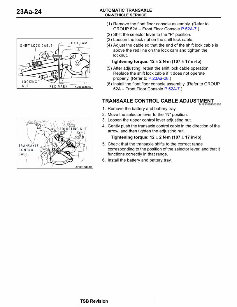
(1) Remove the flont floor console assembly. (Refer to GROUP 52A − Front Floor Console P.52A-7.)
(2) Shift the selector lever to the "P" position.(3) Loosen the lock nut on the shift lock cable.(4) Adjust the cable so that the end of the shift lock cable is
above the red line on the lock cam and tighten the locknut.
Tightening torque: 12 ± 2 N⋅m (107 ± 17 in-lb)(5) After adjusting, retest the shift lock cable operation.
Replace the shift lock cable if it does not operate properly. (Refer to P.23Aa-28.)
(6) Install the flont floor console assembly. (Refer to GROUP 52A − Front Floor Console P.52A-7.)
TRANSAXLE CONTROL CABLE ADJUSTMENTM1231028000020
1. Remove the battery and battery tray.2. Move the selector lever to the "N" position.3. Loosen the upper control lever adjusting nut.4. Gently push the transaxle control cable in the direction of the
arrow, and then tighten the adjusting nut.Tightening torque: 12 ± 2 N⋅m (107 ± 17 in-lb)
5. Check that the transaxle shifts to the correct range corresponding to the position of the selector lever, and that it functions correctly in that range.
6. Install the battery and battery tray.
AC001628ABRED MARKLOCKINGNUT
LOCK CAMSHIFT LOCK CABLE
AC001632AD
TRANSAXLECONTROLCABLE
ADJUSTING NUT
TSB Revision

TRANSAXLE CONTROLAUTOMATIC TRANSAXLE 23Aa-25
TRANSAXLE CONTROLREMOVAL AND INSTALLATION
M1231006600206
CAUTIONWhen removing and installing the transaxle control cable and shift lock cable unit, be careful not to impact the SRS-ECU.
Pre-removal and Post-installation Operation• Air Cleaner Assembly Removal and Installation (Refer to GROUP 15 P.15-4.)• Battery and Battery Tray Removal and Installation.• Front Floor Console Removal and Installation (Refer to GROUP 52A, Front Floor Console P.52A-7.)• Selector Lever Operation Check (Refer to P.23Aa-22.)
AC100058AB
12 ± 2 N·m102 ± 22 in-lb
4
512 ± 2 N·m107 ± 17 in-lb
6
1
712 ± 2 N·m107 ± 17 in-lb
3
12 ± 2 N·m107 ± 17 in-lb
2
N
TRANSAXLE CONTROL CABLE REMOVAL STEPS
• SHIFT THE SELECTOR LEVER TO "N" POSITION.
1. TRANSAXLE CONTROL CABLE CONNECTION (SELECTOR LEVER ASSEMBLY SIDE)
>>C<< 2. TRANSAXLE CONTROL CABLE CONNECTION (TRANSAXLE SIDE)
• SRS-ECU (REFER TO GROUP 52B, SRS CONTROL UNIT P.52Ba-25.)
• HEATER/COOLER UNIT (REFER TO GROUP 55, HEATER/COOLER UNIT, HEATER CORE AND EVAPORATOR P.55-88.)
3. TRANSAXLE CONTROL CABLE
SELECTOR LEVER ASSEMBLY REMOVAL STEPS
1. TRANSAXLE CONTROL CABLE CONNECTION (SELECTOR LEVER ASSEMBLY SIDE)
>>B<< 4. KEY INTERLOCK CABLE CONNECTION (SELECTOR LEVER SIDE)
>>A<< 5. SHIFT LOCK CABLE CONNECTION (SELECTOR LEVER SIDE)
6. A/T SELECTOR LEVER POSITION ILLUMINATION LIGHT CONNECTOR
7. SELECTOR LEVER ASSEMBLY
TSB Revision
TRANSAXLE CONTROLAUTOMATIC TRANSAXLE23Aa-26
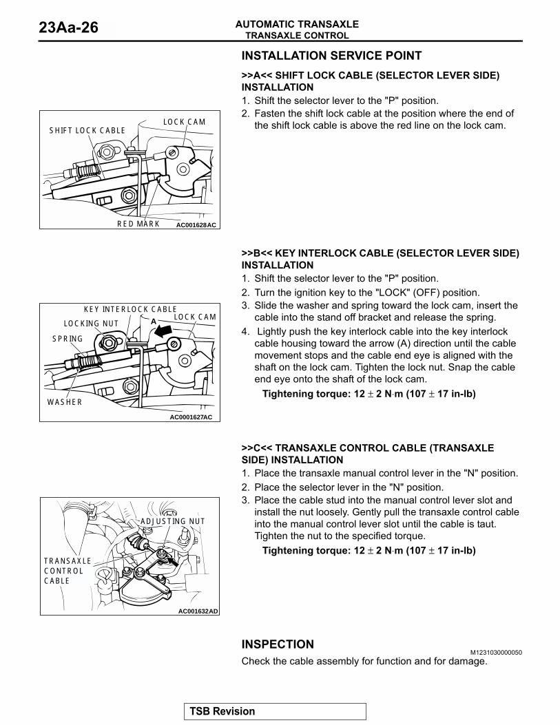
INSTALLATION SERVICE POINT.>>A<< SHIFT LOCK CABLE (SELECTOR LEVER SIDE) INSTALLATION1. Shift the selector lever to the "P" position.2. Fasten the shift lock cable at the position where the end of
the shift lock cable is above the red line on the lock cam.
.
>>B<< KEY INTERLOCK CABLE (SELECTOR LEVER SIDE) INSTALLATION1. Shift the selector lever to the "P" position.2. Turn the ignition key to the "LOCK" (OFF) position.3. Slide the washer and spring toward the lock cam, insert the
cable into the stand off bracket and release the spring.4. Lightly push the key interlock cable into the key interlock
cable housing toward the arrow (A) direction until the cable movement stops and the cable end eye is aligned with the shaft on the lock cam. Tighten the lock nut. Snap the cable end eye onto the shaft of the lock cam.
Tightening torque: 12 ± 2 N⋅m (107 ± 17 in-lb)
.
>>C<< TRANSAXLE CONTROL CABLE (TRANSAXLE SIDE) INSTALLATION1. Place the transaxle manual control lever in the "N" position.2. Place the selector lever in the "N" position.3. Place the cable stud into the manual control lever slot and
install the nut loosely. Gently pull the transaxle control cable into the manual control lever slot until the cable is taut. Tighten the nut to the specified torque.
Tightening torque: 12 ± 2 N⋅m (107 ± 17 in-lb)
INSPECTIONM1231030000050
Check the cable assembly for function and for damage.
AC001628ACRED MARK
SHIFT LOCK CABLELOCK CAM
AC0001627AC
SPRING
WASHER
LOCKING NUTLOCK CAM
KEY INTERLOCK CABLE
A
AC001632AD
TRANSAXLECONTROLCABLE
ADJUSTING NUT
TSB Revision

TRANSAXLE CONTROLAUTOMATIC TRANSAXLE 23Aa-27
DISASSEMBLY AND ASSEMBLYM1231006800233
AC100059AB
1
6
7
8
2
5
5
10114
9
3
2.2 ± 0.2 N·m20 ± 2 in-lb
12 ± 2 N·m107 ± 17 in-lb
4.9 ± 1.0 N·m44 ± 8 in-lb
REMOVAL STEPS1. SHIFT KNOB2. INDICATOR PANEL ASSEMBLY3. POSITION ILLUMINATION LIGHT
ASSEMBLY4. BOLT5. BUSHING
6. DETENTE SPRING7. LEVER SUB ASSEMBLY8. LOCK CAM9. LOCK CAM PIN10. COLLAR11. BASE BRACKET
REMOVAL STEPS (Continued)
TSB Revision

A/T KEY INTERLOCK AND SHIFT LOCK MECHANISMSAUTOMATIC TRANSAXLE23Aa-28
A/T KEY INTERLOCK AND SHIFT LOCK MECHANISMSREMOVAL AND INSTALLATION
M1232001200262
CAUTIONWhen removing and installing the transaxle control cable and shift lock cable unit, be careful not to hit the SRS-ECU.
REMOVAL SERVICE POINT.
<<A>> KEY INTERLOCK CABLE (SELECTOR LEVER SIDE) INSTALLATIONTurn the ignition key to the "LOCK" (OFF) position and pull out the key interlock cable.
Pre-removal and Post-installation Operation Floor Console Removal and Installation (Refer to GROUP 52A, Floor Console P.52A-7.)
AC100060
1
3
2
4
6
5
12 ± 2 N·m107 ± 17 in-lb
N
AB
KEY INTERLOCK CABLE REMOVAL STEPS
>>C<< 1. KEY INTERLOCK CABLE CONNECTION (SELECTOR LEVER SIDE)
• UNDER COVER (REFER TO GROUP 52A, INSTRUMENT PANEL ASSEMBLY P.52A-2.)
<<A>> >>B<< 2. KEY INTERLOCK CABLE CONNECTION (STEERING LOCK CYLINDER SIDE)
3. KEY INTERLOCK CABLE
SHIFT LOCK CABLE REMOVAL STEPS
>>A<< 4. SHIFT LOCK CABLE CONNECTION (SELECTOR LEVER SIDE)
• UNDER COVER (REFER TO GROUP 52A, INSTRUMENT PANEL ASSEMBLY P.52A-2.)
5. SHIFT LOCK CABLE CONNECTION (BRAKE PEDAL SIDE)
6. SHIFT LOCK CABLE
TSB Revision

A/T KEY INTERLOCK AND SHIFT LOCK MECHANISMSAUTOMATIC TRANSAXLE 23Aa-29
INSTALLATION SERVICE POINTS.
>>A<< SHIFT LOCK CABLE (SELECTOR LEVER SIDE) INSTALLATION1. Shift the selector lever in the "P" position.2. Fasten the shift lock cable at the position where the end of
the shift lock cable is positioned above the red marking on the lock cam.
3. Check the operation of the selector lever. (Refer to P.23Aa-22.)
.
>>B<< KEY INTERLOCK CABLE (STEERING LOCK CYLINDER SIDE) INSTALLATIONTurn the ignition key to the "LOCK" (OFF) position and install the key interlock cable..
>>C<< KEY INTERLOCK CABLE (SELECTOR LEVER SIDE) INSTALLATION1. Shift the selector lever to the "P" position.2. Turn the ignition key to the "LOCK" (OFF) position.3. Slide the washer and spring toward the lock cam, insert the
cable into the stand off bracket and release the spring.4. Lightly push the key interlock cable into the key interlock
cable housing toward the arrow (A) direction until the cable movement stops and the cable end eye is aligned with the shaft on the lock cam. Tighten the locking nut. Snap the cable end eye onto the shaft of the lock cam.
Tightening torque: 12 ± 2 N⋅m (107 ± 17 in-lb)5. Check the operation of the selector lever. (Refer to P.23Aa-
22.)
INSPECTIONM1231030000061
Check the cable assembly for function and for damage.
AC001628ACRED MARK
SHIFT LOCK CABLELOCK CAM
AC0001627AC
SPRING
WASHER
LOCKING NUTLOCK CAM
KEY INTERLOCK CABLE
A
TSB Revision

TRANSAXLE ASSEMBLYAUTOMATIC TRANSAXLE23Aa-30
TRANSAXLE ASSEMBLYREMOVAL AND INSTALLATION
M1231005700222
CAUTION*: Indicates parts which should be temporarily tightened, and then fully tightened after placing the vehicle horizontally and loading the full weight of the engine on the vehicle body.
Pre-removal and Post-installation Operation• Under Cover Removal and Installation• Engine Coolant Draining and Supplying (Refer to GROUP 14, On-vehicle Service P.14-22.)• A/T Fluid Draining and Supplying (Refer to GROUP 00, Maintenance Service − Automatic Transaxle P.00-43.)• Front Exhaust Pipe Removal and Installation (Refer to GROUP 15, Exhaust Pipe and Main Muffler P.15-9.)• Battery and Battery Tray Removal and Installation• Air Cleaner Assembly Removal and Installation (Refer to GROUP 15, Air Cleaner P.15-4.)• Selector Lever Operation Check <Post-installation Only> (Refer to P.23Aa-22.)• Speedometer Operation Check <Post-installation Only> (Refer to GROUP 54A, Combination Meter − On-vehicle Ser-
vice − Speedometer Check P.54A-39.)• Front Wheel Alignment Check and Adjustment <Post-installation Only> (Refer to GROUP 33, On-vehicle Service −
Front Wheel Alignment Check and Adjustment P.33A-6.)
AC104047AB
11
10
3
5
6
1
49 ± 5 N·m*36 ± 4 ft-lb*
81 ± 7 N·m*60 ± 5 ft-lb*
7
30 ± 3 N·m22 ± 2 ft-lb
48 ± 6 N·m36 ± 4 ft-lb
9
42
8
12 ± 2 N·m107 ± 17 in-lb
10
REMOVAL STEPS1. TRANSAXLE CONTROL CABLE
CONNECTION2. INPUT SHAFT SPEED SENSOR
CONNECTOR3. OUTPUT SHAFT SPEED
SENSOR CONNECTOR4. INHIBITOR SWITCH SENSOR
CONNECTOR5. A/T CONTROL SOLENOID VALVE
ASSEMBLY CONNECTOR
<<A>> 6. STARTER MOTOR7. TRANSAXLE OIL COOLER HOSE8. TRANSAXLE ASSEMBLY UPPER
PART COUPLING BOLTS9. TRANSAXLE MOUNT ASSEMBLY
>>D<< 10. TRANSAXLE MOUNT STOPPER11. TRANSAXLE MOUNT BRACKET
<<B>> • ENGINE ASSEMBLY SUPPORT
REMOVAL STEPS (Continued)
TSB Revision

TRANSAXLE ASSEMBLYAUTOMATIC TRANSAXLE 23Aa-31
CAUTION*: Indicates parts which should be temporarily tightened, and then fully tightened after placing the vehicle on the ground and loading the full weight of the engine on the vehicle body.
Required Special Tools:• MB990241: Axle shaft puller (MB990244: Puller
shaft, MB990242: Puller bar)• MB990767: End yoke holder• MB990998: Front hub remover and installer• MB991453: Engine Hanger Assembly
• MB991454: Engine Hanger Balancer (a part of MB991453 Engine Hanger Assembly)
• MB991895: Engine Hanger• MB991897: Ball Joint Remover• MZ203827: Engine Lifter
AC100062AC
18N
23
24
1317
1469 ± 10 N·m51 ± 7 ft-lb
52 ± 7 N·m*39 ± 5 ft-lb*
69 ± 10 N·m51 ± 7 ft-lb
N
N
25 ± 5 N·m19 ± 3 ft-lb
15
16
108 ± 10 N·m80 ± 7 ft-lb
N
12
N
19
49 ± 3 N·m36 ± 2 ft-lb
22
20
7.0 ± 1.0 N·m62 ± 9 in-lb
21
N
245 ± 29 N·m181 ± 21 ft-lb
REMOVAL STEPS• LIFTING UP OF THE VEHICLE12. SPEED SENSOR13. BRAKE HOSE CLAMP
>>C<< 14. STABILIZER BAR15. LOWER ARM
<<C>> 16. TIE ROD END<<D>> >>B<< 17. DRIVESHAFT <LH><<D>> >>B<< 18. DRIVESHAFT <RH>
19. CENTERMEMBER ASSEMBLY
20. FRONT ROLL STOPPER INSTALLATION BOLT
21. COVER• SUPPORT THE TRANSAXLE
WITH A TRANSAXLE JACK<<E>> 22. DRIVE PLATE BOLTS
23. TRANSAXLE ASSEMBLY LOWER PART COUPLING BOLTS
>>A<< 24. TRANSAXLE ASSEMBLY
REMOVAL STEPS (Continued)
TSB Revision

TRANSAXLE ASSEMBLYAUTOMATIC TRANSAXLE23Aa-32
REMOVAL SERVICE POINTS.<<A>> STARTER MOTOR REMOVALRemove the starter motor with the starter motor harness still connected, and secure it inside the engine compartment away from the engine..
<<B>> ENGINE ASSEMBLY SUPPORTING1. <Engine lifter MZ2073827 is used>
Set special tools MB991453 and MZ203827 to the vehicle to support the engine assembly.
2. <Engine hanger MB991895 is used>(1) Set special tool MB991895 to the strut assembly
mounting nuts (A and B) and the radiator support upper insulator mounting bolts (C and D), which are located in the engine compartment, as shown.
(2) Set special tool MB991454 to hold the engine/transaxle assembly.
.
AC100027ABMB991453
MZ203827
AC203705AB
A B
C D
AC104013AB
MB991895
MB991454
TSB Revision

TRANSAXLE ASSEMBLYAUTOMATIC TRANSAXLE 23Aa-33
<<C>> TIE ROD END/LOWER ARM DISCONNECTIONCAUTION
• Do not remove the nut from ball joint. Loosen it and use special tool MB991897 to avoid possible damage to ball joint threads.
• Hang special tool MB991897 with cord to prevent them from falling.
1. Install the special tool MB991897 as shown in the figure.
2. After turning the bolt and knob to adjust the insert arms of the special tool MB991897 in parallel, tighten the bolt by hand and confirm that the insert arms are parallel.NOTE: When adjusting the insert arms in parallel, turn the knob in the direction shown in the figure.
.
<<D>> DRIVESHAFT REMOVAL1. Use special tools MB990241 and MB990767 to push out the
driveshaft from the hub.
2. While pulling the lower side of the rotor toward you, remove the driveshaft from the hub.
AC106820AB
CORD
BOLT
MB991897NUT
BALL JOINT
AC106821
KNOB
PARALLEL
BOLT
GOOD
BAD AB
AC100139
MB990241
MB990767
AB
AC100140
TSB Revision

TRANSAXLE ASSEMBLYAUTOMATIC TRANSAXLE23Aa-34
CAUTION• Always use a lever when pulling out the driveshaft from
RJ assembly as tugging may damage the TJ assembly.• Care must be taken to ensure that the oil seal of the
transaxle is not damaged by the spline part of the drive-shaft.
• Do not apply the vehicle weight to the wheel bearing while loosening the driveshaft nut. If, however, the vehi-cle weight must be applied to the bearing (in order to move the vehicle), temporarily secure the wheel bear-ing by using special tool MB990998.
3. Insert a pry bar between the transaxle case and the driveshaft, and then pry the driveshaft from the transaxle.
.
<<E>> DRIVE PLATE COUPLING BOLTS REMOVAL1. Remove the drive plate coupling bolts while turning the
crank shaft.2. Pry the torque converter towards the transaxle side.
Remove the torque converter with the transaxle.
INSTALLATION SERVICE POINTS.
>>A<< TRANSAXLE ASSEMBLY INSTALLATIONInserting the torque converter into the transaxle oil pump so that the shown dimension is approximately 12.2 mm (0.48 inch). Install the transaxle assembly to the engine.
.
>>B<< DRIVESHAFT INSTALLATIONCAUTION
Care must be taken to ensure that the oil seal of the tran-saxle is not damaged by the spline part of the driveshaft..
AC001159
MB990998
TIGHTEN THENUT WITH THEBOLT SECURED AB
BOLT
AC100141AB
TRANSMISSION
TJ ASSEMBLY
PRY BAR
AC100110
APPROXMATELY12.2 mm (0.48 in)
AB
TSB Revision

SPECIFICATIONSAUTOMATIC TRANSAXLE 23Aa-35
>>C<< TRANSAXLE MOUNT STOPPER INSTALLATIONTighten the self-locking nut so that the stabilizer bar mounting bolt protrudes as shown.
Standard value: 22 ± 1.5 mm (0.87 ± 0.06 inch)
.
>>D<< TRANSAXLE MOUNT STOPPER INSTALLATIONInstall the transaxle mount stopper so that the arrow mark points as shown in the illustration.
SPECIFICATIONSFASTENER TIGHTENING SPECIFICATIONS
M1231012400171
AC006134AC
22 ± 1.5 mm (0.87 ± 0.06 in)
AC005916
TRANSAXLEMOUNT BRACKET
TRANSAXLE MOUNT STOPPER
ENGINE SIDE
AB
ITEM SPECIFICATIONKey interlock and shift lock mechanismsKey interlock cable attaching nut 12 ± 2 N⋅m (107 ± 17 in-lb)Shift lock cable attaching nut 12 ± 2 N⋅m (107 ± 17 in-lb)Transaxle assemblyAutomatic transmission fluid drain plug 32 ± 2 N⋅m (24 ± 1 ft-lb)Cover attaching bolt 7.0 ± 1.0 N⋅m (62 ± 9 in-lb)Center member attaching bolt 69 ± 10 N⋅m (51 ± 7 ft-lb)Drive plate bolt 49 ± 3 N⋅m (36 ± 2 ft-lb)Driveshaft connecting nut 245 ± 29 N⋅m (181 ± 21 ft-lb)Front roll stopper bracket retainer nut 52 ± 7 N⋅m (39 ± 5 ft-lb)Lower arm nut connecting nut 108 ± 10 N⋅m (80 ± 7 ft-lb)Starter motor attaching bolt 30 ± 3 N⋅m (22 ± 2 ft-lb)Tie rod end nut connecting bolt 25 ± 5 N⋅m (19 ± 3 ft-lb)Transaxle assembly upper part coupling bolt 48 ± 6 N⋅m (36 ± 4 ft-lb)Transaxle control cable connecting nut 12 ± 2 N⋅m (107 ± 17 in-lb)Transaxle mount bracket attaching nut 49 ± 5 N⋅m (36 ± 4 ft-lb)Transaxle mount stopper attaching nut 81 ± 7 N⋅m (60 ± 5 ft-lb)
TSB Revision

SPECIFICATIONSAUTOMATIC TRANSAXLE23Aa-36
SERVICE SPECIFICATIONSM1231000300177
LUBRICANTM1231000400237
Transaxle controlBolt attaching nut 12 ± 2 N⋅m (107 ± 17 in-lb)Key inter lock cable attaching nut 12 ± 2 N⋅m (107 ± 17 in-lb)Lock cam pin attaching nut 4.9 ± 1.0 N⋅m (44 ± 8 in-lb)Park/Neutral position switch mounting bolt 11 ± 1 N⋅m (96 ± 8 in-lb)Shift knob attaching screw 2.2 ± 0.2 N⋅m (20 ± 2 in-lb)Selector lever assembly attaching bolt 12 ± 2 N⋅m (102 ± 22 in-lb)Shift lock cable attaching nut 12 ± 2 N⋅m (107 ± 17 in-lb)Transaxle control cable attaching bolt 12 ± 2 N⋅m (107 ± 17 in-lb)Transaxle control cable connecting nut 12 ± 2 N⋅m (107 ± 17 in-lb)
ITEM SPECIFICATION
ITEM STANDARD VALUEA/T fluid temperature sensor kΩ at 0°C (32°F) 16.7 − 20.5
at 20°C (68°F) 7.3 − 8.9at 40°C (104°F) 3.4 − 4.2at 60°C (140°F) 1.9 − 2.2at 80°C (176°F) 1.0 − 1.2at 100°C (212°F) 0.57 − 0.69
Line pressure MPa (psi) 1.01 − 1.05 (147 − 152)Protruding length of stabilizer bar mounting bolt mm (in) 22 ± 1.5 (0.87 ± 0.06)Resistance of torque converter clutch control solenoid valve coil [at 20°C (68°F)] Ω
2.7 − 3.4
Resistance of low-reverse solenoid valve coil [at 20°C (68°F)] Ω 2.7 − 3.4Resistance of overdrive solenoid valve coil [at 20°C (68°F)] Ω 2.7 − 3.4Resistance of second solenoid valve coil [at 20°C (68°F)] Ω 2.7 − 3.4Resistance of underdrive solenoid valve coil [at 20°C (68°F)] Ω 2.7 − 3.4Stall speed r/min 2,100 − 2,600
ITEM SPECIFIED LUBRICANT QUANTITY
A/T fluid dm3 (qt) DIAMOND ATF SP III or equivalent 7.7 (8.1)
TSB Revision