Group 2 - hynedi.free.frhynedi.free.fr/doc_technique/pompe_sauer_groupe2.pdf · SAUER-SUNDSTRAND...
48
Gear Pumps Technical Information Group 2
Transcript of Group 2 - hynedi.free.frhynedi.free.fr/doc_technique/pompe_sauer_groupe2.pdf · SAUER-SUNDSTRAND...

Gear Pumps
Technical Information
Group 2

Gear Pumps Group 2
2
Copyright 1988, 1989, 1990, 1991, 1994, 1997, 1998 Sauer-Sundstrand Company.All rights reserved. Contents subject to change. All trademarks property of their respective owners. Printed in U.S.A. 0998H
Group 2 Family of Gear Pumps
SAUER-SUNDSTRAND High performance gearpumps are fixed displacement pumps which consistof the pump housing, drive gear, driven gear, DUbushings, rear cover and front flange, shaft seal, andinner / outer seals, as shown in the section drawing onpage 4. The pressure balanced design of the pumpsprovides high efficiency for the entire series.
The standard SNP 2 pumps are offered throughoutthe given range of displacements. There are also twospecial versions, the SHP 2 and the SKP 2. The SHPuses longer journal bearings to achieve a higherpressure capability in the larger displacements. TheSKP is designed to accommodate an 11 tooth splinedshaft for higher torque applications.
• Large Displacement Range from 4 to 25 cm 3
• High Performance at Low Cost
• Patented, Efficient Pressure Balanced Design
• Proven Reliability and Performance
• Optimum Product Configurations
• Full Range of Auxiliary Features
• Compact, Lightweight
• Modular Product Design
• Quiet Operation
• Worldwide Sales and Service

Gear Pumps Group 2
3
ContentsGroup 2 Family of Gear Pumps ....................................................................................................................... 2Contents .......................................................................................................................................................... 3Group 2 Pump Features .................................................................................................................................. 4Typical Gear Pump Circuit ............................................................................................................................... 5Technical Data ................................................................................................................................................. 6
Hardware Specifications ............................................................................................................... 6System Specifications .................................................................................................................. 7
Model Code ..................................................................................................................................................... 8Standard Formulae for Determination of Nominal Pump Size ........................................................................ 10Definition and Explanation of Technical Terms ................................................................................................11System Requirements ................................................................................................................................... 12
Hydraulic Fluid ........................................................................................................................................... 12Temperature and Viscosity ......................................................................................................................... 12Fluids and Filtration .................................................................................................................................... 13Reservoir .................................................................................................................................................... 13Inlet Design ................................................................................................................................................ 14Line Sizing .................................................................................................................................................. 14Pump Drive ................................................................................................................................................ 15
Pump Drive Data Form ........................................................................................................................... 16Pump Life ...................................................................................................................................................... 17Sound Levels ................................................................................................................................................. 18Pump Performance........................................................................................................................................ 19Product Options ............................................................................................................................................. 23
Shaft Options ............................................................................................................................................. 23Shaft availability and torque capacity .......................................................................................... 23
Mounting flanges ........................................................................................................................................ 24Available Mounting Flanges ..................................................................................................... ... 24
Nonstandard Port Configurations ............................................................................................................... 25Available Porting Options ........................................................................................................... 25
Integral Priority Flow Divider Valve ............................................................................................................. 26Valve operation and performance ............................................................................................................ 27Order Codes for Integral Priority Flow Divider ......................................................................................... 32
Order Codes ............................................................................................................................... 32Variant Codes ............................................................................................................................. 32
Integral Relief Valve (SNE 2 / SNI 2) .......................................................................................................... 33Variant Codes for Ordering Integral Relief Valve ......................................................................... 33
Outrigger Bearing Assembly ....................................................................................................................... 34Available Configurations ............................................................................................................. 34
Auxiliary Mounting Pads ............................................................................................................................. 35Auxiliary Mounting Pad Specifications ........................................................................................ 35
Product Dimensional Information ................................................................................................................... 36SC01 / CI01 / CO01 ................................................................................................................................... 36SC02 / CO02 .............................................................................................................................................. 37FR03 .......................................................................................................................................................... 38SC04 / SC05 / CO04 / CO05 ...................................................................................................................... 39SC06 / CI06 ................................................................................................................................................ 40CO09 .......................................................................................................................................................... 41CO09 (variant BBM) ................................................................................................................................... 42CO0B ......................................................................................................................................................... 43Nonstandard Port Configurations ............................................................................................................... 44Integral Priority Flow Divider Cover and Integral Relief Valve Cover .......................................................... 45Outrigger Bearings ..................................................................................................................................... 46Auxiliary Mounting Pad ............................................................................................................................... 47

Gear Pumps Group 2
4
Pressure compensated bearingsmade of anti-friction alloy.
New sealing system designfor high pressure andleakage prevention.
Extruded aluminum alloy body forhigh pressure, with flanged orthreaded type ports compatible withthe standards of the market.
Shaft seal with built instiffener and dust lip.
Various shaft options including:tapered, splined, parallel, and tang.
PTFE / bronze based bushings forlong life and high performance.
Full range of mountingflanges, meeting the stan-dards of the market.
High quality case hardenedsteel gears with superiorsurface finishing.
Group 2 Pump Features
P101 000

Gear Pumps Group 2
5
Gear Pump
Filter
Wax CapsuleThermal Sensor
Gear Motor
Reservoir
SystemPressureControlValve
Pump InletPump OutputControlled FlowReturn FlowPilot Flow
Typical Gear Pump Circuit
This circuit shows an SNP2 gear pump driving anSNM2 gear motor through a system pressure con-trol valve . The system pressure control valve regu-lates motor speed based on input from the waxcapsule thermal sensor . Discharge from the gear
motor is then returned to the reservoir . Oil in thiscircuit is cleaned by a pressure filter placed betweenthe gear pump and the system pressure control valve.
P101 001P101 034

Gear Pumps Group 2
6
Technical DataSpecifications for Group 2 pumps are listed on thesetwo pages.
Hardware Specifications
ledoMpmuP 4 6 8 11 41 71 91 22 52
tnemecalpsiD mc 3 ver/ni[ 3 ]ver/
9.3]42.0[
0.6]73.0[
4.8]15.0[
8.01]66.0[
4.41]88.0[
8.61]20.1[
2.91]71.1[
8.22]93.1[
2.52]45.1[
PNS
erusserPkaeP rab]isp[
082]0604[
082]0604[
082]0604[
082]0604[
082]0604[
082]0604[
032]5333[
002]0092[
571]8352[
erusserPdetaR rab]isp[
052]5263[
052]5263[
052]5263[
052]5263[
052]5263[
052]5263[
012]5403[
081]0162[
061]0232[
rab001-0tadeepSmuminiM nim 1-
)mpr( 006 006 006 005 005 005 005 005 005
rab081-001tadeepSmuminiM nim 1-
)mpr( 0021 0021 0001 008 057 057 007 007 007
tadeepSmuminiMerusserpdetarotrab081
nim 1-
)mpr( 0041 0041 0041 0021 0001 0001 0001 008 008
eepSmumixaM d nim 1-
)mpr( 0004 0004 0004 0004 0053 0003 0003 0003 0003
PKS
erusserPkaeP rab]isp[
082]0604[
082]0604[
082]0604[
082]0604[
082]0604[
082]0604[
062]0773[
032]5333[
002]0092[
erusserPdetaR rab]isp[
052]5263[
052]5263[
052]5263[
052]5263[
052]5263[
052]5263[
042]0843[
012]5403[
091]5572[
rab001-0tadeepSmuminiM nim 1-
)mpr( 006 006 006 005 005 005 005 005 005
rab081-001tadeepSmuminiM nim 1-
)mpr( 0021 0021 0001 008 057 057 007 007 007
tadeepSmuminiMerusserpdetarotrab081
nim 1-
)mpr( 0041 0041 0041 0021 0001 0001 0001 008 008
eepSmumixaM d nim 1-
)mpr( 0004 0004 0004 0004 0053 0003 0003 0003 0003
PHS
erusserPkaeP rab]isp[
062]0773[
032]5333[
002]0092[
erusserPdetaR rab]isp[
042]0843[
012]5403[
091]5572[
rab001-0tadeepSmuminiM nim 1-
)mpr( 006 006 006
rab081-001tadeepSmuminiM nim 1-
)mpr( 008 008 008
tadeepSmuminiMerusserpdetarotrab081
nim 1-
)mpr( 0001 0001 0001
eepSmumixaM d nim 1-
)mpr( 0003 0003 0003
LLA .spmupderugifnocdradnatsrofseulavnaemtneserperwolebatadehT
thgieW gk]bl[
3.2]1.5[
4.2]3.5[
5.2]5.5[
7.2]8.5[
9.2]3.6[
0.3]5.6[
1.3]7.6[
2.3]0.7[
3.3]3.7[
foaitrenIfotnemoMstnenopmocgnitator
01x 6- mgk 2
01x[ 6- tffbl 2]6.02]984[
7.52]016[
5.13]747[
3.73]588[
9.54]9801[
7.15]7221[
5.75]4631[
2.66]1751[
0.27]9071[
tawolFlacitereohTdeepSmumixaM
nim/l]nim/lagSU[
6.51]21.4[
0.42]43.6[
6.33]78.8[
2.34]4.11[
4.05]3.31[
4.05]3.31[
6.75]2.51[
4.86]0.81[
6.57]0.02[
T101 000E
For definition and explanation of the various terms,see page 11.

Gear Pumps Group 2
7
System Specifications
etulosbarab-erusserPtelnI
egnaRdednemmoceR 0.3ot8.0
)tratsdloc(muminiM 6.0
mm-ytisocsiVdiulF 2 ]SUS[)tSc(s/
muminiM ]06[01
egnaRdednemmoceR ]092ot66[06ot21
)tratsdloc(mumixaM ]0057[0061
]F°[C°-erutarepmeT
)tratsdloc(tnettimretnI ]4-[02-
suounitnoCmumixaM ]671[08
)tnettimretni(kaeP ]491[09
dnaleveLssenilnaelCdiulF bx oitaR
leveLssenilnaelCdiulF)6044OSIrep(
rettebro31/81ssalC
βx oitaR)noitartliFnoitcuS(
β 54-53 dna57= β 01 2=
βx roerusserP(oitaR)noitartliFnruteR
β 01 57=
telnIdednemmocceReziSneercS
mµ521-001
T101 001E
T101 002E
T101 003E
T101 004E

Gear Pumps Group 2
8
TypeSNP 2 = Standard Gear PumpSKP 2 = High Torque Gear PumpSHP 2 = High Pressure Gear PumpSNI 2 = Gear Pump with Internal Drain Relief ValveSNE 2 = Gear Pump with External Drain Relief Valve
Valve (omit when not used)C = Priority Flow Divider with Pilot Relief ValveL = Priority Flow Divider with Pilot Relief Valve and Static Load SensingN = Priority Flow Divider with Pilot Relief Valve and Dynamic Load SensingQ = Priority Flow Divider with Full Flow Relief ValveR = Priority Flow Divider with Full Flow Relief Valve and Static Load SensingV = Priority Flow Divider with Full Flow Relief Valve and Dynamic Load Sensing
Valve Port Position (omit when not used)S = Side Ports (standard SAE O-Ring Boss, 9/16" - Priority, 7/8" - Non Priority)R = Rear Ports (standard SAE O-Ring Boss, 9/16" - Priority, 7/8" - Non Priority)
Displacementcm3/rev / [(in3/rev]
4 = 3.9 / [0.24]6 = 6.0 / [0.37]8 = 8.4 / [0.51]11 = 10.8 / [0.66]14 = 14.4 / [0.88]17 = 16.8 / [1.02]19 = 19.2 / [1.17]22 = 22.8 / [1.39]25 = 25.2 / [1.54]
Direction of RotationD = Right (Clockwise)S = Left (Anti-clockwise)
Input Shaft / Mounting Flange / Port ConfigurationCO Tapered shafts, 1:5 or 1:8
CO01 = 1:8 tapered shaft / European four bolt flange / European flanged portsCO02 = 1:5 tapered shaft / German four bolt PTO flange / German standard portsCO04 = 1:5 tapered shaft / German two bolt PTO flange (Deutz) / German standard portsCO05 = 1:5 tapered shaft / German two bolt PTO flange (Deutz) / German standard portsCO09 = 1:8 tapered shaft / Perkins 4.236 timing case flange / European flanged portsCO09 = (variant BBM) 1:8 tapered shaft / Perkins 900 series flange / German standard portsCO0B = 1:8 tapered shaft / Perkins 1000 series left side PTO flange / European flanged portsCO91 = (variant LBD) 1:8 tapered shaft / European four bolt flange / European flanged ports / equipped with outrigger bearingCO94 = 1:5 tapered shaft / German two bolt PTO flange (Deutz) / German standard ports / equipped with outrigger bearing
CI Parallel shafts, 15mm or 15.875mmCI01 = 15mm [.591 in] parallel shaft / European four bolt flange / European flanged portsCI06 = 15.875mm [.625 in] parallel shaft / SAE "A" flange / SAE O-ring boss portsCI96 = (variant LEP) 19.05mm [.750 in] parallel shaft / SAE "A" flange / SAE O-ring boss ports / equipped with outrigger bearing
SC Splined shafts, DIN B17x14, SAE 9T 16/32p, or SAE 11T 16/32p (SKP 2 only)SC01 = DIN splined shaft / European four bolt flange / European flanged portsSC02 = DIN splined shaft / German four bolt PTO flange / German standard portsSC04 = DIN splined shaft / German two bolt PTO flange (Deutz) / German standard portsSC05 = DIN splined shaft / German two bolt PTO flange (Deutz) / German standard portsSC06 = SAE splined shaft / SAE A flange / SAE O-ring boss portsSC36 = SAE splined shaft / SAE A flange plus SAE A auxiliary mounting pad / SAE O-ring boss ports
FR Sauer-Sundstrand tang shaftFR03 = Sauer-Sundstrand tang shaft / flanged for multiple configuration / German standard ports
Model Code
/H L M N P R SA B C D E F

Gear Pumps Group 2
9
/H L M N P R SA B C D E F
Variant Code (Three letter code describes valve settings or other variants to standard configuration)BBM = Variation on 09 flange to accommodate Perkins 900 series engine mountingLEP = Variant on standard straight shaft used with CI96 outrigger bearing option.LBD = Variant on standard tapered shaft used on CO91 outrigger bearing option.U** Integral flow divider
Pressure setting [bar] / (psi)L = [60] (870)M = [70] (1015)N = [80] (1160)O = [90] (1305)P = [100] (1450)Q = [110] (1595)R = [120] (1740)S = [130] (1885)
Controlled flow [l/min] / (US gal/min)M = [8] (2.11)F = [10] (2.64)N = [12] (3.17)O = [14] (3.70)P = [16] (4.23)
V** Integral relief valvePressure setting [bar] / (psi)
A = No settingB = No valveC = [18] (261)E = [30] (435)F = [35] (508)G = [40] (580)K = [50] (725)L = [60] (870)M = [70] (1015)N = [80] (1160)O = [90] (1305)
Pump speed for relief valve setting (min-1 (rpm))A = Not definedC = 500E = 1000F = 1250G = 1500K = 2000I = 2250L = 2500M = 2800N = 3000
Version (Value representing a change to the initial project). = Initial project1..9 A..Z = Reserved to
Port Type (If other than standard). = Standard port for the flange type specifiedB = Flanged port with threaded holes in "X" pattern (German standard ports), centered on the bodyC = Flanged port with threaded holes in "+" pattern (European Standard)E = Threaded SAE o-ring boss portF = Threaded Gas port (BSP)G = Flanged port with threaded holes in "X" pattern (German standard ports), offset from center of body
T = [140] (2030)C = [150] (2175)U = [160] (2320)D = [170] (2465)V = [180] (2611)E = [190] (2755)X = [200] (2901)
J = [18] (4.75)Q = [20] (5.28)K = [22] (5.80)R = [24] (6.34)I = [26] (6.86)
P = [100] (1450)Q = [110] (1595)R = [120] (1740)S = [130] (1885)T = [140] (2030)U = [160] (2320)V = [170] (2465)X = [190] (2755)Y = [210] (3045)Z = [230] (3335)

Gear Pumps Group 2
10
Standard Formulae for Determination of Nominal Pump Size
The formulas below will aid in determining the nominalpump size for a specific application.
Metric System
Output Flow Q =Vg • n • v
1 000
η(l/min)
Input Torque M =Vg • p
20 • • m
∆π η
(Nm)
Input Power P = M • n •30 000
π (kW)Q • p
600 • t
∆η
=
ηt = η ηv • m = Overall efficiency
ηm = Mechanical efficiency
ηv = Volumetric efficiency
n = Speed (min-1 [rpm])
∆p = po- pi (bar) (system pressure)
pi = Inlet Pressure (bar)
po = Outlet Pressure (bar)
Vg = Displacement per revolution (cm3)
Inch System
Output Flow Q =Vg • n • v
231
η(US gal/min)
Input Torque M =Vg • p
2 • • m
∆π η
(lbf • in)
Input Power P = M • n •396 000
π (HP)Q • p
1714 • t
∆η
=
ηt = η ηv • m = Overall efficiency
ηm = Mechanical efficiency
ηv = Volumetric efficiency
n = Speed (min-1 [rpm])
∆p = po- pi (psi) (system pressure)
pi = Inlet Pressure (psi)
po = Outlet Pressure (psi)
Vg = Displacement per revolution (in3)
S101 000ES101 001E
S101 002ES101 003E

Gear Pumps Group 2
11
Definition and Explanation of Technical Terms
Maximum speed is the speed limit recommendedwhen operating at rated pressure. It is the highestspeed at which normal life can be expected.
Minimum Speed is the lower limit of operating speed.It is the lowest speed at which normal bearing life canbe expected. It is important to note that the minimumspeed increases as operating pressure increases.When operating under higher pressures, a higherminimum speed must be maintained (see graph be-low).
OperatingEnvelope
Rated
P2
P1Pre
ssur
e
00 N1 N2
SpeedMAXN3
Where:N1 = Minimum speed at 100 barN
2 = Minimum speed at 180 bar
N3 = Minimum speed at rated pressure
System pressure is the differential of pressurebetween the outlet and inlet ports. It is a dominantoperating variable affecting hydraulic unit life. Highsystem pressure, which results from high load, re-duces expected life. System pressure must remain ator below rated pressure during normal operation toachieve expected life.
Rated pressure is the average, regularly occurringoperating pressure that should yield satisfactory prod-uct life. It can be determined by the maximum ma-chine load demand. For all systems the load shouldmove below this pressure.
Peak pressure is the highest intermittent pressureallowed, and is determined by the relief valve overshoot (reaction time). Peak pressure is assumed tooccur for less than 100 ms in duration.
Inlet pressure must be controlled in order to achieveexpected life and performance. A continuous inletpressure less than those shown in the table belowwould indicate inadequate inlet design or a restrictedinlet screen. Lower inlet pressures during cold startshould be expected, but should improve quickly asthe fluid warms.
etulosbarab-erusserPtelnI
egnaRdednemmoceR 0.3ot8.0
)tratsdloc(muminiM 6.0
T101 005E
T101 006E
T101 001E

Gear Pumps Group 2
12
Hydraulic Fluid
System Requirements
Ratings and data for Group 2 gear pumps are based onoperation with premium hydraulic fluids containing oxi-dation, rust, and foam inhibitors. These fluids mustpossess good thermal and hydrolytic stability to preventwear, erosion, and corrosion of internal components.
These include:
• Hydraulic fluids per DIN 51524, part 2 (HLP)and part 3 (HVLP)
• API CD engine oils per SAE J183
• M2C33F or G automatic transmission fluids
• Dexron II, IIE, and III meeting Allison C3 orCaterpillar TO-2
• Certain agricultural tractor fluids
For more information on fluid selection, see Sauer-Sundstrand publication BLN-9887 or 697581. Forinformation relating to biodegradable fluids, see Sauer-Sundstrand publication ATI-E 9101.
Never mix hydraulic fluids.
Temperature and Viscosity
Temperature and viscosity requirements must beconcurrently satisfied. The data shown assumes pe-troleum / mineral based fluids. The high temperaturelimits apply at the inlet port to the pump. The pumpshould generally be run at or below the maximumcontinuous temperature . The peak temperature isbased on material properties and should never beexceeded. Cold oil will generally not affect the dura-bility of the pump components, but it may affect theability to flow oil and transmit power; therefore tem-peratures should remain 16°C (30°F) above the pourpoint of the hydraulic fluid. The intermittent (mini-mum) temperature relates to the physical propertiesof component materials. For maximum unit efficiencyand bearing life the fluid viscosity should remain in therecommended viscosity range . The minimumviscosity should be encountered only during briefoccasions of maximum ambient temperature andsevere duty cycle operation. The maximum viscos-ity should be encountered only at cold start. Duringthis condition speeds should be limited until the sys-tem warms up. Heat exchangers should be sized tokeep the fluid within these limits. Testing is recom-mended to verify that these temperature and viscositylimits are not exceeded.
mm-ytisocsiVdiulF 2 ]SUS[)tSc(s/
muminiM ]06[01
egnaRdednemmoceR ]092ot66[06ot21
)tratsdloc(mumixaM ]0057[0061
]F°[C°-erutarepmeT
)tratsdloc(tnettimretnI ]4-[02-
suounitnoCmumixaM ]671[08
)tnettimretni(kaeP ]491[09
T101 002E
T101 003E

Gear Pumps Group 2
13
Fluids and Filtration
The function of the reservoir is to provide clean fluid,dissipate heat, remove entrained air, and allow for fluidvolume changes associated with fluid expansion andcylinder differential volumes.
The reservoir should be designed to accommodatemaximum volume changes during all system operatingmodes and to promote deaeration of the fluid as itpasses through the tank. The design should accommo-date a fluid dwell time between 60 and 180 seconds toallow entrained air to escape.
Minimum reservoir capacity depends on the volumeneeded to cool the oil, hold the oil from all retractedcylinders, and allow expansion due to temperaturechanges. Normally, a fluid volume of 1 to 3 times thepump output flow (per minute) is satisfactory. Theminimum reservoir capacity is recommended to be125% of the fluid volume.
To prevent premature wear, it is imperative that onlyclean fluid enter the pump and hydraulic circuit. A filtercapable of controlling the fluid cleanliness to Class 18/13 per ISO 4406 or better under normal operatingconditions is recommended.
The filter may be located on the pump outlet (pressurefiltration), inlet (suction filtration), or the reservoirreturn (return line filtration).
The selection of a filter depends on a number offactors including the contaminant ingression rate, thegeneration of contaminants in the system, the re-quired fluid cleanliness, and the desired maintenanceinterval. Contaminant ingression rate is determined(among other things) by the type of actuators used inthe system. Hydraulic cylinders normally cause higherlevels of contamination to enter the system.
dnaleveLssenilnaelCdiulF bx oitaR
leveLssenilnaelCdiulF)6044OSIrep(
rettebro31/81ssalC
βx oitaR)noitartliFnoitcuS(
β 54-53 dna57= β 01 2=
βx roerusserP(oitaR)noitartliFnruteR
β 01 57=
telnIdednemmocceReziSneercS
mµ521-001
Filters are selected to meet these requirements usingrating parameters of efficiency and capacity. Filterefficiency may be measured with a Beta ratio1 (β
X). For
suction filtration, with controlled reservoir ingression, afilter with β
35-45 = 75 (and β
10 = 2) or better has been
found to be satisfactory. For return or pressure filtra-tion, filters with an efficiency of β
10 = 75 are typically
required.
Since each system is unique, the filtration require-ments for that system will be unique and must bedetermined by test in each case. Filtration systemacceptability should be judged by monitoring of proto-types, evaluation of components, and performancethroughout the test program.
See Sauer-Sundstrand publications BLN-9887[697581] and ATI-E 9201 for more information.
(1) Filter β x ratio is a measure of filter efficiency defined by ISO4572. It is defined as the ratio of the number of particles greaterthan a given diameter (“x” in microns) upstream of the filter tothe number of these particles downstream of the filter.
Reservoir
The suction line should be located above the bottom ofthe reservoir to take advantage of gravity separationand prevent large foreign particles from entering theline. A 100 -125 µm screen covering the suction line isrecommended. To minimize vacuum at the pumpinlet, it is recommended that the pump be locatedbelow the lowest expected fluid level.
The return line should be positioned to allow dis-charge below the lowest fluid level, and directedinto the interior of the reservoir for maximum dwelland efficient deaeration.
A baffle (or baffles) between the return line andsuction line will promote deaeration and reducesurging of the fluid.
T101 004E

Gear Pumps Group 2
14
The choice of piping size and installation shouldalways be consistent with maintaining minimum fluidvelocity. This will reduce system noise, pressuredrops and overheating, thereby maximizing systemlife and maximum performance. Inlet piping should bedesigned to maintain continuous pump inlet pres-sures above 0.8 bar absolute during normal opera-tion. The inlet line velocity should not exceed 2.5 m/s [8.2 ft/s]. Pump outlet line velocity should not ex-ceed 5 m/s [16.4 ft/s]. System return lines should belimited to 3 m/s [9.8 ft/s].
Inlet Design
Hydraulic oil used in the majority of systems containsabout 10% dissolved air by volume. Under conditionsof high inlet vacuum, bubbles are released from theoil. These bubbles collapse when subjected to pres-sure, which results in cavitation which causes erosionof the adjacent material. Because of this, the greaterthe air content within the oil, and the greater thevacuum in the inlet line, the more severe will be theresultant erosion.
The main causes of over-aeration are air leaks on theinlet side of the pump, and flow line restrictions. Thesemay include inadequate pipe sizes, sharp bends, orelbow fittings causing a reduction of flow line crosssectional area. Providing pump inlet vacuum andrated speed requirements are maintained, and reser-voir size and location are adequate, no cavitationproblems should occur.
Line Sizing

Gear Pumps Group 2
15
Pump Drive
With a choice between tapered, splined, or parallelshafts, Sauer-Sundstrand gear pumps are suitablefor a wide range of direct and indirect drive applica-tions. Typically these applications use a plug-in, belt,or gear to drive the pump input shaft. Group 2 pumpsare designed with bearings that can accept someincidental external radial and thrust loads. However,any amount of external load may reduce the expectedbearing life. An outrigger bearing is available toaccommodate these loads and is shown on page 32.
For in-line drive applications, it is recommended thata three piece coupling be used to minimize radial orthrust shaft loads. Plug-in drives, acceptable onlywith spline shaft configurations, can impose severeradial loads on the pump shaft when the mating splineis rigidly supported. Increased spline clearance doesnot alleviate this condition. The use of plug in drivesis permissible providing that the concentricity be-tween the mating spline and pilot diameter is within0.1 mm [.004 in]. The drive should be lubricated byflooding with oil.
The allowable radial shaft loads are a function of theload position, the load orientation, and the operatingpressure of the hydraulic pump. All external shaftloads will have an effect on bearing life and may affectpump performance. In applications where externalshaft loads cannot be avoided, the impact on thepump can be minimized by optimizing the orientationand magnitude of the load. A tapered input shaft isrecommended for applications where radial shaftloads are present. Spline shafts are not recom-mended for belt or gear drive applications. For beltdrive applications, a spring loaded belt tension deviceis recommended to avoid excessive belt tension.
Thrust (axial) loads in either direction should beavoided. If continuously applied external radial orthrust loads are known to occur, contact Sauer-Sundstrand for evaluation.
Contact your Sauer-Sundstrand representative for assis-tance when applying pumps with radial or thrust loads.
Pilot Cavity
Mating Spline
© Ø 0.1 [.004]
P101 002E
Gear Pumps Group 2
16
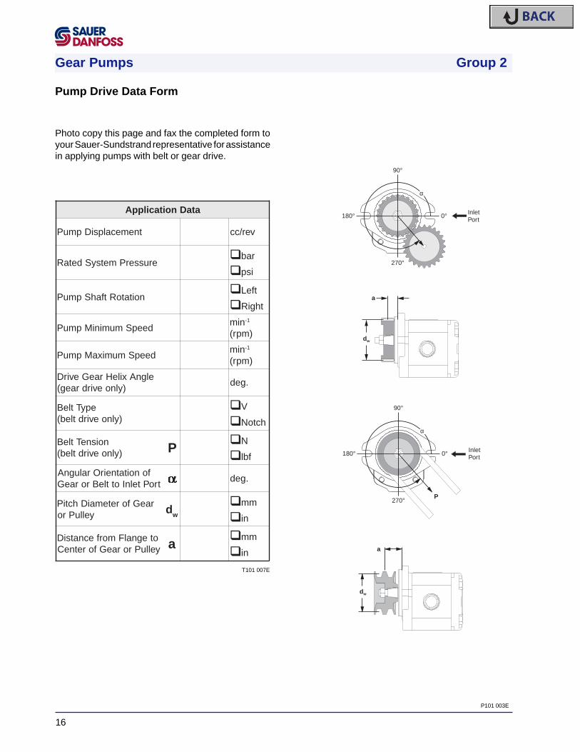
Photo copy this page and fax the completed form toyour Sauer-Sundstrand representative for assistancein applying pumps with belt or gear drive.
ataDnoitacilppA
tnemecalpsiDpmuP ver/cc
erusserPmetsySdetaRq rab
q isp
noitatoRtfahSpmuPq tfeL
q thgiR
deepSmuminiMpmuPnim 1-
)mpr(
deepSmumixaMpmuPnim 1-
)mpr(
elgnAxileHraeGevirD)ylnoevirdraeg(
.ged
epyTtleB)ylnoevirdtleb(
qV
q hctoN
noisneTtleB)ylnoevirdtleb( P
qN
q fbl
fonoitatneirOralugnAtroPtelnIottleBroraeG a .ged
raeGforetemaiDhctiPyelluPro dw
q mm
qni
otegnalFmorfecnatsiDyelluProraeGforetneC a
q mm
qni
90°
180° 0°
270°
α
InletPort
90°
180° 0°
270°
α
InletPort
P
dw
a
dw
a
T101 007E
P101 003E
Pump Drive Data Form

Gear Pumps Group 2
17
Pump Life
All Sauer-Sundstrand gear pumps utilize hydrody-namic journal bearings which have an oil film main-tained between the gear / shaft and bearing surfacesat all times. If this oil film is sufficiently sustainedthrough proper system maintenance and operatingwithin recommended limits, long life can be expected.
NOTE: A B10
type life expectancy number is generallyassociated with rolling element bearings and does notexist for hydrodynamic bearings.
Pump life is defined as the life expectancy of the
hydraulic components and is a function of speed,system pressure, and other system parameters suchas oil cleanliness. High pressure, which results fromhigh load, reduces expected life in a manner similar tomany mechanical assemblies such as engines andgear boxes. When reviewing an application, it isdesirable to have projected machine duty cycle datawhich includes percentages of time at various loadsand speeds.
Sauer-Sundstrand gear pumps have an expected lifeof over one million cycles operating at rated pressureand a speed of 3000 min-1 (rpm).
Prototype testing programs to verify operating pa-rameters and their impact on life expectancy arestrongly recommended prior to finalizing any systemdesign.

Gear Pumps Group 2
18
Sound LevelsFluid power systems are inherent generators of noise.As with many high power density devices, noise is anunwanted side affect. However, there are manytechniques available to minimize noise from fluidpower systems. To apply these methods effectively,it is necessary to understand how the noise is gener-ated and how it reaches the listener.
The noise energy can be transmitted away from itssource as either fluid borne noise (pressure ripple) oras structure borne noise.
Pressure ripple is the result of the number of pump-ing elements (gear teeth) delivering oil to the outletand the pump’s ability to gradually change the volumeof each pumping element from low to high pressure.In addition, the pressure ripple is affected by thecompressibility of the oil as each pumping elementdischarges into the outlet of the pump. Pressurepulsations will travel along the hydraulic lines at thespeed of sound (about 1400m/s in oil) until affected bya change in the system such as an elbow fitting. Thusthe pressure pulsation amplitude varies with overallline length and position.
Structure borne noise may be transmitted whereverthe pump casing is connected to the rest of thesystem.
The manner in which one circuit component respondsto excitation will depend on its size, form, and mannerin which it is mounted or supported. Because of thisexcitation, a system line may actually have a greaternoise level than the pump. To reduce this excitation,use flexible hoses in place of steel plumbing. If steelplumbing must be used, clamping of lines is recom-mended. To minimize other structure borne noise,use flexible (rubber) mounts.
The accompanying graph shows typical sound pres-sure levels for SNP2 pumps (with SAE A flange, andspline shaft in plug in drive) measured in dB(A) at 1meter [3.28 ft.] from the unit in a semi-anechoicchamber. Anechoic levels can be estimated bysubtracting 3 dB(A) from these values.
Contact your Sauer-Sundstrand representative forassistance with system noise control.
0 5 10 15 20 25 30
80
75
70
65
60
55
50
Displacement (cc/rev)
Sou
nd P
ress
ure
(dB
A a
t 1m
[3.3
ft])
1800 rpm, 175 bar [2538 psi]3000 rpm, 175 bar [2538 psi]1800 rpm, 250 bar [3625 psi]3000 rpm, 250 bar [3625 psi]
T101 008E

Gear Pumps Group 2
19
Pump Performance
The following performance graphs provide typicaloutput flow and input power for Group 2 pumps atvarious working pressures. Data was taken usingISO VG46 petroleum / mineral based fluid at 50oC(viscosity = 28 mm
2/s [cSt]).
0 40001000 2000 3000
16
14
12
10
8
6
4
2
0
8
6
4
2
Flo
w (
l/min
)
Flo
w (
US
gal
/min
)
Pow
er (kW)
Pow
er (hp)
4.0
.5
1.0
1.5
2.0
2.5
3.0
3.5
0
2
4
6
8
10
12
SNP2/SKP2 4cc
250
bar
250 bar
150 bar
100 bar
7ba
r
Speed min-1 (rpm)
26
6
8
10
12
14
16
18
20
22
24
0
2
4
6
8
10
12
Flo
w (
l/min
)
Pow
er (kW)
6.5
1.5
1.0
2.0
2.5
3.0
3.5
4.0
4.5
5.0
5.5
6.0
Flo
w (
US
gal
/min
)
0
2
4
6
8
10
12
14
16
Pow
er (hp)
0 40001000 2000 3000Speed min-1 (rpm)
SNP2/SKP2 6cc
250
bar
250 bar
150 bar
100 bar
7 ba
r
4
35
5
10
15
20
25
30
0
5
10
15
0 40001000 2000 3000Speed min-1 (rpm)
Flo
w (
l/min
)
Pow
er (kW)
9.0
1.0
2.0
3.0
4.0
5.0
6.0
7.0
8.0
Flo
w (
US
gal
/min
)
0
5
10
15
20
Pow
er (hp)
SNP2/SKP2 8cc25
0ba
r
250 bar
150 bar
100 bar
7ba
r
T101 009E
T101 010E T101 011E

Gear Pumps Group 2
20
50
5
10
15
20
25
30
35
40
45
0
5
10
15
20
13
2
3
4
5
6
7
8
9
10
11
12
Flo
w (
l/min
)
Pow
er (kW)
Flo
w (
US
gal
/min
)
Pow
er (hp)0
5
10
15
20
25
30
0 40001000 2000 3000Speed min-1 (rpm)
SNP2/SKP2 11cc
250
bar
250 bar
150 bar
100 bar
7ba
r
50
5
10
15
20
25
30
35
40
45
0
5
10
15
20
25
13
2
3
4
5
6
7
8
9
10
11
12
Flo
w (
l/min
)
Pow
er (kW)
Flo
w (
US
gal
/min
)
Pow
er (hp)
0
5
10
15
20
25
30
35
0 500 1500 2500 3500Speed min-1 (rpm)
SNP2/SKP2 14cc
250
bar
250 bar
150 bar
100 bar
7 ba
r
50
5
10
15
20
25
30
35
40
45
0
5
10
15
20
25
13
2
3
4
5
6
7
8
9
10
11
12
Flo
w (
l/min
)
Pow
er (kW)
Flo
w (
US
gal
/min
)
Pow
er (hp)
0
5
10
15
20
25
30
35
0 1000 2000 3000
Speed min-1 (rpm)
SNP2/SKP2 17cc
250
bar
250 bar
150 bar
100 bar
7 ba
r
60
5
10
15
20
25
30
35
40
45
50
55
0
5
10
15
20
25
30
Flo
w (
l/min
)
Pow
er (kW)
Flo
w (
US
gal
/min
)
Pow
er (hp)
Speed min-1 (rpm)
0 1000 2000 3000
15
2
3
4
5
6
7
8
9
10
11
12
13
14
0
5
10
15
20
25
30
35
40
45
SNP2/SKP2 19cc21
0ba
r
210 bar
150 bar
100 bar
7ba
r
T101 012E T101 013E
T101 014E T101 015E

Gear Pumps Group 2
21
70
10
15
20
25
30
35
40
45
50
55
60
65
0
4
8
12
16
20
24
Flo
w (
l/min
)
Pow
er (kW)
Flo
w (
US
gal
/min
)
Pow
er (hp)Speed min-1 (rpm)
0 1000 2000 3000
18
3
4
5
6
7
8
9
10
11
12
13
14
15
16
17
0
5
10
15
20
25
30
35
SNP2/SKP2 22cc
180
bar
180 bar
150 bar
100 bar
7ba
r
80
10
20
30
40
60
70
50
0
10
20
30
Flo
w (
l/min
)
Pow
er (kW)
Flo
w (
US
gal
/min
)
Pow
er (hp)
Speed min-1 (rpm)
0 1000 2000 3000
21
3
5
7
9
11
13
15
17
19
0
10
20
30
40
SNP2/SKP2 25cc
160
bar
160 bar
100 bar
7ba
r
T101 016E T101 017E

Gear Pumps Group 2
22
SHP2 19cc
60
10
15
20
25
30
35
40
45
50
55
0
5
10
15
20
25
30
Flo
w (
l/min
)
Pow
er (kW)
Flo
w (
US
gal
/min
)
Pow
er (hp)Speed min-1 (rpm)
0 1000 2000 3000
15
3
4
5
6
7
8
9
10
11
12
13
14
0
5
10
15
20
25
30
35
40
240
bar
240 bar
150 bar
100 bar
7ba
r
70
10
15
20
25
30
35
40
45
50
55
60
65
0
4
8
12
16
20
24
Flo
w (
l/min
)
Pow
er (kW)
Flo
w (
US
gal
/min
)
Pow
er (hp)
Speed min-1 (rpm)
0 1000 2000 3000
SHP2 22cc18
3
4
5
6
7
8
9
10
11
12
13
14
15
16
17
0
5
10
15
20
25
30
35
210
bar
210 bar
150 bar
100 bar
7ba
r
SHP2 25cc
0
10
20
30
Flo
w (
l/min
)
Pow
er (kW)
Flo
w (
US
gal
/min
)
Pow
er (hp)
Speed min-1 (rpm)
0 1000 2000 3000
21
3
4
5
6
7
8
9
10
11
12
13
14
15
16
17
18
19
20
0
10
20
30
40
80
10
20
30
40
60
70
50
190
bar
190 bar
150 bar
100 bar
7ba
r
T101 018E T101 019E
T101 020E
Gear Pumps Group 2
23
Product Options
Shaft Options
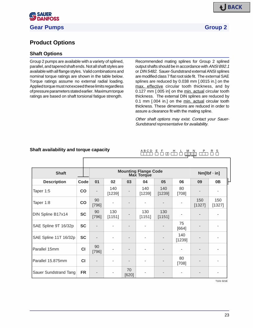
tfahS edoCegnalFgnitnuoMeuqroTxaM ]ni·fbl[mN
noitpircseD edoC 10 20 30 40 50 60 90 B0
5:1repaT OC -041
]9321[-
041]9321[
041]9321[
08]807[
- -
8:1repaT OC09
]697[- - - - -
051]7231[
051]7231[
41x71BenilpSNID CS09
]697[031
]1511[-
031]1511[
031]1511[
- - -
p23/61T9enilpSEAS CS - - - - -57
]466[- -
p23/61T11enilpSEAS CS - - - - -041
]9321[- -
mm51lellaraP IC09
]697[- - - - - - -
mm578.51lellaraP IC - - - - -08
]807[- -
gnaTdnartsdnuSreuaS RF - -07
]026[- - - - -
Group 2 pumps are available with a variety of splined,parallel, and tapered shaft ends. Not all shaft styles areavailable with all flange styles. Valid combinations andnominal torque ratings are shown in the table below.Torque ratings assume no external radial loading.Applied torque must not exceed these limits regardlessof pressure parameters stated earlier. Maximum torqueratings are based on shaft torsional fatigue strength.
Recommended mating splines for Group 2 splinedoutput shafts should be in accordance with ANSI B92.1or DIN 5482. Sauer-Sundstrand external ANSI splinesare modified class 7 flat root side fit. The external SAEsplines are reduced by 0.038 mm [.0015 in.] on themax. effective circular tooth thickness, and by0.127 mm [.005 in] on the min. actual circular tooththickness. The external DIN splines are reduced by0.1 mm [.004 in.] on the min. actual circular tooththickness. These dimensions are reduced in order toassure a clearance fit with the mating spline.
Other shaft options may exist. Contact your Sauer-Sundstrand representative for availability.
H L M N P RA B C D E F/
SShaft availability and torque capacity
T101 021E
Gear Pumps Group 2
24
Mounting flanges
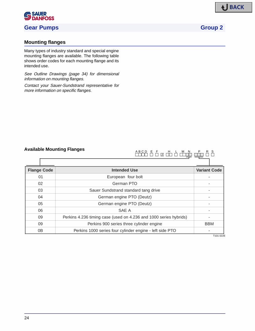
edoCegnalF esUdednetnI edoCtnairaV
10 tlobruofnaeporuE -
20 OTPnamreG -
30 evirdgnatdradnatsdnartsdnuSreuaS -
40 )ztueD(OTPenignenamreG -
50 )ztueD(OTPenignenamreG -
60 AEAS -
90 )sdirbyhseires0001dna632.4nodesu(esacgnimit632.4snikreP -
90 enignerednilyceerhtseires009snikreP MBB
B0 OTPedistfel-enignerednilycruofseires0001snikreP -
Many types of industry standard and special enginemounting flanges are available. The following tableshows order codes for each mounting flange and itsintended use.
See Outline Drawings (page 34) for dimensionalinformation on mounting flanges.
Contact your Sauer-Sundstrand representative formore information on specific flanges.
H L M N P RA B C D E F/
SAvailable Mounting Flanges
T101 022E

Gear Pumps Group 2
25
Nonstandard Port Configurations
Various port configurations are available on group 2pumps including:
• European standard flanged port
• German standard flanged port
• Gas threaded port (BSP)
• O-ring boss per SAE J1926/1 [ISO 11926-1](UNF threads)
Standard porting offered with each mounting flangetype is listed in the table below. If porting other thanstandard is desired, use the order codes shown.
See product dimensional information on page 42 for outlinedrawings and dimensions of the ports listed here.
Other ports are available on special order. Contact yourSauer-Sundstrand representative for types and availability.
edoC noitpircseD sinoitarugifnoctropsihT.segnalfesehtnodradnats
• deificepsepytegnalfehtroftropdradnatS -
B,)stropdradnatsnamreG(nrettap"X"niselohdedaerhthtiwtropdegnalF
ydobehtnoderetnecdradnatsnon
C )dradnatSnaeporuE(nrettap"+"niselohdedaerhthtiwtropdegnalF B0,10
E tropssobgnir-oEASdedaerhT 60
F )PSB(tropsaGdedaerhT dradnatsnon
G,)stropdradnatsnamreG(nrettap"X"niselohdedaerhthtiwtropdegnalF
ydobforetnecmorftesffo90,50,40,30,20
* Use only if porting is nonstandard for the flange type ordered.
H L M N P RA B C D E F/
SAvailable Porting Options
T101 023

Gear Pumps Group 2
26
Group 2 pumps are offered with an optional priorityflow divider valve integrated into the rear cover. Thepriority flow divider cover includes the following op-tions:
• Standard Priority Flow Divider Valve
• Static Load Sense Priority Flow Divider Valve
• Dynamic Load Sense Priority Flow Divider
In addition, the following choices exist for each of theabove valves:
• Pilot Relief Valve or Full Flow Relief Valve
• Rear o-ring boss ports or side o-ring boss ports
Schematic diagrams and cross sectional drawingsshowing operation of each of these valves are shown.Please refer to the product dimensional informationsection (page 42) for port location and installationdimensions.
Standard ports are:
NPF 7/8-14 UNF-2B o-ring boss
PF 9/16-18 UNF-2B o-ring boss
Other ports are available. Contact your Sauer-Sundstrand representative for more information.
Integral Priority Flow Divider Valve
Operating Range
20 4 6 8 10 12 14 16 18 20
80100 20 30 40 60 7050
0
5
10
15
20
0
1
2
3
4
5
Prio
rity
Flo
w (
US
Gal
/ m
in)
Pump Flow (US Gal / min)
Prio
rity
Flo
w (
l / m
in)
Pump Flow (l / min)
This graph shows typical flow characteristics withpriority flow set at 10 l/min. Priority flow rate varies±10% due to changes in pump flow and systempressure.
T101 024E
P101 035

Gear Pumps Group 2
27
PF NPF
i
Valve operation and performance
The standard priority flow divider valve will supplyflow to the priority port (PF) within 10% of its settingregardless of operating pressure, assuming adequatepump speed (and flow) is attained. All excess pump flowis directed to the non-priority port (NPF).
The priority flow rate is controlled by the combination ofpriority orifice diameter ‘A’ and spring force ‘C’. Thespring end of spool ‘B’ sees the pressure downstreamof priority orifice ‘A’ and the force of spring ‘C’. The non-spring end of the spool ‘B’ sees the pressure upstreamof priority orifice ‘A’. By default, all flow is directed toport ‘PF’. As flow at the priority port approaches thedesired rate, the delta pressure across orifice ‘A’increases. This delta pressure is applied to spool ‘B’.When this delta pressure overcomes the force ofspring ‘C’, the spool shifts, diverting oil to port ‘NPF’.Load pressure at port ‘PF’ is referenced to the springend of spool ‘B’, allowing the system to deliver flow atthe desired rate independent of load pressure.
Priority Flow ..................PFNon Priority Flow ..........NPFInlet ............................... iPump Output
A
B
C
NPF
PF
P101 004P101 005
P101 006

Gear Pumps Group 2
28
B
C
PF NPF
LS
i
The objective of the static load sense priority flowdivider valve is to deliver flow on demand to thepriority port (‘PF’), while compensating for pressurechanges in the load. Therefore, the load sensepriority flow divider valve does not maintain a constantflow, it maintains a constant pressure between port‘PF’ and the load sense port (‘LS’) which is connectedto the spring end of spool ‘B’. To perform this function,port ‘LS’ is connected to a point downstream of anexternal control valve that serves as a variable orifice.The flow divider valve can vary flow from zero tomaximum available flow depending on the delta pres-sure across the external control valve (∆ PF-LS).
This configuration operates essentially the same asthe standard priority flow divider except that thepriority orifice is replaced by an external variable flowcontrol valve. To maintain load pressure compensa-tion, the spring end of spool ‘B’ is now referenced toload pressure through the load sense port, whichmust be connected to a point between the externalcontrol valve and the load.
NPF
PF
LS
Priority Flow ..................PFNon Priority Flow ..........NPFLoad Sense ..................LSInlet ............................... iPump Output
P101 007P101 008
P101 009

Gear Pumps Group 2
29
PF NPF
LS
i
The dynamic load sense priority flow divider em-ploys a bleed orifice ‘D’ which allows a constantleakage of about 1 l/min or typically less, away fromthe spring end of spool ‘B’. This orifice is sized tomaintain pressure at the spring end of spool ‘B’sufficient to keep the spool in balance. In the appliedcircuit, this leakage is metered by an external valvewhich in effect controls the flow at port ‘PF’. Whenused with close tolerance rotary valving, this systemcan prevent valve locking due to sudden thermalshock. An additional benefit of this system is that thespool ‘B’ is maintained in a constant metering condi-tion before any signal input is received, thus resultingin a faster response.
Priority Flow ..................PFNon Priority Flow ..........NPFLoad Sense ..................LSInlet ............................... iPump Output
B
C
NPF
PF
LS
D
P101 010P101 008
P101 011

Gear Pumps Group 2
30
PF NPF
i
With the integral priority flow divider, two types of reliefvalves are available to protect port ‘PF’ from over-pressurization. The valves will act at a specificpressure setting as seen at port ‘PF’.
The Full Flow Relief Valve option is a direct actingrelief valve which allows flow to bypass from thepriority flow port 'PF' to the pump inlet when pressureat ‘PF’ reaches the setting. This valve is used whenfast action is required.
CAUTION: When the relief valve is operating inbypass condition, rapid heat generation will occur.If this bypass condition is maintained, prematurepump failure will result.
Priority Flow ..................PFNon Priority Flow ..........NPFInlet ............................... iPump Output
NPF
PF
P101 012P101 005
P101 013

Gear Pumps Group 2
31
The Pilot Relief Valve option opens to relieve the pilotpressure from the spring end of spool 'B' when thesetting is reached. This causes the spool to shift anddirect all flow to the non-priority port 'NPF'. It isimportant to note that the pressure setting of the pilotrelief valve is not referenced to port 'NPF'. It is alsoimportant to note that the pilot relief valve option doesnot relieve port 'PF', it only redirects pump flow. Whenthe pilot relief valve is operating, flow at port ‘NPF’ willincrease. Additional circuit pressure protection in the‘NPF’ line may be required in some applications.
PF NPF
i
Priority Flow ..................PFNon Priority Flow ..........NPFInlet ............................... iPump Output
NPF
PF
P101 014P101 005
P101 015

Gear Pumps Group 2
32
edoC noitarugifnoCDFP noitacoLtroP
RC evlaVfeileRtoliPhtiwrediviDwolFytiroirP stroPgnicaFraeR
SC evlaVfeileRtoliPhtiwrediviDwolFytiroirP stroPgnicaFediS
RL gnisneSdaoLcitatSdnaevlaVfeileRtoliPhtiwrediviDwolFytiroirP stroPgnicaFraeR
SL gnisneSdaoLcitatSdnaevlaVfeileRtoliPhtiwrediviDwolFytiroirP stroPgnicaFediS
RN gnisneSdaoLcimanyDdnaevlaVfeileRtoliPhtiwrediviDwolFytiroirP stroPgnicaFraeR
SN gnisneSdaoLcimanyDdnaevlaVfeileRtoliPhtiwrediviDwolFytiroirP stroPgnicaFediS
RQ evlaVfeileRwolFlluFhtiwrediviDwolFytiroirP stroPgnicaFraeR
SQ evlaVfeileRwolFlluFhtiwrediviDwolFytiroirP stroPgnicaFediS
RR gnisneSdaoLcitatSdnaevlaVfeileRwolFlluFhtiwrediviDwolFytiroirP stroPgnicaFraeR
SR gnisneSdaoLcitatSdnaevlaVfeileRwolFlluFhtiwrediviDwolFytiroirP stroPgnicaFediS
RV gnisneSdaoLcimanyDdnaevlaVfeileRwolFlluFhtiwrediviDwolFytiroirP stroPgnicaFraeR
SV gnisneSdaoLcimanyDdnaevlaVfeileRwolFlluFhtiwrediviDwolFytiroirP stroPgnicaFediS
H L M N P RA B C D E F/
SOrder Codes
T101 025E
wolFdellortnoC]nim/lagSU[nim/l
edoC
]11.2[8 M
]46.2[01 F
]71.3[21 N
]07.3[41 O
]32.4[61 P
]57.4[81 J
]82.5[02 Q
]08.5[22 K
]43.6[42 R
]68.6[62 I
gnitteSerusserP]isp[rab
edoC
]078[06 L
]5101[07 M
]0611[08 N
]5031[09 O
]0541[001 P
]5951[011 Q
]0471[021 R
]5881[031 S
]0302[041 T
]5712[051 C
]0232[061 U
]5642[071 D
]1162[081 V
]5572[091 E
]1092[002 X
H L M N P RA B C D E F/
SUVariant Codes
The tables to the right show applicable variant codesfor flow and pressure settings necessary when order-ing pumps with integral priority flow divider. Refer tothe Model Code (page 8,9) for more information.
T101 026E
T101 027E
Order Codes for Integral Priority Flow Divider
The table below shows order coding necessary tospecify the desired options and porting locations. Referto the Model Code (page 8,9) for more information.

Gear Pumps Group 2
33
Bar
0
1000
2000
3000
4000
5000
Psi
0 10 20 30 40 l/min
0 2 4 6 8 10 US Gal/min
0
100
200
300
400
MINIMUM VALVE SETTING
Integral Relief Valve (SNE 2 / SNI 2)Group 2 pumps are offered with an optionalintegral relief valve in the rear cover . This valve canhave an internal (SNI 2) or external (SNE 2) drain.This valve opens directing all flow from the pumpoutlet to the drain when the pressure at the outletreaches the valve setting. This valve can be orderedpreset to the pressures shown in the table below.Valve schematic, performance curve, and rear covercross section are shown here.
CAUTION: When the relief valve is operating inbypass condition, rapid heat generation will occur.If this bypass condition is maintained, prematurepump failure will result. When frequent operation isrequired, external drain option (SNE 2) must beused.
The tables to the left show applicable variant codes forordering pumps with integral relief valve. Refer to theModel Code (page 8,9) for more information.
i = Inlet
o = Outlet
e = External Drain
i
o
i
o
e
VRrofdeepSpmuPnim-gnitteS 1- )mpr(
edoC
denifeDtoN A
005 C
0001 E
0521 F
0051 G
0002 K
0522 I
0052 L
0082 M
0003 N
gnitteSerusserP]isp[rab
edoC
gnitteSoN A
evlaVoN B
]162[81 C
]534[03 E
]805[53 F
]085[04 G
]527[05 K
]078[06 L
]5101[07 M
]0611[08 N
]5031[09 O
]0541[001 P
]5951[011 Q
]0471[021 R
]5881[031 S
]0302[041 T
]0232[061 U
]5642[071 V
]5572[091 X
]5403[012 Y
]5333[032 Z
H L M N P RA B C D E F/ V
OutletInlet
T101 030E
P101 016
P101 017 P101 018T101 028E
T101 029E
Variant Codes for Ordering Integral Relief Valve

Gear Pumps Group 2
34
An Outrigger Bearing is available for applicationswith high radial or thrust loads on the shaft. Thisoption is used primarily for applications with high shaftloads such as to belt or chain drives. The designutilizes roller bearings in the front mounting flange.These bearings absorb the radial and thrust loads onthe shaft so that the life of the pump is not affected.The use of roller bearings allows life to be describedin B
10 hours. The graph to the right shows allowable
shaft loads for 1000 hour life at 1500 rpm versusdistance from flange face to center of radial load.
Outrigger Bearing Assembly
T101 031EP101 036E
P101 019
H L M N P RA B C D E F/
S9
T101 046E
Available Configurations
edoC tfaS egnalFgnitnuoM tnairaV
19OC 8:1repaT tlobruofnaeporuE DBL
49OC 5:1repaT tlobruofnamreG ...
69IC lellaraP AEAS PEL
0
500
1000
1500
2000
2500
3000
3500
10 20 30 40 50 60
Radial Load
Axial Load
SNP2/...CO94SNP2/...CI96SNP2/...CO91
.25 .5 .75 1 1.25 1.5 1.75 2 2.25
Distance a (mm)
Distance a (in.)
Load
(N
)
Load
(lb
f)
0
100
200
300
400
500
600
700
800
Distance from flangeface to center ofradial load

Gear Pumps Group 2
35
H L M N P RA B C D E F/
SS C 3 6
SAE A Pad
SAE J498-9T-16/32DP-flat root side fit
A 17x14 DIN 5482
o-ring
M10-6H thru
T101 032E
P101 020E
Auxiliary Mounting PadsSAE “A” auxiliary mounting pads are available on allgroup 2 pumps with SAE front flanges. These padsare used for mounting auxiliary hydraulic pumps orcreating special tandem gear pumps. (For standardmultiple pumps, see Multiple Pump Technical Manual.)Since the drive coupling is lubricated with oil from themain pump inlet, an o-ring must be used to seal theauxiliary pump mounting flange to the pad. Specifica-tions and torque ratings are shown in the accompany-ing table.
• The combination of auxiliary mounting pad shafttorque, plus the main pump torque should notexceed the maximum pump input shaft ratingshown in the “Shaft Availability and TorqueRatings” table on page 23.
• All torque values assume a 58 HRc shaft splinehardness on mating pump shaft.
See product dimensional information section(page 45) for outline drawings with the dimensionsof the auxiliary pump mounting flange and shaft.
Auxiliary Mounting Pad Specifications
yrailixuAepyTdaP
epyTgnilpuoCgnitaReuqroTmumixaM
]ni·fbl[mN
"A"EAS hctip23/61htoot9 ]466[57

Gear Pumps Group 2
36
mm[in]
(min full thd 12mm [.472] deep)
1 : 8
A
A
Section : A-AM
12x1
.25-
6g
E/e
40.5 [1.596]
Ø 1
6.66
2 [.6
56]
11.95-12.7 [.471-.473] 16.05 [.632] max
17 [.670]
B max
18 [.709] 5 [.020]
C/c
M6
Thr
ead
16m
m [.
630]
dee
p
Section :B-B
B
B
6.5 [.256]
30 [1.182]
36.5 [1.438]
Spl
ine
B17
x14
DIN
548
2
prof
ile o
ffset
-0.
1 [.0
04]
6.5 [.256]
10 [.394]
19.5 [.768]
body width
(96.
2 [3
.790
])
115.
2 [4
.539
] max
9 [3.55]
90 [3.546] max
D/d ±0.20 [.008]
A ±0.50 [.020]
(41.
9 [1
.651
])
71.5[2.817]
63.8
[2.5
14]
32.4
[1.2
77]
(73.
3 [2
.888
])
90 ±.25 3.546 ±.010[ ]
15.7
±0.
50[
].6
19±
.020
4 +0 +0-0.030 [ ].158 -.001
9.5
+0.
15+
.006
-0.2
5[
].3
74-.
010
16.5
Ø+
0-0
.110
+0 -.00
4[
].6
50
-0.0
25-0
.064
36.5
Ø+
.001
-.00
3[
]1.
438
16.5
+0.
10-0
.20
+.0
04-.
008
[]
.650
15Ø
+0
-0.0
18+
0 -..0
01[
].5
91
4 +0-0.030
+0-.001[ ].158
X
Ø 0.75 [.030] X
)tnemecalpsid(epyT4 6 8 11 41 71 91 22 52
snoisnemiDA
52.34]307.1[
54]277.1[
54]277.1[
94]929.1[
25]740.2[
25]740.2[
65]502.2[
95]323.2[
95]323.2[
B09
]345.3[5.39
]186.3[5.79
]938.3[5.101]699.3[
5.701]232.4[
5.111]093.4[
5.511]745.4[
5.121]387.4[
5.521]149.4[
telnI
C ]135.[5.31 ]787.[025.32
]529.[
D ]181.1[03 ]575.1[0404
]575.1[
E 6M 8M 8M
teltuO
c ]135.[5.31 02
d ]181.1[03 04
e 6M 8M
SC01 CI01 CO01
nut and washer supplied with pump
*
**
* Add 3mm [.118in] for SHP 2 pumps. **Add 6mm [.236in] for SHP 2 pumps.
P101 021ET101 033E
Product Dimensional Information
SC01 / CI01 / CO01
Standard porting and rear cover shown. See page 42for additional porting options. See page 43 for valveoptions. See page 44 for outrigger bearing options.

Gear Pumps Group 2
37
mm[in]
Spline
B17x14 DIN 5482
profile offset -0.1 [.004]
13.5 [.531]
23.5 [.952]
1 : 5
A
Section : A-A
A
M12
x1.2
5-6g
16.5 [.650]
E/e
17.4
6[.6
87]
38 [1.496]B max
12.5 [.492] 7.2 [.283]
5.7 [.224] 19.3 [.760]
C/c
45°
body width
9 [.354]
(100
[3.9
37])
D/d ±0.20 [.008]
A ±0.50
72[2.835]
120
[4.7
24] m
ax
92 [3.622] max
(44.
5 [1
.72]
)
65.5
[2.5
79]
34.5
[1.3
58]
(75.
5 [2
.972
])
90 ±0.25 ±.0103.543[ ]
Ø16
.5+
0 -0.1
10+
0-.
004
[]
.650
Ø80
+0.
060
-0.1
06+
.002
-.00
4[
]3.
150
3 +0-0.025
+0-.001[ ].118
9+
0.30
-0.1
0+
.012
-.00
4[
].3
54
15.7
±0.
50+
.020
[]
0.61
8
) Ø0.75 [.030] X
X
(min full thd 12mm [.472] deep)
)tnemecalpsid(epyT4 6 8 11 41 71 91 22 52
snoisnemiDA
8.93]765.1[
1.14]816.1[
1.34]796.1[
]078.1[5.7455
]561.2[5.46
]935.2[
B5.29
]246.3[69
]087.3[001
]739.3[401
]490.4[011
]133.4[411
]884.4[811
]646.4[421
]288.4[821
]930.5[
telnI
C ]195.[51 ]787.[02
D ]575.1[04
E 6M
teltuO
c ]195.[51
d ]873.1[53
e 6M
SC02 CO02
nut and washer supplied with pump
**
**Add 6mm [.236in] for SHP 2 pumps.
P101 022ET101 034E
SC02 / CO02Standard porting and rear cover shown. See page 42for additional porting options. See page 43 for valveoptions.

Gear Pumps Group 2
38
mm[in]
(min full thd 12mm [.477] deep)E/e
Ø34
[1.3
51]
7.2 [.286]
Ø19
[.75
5]
Ø30
[1.1
92]
12 [.477]
C/c
45°
X
o-ring 45.69x2.62
2 [.079]
==
body width
(60
[2.3
84])
D/d ±0.20
B ±0.50 [±.202]
A ±0.50 [±.202]
(60 [2.384])
103
[4.0
92] m
ax
30[1.192]
45.7
[1.8
16]
14.3
[.568
]
30[1.192]
Ø52
+0.
030
-0.0
76+
.001
-.00
3[
]2.
066
8+
0.02
5-0
.083
+.0
01-.
003
[]
.318
3.2 +0.20-0
+.008-0[ ].127
11.5 +0.27-0
+.011-0[ ].457
2.7 +0.60-0
+.024-0[ ].1076.5+0.20
-0+.008-0[ ].258
Ø47
.8+
0 -0.2
0+
0-.
008
[]
1.89
9
15.7
±0.
50±
0.02
0[
].6
24
90 ±0.25 ±0.010[ ]3.576
)Ø
0.75
[.03
0] X
8 [.315]
)tnemecalpsid(epyT4 6 8 11 41 71 91 22 52
snoisnemiDA
3.73]964.1[
6.83]025.1[
6.04]895.1[
]277.1[545.25
]760.2[26
]144.2[
B09
]345.3[5.39
]186.3[5.79
]938.3[5.101]699.3[
5.701]232.4[
5.111]093.4[
5.511]745.4[
5.121]387.4[
5.521]149.4[
telnI
C ]195.[51 ]787.[02
D ]575.1[04
E 6M
teltuO
c ]195.[51
d ]873.1[53
e 6M
coupling supplied with pump
**
**Add 6mm [.236in] for SHP 2 pumps.
P101 023ET101 035E
FR03Standard porting and rear cover shown. See page 42for additional porting options. See page 43 for valveoptions.

Gear Pumps Group 2
39
mm[in]
**04 Body±
0.50
15.7
±.0
01[
].6
18
A ±0.50 [.020]
B ±0.50 [.020]
+0.27-011.5 +.011
-0[ ].453
SplineB17x14 DIN 5482profile offset -0.1 [.004]
13.5 [.531]
26 [1.024]
Section : A-A
A
A
1 : 5
X
(min full thd 12mm [.472] deep)
M12
x1.2
5-6g
17.4
6[.6
87]
19 [.748]
E/e
7.2 [.283]
40.5 [1.594]
8.2 [.323] 19.3 [.760]
C/c
45°
body width
== (6
0 [2
.362
])
D/d ±0.20
90 ±0.25 [.010]
(60 [2.362])
103
[4.0
55] m
ax
45.7
[1.7
99]
14.3
[.563
]
30[1.181]
30[1.181]
) Ø0.75 [.030] X
+0 -0
.110
Ø16
.5+
0 -.00
4[
].6
50
+0.
025
-0.0
64Ø
50+
.001
-.00
3[
]1.
969
+0.
30-0
.10
9+
.012
-.00
4[
].3
54
+0-0.0253 +0
-.001[ ].118
)tnemecalpsid(epyT4 6 8 11 41 71 91 22 52
snoisnemiDA
3.73]964.1[
6.83]025.1[
6.04]895.1[
]277.1[545.25
]760.2[26
]144.2[
B09
]345.3[5.39
]186.3[5.79
]938.3[5.101]699.3[
5.701]232.4[
5.111]093.4[
5.511]745.4[
5.121]387.4[
5.521]149.4[
telnI
C ]195.[51 ]787.[02
D ]575.1[04
E 6M
teltuO
c ]195.[51
d ]873.1[53
e 6M
SC04/05 CO04/05**05 Body
nut and washer supplied with pump
Notes: 04 and 05 flanges differ only in theirmounting bolt positions. All otherdimensions are common.
Special limitations may apply whenused with gear drive (see page 15).
**
**Add 6mm [.236in] for SHP 2 pumps.
P101 024ET101 036E
SC04 / SC05 / CO04 / CO05Standard porting and rear cover shown. See page 42for additional porting options. See page 43 for valveoptions. See page 44 for outrigger bearing options.

Gear Pumps Group 2
40
mm[in]
12 [.472]6 [.236]
Splined
FLAT ROOT SIDE FIT
(circular tooth thickness
0.127 mm [.005] less than
standard class 1 fit)
SAE J498-11T-16/32DP
38 [1.496]
10.5 [.413]
Ø18
.631
[.73
4]
Splined
SAE J498-9T-16/32DP
FLAT ROOT SIDE FIT
(circular tooth thickness
0.127 mm [.005] less than
standard class 1 fit)
20 [.787]
31.7 [1.248]
23.8 [.937] 7.9 [.311]
TH
D 1
6mm
[.63
0] d
eep
A
A
Section : A-A
7.9 [.311] 23.8 [.937]
B max 31.7 [1.248]
C/c
M6-
6H-
17.4
75-1
7.72
9[.6
88 -
.698
]
12 [.472] 6 [.236]
body width
11 -
11.
6 [.4
33 -
.457
]A ±0.50 [.020]
132 [5.197] max
106.38 [4.188]11
5.5
[4.5
47] m
ax
R48
max
Ø15
.456
+0 -0
.127
+0 -.00
5[
].6
09
Ø82
.55
+0 -0
.050
+0 -.02
0[
]3.
250
3.995 +0-0.025
+0-.010[ ].157
Ø15
.875
+0 -0
.025
+0 -.01
0[
].6
25
90±0.25 ±.010[ ]3.543 15.7
±0.
50±
.020
[]
.618
)Ø
0.75
[.03
0] X
X
straight threado-ring bossstraight threado-ring boss
)tnemecalpsid(epyT4 6 8 11 41 71 91 22 52
snoisnemiDA
52.34]307.1[
54]277.1[
74]058.1[
94]029.1[
25]740.2[
45]621.2[
65]502.2[
95]323.2[
16]204.2[
B09
]345.3[5.39
]186.3[5.79
]938.3[5.101]699.3[
5.701]232.4[
5.111]745.4[
5.511]093.4[
5.121]387.4[
5.521]149.4[
telnI C1(360.1 1/ 61 B2-NU21-)
peed]907.[mm81
teltuO c(578. 7/8 B2-FNU41-)
peed]856.[mm7.61
SKP2
SC06 CI06SC06
P101 025ET101 037E
SC06 / CI06Standard porting and rear cover shown. See page 42for additional porting options. See page 43 for valveoptions. See page 44 for outrigger bearing options.

Gear Pumps Group 2
41
mm[in]
1:8
B
B
Section: B - B
ø17
.46
[.687
]
M12
x1.2
5-6g
-
21.7 [.854]
B max
14-15 [.551-.591]
9 [.354]
0.8 max
R
10.5 [.413]
R
19°
31.5
[1.2
40]
3/8-
16U
NC
-2B
122.5 [4.823] max
(99.6 [3.921])
103
[4.0
55] m
ax
(69
[2.7
17])
(34
[1.3
39])
19 [.748]
(R11.45
[.451] max)(R
11.4
5 [.4
51] m
ax)
R35[1
.378
]
49.2[1.937]
50.4[1.984]
17.2 ±0.75 ±.030[ ].677
40.5 ±1 ±.039[ ]1.594
4.5 ±0.25 ±.010[ ].177
90±
0.25
±.0
10[
]3.
543
12.5±0.50 ±.020[ ].492
6.3 ±0.75 ±.030[ ].248
15.7
±0.
50±
.020
[]
.618
9.5 +0.15 +.006-0.25 -.010[ ].374
1.7+0.15
+.006
-0
-0
[]
.067
3+
0+
0-0
.025
-.00
1[
].1
18
Ø52
.34
+0
+0
-0.0
5-.
020
[]
2.06
1
)Ø
0.75
[.03
0] X
X
E/e
C/c
D/d
A ±0.50 [.020]
(min full thd 12mm [.472] deep)
)tnemecalpsid(epyT4 6 8 11 41 71 91 22 52
snoisnemiDA
3.73]964.1[
6.83]025.1[
6.04]895.1[
]277.1[545.25
]760.2[26
]144.2[
B09
]345.3[5.39
]186.3[5.79
]938.3[5.101]699.3[
5.701]232.4[
5.111]093.4[
5.511]745.4[
5.121]387.4[
5.521]149.4[
telnI
C ]195.[51 ]787.[02
D ]575.1[04
E 6M
teltuO
c ]195.[51
d ]873.1[53
e 6M
Note: Special limitations may apply when usedwith gear drive (see page 15). P101 026E
T101 038E
CO09Standard porting and rear cover shown. See page 42for additional porting options. See page 43 for valveoptions.

Gear Pumps Group 2
42
mm[in]
1:8
B
B
Section:B - B
21.7 [.854]
M12
x1.2
5-6g
-
Ø17
.46
[.687
]
3+
0+
0-0
.025
-.00
1[
].1
18
9.5+0.15 +.006-0.25 -.010[ ].374
903.
543
± 0.2
5±
.010
[]
6.3 .248±0.75 ±.030[ ]
17.2 .677±0.75 ±.030[ ]
12.5 .492±0.50 ±.020[ ]
B max
R0.8 [.031] max
14-15 [.551-.591]
3/8-
16U
NC
-2B
(99.6 [3.921])
122.5 [4.823] max
109
[4.2
91] m
ax
R38
[1.4
96] m
ax(R11.45 [.451] max)
13°
50.4[1.984]
49.2[1.937]
3.85
+0.1
5+.
006
-0
-0[
].1
52
Ø9.
5+
0+
0-0
.05
-.02
0[
].3
74
15.7
.618
± 0.5
0±
.020
[]
4 .157±0.25 ±.010[ ]
40.5 1.594±1 ±.039[ ]
X
)Ø
0.75
[.03
0] X
Min. full thread12mm [.472] deep
E/e
C/c
D/d
A±0.50 [.020]
)tnemecalpsid(epyT4 6 8 11 41 71 91 22 52
snoisnemiDA
3.73]964.1[
6.83]025.1[
6.04]895.1[
]277.1[545.25
]760.2[26
]144.2[
B09
]345.3[5.39
]186.3[5.79
]938.3[5.101]699.3[
5.701]232.4[
5.111]093.4[
5.511]745.4[
5.121]387.4[
5.521]149.4[
telnI
C ]195.[51 ]787.[02
D ]575.1[04
E 6M
teltuO
c ]195.[51
d ]873.1[53
e 6M
Note: Special limitations may apply when usedwith gear drive (see page 15).
P101 027ET101 039E
CO09 (variant BBM)Standard porting and rear cover shown. See page 42for additional porting options. See page 43 for valveoptions.

Gear Pumps Group 2
43
mm[in]
34.8
[1.3
70]
66.2
[2.6
06]
port facing45.0 [1.772]
port facing45.0 [1.772]
C
shaf
t
dia C
3.9 [.154]
2.5 [.098]
A
20.3[.799]
9.75 [.384]
B
15.7
[.61
8]
min full thread
shaft
shaf
t
dia
C
through
1.52
[.060
]
6.99 [.275]
58.3
8 [2
.298
]
16.9
7[.6
68]
37.0
0[1
.457
]
53.7
5 [2
.116
]
27.0
7[1
.066
]
64.41 [2.536]
48.06[1.892]
49.05 [1.931]
8.00 [.315]
53.00[2.087]
13.65 [.537]
30.2
4[1
.191
]
M8x1.25 x 13.0
R9.0 [.354] typ
5 holes ø9.0 [.354]
33.8 [1.331]31.8 [1.252]
94.9
75 [3
.739
]90
.055
[3.5
45]
Ø
90.3
00 [3
.555
]90
.940
[3.7
38]
Ø
11.4 [.449]8.6 [.339]
C/c
D/d
E/emin full thd 12mm [.472]
ataDraeGlanretxEhteetforebmuN 82
lamroneludoM ]001.[45.2
esrevsnarteludoM ]301.[816.2
lamronelgnaerusserP °02
esrevsnartelgnaerusserP °7275.02
retemaidelcrichctiP ]788.2[43.37
elgnaxileH °331.41
xilehfodnaH dnahtfeL
htpedhtootlluF ]532.[79.5
retemaidelcricesaB ]207.2[366.86
hteet4revonoisnemiD861.82-702.82]901.1-111.1[
)tnemecalpsid(epyT4 6 8 11 41 71 91 22 52
snoisnemiDA
50.94]139.1[
8.05]000.2[
8.05]000.2[
8.45]751.2[
8.75]672.2[
8.75]672.2[
8.16]334.2[
8.16]334.2[
8.46]155.2[
B3.59
]257.3[8.89
]098.3[8.201]740.4[
8.601]502.4[
8.211]144.4[
8.611]895.4[
8.021]657.4[
8.621]299.4[
031]811.5[
telnI
C ]135.[5.31 ]787.[02
D ]181.1[03 ]575.1[04
E 6M 8M
teltuO
c ]135.[5.31
d ]181.1[03
e 6M
P101 028E
T101 040
T101 041E
CO0BStandard porting and rear cover shown. See page 42for additional porting options. See page 43 for valveoptions.
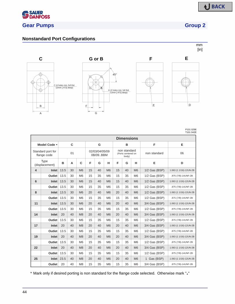
Gear Pumps Group 2
44
mm[in]
∗ Mark only if desired porting is non standard for the flange code selected. Otherwise mark "."
E DF
G
45°
H (4 holes min. full thd.12mm [.472] deep)
B
A
C (4 holes min. full thd.12mm [.472] deep)
C G or B F E
snoisnemiD
edoCledoM * C G B F E
roftropdradnatSedocegnalf
1090/50/40/30/20
MBB..90/B0
dradnatsnonnoderetnecstroP(
)ydobdradnatsnon 60
epyT)tnemecalpsid(
B A C F G H F G H E D
4 telnI 5.31 03 6M 51 04 6M 51 04 6M )PSB(saG2/1 B2-NU21-)61/11(360.1
teltuO 5.31 03 6M 51 53 6M 51 53 6M )PSB(saG2/1 B2-FNU41-)8/7(578.
6 telnI 5.31 03 6M 51 04 6M 51 04 6M )PSB(saG2/1 B2-NU21-)61/11(360.1
teltuO 5.31 03 6M 51 53 6M 51 53 6M )PSB(saG2/1 B2-FNU41-)8/7(578.
8 telnI 5.31 03 6M 02 04 6M 02 04 6M )PSB(saG2/1 B2-NU21-)61/11(360.1
teltuO 5.31 03 6M 51 53 6M 51 53 6M )PSB(saG2/1 B2-FNU41-)8/7(578.
11 telnI 5.31 03 6M 02 04 6M 02 04 6M )PSB(saG4/3 B2-NU21-)61/11(360.1
teltuO 5.31 03 6M 51 53 6M 51 53 6M )PSB(saG2/1 B2-FNU41-)8/7(578.
41 telnI 02 04 8M 02 04 6M 02 04 6M )PSB(saG4/3 B2-NU21-)61/11(360.1
teltuO 5.31 03 6M 51 53 6M 51 53 6M )PSB(saG2/1 B2-FNU41-)8/7(578.
71 telnI 02 04 8M 02 04 6M 02 04 6M )PSB(saG4/3 B2-NU21-)61/11(360.1
teltuO 5.31 03 6M 51 53 6M 51 53 6M )PSB(saG2/1 B2-FNU41-)8/7(578.
91 telnI 02 04 8M 02 04 6M 02 04 6M )PSB(saG4/3 B2-NU21-)61/11(360.1
teltuO 5.31 03 6M 51 53 6M 51 53 6M )PSB(saG2/1 B2-FNU41-)8/7(578.
22 telnI 02 04 8M 02 04 6M 02 04 6M )PSB(saG4/3 B2-NU21-)61/11(360.1
teltuO 5.31 03 6M 51 53 6M 51 53 6M )PSB(saG2/1 B2-FNU41-)8/7(578.
52 telnI 5.32 04 8M 02 04 6M 02 04 6M )PSB(saG1 B2-NU21-)61/11(360.1
teltuO 02 04 8M 51 53 6M 51 53 6M )PSB(saG4/3 B2-FNU41-)8/7(578.
P101 029ET101 042E
Nonstandard Port Configurations

Gear Pumps Group 2
45
mm[in]
VIEW WITHNO RELIEF
VALVE SHOWN
64.95 [2.557]
14.4
0 [.5
67]
15.0
0[.5
91]
66.05 [2.600]
91 [3.583]
65.5 [2.579]
23.8
7 [.9
40]
49.70 [1.957]
93.2
5 [3
.671
]
25.1
5 [.9
90]
94.1
5[3
.707
]
50.30 [1.980]
[.925]23.50
25.1
7[.9
91]
26.0
5[1
.026
]
POSITION OFOPTIONAL FULLFLOW VALVE
SHAFT
ø34
.0 [1
.334
]
88.8 [3.496]
80.3
0 [3
.161
]79
.10
[3.1
14]
38.2
0 [1
.504
]
51.10 [2.011]
[1.083]27.5
SHAFT39.4
0[1
.551
]
2 ALTERNATIVES,WITH OR WITHOUT
LOAD SENSE PORTS
AX
IAL
RA
DIA
L
2 ALTERNATIVENON PRIORITY
PORT POSITIONS
RADIAL
AXIAL
2 ALTERNATIVEPRIORITY PORT
POSITIONS
WITH WIT
HO
UT
OPTIONAL PILOTRELIEF VALVE
7/16"-20UNFOR 1/4"BSPOR M10x1.25
[2.511] 63.7751.90 [2.043]
[1.220]31.0
15.7
0[.6
18]
A
31.5 [1.24] maxA
SHAFT
M12x1.5-6H 12mm deep
DRAIN (SNE only)
93 [3.661] max
41.7 [1.642]
)tnemecalpsid(epyTnoisnemiD 4 6 8 11 41 71 91 22 52
2PKS/2PNS *A5.86
]796.2[27
]538.2[67
]299.2[08
]051.3[68
]683.3[09
]345.3[49
]107.3[001
]739.3[401
]490.4[
2PHS *A001
]739.3[601
]371.4[011
]133.4[
* For 02 flange add 2.5mm [.098 in]
P101 030E
T101 043E
P101 031E
Integral Priority Flow Divider Cover and Integral Relief Valve Cover

Gear Pumps Group 2
46
mm[in]
SNP2/... CI96 LEP..
SNP2/... CO94 .....
SNP2/... CO91 LBD..
6.5-8.5[.256-.335]
43 [1.693 ]-.15+.006-.006
+.15
46.5 1.831[ ]-.15+.006-.006
+.15
35
1.378[ ]-.15
+.006-.006
+.15 43.5
1.713[ ]-.15
+.006-.006
+.15
20.9
00-2
1.12
5[.8
23-.
832]
4.755
.187[ ]-.030
+.0-.0012
+.0
19.05
.187[ ]-.033
+.0-.0013
+.0 Variant LEP
3.2 .126[ ]-.025+.0-.0010
+.0
9.5
.374
[]
-.35
+.0
06-.
014
+.1
5
Variant LBD
A ±0.50 [.020]
B ±0.50 [.020]
C ±0.50 [.020]
D max
)tnemecalpsid(epyT4 6 8 11 41 71 91 22 52
snoisnemiD
A52.52
]499.0[72
]360.1[72
]360.1[13
]022.1[43
]933.1[43
]933.1[83
]694.1[14
]416.1[14
]416.1[
B3.73
]964.1[6.83
]025.1[6.04
]895.1[54
]277.1[54
]277.1[54
]277.1[54
]277.1[5.25
]760.2[26
]144.2[
C52.34
]307.1[54
]277.1[74
]058.1[94
]029.1[25
]740.2[45
]621.2[65
]502.2[95
]323.2[16
]204.2[
D341
]036.5[051
]609.5[851
]022.6[661
]535.6[871
]800.7[681
]323.7[491
]836.7[602
]011.8[412
]524.8[
P101 032ET101 044E
Outrigger Bearings

Gear Pumps Group 2
47
mm[in]
scre
ws
prov
ided
M10
x30
UN
I593
1 8G
br.
reco
mm
ende
d to
rque
:40
-50N
m [3
0-37
lb•f
t]
was
hers
prov
ided
10 U
NI 1
750
R40
br
o-rin
gpr
ovid
ed82
.22x
2.62
[3.2
37x.
103]
X K
X
YM10-6H
Z
X
C/c
=
A
A
=
122
[4.8
03] m
ax
115.
5 [4
.547
] max
19.5
[.76
8] m
ax
106.38 [4.188]
106.38 [4.188]
132 [5.197] max
132 [5.197] max
(R12
.7[.5
00] m
ax)96 [3.780] m
ax
96 [3.780] max
ø 0.50 [.020]
= =
90.5 [3.563] max
19.5
[.76
8] m
ax
R12.7
[.500
] max
(min full thd 16.7mm [.657] deep)
ø 0
.35
[.014
]
ø 0
.10/
25.4
[.00
4/1]
SA
E J
498-
9T-1
6/32
DP
-fla
t roo
t sid
e fit
circ
ular
thic
knes
s 0.
127
mm
less
than
sta
ndar
d cl
ass
1 fit
[.005
]
Straight thread o-ring boss
A 17x14 DIN 5482
Z
0.10
[.00
4]
Sec
tion.
:A-A
ø 0
.75
[.030
]11
.6-1
1 [.4
57-.
433]
0-3°
arrow indicates direction of rotation and outlet port
SAE J498-9T-16/32DP-flat root side fit
ø 0
.35
[.01
4]S
plin
e:B
17 x
14
DIN
548
2
prof
ile o
ffset
+0.
600
[.025
]
K
X
ø 0
.40
[.016
]
Y
Y
B ±0.50 [.020]
A ±0.50 [.020]
(31.7 [1.248])
11.5-12.5 [.453-.492]
40.5 ±0.25 ±.010[ ]1.594
90±0
.25
±.01
0[
]3.
543
7 ±0.20 ±.008[ ].276
34.5 ±1.2 ±.047[ ]1.358
51.5 ±0.90 ±.035[ ]2.028
15.7
±0.5
0±.
035
[]
.618
23.8 ±0.25 ±.010[ ].9377.9 ±0.75 ±.030[ ].311
20 ±0.75 ±.030[ ].787
Ø15
.456
+0
+0
-.00
5-0
.127
[]
.609
3 +.006+0.15-0-0 [ ].118 6.35 +0+0
-.020-0.50 [ ].250
Ø16
.5+
0+
0-.
004
-0.1
10[
].6
50Ø82
.55
+.0
03+
0.07
7-.
001
-0.0
23[
]3.
250
Ø82
.55
+.0
03+
0.07
7-.
001
-0.0
23[
]3.
250
Ø87
+.0
02+
0.05
-.00
6-0
.15[
]3.
425
)tnemecalpsid(epyT4 6 8 11 41 71 91 22 52
snoisnemiDA
52.34]307.1[
54]277.1[
74]058.1[
94]029.1[
25]740.2[
45]621.2[
65]502.2[
95]323.2[
16]204.2[
B461
]754.6[061
]992.6[451
]360.6[051
]609.5[641
]847.5[041
]215.5[631
]453.5[231
]791.5[5.821]950.5[
telnI C1(360.1 1/ 61 B2-NU21-)
peed]907.[mm81
teltuO c(578. 7/8 B2-FNU41-)
peed]856.[mm7.61
P101 033ET101 045E
Coupling, o-ring, and screws supplied with pump.
Auxiliary Mounting Pad
SAUER-SUNDSTRAND Hydraulic Power Systems - Market Leaders Worldwide
SAUER-SUNDSTRAND specializes in integrating a fullrange of system components to provide vehicle designerswith the most advanced total-design system.
SAUER-SUNDSTRAND is Your World Source forControlled Hydraulic Power Systems.
SAUER-SUNDSTRAND is a world leader in the design andmanufacture of Hydraulic Power Systems. Research anddevelopment resources in both North America and Europeenable SAUER-SUNDSTRAND to offer a wide range ofdesign solutions utilizing hydraulic power systemtechnology.
Worldwide Service Support
SAUER-SUNDSTRAND provides comprehensive worldwide service for itsproducts through an extensive network of Authorized Service Centersstrategically located in all parts of the world.
Look to SAUER-SUNDSTRAND for the best in WORLDWIDE SERVICE.
Genuine Service PartsGear Pumps and MotorsOpen Circuit Axial Piston Pumps
Hydraulic Power Systems
Cartridge Motors/Compact Wheel Drives
Heavy Duty Bent AxisVariable Motors
Heavy Duty Axial PistonPumps and Motors
Hydrostatic TransmissionPackages
Medium Duty Axial PistonPumps and Motors
Microcontrollers andElectrohydraulic Controls
SAUER-SUNDSTRAND COMPANY2800 East 13th Street • Ames IA 50010 • U.S.A.Phone: (515) 239-6000 • FAX: (515) 239-6618
http://www.sauer.com
SAUER-SUNDSTRAND GMBH & CO.Postfach 2460 • D-24531 NeumünsterKrokamp 35 • D-24539 Neumünster • GermanyPhone: (04321) 871-0 • FAX: (04321) 087 122
BLN - 10071 • Revision A • September 1998


![NORTA MIT PRESENTATION.pptx [Read-Only] · • Centrifugal pumps • Side channel pumps • Gear pumps • Screw pumps • Single screw pumps • Piston pumps • Vacuum pumps •](https://static.fdocuments.us/doc/165x107/5ec27ab9e3ef591d10504c3a/norta-mit-read-only-a-centrifugal-pumps-a-side-channel-pumps-a-gear-pumps.jpg)