Ground... · The lighting system used on the runways, taxiways, and stop bars continues to grow...
16
Stay on the Safe Side
Transcript of Ground... · The lighting system used on the runways, taxiways, and stop bars continues to grow...
S t a y o n t h e S a f e S i d e
������������������� �������

2
Permanent Control and Monitoring
Today’s commercial airports use
state-of-the-art technologies to
safely and optimally master operat-
ing procedures whose complexity
is steadily increasing. The lighting
system used on the runways,
taxiways, and stop bars continues
to grow unabated. In order to easily
control and monitor this equipment,
despite its complexity and the
additional strict safety regulations,
Honeywell has developed a com-
puterized control and monitoring
system for airport lighting equip-
ment. In addition to a comfortable
working environment for tower
controllers and technicians, this
system offers a number of practical
Honeywell Network and System Monitoring
Control and monitoring system for airport lighting
equipment
Taxiingcontrol
functions
Open Data Interface
Workstation Management
Runway Control
Event Records
Technical Monitoring
AFL
Local Control for
Maintenance
Control and Monitoring of
CCRs and other Systems
Taxiway Control
Aproncontrol
Automaticrouting
Sensor dataprocessing
Docking-system
Visual Docking
Guidance System
Monitoring the series circuits
Single lamp control an monitoring
Date interfacewith data filtering
functions that make daily work
noticeably easier, and ensure that
the airport lighting system can be
monitored in an ideal way. It goes
without saying that this system
meets all of the International Civil
Aviation Organization’s (ICAO)
recommendations, including failure
monitoring of adjacent lamps
through the use of an individual
lamp control and monitoring system.
The control and monitoring system
for airport lighting equipment is a
distributed, scalable process
computer system which stands out
due to its high-speed operation,
redundancy, and easy integration
with further subsystems.
������� ����������� ������

3
Scalable System Design
The software is object-oriented and
complies with the latest international
standards for the communication and
design of open system interfaces.
Due to its highly modular structure,
the system offers cost-effective
solutions that meet the needs of both
regional airports and large internati-
onal airports with complete surface
movement guidance systems suppor-
ted by ground lighting systems. The
processing power needed for larger
airports with time-critical control tasks
is supplied by a fail-safe network of
computers. Because the system can
easily be expanded, it can be adapted
to meet future needs, thus protecting
the airport’s investment over the long
term. System performance can be
increased through the use of addi-
tional computers. The systematic
application of CORBA standards
for software interfaces guarantees
trouble-free software integration
over various computer platforms.

4
Air Traffic Controller Workstations
In addition to the reliability and
integrity of the system, efficient
workstations are one of the most
important characteristics of a practi-
cal system. The control and monitor-
ing system differentiates between
air traffic controller workstations
in the tower, in the apron control,
and also those used for technical
maintenance. The air traffic control-
ler workstations are optimized for
operating and controlling the ground
lighting system based on ergonomic
aspects, without overloading the
controller with technical details.
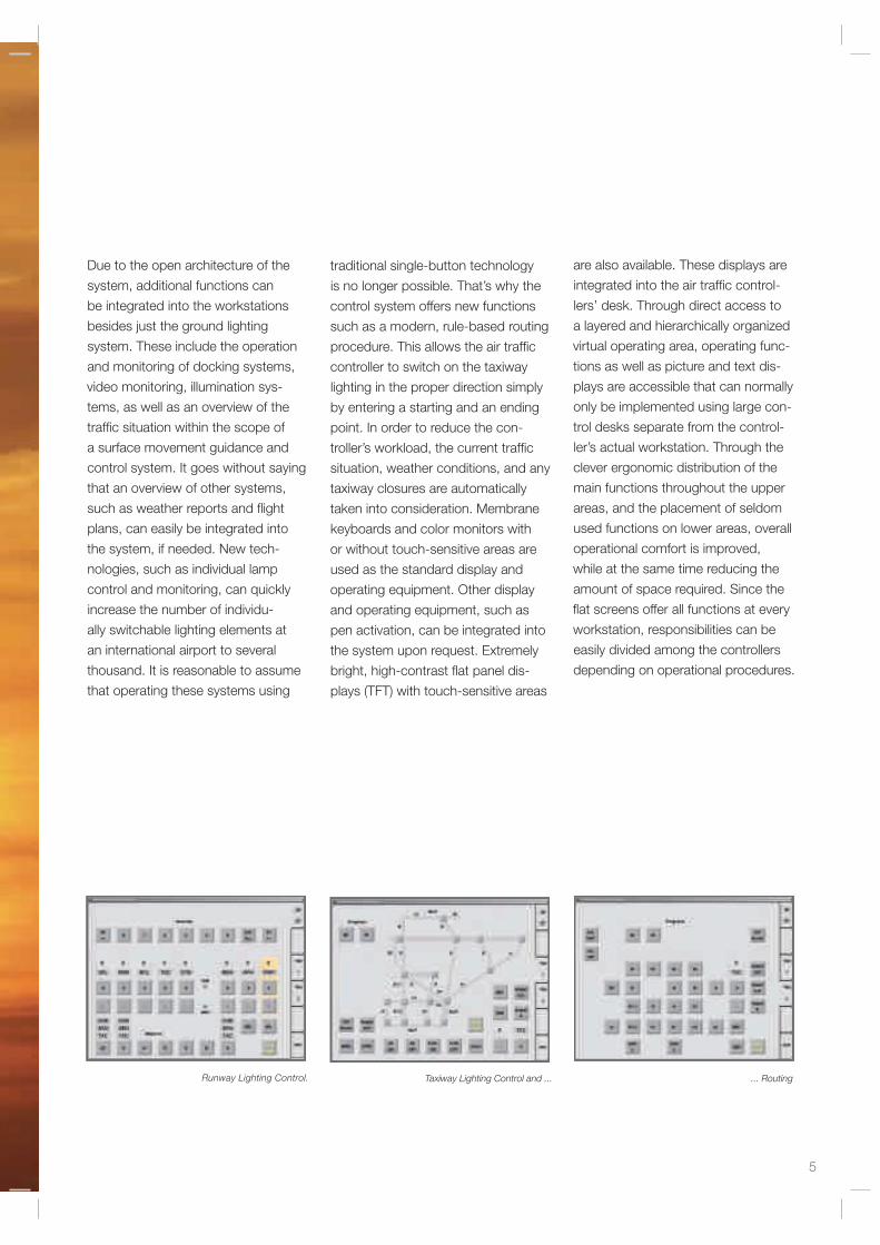
Runway Lighting Control
5
Taxiway Lighting Control and ...Runway Lighting Control.
Due to the open architecture of the
system, additional functions can
be integrated into the workstations
besides just the ground lighting
system. These include the operation
and monitoring of docking systems,
video monitoring, illumination sys-
tems, as well as an overview of the
traffic situation within the scope of
a surface movement guidance and
control system. It goes without saying
that an overview of other systems,
such as weather reports and flight
plans, can easily be integrated into
the system, if needed. New tech-
nologies, such as individual lamp
control and monitoring, can quickly
increase the number of individu-
ally switchable lighting elements at
an international airport to several
thousand. It is reasonable to assume
that operating these systems using
traditional single-button technology
is no longer possible. That’s why the
control system offers new functions
such as a modern, rule-based routing
procedure. This allows the air traffic
controller to switch on the taxiway
lighting in the proper direction simply
by entering a starting and an ending
point. In order to reduce the con-
troller’s workload, the current traffic
situation, weather conditions, and any
taxiway closures are automatically
taken into consideration. Membrane
keyboards and color monitors with
or without touch-sensitive areas are
used as the standard display and
operating equipment. Other display
and operating equipment, such as
pen activation, can be integrated into
the system upon request. Extremely
bright, high-contrast flat panel dis-
plays (TFT) with touch-sensitive areas
are also available. These displays are
integrated into the air traffic control-
lers’ desk. Through direct access to
a layered and hierarchically organized
virtual operating area, operating func-
tions as well as picture and text dis-
plays are accessible that can normally
only be implemented using large con-
trol desks separate from the control-
ler’s actual workstation. Through the
clever ergonomic distribution of the
main functions throughout the upper
areas, and the placement of seldom
used functions on lower areas, overall
operational comfort is improved,
while at the same time reducing the
amount of space required. Since the
flat screens offer all functions at every
workstation, responsibilities can be
easily divided among the controllers
depending on operational procedures.
... Routing

6
Technical Workstations
In contrast to the operationally
oriented workstations for air traffic
controllers in the tower, the technical
workstations show all the technical
details of both the lighting system and
the control and monitoring system.
Using a navigational system which is
easy to operate, even large amounts
of information can be displayed
quickly and clearly. For example,
when a particular lighting station is
selected, all information regarding the
control units and lamps installed in
that station is displayed.
Error messages from all levels are
automatically shown on the upper
control level in a summarized display.
The navigator also allows the lighting
system to be controlled at the circuit
or individual lamp level.

As an option, technical workstations
can be equipped with a scaled airport
map which includes all additional sta-
tus displays. With this option, all failed
lamps are shown on the map using
the individual lamp monitoring system.
Adjacent failed lamps are marked in
a particular way that enables easy
recognition. Detailed information can
be obtained by selecting individual
areas of the map. The functions
of the technical workstations also
include printing out reports or saving
them to a hard disk, report analy-
sis, and generation of lists. Mobile
technical workstations are also avail-
able. All workstations are equipped
with an extensive, context-sensitive
help system. The display can eas-
ily be adapted to most languages.

���SeriesCircuit Coupler
���AddressableSwitchDevicer
�����������������������
���Lamp Control and Monitoring
���
���Interface (TCP/IPoder Parallel I/O)
���Local ControlUnit (Optional)
8
Individual Lamp Control and MonitoringIndividual Lamp Control and Monitoring
Signifi cant benefi ts result from the
complete integration of Honeywell’s
individual lamp control and monitor-
ing system.
These include the dynamic, rapid
control of lighting segments and stop
bars in a manner suited to traffi c
conditions for the purposes of traffi c
COMPLETE FLEXIBILITY OF CONTROL
SCENARIOS FOR THE GROUND LIGHTING
SYSTEM.
THE SYSTEM MAKES IT POSSIBLE TO
GUIDE AIRCRAFT USING THE GROUND
LIGHTING SYSTEM WITHIN THE SCOPE OF
A SURFACE MOVEMENT GUIDANCE AND
CONTROL SYSTEM.
DETECTION OF ERRORS IN
ADJACENT LIGHTING UNITS.
SUPPORT FOR PREVENTATIVE
MAINTENANCE.
routing as part of a modern surface
movement guidance and control sys-
tem. Another notable benefi t is the
automatic reporting of adjacent lamp
failures under consideration of the
operational rather than spatial
relationships as an example of the
intelligent data processing which
occurs during monitoring. In addition,
the conditions, errors, and running
times of all lamps are monitored by
system and recorded in its database.

99
Controlling all lamp groups
and switching scenarios.
Powerful local control for the
control and monitoring of lamps
from all technical workstations.
Transfer of all monitoring results
from individual lamp monitoring.
Display of all lamp failures on a
scaled airport map.
Configuring the individual lamp
control system and the individual
lamp control module can be carried
out comfortably in the control system
and is downloaded automatically, if
needed. This means that the auto-
matic configuration of each unit is
backed up using the series circuit
even after replacing switching
modules in the field.
In connection with the Honeywell
Control and Monitoring System, the
following functions are supported:
Display of adjacent lamp failures.
Operating hours counter for eight
operating levels per lamp.
Creating configuration data with
automatic downloading to the
switching units.

10
Monitoring Functions
Through comprehensive monitoring
of the lighting and control systems,
maintenance personnel receive early
warning of any technical problems.
This allows them to promptly begin
maintenance work and avoid system
malfunctions. The system contains
the following monitoring functions:
�� Determination of the present
switching status of the constant
current regulators, plug-in
switch units, and pulse
generators, and a comparison
with their preset switching status.
�� Registration of the local
operation of the constant
current regulators, plug-in
switch units, and pulse
generators.
�� Recording the operating
hours of each lighting circuit
and each individual lamp.
Operating hours are recorded in real
time and are divided into a maximum
of eight operating levels (power rates)
for each lighting circuit. An assess-
ment of the entire system is carried
out and an alert is sent when peak
levels are reached. An additional
assessment can be carried out using
weighted or unweighted values.
�� Lamp failure monitoring for each
individual lamp or per circuit.
The threshold levels for alarms
can be freely configured. In the
individual lamp monitoring
system, the failure location and
the failure of adjacent lamps are
also reported.
�� Monitoring of the lighting circuits’
insulation. The threshold levels
for alarms can be freely configured
for each lighting circuit.
�� Calculation of the series
circuit current and display of
each circuit’s current value.
�� Monitoring of all integrated
equipment and data transmission
routes within the control and
monitoring system.
The following information is recorded
and archived in the sequential log file:
�� Technical malfunctions
in the lighting system
�� Changes to insulation values
�� Lamp failures
�� Changes to the configuration,
for example, to threshold values
�� Switching actions
�� Technical malfunctions in the
control system

11
Station EquipmentFrom the perspective of prevent-
ing malfunctions, in previous control
systems activating the controllers was
a critical point. In order to solve this
problem we developed a new, redun-
dant interface concept for the current
version of our control and monitoring
system, which limits a malfunction to
a maximum of one circuit. Through
the proven use of locking relays
as output components, random
changes to the lighting system are
effectively prevented. The interface
concept also supports conventional
parallel interfaces between the control
system and the controllers. This en-
sures that all types of controllers can
be connected to the system. Besides
the parallel interface, the control and
monitoring system also provides a se-
rial interface for controllers connected
using TCP/IP and Ethernet proto-
cols. In order to maintain the ground
lighting system, the system makes all
information regarding the lighting sys-
tem available at a technical worksta-
tion located in every substation. The
workstation also allows every aspect
of the system to be controlled, right
down to controlling individual lamps.

1212
Benefits
Control and Monitoring System for Airport Ground Lighting Equipment
�� System Design
� � Scalable computer network
� � Modular design
� � Simple or fully redundant
design with identical hardware
� � Communication over standard
ETHERNET with TCP/IP
protocol
�� ���������������������
� ��������� �������
� � Scaled airport map which
provides an oveview
of traffic conditions
� � Automatic routing sytem
for taxiway lighting
� � A switching time of less
than one second from
command to execution
Operating concepts for air
traffic controller workstations
have been optimized
�� ������������ �������
� Comprehensive technical
monitoring of the lighting
system
� Full integration of individual
lamp control and monitoring
� Monitoring of insulation
� Information on series circuits
displayed at all technical
working positions
� Operating hours counted for
circuits and lamps and
classified into ratings eight
power
�� ������������ �
� Completely object-oriented
software (C++, CORBA 2)
� Highly modular design
allows for flexible distribution
within the network
� Adaptation to specific
airport requirements is carried
out using configuration lists.
� The software is independent
of the hardware platform
� HMI platform for the integration
of other subsystems

13

The system architecture of the
airport lighting control and monitor-
ing system is based on a modern,
distributed, and fully scalable
computer system.
The computers are connected over
a 10 or 100Mbit/s Ethernet (TCP/IP)
connection. Both the individual
computers as well as the network
can be duplicated in order to
increase operational security.
Fiber optic cables are preferred for
communication between buildings.
The system can also use existing
high-speed networks such as FDDI,
ATM, etc. as its backbone. PCs or
workstations can be used according
to the requirements and computing
power needed. The software is
coded in C++ in a completely object-
oriented manner. To ensure that the
software remains completely inde-
pendent of hardware and operating
systems, all software interfaces
comply with the international
CORBA standard. This makes it
possible to freely distribute the
software modules within the net-
work. The scope of the network
is determined by the needs and
performance requirements of each
project, and is not limited by the
software.
1414

The use of the CORBA standards and
TCP/IP protocols also offers an
internationally standardized interface
which allows for easy connection to
other systems such as the airport
information system (FIS) or a higher
guidance system. The Human
Machine Interfaces (HMI) are graphic
interfaces showing the airport layout
or station equipment, and are
generated using powerful tools for
process visualization. In some parts
of the system, Java is already being
used as a platform-independent
programming language. The actual
adaptation of the system to the
needs of individual airports is carried
out using confi guration fi les (in the
form of Microsoft Excel fi les). These
confi guration fi les contain all the
individual characteristics of the
system and the lighting equipment;
and upon fi rst starting the system,
they automatically generate the actual
operational program based on the
existing object class library. The
system is equipped with comprehen-
sive software for ongoing self diag-
nostics. If required, an online diag-
nostics program is available via the
remote data-transfer interface.
This interface is also used for changes
to the confi guration and software.
1515

www.honeywell.de/airportsystems
!������������"������������#�$!Industriestrasse 23-3322880 WedelGermany
Technical data and fi gures are for informational purposes only. We reserve the right to make changesto this information at any time. Updated: 09/2009© 2009 Honeywell Airport Systems GmbH
www.climatepartner.com932-53266-0909-1001
Honeywell Building Solutions GmbHAirports BusinessBrödermannsweg 122453 HamburgGermanyTel: +49 (0) 40 61144-0Fax: +49 (0) 40 61144-06
www.honeywellairports.com