Grounding and Bonding of Service Equipment
38
8/5/2018 1 EXCHANGING EXPERTISE SINCE 1893 NWEMS Grounding and Bonding of Service Equipment 3/27/2018 | NW Electrical Meter School | Track D – Grounding and Bonding of Meters | Chuck Matsen, Seattle City Light EXCHANGING EXPERTISE SINCE 1893 » NEC 250.4 – 1. Grounding: • Electrical Systems that are grounded shall be connected to earth in a manner that will limit the voltage imposed by lightning, line surges, or unintentional contact with higher‐voltage lines and that will stabilized the voltage to earth during normal operation. – 2. Grounding: • Non‐current carrying conductive materials enclosing electrical conductors or equipment, or forming part of such equipment shall be connected to earth so as to limit the voltage to ground on these materials. – 3. Bonding: • Non‐current carrying conductive materials enclosing electrical conductors or equipment, or forming part of such equipment, shall be connected together and to the electrical supply source in a manner that establishes an effective ground‐fault current path. 2 1. Grounding means: “attached to an earth ground”. 2. Bonding means: “physically connected to insure electrical continuity”.
Transcript of Grounding and Bonding of Service Equipment

8/5/2018
1
EXCHANGING EXPERTISE SINCE 1893
NWEMS
Grounding and Bonding of Service Equipment
3/27/2018 | NW Electrical Meter School | Track D – Grounding and Bonding of Meters | Chuck Matsen, Seattle City Light
EXCHANGING EXPERTISE SINCE 1893
» NEC 250.4
– 1. Grounding:
• Electrical Systems that are grounded shall be connected to earth in a manner that will limit the voltage imposed by lightning, line surges, or unintentional contact with higher‐voltage lines and that will stabilized the voltage to earth during normal operation.
– 2. Grounding:
• Non‐current carrying conductive materials enclosing electrical conductors or equipment, or forming part of such equipment shall be connected to earth so as to limit the voltage to ground on these materials.
– 3. Bonding:
• Non‐current carrying conductive materials enclosing electrical conductors or equipment, or forming part of such equipment, shall be connected together and to the electrical supply source in a manner that establishes an effective ground‐fault current path.
2
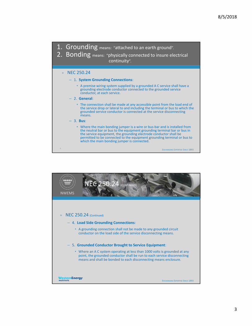
1. Grounding means: “attached to an earth ground”.
2. Bonding means: “physically connected to insure electrical continuity”.
8/5/2018
2
EXCHANGING EXPERTISE SINCE 1893
NWEMS
NEC 250.4 (CONTINUED)
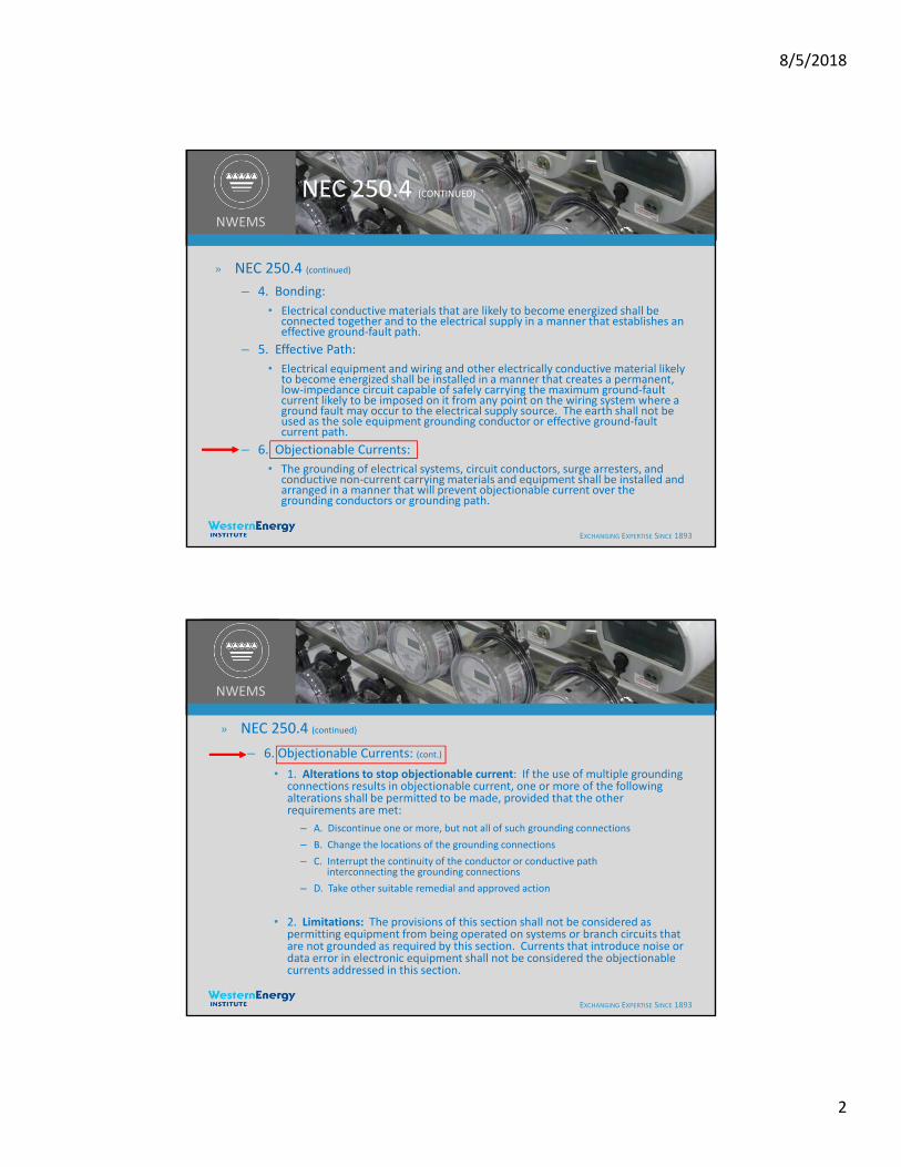
» NEC 250.4 (continued)
– 4. Bonding:
• Electrical conductive materials that are likely to become energized shall be connected together and to the electrical supply in a manner that establishes an effective ground‐fault path.
– 5. Effective Path:
• Electrical equipment and wiring and other electrically conductive material likely to become energized shall be installed in a manner that creates a permanent, low‐impedance circuit capable of safely carrying the maximum ground‐fault current likely to be imposed on it from any point on the wiring system where a ground fault may occur to the electrical supply source. The earth shall not be used as the sole equipment grounding conductor or effective ground‐fault current path.
– 6. Objectionable Currents:
• The grounding of electrical systems, circuit conductors, surge arresters, and conductive non‐current carrying materials and equipment shall be installed and arranged in a manner that will prevent objectionable current over the grounding conductors or grounding path.
EXCHANGING EXPERTISE SINCE 1893
NWEMS
» NEC 250.4 (continued)
– 6. Objectionable Currents: (cont.)
• 1. Alterations to stop objectionable current: If the use of multiple grounding connections results in objectionable current, one or more of the following alterations shall be permitted to be made, provided that the other requirements are met:
– A. Discontinue one or more, but not all of such grounding connections
– B. Change the locations of the grounding connections
– C. Interrupt the continuity of the conductor or conductive path interconnecting the grounding connections
– D. Take other suitable remedial and approved action
• 2. Limitations: The provisions of this section shall not be considered as permitting equipment from being operated on systems or branch circuits that are not grounded as required by this section. Currents that introduce noise or data error in electronic equipment shall not be considered the objectionable currents addressed in this section.
8/5/2018
3
EXCHANGING EXPERTISE SINCE 1893
» NEC 250.24
– 1. System Grounding Connections:
• A premise wiring system supplied by a grounded A C service shall have a grounding electrode conductor connected to the grounded service conductor, at each service.
– 2. General:
• The connection shall be made at any accessible point from the load end of the service drop or lateral to and including the terminal or bus to which the grounded service conductor is connected at the service disconnecting means.
– 3. Bus:
• Where the main bonding jumper is a wire or bus‐bar and is installed from the neutral bar or bus to the equipment grounding terminal bar or bus in the service equipment, the grounding electrode conductor shall be permitted to be connected to the equipment grounding terminal or bus to which the main bonding jumper is connected.
5
1. Grounding means: “attached to an earth ground”.
2. Bonding means: “physically connected to insure electrical continuity”.
EXCHANGING EXPERTISE SINCE 1893
NWEMS
NEC 250.24 (CONTINUED)
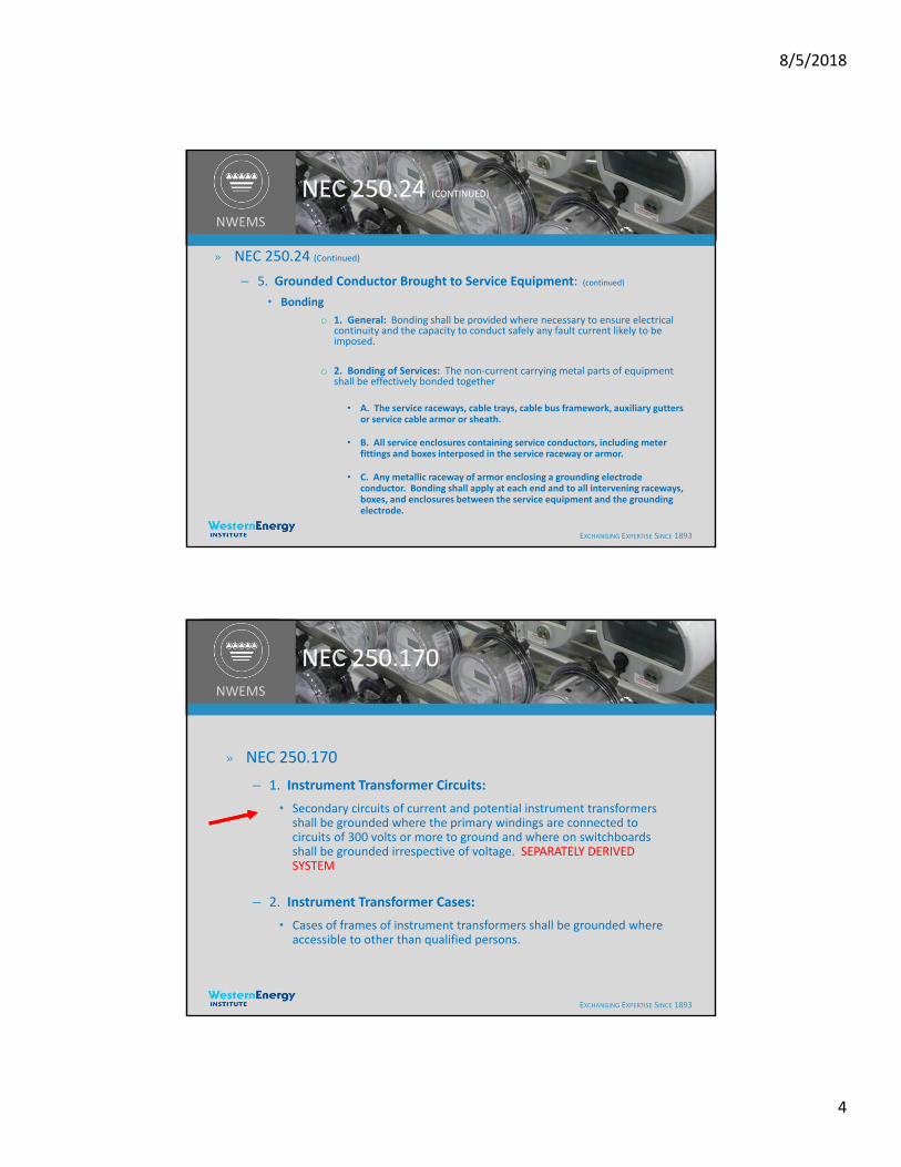
» NEC 250.24 (Continued)
– 4. Load Side Grounding Connections:
• A grounding connection shall not be made to any grounded circuit conductor on the load side of the service disconnecting means.
– 5. Grounded Conductor Brought to Service Equipment:
• Where an A C system operating at less than 1000 volts is grounded at any point, the grounded conductor shall be run to each service disconnecting means and shall be bonded to each disconnecting means enclosure.
8/5/2018
4
EXCHANGING EXPERTISE SINCE 1893
NWEMS
NEC 250.24 (CONTINUED)
» NEC 250.24 (Continued)
– 5. Grounded Conductor Brought to Service Equipment: (continued)
• Bonding
o 1. General: Bonding shall be provided where necessary to ensure electrical continuity and the capacity to conduct safely any fault current likely to be imposed.
o 2. Bonding of Services: The non‐current carrying metal parts of equipment shall be effectively bonded together
• A. The service raceways, cable trays, cable bus framework, auxiliary gutters or service cable armor or sheath.
• B. All service enclosures containing service conductors, including meter fittings and boxes interposed in the service raceway or armor.
• C. Any metallic raceway of armor enclosing a grounding electrode conductor. Bonding shall apply at each end and to all intervening raceways, boxes, and enclosures between the service equipment and the grounding electrode.
EXCHANGING EXPERTISE SINCE 1893
NWEMS
NEC 250.170
» NEC 250.170
– 1. Instrument Transformer Circuits:
• Secondary circuits of current and potential instrument transformers shall be grounded where the primary windings are connected to circuits of 300 volts or more to ground and where on switchboards shall be grounded irrespective of voltage. SEPARATELY DERIVED SYSTEM
– 2. Instrument Transformer Cases:
• Cases of frames of instrument transformers shall be grounded where accessible to other than qualified persons.

8/5/2018
5
EXCHANGING EXPERTISE SINCE 1893
NWEMS
NEC 250.170 (CONTINUED)
» NEC 250.170 (Continued)
– 3. Cases of Instruments, Meters, and Relays operating at less than 1000 volts:
• Instruments, meters, and relays operating with winding or working parts at less than 1000 volts shall be grounded.
– 4. Instrument Grounding Conductor:
• The grounding conductor for secondary circuits of instrument transformers and for instrument cases shall not be smaller than #12 copper or #10 aluminum. Cases of instrument transformers, instruments, meters, and relays that are mounted directly on grounded metal surfaces of enclosures or grounded metal switchboard panels shall be considered to be grounded and no additional grounding conductor shall be required.
EXCHANGING EXPERTISE SINCE 1893
NWEMS
Grounding electrodeConductor
A B N
G
Grounding electrode: Gnd Rod, WP, Ufer, Bldg Steel, etc
Main Bonding Jumper
Grounded Conductor
Grounding Conductor
Pole Ground(if it hasn’t been stolen)
8/5/2018
6
11
MAIN
N
L1 L2
Typical Self Contained Installation
Bonding Jumper
Bond
W 1
W 2
W 3
12
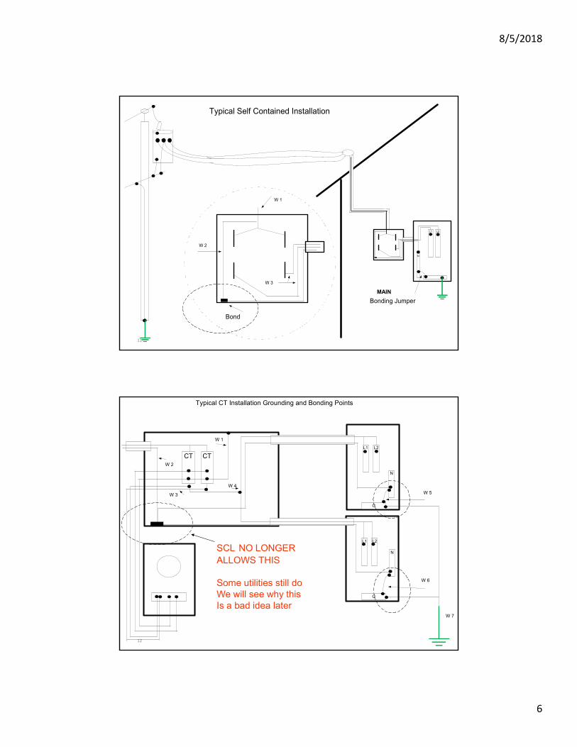
SCL NO LONGERALLOWS THIS
Some utilities still doWe will see why thisIs a bad idea later
L1 L2
L1 L2
N
N
G
G
CT CT
Typical CT Installation Grounding and Bonding Points
W 1
W 2
W 3
W 4
W 5
W 6
W 7

8/5/2018
7
13
CT 1 CT2 CT 3
N
G
Typical Switchboard Installation
W 1
W 2
W 4
W 3
W 5
W 6
W 8
W 7 W 9
W 10
W 11
W 12
EXCHANGING EXPERTISE SINCE 1893
NWEMS
Ground Loops6/13/2016

8/5/2018
8
EXCHANGING EXPERTISE SINCE 1893
NWEMS
What is the name of the “grounded conductor” in an electrical circuit?
What color is it?
What is it’s function?
EXCHANGING EXPERTISE SINCE 1893
NWEMS
What is the name of the “grounding conductor” in an electrical circuit?
What color is it?
What is it’s function?

8/5/2018
9
EXCHANGING EXPERTISE SINCE 1893
NWEMS
A ground loop exists when an electrical system is connected with multiple paths to ground
When two or more devices are connected to a common ground through different paths a ground loop occurs
18
A Designed Ground Loop
VM
Water Meter
Ground Step Potential Gradient

8/5/2018
10
19
A B N
G
A Problem Ground Loop
VM VM
EXCHANGING EXPERTISE SINCE 1893
NWEMS
Currents flow through these multiple paths and develop voltages that can damage sensitive equipment, cause noise, and affect meter readings which offset from actual values
8/5/2018
11
EXCHANGING EXPERTISE SINCE 1893
NWEMS
They can cause indicating meters to “peg up” or “peg down” and/or lock up
They can cause sensitive electronic equipment to be inaccurate or even fail
EXCHANGING EXPERTISE SINCE 1893
NWEMS
NEC defines a ground as a conducting connection between an electrical circuit and earth
A ground loop can be defined as objectionable current flowing in that ground or return path

8/5/2018
12
EXCHANGING EXPERTISE SINCE 1893
NWEMS
The simplest ground loop involves a connection between two different earth grounds
24
VM
Panel
Water Pipe
HigherLower
L1
N
G
VM

8/5/2018
13
EXCHANGING EXPERTISE SINCE 1893
NWEMS
Even though NEC requires grounding electrodes and metal parts to be bonded together, there will still be differences in ground potentials in most systems
EXCHANGING EXPERTISE SINCE 1893
NWEMS
One common cause of ground loops is double bonding of the “grounded conductor”
NEC requires the neutral to be bonded to ground at only oneplace, at the source entrance or first disconnect

8/5/2018
14
EXCHANGING EXPERTISE SINCE 1893
NWEMS
When the neutral is double bonded, returning neutral current will split per Kirchhoff's law and flow in the ground circuit
This current can cause varying voltage references to equipment in the circuit such as metering
28
Panel L1
N
G
VM
VM
8/5/2018
15
EXCHANGING EXPERTISE SINCE 1893
NWEMS
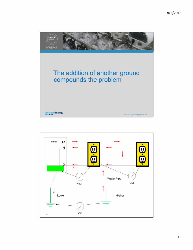
The addition of another ground compounds the problem
30
Panel
Water Pipe
HigherLower
L1
N
G
VM
VMVM
8/5/2018
16
EXCHANGING EXPERTISE SINCE 1893
NWEMS
Solving ground loop problems is a two-fold process
EXCHANGING EXPERTISE SINCE 1893
NWEMS
#1 Remove multiple paths to ground

8/5/2018
17
EXCHANGING EXPERTISE SINCE 1893
NWEMS
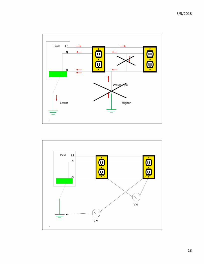
#2 Remove multiple neutral to ground bonds
EXCHANGING EXPERTISE SINCE 1893
NWEMS
With these two easy steps,
ground loops will be eliminated
8/5/2018
18
35
Panel
Water Pipe
HigherLower
L1
N
G
36
Panel L1
N
G
VM
VM

8/5/2018
19
EXCHANGING EXPERTISE SINCE 1893
NWEMS
Metering circuits that contain ground loops can have measurement errors
The measurement errors will be proportional to the voltage drop in the metering potential circuit caused by current in the neutral conductor
The measurement error will always be a net loss for the utility
38
• AC Calculation for Ground Loop Loss• Voltage: 120 V
• Load: 1200 Amps (300/5 CT’s)
• Load Circuit: 3-PH, 4-W Wye
• Power Factor: 1 (for this example)
• Insulation Temp: 75°C/167°F
• Conductor: Copper
• Conductors per Phase: 1
• Conduit: Aluminum
• Cable Length: 75 Feet
• Conductor Gauge: 12
• Observed in field:• 1.20 Volts Line-to-
Neutral voltage drop = 118.8 Volts at the 9S meter socket
8/5/2018
20
EXCHANGING EXPERTISE SINCE 1893 39
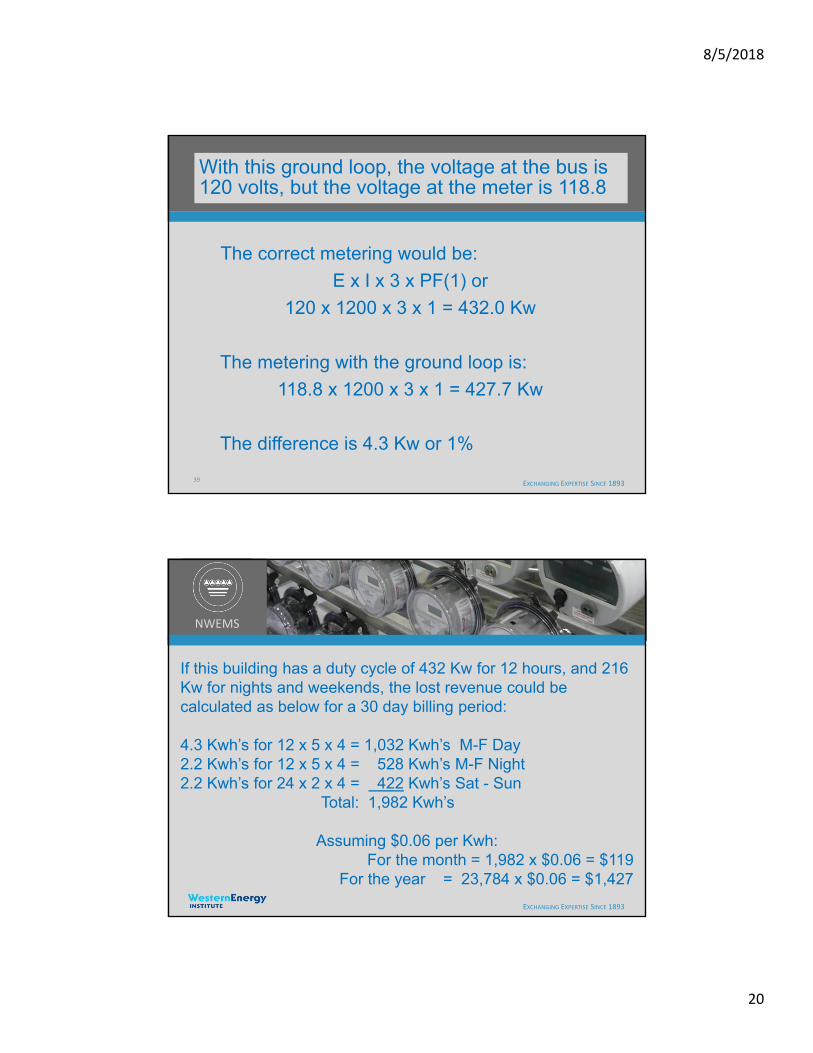
With this ground loop, the voltage at the bus is 120 volts, but the voltage at the meter is 118.8
The correct metering would be:
E x I x 3 x PF(1) or
120 x 1200 x 3 x 1 = 432.0 Kw
The metering with the ground loop is:
118.8 x 1200 x 3 x 1 = 427.7 Kw
The difference is 4.3 Kw or 1%
EXCHANGING EXPERTISE SINCE 1893
NWEMS
If this building has a duty cycle of 432 Kw for 12 hours, and 216 Kw for nights and weekends, the lost revenue could be calculated as below for a 30 day billing period:
4.3 Kwh’s for 12 x 5 x 4 = 1,032 Kwh’s M-F Day2.2 Kwh’s for 12 x 5 x 4 = 528 Kwh’s M-F Night2.2 Kwh’s for 24 x 2 x 4 = 422 Kwh’s Sat - Sun
Total: 1,982 Kwh’s
Assuming $0.06 per Kwh:For the month = 1,982 x $0.06 = $119
For the year = 23,784 x $0.06 = $1,427
8/5/2018
21
EXCHANGING EXPERTISE SINCE 1893
NWEMS
Our Utility has 420,000 accounts with 43,000 CT services
Each CT service is undergoing an electrical Audit to insure the integrity of our metering systems
EXCHANGING EXPERTISE SINCE 1893
NWEMS
Our Utility has instituted steps to eliminate all ground loops from new and existing service installations
8/5/2018
22
EXCHANGING EXPERTISE SINCE 1893
NWEMS
How can you determine if you have a ground loop condition on your metering system ?
1. Measure for current on the neutral at the test switch
2. Measure for a difference in potential between the bus and the test switch
If either of these conditions is true, you probably have a ground loop
EXCHANGING EXPERTISE SINCE 1893
NWEMS
If you find either of these conditions, you will find a ground loop
Clear your ground loop and retake your measurements
Once your ground loop is cleared, your measurements will return to normal levels
(very small current - and - bus voltage will match test switch voltage)

8/5/2018
23
45
TS
CT CT CT
A CB
N
= Bonded to Ground
= Neutral
ABC N
GROUND CURRENT
NEUTRAL CURRENT
46
TS
CT CT CT
A CB
N
= Bonded to Ground
= Neutral
VM2
VM1 and VM2 are unequal
VM1
119120
ABC N
JUMPER AT TESTSWITCH CAUSINGA GROUND LOOP
GROUND CURRENT
NEUTRAL CURRENT
8/5/2018
24
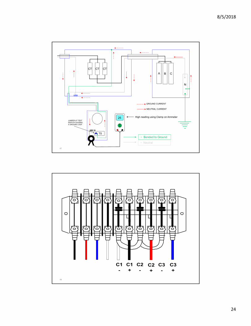
47
TS
CT CT CT
A CB
N
= Bonded to Ground
= Neutral
ABC N
25 High reading using Clamp on AmmeterJUMPER AT TESTSWITCH CAUSINGA GROUND LOOP
GROUND CURRENT
NEUTRAL CURRENT
48
C1-
C1+
C2-
C2+
C3+
C3-
8/5/2018
25
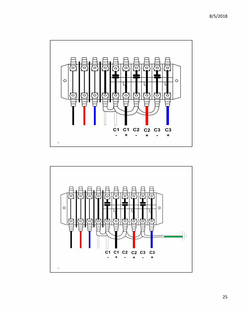
49
C1-
C1+
C2-
C2+
C3+
C3-
50
C1-
C1+
C2-
C2+
C3+
C3-

8/5/2018
26
51
C1
-
C1
+
C2
-
C2
+
C3
+
C3
-
52
-C1+
C2-
C2+
C3+
C3-
C1
Most desirable Means

8/5/2018
27
53
C1-
C1+
C2-
C2+
C3+
C3-
1 2 3N
54
C1-
C1+
C2-
C2+
C3+
C3-
8/5/2018
28
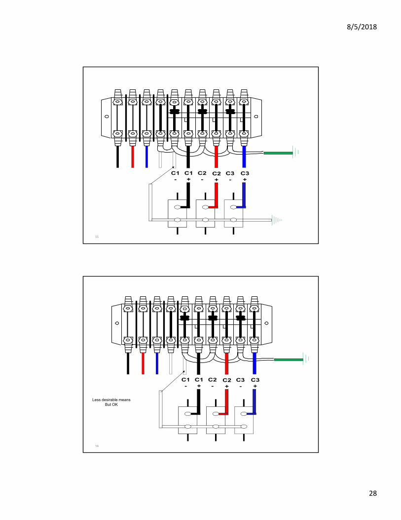
55
C1-
C1+
C2-
C2+
C3+
C3-
56
C1-
C1+
C2-
C2+
C3+
C3-
Less desirable meansBut OK
8/5/2018
29
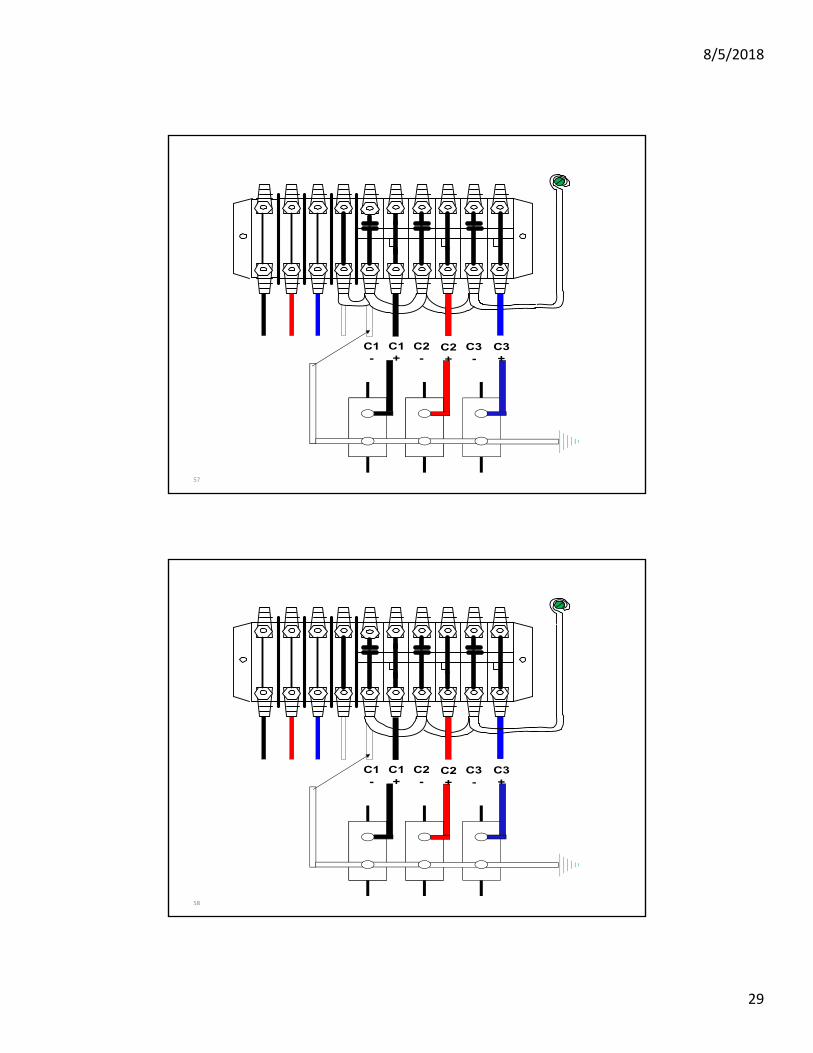
57
C1-
C1+
C2-
C2+
C3+
C3-
58
C1-
C1+
C2-
C2+
C3+
C3-
8/5/2018
30
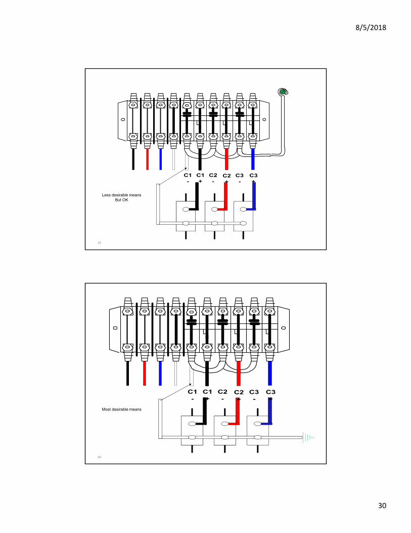
59
C1-
C1+
C2-
C2+
C3+
C3-
Less desirable meansBut OK
60
C1-
C1+
C2-
C2+
C3+
C3-
Most desirable means

8/5/2018
31
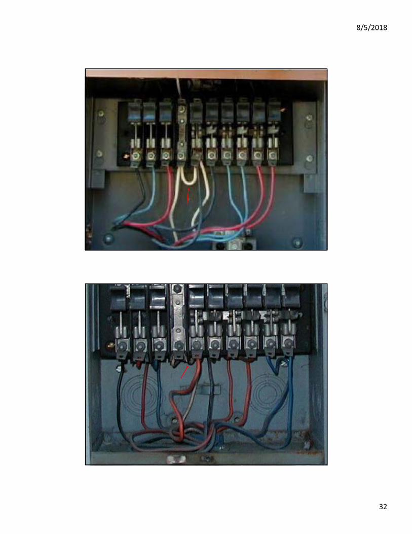
61
62
8/5/2018
32
63
64

8/5/2018
33
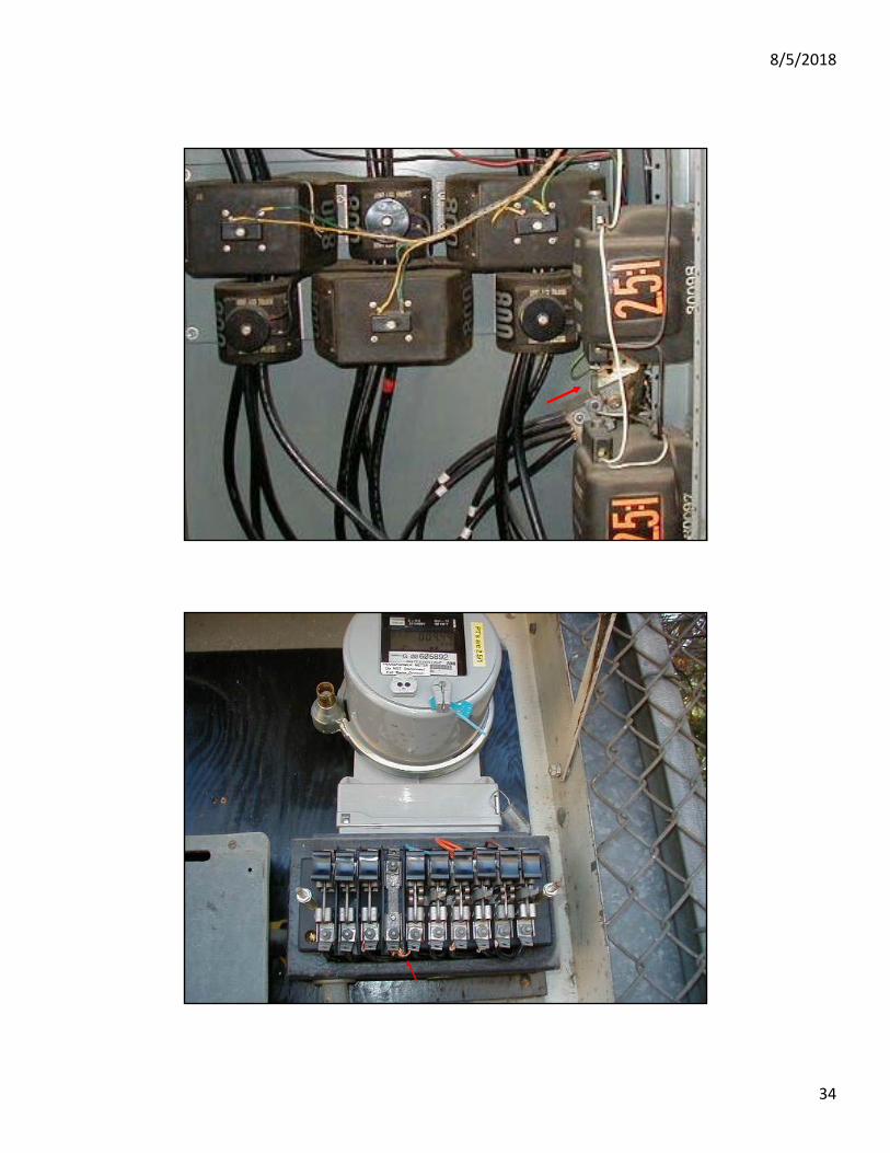
65
EXCHANGING EXPERTISE SINCE 1893 66
8/5/2018
34
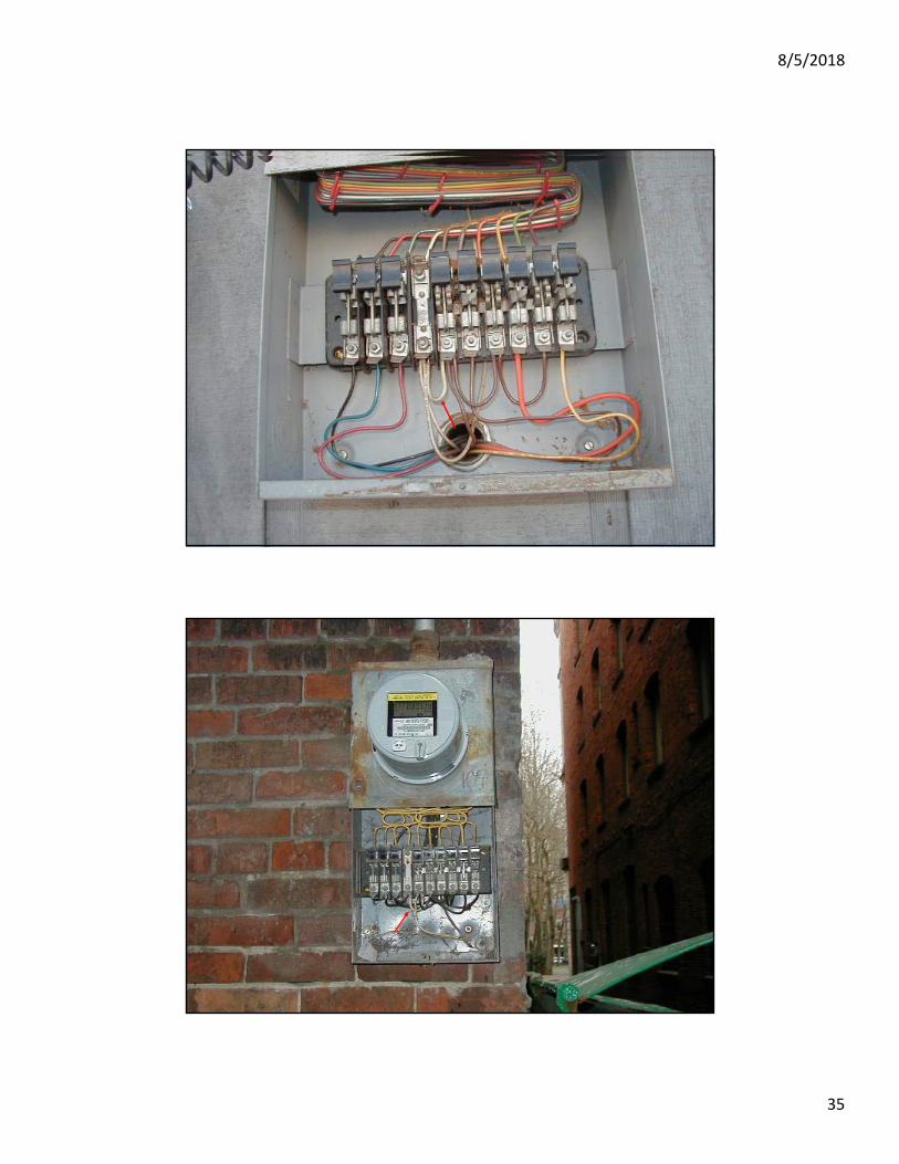
67
68
8/5/2018
35
69
70

8/5/2018
36
71
72
8/5/2018
37
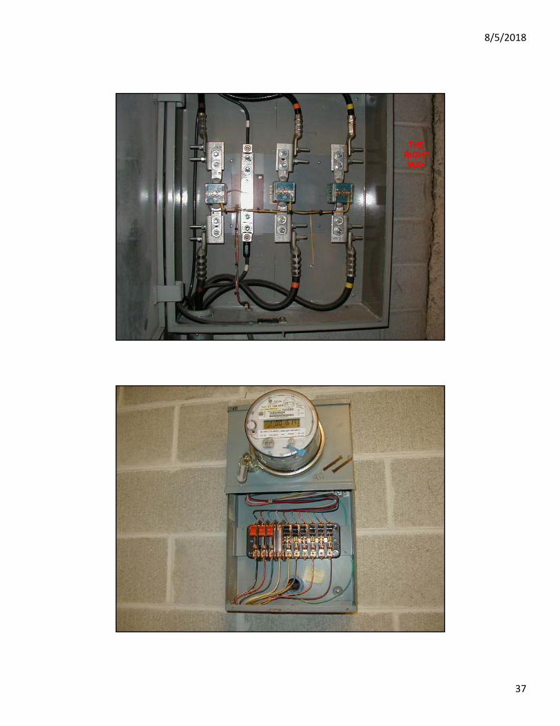
73
THERIGHTWAY
74
8/5/2018
38
EXCHANGING EXPERTISE SINCE 1893
NWEMS