Ground Works Plan
4
A - A 112 ( SVP ) 150 350 150 150 350 150 150 350 150 2235 1797.5 2147.5 2935 Existing inspection chamber NEW FWIC CL = Ground Level IL = To Suit Falls Proposed Storm water to be connected into existing storm gulley Proposed Storm water to be connected into existing storm gulley SITE PREPARATION Ground to be prepared for new works by removing all unsuitable material, vegetable matter and tree or shrub roots to a suitable depth to prevent future growth. Seal up, cap off, disconnect and remove existing redundant services as necessary. Reasonable precautions must also be taken to avoid danger to health and safety caused by contaminants and ground gases e.g. landfill gases, radon, vapours etc. on or in the ground covered, or to be covered by the building. FLOOR CONSTRUCTION - SOLID FLOOR INSULATION OVER SLAB Solid ground floor to consist of 250mm consolidated well - rammed hardcore. Blinded with 50mm sand blinding. Provide 125mm ST2 or Gen2 ground bearing slab concrete mix to conform to BS 8500 - 2 over a 1200 gauge polythene DPM. DPM to be lapped in with DPC in walls. Floor to be insulated over slab and DPM with 150mm thick Celotex FR5000. 25mm insulation to continue around floor perimeters to avoid thermal bridging. A VCL should be laid over the insulation boards and turned up 100mm at room perimeters behind the skirting, all joints to be lapped 150mm and sealed. Finish with 65mm sand/cement finishing screed with light mesh reinforcement. Where drain runs pass under new floor, provide A142 mesh 1.0m wide and min 50mm concrete cover over length of drain. Where existing suspended timber floor air bricks are covered by new extension, ensure cross - ventilation is maintained by connecting to 100mm dia UPVC pipes with 100mm concrete cover laid under the extension. Pipes to terminate at new 65mm x 215mm air bricks with cavity tray over. U Value of 0.15W/m²K Care to be taken when excavating existing floor not to undermine existing foundations. EXISTING STRUCTURE Existing structure including foundations, beams, walls and lintels carrying new and altered loads are to be exposed and checked for adequacy prior to commencement of work and as required by the Building Control Officer. EXISTING STRUCTURE Existing structure including foundations, beams, walls and lintels carrying new and altered loads are to be exposed and checked for adequacy prior to commencement of work and as required by the Building Control Officer. STRIP FOUNDATION Provide 225mm x 650mm concrete foundation, concrete mix to conform to BS EN 206 - 1 and BS 8500 - 2. All foundations to be agreed on site with Building Control Officer to suit site conditions. All constructed in accordance with 2010 Building Regulations A1/2 and BS 8004:1986 Code of Practice for Foundations. Ensure foundations are constructed below invert level of any adjacent drains. Base of foundations supporting internal walls to be min 600mm below ground level. Sulphate resistant cement to be used if required. Please note that should any adverse soil conditions be found or any major tree roots in excavations, the Building Control Officer is to be contacted and the advice of a structural engineer should be sought. PIPES PASSING THROUGH WALLS Walls above pipes passing through substructure walls to be supported on suitable lintel on semi - engineering bricks. Pipe to be provided with a 50mm clearance all round, opening to be masked with granular backfill (pea shingle) around pipe. DPC to be provided as required by BCO. WALLS BELOW GROUND All new walls to have Class A blockwork below ground in 1:4 masonry cement or equal approved specification. Cavities below ground level to be filled with lean mix concrete min 225mm below damp proof course. Or provide lean mix backfill at base of cavity wall (150mm below damp course) laid to fall to weepholes. UNDERGROUND FOUL DRAINAGE Underground drainage to consist of 100mm diameter UPVC proprietary pipe work to give a 1:40 fall. Surround pipes in 100mm pea shingle. Provide 600mm suitable cover (900mm under drives). Shallow pipes to be covered with 100mm reinforced concrete slab over compressible material. Provide rodding access at all changes of direction and junctions. All below ground drainage to comply with BS EN 1401 - 1. INSPECTION CHAMBERS Underground quality proprietary UPVC 450mm diameter inspection chambers to be provided at all changes of level, direction, connections and every 45m in straight runs. Inspection chambers to have bolt down double sealed covers in buildings and be adequate for vehicle loads in driveways. ACO Drain Head Office 29 Broad Street Newtown Powys t - 01686 610311 w - www.hughesarchitects.co.uk Drawing No :- Drawn by :- Scale :- Date :- Checked :- Rev :- Drawing Status :- Project :- Drawing Title :- This drawing is COPYRIGHT. It must not be reproduced or disclosed to third parties without our prior permission. Do not from this drawing, or, interrogate and use electronic information. Any discrepancies should be reported immediately. Any surveyed information incorporated within this drawing cannot be guaranteed as accurate unless confirmed by a fixed dimension. All dimensions are in millimetres unless noted otherwise. 1 : 20 C Side Extension to Kerry Public Conveniences, Kerry, Powys Ground Works Plan RL HB 25.05.21 Stage 3b ( Building Regs ) V093.3b. 1.110 C - HB - Updated following KCC meeting - 15.09.21 1 : 20 Ground Works Plan
Transcript of Ground Works Plan
A - A
112
( SVP )
150 350 150
150
350
150
150
350
150
2235
1797.5
2147.5
2935
Existing inspection chamber
NEW FWIC
CL = Ground LevelIL = To Suit Falls
Proposed Storm water to be connected into existing storm gulley
Proposed Storm water to be connected into existing
storm gulley
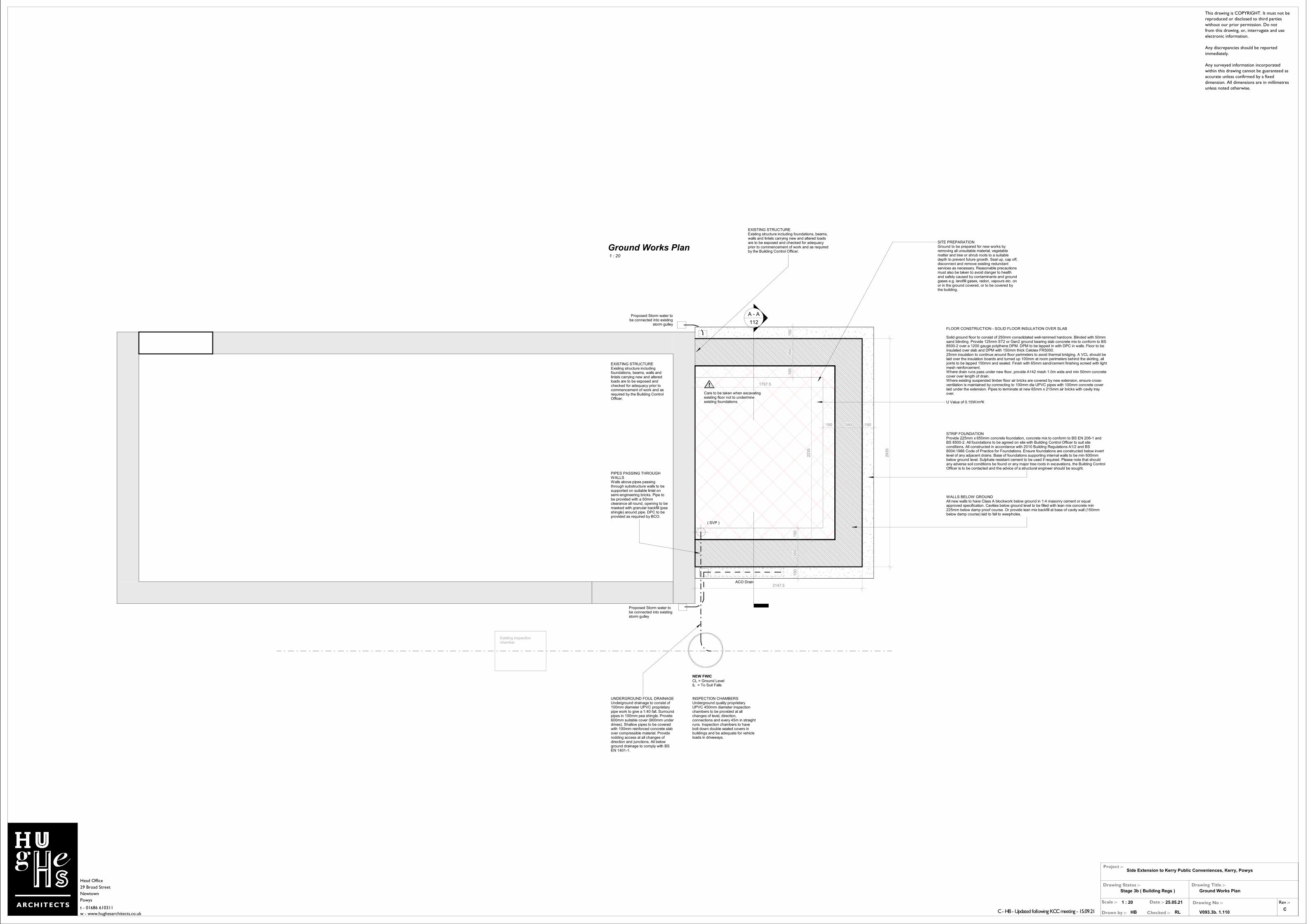
SITE PREPARATIONGround to be prepared for new works by removing all unsuitable material, vegetable matter and tree or shrub roots to a suitable depth to prevent future growth. Seal up, cap off, disconnect and remove existing redundant services as necessary. Reasonable precautions must also be taken to avoid danger to health and safety caused by contaminants and ground gases e.g. landfill gases, radon, vapours etc. on or in the ground covered, or to be covered by the building.
FLOOR CONSTRUCTION - SOLID FLOOR INSULATION OVER SLAB
Solid ground floor to consist of 250mm consolidated well-rammed hardcore. Blinded with 50mm sand blinding. Provide 125mm ST2 or Gen2 ground bearing slab concrete mix to conform to BS 8500-2 over a 1200 gauge polythene DPM. DPM to be lapped in with DPC in walls. Floor to be insulated over slab and DPM with 150mm thick Celotex FR5000. 25mm insulation to continue around floor perimeters to avoid thermal bridging. A VCL should be laid over the insulation boards and turned up 100mm at room perimeters behind the skirting, all joints to be lapped 150mm and sealed. Finish with 65mm sand/cement finishing screed with light mesh reinforcement. Where drain runs pass under new floor, provide A142 mesh 1.0m wide and min 50mm concrete cover over length of drain.Where existing suspended timber floor air bricks are covered by new extension, ensure cross-ventilation is maintained by connecting to 100mm dia UPVC pipes with 100mm concrete cover laid under the extension. Pipes to terminate at new 65mm x 215mm air bricks with cavity tray over.
U Value of 0.15W/m²K
Care to be taken when excavating existing floor not to undermine existing foundations.
EXISTING STRUCTUREExisting structure including foundations, beams, walls and lintels carrying new and altered loads are to be exposed and checked for adequacy prior to commencement of work and as required by the Building Control Officer.
EXISTING STRUCTUREExisting structure including foundations, beams, walls and lintels carrying new and altered loads are to be exposed and checked for adequacy prior to commencement of work and as required by the Building Control Officer.
STRIP FOUNDATIONProvide 225mm x 650mm concrete foundation, concrete mix to conform to BS EN 206-1 and BS 8500-2. All foundations to be agreed on site with Building Control Officer to suit site conditions. All constructed in accordance with 2010 Building Regulations A1/2 and BS 8004:1986 Code of Practice for Foundations. Ensure foundations are constructed below invert level of any adjacent drains. Base of foundations supporting internal walls to be min 600mm below ground level. Sulphate resistant cement to be used if required. Please note that should any adverse soil conditions be found or any major tree roots in excavations, the Building Control Officer is to be contacted and the advice of a structural engineer should be sought.
PIPES PASSING THROUGH WALLSWalls above pipes passing through substructure walls to be supported on suitable lintel on semi-engineering bricks. Pipe to be provided with a 50mm clearance all round, opening to be masked with granular backfill (pea shingle) around pipe. DPC to be provided as required by BCO.
WALLS BELOW GROUNDAll new walls to have Class A blockwork below ground in 1:4 masonry cement or equal approved specification. Cavities below ground level to be filled with lean mix concrete min 225mm below damp proof course. Or provide lean mix backfill at base of cavity wall (150mm below damp course) laid to fall to weepholes.
UNDERGROUND FOUL DRAINAGEUnderground drainage to consist of 100mm diameter UPVC proprietary pipe work to give a 1:40 fall. Surround pipes in 100mm pea shingle. Provide 600mm suitable cover (900mm under drives). Shallow pipes to be covered with 100mm reinforced concrete slab over compressible material. Provide rodding access at all changes of direction and junctions. All below ground drainage to comply with BS EN 1401-1.
INSPECTION CHAMBERSUnderground quality proprietary UPVC 450mm diameter inspection chambers to be provided at all changes of level, direction, connections and every 45m in straight runs. Inspection chambers to have bolt down double sealed covers in buildings and be adequate for vehicle loads in driveways.
ACO Drain
Head Office
29 Broad Street
Newtown
Powys
t - 01686 610311
w - www.hughesarchitects.co.uk
Drawing No :-
Drawn by :-
Scale :- Date :-
Checked :-
Rev :-
Drawing Status :-
Project :-
Drawing Title :-
This drawing is COPYRIGHT. It must not be
reproduced or disclosed to third parties
without our prior permission. Do not
from this drawing, or, interrogate and use
electronic information.
Any discrepancies should be reported
immediately.
Any surveyed information incorporated
within this drawing cannot be guaranteed as
accurate unless confirmed by a fixed
dimension. All dimensions are in millimetres
unless noted otherwise.
1 : 20
C
Side Extension to Kerry Public Conveniences, Kerry, Powys
Ground Works Plan
RLHB
25.05.21
Stage 3b ( Building Regs )
V093.3b. 1.110C - HB - Updated following KCC meeting - 15.09.21
1 : 20
Ground Works Plan
( SVP )
Electric MeterDrainDrain
( Fan )
Lampost
Loft Hatch
Paving Slabs RWP
Disabled
WC
Ob
scure
Gla
zed
New Storage
Cupboard
Existing opening to be blocked off with construction matching existing
New Door
New Window
Door to be removed
New Sink New
Sink
Obscure Glazed Part Q, secure by design window
Female
Male
Dryer Dryer
New dropped kerb
New Gate
( Fan )
Collapsible baby changer
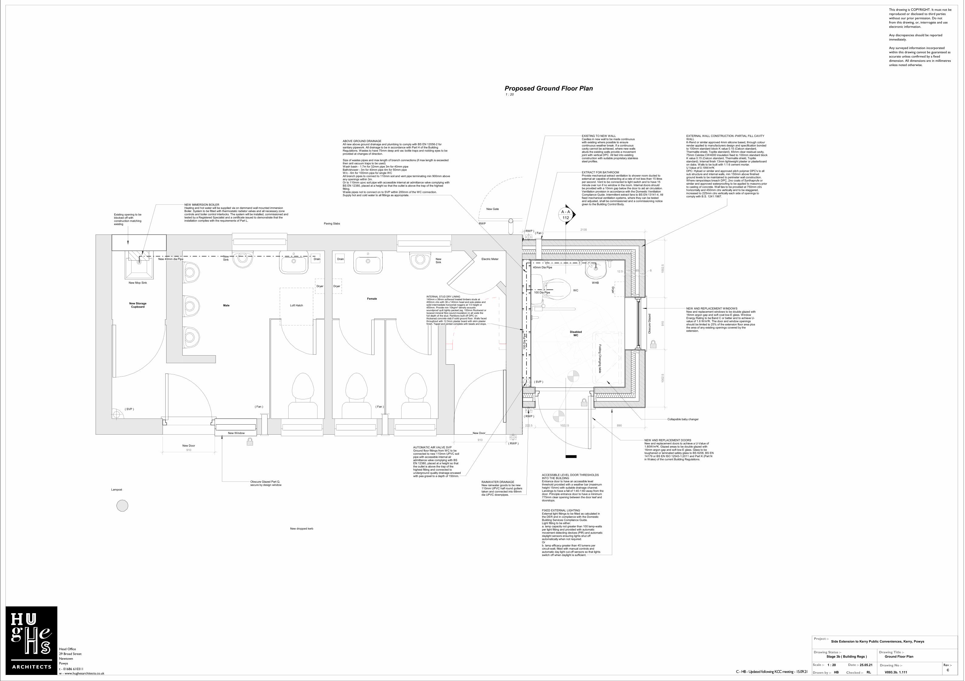
NEW AND REPLACEMENT WINDOWSNew and replacement windows to be double glazed with 16mm argon gap and soft coat low-E glass. Window Energy Rating to be Band C or better and to achieve U-value of 1.6 W/m²K. The door and window openings should be limited to 25% of the extension floor area plus the area of any existing openings covered by the extension.
EXTERNAL WALL CONSTRUCTION -PARTIAL FILL CAVITY WALLK-Rend or similar approved 4mm silicone based, through colour render applied to manufacturers design and specification bonded to 100mm standard block K value 0.15 (Celcon standard, Thermalite shield, Toplite standard). 65mm clear residual cavity, 75mm Celotex CW4000 insulation fixed to 100mm standard block K value 0.15 (Celcon standard, Thermalite shield, Toplite standard). Internal finish 13mm lightweight plaster or plasterboard on dabs. Walls to be built with 1:1:6 cement mortar.U Value of 0.19W/m²KDPC: Hyload or similar and approved pitch polymer DPC's to all sub structure and internal walls, min 150mm above finished ground levels to be maintained to perimeter wall construction. Where ramps/steps breach DPC, 2no coats of Synthaprufe or similar and approved waterproofing to be applied to masonry prior to casting of concrete. Wall ties to be provided at 750mm ctrs horizontally and 450mm ctrs vertically and to be staggered, increased to 225mm ctrs vertically each side of openings to comply with B.S. 1241:1987.
EXISTING TO NEW WALL Cavities in new wall to be made continuous with existing where possible to ensure continuous weather break. If a continuous cavity cannot be achieved, where new walls abuts the existing walls provide a movement joint with vertical DPC. All tied into existing construction with suitable proprietary stainless steel profiles.
EXTRACT FOR BATHROOMProvide mechanical extract ventilation to shower room ducted to external air capable of extracting at a rate of not less than 15 litres per second. Vent to be connected to light switch and to have 15 minute over run if no window in the room. Internal doors should be provided with a 10mm gap below the door to aid air circulation. Ventilation provision in accordance with the Domestic Ventilation Compliance Guide. Intermittent extract fans to BS EN 13141-4. All fixed mechanical ventilation systems, where they can be tested and adjusted, shall be commissioned and a commissioning notice given to the Building Control Body.
ABOVE GROUND DRAINAGEAll new above ground drainage and plumbing to comply with BS EN 12056-2 for sanitary pipework. All drainage to be in accordance with Part H of the Building Regulations. Wastes to have 75mm deep anti vac bottle traps and rodding eyes to be provided at changes of direction.
Size of wastes pipes and max length of branch connections (if max length is exceeded then anti vacuum traps to be used)Wash basin - 1.7m for 32mm pipe 3m for 40mm pipeBath/shower - 3m for 40mm pipe 4m for 50mm pipeW/c - 6m for 100mm pipe for single WCAll branch pipes to connect to 110mm soil and vent pipe terminating min 900mm above any openings within 3m. Or to 110mm upvc soil pipe with accessible internal air admittance valve complying with BS EN 12380, placed at a height so that the outlet is above the trap of the highest fitting.Waste pipes not to connect on to SVP within 200mm of the WC connection. Supply hot and cold water to all fittings as appropriate.
( Fan )
A - A
112
Drye
r
( SVP )
2135
1002.5
910
1002.5
222.5 1022.5 890
10
0 D
ia P
ipe
40mm Dia Pipe
100 Dia Pipe
( RWP )
( RWP )
INTERNAL STUD DRY LINING140mm x 38mm softwood treated timbers studs at 400mm ctrs with 38 x 140mm head and sole plates and solid intermediate horizontal noggins at 1/3 height or 450mm. Provide min 10kg/m³ density acoustic soundproof quilt tightly packed (eg. 100mm Rockwool or Isowool mineral fibre sound insulation) in all voids the full depth of the stud. Partitions built off DPC on thickened concrete slab if solid ground floor. Walls faced throughout with 12.5mm plaster board with skim plaster finish. Taped and jointed complete with beads and stops.
NEW AND REPLACEMENT DOORSNew and replacement doors to achieve a U-Value of 1.80W/m²K. Glazed areas to be double glazed with 16mm argon gap and soft low-E glass. Glass to be toughened or laminated safety glass to BS 6206, BS EN 14179 or BS EN ISO 12543-1:2011 and Part K (Part N in Wales) of the current Building Regulations.
RAINWATER DRAINAGENew rainwater goods to be new 110mm UPVC half round gutters taken and connected into 68mm dia UPVC downpipes.
AUTOMATIC AIR VALVE SVPGround floor fittings from WC to be connected to new 110mm UPVC soil pipe with accessible internal air admittance valve complying with BS EN 12380, placed at a height so that the outlet is above the trap of the highest fitting and connected to underground quality drainage encased with pea gravel to a depth of 150mm.
FIXED EXTERNAL LIGHTINGExternal light fittings to be fitted as calculated in the DER and in compliance with the Domestic Building Services Compliance Guide.Light fitting to be either:a. lamp capacity not greater than 100 lamp-watts per light fitting and provided with automatic movement detecting devices (PIR) and automatic daylight sensors ensuring lights shut off automatically when not required.Orb. lamp efficacy greater than 45 lumens per circuit-watt; fitted with manual controls and automatic day light cut-off sensors so that lights switch off when daylight is sufficient.
ACCESSIBLE LEVEL DOOR THRESHOLDS INTO THE BUILDINGEntrance door to have an accessible level threshold provided with a weather bar (maximum height 15mm) with suitable drainage channel. Landings to have a fall of 1:40-1:60 away from the door. Principle entrance door to have a minimum 775mm clear opening between the door leaf and doorstops.
NEW IMMERSION BOILERHeating and hot water will be supplied via on demmand wall mounted immersion Boiler. System to be fitted with thermostatic radiator valves and all necessary zone controls and boiler control interlocks. The system will be installed, commissioned and tested by a Registered Specialist and a certificate issued to demonstrate that the installation complies with the requirements of Part L.
910
910
New Door
( RWP )
Fo
ldin
g C
han
gin
g ta
ble
WC
WHB
12.5 10075
65100
8
New Mop Sink
New 40mm dia Pipe
Head Office
29 Broad Street
Newtown
Powys
t - 01686 610311
w - www.hughesarchitects.co.uk
Drawing No :-
Drawn by :-
Scale :- Date :-
Checked :-
Rev :-
Drawing Status :-
Project :-
Drawing Title :-
This drawing is COPYRIGHT. It must not be
reproduced or disclosed to third parties
without our prior permission. Do not
from this drawing, or, interrogate and use
electronic information.
Any discrepancies should be reported
immediately.
Any surveyed information incorporated
within this drawing cannot be guaranteed as
accurate unless confirmed by a fixed
dimension. All dimensions are in millimetres
unless noted otherwise.
1 : 20
C
Side Extension to Kerry Public Conveniences, Kerry, Powys
Ground Floor Plan
RLHB
25.05.21
Stage 3b ( Building Regs )
V093.3b. 1.111C - HB - Updated following KCC meeting - 15.09.21
1 : 20
Proposed Ground Floor Plan

Hardcore
Concrete
Insulation
Screed
LINTELS Provide proprietary lintels suitable for spans and loadings in compliance with Approved Document A and lintel manufactures standard tables. Stop ends, DPC trays and weep holes to be provided above all externally located lintels.
STRAPPING FOR PITCHED ROOFGable walls should be strapped to roofs at 2m centres. All external walls running parallel to roof rafters to be restrained at roof level using 1000mm x 30mm x 5mm galvanised mild steel horizontal straps or other approved to BSEN 845-1 built into walls at max 2000mm centres and to be taken across minimum 3 rafters and screw fixed. Provide solid noggins between rafters at strap positions. All wall plates to be 100 x 50mm fixed to inner skin of cavity wall using 30mm x 5mm x 1000mm galvanized metal straps or other approved to BSEN 845-1 at maximum 2m centres.
FLOOR CONSTRUCTION - SOLID FLOOR INSULATION OVER SLAB
Solid ground floor to consist of 200mm consolidated well-rammed hardcore. Blinded with 60mm sand blinding. Provide 125mm ST2 or Gen2 ground bearing slab concrete mix to conform to BS 8500-2 over a 1200 gauge polythene DPM. DPM to be lapped in with DPC in walls. Floor to be insulated over slab and DPM with 150mm thick Celotex FR5000. 25mm insulation to continue around floor perimeters to avoid thermal bridging. A VCL should be laid over the insulation boards and turned up 100mm at room perimeters behind the skirting, all joints to be lapped 150mm and sealed. Finish with 65mm sand/cement finishing screed with light mesh reinforcement. Where drain runs pass under new floor, provide A142 mesh 1.0m wide and min 50mm concrete cover over length of drain.Where existing suspended timber floor air bricks are covered by new extension, ensure cross-ventilation is maintained by connecting to 100mm dia UPVC pipes with 100mm concrete cover laid under the extension. Pipes to terminate at new 65mm x 215mm air bricks with cavity tray over.
U Value of 0.15W/m²K
260
125
150
65
DPCProvide horizontal strip polymer (hyload) damp proof course to both internal and external skins minimum 150mm above external ground level. New DPC to be made continuous with existing DPC’s and with floor DPM. Vertical DPC to be installed at all reveals where cavity is closed.
WALL TIESAll walls constructed using stainless steel vertical twist type retaining wall ties built in at 750mm ctrs horizontally, 450mm vertically and 225mm ctrs at reveals and corners in staggered rows. Wall ties to be suitable for cavity width and in accordance with BS EN 845-1.
CAVITIESProvide cavity trays over openings. All cavities to be closed at eaves and around openings using Thermabate or similar non combustible insulated cavity closers. Provide vertical DPCs around openings and abutments. All cavity trays must have 150mm upstands and suitable cavity weep holes (min 2) at max 900mm centres.
PITCHED ROOF INSULATION AT CEILING LEVELPitch 25° (imposed load max 0.75 kN/m² - dead load max 0.75 kN/m²)To achieve U value of 0.15 W/m²KTimber roof structures to be designed by an Engineer in accordance with NHBC Technical Requirement R5 Structural Design. Calculations to be based on BS EN 1995-1-1. Roofing tiles to match existing on 25 x 38mm tanalised sw treated battens on sarking felt supported on Roof trusses. trusses supported on 100 x 50mm sw wall plates. Insulation at ceiling level to be 100mm Rockwool insulation laid between ceiling joists with a further 200mm layer over joists (cross direction).Construct ceiling using sw joists at 400mm centres, finished internally with 12.5mm plasterboard and min 3mm thistle multi-finish plaster. Provide polythene vapour barrier between insulation and plasterboard. Provide opening at eaves level at least equal to continuous strip 25mm wide on two opposite sides to promote cross-ventilation. Restraint strapping - 100mm x 50mm wall plate strapped down to walls. Ceiling joists and rafters to be strapped to walls and gable walls, straps built into cavity, across at least 3 timbers with noggins. All straps to be 1000 x 30 x 5mm galvanized straps or other approved to BSEN 845-1 at 2m centres.
PITCHED ROOF VENTILATIONMaintain a 50mm air gap above insulation in the roof pitch to ventilate roof. Provide opening at eaves level at least equal to continuous strip 25mm wide and opening at ridge equal to continuous strip 5mm wide to promote ventilation.
225
2100
150
Ventilated ridge tile
Roof Trusses to truss manufacturers design and specification. Manufacturer to submit loading calculations to building control for approval.
EXTERNAL WALL CONSTRUCTION -PARTIAL FILL CAVITY WALLK-Rend or similar approved 4mm silicone based, through colour render applied to manufacturers design and specification bonded to 100mm standard block K value 0.15 (Celcon standard, Thermalite shield, Toplite standard). 50mm clear residual cavity, 60mm Kingspan Kooltherm K108 insulation fixed to 100mm standard block K value 0.15 (Celcon standard, Thermalite shield, Toplite standard). Internal finish 13mm lightweight plaster or plasterboard on dabs. Walls to be built with 1:1:6 cement mortar.U Value of 0.21W/m²KDPC: Hyload or similar and approved pitch polymer DPC's to all sub structure and internal walls, min 150mm above finished ground levels to be maintained to perimeter wall construction. Where ramps/steps breach DPC, 2no coats of Synthaprufe or similar and approved waterproofing to be applied to masonry prior to casting of concrete. Wall ties to be provided at 750mm ctrs horizontally and 450mm ctrs vertically and to be staggered, increased to 225mm ctrs vertically each side of openings to comply with B.S. 1241:1987.
BUILDING REGULATIONS NOTES
CDM REGULATIONS 2015The client must abide by the Construction Design and Management Regulations 2015. The client must appoint a contractor, if more than one contractor is to be involved, the client will need to appoint (in writing) a principal designer (to plan, manage and coordinate the planning and design work) and a principal contractor (to plan, manage and coordinate the construction and ensure there are arrangements in place for managing and organising the project).
THERMAL BRIDGINGCare shall be taken to limit the occurrence of thermal bridging in the insulation layers caused by gaps within the thermal element, (i.e. around windows and door openings). Reasonable provision shall also be made to ensure the extension is constructed to minimise unwanted air leakage through the new building fabric.
MATERIALS AND WORKMANSHIPAll works are to be carried out in a workmanlike manner. All materials and workmanship must comply with Regulation 7 of the Building Regulations, all relevant British Standards, European Standards, Agreement Certificates, Product Certification of Schemes (Kite Marks) etc. Products conforming to a European technical standard or harmonised European product should have a CE marking.
SITE PREPARATION Ground to be prepared for new works by removing all unsuitable material, vegetable matter and tree or shrub roots to a suitable depth to prevent future growth. Seal up, cap off, disconnect and remove existing redundant services as necessary. Reasonable precautions must also be taken to avoid danger to health and safety caused by contaminants and ground gases e.g. landfill gases, radon, vapours etc. on or in the ground covered, or to be covered by the building.
ELECTRICAL All electrical work required to meet the requirements of Part P (electrical safety) must be designed, installed, inspected and tested by a competent person registered under a competent person self certification scheme such as BRE certification Ltd, BSI, NICEIC Certification Services or Zurich Ltd. An appropriate BS7671 Electrical Installation Certificate is to be issued for the work by a person competent to do so. A copy of a certificate will be given to Building Control on completion.
BACKGROUND AND PURGE VENTILATIONBackground ventilation - Controllable background ventilation via trickle vents to in accordance with Approved Document F within the window frame to be provided to bathrooms at a rate of 2500mm² Purge ventilation - New Windows to have openable area in excess of 1/20th of their floor area, if the window opens more than 30° or 1/10th of their floor area if the window opens less than 30°Internal doors should be provided with a 10mm gap below the door to aid air circulation.Ventilation provision in accordance with the Domestic Ventilation Compliance Guide.
PART Q - SECURITYDoors and Windows Windows to be made to a design that has been shown by test to meet the security requirements of British Standards publication PAS 24:2016Frames to be mechanically fixed to the structure of the building in accordance with manufacturer's installation instructions.
Head Office
29 Broad Street
Newtown
Powys
t - 01686 610311
w - www.hughesarchitects.co.uk
Drawing No :-
Drawn by :-
Scale :- Date :-
Checked :-
Rev :-
Drawing Status :-
Project :-
Drawing Title :-
This drawing is COPYRIGHT. It must not be
reproduced or disclosed to third parties
without our prior permission. Do not
from this drawing, or, interrogate and use
electronic information.
Any discrepancies should be reported
immediately.
Any surveyed information incorporated
within this drawing cannot be guaranteed as
accurate unless confirmed by a fixed
dimension. All dimensions are in millimetres
unless noted otherwise.
1 : 20
C
Side Extension to Kerry Public Conveniences, Kerry, Powys
Section A - A
RLHB
25.05.21
Stage 3b ( Building Regs )
V093.3b. 1.112C - HB - Updated following KCC meeting - 15.09.21
1 : 20
Section A - A

New Door - colour TBC prior to ordering
New Window - UPVC white Obscure Glazing, Secure by Design
New External Wall -Render, Colour TBC prior to ordering.
Roof Finished with Tiles to match existing
New Door - Colour TBC prior to ordering.
A - A
112
UPVC rainwater goods to match existing
2100
New External Wall -Render, Colour TBC prior to ordering.
Proposed Roof to be finished with Tiles to match existing
Opening to be blocked up with brickwork to match existing
A - A
112
New External Wall -Render, Colour TBC prior to ordering.
New Window - UPVC white Obscure Glazing, Secure by Design
Timber Fascias - Painted black to match existing
UPVC Black Rainwater Goods
LEAD WORK AND FLASHINGSAll lead flashings, any valleys or soakers to be Code 5 lead and laid according to Lead Development Association. Flashings to be provided to all jambs and below window openings with welded upstands. Joints to be lapped min 150mm and lead to be dressed 200mm under tiles, etc. All work to be undertaken in accordance with the Lead Development Association recommendations.
900
1200
2100
FIXED EXTERNAL LIGHTINGExternal light fittings to be fitted as calculated in the DER and in compliance with the Domestic Building Services Compliance Guide.Light fitting to be either:a. lamp capacity not greater than 100 lamp-watts per light fitting and provided with automatic movement detecting devices (PIR) and automatic daylight sensors ensuring lights shut off automatically when not required.Orb. lamp efficacy greater than 45 lumens per circuit-watt; fitted with manual controls and automatic day light cut-off sensors so that lights switch off when daylight is sufficient.
1 number new 2F Schwegler, Bat Box
Head Office
29 Broad Street
Newtown
Powys
t - 01686 610311
w - www.hughesarchitects.co.uk
Drawing No :-
Drawn by :-
Scale :- Date :-
Checked :-
Rev :-
Drawing Status :-
Project :-
Drawing Title :-
This drawing is COPYRIGHT. It must not be
reproduced or disclosed to third parties
without our prior permission. Do not
from this drawing, or, interrogate and use
electronic information.
Any discrepancies should be reported
immediately.
Any surveyed information incorporated
within this drawing cannot be guaranteed as
accurate unless confirmed by a fixed
dimension. All dimensions are in millimetres
unless noted otherwise.
1 : 50
C
Side Extension to Kerry Public Conveniences, Kerry, Powys
Proposed Elevations
RLHB
25.05.21
Stage 3b ( Building Regs )
V093.3b. 1.113
1 : 50
Proposed Front Elevation
1 : 50
Proposed Rear Elevation
1 : 50
Proposed Side Elevation
1 : 50
Proposed Side Elevation 2
C - HB - Updated following KCC meeting - 15.09.21
![ÀÀij¦a¤ PROPOSED GROUND FLOOR LAYOUT PLAN · proposed ground floor layout plan ... ¡]¨Ó·½¡id¡ ¦a¤u¥± comparison of ground floor plans ²{¦³¦a¤uexisting ground](https://static.fdocuments.us/doc/165x107/5f59ced8559a814b617ecff6/a-proposed-ground-floor-layout-plan-proposed-ground-floor-layout-plan.jpg)