
GROUND PLANE CONTRIBUTION IN WIRELESS HANDHELD DEVICES USING RADAR CROSS
14
Progress In Electromagnetics Research M, Vol. 26, 101–114, 2012 GROUND PLANE CONTRIBUTION IN WIRELESS HANDHELD DEVICES USING RADAR CROSS SECTION ANALYSIS J. Anguera 1, 2, * and A. And´ ujar 1 1 Technology and Intellectual Property Rights Department, Frac- tus, Alcalde Barnils 64, Edificio Testa, Sant Cugat del Vall` es, Barcelona 08190, Spain 2 Electronics and Telecommunications Department, Universitat Ramon LLull, Barcelona, Spain Abstract—The ground plane of wireless handheld devices plays a significant role in the electromagnetic behavior determining bandwidth, efficiency, and radiation patterns. Therefore, it is necessary to determine the frequency region where the ground plane can be better excited, especially for low frequencies where the performance of the radiating system is critical due to size limitations with respect to the operating wavelength. A fast method based on the radar cross section (RCS) is presented for computing the frequency at which the ground plane is better excited. The proposal is applied to three typical wireless platforms: a handset phone, a smartphone, and a clamshell phone. The method is compared with characteristic mode analysis and the results demonstrate a very good agreement in the resonant frequency prediction. In addition, complex platforms using metallic strips and slots in the ground plane are analyzed using RCS which gives physical insight into the electromagnetic performance. 1. INTRODUCTION The ground plane plays a very important role in determining bandwidth, efficiency, and radiation patterns of wireless handheld devices. The significance of the ground plane needs to be better understood to optimize the radio electrical performance according to the specific form factor due to the apparition of more communication standards, especially in the low frequency region such as LTE700, and Received 17 August 2012, Accepted 11 September 2012, Scheduled 27 September 2012 * Corresponding author: Jaume Anguera ([email protected]).
Transcript of GROUND PLANE CONTRIBUTION IN WIRELESS HANDHELD DEVICES USING RADAR CROSS

Progress In Electromagnetics Research M, Vol. 26, 101–114, 2012
GROUND PLANE CONTRIBUTION IN WIRELESSHANDHELD DEVICES USING RADAR CROSS SECTIONANALYSIS
J. Anguera1, 2, * and A. Andujar1
1Technology and Intellectual Property Rights Department, Frac-tus, Alcalde Barnils 64, Edificio Testa, Sant Cugat del Valles,Barcelona 08190, Spain2Electronics and Telecommunications Department, Universitat RamonLLull, Barcelona, Spain
Abstract—The ground plane of wireless handheld devices playsa significant role in the electromagnetic behavior determiningbandwidth, efficiency, and radiation patterns. Therefore, it is necessaryto determine the frequency region where the ground plane can be betterexcited, especially for low frequencies where the performance of theradiating system is critical due to size limitations with respect to theoperating wavelength. A fast method based on the radar cross section(RCS) is presented for computing the frequency at which the groundplane is better excited. The proposal is applied to three typical wirelessplatforms: a handset phone, a smartphone, and a clamshell phone.The method is compared with characteristic mode analysis and theresults demonstrate a very good agreement in the resonant frequencyprediction. In addition, complex platforms using metallic strips andslots in the ground plane are analyzed using RCS which gives physicalinsight into the electromagnetic performance.
1. INTRODUCTION
The ground plane plays a very important role in determiningbandwidth, efficiency, and radiation patterns of wireless handhelddevices. The significance of the ground plane needs to be betterunderstood to optimize the radio electrical performance according tothe specific form factor due to the apparition of more communicationstandards, especially in the low frequency region such as LTE700, and
Received 17 August 2012, Accepted 11 September 2012, Scheduled 27 September 2012* Corresponding author: Jaume Anguera ([email protected]).

102 Anguera and Andujar
to the apparition of more platforms into the scene such as smartphonesand tablets.
It has been experimentally shown in [1] that for a PIFA antenna ona ground plane of 40 mm width, the optimum length to maximize thebandwidth is 0.4λ. In this regard, handset antennas operating in thefrequency region of 698–960 MHz where some standards are allocated(LTE700, GSM850/900), would require a ground plane length of144.7mm (computed at 829 MHz), which is too long for many devices.To solve this size limitation, some authors have proposed mechanismsto electrically enlarge the ground plane by using slots or metallicstrips to better excite its radiation mode, and as a consequence, largerbandwidth and efficiency are obtained [2–17].
Owing to the relevance of the ground plane, a fast method to givea physical insight into the ground plane electromagnetic performanceis proposed. The method employs the RCS parameter which is usedto compute the frequency at which maximum back-scattering occurs.To validate it, three platforms are used for the numerical experiments:a bar-type of 100mm × 40mm, a smartphone of 120mm × 50mm,and a clamshell (two connected plates of 80mm × 40mm). Theproposal is validated by comparing the results with those providedby characteristic mode analysis (Section 2). In Section 3, the methodis applied to understand the radiation of several handset platforms.Finally, conclusions are given in Section 4.
2. RCS ANALYSIS
The proposed method to compute the resonant frequency of thefundamental mode consists in illuminating the platform of the deviceby a plane wave impinging from the normal direction. In order to findout the fundamental mode, the polarization of the incoming wave is
x
zy
Metal plate
Ei = Ex
k
Hi
Incident plane wave
Figure 1. The metal plate is representative of a ground planeassociated to a bar-type wireless handheld device.

Progress In Electromagnetics Research M, Vol. 26, 2012 103
0.0
0.1
0.2
0.3
0.4
0.5
0.6
0.7
0.8
0.9
1.00.5
0
0.6
3
0.7
6
0.8
8
1.0
1
1.1
4
1.2
7
1.4
0
1.5
3
1.6
5
1.7
8
1.9
1
2.0
4
2.1
7
2.2
9
2.4
2
2.5
5
2.6
8
2.8
1
2.9
4
Mode 1 RCS
f0 max. RCS =1.246GHz
f0 max. MS =1.330GHz
Error=6.3%
0.0
0.1
0.2
0.3
0.4
0.5
0.6
0.7
0.8
0.9
1.0
0.5
0
0.6
3
0.7
6
0.8
8
1.0
1
1.1
4
1.2
7
1.4
0
1.5
3
1.6
5
1.7
8
1.9
1
2.0
4
2.1
7
2.2
9
2.4
2
2.5
5
2.6
8
2.8
1
2.9
4
Mode 1
RCS
f0 max. RCS =1.030GHz
f0 max. MS =1.080GHz
Error=4.6%
0.0
0.1
0.2
0.3
0.4
0.5
0.6
0.7
0.8
0.9
1.0
0.5
0
0.6
3
0.7
6
0.8
8
1.0
1
1.1
4
1.2
7
1.4
0
1.5
3
1.6
5
1.7
8
1.9
1
2.0
4
2.1
7
2.2
9
2.4
2
2.5
5
2.6
8
2.8
1
2.9
4
Mode 1
RC S
f0 max. RCS =0.640GHz
f0 max. MS =0.630GHz
Error=1.5%
(a) (b)
(c)
frequency [GHz]
Mod
al
Sig
nif
ican
ce. N
orm
ali
zed
RC
S
frequency [GHz]
Mod
al
Sig
nif
ican
ce. N
orm
ali
zed
RC
S
frequency [GHz]
Mod
al
Sig
nif
ican
ce. N
orm
ali
zed
RC
S
Figure 2. Comparison between normalized RCS and modal signifi-cance (MS); (a) bar-type platform 100mm × 40mm; (b) smartphoneplatform 120 mm×50 mm; (c) clamshell 80mm×40 mm for each upperand lower board.
aligned with the longest dimension of the device under test (Fig. 1).By using a commercial MoM code (IE3D), RCS is computed versus
frequency for the aforementioned devices. RCS is normalized in allcases to its maximum value, therefore RCS ranges from 1 to 0 wherethe maximum value 1 indicates the maximum backscattering whichcoincides with the better excitation of the metal plate, whereas 0 meanstransparency, i.e., no scattering is produced by the metal plate (Fig. 2).
In order to validate the method, the first characteristic mode(fundamental mode) has been computed for each platform. The modalsignificance (MS) parameter is used for comparison purposes. MSranges from 0 to 1 where 1 means that the mode can be excited inits maximum amplitude [18]. MS is computed using (1) from theeigenvalue λ obtained from the eigenvalue equation [18] using a MoMMatlab-based code [19].
MS =1
|1 + jλ| (1)
As suggested in [18], RCS can be computed as the summation of all

104 Anguera and Andujar
characteristic modes supported by a structure. In the present case, theproposed method directly calculates RCS to predict the fundamentalfrequency at which the ground plane can be excited, therefore only thefirst characteristic mode (λ1) is used.
Both RCS and MS have been compared for the three platformsconcluding that the prediction of the resonant frequency of thefundamental mode is in good agreement (error less than 6.3% worstcase — Fig. 2). It should be pointed out that both RCS and MSagree from the very low frequency region up to the resonance of thefundamental mode. Beyond that, as more modes are excited, RCS andMS diverge. The reason is that some higher modes cannot be excitedwhen the plane wave impinges to the metal plate from the normaldirection. Nevertheless, as far as the fundamental mode is concerned,the RCS is a simple and fast method to compute the resonant frequencyat which the ground plane of a wireless handheld device can be betterexcited.
Regarding the obtained results, it is observed how the resonanceof the fundamental mode decreases when the ground plane lengthis larger. For example, for the bar-type platform (Fig. 2(a)), theresonance based on the RCS method occurs at 1.246 GHz while it is1.030GHz for the smartphone platform (Fig. 2(b)). This means thatan antenna operating in the frequency region given by 698–960 MHzwould produce greater performance when integrated in the smartphoneplatform since the RCS indicates that the ground plane resonance isplaced at lower frequencies as will be demonstrated in the practicalcase of the following section. It is interesting to further note that100mm, the typical length of the ground plane of a bar-type platform,results in 0.41λ at 1.246GHz which is aligned with the experimentalresults to optimize the bandwidth of a PIFA antenna as demonstratedin [1]. In a similar manner, the 120 mm length of the ground planeof the smartphone platform results in 0.34λ at 1.030 GHz. This lesslength of the optimum length compared to the one obtained for the bar-type platform may be due to the wider dimension of the smartphoneplatform, 50 mm versus the 40 mm of the bar-type.
Owing to the clamshell phone in open position, the fundamentalmode is highly excited at frequencies around 0.63 GHz (Fig. 2(c)). Thisresult is aligned with aforementioned predictions, since it demonstratesagain that the larger the longitudinal dimension, the lower the resonantfrequency. This particular platform can be beneficial for integratingantennas operating in lower frequency ranges such as DVB-H (470–700MHz) antennas for TV reception [20]. For this case, the optimumelectrical length computed at 0.63 GHz is now 0.38λ (two times 80 mmplus the 20mm of the connecting strip).

Progress In Electromagnetics Research M, Vol. 26, 2012 105
For all cases, the current distribution associated to thefundamental mode presents the typical half-wave sinusoid behavior,maximum at the center of the metal plate and minimum at the shortedges. Such current distribution determines the radiation patternwhich presents an omni-directional behavior with a null in the directionof the longest side of the metal plate, i.e., similar to that produced bya half-wavelength dipole. This kind of radiation pattern is usuallyobtained for wireless handheld devices in the low frequency regionwhere the fundamental mode mainly contributes to radiation.
It is also interesting to note that for frequencies below thefrequency of the fundamental mode, the amplitude of both RCS andMS decreases which means that the excitation of the fundamental modebecomes more difficult. This fact, clearly limits the performance ofintegrated antennas in terms of bandwidth and efficiency below theresonance of the fundamental mode since both the antenna and theground plane are electrically small.
Finally, ground planes of wireless handheld devices are usuallyprinted on a thin substrate layer of a low-cost material (FR4, 1 mmthick and εr = 4.15). The effect of the dielectric coating can also betaken into account by the RCS analysis proposed here. For instance,for the bar-type, if the dielectric coating having the same size asthe ground plane is used, the frequency of the maximum RCS shiftsfrom 1.246GHz down to 1.140 GHz which represents a shift of 8%approximately.
3. APPLICATION
3.1. Ground Plane Size
To validate the usefulness of the RCS method, a non-resonant elementof only 5 mm × 5mm × 5mm is used to excite two ground planesrepresentative of a bar-type and a smartphone platform as describedin the previous section [21–23]. As explained before, the RCS presentslarger values in the low frequency region for the smartphone platformresulting at the end in a larger bandwidth of 26.3% (SWR ≤ 3) withrespect to the 17.7% for the bar-type platform (Fig. 3).
It is significant to emphasize that since the ground plane is aneffective means for radiation, the current antennas such as a PIFA canbe substituted by a ground plane booster as the one shown here whichat the end, in combination with a radiofrequency system, can performsimilar with a much less volume (Fig. 4).

106 Anguera and Andujar
0.808 GHz-6 dB
0.965 GHz-6 dB
0.961 GHz-6 dB
0.737 GHz-6 dB
DB ( |S(1,1)|)
Ground plane 100 mm x 40 mm
DB ( | S(2,2)|)
Ground plane 120 mm x 50 mm
Frequency (GHz)
Ref
lect
ion
coef
fici
ent
(dB
)
0.95 10.7 0.75 0.8 0.85 0.9 1.05 1.1
0
-2
-4
-6
-8
-10
-12
Figure 3. Measured reflection coefficient for a non-resonant elementof 5 mm× 5mm× 5mm regarding two different platforms.
Figure 4. Comparison of a PIFA and a ground plane booster both forGSM850-GSM900 operation. Size for the PIFA is 40 mm × 15mm ×6mm whereas the ground plane booster is only 5mm× 5mm× 5mm.
3.2. Enlarging the Ground Plane with Metallic Strips
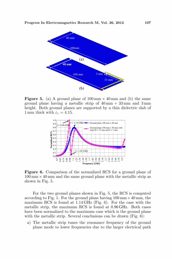
Another application of the proposed method is useful for analyzingcomplex platforms. In this sense, a ground plane of 100 mm lengthpresents less bandwidth than a ground plane having 120 mm lengthas shown before (Fig. 3). In some situations, the ground planecannot be enlarged due to mechanical requirements given by the phonemanufacturer. In those cases, if the bandwidth needs to be improved,some techniques adding intelligence in the ground plane can be usedsuch as for example adding slots in the ground plane [2–12] or addingmetallic strips [13–17]. As an example, the proposed method is usedhere to give a physical insight into the behavior of adding metallicstrips to a ground plane having 100 mm length (Fig. 5).
Progress In Electromagnetics Research M, Vol. 26, 2012 107
40 mm
100mm
100 mm
33 mm
3 mm
(a)
(b)
Figure 5. (a) A ground plane of 100mm × 40mm and (b) the sameground plane having a metallic strip of 40 mm + 33mm and 3mmheight. Both ground planes are supported by a thin dielectric slab of1mm thick with εr = 4.15.
0.0
0.1
0.2
0.3
0.4
0.5
0.6
0.7
0.8
0.9
1.0
0.5
0.6
2
0.7
4
0.8
6
0.9
8
1.1
1.2
2
1.3
4
1.4
6
1.5
8
1.7
1.8
2
1.9
4
2.0
6
2.1
8
2.3
2.4
2
2.5
4
2.6
6
2.7
8
2.9
f = 0.96 GHzf = 1.14 GHz
f = 1.02 GHz
Frequency [GHz]
No
rma
lize
d R
CS
strip 40 + 33 mm and h = 3 mmGround plane 100 mm x 40 mm with
Ground plane 100 mm x 40 mm
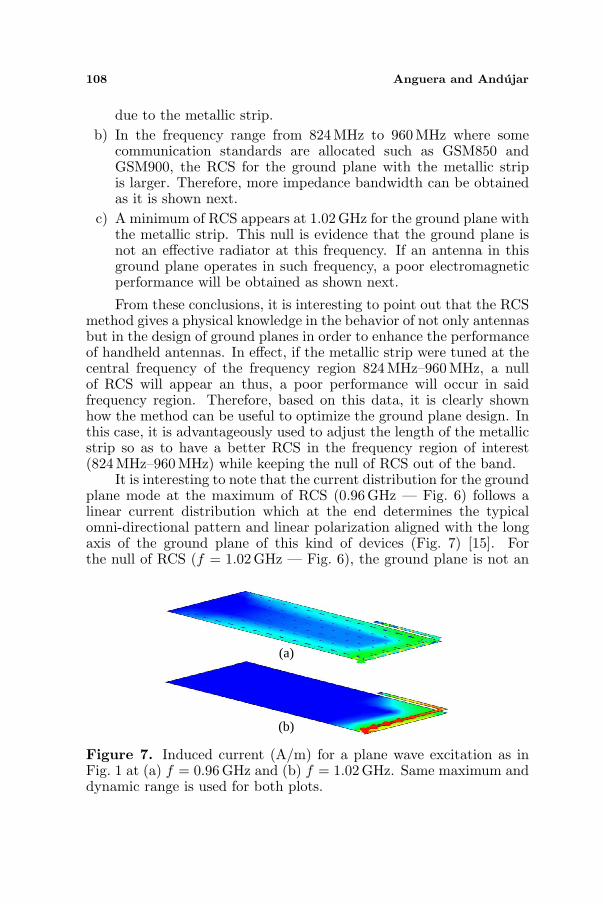
Figure 6. Comparison of the normalized RCS for a ground plane of100mm× 40mm and the same ground plane with the metallic strip asshown in Fig. 5.
For the two ground planes shown in Fig. 5, the RCS is computedaccording to Fig. 1. For the ground plane having 100mm×40mm, themaximum RCS is found at 1.14 GHz (Fig. 6). For the case with themetallic strip, the maximum RCS is found at 0.96 GHz. Both caseshave been normalized to the maximum case which is the ground planewith the metallic strip. Several conclusions can be drawn (Fig. 6):
a) The metallic strip tunes the resonance frequency of the groundplane mode to lower frequencies due to the larger electrical path
108 Anguera and Andujar
due to the metallic strip.b) In the frequency range from 824 MHz to 960 MHz where some
communication standards are allocated such as GSM850 andGSM900, the RCS for the ground plane with the metallic stripis larger. Therefore, more impedance bandwidth can be obtainedas it is shown next.
c) A minimum of RCS appears at 1.02 GHz for the ground plane withthe metallic strip. This null is evidence that the ground plane isnot an effective radiator at this frequency. If an antenna in thisground plane operates in such frequency, a poor electromagneticperformance will be obtained as shown next.
From these conclusions, it is interesting to point out that the RCSmethod gives a physical knowledge in the behavior of not only antennasbut in the design of ground planes in order to enhance the performanceof handheld antennas. In effect, if the metallic strip were tuned at thecentral frequency of the frequency region 824MHz–960 MHz, a nullof RCS will appear an thus, a poor performance will occur in saidfrequency region. Therefore, based on this data, it is clearly shownhow the method can be useful to optimize the ground plane design. Inthis case, it is advantageously used to adjust the length of the metallicstrip so as to have a better RCS in the frequency region of interest(824MHz–960MHz) while keeping the null of RCS out of the band.
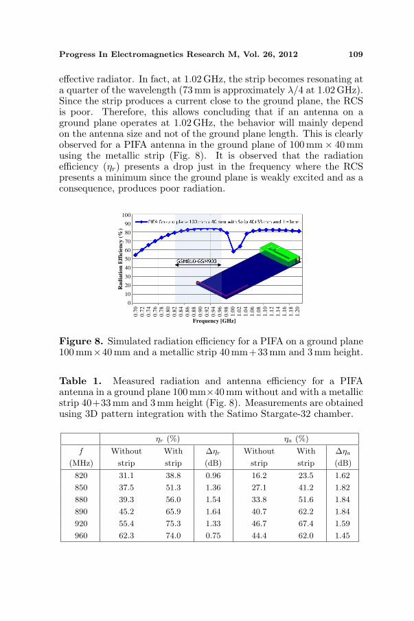
It is interesting to note that the current distribution for the groundplane mode at the maximum of RCS (0.96GHz — Fig. 6) follows alinear current distribution which at the end determines the typicalomni-directional pattern and linear polarization aligned with the longaxis of the ground plane of this kind of devices (Fig. 7) [15]. Forthe null of RCS (f = 1.02GHz — Fig. 6), the ground plane is not an
(a)
(b)
Figure 7. Induced current (A/m) for a plane wave excitation as inFig. 1 at (a) f = 0.96GHz and (b) f = 1.02GHz. Same maximum anddynamic range is used for both plots.
Progress In Electromagnetics Research M, Vol. 26, 2012 109
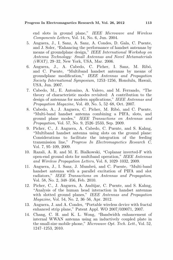
effective radiator. In fact, at 1.02GHz, the strip becomes resonating ata quarter of the wavelength (73 mm is approximately λ/4 at 1.02 GHz).Since the strip produces a current close to the ground plane, the RCSis poor. Therefore, this allows concluding that if an antenna on aground plane operates at 1.02 GHz, the behavior will mainly dependon the antenna size and not of the ground plane length. This is clearlyobserved for a PIFA antenna in the ground plane of 100 mm× 40mmusing the metallic strip (Fig. 8). It is observed that the radiationefficiency (ηr) presents a drop just in the frequency where the RCSpresents a minimum since the ground plane is weakly excited and as aconsequence, produces poor radiation.
0
10
20
30
40
50
60
70
80
90
100
0.7
0
0.7
2
0.7
4
0.7
6
0.7
8
0.8
0
0.8
2
0.8
4
0.8
6
0.8
8
0.9
0
0.9
2
0.9
4
0.9
6
0.9
8
1.0
0
1.0
2
1.0
4
1.0
6
1.0
8
1.1
0
1.1
2
1.1
4
1.1
6
1.1
8
1.2
0
Frequency [GHz]
Ra
dia
tion
Eff
icie
ncy
(%
)
Figure 8. Simulated radiation efficiency for a PIFA on a ground plane100mm×40 mm and a metallic strip 40 mm+33 mm and 3 mm height.
Table 1. Measured radiation and antenna efficiency for a PIFAantenna in a ground plane 100mm×40mm without and with a metallicstrip 40+33mm and 3mm height (Fig. 8). Measurements are obtainedusing 3D pattern integration with the Satimo Stargate-32 chamber.
ηr (%) ηa (%)
f
(MHz)
Without
strip
With
strip
∆ηr
(dB)
Without
strip
With
strip
∆ηa
(dB)
820 31.1 38.8 0.96 16.2 23.5 1.62
850 37.5 51.3 1.36 27.1 41.2 1.82
880 39.3 56.0 1.54 33.8 51.6 1.84
890 45.2 65.9 1.64 40.7 62.2 1.84
920 55.4 75.3 1.33 46.7 67.4 1.59
960 62.3 74.0 0.75 44.4 62.0 1.45

110 Anguera and Andujar
Thanks to the RCS analysis, the operation of the metallic strip toenhance the bandwidth in the 824MHz–960 MHz is better understood:the metallic strip is tuned so as to have the maximum of the RCS inthe frequency region of interest while avoiding the minimum of RCS tobe in said frequency region. By following this procedure, a PIFA on aground plane 100 mm×40mm having a bandwidth of 8.3% at 900 MHz(SWR ≤ 3) is improved up to 14.6% [15]. Moreover, since the RCSat the frequency region 824 MHz–960 MHz is larger when using themetallic strip (Fig. 8), not only the bandwidth improves but also theradiation efficiency. A larger RCS translates in a better excitationof the ground plane mode when an antenna operates in conjunctionwith the ground plane and therefore, larger radiation efficiency canbe obtained. Better matching and radiation efficiency translates intomore antenna efficiency (ηa = ηr · (1 − |S11|2)). As a brief summaryfrom [15], measured radiation and antenna efficiencies of the PIFAantenna of Fig. 8 with the effect of the metallic strip (Table 1) clearlyshows how the radiation efficiency increases around 1 dB across theGSM850-GSM900 frequency region. At the same time, due to a bettermatching, the antenna efficiency increases almost 2 dB.
It is interesting to point out that the use of metallic strip hasbeen proven not only to be useful for enhancing the bandwidth at thelow frequency region but also to provide a robust means for the handloading [24] and to control the near field for hearing-aid [25]. Therefore,the RCS method becomes an easy tool to give a physical insight whichcan lead to a better optimization of the metallic strip technique.
3.3. Enlarging the Ground Plane with Slots
Another technique employs slots in the ground plane for enhancing thebandwidth and radiation efficiency of handset antennas [2–12]. Thepresent RCS method is useful for this case to establish a comparisonbetween other methods to enlarge the ground plane as the one havinga metallic strip presented in the previous section (Fig. 9).
When properly designed, a slot in the ground plane forces thecurrent to travel a longer path. Therefore, the resonant frequencyof the fundamental mode of the ground plane can be shifted to thedesired frequency of operation, for instance, to 900 MHz, being thisfrequency the central frequency of the frequency region comprisingGSM850-GSM900 (Fig. 9). Based on the RCS analysis, it is shownhow a slot becomes advantageous to tune the resonant frequency ofthe ground plane mode to 900MHz. Moreover, this technique does notpresent a null as it is the case of the metallic strip. However, it may bemore challenging to be integrated into a wireless handheld device dueto the presence of other components such as a display or a battery.

Progress In Electromagnetics Research M, Vol. 26, 2012 111
0.0
0.1
0.2
0.3
0.4
0.5
0.6
0.7
0.8
0.9
1.0
0.5
0.6
2
0.7
4
0.8
6
0.9
8
1.1
1.2
2
1.3
4
1.4
6
1.5
8
1.7
1.8
2
1.9
4
2.0
6
2.1
8
2.3
2.4
2
2.5
4
2.6
6
2.7
8
2.9
Ground plane 100 mm x 40 mm
Frequency [GHz]
No
rma
lize
d R
CS
strip 40 + 33 mm and h = 3 mmGround plane 100 mm x 40 mm with
Ground plane 100 mm x 40 mm with slot
Figure 9. Comparison of RCS for three different ground planes:100mm × 40 mm, 100mm × 40mm with a metallic strip as shown inFig. 5, and a ground plane 100 mm× 40mm with slot 38 mm long and3mm width. The plane wave impinges the ground plane as shown inFig. 1. All ground planes are etched on a thin dielectric slab of 1mmthick and εr = 4.15.
It should be pointed out that the RCS bandwidth is larger for theslot case than the metallic strip (Fig. 9). Thus, one should expect toobtain more bandwidth using a slot in the ground plane rather than ametallic strip. In particular, the bandwidth using the metallic strip is14.6% for the PIFA in the 100 mm× 40mm ground plane [15] whereasthe same PIFA with a slot in the ground plane [5] has a bandwidthof 35.1% which clearly agrees with the RCS curves of Fig. 9. Froma quantitative point of view, it is interesting to link the impedancebandwidth and RCS bandwidth for the two ground planes. Usinga −3 dB RCS bandwidth (frequency at which the RCS drops 3 dB),the RCS−3 dB bandwidth for the ground plane with strip and withthe slot is 8.0% and 18.0%, respectively. This results in a ratio of2.25 which agrees with the impedance bandwidth ratio of 35.1% over14.6% resulting in 2.4. This makes the RCS method useful not only todetermine the frequency at which the best excitation of the groundplane mode occurs, but also to estimate the bandwidth of severalground plane configurations.
4. CONCLUSION
A fast method based on RCS for computing the resonance of thefundamental mode of a ground plane has been proposed. The methodsimplifies the computation of the frequency at which the ground planeof a wireless handheld device can be better excited. This method is

112 Anguera and Andujar
suitable for providing a first prediction on the benefits of the groundplane to increase the bandwidth and efficiency of wireless handhelddevices.
The proposed method has been also applied to give a physicalinsight in some enlarging ground plane techniques using metallic stripsand slots in the ground plane. In this sense, regarding the metallicstrip, when properly designed, the RCS shows a maximum in thefrequency region of interest and a minimum at a quarter of thewavelength of the strip. Therefore, this minimum must be placed out ofthe frequency region of interest. Finally, the RCS bandwidth is relatedto the impedance bandwidth. In this regard, the technique using aslot in the ground plane has been compared showing that the RCSbandwidth is larger. This ultimately results in a larger impedancebandwidth as it has been shown for a particular antenna placed inthe ground plane. The RCS method shows that the slot techniquepresented here not only presents more bandwidth for handset antennadesign but also it has not a minimum of RCS as it is the case of themetallic strip which limits the bandwidth of the solution.
This method helps to a better understanding of the behavior ofthe ground plane into the electromagnetic performance of wirelesshandheld devices.
ACKNOWLEDGMENT
The authors would like to thank the Spanish Ministry of Industry,Commerce, and Tourism for their support.
REFERENCES
1. Wu, T. Y. and K. L. Wong, “On the impedance bandwidth of aplanar inverted-F antenna for mobile handsets,” Microwave Opt.Tech. Lett., Vol. 32, 249–251, Feb. 20, 2002.
2. Vainikainen, P., J. Ollikainen, O. Kivekas, and I. Kelander,“Resonator-based analysis of the combination of mobile handsetantenna and chassis,” IEEE Transactions on Antennas andPropagation, Vol. 50, No. 10, 1433–1444, Oct. 2002.
3. Abedin, M. F. and M. Ali, “Modifying the ground plane and itseffect on planar inverted-F antennas (PIFAs) for mobile phonehandsets,” IEEE Antennas and Wireless Propagation Letters,Vol. 2, 2003.
4. Hossa, R., A. Byndas, and M. E. Bialkowski, “Improvement ofcompact terminal antenna performance by incorporating open-
Progress In Electromagnetics Research M, Vol. 26, 2012 113
end slots in ground plane,” IEEE Microwave and WirelessComponents Letters, Vol. 14, No. 6, Jun. 2004.
5. Anguera, J., I. Sanz, A. Sanz, A. Condes, D. Gala, C. Puente,and J. Soler, “Enhancing the performance of handset antennas bymeans of groundplane design,” IEEE International Workshop onAntenna Technology: Small Antennas and Novel Metamaterials(iWAT), 29–32, New York, USA, Mar. 2006.
6. Anguera, J., A. Cabedo, C. Picher, I. Sanz, M. Ribo,and C. Puente, “Multiband handset antennas by means ofgroundplane modification,” IEEE Antennas and PropagationSociety International Symposium, 1253–1256, Honolulu, Hawaii,USA, Jun. 2007.
7. Cabedo, M., E. Antonino, A. Valero, and M. Ferrando, “Thetheory of characteristic modes revisited: A contribution to thedesign of antennas for modern applications,” IEEE Antennas andPropagation Magazine, Vol. 49, No. 5, 52–68, Oct. 2007.
8. Cabedo, A., J. Anguera, C. Picher, M. Ribo, and C. Puente,“Multi-band handset antenna combining a PIFA, slots, andground plane modes,” IEEE Transactions on Antennas andPropagation, Vol. 57, No. 9, 2526–2533, Sep. 2009.
9. Picher, C., J. Anguera, A. Cabedo, C. Puente, and S. Kahng,“Multiband handset antenna using slots on the ground plane:Considerations to facilitate the integration of the feedingtransmission line,” Progress In Electromagnetics Research C,Vol. 7, 95–109, 2009.
10. Razali, A. R. and M. E. Bialkowski, “Coplanar inverted-F withopen-end ground slots for multiband operation,” IEEE Antennasand Wireless Propagation Letters, Vol. 8, 1029–1032, 2009.
11. Anguera, J., I. Sanz, J. Mumbru, and C. Puente, “Multi-bandhandset antenna with a parallel excitation of PIFA and slotradiators,” IEEE Transactions on Antennas and Propagation,Vol. 58, No. 2, 348–356, Feb. 2010.
12. Picher, C., J. Anguera, A. Andujar, C. Puente, and S. Kahng,“Analysis of the human head interaction in handset antennaswith slotted ground planes,” IEEE Antennas and PropagationMagazine, Vol. 54, No. 2, 36–56, Apr. 2012.
13. Anguera, J. and A. Condes, “Portable wireless device with fractalenhanced strip plane,” Patent Appl. WO 2007/039071, 2007.
14. Chang, C. H. and K. L. Wong, “Bandwidth enhancement ofinternal WWAN antenna using an inductively coupled plate inthe small-size mobile phone,” Microwave Opt. Tech. Lett., Vol. 52,1247–1253, 2010.

114 Anguera and Andujar
15. Anguera, J., A. Andujar, and C. Puente, “A mechanism toelectrically enlarge the ground plane of handset antennas: Abandwidth enhancement technique,” Microwave Opt. Tech. Lett.,Vol. 53, No. 7, 1512–1517, Jul. 2011.
16. Lindberg, P. and E. Ojefors, “A bandwidth enhancementtechnique for mobile handset antennas using wavetraps,” IEEETransactions on Antennas and Propagation, Vol. 54, No. 8,Aug. 2006.
17. Maoz, J. and M. Kadichevitz, “Apparatus and method forenhancing low-frequency operation of mobile communicationantennas,” US Patent 6, 940, 460, 2005.
18. Harrington, R. F. and J. R. Mautz, “Theory of characteristicmodes for conducting bodies,” IEEE Transactions on Antennasand Propagation, Vol. 19, No. 5, 622–628, Sep. 1971.
19. Makarov, S. N., Antenna and EM Modeling with Matlab, Wiley-Interscience, John Wiley & Sons, New York, Jul. 2002.
20. Jo, J.-H., B. Yu, K.-H. Kong, K. Jung, I.-Y. Lee, M.-J. Park,and B. Lee, “Multi-band internal antenna including DVB-Hband,” IEEE Antennas and Propagation Society InternationalSymposium, 972–975, Jun. 9–15, 2007.
21. Anguera, J., A. Andujar, C. Puente, and J. Mumbru,“Antennaless wireless device,” Patent Appl. WO2010/015365,Jul. 31, 2009.
22. Anguera, J., A. Andujar, C. Puente, and J. Mumbru,“Antennaless wireless device capable of operation in multiplefrequency regions,” Patent Appl. WO2010/015364, Jul. 31, 2009.
23. Andujar, A., J. Anguera, and C. Puente, “Ground plane boostersas a compact antenna technology for wireless handheld devices,”IEEE Transactions on Antennas and Propagation, Vol. 59, No. 5,1668–1677, May 2011.
24. Jung, J. M., S. J. Kim, K. H. Kong, J. S. Lee, and B. Lee,“Designing ground plane to reduce hand effects on mobilehandsets,” IEEE Antennas and Propagation Society InternationalSymposium, Honolulu, Hawaii, USA, Jun. 2007.
25. Holopainen, J., J. Ilvonen, O. Kivekas, R. Valkonen, C. Icheln,and P. Vainikainen, “Near-field control of handset antennas basedon inverted-top wavetraps: Focus on hearing-aid compatibility,”IEEE Antennas and Wireless Propagation Letters, Vol. 8, 592–595, 2009.