Ground Improvement for Khulna Soft Clay Soil · 2020-01-13 · Ground Improvement for Khulna Soft...
229
Ground Improvement for Khulna Soft Clay Soil Final Report Mott MacDonald AsCAP Project Reference Number. BAN2083A October 2017
Transcript of Ground Improvement for Khulna Soft Clay Soil · 2020-01-13 · Ground Improvement for Khulna Soft...

Ground Improvement for KhulnaSoft Clay SoilFinal Report
Mott MacDonald
AsCAP Project Reference Number. BAN2083A
October 2017

Ground Improvement for Khulna Soft Clay Soil
Page 2
The views in this document are those of the authors and they do not necessarily reflect theviews of the Research for Community Access Partnership (ReCAP), Mott MacDonald or CardnoEmerging Markets (UK) Ltd for whom the document was prepared.
Quality assurance and review tableVersion Author(s) Reviewer(s) Date
1 Ian DuncanLewis PhillipsAbdullah Al BakyShamsul IslamRichard Lebon
Maysam AbedinDr Jasper Cook
20 December 2017
2 Ian DuncanLewis PhillipsCarlos Santos
Maysam AbedinDr Jasper Cook
08 February 2018
Ground Improvement for Khulna Soft Clay Soil
Page 3
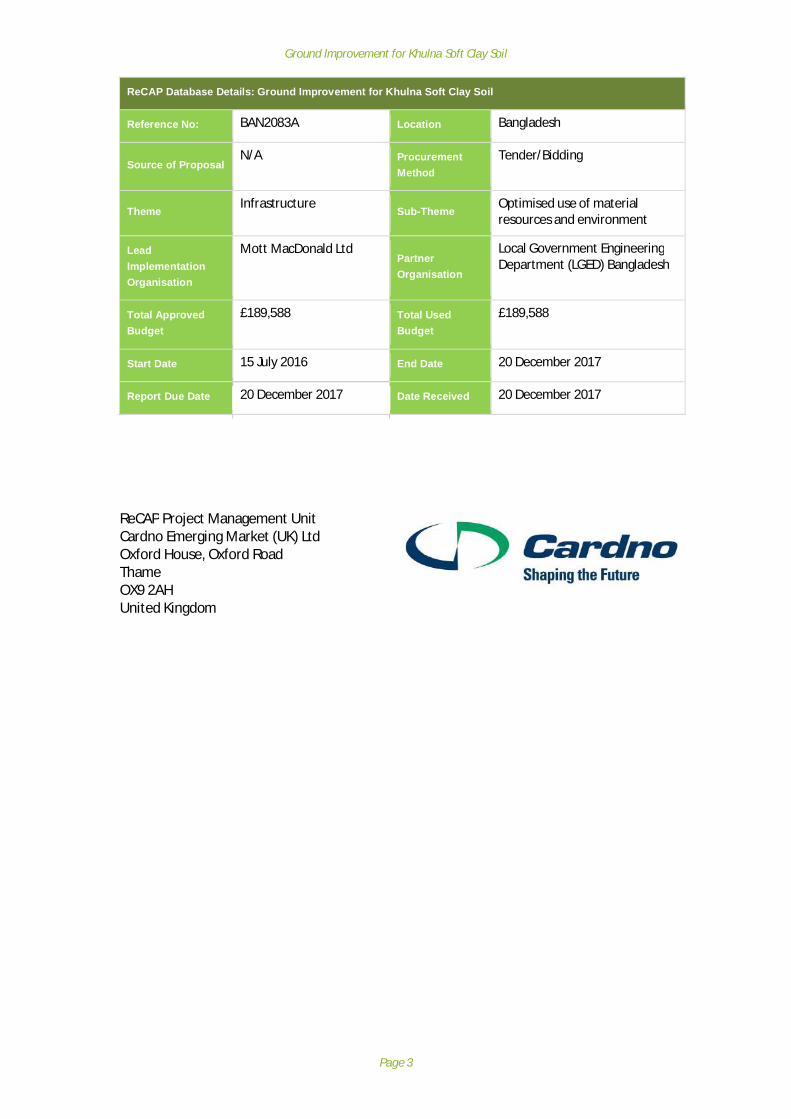
ReCAP Database Details: Ground Improvement for Khulna Soft Clay Soil
Reference No: BAN2083A Location Bangladesh
Source of ProposalN/A Procurement
MethodTender/Bidding
Theme Infrastructure Sub-Theme Optimised use of materialresources and environment
LeadImplementationOrganisation
Mott MacDonald LtdPartnerOrganisation
Local Government EngineeringDepartment (LGED) Bangladesh
Total ApprovedBudget
£189,588 Total UsedBudget
£189,588
Start Date 15 July 2016 End Date 20 December 2017
Report Due Date 20 December 2017 Date Received 20 December 2017
ReCAP Project Management UnitCardno Emerging Market (UK) LtdOxford House, Oxford RoadThameOX9 2AHUnited Kingdom

Ground Improvement for Khulna Soft Clay Soil
Page 4
AbstractThere are major concerns for the resilience of rural road embankments exposed to anaggressive coastal environment, in areas of high flood risk and where embankments areoften constructed on soft soil deposits with high compressible organic content. This studycollates the relevant findings from existing research, field observations and groundinvestigation to understand the effectiveness and limitations of existing groundimprovement techniques implemented in Khulna region, and to develop appropriaterecommendations to overcome the typical construction challenges for road embankmentsand structures in Khulna region. Using the results gained observational ground models havebeen developed for to help better understand the deformation mechanisms and assess thelikely contributory causes. Ground improvement techniques are presented that areconsidered either (a) technically feasible and (b) within the likely budget for rural roadconstruction together with guidance for implementation to deal with specific constructionissues. Topics for further research are presented that will improve the ability to applyground improvement techniques in Khulna Region.
Key wordsBangladesh, Khulna, Rural roads, Soft Clays, Organic Soil, Earthworks, Settlement,embankment failure, Ground Improvement, Infrastructure research, Transport servicesresearch
ASIA COMMUNITY ACCESS PARTNERSHIP (AsCAP)Safe and sustainable transport for rural communities
AsCAP is a research programme, funded by UK Aid, with the aim of promotingsafe and sustainable transport for rural communities in Asia. The AsCAP
partnership supports knowledge sharing between participating countries inorder to enhance the uptake of low cost, proven solutions for rural access
that maximise the use of local resources. AsCAP is brought together with theAfrica Community Access Partnership (AfCAP) under the Research for
Community Access Partnership (ReCAP), managed by Cardno EmergingMarkets (UK) Ltd.
See www.research4cap.org

Ground Improvement for Khulna Soft Clay Soil
Page 5
AcknowledgementsThe project team would like to greatly acknowledge the continuous support provided byLGED engineers throughout the tenure of the project.
Acronyms, Units and Currencies$ United States Dollar (US$ 1.00 ≈ provide conversion to local currencies)ADB Asian Development BankAFCAP Africa Community Access PartnershipASCAP Asia Community Access PartnershipAASHTO American Association of State Highway and Transportation OfficialsASTM American Society for Testing MaterialsCBR California Bearing RatioCC Cement columnISG Improved subgrade layerKUET Khulna University of Engineering & TechnologyLGED Local Government Engineering DepartmentLL Liquid LimitLTP Load transfer platformPI Plasticity IndexPJVD Prefabricated Jute vertical drainPL Plastic LimitPVD Prefabricated vertical drainSCP Sand compaction pileSD Sand drainSPT Standard Penetration TestUSCS Unified Soil Classification System
Glossary of termsApproach embankment A bank constructed from earth materials raised above the
surrounding land to raise the highway alignment level with, forexample, a river crossing, such as a bridge.
Bearing capacity Relates to the strength of the soil and ability to sustain an appliedload before failure (ultimate limit state) or unsatisfactorydeformation (serviceability limit state). Can be expressed as eitherultimate bearing capacity (unfactored) or allowable bearingpressure (factored to reduce deformation)
CAPEX / OPEX CAPEX: Capital expenditure related to non-routine remediation orrenewal of an asset, for example an earthwork or culvert.OPEX: Operational expenditure related to routine maintenanceactivities, e.g. unblocking drainage, or vegetation management.
Consolidation The process of volume reduction (through reduction in voidswithin a soil mass) due to the application of load to a soil mass, forexample the construction of an embankment. Consolidationincreases strength and stiffness of the soil.
Deep foundation Foundations for structures that are formed by driving or drilling areinforcement member through a weaker ground to bear on morecompetent material at depth. Load is supported through eitherend bearing or shaft resistance.

Ground Improvement for Khulna Soft Clay Soil
Page 6
Deformation Relates to the degree of movement experienced as a result ofloading. Related to the soil stiffness, compressibility, andconsolidation.
Effective shear strength The magnitude of the shear stress that a soil can sustain duringlong term loading under effective stress conditions (fully drained)
Embankment A constructed bank constructed from earth materials raised abovethe surrounding land to prevent flooding or improve verticalalignment.
Foundation soil The natural soil layer on which an embankment or foundation isconstructed
Geotextile A woven or punched membrane used to provide tensile resistancewithin, for example, a pavement or earthwork
Ground model An illustration of the materials, properties, behaviours, andmechanisms operating at a site. Commonly used to depict theapplication of construction activities and the consequences arising/ pertinent issues for design.
Improved sub-grade Where the sub-grade strength is lower than required, andimproved sub-grade layer can be used, comprising higher qualitymaterial and in some cases a geotextile layer.
Load transfer platform Load transfer platforms are used under embankments orstructures for spreading vertical loads into an underlyingfoundation comprising discrete inclusions, such as piles or cementcolumns.
Plasticity & Atterberg Limits Laboratory determine soil indicators, that relate to compositionsand mineralogy. Often used in correlations to derive geotechnicalparameters.
Pore-water pressure Refers to the pressure of water held within voids in a soil mass.The pressure varies with depth below the phreatic surface and alsoresponds to external loading conditions, depending on the rate ofloading and permeability of the soil. For example, the undrainedshear strength develops under short term loading conditions, andin a clay soil, the pore water pressures cannot dissipate – henceundrained behaviour that is governed by the presence of water inthe soil. As long as stability of the soil is not affected (ability towithstand the applied load), the pore water pressures dissipate asconsolidation occurs, and the soil mass strength is improved as thesoil particles become more tightly packed. The pore waterpressure is subtracted from the total stress level, to give effectivestress.
Reflective cracking Surface cracking in a pavement that is reflective of underlyingbehaviour.
Settlement – total / differential Movement of the ground surface resulting from consolidation.Shallow foundation Foundations for structures that are constructed near surface in
open excavations, generally comprising reinforced concrete stripsor slabs.
Stability Relates to the strength of the soil and ability to sustain an appliedload. See also bearing capacity.
Sub-grade The prepared earth surface on which the road pavement isconstructed
Undrained shear strength The magnitude of the shear stress that a soil can sustain duringshort term loading

Ground Improvement for Khulna Soft Clay Soil
Page 7
Contents
Abstract ...................................................................................................................................... 4Key words ................................................................................................................................... 4Acknowledgements .................................................................................................................... 5Acronyms, Units and Currencies ................................................................................................. 5Glossary of terms........................................................................................................................ 5Executive Summary .................................................................................................................. 11Background and Research Objectives ....................................................................................... 11Data gathering and ground models .......................................................................................... 11Ground Improvement Techniques for Soft Soil in Khulna Region ............................................. 11Guidelines/Recommendations for Ground Improvement in Khulna Soft Clay Soils.................. 12Further research work .............................................................................................................. 121 Background ....................................................................................................................... 13
1.1 Background to Project 131.2 Failure mechanisms for soft soil and impacts 131.3 Research Objectives 141.4 Methodology 14
2 Sources of information ..................................................................................................... 162.1 Literature Review 162.2 LGED Design Guidance and Procedural Documents 162.3 Stakeholder meetings 162.4 Field Investigations 162.5 Existing Field Investigations 162.6 Stakeholder Workshop – summary report 16
3 Regional Geology and Ground Conditions ........................................................................ 173.1 Introduction 173.2 Regional Geology 173.3 Ground Conditions of Khulna Region 183.4 Existing Borehole logs 193.5 Review of geotechnical properties in the Khulna Area 193.6 Summary of Geology 22
4 Review of Condition of Earthworks and Structures built on soft ground in Khulna Region234.1 Purpose of Field Review 234.2 Site Selection Criteria 234.3 Initial Site visits 244.4 Observational Sites 254.5 Discussion related to common observations 274.6 Intrusive Investigation Sites 28
5 Field and Laboratory Testing ............................................................................................. 315.1 Field Testing Results 315.2 Interpretation of Probe Test Results 325.3 Laboratory Testing Results 335.4 Summary of laboratory testing undertaken 335.5 Derivation of Geotechnical Parameters 365.6 Review of site specific parameters vs regional data from literature review 38
6 Development of Ground Models ...................................................................................... 406.1 General 406.2 Review of key findings / indicators 406.3 Analytical Ground Model 416.4 Factors not related to soft foundation soil 48
7 Life-cycle considerations for constructing rural roads on soft foundation soils ................ 507.1 Asset life-cycle 50

Ground Improvement for Khulna Soft Clay Soil
Page 8
7.2 Planning and Procurement 517.3 Design Phase 527.4 Construction Phase 547.5 Operate, Maintain and Renew Phase 54
8 Current Guidance for Design & Construction of Rural Roads ............................................ 558.1 General 55
9 Ground Improvement Techniques for Soft Soil in Khulna Region ..................................... 599.1 Overview 599.2 Sand Compaction Pile (SCP) 599.3 Sand Drain with surcharge loading 619.4 Prefabricated Vertical Drain (and Jute Drain) with surcharge loading 639.5 Cement Columns 649.6 Geotextile / geogrid basal reinforcement 669.7 Excavate and Replace / Displacement 689.8 Ground Improvement methods – settlement and bearing capacity 709.9 Typical Costs / complexity 71
10 Guidelines/Recommendations for Ground Improvement in Khulna Soft Clay Soils .......... 7310.1 General 7310.2 Remedial Applications 7310.3 New build and widening applications 81
11 Further research work ...................................................................................................... 9011.1 General 9011.2 Further research themes 9011.3 Recommended Further Research Topics (short list) 9211.4 Future stage(s) of the project 93
12 Conclusions ....................................................................................................................... 94References ................................................................................................................................ 96Appendix A: Stakeholder meetings .......................................................................................... 99Appendix B: Stakeholder workshop questions and responses ................................................ 100Appendix C: Review of GI and lab testing in Bangladesh ........................................................ 115Appendix D:Existing Borehole Data ........................................................................................ 117Appendix E: Site Location plans, observations and test data .................................................. 118Appendix F: Ground Models ................................................................................................... 171Appendix G: Compendium of photographs ............................................................................ 185Appendix H: Example Geotechnical Risk Register ................................................................... 190Appendix I: International Ground Improvement Techniques ................................................. 193Appendix J: Ground Improvement Techniques for Rural Roads in Bangladesh ...................... 196Appendix K:Ground Investigation Techniques for Rural Roads in Bangladesh ........................ 197
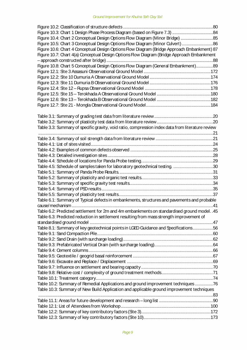
Figure 1.1: Potential outcomes from building on soft ground ..................................................... 14Figure 5.1: A-Line Plasticity Chart ............................................................................................... 36Figure 6.1: Undrained shear strength with depth determined from SPT N and theoreticalnormally consolidated approach (Fat Clay) ................................................................................. 44Figure 6.2: Undrained shear strength with depth determined from SPT N and theoreticalnormally consolidated approach (Lean Clay) .............................................................................. 45Figure 6.3: Improvement in undrained strength resulting from embankment construction on FatClay foundation soil .................................................................................................................... 47Figure 7.1: Stages within the asset lifecycle ................................................................................ 50Figure 7.2: Factors that influence the potential for damage to structures and earthworks throughthe asset lifecycle ....................................................................................................................... 50Figure 7.3: Design Phase – Management of Risks associated with Soft Ground ........................... 52Figure 10.1: Classification of embankment defects ..................................................................... 79
Ground Improvement for Khulna Soft Clay Soil
Page 9
Figure 10.2: Classification of structure defects ........................................................................... 80Figure 10.3: Chart 1 Design Phase Process Diagram (based on Figure 7.3) .................................. 84Figure 10.4: Chart 2 Conceptual Design Options Flow Diagram (Minor Bridge) ........................... 85Figure 10.5: Chart 3 Conceptual Design Options Flow Diagram (Minor Culvert) .......................... 86Figure 10.6: Chart 4 Conceptual Design Options Flow Diagram (Bridge Approach Embankment) 87Figure 10.7: Chart 4(a) Conceptual Design Options Flow Diagram (Bridge Approach Embankment– approach constructed after bridge) ......................................................................................... 88Figure 10.8: Chart 5 Conceptual Design Options Flow Diagram (General Embankment) .............. 89Figure 12.1: Site 3 Assasuni Observational Ground Model ........................................................ 172Figure 12.2: Site 10 Dumuria A Observational Ground Model ................................................... 174Figure 12.3: Site 11 Dumuria B Observational Ground Model ................................................... 176Figure 12.4: Site 12 – Rupsa Observational Ground Model ....................................................... 178Figure 12.5: Site 15 – Terokhada A Observational Ground Model ............................................. 180Figure 12.6: Site 13 – Terokhada B Observational Ground Model ............................................. 182Figure 12.7: Site 21 - Mongla Observational Ground Model ...................................................... 184
Table 3.1: Summary of grading test data from literature review ................................................. 20Table 3.2: Summary of plasticity test data from literature review ............................................... 20Table 3.3: Summary of specific gravity, void ratio, compression index data from literature review .................................................................................................................................................. 21Table 3.4: Summary of soil strength data from literature review ................................................ 21Table 4.1: List of sites visited ...................................................................................................... 24Table 4.2: Examples of common defects observed ..................................................................... 25Table 4.3: Detailed investigation sites ........................................................................................ 28Table 4.4: Schedule of locations for Panda Probe testing. ........................................................... 29Table 4.5: Schedule of samples taken for laboratory geotechnical testing. ................................. 30Table 5.1: Summary of Panda Probe Results. .............................................................................. 31Table 5.2: Summary of plasticity and organic test results ............................................................ 33Table 5.3: Summary of specific gravity test results...................................................................... 34Table 5.4: Summary of PSD results ............................................................................................. 35Table 5.5: Summary of plasticity test results ............................................................................... 37Table 6.1: Summary of Typical defects in embankments, structures and pavements and probablecause/mechanism ...................................................................................................................... 41Table 6.2: Predicted settlement for 2m and 4m embankments on standardised ground model. . 45Table 6.3: Predicted reduction in settlement resulting from mass strength improvement ofstandardised ground model ....................................................................................................... 47Table 8.1: Summary of key geotechnical points in LGED Guidance and Specifications ................. 56Table 9.1: Sand Compaction Pile................................................................................................. 60Table 9.2: Sand Drain (with surcharge loading) ........................................................................... 62Table 9.3: Prefabricated Vertical Drain (with surcharge loading) ................................................. 64Table 9.4: Cement columns ........................................................................................................ 66Table 9.5: Geotextile / geogrid basal reinforcement ................................................................... 67Table 9.6: Excavate and Replace / Displacement ........................................................................ 69Table 9.7: Influence on settlement and bearing capacity ............................................................ 70Table 9.8: Relative cost / complexity of ground treatment methods ........................................... 71Table 10.1: Treatment category.................................................................................................. 74Table 10.2: Summary of Remedial Applications and ground improvement techniques ............... 76Table 10.3: Summary of New Build Application and applicable ground improvement techniques .................................................................................................................................................. 83Table 11.1: Areas for future development and research – long list ............................................. 90Table 12.1: List of Attendees from Workshop ........................................................................... 100Table 12.2: Summary of key contributory factors (Site 3).......................................................... 172Table 12.3: Summary of key contributory factors (Site 10) ........................................................ 173

Ground Improvement for Khulna Soft Clay Soil
Page 10
Table 12.4: Summary of key contributory factors (Site 11) ........................................................ 175Table 12.5: Summary of key contributory factors (Site 12) ........................................................ 177Table 12.6: Summary of key contributory factors (Site 15) ........................................................ 179Table 12.7: Summary of key contributory factors (Site 13) ........................................................ 181Table 12.8: Summary of key contributory factors (Site 21) ........................................................ 184Table 12.9: Hazard Impact Table.......................................................................................... 190Table 12.10: Hazard Likelihood Index .................................................................................... 190Table 12.11: Risk Level Matrix ............................................................................................... 191Table 12.12: Designers Actions .............................................................................................. 191Table 12.13: Geotechnical Risk Register ................................................................................ 192Table 12.14: Ground improvement techniques for rural roads in Bangladesh ........................ 196Table 12.15: Typical investigation and sampling regime for minor bridge .............................. 197Table 12.16: Typical investigation and sampling regime for minor culvert ............................. 197Table 12.17: Typical investigation and sampling regime for approach embankments ............ 198Table 12.18: Typical investigation and sampling regime for general embankments................ 198

Ground Improvement for Khulna Soft Clay Soil
Page 11
Executive SummaryThis Final Report presents the findings of the Ground Improvement for Khulna Soft Clay Soilresearch project. The Final Report is the concluding task of seven key milestones in the deliveryof the project.
Background and Research ObjectivesThere are major concerns for the resilience of rural road embankments exposed to an aggressivecoastal environment, in areas of high flood risk and where embankments are often constructedon soft soil deposits, sometimes with high compressible organic content. This study collates therelevant findings from existing research, field observations and ground investigation tounderstand the effectiveness and limitations of existing ground improvement techniquesimplemented in Khulna region, and to develop appropriate recommendations to overcome thetypical construction challenges for road embankments and structures in Khulna region.
Data gathering and ground modelsThe sources of information used to develop the findings of the Final Report are wide and varied.The principal sources comprise; stakeholder meetings, national/international publications &academic research, site visits and intrusive investigations.
A review of 21No. sites was undertaken to present an overview of the existing field situation.Seven sites were identified for further detailed investigation. Field work at the test sites took theform of in-situ testing using a Panda 2 Probe and shallow hand excavated pits, from whichsamples were retrieved for geotechnical classification testing. Using the results gained from theabove literature review, field surveys and laboratory testing stages, observational ground modelshave been developed for the 7No. sites to help better understand the deformation mechanismsand assess the likely contributory causes.
The probable cause/mechanisms leading to the defects that are attributable to soft ground aredeformation resulting from settlement and stability issues resulting from low bearing capacity orlack of lateral support. Based on the geometrical and geotechnical data collated, simplifiedanalytical models have been used to assess deformation and stability that contribute to theobserved defects. Typically expected magnitudes of deformation have been presented,depending on loading.
Ground Improvement Techniques for Soft Soil in Khulna RegionGround improvement techniques are presented that are considered either (a) technicallyfeasible and (b) within the likely budget for rural road construction. From the literature review,and discussions with local stakeholders, the techniques are mostly in use in Bangladesh,although not necessarily for the rural road application. The ground improvement techniquesconsidered here are: -
· Sand Compaction Pile· Sand Drain (with surcharge)· Prefabricated Vertical Drains (with surcharge)· Geotextile basal reinforcement· Cement Columns· Excavate and replace / displacement
The impact of the various techniques with respect to ground deformation and stability ispresented together with a review of the practicality of implementing each technique and therelative cost.

Ground Improvement for Khulna Soft Clay Soil
Page 12
Guidelines/Recommendations for Ground Improvement in Khulna Soft Clay SoilsFor repair to existing assets, the treatments have been sub-divided into Maintenance,Remediation and Renewal, with definitions of what each category means in terms of expectedlife and cost. The limitations of some ground improvement methods for remedial applicationsare also highlighted.
For new build, the design scenarios have been identified and key design attributes matched tosolutions with increasing cost and likely effectiveness.
A series of design decision flowcharts have been presented to aid the practitioner in selectingthe appropriate ground treatment solution to match the engineering requirement. These aresummarised as follows: -
· Chart 1 Design Phase Process Diagram· Chart 2 Conceptual Design Options Flow Diagram (Minor Bridge)· Chart 3 Conceptual Design Options Flow Diagram (Minor Culvert)· Chart 4 Conceptual Design Options Flow Diagram (Bridge Approach Embankment)· Chart 4a Conceptual Design Options Flow Diagram (Bridge Approach Embankment –
approach constructed after bridge)· Chart 5 Conceptual Design Options Flow Diagram (General Embankment)
To accompany the design flowcharts, typical quantities for ground investigations for eachengineering application has been presented as an informative Appendix.
Further research workBased on the research, appropriate ground improvement techniques to address typical defectsand new build scenarios are presented. Some of the techniques are widely used in Bangladesh,but others are not.
A long list of further research topics is presented and recommended topics given that areconsidered to offer most benefit to the development of suitable ground treatment of soft soils inKhulna Region. The methods where further research is recommended are: -
· Field Trials with sand compaction pile / sand drains to demonstrate plant and skills· Effectiveness of Basal Reinforcement in limiting settlement and avoiding BC failure· Shallow soil mixing with admixtures to improve shear strength of foundation soil· Shallow soil mixing with fibres to improve shear strength of foundation soil· Spatial mapping and statistical evaluation of data
The next phase of the project may include the following stages: -
· Design Guidelines: Production of design guidelines & training for ground improvementtechniques for rural road construction on soft foundation soils including typical designs,standard details and specifications for standard engineering applications
· Construction Guidelines: Development of field guidelines for construction practitionersincluding capacity building / training of field engineers and construction practitioners forapplication of the new construction guidelines.

Ground Improvement for Khulna Soft Clay Soil
Page 13
1 Background
1.1 Background to Project
There are major concerns for the resilience of rural road embankments exposed to an aggressivecoastal environment, in areas of high flood risk and where embankments are often constructedon soft soil deposits with high compressible organic content. It is noted that the severity of theproblem, where road embankments and structures can experience settlement failures relativelyearly in their lifespan; and the scale of the problem, with over 4500km of village roads, 800km ofupazila roads, and 475km of union roads – combine to produce a significant problem that needsto be overcome.
There is a large body of existing research including geological and hydrological studies that arespecific to the Khulna region, and further international studies, research projects and innovativeengineering projects that have addressed the issues of durability, settlement and seismicbehaviour for infrastructure founded on soft and compressible soils.
This study intends to collate the relevant findings from this existing research, to understand theeffectiveness and limitations of existing ground improvement techniques implemented in Khulnaregion, and to develop appropriate recommendations to overcome the typical constructionchallenges for road embankments and structures in Khulna region.
1.2 Failure mechanisms for soft soil and impacts
Whilst the specific failure mechanisms operating on structures and highways embankments inKhulna region are discussed in later Chapters, common failure mechanisms include:
· Settlement of earthworks;· Failure of earthworks;· Differential movement between earthworks and structures;· Differential movement of bridge abutments and piers;· Culverts structures settling as a result of earthworks construction;· Creep settlement of organic materials.
Figure 1.1 below demonstrates that the potential impacts listed above, can lead directly to acycle of economic loss. Investment in the design, methods of construction and maintenance ofrural road assets provides significant improvement in transport links, trade and economicdevelopment and this is recognised by the Government of the People’s Republic of Bangladesh.

Ground Improvement for Khulna Soft Clay Soil
Page 14
Figure 1.1: Potential outcomes from building on soft ground
1.3 Research Objectives
The specific objective of this project identified in the Terms of Reference is ‘to establish a cost-effective ground improvement technique(s) which will be applicable in Khulna and other similarregions which have soft soils’ and this is to be supported by improvements to understanding inthe following particular technical research area:
· The characteristics of the soil in the Khulna Region;· The existing level of knowledge related to these soils;· Identification of the current status of the structures in the Khulna Region and identify
factors that are causing deterioration;· Any geographical difference and possible reasons behind such differences;· Recommendations of the remedial measures to existing structures and guidelines for
ground improvements for the construction of new rural roads in the study region.
The final deliverable is a ‘Final Report outlining the recommendations on appropriate remedialmeasures and ground improvement techniques based on the literature review, analysis ofexisting situation and testing of the soils’. Field and laboratory based research or trials oftechniques are outside the scope of the project at this stage.
1.4 Methodology
The Project Methodology involves the completion of the following key tasks accompanied by atechnical deliverable:
1. Inception Report and Literature Review;2. Field Situation Analysis, including some diagnostic field tests;3. Field and laboratory testing;4. Laboratory Test Report;5. Draft Report;6. Stakeholder Workshop;7. Final Report.

Ground Improvement for Khulna Soft Clay Soil
Page 15
The Final report presents the findings from all previous phases of the research project. The Finalreport incorporates stakeholder feedback on the Draft Report and presentations held at theworkshop.

Ground Improvement for Khulna Soft Clay Soil
Page 16
2 Sources of information
2.1 Literature Review
A comprehensive literature review was undertaken as part of the project. The full list ofpublications reviewed is included in the References at the end of the report.
2.2 LGED Design Guidance and Procedural Documents
LGED have provided copies of current guidance and procedural documents that have beendeveloped for use on rural road projects. The list of documents reviewed are noted inChapter 8.
2.3 Stakeholder meetings
Numerous stakeholder meetings have taken place during the course of the project todirectly gain information and request additional material. The records of the significantmeetings are provided in Appendix A.
2.4 Field Investigations
Numerous sites, the locations of which were agreed with LGED, were visited to gain thebackground information on the current situation and defects typical of rural roads in Khulna.A total of 21No. sites were visited and relevant data recorded.
For seven selected sites, ground investigation was undertaken to gain information regardingthe foundation soil and embankment fill materials. Soils were subject to in situ testing andlaboratory testing,
2.5 Existing Field Investigations
Geotechnical data relating to soil stratification and properties were supplemented byexisting ground investigation data and parameters determined from the literature review.
2.6 Stakeholder Workshop – summary report
Direct feedback on the research material gathered and recommendations presented at theStakeholder Workshop held in September 2017. The record of the workshop is included inAppendix B.

Ground Improvement for Khulna Soft Clay Soil
Page 17
3 Regional Geology and Ground Conditions
3.1 Introduction
The regional geology of Bangladesh and ground conditions in the Khulna Region has beenwidely described and a summary from the literature review is provided.
Also included is reference to existing borehole logs provided by Prosoil Consultants.
An overall summary of the expected ground conditions in the Khulna Region is given and thisis used further in later Chapters of this report.
3.2 Regional Geology
Mollah (2003) explains in his paper entitled “Geotechnical conditions of the deltaic alluvialplains of Bangladesh and associated problems”, that: the Himalayan Range, has had a greatinfluence on the evolution of the river systems in Bangladesh and on the development of isextensive river delta, which has a sedimentation history ranging from the Pleistocene toRecent. Mollah explains that from development projects, there is soil test data available foralmost the entire Bangladesh deltaic plain and that this information indicates that thesubsoil of the deltaic alluvial plains generally consists of sandy material though heemphasises that it may vary significantly over short lateral distances as a result of frequentand erratic occurrences of compressible organic silt and peat mixtures.
The author explains and confirms the known issue that the foundation competency of theupper 6-10 m of ground in the deltaic alluvial plains of Bangladesh has been assessed as ‘lowto very low’. The characteristics of the soils indicate susceptibility to erosion, piping,liquefaction phenomenon, etc. Furthermore, he adds that the variable nature of thedeposits makes the prediction of local soil conditions very difficult. Mollah explains that auniformly textured fine sand with a ‘moderate to high’ bearing capacity typically exists in thesoil profile, particularly below 20 m depth, but this is obviously a deep layer that would needto be utilized for its engineering properties via piled foundations (he notes that thismoderately to high bearing capacity sand stratum is totally absent in swampy areas).
Mollah elaborates on potential construction problems and subdivides them intogeotechnical and environmental issues. The former includes foundation problems inbuildings, bridges, and hydraulic structures etc., attributed to the weak and erratic nature ofthe surficial soil (and points out that geotechnical problems are often compounded by thephysiographical and geomorphological environment of the country). Flood and river bankerosion are identified as the main environmental problems, considered by the author asposing ‘an enormous threat to life, property and construction’. Recommendations toovercome these problems are made.
Arifuzzaman and Hasan (2013) report how, over the past 50 years, Dhaka, the Capital ofBangladesh, has experienced a rapid growth of urban population. They explain how this highpopulation increase has necessitated a rapid expansion of the city. Arifuzzaman and Hasanexplain that those areas of Dhaka that have subsoil that can be considered competent forbuilding construction are already exhausted and that as such, new areas are being reclaimedby both government and private agencies using dredged fill from nearby river sources. It isreported that in most cases, the practice for developing such areas is just to fill lowlands (1.5m to 5.5 m) by dredged soils collected from nearby riverbank and riverbed sources. It isfound that the dredged soil is typically silty sand and that the mean grain size and fines

Ground Improvement for Khulna Soft Clay Soil
Page 18
content of such material typically varies from 0.148 mm to 0.200 mm and from 17.4 to27.6%, respectively.
Arifuzzaman and Hasan explain that a very soft organic layer exists below the reclamationfilling layer that is highly plastic and highly compressible. This very soft organic layer isdetermined to exist because filling soil is directly placed on the marshy low land and uponthe vegetation and other organic materials. After a time, these organic materials beneaththe filling soil decompose and produce the problem soft organic layer. The authors foundthat the thickness of the soft layer varies in the range from 0.5m to 8.5m. Moisture contentof organic layer was determined to vary from 32 to 84% whilst liquid limit and plasticityindex vary from 42 to 193% and from 14 to 68%, respectively. It is seen that this organic soil(OL to OH) is very soft in nature and shows high moisture content and highly plasticbehaviour. Organic content of the soft soil varies from 4.7 to 28.7%. Unconfinedcompressive strength and failure strain vary from 6 to 66 kPa and from 7 to 15%,respectively. In addition, initial void ratio, compression index and coefficient of consolidationvary from 0.88 to 3.90, from 0.26 to 1.10 and from 0.22 to 16.85 m2/yr, respectively. Theauthors summarise this soil as being highly compressible with very low shear strength. SPT Nvalues of the organic layer are only 1 to 2. The filling layer was determined to possess SPT Nvalues of 2 to 11.
The authors observed that settlement of the organic layer varied from approximately 240mm to 640 mm between times period of 1.8 to 12.7 years, respectively, due to a calculatedoverburden pressure of 100 kPa. Moreover, the authors felt that the existing organic layermay cause negative skin friction and ensuing difficulties for piled foundations. It ismentioned that further studies are being conducted to develop or design desired suitableground improvement techniques or alternative foundation systems for such sub-soilconditions.
3.3 Ground Conditions of Khulna Region
Of the materials sourced for the literature review, perhaps the key papers on the geology ofthe Khulna Region have emerged as “Engineering Geology of Khulna Metropolitan City Area”by Reshad et al (2004) and “Urban Geology: A Case of Khulna City Corporation, Bangladesh”by Adhikari et al (2006). These papers both reflect on metropolitan areas, but where theexperience remains relevant to the ground conditions encountered in the rural roadscenario.
Reshad et al (2004) explain that the presence of thick soft deposits is the major constraintfor the development of the city. The ground of Khulna city is described as comprising‘compressible and collapsible sediments’ consisting of very soft silt and organic clay-silt.These deposits are explained to be very moist, saline and where non-organic of low plasticityexhibiting low shear strength characteristics and a propensity for liquefaction. The paperattempts to divide the area into characteristic soil complexes and of those developed, the‘Western Complex’ is described as having the worst subsurface conditions with upper softsoils up to 20m thick (correlating with the findings of Mollah (2003).
Adhikari et al (2006) again discuss how the city of Khulna lies on the Late Holocene - Recentalluvium of the Ganges deltaic plain in the north and Ganges estuarine plain in the south.They described how lithologically, the area is composed of coarse to very fine sand, silt, siltyclay and clay in various proportions up to a depth of 300m, explaining how the stratigraphyunderlying the city shows ‘seven cycles of sedimentation having age connotation from UpperMiocene to Recent age’.
Ground Improvement for Khulna Soft Clay Soil
Page 19
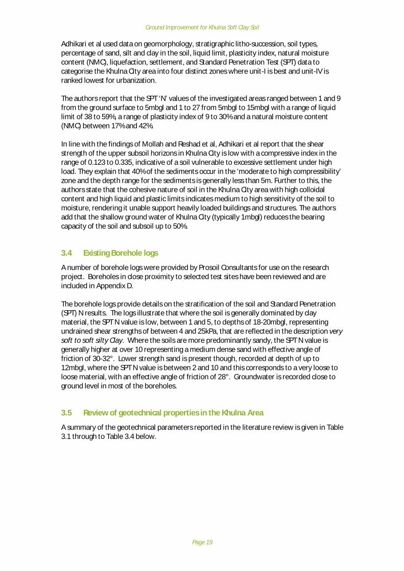
Adhikari et al used data on geomorphology, stratigraphic litho-succession, soil types,percentage of sand, silt and clay in the soil, liquid limit, plasticity index, natural moisturecontent (NMC), liquefaction, settlement, and Standard Penetration Test (SPT) data tocategorise the Khulna City area into four distinct zones where unit-I is best and unit-IV isranked lowest for urbanization.
The authors report that the SPT ‘N’ values of the investigated areas ranged between 1 and 9from the ground surface to 5mbgl and 1 to 27 from 5mbgl to 15mbgl with a range of liquidlimit of 38 to 59%, a range of plasticity index of 9 to 30% and a natural moisture content(NMC) between 17% and 42%.
In line with the findings of Mollah and Reshad et al, Adhikari et al report that the shearstrength of the upper subsoil horizons in Khulna City is low with a compressive index in therange of 0.123 to 0.335, indicative of a soil vulnerable to excessive settlement under highload. They explain that 40% of the sediments occur in the ‘moderate to high compressibility’zone and the depth range for the sediments is generally less than 5m. Further to this, theauthors state that the cohesive nature of soil in the Khulna City area with high colloidalcontent and high liquid and plastic limits indicates medium to high sensitivity of the soil tomoisture, rendering it unable support heavily loaded buildings and structures. The authorsadd that the shallow ground water of Khulna City (typically 1mbgl) reduces the bearingcapacity of the soil and subsoil up to 50%.
3.4 Existing Borehole logs
A number of borehole logs were provided by Prosoil Consultants for use on the researchproject. Boreholes in close proximity to selected test sites have been reviewed and areincluded in Appendix D.
The borehole logs provide details on the stratification of the soil and Standard Penetration(SPT) N results. The logs illustrate that where the soil is generally dominated by claymaterial, the SPT N value is low, between 1 and 5, to depths of 18-20mbgl, representingundrained shear strengths of between 4 and 25kPa, that are reflected in the description verysoft to soft silty Clay. Where the soils are more predominantly sandy, the SPT N value isgenerally higher at over 10 representing a medium dense sand with effective angle offriction of 30-32°. Lower strength sand is present though, recorded at depth of up to12mbgl, where the SPT N value is between 2 and 10 and this corresponds to a very loose toloose material, with an effective angle of friction of 28°. Groundwater is recorded close toground level in most of the boreholes.
3.5 Review of geotechnical properties in the Khulna Area
A summary of the geotechnical parameters reported in the literature review is given in Table3.1 through to Table 3.4 below.

Ground Improvement for Khulna Soft Clay Soil
Page 20
Table 3.1: Summary of grading test data from literature review
Literature review reference:1 – Reshad et al (2004). Engineering Geology of Khulna Metropolitan City Area2 – Rafizul et al (2012). The effect of chemical admixtures on the geotechnical parameters of organic soil: a newstatistical model
Table 3.2: Summary of plasticity test data from literature reviewSoil samples fromupper 3m depth
Min Max Plasticity classification
Moisture content (mc) % 332 471 Generally, CL, CI, MH,CHLiquid Limit (LL) % 332 621
Plastic Limit (PL) % 281 371
Plasticity Index (PI) % 221 311
Soil samples from 3mto 6m depth
Min Max Plasticity classification
Moisture content (mc) % 213 582 Generally, CL, CI, MH,CH
Liquid Limit (LL) % 273 863
Plastic Limit (PL) % 183 763
Plasticity Index (PI) % NR NR No Results available
Soil samples 0m to20m depth
Min Max Plasticity classification
Moisture content (mc) % 114 884 Generally, CL, CH, ML,MH. Also OH, OL.Liquid Limit (LL) % 244 955
Plastic Limit (PL) % 26 805
Plasticity Index (PI) % 96 905
Literature review reference:1 – Reshad et all (2004). Engineering Geology of Khulna Metropolitan City Area2 – Alamgir and Chowdhury (2004). Ground improvement methods recently practiced to solve the Geotechnicalengineering problems in Bangladesh3 – Rabee and Rafizul (2012). Strength and compressibility characteristics of reconstituted organic soil at Khulna regionof Bangladesh4 – Serajuddin, M (1998). Some geotechnical studies on Bangladesh soils: A summary of papers between 1957-965 – Rafizul et al (2012). The effect of chemical admixtures on the geotechnical parameters of organic soil: a newstatistical model6 – Adhikari et al (2006). Urban geology: a case study of Khulna City Corporation, Bangladesh
Results with no depth stated have been included in 0-20mbgl range
Soil samples Min Max USCS Classification
Clay fraction (%) 61 281 Single result of MH,others not definedSilt fraction (%) 541 881
Sand fraction (%) 3.51 381
Organic content (%) 322 712 Not defined

Ground Improvement for Khulna Soft Clay Soil
Page 21
Table 3.3: Summary of specific gravity, void ratio, compression index data from literature reviewSoil samples up to 3mdepth
Min Max Notes
Specific Gravity 2.52 2.753
Initial void ratio, e NR NR No Results available
Compression index, Cc NR NR No Results available
Soil samples 3m to 6mdepth
Min Max
Specific Gravity 24 2.7310 Low result indicative oforganic content
Initial void ratio, e NR NR No Results available
Compression index, Cc 0.2573 0.3913
Soil samples 0m to 20mdepth
Min Max
Specific Gravity 1.126 2.883 Low result indicative oforganic content
Initial void ratio, e 0.7065 7.9621 High result indicative oforganic content
Compression index, Cc 0.085 2.1793 Large range due to soiltypes included
Literature review reference:1 – Sarkar et al (2005). Interpretation of Rice Husk Ash on Geotech Properties of Cohesive Soil2 – Reshad et al (2004). Engineering Geology of Khulna Metropolitan City Area3 - Alamgir and Chowdhury (2004). Ground improvement methods recently practiced to solve the Geotechnicalengineering problems in Bangladesh4 - Rabee and Rafizul (2012). Strength and compressibility characteristics of reconstituted organic soil at Khulna regionof Bangladesh5 - Serajuddin, M (1998). Some geotechnical studies on Bangladesh soils: A summary of papers between 1957-966 - Rafizul et al (2012). The effect of chemical admixtures on the geotechnical parameters of organic soil: a newstatistical model
Results with no depth stated have been included in 0-20mbgl range
Table 3.4: Summary of soil strength data from literature reviewSoil samples up to 3mdepth
Min Max Notes
SPT ‘N’ value 21 101 12-47 obtained for siltysand layers6
Undrained shear strength,cu (kPa)
- -
Soil samples 3m to 6mdepth
Min Max
SPT ‘N’ value 22 42
Undrained shear strength,cu (kPa)
122 262 Method of derivation notstated
Soil samples 0m to 16mdepth
Min Max
SPT ‘N’ value 11 291
Undrained shear strength,cu (kPa)
122 442 Method of derivation notstated
Ground Improvement for Khulna Soft Clay Soil
Page 22
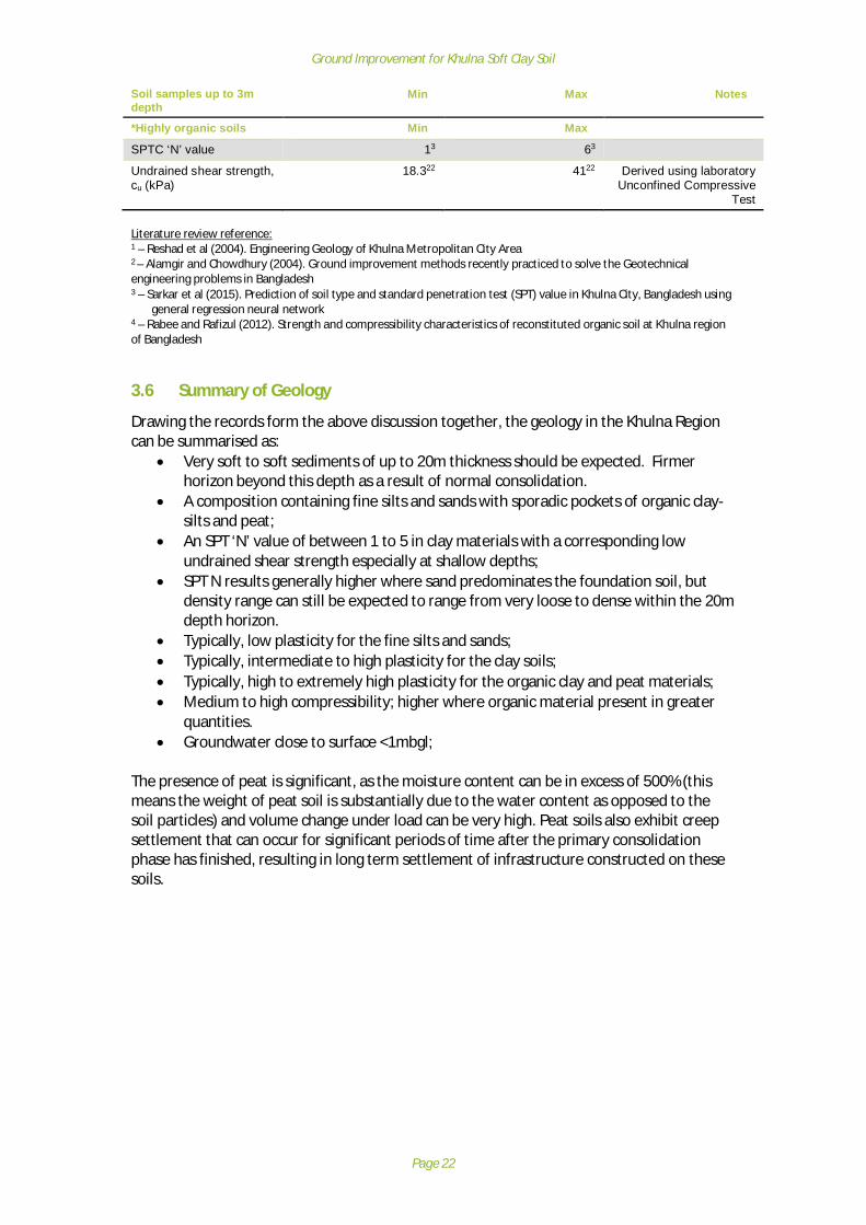
Soil samples up to 3mdepth
Min Max Notes
*Highly organic soils Min Max
SPTC ‘N’ value 13 63
Undrained shear strength,cu (kPa)
18.322 4122 Derived using laboratoryUnconfined Compressive
Test
Literature review reference:1 – Reshad et al (2004). Engineering Geology of Khulna Metropolitan City Area2 – Alamgir and Chowdhury (2004). Ground improvement methods recently practiced to solve the Geotechnicalengineering problems in Bangladesh3 – Sarkar et al (2015). Prediction of soil type and standard penetration test (SPT) value in Khulna City, Bangladesh using
general regression neural network4 – Rabee and Rafizul (2012). Strength and compressibility characteristics of reconstituted organic soil at Khulna regionof Bangladesh
3.6 Summary of Geology
Drawing the records form the above discussion together, the geology in the Khulna Regioncan be summarised as:
· Very soft to soft sediments of up to 20m thickness should be expected. Firmerhorizon beyond this depth as a result of normal consolidation.
· A composition containing fine silts and sands with sporadic pockets of organic clay-silts and peat;
· An SPT ‘N’ value of between 1 to 5 in clay materials with a corresponding lowundrained shear strength especially at shallow depths;
· SPT N results generally higher where sand predominates the foundation soil, butdensity range can still be expected to range from very loose to dense within the 20mdepth horizon.
· Typically, low plasticity for the fine silts and sands;· Typically, intermediate to high plasticity for the clay soils;· Typically, high to extremely high plasticity for the organic clay and peat materials;· Medium to high compressibility; higher where organic material present in greater
quantities.· Groundwater close to surface <1mbgl;
The presence of peat is significant, as the moisture content can be in excess of 500% (thismeans the weight of peat soil is substantially due to the water content as opposed to thesoil particles) and volume change under load can be very high. Peat soils also exhibit creepsettlement that can occur for significant periods of time after the primary consolidationphase has finished, resulting in long term settlement of infrastructure constructed on thesesoils.

Ground Improvement for Khulna Soft Clay Soil
Page 23
4 Review of Condition of Earthworks and Structures built on softground in Khulna Region
4.1 Purpose of Field Review
The overall purpose of the review was: -
· To identify typical sites where remedial works are required· To identify the reasons why the defects occurred
A broad review of a wide range of sites was undertaken to present an overview of theexisting field situation with the purpose of selecting a limited number of appropriate sitesfor more detailed investigation during Task 3 (Field and Laboratory Testing). Informationrelating to the sites was recorded using pro-forma to record common data including:
· Earthwork characteristics; length, height, slope angle, adjacent land;· Sources of water; hydrology, drainage;· Construction details; drainage, pavement, highway layout;· Highway structures; bridges, culverts, walls;· Observed condition; settlement, differential settlement, structural distress, drainage
issues;
4.2 Site Selection Criteria
In partnership with LGED, Mott MacDonald developed the below list of classification criteriafor the rural road study sites, that fall within three broad classes:
A. Road / Site characterisation.B. Ground improvement techniques used?C. Interaction with structures?
The classification criteria are as follows:
A. ROAD / SITE CHARACTERISATION:
1. What is the classification of the road?(E.g. upazila)
2. Proximity to a watercourse?(If yes, how close by is the watercourse?)
3. What is the elevation of the road?4. Is the road at risk from flooding?
(If yes, what are the specifics of this flood risk?)5. Is the pavement coarse bound or unbound?
(What materials have been used and in what layer thicknesses?)6. Are there soft ground conditions?
(If yes, is the depth of this soft layer(s) known?)7. Are there instances of organic soils within this soft layer(s)?
(If yes, what are the horizontal and vertical extents of this material?)
B. GROUND IMPROVEMENT TECHNIQUES USED?
8. Was the existing road constructed using any ground improvement techniques?(If yes, are design drawings available?)

Ground Improvement for Khulna Soft Clay Soil
Page 24
9. Is the road on embankment or at grade?(If on embankment, how high and what are the rough slope angles?)
10. Has the existing road / embankment failed or is it showing signs of distress?(What are the signs of distress? what is the apparent mode(s) of failure? – if theroad hasn’t failed, why is this?)
11. Have remedial works been undertaken?(If yes, are remedial design drawings available?)
12. Did the remedial works involve ground improvement?(If yes, what techniques were employed?)
13. Were the remedial works successful?(If yes why? If no why?)
14. Were further works then conducted if the remedial works failed?(And did this extra work make a positive difference?)
C. INTERACTION WITH STRUCTURES?
15. Does the road interact with structures?(If yes, what type of structures and how many? E.g. bridges, culverts, walls)
16. What foundations do the structures employ?(Are design or as-built drawings available?)
17. Are the structural foundations competent or have they failed?(And why?)
18. Are there issues with differential settlements at road-structure interaction points?(What magnitude of differential settlement has occurred?)
19. Are there differential settlements outside of acceptable limits?(Has the road failed, the structure or indeed both?)
20. Were remedial works undertaken?(If yes, what was done? Are design and as-built drawings available?)
21. Were the remedial works successful?(If yes why? If not why?)
4.3 Initial Site visits
The site visits were undertaken between 9th and 13th November 2016. A total of 21 siteswere visited and these are listed in Table 4.1 below. The detailed observations for each ofthe 21 sites is included in the previously submitted Field Situation Report.
Table 4.1: List of sites visitedSiteNumber
District Subdistrict
Road ID Description / name
1. Jessore Abhoynagar 241043007 Sundali U.P.Office-Moshihati Bazar Road (Ch. 3107 to5107m)
2. Jessore Abhoynagar 241042009 Alipur RHD-Sundali GC via Rajapur More, Ramsaradham,Arpara Clinic More, Horishpur Reg. Primary School Road
3. Satkhira Asasuni 28704200 Kadakati GC - Protapnagar GC via Goaldanga Bazer roadat Ch. 4294-32500m
4. Satkhira Asasuni 287042003 Budhata RHD - Baka GC road at Ch. 7300-11100m5. Khulna Paikgacha 247642012 Paikgacha GC- Gilabary GC Via Bagularchok Bazar Road.6. Khulna Dacope 247172001 Khona R&H-Garikhali GC (Paikgacha) via Batbunia G.C
Road7. Khulna Dacope 247172011 Chalna GC (Gachtala)-Garaikhali GC (Paikgacha) via
Laxmikhala & Mozamnagar hat Road.8. Khulna Dacope 247174033 Dacope H/School(Bazar)-Madia Badurjhury culvert road9. Khulna Batiaghata 247122007 Katianangla-Roypur via Sukdara Bazar, Baro Bhuiyan &
Kechrabad Road10. Khulna Dumuria 247302001 Dumuria-Baniakhali GC-Baroaria GC

Ground Improvement for Khulna Soft Clay Soil
Page 25
SiteNumber
District Subdistrict
Road ID Description / name
11. Khulna Dumuria 247303003 Baliakhali bazar (Tipna R&H)-Kadamtola bazar-MadartalaBazar via Sovna UP Office Road
12. Khulna Rupsha 247752009 Khulna Mongla H/way Kudir Battala- Khajadanga -Hatamtala-Lockpur GC Mongla road via Shamontasena
Nutun hat.13. Khulna Terokhada 247942003 Harikhali R & H to patla hat GC14. Khulna Terokhada 247943003 Terokhada Upazila HQ-Sachiadah UP office Road.15. Khulna Terokhada 247942010 Near Katinga bazar16. Khulna Dighalia 247403011 Bir Muktijorda Molla Jalal Uddin Sorak : Gazirhat U.P
Office ( Molladanga ) -Bamondanga -Katenga G.C RHDRoad ( Digholia Portion )
17. Khulna Dighalia 247404005 Gazirhat Jangushia RHD ( Bottala More ) -Mohisdia RHD18. Bagerhat Rampal ID not given
yetKhulna coal based power plant connecting road (Under
construction)19. Bagerhat Rampal 201732016 Bhaga-Rampal Road20. Bagerhat Mongla 201585005 Kainmary bridge-H/O Niren Biswas21. Bagerhat Mongla 201582003 Mongla- Joymonir goal GC via Chila GC, Baddaiamary
Bazar.
4.4 Observational Sites
4.4.1 Site observations / common themesTo categorise the sites to focus further investigation, common features have been identifiedand from these, representative sites have been identified.
The common features identified from the review of site data are given in Table 4.2.Table 4.2: Examples of common defects observed
Feature / defect ExampleDifferential settlement adjacentto structures(Site 21 – 201582003)

Ground Improvement for Khulna Soft Clay Soil
Page 26
Feature / defect ExampleErosion leading to over-steepening of the embankmentslopes(Site 3 – 287042008)
Longitudinal cracking towardsthe edge of the road pavement(Site 10 – 247302001)
Lateral spreading of theembankments(Site 11 – 247303003)
Poor road surface conditions /potholes are widespread(Site 6 – 247172001)

Ground Improvement for Khulna Soft Clay Soil
Page 27
Feature / defect ExampleRetaining wall / structuredeformation(Site 4 – 287042003)
4.5 Discussion related to common observations
4.5.1 Differential settlement adjacent to structuresThe observed defect is commonly found at sites that have soft ground conditions. Theadjacent structure has been built with deep, piled foundations and is less susceptible toground movement. The bridge approach embankments are laid directly onto the softground and increase in height towards the bridge, increasing the loading on the sub-grade.The result is that consolidation occurs under the embankment fill and a step between theembankment and bridge occurs. In the example given above, the side slopes are also in apoor condition (see Appendix E Site 21 – 201582003), having been eroded by the flow of theriver, and this has exacerbated the development of the step. There are other instancesobserved at various sites, although not quite as pronounced as the example given.
4.5.2 ErosionMany instances of embankment erosion were observed. Rising and falling water levels aswell as direct erosion by flow of water / lapping (due to wind developing wavelets) can leadto loss of material, particularly fine fill materials with high silt and sand content, leaving asteep profile that will be unable to support vehicle loads and is susceptible to failure.
4.5.3 Longitudinal cracking towards the edge of the road pavementLongitudinal cracking parallel to the pavement edge is generally indicative of poor lateralcontainment under traffic loading, or inadequate pavement construction thickness towardsthe outer edges of the road. On narrow roads, this will be particularly evident as vehiclestravel very close to and beyond the pavement edge.
4.5.4 Lateral spreading of the embankmentsThe site inspections have revealed several examples where the earthwork embankments canbe seen to be spreading outwards. The spreading is likely due to a combination of creep ofsoils under self-weight, transient vehicle loading and as a result of rapid-drawdown followingperiods of increased groundwater level such as floods or the manipulation of water levels foraquaculture (such as shrimp farming).
4.5.5 Poor road surface conditions / potholes are widespreadMost sites presented poor surface conditions for the road user because of many of thefactors presented in the illustrations. Amongst other reasons, poor road surfaces can becaused by; soft ground causing failure/settlement of the embankment fill; deformation ofpoorly compacted or wet/soft embankment fill; inadequate pavement construction leading
Ground Improvement for Khulna Soft Clay Soil
Page 28
to erosion and pot holes. Failures associated with the underlying ground and embankmentfill are geotechnical, whereas the latter is a pavement design issue.
4.5.6 Retaining wall / structure deformationAt several sites, retaining walls are used to provide additional support to the embankment.It is likely that the walls were installed to mitigate deformation and lateral spreading of theearthworks materials under vehicle loading. The walls may also have been installed toprevent erosion / over-steepening as described in the Section above.
The example above shows a wall that is deforming under the lateral load applied by theembankment, demonstrating inadequate foundation / embedment depth of the wall withinthe soft foundation materials. The deformation here is a slow progressive serviceabilityfailure related to the ground conditions as opposed to a brittle failure related to the capacityof the retaining wall structure.
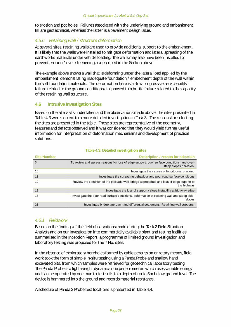
4.6 Intrusive Investigation Sites
Based on the site visits undertaken and the observations made above, the sites presented inTable 4.3 were subject to a more detailed investigation in Task 3. The reasons for selectingthe sites are presented in the table. These sites are representative of the geometry,features and defects observed and it was considered that they would yield further usefulinformation for interpretation of deformation mechanisms and development of practicalsolutions.
Table 4.3: Detailed investigation sites
Site Number Description / reason for selection3 To review and assess reasons for loss of edge support, poor surface conditions, and over-
steep slopes / erosion.
10 Investigate the causes of longitudinal cracking
11 Investigate the spreading behaviour and poor road surface conditions
12 Review the condition of the palisade wall, bridge approaches and loss of edge support tothe highway
13 Investigate the loss of support / slope instability at highway edge
15 Investigate the poor road surface conditions, deformation of retaining wall and steep side-slopes
21 Investigate bridge approach and differential settlement. Retaining wall supports.
4.6.1 FieldworkBased on the findings of the field observations made during the Task 2 Field SituationAnalysis and on our investigation into commercially available plant and testing facilitiessummarised in the Inception Report, a programme of limited ground investigation andlaboratory testing was proposed for the 7 No. sites.
In the absence of exploratory boreholes formed by cable percussion or rotary means, fieldwork took the form of simple in-situ testing using a Panda Probe and shallow handexcavated pits, from which samples were retrieved for geotechnical laboratory testing.The Panda Probe is a light-weight dynamic cone penetrometer, which uses variable energyand can be operated by one man to test soils to a depth of up to 5m below ground level. Thedevice is hammered into the ground and records material resistance.
A schedule of Panda 2 Probe test locations is presented in Table 4.4.

Ground Improvement for Khulna Soft Clay Soil
Page 29
Table 4.4: Schedule of locations for Panda Probe testing.
Site Site Name Area TestNumber
FinalDepth(mbgl)
EmbankmentHeight
(m)
Test LocationCo-ordinates
(N,E)
3 Assassuni Road287042008
123
4.74.74.5
1.21.21.1
22.59198,89.2120822.59184,89.2120922.59137,89.21211
10 Dumuria A Road247302001
123
4.93.74.5
1.82.01.6
22.80609,89.4235222.80494,89.4229022.80522,89.42314
11 Dumuria B Road247303003
123
4.54.24.8
1.61.60.9
22.7819,89.37757022.78181,89.3776922.78158,89.37742
12 Rupsa Road247752009
123
4.64.54.8
0.41.51.8
22.78648,89.6271322.78648,89.6269822.78714,89.62774
15 Terokhada A Road247942010
12
4.54.6
2.22.1
22.93618,89.6664722.93614,89.66649
13 Terokhada B Road247942003
123
4.64.64.6
5.05.05.0
22.91289,89.7049
22.91286,89.7049822.91294,89.70477
21 Mongla A & B Road201582003
1234
4.54.54.54.5
0.50.5
0.480.48
22.44176,89.6100122.44187,89.6099722.44218,89.6080922.44219,89.60775
4.6.2 Shallow hand-excavated pitsTo provide samples for laboratory geotechnical testing, 2-4 No. shallow hand excavated trialpits were formed at each of the 7 No. study sites. The trial pits were formed at both the topand bottom of the road embankments where conditions allowed. Soil samples wereretrieved from varying positions within the earthwork embankments. All samples retrievedwere sent to ProSoil Foundation’s laboratory in Dhaka to undergo geotechnical laboratorytesting.
A schedule of trial pit locations and depth is presented in Table 4.5 together with a scheduleof tests undertaken. Full details are provided in the Laboratory Test Report.

Ground Improvement for Khulna Soft Clay Soil
Page 30
Table 4.5: Schedule of samples taken for laboratory geotechnical testing.
*AL - Atterberg limits, MC - Moisture Content, OC - Organic Content, PSD - Gradings by sieveand hydrometer
SiteNumber
TrialPit
No.
Sample Depth(mbgl)
Locationof trial pit
onearthwork
Test Schedule Notes*
3 1. 0.3 Bottom AL, MC, PSD
2. 0.0 Top AL, MC, PSD
3. 0.3 Top AL, MC
10 1. 0.25 Top AL, MC, OC, PSD
2. 0.25 Top AL, MC, OC, PSD
3. 0.3 Top AL, MC, OC, PSD
11 1. 0.2 Bottom AL, MC, OC, PSD
2. 0.3 Top AL, MC, OC, PSD
3. 0.3 Top AL, MC, OC, PSD
12 1. 0.3 Top AL, MC, OC, PSD
2. 0.3 Bottom AL, MC, OC, PSD
3. 0.3 Top AL, MC, OC, PSD15 1. 0.3 Top AL, MC, PSD
2. 0.3 Top AL, MC, PSD13 1. 0.3 Top AL, MC, PSD
2. 0.3 Top AL, MC, PSD3. 0.3 Top PSD
21 1. 0.25 Top AL, MC, PSD
2. 0.25 Top None
3. 0.3 Top PSD
4. 0.3 Top PSD

Ground Improvement for Khulna Soft Clay Soil
Page 31
5 Field and Laboratory Testing
5.1 Field Testing Results
Panda probe results plots are provided by site in Appendix E. There are 21 No. plots for the 7No. sites which show cone resistance (in MPa) against depth for each test site. Table 5.1below provides a summary of results.
Table 5.1: Summary of Panda Probe Results.
SiteNumber
SiteName
TestNumber
FinalDepth(mbgl)
EmbankmentHeight
(m)
Summary of Penetration
3 Assassuni 1 4.7 1.2 Reduction in soil strength below roadsurface from 0 to 0.9 mbgl, before
steady increase to end of probe2 4.7 1.2 Sharp increase at shallow depth (in
road formation) followed by reductionin soil strength below road surface
from 0.1 to 0.9 mbgl, before steadyincrease to 2.0m where strength levels
to end of probe3 4.5 1.1 General drop in soil strength to
1.5mbgl, before rising to a steadyresistance value at 2.0mbgl.
10 DumuriaA
1 4.9 1.8 General slight rise in soil strength to2.0m then levels off to end of probe.
2 3.7 2.0 General slight rise in soil strength to2.0m then levels off to end of probe.
3 4.5 1.6 Reduction in soil strength below roadsurface from 0.3 to 0.9 mbgl, before
steady increase to end of probe11 Dumuria
B1 4.5 1.6 Variable strength within the
embankment, levelling off to aconsistent value from 1.0mbgl to the
end of the probe.2 4.2 1.6 General slight rise in soil strength to
end of probe.3 4.8 0.9 Reduction in soil strength below road
surface from 0 to 0.7 mbgl, beforesteady increase to 2.0m then levels off
to end of probe.
12 Rupsa 1 4.6 0.4 General slight rise in soil strength toend of probe. Zone of reduced
strength from 0.6 to 0.9mbgl2 4.5 1.5 Reduction in soil strength below road
surface from 0 to 0.7 mbgl, beforesteady increase to 3.0m then slight
reduction to end of probe.3 4.8 1.8 Reduction in soil strength below road
surface from 0.1 to 0.9 mbgl, beforesteady increase to 1.8 m then levels
off to end of probe.

Ground Improvement for Khulna Soft Clay Soil
Page 32
5.2 Interpretation of Probe Test Results
The results returned from the Panda Probe testing were remarkably consistent across the 7No. study sites. The cone resistance values are used to provide relative strength rather thanabsolute values.
For all 7 No. sites tested with the Panda Probe, a marked difference in cone resistance wasobserved between the placed embankment fill and the underlying natural ground. It wasclear that the embankment fills typically displayed a cone resistance of 1.5 MPa to 4 MPa. Inthe near surface extents of the embankment fill, cone resistance on occasions reached ashigh as 20 MPa, reflecting the presence of crushed brick content from highly degradedpavement or patch repairs. It is considered likely that the embankment fill underwent noformal compaction during placement, and has experienced little consolidation through self-weight, due to the low height of the embankments and frequent wetting and drying events.This is evidenced on some probes by a decreasing cone resistance towards the base of theembankment.
As the probe advanced into the underlying natural ground (typically between 1.5 and2mbgl), the resistance then rose steadily with depth to around 10 MPa from 3mbgl to 4.5mbgl. The steady rise in cone resistance with depth is likely to reflect both normalconsolidation of the sediments and also the effects of consolidation of the soils resultingfrom the embankment loading / overburden. Control probes to the side of the
SiteNumber
SiteName
TestNumber
FinalDepth(mbgl)
EmbankmentHeight
(m)
Summary of Penetration
15 TerokhadaA
1 4.5 2.2 Reduction in soil strength belowroad surface from 0.3 to 1.5 mbgl,
before steady increase to end ofprobe.
2 4.6 2.1 Slight reduction in soil strengthbelow road surface from 0.2 to 1.3
mbgl, before steady increase to endof probe.
13 TerokhadaB
1 4.6 5.0 Slight reduction in soil strengthbelow road surface from 0.0 to 2.4
mbgl, before sharp, then steadyincrease to end of probe.
2 4.6 5.0 Reduction in soil strength belowroad surface from 0.0 to 0.9 mbgl,
before levelling off to 2.0m, thensteady increase to end of probe.
3 4.6 5.0 General slight rise in soil strength toend of probe.
21 MonglaA & B
1 4.5 0.5 Reduction in soil strength belowroad surface from 0.1 to 0.4 mbgl,
before steady increase to 2.0 mthen levels off to end of probe.
2 4.5 0.5 General slight rise in soil strength toend of probe.
3 4.5 0.48 Reduction in soil strength belowroad surface from 0.2 to 0.7 mbgl,
before increasing to 2.0m, thenlevelling off to end of probe
4 4.5 0.48 Reduction in soil strength belowroad surface from 0.2 to 0.8 mbgl,
before slight increase to end ofprobe

Ground Improvement for Khulna Soft Clay Soil
Page 33
embankments were not possible due to flood waters / aquiculture, so the change in coneresistance as a result of embankment loading cannot be separately quantified.
5.3 Laboratory Testing Results
The testing of samples retrieved from the site works has been conducted in accordance withthe applicable American Society for Testing Materials (ASTM) standard for soil testing;
· ASTM D2487 - 11 Standard Practice for Classification of Soils for EngineeringPurposes (Unified Soil Classification System)
· ASTM D422-63 Standard Test Method for Particle-Size Analysis of Soils ASTM
5.4 Summary of laboratory testing undertaken
Laboratory test results from of the samples gathered during the Field & Laboratory Testingstage are presented in Appendix E. A summary of the test results is provided in Table 5.2through to Table 5.4.
Particle Size Distribution (PSD), Atterberg Limit testing, shrinkage limit, linear shrinkage andorganic content testing was scheduled for the samples retrieved from each trial pit.
Table 5.2: Summary of plasticity and organic test results
Site
No.
Tria
l Pit
No.
Sam
ple
Dep
th (m
bgl)
Visu
alC
lass
ifica
tion
USC
S*C
lass
ifica
tion
Liqu
id L
imit
LL (%
)
Plas
tic L
imit
PL (%
)
Shrin
kage
Lim
it SL
(%)
Line
arsh
rinka
ge L
s(%
)
Plas
ticity
Inde
x PI
(%)
Moi
stur
eC
onte
nt (%
)
Org
anic
Con
tent
(%)
3 1. 0.3 ClayCH - Fat Clay
52 28 - - 24 8 -
2. 0.0 NP NP - - NP 36 -
2b. 0.0 Silty SandCL - Lean Clay
27 13^ - - 14 - -
3. 0.3 62 19 11 26 43 36 -
10 1. 0.25 ClayCL - Lean Clay
47 21 14 18 16 26 6
1b 0.25 ClayCL – Lean Clay
44 23^ - - 21 - -
2. 0.25 ClayCL - Lean Clay
49 21 - - 28 27 9
3. 0.3 ClayCL - Lean Clay
with Sand
46 20 - - 26 13 7
11 1. 0.2 ClayCH – Fat Clay
with Sand
49 25 - - 27 28 2
2. 0.3 ClayCH - Fat Clay
58 25 - - 33 30 5
3. 0.3 ClayCH - Fat Clay
59 25 13 22 34 33 7
3b. 0.3 ClayCH – Fat Clay
79 27^ - - 52 - -
12 1. 0.3 ClayCL – Lean Clay
44 23 - - 21 25 7
2. 0.3 ClayCL – Lean Clay
48 20 - - 28 28 8
3. 0.3 ClayCH - Fat Clay
54 26 10 36 29 32 8

Ground Improvement for Khulna Soft Clay Soil
Page 34
* Unified Soil Classification System; LL – Liquid Limit; PL – Plastic Limit; SL – Shrinkage Limit; Ls – Linear Shrinkage;PL – Plastic Limit^ Results calculated using standard relationships, no laboratory results available**variability within the recovered sample – PSD identified as fine sand, and Atterberg limits as a Fat Clay.
Specific Gravity (Gs) testing was scheduled for the samples retrieved from trial pits, theresults are detailed in Table 5.3.
Table 5.3: Summary of specific gravity test results
* Unified Soil Classification System
Site
No.
Tria
l Pit
No.
Sam
ple
Dep
th(m
bgl)
Visu
alC
lass
ifica
tion
USC
S*C
lass
ifica
tion
Liqu
id L
imit
LL(%
)
Plas
tic L
imit
PL(%
)
Shrin
kage
Lim
itSL
(%)
Line
ar s
hrin
kage
L s (%
)
Plas
ticity
Inde
xPI
(%)
Moi
stur
eC
onte
nt (%
)
Org
anic
Con
tent
(%)
15 1. 0.3 ClayCL – Lean Clay
41 21 - - 20 19 -
2. 0.3 ClayCL – Lean Clay
42 21 - - 21 14 6
13 1. 0.3 ClayCL – Lean Clay
43 28 - - 17 17 -
2.** 0.3 ClayCH - Fat Clay
47 21 11 28 26 26 4.5
3. 0.3 Fine SandSM – Silty Sand
- - - - - - -
21 1. 0.25 ClayCH – Fat Clay
with Sand
54 21 - - 33 27 -
2. 0.25 - - - - - - -
3. 0.3 ClayCL – Lean Clay
41 24 - - 17 - -
4. 0.3 Fine SandSM - Silty Sand
- - - - - - -
SiteNumber
Trial PitNo.
Sample Depth (mbgl) Visual ClassificationUSCS* Classification
SpecificGravity
Gs
10 3 0.3 ClayCL - Lean Clay with Sand
2.83
11 3 0.3 ClayCH - Fat Clay
2.82
15 2 0.3 ClayCL – Lean Clay
2.80
13 3 0.3 Fine SandSM – Silty Sand
2.83
21 3 0.3 ClayCL – Lean Clay
2.69

Ground Improvement for Khulna Soft Clay Soil
Page 35
Particle Size Distribution (PSD) testing was conducted on 21 No. trial pit samples. The PSDplots are presented in Appendix E. A summary of the grain size distribution presented in theplots is give in Table 5.4.
Table 5.4: Summary of PSD results
Site TrialPit
Gravel %(75 to
4.75mm)
CoarseSand %(4.75 to
2.00mm)
MediumSand %
(2 to0.425mm)
FineSand %
(0.425 to0.075mm)
Silt %(0.075 to
0.005mm)
Clay %(<0.005mm)
3 1 0.00 0.00 0.00 1.75 46.38 51.86
3 2 0.00 0.11 2.45 28.25 53.56 15.64
10 1 0.00 0.00 0.00 6.00 53.08 40.92
10 1b 0.00 0.00 0.00 8.95 79.30 11.74
10 2 0.00 0.00 0.00 10.41 62.14 27.45
10 3 0.00 0.00 0.00 16.05 62.52 21.42
11 1 0.00 0.00 0.00 17.28 27.66 55.06
11 2 0.00 0.00 0.00 2.13 52.31 45.56
11 3 0.00 0.00 0.00 2.18 51.70 46.11
11 3b 0.00 0.00 0.00 2.60 46.36 51.04
12 1 0.00 0.00 0.00 5.97 74.68 19.35
12 2 0.00 0.00 0.00 6.73 52.25 41.02
12 3 0.00 0.00 0.00 9.78 31.18 59.04
15 1 0.00 0.00 0.00 14.73 59.82 25.45
15 2 0.00 0.00 0.00 5.45 79.00 15.55
13 1 0.00 0.00 0.00 9.99 68.75 21.27
13* 2 2.58 0.60 0.37 55.95 40.51 0.00
13 3 0.00 0.14 3.43 78.81 17.62 0.00
21 1 0.00 0.00 0.00 20.41 32.88 46.71
21 3 0.33 0.54 1.23 65.17 32.73 0.00
21 4 0.00 0.02 1.05 69.38 21.69 7.85
Minimum 0.00 0.00 0.00 1.75 17.62 0.00
Maximum 2.58 0.60 3.43 78.81 79.30 59.04
Average 0.14 0.07 0.41 20.86 49.82 28.72
*variability within the recovered sample – PSD identified as fine sand, and Atterberg limits as a Fat Clay.
The material is principally fine sand to clay; summarised as follows: -
· All trial pit samples contained Fine Sand, the proportion ranging between 2% and79% with an average of 22%
· All trial pit samples contained Silt size material, the proportion ranging between 18%and 80% with an average of 50%.
· Clay material was found in most samples, with the proportion ranging between 8%and 59% with an average of 29%.
· Variability within samples is observed, and within trial pits at the same site,illustrating localised changes in soil composition (typical of depositionalenvironment).

Ground Improvement for Khulna Soft Clay Soil
Page 36
5.5 Derivation of Geotechnical Parameters
The results of the Atterberg Limit testing are presented in the Tables below. The results arecategorised into Fat Clay and Lean Clay and the locations where these soils were found isidentified on Table 5.2. Some sites have identified only one clay soil type, and others haveboth e.g. Site 12.
In accordance with the Unified Soil Classification System (USCS), the Fat Clay has highplasticity (high volume change potential with varying moisture content) and Lean Clay haslow plasticity (low volume change potential with varying moisture content). The plasticityresults are presented on the A-Line chart of Figure 5.1. The Lean Clay plots as a clay ofintermediate plasticity on the chart (CI).
Figure 5.1: A-Line Plasticity Chart
The classification test results are summarised in Table 5.5.

Ground Improvement for Khulna Soft Clay Soil
Page 37
Table 5.5: Summary of plasticity test results
Fat Clay (CH) Max Min Count AverageMoisture content(mc) %
33 26 6 29.3
Liquid Limit (LL) % 79 47 8 56.5
Plastic Limit (PL) % 28 21 7 24.4
Shrinkage Limit (SL)%
13 10 3 11.3
Linear Shrinkage(Ls) %
36 22 3 28.7
Plasticity Index (PI)%
52 24 8 32.3
Liquidity Index (LI)^ 0.24 0.11 6 0.17* Results based on laboratory test results only^ Calculated using LI= (mc-PL)/PI
Lean Clay (CL) Max Min Count Average+Moisture content(mc) %
28 (28) 13 (13) 8 (8) 21.1 (21.1)
Liquid Limit (LL) % 49 (49) 27 (27) 13 (13) 43.4 (43.4)
Plastic Limit (PL) % 28 (28) 20 (20) 11 (9) 22.5 (22.1)
Shrinkage Limit (SL)%
22 (14) 14 (14) 2 (1) N/A
Linear Shrinkage(Ls) %
18 (18) 18 (18) 1 (1) N/A
Plasticity Index (PI)%
28 (28) 14 (14) 13 (13) 23.0 (23.0)
Liquidity Index (LI)^ 0.38 (0.38) -0.55 (-0.55) 8 (8) -0.01 (-0.01)* Results based on a combination of laboratory and literature review test results; results in brackets are based onlaboratory test results only.^ Calculated using LI= (mc-PL)/PI+Site 3, Trial Pit 1, 0.3mbgl sample moisture content discounted as anomalous
Shear vane, shear box or triaxial compressive strength tests on undisturbed samples arerequired to assess soil strengths. Such test results were not available at the time of writing.However, Liquidity Index (LI) values calculated from a relationship between moisturecontent, Plastic Limit and Plasticity Index can be used to provide an indication of theundrained shear strength of the soils. The natural moisture content of a soil relative to theliquid and plastic limits can be represented by means of the Liquidity Index LI, where
LI = mc – PL
PI
The LI will vary from 0 at their PL to 1 at their LL. The range of LI of -0.7 to 0.4 indicate thatthe moisture contents of the clays are typically closer to their PL than their LL.
The shrinkage limit (SL) of a soil is the water content, expressed as a percentage of theweight of the soil, at which further loss in moisture will not cause a decrease in its volume.Linear shrinkage is also calculated as part of the shrinkage limit test and this is defined as thedecrease in one dimension of a soil mass, expressed as a percentage of the originaldimension at the shrinkage limit. When considered in relation to the natural moisturecontent of in-situ soils, the Shrinkage Limit can be used to determine whether furthershrinkage of a soil will occur if allowed to dry out.
Comparison of the shrinkage limit test results for the Fat clays with their moisture contentvalues indicates that these soils are likely to have significant shrinkage potential. A single

Ground Improvement for Khulna Soft Clay Soil
Page 38
shrinkage limit test undertaken within the Lean clays again indicates the potential forshrinkage within these soils, however a single result is inconclusive.
An assessment of the extent of swelling potential should take account of the soilsmineralogy. However, typically clay soils with LL values of less than 35% and PI values of lessthan 12% are considered to have low swelling potential (US Army Corps of Engineers, 1990).Given the range of LL and PI values recorded the Fat and Lean clays are both considered tobe of medium to high swelling potential. In general, the results indicate higher swellingpotential within the Fat clays.
The plasticity index can be used to derive geotechnical parameters for the soil horizons usingstandard correlations presented in British Standard BS 8002:2015 Code of practice for earthretaining structures. Using the correlation presented in Table 2 of BS8002, for the PI resultspresented for the Fat Clay, the critical effective angle of friction, Ø’ would range between22° and 25°, with an average value of 24°. For the Lean Clay the effective critical angle offriction, Ø’, would range between 25° and 27°, with an average value of 26°.
In terms of engineering properties, the behaviour of the clay materials differs only slightlyand in situ variability and ability to define the different horizons in the field would indicatethat the more conservative geotechnical parameters e.g. for the Fat Clay, would be adoptedfor design.
Effective cohesion, c’, for the normally consolidated clay soils present would be 0kPa.
Organic content varied from 2-9% where tested and is a relatively small constituent unlikelyto have significant bearing on the material properties. Where organic material is identifiedin greater concentration, for example peat or decaying plant matter, the potential forsettlement of overlying soils is greater. It is known that significant organic clay and peatmaterial is present in the Khulna Region, and organic content of this material is noted inChapter 3.
5.6 Review of site specific parameters vs regional data from literature review
A review of the parameters determined from the site-specific investigation and that fromliterature has been undertaken, and it is observed that the parameters presented are similarand appear representative. This is with the exception of organic soils, that were notencountered in the test pits.
The grading test data from the literature review show that the soils in the study area aretypically fine-grained soils ranging between sandy silts (SM) to high plasticity clays (CH).Organic content is variable ranging from 0% to very high organic contents up to 71%.
The plasticity test data show similar results to site specific laboratory tests with the majorityof soils of low to high plasticity depending on their clay content. Although the data is limitedthere is no appreciable difference between the soils composition or moisture content overthe GL and 3m depth range and the underlying soils between 3m to 6m. Moisture contentsfrom the test sites are lower however, and this may be due to the shallow samples, or somedrying experienced during sampling.
Undrained shear strength test data are within the very soft to firm range over the upper GLto 3m layer. The 3m to 6m depth range show results in the very soft to soft range. The conetesting in the near surface of the foundation soil, together with the SPT N values fromexisting BH data supports this.

Ground Improvement for Khulna Soft Clay Soil
Page 39
Specific gravity data from the literature review of 2.50 to 2.77 are lower than the site-specific test results of 2.69 to 2.83, potentially illustrating more organic matter within thesoil samples tested and reported in existing literature.

Ground Improvement for Khulna Soft Clay Soil
Page 40
6 Development of Ground Models
6.1 General
For each of the sites where intrusive investigation was undertaken, the initial observationsfor the site together with an interpretation of the deformation mechanisms have beendeveloped into observational ground models, and these are presented in detail in AppendixF. A Technical Note was prepared by Mott MacDonald (27th March 2018) that provides adetailed explanation of the ground model development in relation to consolidation.
Using the data from the literature review, existing borehole records and field and laboratorytest data from the seven sites, a quantitative analytical ground model has been developed torepresent a typical site constructed in in a rural location on soft foundation soil. Theanalytical model allows deformation and stability to be considered and general observationsand recommendations to be made in later Chapters.
6.2 Review of key findings / indicators
Table 6.1 below lists the typical defects that were observed during the field visits at all sitesand indicates the probable primary and secondary causes that have been identified throughthe ground models developed and presented in Appendix F.
The defects are categorised as follows: -
· Embankment Defects;· Structure Defects and;· Pavement Defects.
The probable cause/mechanisms leading to the defect can also be categorised: -1) Deformation
a) Differential settlement
b) Total settlement
2) Stability
a) Bearing capacity
b) lack of lateral support (from foundation soil)
3) Floodwater (erosive action, pore-pressure increase)
4) Adjacent land use (aquiculture, other)
5) shrink/swell cycle (of soils)
6) Embankment construction (quality, materials)
7) Vehicle overloading
Items 1 and 2 can be partially or wholly attributed to soft foundation soil.

Ground Improvement for Khulna Soft Clay Soil
Page 41
Table 6.1: Summary of Typical defects in embankments, structures and pavements and probablecause/mechanism
Typical defect / indicator Probable Primary cause(s)* Probable Secondarycause(s)*
EmbankmentsThe side slopes are eroded /
oversteepEmbankment construction (quality,
materials)Adjacent land use
Floodwater erosive action
The embankment is spreading Embankment construction (quality,materials)
Shrink/swell cycle of embankment fill
Total settlementBearing capacity
The side slopes have failed(rotational failure through foundation
soil foundation)
Bearing capacity Embankment construction(quality, materials)Adjacent land use
Floodwater (pore-pressureincrease)
The side slopes have failed (withinembankment material)
Embankment construction (quality,materials, geometry)
Adjacent land useFloodwater (pore-pressure increase)
Vehicle overloadingShrink/swell cycle of
embankment fill
Leaning trees on slopes (indicative ofspreading / slope failure)
Embankment construction (quality,materials)
Shrink/swell cycle ofembankment fill
Bearing capacitySettlement / loss of alignment Total settlement Bearing capacity
Side slopes are eroded FloodwaterAdjacent land use
StructuresThere is a step between
bridge/culvert and approachDifferential settlement
Embankment construction (quality,materials)
Bearing capacityShrink/swell cycle of
embankment fill / structurebackfill
Culvert blocked / below water line Total settlementRetaining structure deformed Bearing capacity / lateral support from
foundation soilTotal settlement
Shrink/swell cycle ofbackfill
Abutments deformed / mis-alignment Bearing capacity Total settlementPavements
There are lateral cracks in thepavement
Vehicle overloadingEmbankment/pavement construction
(quality, materials)
Total settlementShrink/swell cycle of
embankment fill
The pavement is undulating /disturbed
Vehicle overloadingEmbankment/pavement construction
(quality, materials)
Total settlementBearing capacity
Shrink/swell cycle ofembankment fill
Wheel rutting of the pavement Vehicle overloadingEmbankment/pavement construction
(quality, materials)
Damaged shoulder Vehicle overloadingEmbankment/pavement construction
(quality, materials)
Adjacent land useFlooding
*probable causes in bold type are related to soft foundation soil
6.3 Analytical Ground Model
6.3.1 GeneralBased on the geometrical and geotechnical data collated, simplified models have been usedto assess the two principal factors (related to the foundation soil) of deformation andstability that contribute to the observed defects.

Ground Improvement for Khulna Soft Clay Soil
Page 42
To undertake modelling, a standardised ground profile has been adopted based on thefollowing: -
· Standard Penetration Test (SPT) N profile from existing BHs in proximity to Site 3,Site 10 and Site 11 have been used to determine undrained shear strength withdepth; these boreholes exhibit significant thickness of clay material.
· In addition, assuming no previous construction has occurred (no previousconsolidation of the soil) a normally consolidated soil profile has been considered.
· A 20m depth horizon has been considered, comprising very soft to soft clay.· For specific sites in Khulna, the soil profile will vary and is likely to be a combination
of alluvial soils, including clays, silts, fine sands and organic materials. A simplifiedmodel is developed where both Lean and Fat clay composition is considered, anddifferences noted.
· A 2m and 4m high embankment is modelled that is typical of rural roads· Only the influence of the foundation soil is considered e.g. self-settlement of
embankment and stability of the embankment slope itself is not included.· Only embankment construction is considered· Consolidation settlement only considered using elastic theory – creep settlement
likely to occur due to presence of organic material, but not quantified.· Undrained stability only considered – for embankment foundations, this is the most
critical case.
The outputs of the assessment provide: -
· Typical magnitude of deformation that would be expected for embankmentconstruction at 2 and 4m height
· The theoretical change in foundation soil material properties below theembankment as a result of the deformation (consolidation) caused by the loading(useful for assessment of ground treatment methods relating to surcharging ordensification).
· The factor of safety (in the undrained case) and hence stability that would beexpected for embankment construction at 2 and 4m height (at the end ofconstruction phase).
6.3.2 Deformation
6.3.2.1 Geotechnical ParametersIn support of the data from literature review presented in Chapter 3 and laboratory test datapresented in Chapter 5, Figure 1 of BS 8002:2015 has also been used to obtain a bulk unitweight for both a Fat and Lean Clay and embankment fill. Bulk unit weight of 17kN/m3 hasbeen assigned to the foundation soil (irrespective of whether Lean or Fat Clay) and torepresent embankment fill that has been compacted (although no field testing wasundertaken), a bulk unit weight of 19kN/m3 is adopted.
A Poisson’s ratio (v’) of 0.2 and undrained Poisson’s ratio (vu) of 0.5 has been assumed forboth a Fat and Lean Clay based on recommendations presented by Bowles (1997).Values for undrained shear strength, cu, have been derived from a SPT-N Value correlationusing equation [1] below from Tomlinson (1995).
Cu = f1 x SPT-N Value [1]

Ground Improvement for Khulna Soft Clay Soil
Page 43
Where f1 is a factor related to the plasticity index of the material, and can be derived withreference to Figure 1.5 of Tomlinson (1995). For the plasticity index values presented asmean for Fat and Lean Clay (32% and 23% respectively), the f1 values are 4.5 and 4.9.
A theoretical normally consolidated (NC) undrained shear strength, cu, profile has beenderived from a cu/σ’v ratio correlation with plasticity index shown by equation [2] belowfrom Craig (2004). This has been used in comparison to a cu derived from SPT-N Values.
Cu = 0.11 x σ’v + 0.0037 x Ip x σ’v [2]
Where σ’v is the effective vertical stress assuming groundwater at ground level. The profilesare shown on Figure 6.1 and Figure 6.2. Note that the SPT N derived Cu profile is the samefor both Figure 6.1 and Figure 6.2 as these are derived from the same source. Thetheoretical approach uses the average plasticity index for the soil types and the profile ishence different.
A design line for Young’s modulus, E, shown by was derived for both a site specificcorrelated cu and a theoretical cu shown by equation [3] below from Burland et al (1979)based on a strain level of 0.4%, representative of very soft clay reported in Bowles (1997).
Eu = M * CuE’ =
Where M is 400 for a strain level of 0.4% and v’ and vu is the drained and undrainedPoisson’s ratio.
6.3.2.2 Design methodologyA serviceability limit state approach has been adopted for the assessment of totalsettlement for the construction of an embankment on Fat and Lean Clay.
Vertical displacement calculations were undertaken with the use of Oasys Pdisp – Version19.3 Oasys (2017) to calculate total settlement based on elastic theory using Boussinesqanalysis method for constructing a 2m and 4m high embankment on 20m of soft soilcomprising Fat or Lean Clay with the stiffness profile determined from the process outlineabove.
An un-factored load representing a 2m and 4m high embankment of 38 and 76kN/m2
respectively, has been applied at ground level across an assumed embankment length of40m and width of 10m. Greater width of road influences (increases) the depth to which thedeformation is experienced.
Elastic theory has been used as opposed to one-dimensional consolidation theory, as this isappropriate for a thick layer of relatively homogenous (in terms of strength) alluvial materialas is common in Khulna Region.

Ground Improvement for Khulna Soft Clay Soil
Page 44
Figure 6.1: Undrained shear strength with depth determined from SPT N and theoretical normallyconsolidated approach (Fat Clay)

Ground Improvement for Khulna Soft Clay Soil
Page 45
Figure 6.2: Undrained shear strength with depth determined from SPT N and theoretical normallyconsolidated approach (Lean Clay)
6.3.2.3 Predicted SettlementThe results of maximum total settlement due to constructing a 2m and 4m embankment onFat and Lean Clay for stiffness parameters derived from a SPT-N value correlation and atheoretical correlation for a normally consolidated (NC) soil have been summarised in Table6.2 below.
Table 6.2: Predicted settlement for 2m and 4m embankments on standardised ground model.
Geology Cu profile Embankment Height(m)
Maximum totalsettlement (mm)
Fat Clay Cu derived from SPT-NValues
2 140
Fat Clay Theoretical NC Cu 2 148
Fat Clay Cu derived from SPT-NValues
4 281
Fat Clay Theoretical NC Cu 4 295
Lean Clay Cu derived from SPT-NValues
2 125
Lean Clay Theoretical NC Cu 2 156
Lean Clay Cu derived from SPT-NValues
4 312
Lean Clay Theoretical NC Cu 4 249

Ground Improvement for Khulna Soft Clay Soil
Page 46
6.3.2.4 Predicted increase in shear strengthA theoretical over-consolidated cu profile resulting from the construction of a 2m and 4membankment has been estimated from the addition of an increase in vertical stress withdepth due to a strip area (the embankment) carrying a uniform pressure to equation [1] andis shown by equation [4] and Figure 6.3.
Cu = 0.11 x (σ’v + σz) + 0.0037 x Ip x (σ’v + σz) [4]
Where σz is the vertical stress in the vicinity of a strip area carrying a uniform pressure for alinear stress-strain relationship derived from elastic theory reported in Craig (2004) byequation [5]
σz = [5]
Where q is the uniform pressure on a strip area, is the internal angle of uniform pressurewith depth and is the external angle of uniform pressure with depth.
Figure 6.3 illustrates the expected strength gain resulting from the construction of a 2m and4m high embankment on a foundation soil comprising typical Fat Clay. The strengthimprovement is a critical factor for ground improvement methods relying on consolidation,particularly where surcharging is used.
6.3.2.5 Ground improvementTo provide an indication of the performance of mass strength ground improvement methodson the theoretical model, vertical displacement calculations for the following scenarios havebeen modelled: -
· Ground improvement yields strength that is 2 times original soil strength· Ground improvement yields strength that is 4 times original soil strength· Ground improvement works are carried out to 6mBGL· Ground improvement works are carried out to 10mBGL· Original strength profile derived from SPT-N value correlation
Mass strength ground improvement would result from methods that increase the soildensity (for example sand compaction piles) or through reinforcement / partial replacement(for example cement columns) – see Chapter 9. In these cases, the improvement in soilstrength is dependent on the area improvement ratio, as, defined as the ratio of improvedarea to total area treated.
The maximum settlement for each of the above combinations has been analysed for a FatClay foundation soil and is presented in Table 6.3.
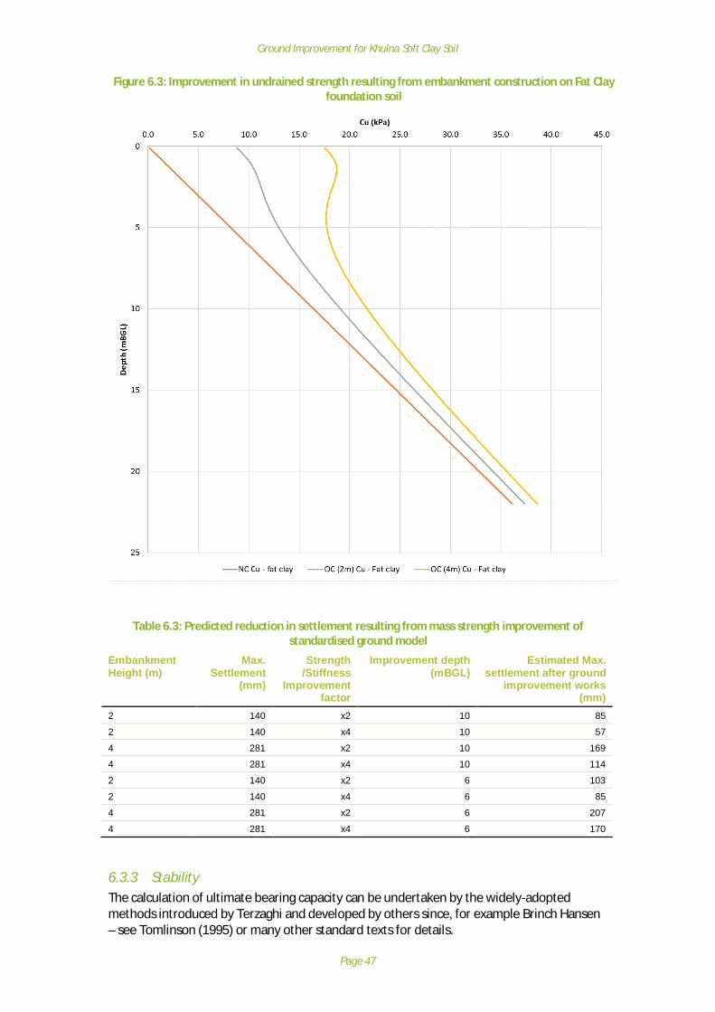
Ground Improvement for Khulna Soft Clay Soil
Page 47
Figure 6.3: Improvement in undrained strength resulting from embankment construction on Fat Clayfoundation soil
Table 6.3: Predicted reduction in settlement resulting from mass strength improvement ofstandardised ground model
EmbankmentHeight (m)
Max.Settlement
(mm)
Strength/Stiffness
Improvementfactor
Improvement depth(mBGL)
Estimated Max.settlement after ground
improvement works(mm)
2 140 x2 10 85
2 140 x4 10 57
4 281 x2 10 169
4 281 x4 10 114
2 140 x2 6 103
2 140 x4 6 85
4 281 x2 6 207
4 281 x4 6 170
6.3.3 StabilityThe calculation of ultimate bearing capacity can be undertaken by the widely-adoptedmethods introduced by Terzaghi and developed by others since, for example Brinch Hansen– see Tomlinson (1995) or many other standard texts for details.

Ground Improvement for Khulna Soft Clay Soil
Page 48
The ultimate bearing capacity of a foundation soil is calculated from an equation thatincorporates the geotechnical properties of the soil and geometry of the applied load. Theultimate bearing capacity is presented as a three-term expression incorporating the bearingcapacity factors: Nc, Nq and Ng, which are related to the angle of friction (f´) of thefoundation soil.
qu=c.Nc +qo.Nq + ½g.B . Ng
where: -c = cohesionqo = g . D (i.e. unit weight x depth)D = founding depthB = breadth of foundationg = unit weight of the soil removed
For drained loading, calculations are in terms of effective stresses with f ́> 0 and N c, Nq
and Ng are all > 0. When considering undrained conditions, the calculations are in terms oftotal stress and the term c, is the undrained shear strength, cu, and terms Nq = 1.0 and Ng =0. The resulting equation is:
qu = cu .Nc + qo
where: -Nc = 5.14 for f ́= 0
The simplified equation is often adopted where the undrained loading condition isconsidered more critical than the drained case, for example for construction ofembankments on soft clay. A more rigorous approach includes assessment of both the totaland effective stress to ensure both stability cases are addressed and the least conservativeadopted. This more rigorous approach was not possible within the constraints of theproject.
Using the undrained shear strength profile developed in Section 6.3 and illustrated on Figure6.1 and 6.2, it can be shown that the ultimate bearing capacity, for an undrained shearstrength of 8kN/m2 = 8 x 5.14 = ~40kN/m2. For a new embankment construction that is 2min height, the applied load if a unit weight of 19kN/m3 is used, is 38kN/m2. This indicatesthat the foundation soil is at or very close to failure.
Even if the foundation does not fail, the degree of deformation or settlement will be high anunlikely to be acceptable in terms of serviceability. For foundations, it is usual to apply afactor to the ultimate bearing capacity, typically 3, to provide an allowable bearing pressurethat will limit deformation to acceptable levels, giving very low values >15kN/m2. This drivesthe need for improved support, through either ground improvement or use of piles totransmit the load to depth.
6.4 Factors not related to soft foundation soil
The factors relating to soft foundation soil conditions are considered further in this report inChapters 8 to 10. The factors that are not related to foundation soil condition or groundimprovement are a significant contributory factor in the observational deformation modelsdeveloped and should not be overlooked. These are: -
· Inadequate pavement design and/or construction & maintenance.
Ground Improvement for Khulna Soft Clay Soil
Page 49
· The asphalt road surface sits atop a herringbone brick layer. These bricks push downeasily into the un-compacted embankment fill formation under vehicle load. Themovement of the numerous bricks under load results in often terrible reflectivecracking in the asphalt layer.
· The bricks are often of low strength and are susceptible to cracking and breakingunder load which further exacerbates the reflective cracking problem.
· The Lean Clay and Fat Clay of which the embankments are predominantlycomprised, have an intermediate to high volumetric change potential, and so canswell and contract with the regular variations in water level, thus affecting the roadpavement.
· Large and often overloaded vehicles are using the road and their weight isdeforming the pavement layers causing damage.
· Vehicles regularly drive along the edges of the road when passing each other, andthe action of the wheels moving on and off the edge of the pavement layer iscausing deep rutting and damage to the road edge which progressively worksinwards towards the centre of the road.
Issues with the embankment side slopes and side slope stability are also due to severalfactors:
· No or inadequate earthworks compaction· Inadequate design and/or construction of embankment slopes and reinforcement
e.g. toe wall.· Wave action is eroding the side slopes.· Human modification of side slopes to increase aqua-culture working area.· Regular variations in water level from aqua culture practice.· Trees lean outwards from the embankment slopes and as they grow and increase in
mass, lean further with potential to eventually uproot and damage the slopes.
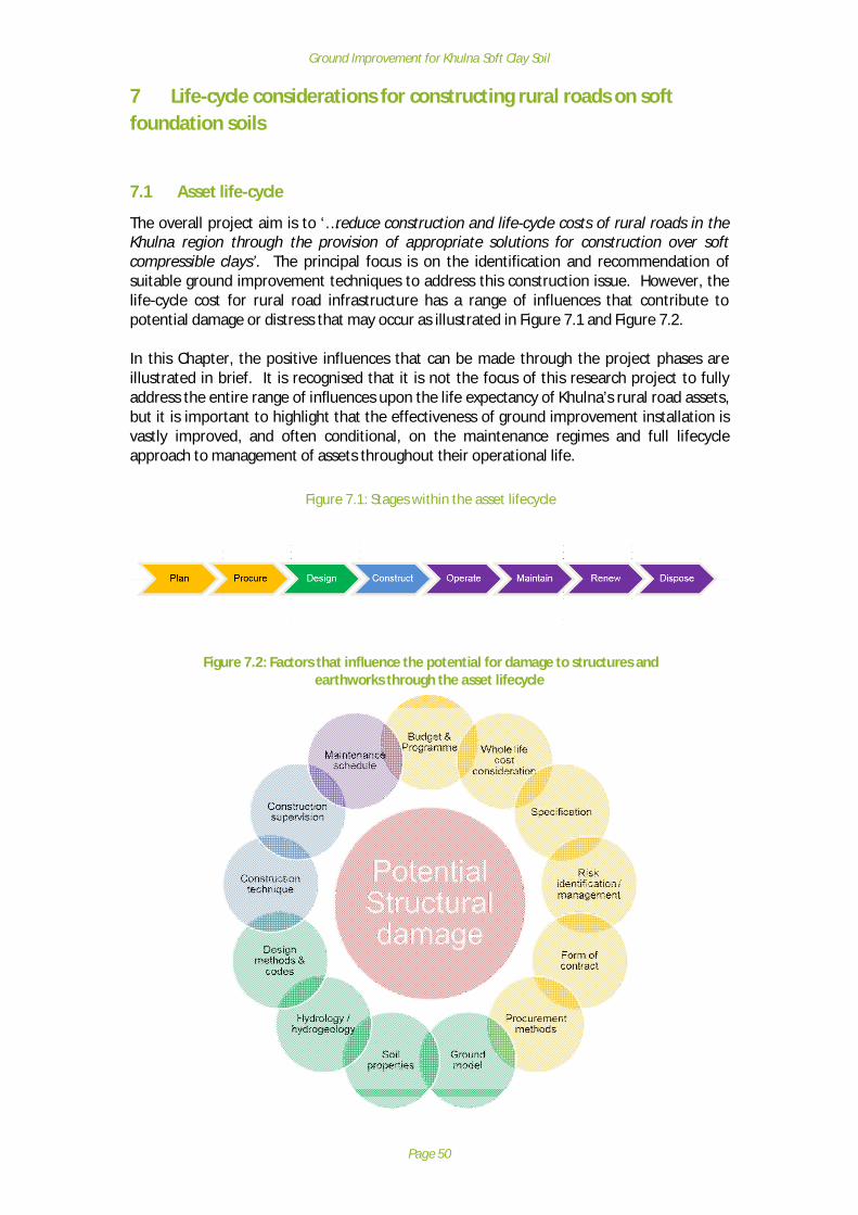
Ground Improvement for Khulna Soft Clay Soil
Page 50
7 Life-cycle considerations for constructing rural roads on softfoundation soils
7.1 Asset life-cycle
The overall project aim is to ‘…reduce construction and life-cycle costs of rural roads in theKhulna region through the provision of appropriate solutions for construction over softcompressible clays’. The principal focus is on the identification and recommendation ofsuitable ground improvement techniques to address this construction issue. However, thelife-cycle cost for rural road infrastructure has a range of influences that contribute topotential damage or distress that may occur as illustrated in Figure 7.1 and Figure 7.2.
In this Chapter, the positive influences that can be made through the project phases areillustrated in brief. It is recognised that it is not the focus of this research project to fullyaddress the entire range of influences upon the life expectancy of Khulna’s rural road assets,but it is important to highlight that the effectiveness of ground improvement installation isvastly improved, and often conditional, on the maintenance regimes and full lifecycleapproach to management of assets throughout their operational life.
Figure 7.1: Stages within the asset lifecycle
Figure 7.2: Factors that influence the potential for damage to structures andearthworks through the asset lifecycle

Ground Improvement for Khulna Soft Clay Soil
Page 51
7.2 Planning and Procurement
A considered approach to the asset lifecycle, at the earliest stages of project planning andprocurement, is considered essential to meeting the long-term aspirations that the assetowner has, and in particular minimising the costs and maximising useful service life.
Implicit in this is the planning of budget and programmes, in full consideration of theadditional risk and cost, both at construction and operations phase, associated with specificlocal risks – in this instance, construction on soft ground.
The significant investment of capital made during design and construction phase, may bewasted if consideration is not paid to appropriate maintenance, for which the cost isbudgeted and effectively implemented throughout the lifecycle of the infrastructure asset.
The establishment of a project geotechnical risk register (see example in Appendix H) isbeneficial to understanding the geotechnical related hazards and impacts, such thatinformed decisions relating to risk mitigation can be made through the whole asset lifecycle.For instance:
· Where ground conditions are poorly understood, the risk register should be used toinfluence the nature and quantity of ground investigation and laboratory testing;
· Where no ground investigation is planned or likely to be available, the impacts andconsequences must be understood, and mitigation measures, such as a more robustdesign, or increased long term maintenance will be understood from the outset;
The risk register provides a valuable focus for decision making throughout the life cycle ofthe project, and should be updated and reviewed on a regular basis to ensure the risks arebeing managed effectively, and in line with asset owner expectations.
One illustration of a common pitfall in planning and procurement for soft ground is wherecontracts will simply specify tighter movement tolerances. This is not always the best way tomanage the risk of soft ground, or realistic and achievable within the budgets andprogrammes available for construction, leading to higher costs for no improvement inlifecycle performance. Instead, setting sensible tolerances whilst understanding andplanning for maintenance requirements to manage serviceability levels in the long term canbe a more pragmatic and achievable approach.
Similarly, in the procurement phase - setting challenging contractual and programmerequirements will almost certainly not lead to a successful outcome on a project where theground conditions are probably poorly understood. Working together to meet thechallenges and being flexible in how difficult situations can be overcome may be moreexpensive in the design and construction phase, but will lead to significant benefits duringoperations and maintenance, most notably in reducing the long-term liability ofmaintenance and renewal that is likely to prove more expensive over a shorter life for theasset.
Note, procurement can relate to design and/or construction services depending on how aproject is delivered.

Ground Improvement for Khulna Soft Clay Soil
Page 52
7.3 Design Phase
Once an adequately planned and procured project moves into the design phase, theparticular characteristics of the site need to be understood to a level that manages theproject risks in line with asset owner expectations. For example, for sites in the Khulnaregion where consideration of ground conditions might have a high impact on theconstruction costs and asset lifecycle:
· Where field investigations and analyses show that the impact of overall groundmovements is only slight, there is little point in developing a sophisticated groundmodel and analysis;
· Where there are highly prescriptive specifications associated with movementtolerance on soft ground, basic trial pits and basic laboratory testing to support thedesign process, will not adequately manage the associated ground risks, withresultant outcomes of serviceability issues or asset failure. In this instance, a moresophisticated approach would be required
With this in mind, Figure 7.3 demonstrates a design process that adequately manages therisk associated with soft ground. This is also included as a flow chart in Figure 10.3 inChapter 10.
Figure 7.3: Design Phase – Management of Risks associated with Soft Ground
7.3.1 Desktop StudiesFor all projects, and particularly ones where ground conditions are envisaged to beproblematic, investing in the early stages of a project, through literature review, desk study,observational site visit and ground investigation is strongly recommended. These activitiesrepresent a small part of the project cost, but contribute significantly to long term riskmitigation that is required to predict, prevent or manage future ground and structuralmovement.

Ground Improvement for Khulna Soft Clay Soil
Page 53
7.3.2 Ground Investigation and Laboratory TestingDeveloping a good observational ground model is dependent on the quality of the groundinvestigation contractor, their plant, sampling methods and transportation together with thelaboratory testing. The quality of the ground information received from a borehole log orfrom the laboratory is in itself a risk that needs to be managed appropriately. Greaterinvestment in high quality ground investigation services is required for construction projectsor techniques that are more complex or high profile. It is recognised that sophisticatedground investigation is not routine for rural road projects, but the long-term projectoutcomes will improve if this stage can be completed.
7.3.3 Methodologies for managing Soft GroundThere are many available design and construction methods that could be suited to managingrisks of soft ground, for which the following factors need to be taken into consideration:
· Ground Improvement: Cost variance between different ground improvementoptions can be high, for example pre-loading vs installation of sand compactionpiles;
· Programme: For short or time-critical programmes, the costs are likely to be higher,as cheaper options such as pre-loading may not be possible;
· Specifications (Tolerance): Where construction tolerance is small or been specifiedas very tight the costs will be higher, as more robust solutions are needed;
· Ground Investigation: a technique that requires a great deal of ground knowledgeto support design, should not be selected where knowledge of the foundation sub-soil is lacking;
· Lifecycle Expenditure: Lower initial capital expenditure (CAPEX) solutions, usuallyhave a proportionally higher operational expenditure (OPEX) to maintain long termserviceability. That is perfectly acceptable as long as these residual risks areunderstood, budgeted for, and implemented in operations and maintenanceregimes.
In the soft soil environment, for organic rich soils, where there is often an active process ofsecondary compression (caused by creep settlement), well beyond the primary soilconsolidation phase and sometimes throughout the life of a structure, a prior knowledge ispowerful – meaning that if the structure is going to move, this can be planned for,throughout design, construction and maintenance.
It is through an understanding of the ground risks, the mitigation potential and relativeadvantages/disadvantages of various techniques, and the design optioneering process itself,that the final design can be prepared with a degree of confidence. The design phase is wherethe principal decisions are made that will manage risk through the asset life, and the successof a project in these terms is often entirely dependent on how thoroughly that phase hasbeen conducted. The overall influences that influence selection of ground improvementmethods at design stage are typically: -
· Importance of the road to transport network;· Sensitivity of the structure to deformation e.g. earthwork vs structure· Geology at the site· Certainty of the ground model· Applicability of the method to site conditions and constraints· Availability of plant and supervision
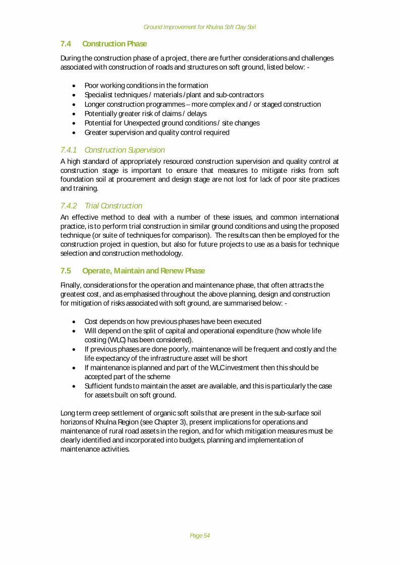
Ground Improvement for Khulna Soft Clay Soil
Page 54
7.4 Construction Phase
During the construction phase of a project, there are further considerations and challengesassociated with construction of roads and structures on soft ground, listed below: -
· Poor working conditions in the formation· Specialist techniques / materials /plant and sub-contractors· Longer construction programmes – more complex and / or staged construction· Potentially greater risk of claims / delays· Potential for Unexpected ground conditions / site changes· Greater supervision and quality control required
7.4.1 Construction SupervisionA high standard of appropriately resourced construction supervision and quality control atconstruction stage is important to ensure that measures to mitigate risks from softfoundation soil at procurement and design stage are not lost for lack of poor site practicesand training.
7.4.2 Trial ConstructionAn effective method to deal with a number of these issues, and common internationalpractice, is to perform trial construction in similar ground conditions and using the proposedtechnique (or suite of techniques for comparison). The results can then be employed for theconstruction project in question, but also for future projects to use as a basis for techniqueselection and construction methodology.
7.5 Operate, Maintain and Renew Phase
Finally, considerations for the operation and maintenance phase, that often attracts thegreatest cost, and as emphasised throughout the above planning, design and constructionfor mitigation of risks associated with soft ground, are summarised below: -
· Cost depends on how previous phases have been executed· Will depend on the split of capital and operational expenditure (how whole life
costing (WLC) has been considered).· If previous phases are done poorly, maintenance will be frequent and costly and the
life expectancy of the infrastructure asset will be short· If maintenance is planned and part of the WLC investment then this should be
accepted part of the scheme· Sufficient funds to maintain the asset are available, and this is particularly the case
for assets built on soft ground.
Long term creep settlement of organic soft soils that are present in the sub-surface soilhorizons of Khulna Region (see Chapter 3), present implications for operations andmaintenance of rural road assets in the region, and for which mitigation measures must beclearly identified and incorporated into budgets, planning and implementation ofmaintenance activities.
Ground Improvement for Khulna Soft Clay Soil
Page 55
8 Current Guidance for Design & Construction of Rural Roads
8.1 General
The Government of the People’s Republic of Bangladesh provide a number of specificationsand guidance documents for rural road applications as follows: -
1. Local Government Engineering Department (1999). Road Pavement Design Manual2. Planning Commission (2004), Road Design Standards, Standard Designs and Costings
for Zila, Upazila and Union Roads, Bridges and Culverts (2004)3. Local Government Engineering Department and Japan International Cooperation
Agency (2005), Road Design Standards, Standard Designs and Costings for Zila,Upazila and Union Roads, Bridges and Culverts
4. Local Government Engineering Department (2004). Technical Specification forBridges on the Upazila and Union Roads.
5. Local Government Engineering Department (1999). Standard Specifications forFeeder Road Type-B & Rural Road Type-R1 under LGED.
The documents provide design guidance for the construction of rural road embankmentsand structures, including material specification, slope angles and includes numerousstandard details for use in construction scenarios. With the exception of guidance onpreparation of foundation soil in (3) and (5) e.g. grubbing and compaction, there is nospecific guidance provided on treatment methods for use when the foundation soil strengthis low. Also, no design criteria for settlement / differential settlement was noted.
Due to the flat topography in most of Bangladesh, the abundance of water courses andregular flooding, rural roads are generally built on embankments. The geomorphologydictates that the embankments are low, and most observed are 1 to 2m high with someearthworks up to 5m where adjacent to bridge structures e.g. bridge approachembankments. The design guidance concentrates mainly on the new build of suchearthworks but also provides direction where dealing with remedial treatments andearthworks widening.
The following Table 8.1 presents a summary of the key geotechnical related points providedin documents (1) to (4), categorised as follows: -
· General· Ground Investigation· Sub-grade assessment· Earthwork Materials· Construction· Slope angle· Slope protection· Drainage· Widening
Geotechnical related elements in document (5) are largely the same as in (3); comment ondocument (5) is not given in the table below to avoid duplication.

Ground Improvement for Khulna Soft Clay Soil
Page 56
Table 8.1: Summary of key geotechnical points in LGED Guidance and Specifications
Category (1) Local Government EngineeringDepartment (1999)
(2) Planning Commission(2004)
(3) Local Government EngineeringDepartment and Japan International
Cooperation Agency (2005)
(4) Local Government EngineeringDepartment (2004)
General Settlement should always be expected, especially onapproaches to bridges where embankments are
higher..
Four categories of road project withdefinitions. (i) Reconstruction, (ii)
New Road Construction, (iii)Widening and (iv) Strengthening.
Typical costs (at 2004) provided forroad categories above + slope
protection works.Six design standards for pavementsdetailed for different traffic and axleload scenarios – not dependent onroad classification e.g. Zila, Upazila,
Union and Village.Standard geometries for bridges
included.Typical plan & elevation (Fig 6) ofbridge approaches and slopes for
approaches provided (angles /protective measures)
It is noted that where embankments are to be builtin swamps or water, that swampy ground will be
displaced, typically by sand as directed by theEngineer. It is also stated that the original ground
surface (the foundation soil) needs preparationand compaction to a specified limit (95%MDD)
This is a works specification document.Description of piling methods for constructing
foundations are included.
GroundInvestigation
Section 2.7 states that confirmatory sub-soilinvestigations shall be carried out at each bridge
foundation. Testing and sampling (bothdisturbed and undisturbed) together with
Standard Penetration Testing (SPT) ‘shall’ becarried out. Includes tests for strength and
deformation of soils in addition to classificationtests.
Sub-gradeassessment
Recommended thicknesses for improved sub-gradelayers (ISG) are given where lower CBR values are
recorded (between 200 and 450mm).Overseas Design Note 31 (TRL) is included in
Appendix C that gives comprehensive guidance onassessment of CBR for road purposes.
Recommended ISG are given instandard pavement details.
Appendix D also gives ISG layerthicknesses depending on CBR of
sub-grade. ISG is 450mm for CBR2% and 200mm for CBR = 5%.
ISG layers are to have Plasticity Index <6%. N/A
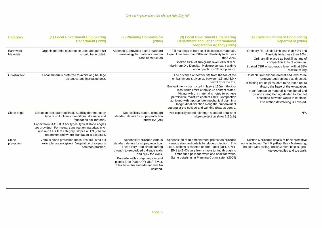
Ground Improvement for Khulna Soft Clay Soil
Page 57
Category (1) Local Government EngineeringDepartment (1999)
(2) Planning Commission(2004)
(3) Local Government EngineeringDepartment and Japan International
Cooperation Agency (2005)
(4) Local Government EngineeringDepartment (2004)
EarthworkMaterials
Organic material must not be used and pure siltshould be avoided.
Appendix D provides useful standardterminology for materials used in
road construction
Fill materials to be free of deleterious materials.Liquid Limit less than 50% and Plasticity Index less
than 20%.Soaked CBR of sub-grade level >3% at 95%
Maximum Dry Density. Moisture constant at timeof compaction ±5% of optimum.
Ordinary fill - Liquid Limit less than 50% andPlasticity Index less than 20%.
Ordinary fill placed as backfill at time ofcompaction ±5% of optimum.
Soaked CBR of sub-grade level >4% at 95%Maximum Dry
Construction Local materials preferred to avoid long haulagedistances and increased cost.
The distance of borrow pits from the toe of theembankment is given as between 1.5 and 3.0 x
height from the toe.Embankment constructed in layers 150mm thick or
less within limits of moisture content stated.Mixing with dry material is noted to achieve
permissible moisture content limits. Compactionachieved with ‘appropriate’ mechanical plant in a
longitudinal direction along the embankmentstarting at the outside and working towards centre.
‘Unstable soil’ encountered at bed level to beremoved and replaced as directed.
For footing not on piles, care to be taken not todisturb the base of the excavation.
Poor foundation material is mentioned andground strengthening alluded to, but not
described how this would take place.Excavation dewatering is covered.
Slope angle Selection procedure outlined. Stability dependent ontype of soil, climatic conditions, drainage and
foundation soil material.For different AASHTO soil types, typical slope anglesare provided. For typical construction materials in A-
4 to A-7 AASHTO category, slopes of 1:3 (v:h) arerecommended where inundation is expected.
Not explicitly stated, althoughstandard details for slope protection
show 1:2 (v:h)
Not explicitly stated, although standard details forslope protection show 1:2 (v:h)
N/A
Slopeprotection
Various slope protection measures are listed butexample use not given. Vegetation of slopes is
common practice.
Appendix H provides variousstandard details for slope protection.
These vary from simple turfingthrough to embedded palisade walls
and brick toe walls.Palisade walls comprise piles and
planks (see Plate UPR-UNR-EM1).Piles have 2m embedment and 1m
upstand.
Appendix on road embankment protection providesvarious standard details for slope protection. The
11No. options presented on the Plates (UPR-UNR-EM1 to EM3) vary from simple turfing through to
embedded palisade walls and brick toe walls.Same details as in Planning Commission (2004)
Section 6 provides details of bank protectiveworks including; Turf, Rip-Rap, Brick Matressing,
Boulder Matressing, Brick/Cement blocks, geo-jute geotextiles and toe walls

Ground Improvement for Khulna Soft Clay Soil
Page 58
Category (1) Local Government EngineeringDepartment (1999)
(2) Planning Commission(2004)
(3) Local Government EngineeringDepartment and Japan International
Cooperation Agency (2005)
(4) Local Government EngineeringDepartment (2004)
Drainage Importance of drainage on performance of sub-gradeand embankment fill is highlighted. Moisture content of
sub-grade and embankment fill changes due to anumber of causes.
(i) Seepage of water into the subgrade(ii) Rise or fall in the level of water-table.
(iii) Percolation of water into the subgrade throughcracks in road surface.
(iv) Transfer of moisture by capillary action from lowerlayer of soil.
(v) Transfer of moisture from shoulder to thepavement edges.
As most of the rural roads have low freeboard duringrainy season, the water table rises and comes very
close to the pavement. As a result, the stability of thesubgrade is reduced. Typical drainage layouts to
address this are provided, although it should benoted that drainage cannot prevent inundation from
sever flood events experienced in Bangladesh.
The importance of cross-drainage ishighlighted to mitigate waterlogging
and flooding of embankments.Typical length of drainage ‘gaps’ per
km of road are given.
Widening Benches should be formed in the existing earthworkto key in the new portion
Benches to be 300mm high and 600mm wide.Materials excavated from benches may be used
subject to compliance with materials specification.Typical standard details for road widening of
Upazila and Union Roads given in Plates UPR-EW-WD1 and UNR-ES-WD1. Plates show
benching and overfilling at edges (to be trimmedon completion)

Ground Improvement for Khulna Soft Clay Soil
Page 59
9 Ground Improvement Techniques for Soft Soil in Khulna Region
9.1 Overview
The techniques that are described below and summarised in the accompanying Tables 9.1 to9.6 are those that are considered either (a) technically feasible and (b) within the likelybudget for rural road construction. From the literature review, and discussions with localstakeholders, the techniques are mostly in use in Bangladesh, although not necessarily forthe rural road application. The ground improvement techniques considered here are: -
· Excavate and Replace / Displacement· Sand Compaction Pile· Sand Drain (with surcharge)· Prefabricated Vertical Drains (with surcharge)· Geotextile basal reinforcement· Cement Columns
Cement columns and Geotextile basal reinforcement are included here as they representsignificant benefits, although the use in Bangladesh is limited. Some research has beenundertaken and this is discussed. Other potential techniques that have benefits but limitedresearch, for example fibre reinforced soil (with jute or shredded plastic) are presented inChapter 11.
It is notable that there are no clear design criteria for settlement / differential settlement forroads and structures within the current LGED design guidance for rural road construction
Ground improvement by displacement e.g. with sand/rock would commonly be used in thesoftest of soils or swamp conditions as indicated in LGED guidance (see Chapter 8). Thesemethods are only briefly considered here as they are outside the scope of the research.
9.2 Sand Compaction Pile (SCP)
9.2.1 Methodology and typical useSand is fed into the ground through a casing pipe and compacted by means of a hammer orvibration. The SCP technique can be used effectively in loose sand and soft clay materials toaffect an improvement in the stiffness and strength of the soil mass. For sands, theimprovement in the ground is through densification of the mass to increase density, stabilityand deformation characteristics. For clays, the introduction of SCPs reinforces the softfoundation soil with columns of stiffer materials, improving overall strength and stability.For discrete thicknesses of soft foundation soil, with a competent layer or bedrock atrelatively shallow depth, the SCPs are taken down to this depth and this is termed ‘fixed typeimprovement’ Kitazume (2005). Where competent ground is too deep or engineering plantcannot reach this depth, the technique is termed ‘floating-type improvement’. The former ispreferred as settlement is less. Patterns for the SCP can be square, triangular or rectangular.
For earthworks, the introduction of SCP is most useful for reducing settlement andincreasing the bearing capacity of the soil. For structures, SCP can be used at transitions e.g.approach embankments, to limit differential settlement.

Ground Improvement for Khulna Soft Clay Soil
Page 60
A more extensive review of research and experience of the technique is included in thepreviously submitted Inception Report.
9.2.2 Design GuidanceGuidance on design methods is included in Kitazume (2005). Generally, the effectiveness ofthe technique increases as the replacement area ratio, as, increases. The replacement areais defined by the ratio of the replacement sand area and the overall area being treated.Clearly, the greater the sectional area of sand compared to the overall treatment area, thehigher the ratio and greater influence the sand component has on ground characteristics.The soils strength, and resulting bearing capacity, is determined from a compositecalculation using Terzaghi’s theory (See Section 6.3), whereby the capacity of the clayportion and sand portion are separately calculated and then, using the replacement arearatio, as, the combined bearing capacity is given. It is reported that in Bangladesh, a sandvolume that is 4 times the volume of the pipe casing is introduced, producing an SCP that isapproximately twice the casing diameter.
The deformation characteristics and resulting settlement under load is also determinedusing the replacement area ratio, as, to determine a settlement reduction factor, ß. Thesettlement reduction factor is applied to the settlement value determined for unimprovedsoil through one-dimensional consolidation or elastic theory. The settlement factor reducesas the replacement area ratio increases.
Alamgir and Chowdhury (2004) reported on the improvement in strength gained from theinstallation of 200mm sand piles 8-9m in length, 0.75m spacing in a square arrangement toprovide support to a river regulator structure. Pre- and post- construction SPTdemonstrated an increase in N value, indicative of strength, of up to 3-4 times original.Mixed sand/stone (fine/medium gravel) columns can also be used, with reported greaterstrength.
An overall summary of the technique is provided in Table 9.1 below.
Table 9.1: Sand Compaction PileGround ImprovementTechnique
Sand Compaction Pile (Hammer)
References used Kitazume (2005), Alamgir and Chowdhury (2004), Harada et al (2015)
Purpose · To increase strength and stiffness of the foundation soil leading toimproved bearing capacity and reduction (not elimination) of totaland differential settlement.
· Improvement in properties comes from combination of: -o direct support by SCP,o replacing proportion of soft clay foundation soil with
sand (greater proportion = better improvement),o the action of densification as the SCP is formed
(although this is better in sandy foundation soils) and;o controlled consolidation and hence increase in stiffness
of soil mass.· Where no competent horizon to provide end bearing, the SCP
could be used to improve bearing capacity of the soil, althoughsettlement would still occur.
Application · To provide support to shallow bridge foundations and culverts· To provide support to bridge approach embankments (where
bridge foundations are piled or supported on SCP) to limit impactsof differential settlement between earthworks and bridge structure
· To improve bearing properties of foundation soil below generalearthworks that could lead to reduced construction programme
· To reduce total settlement of general earthworks to reduce overallmaintenance requirements.

Ground Improvement for Khulna Soft Clay Soil
Page 61
Ground ImprovementTechnique
Sand Compaction Pile (Hammer)
Design and ConstructionConsiderations
· Current methods limit depth of construction to 10-12m, typicallyshorter.
· In Khulna Region, this is typically installed through a 200-300mmdiameter pipe to create a 400-600mm diameter SCP (4 timesvolume increase through ramming action)
· Spacing typically 0.7-0.9m in a triangular or square pattern· Depth of soft soil – if >10-12m, current implementation methods
will reduce effectiveness (floating vs fixed)· Geometry dictates improvements to strength and stiffness e.g. as
spacing between SCP reduces, bearing capacity increases andsettlement reduces proportional to the volume of foundation soilreplaced by SCP. This has a cost implication. The more that isspent, the greater the improvement. Typically for clay foundationsoils, the replacement ratio is 30% or greater of the original soilmass.
· Methods for quality control of installation need to be specified.· Availability / source of sand – significant volumes required.· Properties of sand and foundation soil materials, together with
geometry of SCP and soil profile is required for design· Straightforward design process using traditional soil mechanics
theory subsequently factored to account for proportion of originalsoil replaced. Simple design charts could be developed.
Advantages · Proven use in the Region, including labour and plant· Provides direct support from the SCP and densification of the
surrounding ground· Permeable nature of SCP provides a drainage path to expedite
consolidation settlement
Disadvantages · Depth limitation may lead to reduced effectiveness in deeper softsoil horizons
· Design requires knowledge of the foundation soil properties andgeometry
· Requires a supply of clean sand· Relatively more skilled labour required· Relatively more specialist plant required· Noisy (vibrating option reduces the hammering action but more
specialised plant)· Where replacement ratio is higher, ground heave and waste
material may result.· Quality control is difficult / requires supervision
9.3 Sand Drain with surcharge loading
9.3.1 Methodology and typical useThe sand drain (SD) is installed in the same manner as the SCP with sand fed into the groundthrough a casing, but the degree of compaction is significantly less. A sand volume of twicethe pipe casing is reported from discussions in Bangladesh.
The method is used to expedite consolidation of the soft foundation soil, so that bearingcapacity during construction can be increased and settlement during operation be reduced.The introduction of vertical drains reduces the length of the drainage path within thefoundation soil, that might otherwise be upwards to the surface only. The rate ofconsolidation can be influenced by the length of the drainage pathways (more drains meansshorter drainage paths), and the applied surcharge loading.
Dhar et al (2011) reports that for an equivalent pattern layout, SD of 200mm diameter, aremore expensive than prefabricated vertical drains (PVDs), but are more effective in terms ofrate of consolidation.

Ground Improvement for Khulna Soft Clay Soil
Page 62
A more extensive review of research and experience of the technique is included in thepreviously submitted Inception Report.
9.3.1 Design GuidanceGuidance on design methods is included in Dhar et al (2011). The amount of settlement isdetermined from one dimensional consolidation theory (or elastic theory as presented inChapter 6 of this report). The time for consolidation can be determined using the theory ofconsolidation by radial drainage presented by Hansbo (1960, 1979). Determination of timefor consolidation requires the geometry and permeability of the vertical drain, and area tobe drained (by each drainage element), the coefficient of horizontal consolidation andhorizontal permeability (of the in situ soil), Ch and kh, and details of the zone of disturbancecreated during construction as a result of soil smear (geometry and permeability).
A surcharge loading of 1.2 times future effective stress was suggested by Seah et al (2011) tolimit settlement in operation, but this must be balanced against initial bearing capacity, andmay require staged construction up to the final surcharging load. As consolidation proceeds,the bearing capacity of the soil increases as demonstrated in Chapter 6.
An overall summary of the technique is provided in Table 9.2 below.
Table 9.2: Sand Drain (with surcharge loading)Ground ImprovementTechnique
Sand Drain (with surcharge loading)
References used Dhar et al (2011), Hansbo (1960, 1979)
Purpose · To increase strength and stiffness of the foundation soil leading toimproved bearing capacity / settlement properties through soilconsolidation prior to
· Improvement in properties comes from combination of: -o controlled consolidation using surcharge loading and
hence increase in stiffness / strength of soil mass oncompletion of surcharging period.
Application · To improve ground for bridge approach embankments (wherebridge foundations are piled or supported on SCPs) to limitimpacts of differential settlement between earthworks and bridgestructure
· To improve bearing properties of foundation soil below generalearthworks
· To reduce total settlement of general earthworks (followingconsolidation phase) to reduce overall maintenance requirements.
Design and ConstructionConsiderations
· Current methods limit depth of construction to 10-12m· In Region, this is typically installed through a 200-300mm diameter
pipe to create a 300-450mm diameter SD (2 times volumeincrease – lightly rammed)
· Depth of soft soil – if >10-12m, current implementation methodswill reduce effectiveness of SDs
· Spacing typically 0.7-0.9m in a triangular or square pattern· Geometry dictates improvements to strength and stiffness e.g. as
spacing between SD reduces, consolidation is more effective(drainage paths shorter) and volume reduction / strength gain isachieved more rapidly.
· Requires sand blanket at embankment formation level· Methods for quality control of installation need to be specified.· Availability / source of sand – significant volumes required.· Properties of sand and foundation soil materials, together with
geometry of SD and soil profile is required for design· Straightforward design process using traditional soil mechanics
theory to determine final settlement and stiffness. Simple designcharts could be developed.

Ground Improvement for Khulna Soft Clay Soil
Page 63
Ground ImprovementTechnique
Sand Drain (with surcharge loading)
Advantages · Proven use in the Region, including labour and plant· Provides improved strength and stiffness of the combined soil
mass once consolidation has taken place
Disadvantages · The improvement takes time to develop leading to increasedconstruction programme
· Improvement in soil properties not as great as for SCP method.· Depth limitation may lead to reduced effectiveness in deeper soft
soil horizons· Can be ineffective in layered or laminated soft soil profiles due to
smearing and blockage of horizontal in situ drainage paths· Design requires knowledge of the foundation soil properties and
geometry to determine time for surcharging to design strength /stiffness.
· Requires a supply of clean sand· Relatively more skilled labour required· Relatively more specialist plant required· Noisy
9.4 Prefabricated Vertical Drain (and Jute Drain) with surcharge loading
9.4.1 Methodology and typical usePrefabricated vertical drains (PVDs) are installed with a mandrel pushed down into the softsoil. As for the SD, the method is used to expedite consolidation of the soft foundation soil,so that bearing capacity during construction can be increased and settlement duringoperation be reduced. The method has been widely used on construction projects aroundthe world including Bangladesh, but would rarely be implemented on rural roads due to therequirement for more specialist equipment and materials than the SD technique.Notwithstanding this, the PVD technique is a viable solution and could be implemented overSDs where programme was shorter.
A more extensive review of research and experience of the technique is included in thepreviously submitted Inception Report.
9.4.2 Design GuidancePVDs evolved from the SD technique, and the theory is much the same as for SD (see Section9.3). Guidance on design methods is included in Dhar et al (2011) and Seah (2005). AChapter within the book entitled Ground Improvement by Kirsch and Bell (2013) is dedicatedto the design and construction of PVDs. A useful design and construction proceduresflowchart is provided in this document (figure 4.6 of the document).
According to Seah, a surcharge loading of 1.2 times future effective stress is appropriate tolimit settlement in operation. This could be higher, but this must be balanced against initialbearing capacity, and may require staged construction up to the final surcharging load. Asconsolidation proceeds, the bearing capacity of the soil increases as demonstrated inChapter 6. Dhar reports that a 450mm thick drainage blanket was used at Chittagong port,between the PVD and surcharge fill. For the Suvarnabhumi Airport in Bangkok, Seah statedthat the sand drainage blanket was constructed with filter fabrics to avoid contamination ofsand during consolidation. Seah stated that the surcharge was removed when degree ofconsolidation had reached 80% of final estimated amount and settlement ratio was 3-4%(rate of change from past month to current month).

Ground Improvement for Khulna Soft Clay Soil
Page 64
The principal reason for including PVD as an option is the potential for using PrefabricatedVertical Jute Drain (PVJD). The PVJD has been researched by Khan (2009) – PVJD fabricatedwith similar properties to standard PVD in a laboratory test scenario. Some measuredproperties are provided and this is a significant avenue of research to avoid the need forexpensive materials.
An overall summary of the technique is provided in Table 9.3 below.
Table 9.3: Prefabricated Vertical Drain (with surcharge loading)Ground ImprovementTechnique
Prefabricated Vertical Drain (with surcharge loading)
References used Dhar et al (2011), Seah (2005), Kirsch and Bell (2013), Khan (2009)
Purpose · As for Sand Drain
Application · As for Sand Drain
Design and ConstructionConsiderations
· Geometry dictates improvements to strength and stiffness e.g. asspacing between PVD reduces, consolidation is more effective(drainage paths shorter) and volume reduction / strength gain isachieved more rapidly.
· Availability of PVD or Jute alternative product.· Properties of PVD and foundation soil materials, together with
geometry of soil profile is required for design· Requires sand blanket at embankment formation level· Straightforward design process using traditional soil mechanics
theory to determine final settlement and stiffness. Simple designcharts could be developed.
Advantages · Proven use in the Region, including labour and plant· Provides improved strength and stiffness of the combined soil
mass once consolidation has taken place· Quicker to install than SD· Quality control easier than for SD
Disadvantages · Moderately expensive when compared to other options considered· Requires a supply of imported PVD or Jute alternative· The improvement takes time to develop leading to increased
construction programme· Improvement in soil properties not as great as for SCP method.· Design requires knowledge of the foundation soil properties and
geometry to determine time for surcharging to design strength /stiffness.
· Can be ineffective in layered or laminated soft soil profiles due tosmearing and blockage of horizontal in situ drainage paths
· Jute alternative would reduce cost but technique requires moretesting / research.
· Relatively more skilled labour required· Relatively more specialist plant required
9.5 Cement Columns
9.5.1 Methodology and typical use
Soil mixing, with the addition of a binder, is widely used internationally and is welldocumented by Kirsch and Bell (2013). The method involves introducing a mixing tool intothe soft soil whilst applying a quantity of cement or lime (or other admixtures such as slagand fly-ash have been considered with appropriate testing). The resulting column supportsvertical loads through reinforcement of the foundation soil, transferring the load throughthe improved mass to more competent ground at depth, similar to SCP. The advantage of

Ground Improvement for Khulna Soft Clay Soil
Page 65
the CC is that the import of material and waste arisings is much less than for SCP or piling,but the plant and skill levels required are more specialised.
This is the least used and most specialised in Bangladesh – plant may need to be modified tobe able to perform this method. Laboratory based research has been performed by Ahsanet al (2014) at Khulna University of Engineering & Technology on the basis that thistechnique could be used for soft soil improvement in Khulna Region. A laboratory scale trialwas performed and this showed significant increase in deformation and stabilitycharacteristics of the host soil.
A more extensive review of research and experience of the technique is included in thepreviously submitted Inception Report.
9.5.2 Design Guidance
Design guidance is provided in Kirsh and Bell (2013). The following points are worth noting: -· For foundation soil with undrained shear strength <8kPa – install CC in panels or
grids to support each other – spacing 0.75-0.85 times column diameter to form asecant wall.
· For embankments, rows to be installed perpendicular to failure plane, forming abarrette or panel with increased shear strength.
· Where the foundation soil strength is >8kPa – individual columns can be installed at1.3 to 3 times diameter of column
· Columns diameters are typically 0.5 to 1.0m· Depth depends on soil strength and plant capacity but could be between 3 and 25m
depth.· Strength gain occurs rapidly with cement, slower with lime (10 times in first 5-10
days with cement, up to 20 times original soil strength in long term. Long termstrength with lime is similar.
· The ratio of area improvement (area of soil mixing / total area) is proportional to theoverall improvement is strength and deformation characteristics. It is reported thatimprovement area ratios of between 10 and 30% are used in Scandinavia to addresssettlement. Higher ratios of 30-50% are used in Japan due to seismicity.
· Where stability is the principal concern, improvement ratios are typically higher thanfor deformation problems.
Seah (2005) indicates that mass improvement calculated based on CC strength and columnspacing/diameter with a ratio of 2.5, can achieve foundation soil strength increase of 5-6times the original mass strength.
Further research to supplement the work by Khulna University is required, together withfield trials.
An overall summary of the technique is provided in Table 9.4 below.

Ground Improvement for Khulna Soft Clay Soil
Page 66
Table 9.4: Cement columnsGround ImprovementTechnique
Cement Columns
References used Ashan et al (2014), Seah (2005), Kirsh and Bell (2013)
Purpose · To provide rigid inclusions within the soft foundation soil thattransfer the load to a more competent horizon. Similar to a pilebut does not have resistance to horizontal loading or shear forcesdeveloped by for example, bridge loading. For earthworks,requires a load transfer platform (LTP) to spread the load betweenCCs.
· Where no competent horizon to provide end bearing, the CCscould be used to improve bearing capacity of the soil, althoughsettlement would still occur.
Application · To provide support to shallow bridge foundations and culverts· To provide support to bridge approach embankments (where
bridge foundations are piled or supported on CC) to limit impactsof differential settlement between earthworks and bridge structure
· To improve bearing properties of foundation soil below generalearthworks that could lead to reduced construction programme
· To reduce total settlement of general earthworks to reduce overallmaintenance requirements.
Design and ConstructionConsiderations
· Geometry of CCs and LTP dictates load carrying capacity ofimproved ground
· Properties of foundation soil materials, together with geometry ofsoil profile including competent layer at depth is required fordesign.
· Cement proportion dictates strength and spacing of CCs – existingresearch can be used – see Ashan et al (2014)
· Straightforward design process using traditional pile design theoryto determine spacing and depth. Simple design charts could bedeveloped.
Advantages · Provides direct support from the CC· Limited or no waste products when compared to SCP as soil is
mixed with cement to create the support.
Disadvantages · Limited use in the Region· Limited by depth of soft soil· Limited by depth capacity of mixing plant (auger)· Design requires knowledge of the foundation soil properties and
depth to bearing stratum.· Significant quantities of cement required· Quality control difficult for this in situ mixing technique· Relatively more skilled labour required· Relatively more specialist mixing plant required
9.6 Geotextile / geogrid basal reinforcement
9.6.1 Methodology and typical use
The use of geotextiles in pavement construction is widely documented, providing tensilecapacity within the pavement layers, that can increase life and reduce thickness ofpavement construction.
Khan et al (2014) describes the application of jute geotextiles for rural road pavementconstruction. This methodology is proposed for sites where the sub-grade strength was<3%, and jute is used as reinforcement, sandwiched between improved sub-grade (ISG)layers comprising sand. Khan reports that the increase in CBR with time ranges from 1.5 to 7times the original value, with strength developed from tensile resistance of jute and throughconsolidation of the sub-grade.

Ground Improvement for Khulna Soft Clay Soil
Page 67
The same principles are applied for basal reinforcement of embankments, where the tensilecapacity from the geotextile resists the shear stress developed as the embankment isconstructed that leads to bearing failure in the foundation soil. Thus, the use of basalreinforcement increases the allowable height of the embankment that can be supported bythe foundation soil.
A more extensive review of research and experience of the technique is included in thepreviously submitted Inception Report.
9.6.2 Design Guidance
Design guidance is provided in BS 8006-1:2010 Code of practice for strengthened/reinforcedsoils and other fills and in CIRIA Special Publication SP123 Soil Reinforcement withGeotextiles (1996). The geotextile layer (or layers) are formed within a sand or granularblanket as for pavement construction, with the addition of anchor blocks at each side.At Kakinda Port in India, Bhagwan et al (date unknown) used woven jute geotextile as basalreinforcement for a number of highway embankments constructed on soft foundation soil.Both Khan and Bhagwan note the short life expectancy of jute, but conclude that thepurpose of the geotextile reinforcement, is to reinforce the sub-grade or foundation soilduring construction and allow the soil strength to develop through consolidation. Bhagwanindicates a jute life of about 2 years, and the foundation soil strength had developed in thistime to make the jute geotextile unnecessary for stability on the Kakinda project. Bothauthors provide material properties of the jute geotextile that can be used in the BS8006design methods, including tensile strength and strain.
Bhagwan reported that the anchorage block at either side of embankment comprised a sandfilled trench (0.5m square). A 0.3m thick sand cushion was used for protection of the jutewhilst filling embankment and additional drainage.
Deformation of the foundation soil still results from the application of load, and totalsettlement is unaffected. The rate of consolidation may be increased using basalreinforcement as greater surcharge load can be applied, and the rate can be increasedfurther when used in combination with either SD or PVD described earlier in this Chapter.Differential movement of the earthwork, together with deformation resulting from poorconstruction or materials in the embankment fill may be reduced when using basalreinforcement.
An overall summary of the technique is provided in Table 9.5 below.
Table 9.5: Geotextile / geogrid basal reinforcementGround ImprovementTechnique
Geotextile / geogrid basal reinforcement
References used Bhagwan et al (unknown date), Khan et al (2014),
Purpose · The geotextile provides shear resistance at foundation soilformation level to mitigate potential for bearing capacity failure orslope instability resulting from the soft soil under embankmentloading.
· The geotextile application does not limit total settlement but cancontribute to reducing differential settlement.
· The loading from the earthwork consolidates the underlying soilsbut at a relatively slower rate when compared to surcharging incombination with SD or PVD.
Application · For general low height earthwork applications, to improveresistance to slope and bearing capacity failures.
· Suitable where road is unsurfaced· Suitable where control of settlement is less important

Ground Improvement for Khulna Soft Clay Soil
Page 68
Ground ImprovementTechnique
Geotextile / geogrid basal reinforcement
Design and ConstructionConsiderations
· Single or multiple layers applied with within a sand blanket (ISG)· Shear strength and creep resistance properties of geotextile
determine geometry and number of layers.· Methods for quality control of materials and construction relatively
straightforward.· Straightforward design process using traditional soil mechanics
theory to determine bearing capacity (and hence permitted heightof embankment during construction) and total settlement. Simpledesign charts could be developed.
Advantages · Proven use in the Region for pavement applications and some usefor earthworks. Some research sites available and results can beused to validate methods.
· Readily available materials (if Jute / bamboo used)· Labour intensive method increases employment (as compared to
mechanised more technical solutions)· Methods for quality control of materials and construction relatively
straightforward.
Disadvantages · Design life of geotextile natural products is relatively short; longterm improvement relies solely on consolidation of foundation soilas result of load applied by earthwork construction.
· Total settlement is not reduced· Not suitable for structures· Not suitable for surfaced roads as cracking and deformation will be
evident (unless surcharged before pavement layers completed)
9.7 Excavate and Replace / Displacement
9.7.1 Methodology and typical use
Where soft ground exists above a layer of more competent ground, depending on the depthof the soft ground, it is feasible to excavate out or displace the weak soil and replace it witha stronger material comprising granular soil e.g. boulders / cobbles / gravel and sand. Thesolution aims to improves both the bearing capacity of the ground and the immediate andlong-term settlement. Both techniques are more suited to where a competent horizonexists at relatively shallow (<5m) depth. Given the typical Khulna region ground profile,these techniques may be less effective than others, particularly regarding settlementreduction.
CIRIA C573 (2002): A Guide to Ground Treatment provides further details of typical usage,but the following Sections provide a brief summary.
9.7.2 Excavate and Replace
The soft material is excavated (often in bays) and replaced with granular material. Access isprovided from a previously improved area, and the operation progresses along the length ofthe infrastructure, excavating and replacing the material until the end point is reached. Thetechnique involves significant import of structural fill and export/disposal of waste material,that may be very soft or even comprise a soil slurry. The technique can be used belowground water table, and this requires coarser granular material (boulders / cobbles that canlargely self-compact) to be placed first, until a platform can be established approximately0.5m above standing water.
9.7.3 Displacement
The soft material is physically displaced by the action of depositing the higher strengthmaterial on the ground surface. The soft ground is continually forced to fail by exceeding

Ground Improvement for Khulna Soft Clay Soil
Page 69
the bearing capacity / shear strength, plastically deforming the soil. The displaced materialmoves laterally away from the improvement area in soil ‘waves’ and the deformationassociated with the waves can be significant and extend for some distance beyond the works(as much as 10 times the thickness of the soft horizon). The proximity of adjacent structures,and susceptibility to ground movement, should be carefully considered if using this solution.
9.7.4 Design Guidance
The design of these methods is limited to ensuring that the ground conditions and depths tobe removed / displaced are achievable, excavation slopes are stable and that a source ofhigher strength material is available and of appropriate specification.
For excavate and replace, the maximum depth that this method can be used is dependenton the following factors: -
· Excavator reach; the length of the arm on the excavator will dictate the maximumdepth that can be excavated (unless a multistage excavation is used – high unlikelyfor rural road project). A depth of 4-6m is typically the maximum depth that can beachieved.
· The stability of the excavation; with soft ground, particularly where highgroundwater or surface water is present, the stability of an open excavation willsignificantly limit the depth and effectiveness of this method due to sidewallcollapse, making the process difficult to achieve a satisfactory and measurableimprovement in the strength of the ground.
For displacement technique, CIRIA C573 suggests an economical depth of 5m but potentiallyup to 15m. Significant volumes of material are used to facilitate the displacement and theoverall effectiveness (in respect of reducing compressibility) can be difficult to assess,particularly where patches of soft soil are likely to trapped below the higher strength soils.
The costs and practicalities of undertaking both of these methods must be carefullyconsidered against the techniques where the ground remains in place and the strengthincreased by the consolidation phase. The desired outcomes must be realistic also. Wheresoft soil exists to significant depth, these methods can improve the bearing capacity, and tosome extent reduce surface settlement, but consolidation of the soil below the improvedhorizon will still occur.
An overall summary of the techniques is provided in Table 9.6 below.
Table 9.6: Excavate and Replace / DisplacementGround ImprovementTechnique
Excavate and Replace / Displacement
References used CIRIA C573: A Guide to Ground Treatment
Purpose · To improve the bearing capacity and reduce surface settlement byreplacing / displacing weak soil with a stronger material
Application · Most suitable where competent horizon is present at relativelyshallow depth (<5m)
· Can be used for many purposes if the complete soft soil horizon isreplaced.
· If only partial replacement is possible, still applicable: -o for general low height earthwork applications, to improve
resistance to slope and bearing capacity failures.o where control of settlement is less importanto where road is unsurfaced

Ground Improvement for Khulna Soft Clay Soil
Page 70
Ground ImprovementTechnique
Excavate and Replace / Displacement
Design and ConstructionConsiderations
· Limited design required – trials and observational method duringconstruction used.
· Methods for quality control of materials relatively straightforward.· Quality control of the effectiveness / completeness of the
replacement process is difficult
Advantages · Relatively simple technique, with standard plant.· Where complete soft soil horizon is removed, the post construction
consolidation is limited, reducing the impact on constructionprogramme for above ground infrastructure.
Disadvantages · Generally not suitable for structures (where soft soil >5m)· Large volumes of imported structural fill· Large volumes of exported waste material (for excavate and
replace)· Impact on adjacent structures can be significant for displacement
technique
9.8 Ground Improvement methods – settlement and bearing capacity
The methods described above have varying influence on the amount and rate of grounddeformation and soil stability, or bearing capacity. The following Table 9.7 provides asummary of this information.
Table 9.7: Influence on settlement and bearing capacity
Groundresponse
SandCompaction
Pile
Sand Drainwith
surcharge
PVD withsurcharge
CementColumn
Geotextilebasal
reinforcement
Excavate andReplace /
Displacement
InitialSettlement
Low if SCPbears on
competentstrata
Low ifbearing
capacityfailures is
avoided
Low ifbearing
capacityfailures is
avoided
Low asload is
transferredto
competentstrata at
depth
Low if bearingcapacity
failures isavoided
Low if softsoil is
completelyreplaced /displaced,
andcompetent
strata existsbelow
ConsolidationSettlement
Low if SCPbears on
competentstrata.
Where SCPtoe is
floating,consolidation
will begreater
High butoccurs
relativelyrapidly – the
methodworks by
encouragingconsolidation
High butoccurs
relativelyrapidly – the
methodworks by
encouragingconsolidation.
Rate ofconsolidation
potentiallygreater thanSand Drain
for samespacing
Low asload is
transferredto
competentstrata at
depth
High but takesconsiderable
time todevelop,
depending onsoil
characteristicsand geometry.
Low if softsoil is
completelyreplaced /displaced,
andcompetent
strata existsbelow.
Consolidationwill be
greater if softsoil remains
in placebelow
improvementzone.
ResidualSettlement*
Low if SCPbears on
competentstrata
Low tomedium –
depends oneffectiveness
ofsurcharging
duringconsolidation
phase
Low tomedium –
depends oneffectiveness
ofsurcharging
duringconsolidation
phase
Low asload is
transferredto
competentstrata at
depth
Where nosurcharging
used, residualsettlement willcontinue until
reachesequilibrium
(unless peatsoils present,where creep
settlement willcontinue)
Low if softsoil is
completelyreplaced /displaced,
andcompetent
strata existsbelow

Ground Improvement for Khulna Soft Clay Soil
Page 71
Groundresponse
SandCompaction
Pile
Sand Drainwith
surcharge
PVD withsurcharge
CementColumn
Geotextilebasal
reinforcement
Excavate andReplace /
Displacement
BearingCapacity
Medium tohigh
dependingon sand
replacementratio
Increase inbearing
capacity dueto increase
in soilstrength
duringconsolidation
phase
Increase inbearing
capacity dueto increase insoil strength
duringconsolidation
phase
High if CCbears on
competentstrata
Increase inbearing
capacity dueto increase insoil strength
duringconsolidation
phase. Takesconsiderable
time todevelopstrength
Significantincrease,
depending onquality of
replacementmaterial.
Source: Table developed on a theme produced by Seah (2005)*where organic soils are present, creep settlement can occur over the life of the asset for methods reliant onconsolidation e.g. drainage, surcharging, basal reinforcement.
In general, where limiting deformation and improving stability are of higher importance, forexample bridge foundation construction, ground improvement with SCP or CC is likely to beneeded to enable construction to proceed. Where programme is less critical and greaterdeformation can be tolerated initially, whilst still providing overall stability, other moreeconomic solutions such as SD, PVD or basal reinforcement may be implemented.
9.9 Typical Costs / complexity
The selection of technique also needs to consider the construction and cost aspects. Thefollowing Table 9.8 provides an indication of the relative cost of the techniques, a measureof complexity and plant, materials, and labour requirements.
The local availability of skilled workforce and plant is likely to be a significant deciding factorbetween techniques, even if the technical outcomes are the same.
Table 9.8: Relative cost / complexity of ground treatment methods
Constructionaspect
SandCompaction
Pile
Sand Drainwith
surcharge
PVD withsurcharge
CementColumn
Geotextilebasal
reinforcement
Excavate andReplace /
Displacement
Relative Cost $$$ $$ $$$ $$$$ $ $$$+
RelativeComplexity
Medium Medium Medium High low Medium
Labour-basedsolution
No No No No Yes No
Skills/experiencein Khulna Region
Yes Yes No No No Yes
Specialist Plantrequired
Yes – casingpipe and
mechanismto push /
hammer /vibrate to
depth andcompact the
sand.
Yes –pipe
casingand
mechanism to push/ hammer
/ vibrateto depth
and lightlycompact
the sand.
Yes -Mandrel tool
andmechanism
to push /hammer /vibrate to
depth
Yes – mixingtool and plant
to injectbinder
Standardearthworks
plant
Standardearthworks
plant
Availability of plantin Khulna Region
Yes Yes No No Yes Yes

Ground Improvement for Khulna Soft Clay Soil
Page 72
Constructionaspect
SandCompaction
Pile
Sand Drainwith
surcharge
PVD withsurcharge
CementColumn
Geotextilebasal
reinforcement
Excavate andReplace /
Displacement
Materials required SandGeotextile*
(*Forembankmentapplicationsrequire load
transferplatform)
Sand fordrains
andblanket
PVDs andsand for sand
blanket
Cementbinder
Geotextile*(*For
embankmentapplicationsrequire load
transferplatform)
Jute geotextileand sand for
basal mattress+ anchor
blocks
Granular fill –cobbles /
boulders ifplaced belowgroundwater
table
Availability ofmaterials inKhulna Region
Yes Yes No – butavailable in
Bangladesh
Yes No – butavailable in
Bangladesh
Yes
Source: Table developed on a theme produced by Seah (2005)

Ground Improvement for Khulna Soft Clay Soil
Page 73
10 Guidelines/Recommendations for Ground Improvement in KhulnaSoft Clay Soils
10.1 General
In the preceding Chapters, the following information has been established: -
1) Typical rural road construction methods2) General considerations for construction on soft foundation soils.3) Typical defects occurring on existing rural roads4) Probable deformation mechanisms responsible for defects5) Potential ground treatment measures available6) Anticipated performance in respect of deformation and stability of the potential ground
treatment measures7) Constructability and cost issues related to potential ground treatment measures
In this Chapter, the information is brought together for remedial and new build applicationsto provide guidance on suitable ground treatment methods to meet requirements. Forremedial applications, these are classified by defect type observed and hence the underlyingcause. For new build, the applications are identified and suitability of techniques suggestedin order of increasing cost and likely effectiveness.
10.2 Remedial Applications
It has been identified that defects occurring on rural roads have many causes, some due toconstruction methods/quality, some due to usage and others as a result of soft foundationsoil materials. It is important to establish the reason behind the defect through properassessment before measures are implemented, or an inappropriate solution may be appliedand the cause of defect (for an existing road), or anticipated problem (for a new road) willnot be addressed.
For example, embankment slope failure may be due to the geometry, materials andmoisture content within the embankment material itself, and nothing to do with the softfoundation soil. Treating the soft foundation soil with one of the methods illustrated wouldnot prevent this occurrence. However, an embankment built in accordance with guidelinesat appropriate slope angles, using specified materials and with applicable drainage is likely tofail if built on a soft foundation soil where bearing capacity is exceeded.
In this Section, the defects that can be attributed either partially or wholly to theperformance of a soft foundation soil, are identified, and treatments suggested. The scale oftreatment applied depends on the severity of the defect in respect of safety, impact onservice and available budget. With this in mind, the treatments have been sub-divided asfollows: -

Ground Improvement for Khulna Soft Clay Soil
Page 74
Table 10.1: Treatment category
Treatment Category DescriptionMaintenance · Ground treatment generally not in this category
· Small scale cyclical (or reactive) work that does not materiallychange the infrastructure.
· A short-term solution to improve the immediate impact of thedefect on safety and serviceability of the asset.
· Further maintenance will be required on a regular basis tomaintain the level of service.
· Low initial cost (CAPEX)· Higher operational costs as regular maintenance (OPEX)
Remediation (also termed repair,refurbishment, rehabilitation orheavy maintenance)
· Ground treatment options can be considered here, but not forall applications
· Non-routine work to address defects in the asset to restoreperformance.
· A medium-term solution that has a positive impact on theperformance, although some maintenance should be expected
· Moderate to high initial cost· Low to moderate operational cost
Renewal · Ground treatment options can be implemented· Where the asset is beyond its useful life or changes to the
geometry of the asset e.g. widening is required.· A long-term solution, where the asset is completely renewed· High initial cost (CAPEX)· Low operational cost (OPEX)· Potentially high impact on service during construction
Table 10.2 gives lists the typical observed defects introduced in Chapter 4 and 6, the keydesign attributes for ground treatment, and suggested treatments in the categories listed inTable 10.1 above. For the observed defects where ground treatment would not bebeneficial, no options are presented. Accompanying flow diagrams for determining thelikely cause of defects observed relating to earthworks and structures are provided in Figure10.1 and Figure 10.2 respectively.
10.2.1 Limitations of ground improvement methods for remedial applicationsMany of the ground improvement methods available worldwide and those that areconsidered suitable for use in Khulna Region, offer benefits because the deformation andstrength characteristics of the existing soil are modified, often in situ, to provide a cost-effective treatment. The simplest, and lowest initial cost solutions generally rely onsurcharging the soil, with / without drainage or soil reinforcement, within the limits ofstability, hence consolidating the soil with the inherent increase in shear strength andstiffness. If this mechanism is used for remedial applications, the impact of thisconsolidation on the existing earthwork or bridge structure must be taken intoconsideration. The use of prefabricated vertical drains, sand drains and basal geotextiles arehence of less use, unless a more widespread renewal is to be implemented. Sandcompaction piles or cement columns reduce the amount of total settlement, and thesesolutions, even though more expensive, are likely to be more effective and reduce thepotential for damage to the unaffected part of the earthwork.
Similarly, measures such as sand compaction piles, where densification of the foundationsoil is achieved through repeated compaction and the lateral deformation that results, mustbe carefully considered, particularly if this is proposed on a bridge approach where theabutments are piled. The lateral force of installing the sand compaction pile could damagethe piles causing further damage and costly repairs. A non-displacement technique in this

Ground Improvement for Khulna Soft Clay Soil
Page 75
circumstance would need to be implemented, potentially cement columns or piles with aload transfer platform, before reconstructing the approach embankment.
Table 9.1 through to Table 9.6 in Chapter 9 provide an indication of these issues that mustbe considered when proposing ground treatment methods for existing infrastructure, mostof which are limited to the renewal category.

Ground Improvement for Khulna Soft Clay Soil
Page 76
Table 10.2: Summary of Remedial Applications and ground improvement techniques
Observed Defects / indicators Key design attribute (for groundtreatment)
Ground Improvement Technique
(1) Primary(2) Secondary
Maintenance RemediationOption (A) or (B)
RenewalOption (A) or (B)
EmbankmentsThe side slopes are oversteep n/a
The embankment is spreading (2) Deformation - Total settlement(2) Stability - Bearing Capacity / lateral
support from foundation soil
Pavement only surface maintenance Provide toe retaining structure (LGEDStandard details may be applicable)
(A) Reconstruct entire embankmentcross-section with basal geotextile
reinforcement. Further improvementwhen used in combination with either
prefabricated vertical drains / sanddrains and surcharge
The side slopes have failed (rotationalfailure through foundation soil)
(1) Stability - Bearing Capacity(2) Deformation - differential settlement
Make safe by isolating traffic from failedarea
Need to avoid differential settlement ofexisting and new embankment.
(A) Reconstruct failed slope foundationwith sand compaction piles and
geotextile load transfer platform/blanket.Sand compaction piles in rows
perpendicular to plane of failure.
(A) Reconstruct entire embankmentcross-section with basal geotextile
reinforcement in combination with eitherprefabricated vertical drains / sand
drains and surcharge
Leaning trees on slopes (2) Stability - Bearing Capacity
Settlement / loss of alignment (1) Deformation - Total settlement(2) Stability - Bearing Capacity
Pavement only surface maintenance Pavement reconstruction. Couldincorporate geotextile to improve
performance
(A) Reconstruct entire embankmentcross-section with basal geotextile
reinforcement in combination with eitherprefabricated vertical drains / sand
drains and surcharge
Side slopes are eroded No direct benefit from ground treatment
Increasing initial cost (CAPEX) and likely effectiveness

Ground Improvement for Khulna Soft Clay Soil
Page 77
Observed Defects / indicators Key design attribute (for groundtreatment)
Ground Improvement Technique
StructuresThere is a step between bridge/culvert
and approach(1) Deformation - Differential settlement
(2) Stability - Bearing CapacityPavement only surface maintenance to
bring up levelNo solution – difficult to underpin
approach embankment with groundtreatment methods – potential damage toabutment and foundations due to ground
densification
(A) Reconstruct entire approachembankment cross-section with basal
geotextile reinforcement in combinationwith Sand compaction piles or cement
columns. Proximal to bridgefoundations, ground treatment needscareful execution to avoid damage to
substructure and superstructure.
Culvert blocked / below water line (1) Deformation - Total settlement Ensure culvert capacity is notcompromised by removing any debris /
blockages at inlet and outlet and throughculvert bore.
Deformation of culvert likely to haveoccurred due to settlement of
embankment.(A) With consolidation more complete,
replace existing culvert channel /pipe or add parallel structure at
higher level. Culvert headwalls (ifpresent) may require additional
consideration
Retaining structure deformed (1) Stability - Bearing Capacity / lateralsupport from foundation soil
(2) Deformation - Total settlement
Repair any obvious defects e.g. wiring,mesh
(A) For embedded structures, e.g.palisade, add intermediate
supports in front of wall(B) If relatively shallow
embankment, reconstruction ofpavement with geotextile could
limit impact on stability offoundation soil and lateral
forces acting on wall.
Replace retaining structure(A) for gravity structures, e.g.
gabion/brick, provide suitablefoundation, Sand compaction piles
or cement columns, beforereconstruction
(B) For embedded structures, e.g.palisade, reconstruct with deeper
embedment and/or closer spacingof piles. Consider use of geotextilein backfill to reduce lateral load on
wall.

Ground Improvement for Khulna Soft Clay Soil
Page 78
Observed Defects / indicators Key design attribute (for groundtreatment)
Ground Improvement Technique
Abutments deformed / mis-alignment (1) Stability - Bearing Capacity(2) Deformation - Total settlement
No solution No ground treatment solution –underpinning structure with piles would
be potential option
Replace abutment structure(A) for assumed shallow
foundation, sand compactionpiles or cement columns
before reconstruction,although may opt to pile.
PavementsThere are lateral cracks in the pavement (2) Deformation - Total settlement Pavement only surface maintenance Pavement reconstruction. Could
incorporate geotextile to improveperformance
If toe wall present, see ‘retainingstructure deformed’
(A) Reconstruct entire embankmentcross-section with basal geotextile
reinforcement. Further improvementwhen used in combination with either
prefabricated vertical drains / sanddrains and surcharge
The pavement is undulating / disturbed (2) Deformation - Total settlement(2) Stability - Bearing Capacity
Pavement only surface maintenance Pavement reconstruction. Couldincorporate geotextile to improve
performanceIf toe wall present, see ‘retaining
structure deformed’
(A) Reconstruct entire embankmentcross-section with basal geotextile
reinforcement. Further improvementwhen used in combination with either
prefabricated vertical drains / sanddrains and surcharge
Wheel rutting of the pavement No direct benefit from ground treatment
damaged shoulder No direct benefit from ground treatment

Ground Improvement for Khulna Soft Clay Soil
Page 79
Figure 10.1: Classification of embankment defects

Ground Improvement for Khulna Soft Clay Soil
Page 80
Figure 10.2: Classification of structure defects

Ground Improvement for Khulna Soft Clay Soil
Page 81
10.3 New build and widening applications
Implementation of ground improvement methods for new build applications is far simplerthan for remediation of an existing road (see comments in Section 10.2.1). The impact ofconstructing adjacent to existing infrastructure still has to be considered, particularly insituations where widening, or raising the height of an earthwork is considered. Widening ofbridge structures is likely to be limited on rural roads, but culvert widening to matchearthworks would be more common.
10.3.1 Situations where ground improvement should be considered
The following Section should be read in conjunction with Table 10.3 and the Design OptionsFlow Diagram provided in Figure 10.3 to Figure 10.8 listed below: -
· Chart 1 Design Phase Process Diagram (based on Figure 7.3)· Chart 2 Conceptual Design Options Flow Diagram (Minor Bridge)· Chart 3 Conceptual Design Options Flow Diagram (Minor Culvert)· Chart 4 Conceptual Design Options Flow Diagram (Bridge Approach Embankment)· Chart 4a Conceptual Design Options Flow Diagram (Bridge Approach Embankment –
approach constructed after bridge)· Chart 5 Conceptual Design Options Flow Diagram (General Embankment)
10.3.1.1 Minor bridge foundationWhen constructing bridges with significant spans and abutment loadings is high, and limitingdeformation is critical, piled foundations for abutments and piers are the clear choice wherefoundation soils are soft.
For smaller bridges, with relatively low abutment loading, ground treatment methods maybe appropriate. Usually the controlling factor will be tolerance of the superstructure todeformation, or differential movement, between the abutments, and bridge designers willspecify what is required from the abutments and foundations. The techniques consideredthat offer the most control over deformation is sand compaction piling and cement columns.Both methods improve the stiffness and strength of the improved material, providingimproved bearing capacity and deformation characterisitcs under foundation loading. Asnoted in Chapter 9, the sand compaction pile may improve the strength/stiffness by a factorof 3-4 times. It should be noted that the cement column is unreinforced and cannotaccomodate lateral load or shear forces developed by a bridge and consitututes a massstrength improvement method. Depth constraints on both these techniques may limit use,however, where soft ground is present to beyond the depth that treatment can be applied(see summary tables in Chapter 9).
The other ground techniques rely on consolidation of the ground to develop strength andstiffness and this deformation is unlikely to be acceptable for a bridge foundation withinconstruction programme constraints.
10.3.1.2 Culvert foundationThe performance of foundations for culverts is important to ensure both the stability of thestructure, but also to ensure hydraulic function is not impaired due to consolidation of thefoundation soil and consequent loss of freeboard. Where the culvert is constructed as partof an overall road construction project, the use of prefabricated vertical drain or sand drainwith surcharge may be appropriate, particularly if this approach is used for controllingdeformation of adjacent earthwork embankments. Use of sand compaction piles or cementcolumns could be implemeted if programme is tight, or where the culvert is installed afterthe earthwork has been constructed, or as additional hydrauic capacity in an existingearthwork.

Ground Improvement for Khulna Soft Clay Soil
Page 82
10.3.1.3 Bridge approach embankmentThe transition between earthworks and structures is the location where differences infoundation stiffness are most notable (the bridge at Mongla Site 21 is a good example ofthis). Differential movement between, for example, a piled bridge abutment and anearthwork constructed on the adjacent foundation soil, without any means of improvementcan be significnat and lead to poor levels of service, high levels of maintenance, and damageto vehicles. Bridge approach embankments, by their nature, are often higher than othergeneral embankments in lowland applications, and exert higher loads on the foundation soil.This can lead to settlement as noted above, but also but also impart additional vertical andhorizontal load on bridge supports, for example negative skin friction and lateral load.Negative skin friction occurs as the soil material surrounding the pile consolidates and theshear forces acting at the soil/pile boundary, instead of providing support, act in theopposite sense, leading to additional loading being applied, that could overstress the pileand foundation.
Lateral loading occurs as the foundation soil moves outward in response to the verticalloading, and this mechnism may be more critical than the development of negative skinfriction if the approach embankment is built rapidly, and pore water pressures cannotdissipate. The lateral loading on the piles manifest as additional shear force and bendingmoment, that are very likely to damage a piled foundation and lead to problems with theabutment and superstructure.
The ideal situation is to create a transtion zone between the earthwork, where stiffness ofthe foundation is less critical, and the bridge structure, where foundation stiffness is criticaland tolerance to movement less. This can be achieved through application of sandcompaction piling, cement columns and sand drains / prefabricated vertical drains withsurcharge depending on construction programme. The bearing capacity of the soil limits therate of construction for consolidation techniques (sand drains / prefabricated vertical drains)as indicated in Section 6.3.3.
Ideally the construction of the approach embankment and ground improvement worksshould precede the construction of the bridge abutment and foundations. This limits thepotential for negative skin friction and lateral loading on piled abutments that can developfrom consolidation (sand drains / prefabricated vertical drains) and densification (sandcompaction piling) techniques. If this is not possible, cement columns together with an loadtransfer platform would be a preferred option in close proximity to the bridge.
10.3.1.4 General embankmentsLow height embankments may not require ground improvement. It can be seen in Section6.3, that deformation in the order of 150mm, or 8% of the embankment height, should beexpected for a typical 2m high earthwork using the generic ground model. If this can betolerated, with the expectation of some cracking and spreading observed in the pavementand embankment, the additional expense associated with ground improvement may not bewarranted.
Where higher embankments are to be constructed, the stability of the foundation soilbecomes more critical in the short term, and staged construction may be required to reachfinal level with causing a bearing capacity failure through the foundation soils. Typically, inthe soft foundations soils of Khulna Region, embankments of 2m high and above would fallin this category, but this may be lower for very soft soil situations. Timing thus becomesmore challenging where multiple stages of construction are needed and it may be beneficialto either (a) prevent bearing capacity failure using basal reinforcement or (b) expediteconsolidation through use of sand drains / prefabricated vertical drains with surcharging.
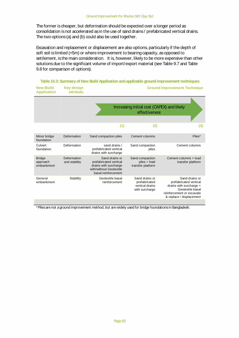
Ground Improvement for Khulna Soft Clay Soil
Page 83
The former is cheaper, but deformation should be expected over a longer period asconsolidation is not accelerated as in the use of sand drains / prefabricated vertical drains.The two options (a) and (b) could also be used together.
Excavation and replacement or displacement are also options, particularly if the depth ofsoft soil is limited (<5m) or where improvement to bearing capacity, as opposed tosettlement, is the main consideration. It is, however, likely to be more expensive than othersolutions due to the significant volume of import/export material (see Table 9.7 and Table9.8 for comparison of options).
Table 10.3: Summary of New Build Application and applicable ground improvement techniquesNew BuildApplication
Key designattribute
Ground Improvement Technique
(1) (2) (3)
Minor bridgefoundation
Deformation Sand compaction piles Cement columns Piles*
Culvertfoundation
Deformation sand drains /prefabricated verticaldrains with surcharge
Sand compactionpiles
Cement columns
Bridgeapproachembankment
Deformationand stability
Sand drains orprefabricated verticaldrains with surcharge
with/without Geotextilebasal reinforcement
Sand compactionpiles + load
transfer platform
Cement columns + loadtransfer platform
Generalembankment
Stability Geotextile basalreinforcement
Sand drains orprefabricated
vertical drainswith surcharge
Sand drains orprefabricated vertical
drains with surcharge +Geotextile basal
reinforcement or excavate& replace / displacement
*Piles are not a ground improvement method, but are widely used for bridge foundations in Bangladesh.
Increasing initial cost (CAPEX) and likelyeffectiveness
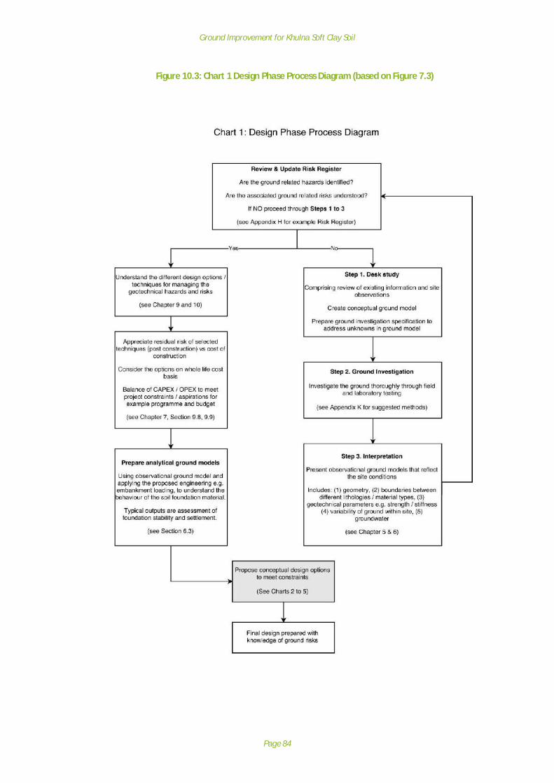
Ground Improvement for Khulna Soft Clay Soil
Page 84
Figure 10.3: Chart 1 Design Phase Process Diagram (based on Figure 7.3)
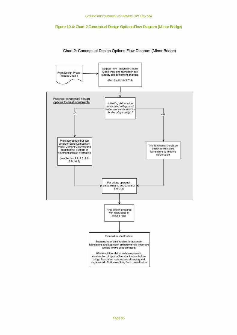
Ground Improvement for Khulna Soft Clay Soil
Page 85
Figure 10.4: Chart 2 Conceptual Design Options Flow Diagram (Minor Bridge)

Ground Improvement for Khulna Soft Clay Soil
Page 86
Figure 10.5: Chart 3 Conceptual Design Options Flow Diagram (Minor Culvert)

Ground Improvement for Khulna Soft Clay Soil
Page 87
Figure 10.6: Chart 4 Conceptual Design Options Flow Diagram (Bridge Approach Embankment)
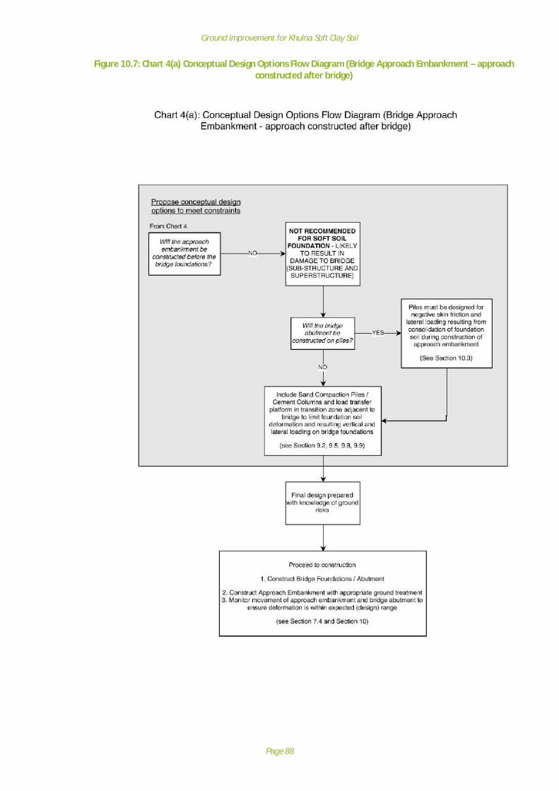
Ground Improvement for Khulna Soft Clay Soil
Page 88
Figure 10.7: Chart 4(a) Conceptual Design Options Flow Diagram (Bridge Approach Embankment – approachconstructed after bridge)

Ground Improvement for Khulna Soft Clay Soil
Page 89
Figure 10.8: Chart 5 Conceptual Design Options Flow Diagram (General Embankment)

Ground Improvement for Khulna Soft Clay Soil
Page 90
11 Further research work
11.1 General
The research project has reviewed existing literature on ground improvement techniques,geological & ground investigation data and site observations of typical rural roads and thedeformation problems faced. Based on the research, appropriate ground improvementtechniques to address typical defects and new build scenarios are presented. Some of thetechniques are widely used in Bangladesh, but others are not. It is also clear that thesuccessful application of the techniques for rural road applications has not been widelytested or documented to demonstrate success or otherwise. Sites where groundimprovement had been used for rural roads were not available or did not exist for thepurposes of the research project.
A critical element for implementation is to demonstrate the techniques in the field underrealistic construction conditions. Proposals for site trials and monitoring of the groundimprovement techniques listed and the fibre mixing options are given.
For all solutions, asset management and ground investigation, a series of suggested researchtopics and improvements are provided that will provide greater confidence in the solutionsprovided and aim to simplify the design process through use of standard details / designsand charts.
11.2 Further research themes
Areas for further research were discussed at the Stakeholder Workshop. A long list of topicsis presented in Table 11.1) and from these, a number have been selected that represent themost valuable research topics that would refine, simplify and facilitate the implementationof ground improvement methods discussed. These selected items are discussed in moredetail in Section 11.3.
Table 11.1: Areas for future development and research – long listArea for further research Description – long list
Asset Management · Links to Policy and Guidance document –frequency / pro-forma
· Condition surveys
· Data Recording / access
· Accessibility of BH logs and testing data
· Training
· Life cycle costing – importance of consideringasset life-cycle in the design stage (fromStakeholder Workshop)
Ground Investigation / validation · Alternatives to BHs / SPT N· Correlation with Panda probes to get Cu / N
profile cheaply· Simple basis for determining OC – leading to
parameters Cc / Su· Database of BH logs and test results for LGED
to access (to avoid need for GI)· Use of piezocone or light Dutch Cone
Penetrometer should be investigated (fromStakeholder Workshop)
· Spatial mapping and statistical evaluation ofdata that can be used as preliminary site data(from Stakeholder Workshop)

Ground Improvement for Khulna Soft Clay Soil
Page 91
Area for further research Description – long list
Applicable to all / many Ground Treatment Methods · Scale test required / fully monitored
· Plant and operatives – applicability to ruralroad locations
· Constructability and quality control
· Retro-fit through existing earthwork asremedial / improvement (up to underside ofexisting earthwork) – not near bridgefoundation….
· Settlement / load profiles for differenttechniques
Sand Compaction Piles · Hammer only / hammer + vibrate
· More sophisticated methods e.g. SAVE-SP
· Impact of depth / spacing / diameter
· Impact of floating piles
· How does variable stratification impactsettlement?
· Use with / without jute LTP (earthwork/bridge)– jute deterioration a problem for long termLTP
· Alternatives to sand – shells, glass? Durabilityduring compaction
Sand Piles / PVD with surcharge · Jute PVD – effectiveness vs synthetic
· Alternatives to sand – shells, glass? Durabilityless of a problem as lighter compaction
Cement Columns · Can admixtures be effectively mixed in situ(mass / columns)
· Cheaper alternatives to cement
· Fabrication of tools· Use for underpinning as remediation of
existing structures
Basal Reinforcement · Use in preventing BC failure in soft groundembankment construction
· Life expectancy of jute
· Use with other techniques
Shallow soil mixing · Use of basic farming e.g. plough and orstandard construction plant
Fibre reinforcement · Plastic bags – shredded and mixed with soils
· Combination of fibres and admixture
· Suitable plant for mixing – see ‘Shallow SoilMixing’
· Jute fibres – Sonthwal and Sahni (2015)
· Could these be used in SCP for greater shearresistance (slope stability)
Re-use of waste products/materials · Tyres / tyre bales for earthwork construction orcreating cellular raft.
· Tyres considered as waste?
· Plastic bags – shredded and mixed with soils
Field application of existing Laboratory basedtesting
· Can admixtures be effectively mixed in situ(mass / columns)
· Can admixtures be effectively mixed ex-situand placed (mass)

Ground Improvement for Khulna Soft Clay Soil
Page 92
11.3 Recommended Further Research Topics (short list)
11.3.1 Field Trials with sand compaction pile and sand drains to demonstrate plantand skills for rural applications
It is appreciated that the sand compaction piling and sand drains are used already on largerscale road and buildings projects, but the use on rural roads is more limited. It is henceimportant to establish whether the skills, plant and quality control aspects of these solutionscan be successfully delivered in accordance with design and specification. A field trial wouldbe the most obvious way of undertaking this validation exercise, using local supply chain.The quality of the installation, particularly for sand compaction piling, is essential inproviding the overall improvement in deformation and strength characteristics that wouldbe needed for a bridge abutment, for example. The structural engineer designing theabutment and bridge superstructure needs to have confidence in the design bearingcapacity and settlement characteristics, or else a piled foundation would need to bespecified.
Field trials could also be used for training and capacity building purposes of the local labourmarket and LGEDs.
11.3.2 Effectiveness of Basal Reinforcement in limiting differential settlement andavoiding BC failure
Basal reinforcement using synthetic polymer geotextiles is widely used internationally tosupport the loads of new embankment infrastructure. The use of geotextiles in Bangladeshis generally restricted to pavement strengthening layers.
The use of jute as an embankment basal reinforcement technique has been recommendedfor implementation in earlier Chapters due to the lower cost and increased use of labourwhen compared to other solutions. However, field results of application are largelyuntested and records of performance of this technique are unavailable in Bangladesh (or notmade available to the research team). So, it would be highly beneficial to implement thetechnique, using international design standards, and closely monitor the site over a numberof years, including pre- and post- consolidation ground investigation works.
11.3.3 Shallow soil mixing with admixtures to improve shear strength of foundationsoil
Shallow soil mixing with standard available plant, or basic modifications to plant can beresearched and trials made. The technique is widely used on its own or in combination with,for example, cement columns. But the addition of alternative admixtures has received someresearch in the laboratory that has proven of benefit to soil properties.
11.3.4 Shallow soil mixing with fibres to improve shear strength of foundation soilThis method has been demonstrated using jute in the laboratory in India, and couldrepresent an economic method to improve foundation soils at relatively shallow depths. It ismore likely to be effective in mass improvement rather than discrete columns, and thelifespan of the fibres also needs to be considered. But initial results show that the soilstrength initially at CBR=3%, can increase to >5% with the addition of jute fibres (1% of dryweight of soil). The mixing of soil with waste e.g. plastic bag strips, or shredded tyres couldalso be looked at.
Ground Improvement for Khulna Soft Clay Soil
Page 93
11.3.5 Spatial mapping and statistical evaluation of dataAs part of the project, a paper titled ‘Statistical Evaluation of Bearing Capacity of Khulna Sub-Soil’ prepared by KUET was reviewed. The work described in the paper was also subject todiscussion at the Stakeholder Workshop.
The paper describes spatial mapping of bearing capacity based on a set of boreholes and testdata and how this can be used for assessing the likely bearing capacity of soils to enableoptioneering to take place. Further soil maps based on information that Government andEducational facilities have collated would be very beneficial for assessing likely hazards, andcould form part of the Ground Model development and Risk Register presented in thereport. Along with geological maps, aerial photos and other sources of information, thesewould be invaluable and cost-effective way of establishing engineering solutions beforeground investigation takes place. Further development and population of the inventory arerecommended.
11.4 Future stage(s) of the project
As stated above, there are many areas where further research would benefit, particularlywith the field application and validation of the techniques outlined in the report. This wasparticularly felt by the attendees at the Stakeholder Workshop – see feedback in AppendixB. Fieldwork and piloting techniques is outside the current or immediate future scope of theProject.
Confidence in the process and effectiveness of the techniques provides the basis forstandard design details and specifications that can be adopted in the future.
The next phase of the project may include the following stages: -
1. Design Guidelines: Production of design guidelines for ground improvementtechniques for rural road construction on soft foundation soils including;
o Provision of typical designs for standard engineering applicationso Provision of standard details that can be used for ground improvement
applicationso Provision of standard specifications that can be used for ground improvement
applicationso Provision of design charts that may be used for simple ground improvement
applicationso Provision of training for scheme designers for application of the new design
guidelines;
2. Construction Guidelines: In order to support future rollout of the groundimprovements solutions for the rural roads network in areas of soft soil foundations,this phase would involve the development of field guidelines for constructionpractitioners including capacity building / training of field engineers and constructionpractitioners for application of the new construction guidelines.
Ground Improvement for Khulna Soft Clay Soil
Page 94
12 Conclusions
There are major concerns for the resilience of rural road embankments exposed to anaggressive coastal environment, in areas of high flood risk and where embankments areoften constructed on soft soil deposits, sometimes with high compressible organic content.This study has collated the relevant findings from existing research, field observations andground investigation to understand the effectiveness and limitations of existing groundimprovement techniques implemented in Khulna region, and has developed appropriaterecommendations to overcome the typical construction challenges for road embankmentsand structures in Khulna region.
The sources of information used to develop the findings of the Final Report are wide andvaried. The principal sources comprise: -
· Stakeholder meetings;· Publications and academic research on the geology of the Khulna Region;· Publications relating to different types of ground treatment methods available
worldwide and those that have been used in Khulna Region;· Observational visits to earthworks and structures to determine indicators of
deformation mechanism;· Intrusive investigation data and laboratory testing (existing information from
literature and new data from selected sites) to characterise the ground;· Publications and academic research on new ground treatment methods that could
be developed into field techniques.
Using the detailed investigation and analysis of the results, observational ground modelshave been developed for to help better understand the deformation mechanisms and assessthe likely contributory causes. The key defects categories identified were as follows: -
· Embankment Defects· Structure Defects (related to ground conditions);· Pavement Defects observed.
The probable cause/mechanisms leading to the defects have been categorised: -1) Deformation
a) Differential settlement
b) Total settlement
2) Stability
a) Bearing capacity
b) Lack of lateral support (provided by foundation soil)
3) Floodwater (erosive action, pore-pressure increase)
4) Adjacent land use
5) Shrink/swell cycle (of soils)
6) Embankment construction (quality, materials)
7) Vehicle overloading
Ground improvement techniques have been presented that are considered either (a)technically feasible and (b) within the likely budget for rural road construction together withguidance for implementation to deal with specific construction issues. From the literature

Ground Improvement for Khulna Soft Clay Soil
Page 95
review, and discussions with local stakeholders, the techniques are mostly in use inBangladesh, although not necessarily for the rural road application. The groundimprovement techniques considered within the report are: -
· Excavate and Replace / Displacement· Sand Compaction Pile· Sand Drain (with surcharge)· Prefabricated Vertical Drains (with surcharge)· Geotextile basal reinforcement· Cement Columns
Topics for further research are presented that will improve the ability to apply groundimprovement techniques in Khulna Region. The recommended further research includes:
· Field Trials with sand compaction pile and sand drains to demonstrate plant andskills for rural applications
· Effectiveness of Basal Reinforcement in limiting differential settlement and avoidingBC failure
· Shallow soil mixing with admixtures to improve shear strength of foundation soil· Shallow soil mixing with fibres to improve shear strength of foundation soil· Spatial mapping and statistical evaluation of data
The next stages of the project may include the following: -
1. Design Guidelines: Production of design guidelines for ground improvementtechniques for rural road construction on soft foundation soils.
2. Construction Guidelines: In order to support future rollout of the groundimprovements solutions for the rural roads network in areas of soft soil foundations,this phase would involve the development of field guidelines for constructionpractitioners including capacity building / training of field engineers and constructionpractitioners for application of the new construction guidelines.

Ground Improvement for Khulna Soft Clay Soil
Page 96
ReferencesAdhikari, D. K., Roy, M. K., Datta, D. K., Roy, P J, Roy, D. K., Malik A. R. and Badrul Alam, A. K.
M. (2006). Urban Geology: A Case of Khulna City Corporation, Bangladesh. J. LifeEarth Sci.
Ahsan, K., Hossain, I., Shaikh, M. and Alamgir, M. (2014). Soft soil improvement by cementcolumn. International Journal of Advanced Structures and Geotechnical Engineering
Alamgir, M. and Chowdhury, K. H. (2004). Ground Improvement Methods Recently Practicedto Solve the Geotechnical Engineering Problems in Bangladesh. InternationalConference on Case Histories in Geotechnical Engineering
Arifuzzaman and Hasan, A (2013). Evaluation of Foundation Difficulties over Soft OrganicSoil. University of Information Technology and Sciences, Dhaka, Bangladesh
Asma, U.H., Rafizul, I.M., Hasibul, M.H., Roy, S., Didarul, M. and Shohel, M.R. (2013).Engineering Behaviour of Cement Stabilized Soil: New Statistical Model. KhulnaUniversity of Engineering & Technology
Banik, R., Khatun, N., Shaikh, M and Molla, K. A. (2014). Statistical Evaluation of bearingcapacity of Khulna Sub-Soil. International Journal of Advanced Structures andGeotechnical Engineering
Bhagwan J, Yadav O.P & Sharma N. K (unknown). Jute geotextile for road applications – fieldtrials by CRRI.
Bowles, J. (1997). Foundation Analysis and Design International Edition. McGraw Hill
British Standards Institution (2005). BS 8002: Code of practice for earth retaining structures.British Standards Institution.
British Standards Institution (2010). BS 8006-1: Code of practice for strengthened/reinforcedsoils and other fills. British Standards Institution
Burland, J.B. et al (1979). Movements around excavations in London Clay. Proc. 7thEuropean Conf. SMFE. Vol.1. Proc. 7th European Conf. SMFE. Vol.1.
CIRIA (1996). CIRIA Special Publication SP123 Soil Reinforcement with Geotextiles. CIRIA
CIRIA (2002). CIRIA Publication C573. A guide to ground treatment. CIRIA
Craig, R. (2004). Soil Mechanics 7th Edition. Spon Press
Dhar, A. S., Siddique, A. and Ameen, S. F. (2011). Ground Improvement using Pre-loadingwith Prefabricated Vertical Drains. International Journal of Geoengineering CaseHistories
GeoGuides (2002). GeoGuide 1: Road Embankments on Soft Soils: Occurrence & GeneralNature of Soft Soils. Ministry of Settlement and Regional Infrastructure
GeoGuides (2002). GeoGuide 2: Road Embankments on Soft Soils: Site Investigation of SoftSoils: Design & Fieldwork. Ministry of Settlement and Regional Infrastructure
GeoGuides (2002). GeoGuide 3: Road Embankments on Soft Soils: Site Investigation of SoftSoils: Laboratory Testing. Ministry of Settlement and Regional Infrastructure
GeoGuides (2002). GeoGuide 4: Road Embankments on Soft Soils: Design and ConstructionMethods. Ministry of Settlement and Regional Infrastructure
Hansbo, S., (1960). Consolidation of clay with special reference to influence of vertical sanddrains. Swedish Geotechnical Institute, Stockholm, Proceedings No. 18, 160 p.

Ground Improvement for Khulna Soft Clay Soil
Page 97
Hansbo, S., (1979). Consolidation of clay by band-shaped prefabricated drains. GroundEngineering, London, 12(5) 16-25.
Harada, K., Ohbayashi, J., Matsumoto, J., Kubo, Y. and Akima, T. (2015). New groundimprovement technologies under restricted conditions in Japan. The 15th AsianRegional Conference on Soil Mechanics and Geotechnical Engineering
Khan, A. J., (2009). Performance of a prefabricated vertical jute drain in a remoulded softsoil. Proc. of Bangladesh Geotechnical Conference (2009)
Khan, A. J., Huq, F. and Hossain, S. Z. (2014). Application of Jute Geotextiles for Rural RoadPavement Construction. Ground Improvement and Geosynthetics GSP 238 ASCE2014
Kirsch K and Bell A (2013). Ground Improvement 3rd Edition. Spon Press
Kitazume M (2005). The Sand Compaction Pile Method. A A Balkema Publishers
Liang, R. Y. (2011). Innovative soft clay improvement technique using vacuum and dynamiccompaction (HVDM). 2011 Pan-Am CGS Geotechnical Conference
Local Government Engineering Department (1999). Road Pavement Design Manual
Local Government Engineering Department and Japan International Cooperation Agency(2005), Road Design Standards, Standard Designs and Costings for Zila, Upazila andUnion Roads, Bridges and Culverts
Local Government Engineering Department (2004). Technical Specification for Bridges on theUpazila and Union Roads.
Local Government Engineering Department (1999). Standard Specifications for Feeder RoadType-B & Rural Road Type-R1 under LGED.
Mahamud, M. A., Alamgir, M. and Hossain, M. J. (2008). Laboratory Investigation on theBehaviour of Improved Organic Soil of Khulna Region. International Conference onCase Histories in Geotechnical Engineering
McGown, A and Jarrett, P M (1997). Indonesian Geotechnical Materials and ConstructionGuides Stage 1, Seminar 1, The Origins, Nature and Characterization of Soft Soils,Organic Soils and Peat. Institute of Road Engineering Agency for Research andDevelopment Ministry of Public Works, Indonesia
McGown, A and Jarrett, P M (1997). Seminar 2, Tropical Soft Soils and Peats. Institute ofRoad Engineering Agency for Research and Development Ministry of Public Works,Indonesia
Mitchell, J. M and Jardine, F. M. (2002). A Guide to Ground Treatment. CIRIA
Moh, Z. C, Ruenkrairergsa, T., Lin, P. C. and Karim, M. (1998). Improvement of Soft BangkokClay by Use of Prefabricated Vertical Drain. Proceedings of 13th Southeast AsianGeotechnical Conference
Mollah, M A (1993). Geotechnical conditions of the deltaic alluvial plains of Bangladesh andassociated problems. Government Centre for Testing and Research, Ministry ofPublic Works
Patel, N. A. and Mishra, C. B. (2014). Improvement the Strength of Inorganic Clayey Soilusing Cement Additive. International Journal of Current Engineering and Technology
Patel, N. A., Mishra, C. B., Dave, S. K. and Parmar, D. K (2015). Investigating the Modificationsin Properties of Clayey Soil Utilizing ppc for Variable Dynamic Compaction.International Journal of Research in Engineering and Technology

Ground Improvement for Khulna Soft Clay Soil
Page 98
Planning Commission (2004), Road Design Standards, Standard Designs and Costings for Zila,Upazila and Union Roads, Bridges and Culverts (2004)
Rabbee, T. and Rafizul, I. M. (2012). Strength and Compressibility Characteristics ofReconstituted Organic Soil at Khulna Region of Bangladesh. International Journal ofEngineering and Technology
Rafizul, I. M., Assaduzzaman and Alamgir, M. (2012). The effect of chemical admixtures onthe geotechnical parameters of organic soil: a new statistical model. Int. Journal ofApplied Sciences and Engineering Research
Reshad Md, Ali, E., Karim, M F and Rahman, Z. (2004). Engineering Geology of KhulnaMetropolitan City Area. Bangladesh Journal of Geology
Sarkar, G., Islam, R., Alamgir, M. and Rokonuzzaman (2012). Study on the GeotechnicalProperties of Cement based Composite Fine-grained Soil. International Journal ofAdvanced Structures and Geotechnical Engineering
Sarkar, G., Islam, R., Alamgir, M., Rokonuzzaman, Dr (2012). Interpretation of Rice Husk Ashon Geotechnical Properties of Cohesive Soil. Global Journal of researches inengineering Civil and Structural engineering
Sarkar, G., Siddiqua, S., Banik, R., and Rokonuzzaman (2015). Prediction of soil type andstandard penetration test (SPT) value in Khulna City, Bangladesh using generalregression neural network. Quarterly Journal of Engineering Geology andHydrogeology
Seah, T. H. (2005). Design and construction of ground improvement works at SuvarnabhumiAirport. -
Sebayang, I R (1998). Road Construction Over Tropical Peats and Organic Soils in Indonesia.University of Strathclyde
Serajuddin, M (1998). Some Geotechnical Studies on Bangladesh Soils: A Summary of Papersbetween 1957-96. Journal of Civil Engineering, The Institution of Engineering,Bangladesh
Situmorang, R (1998). Construction of Roads Over Indonesian Tropical Inorganic Soft Soils.University of Strathclyde
Tomlinson, M J (1995). Foundation Design & Construction – 6th Edition. Longman
Unknown (1998). Indonesian Geotechnical Materials Construction Guide Project. Institute ofRoad Engineering Agency for Research and Development Ministry of Public Works,Indonesia
Unknown (2007). A firm winner - Lime Cement Powder Mix for new road. GroundEngineering
U.S. Army Corps of Engineers (1990), Engineering Manual 1110-1-1904 Settlement Analysis.
Vidmar, S., Gaberg, A. and Kardelj, E. (unknown). Successful Highway Construction on VerySoft Soils.

Ground Improvement for Khulna Soft Clay Soil
Page 99
Appendix A: Stakeholder meetings
Meeting Key Attendees NotesStart-up meeting(09-08-16)
Md. Abul Bashar (LGED superintendingengineer)Md. Shahidul Haque (LGEDsuperintending engineer)Md. Abul Kalam Azad (LGED AdditionalChief Engineer (Implementation)Les Sampson (ReCAP/Cardno)Chandra Shrestha (ReCAP / Cardno)
Ian Duncan presented the project proposal to theassembled LGED members
Blue Gold Program(10-08-16)
Mofazzal Ahmed (Deputy ComponentLeader)
Useful notes gained on construction methods andconstraints, maintenance and typical groundimprovement methods that are implemented
Follow-up meetingwith LGED +laboratory visit(11-08-16)
Md. Abul Bashar (LGED superintendingengineer) + LGED design team
Discussed various issues: -Current practice for embankment construction andremediationTypical form of contractGround investigation capabilityConstruction plant and staffingAvailability of data sources such as GIS, geologicalmaps
Follow-up meetingwith LGED(18-08-16)
Tapas Chowdhury, Senior AssistantEngineer, Design Unit + LGED DesignTeam
Discussed various issues: -Current practice for asset managementLGED experience in soft ground + designmethodologyLGED owned plant and GI equipmentSites for initial assessment
Technical Meeting(07-11-16)
Md. Abul Bashar (LGED superintendingengineer) + LGED design team
Presentation of Inception Report.
Technical Meeting(07-02-17)
Md. Abul Bashar (LGED superintendingengineer) + LGED design team
Presentation of Field and Laboratory Testing results
Technical Meeting(11-07-17)
Md. Abul Bashar (LGED superintendingengineer) + LGED design team
Review of Draft Final Report and recommendationsfor inclusion in Final Report.
StakeholderWorkshop(20-09-17)
See Appendix B Delivery of Draft Final Report findings.See Appendix B

Ground Improvement for Khulna Soft Clay Soil
Page 100
Appendix B: Stakeholder workshop questions and responses
The purpose of the workshop was to demonstrate the progress of the project against the abovestated aims; provide technical training and capacity building through the content of the projectpresentation and response to technical questions; and obtain feedback for the ongoingdevelopment, uptake, and embedment of the project findings and recommendations. The technicalfeedback and recommendations from the workshop have been incorporated into the Final Reportand subsequent phases of the project, for which this Stakeholder Report acts as a supportingdocument.
Agenda09:30 – 10:00 Walk-in and registration (MM)
10:00 – 10:40
Inaugural Session to be chaired by Mr. Md. Abdul Kalam Azad, Additional Chief Engineer(Implementation) and Chairperson, ReCAP-ASCAP Steering Committee
· Welcome address by Mr. Abdul Bashar, Superintending Engineer, LGED;
· Speech by Jasper Cook, Team Leader, ReCAP;
· Speech Mr. Md. Abdul Kalam Azad, Additional Chief Engineer, LGED;
· Speech and Inauguration of working session, Mr. Shyama Prosad Adhikari, Chief Engineer,LGED.
10:40 – 11:00 Tea Break
11:00 – 13:00 Working Session to be chaired by Mr. Md. Khalilur Rahman
11:00 – 11:20Presentation on “Overview of Current Ground Improvement methods used internationally & in KhulnaRegion (MM)
11:20 – 11:40 Presentation on “Field Survey for Sites in Khulna Region” (MM)
11:40 – 12:30 Laboratory Testing & Ground Models from Sites in Khulna Region (MM)
12:30 – 13:00 Open Discussion
13:00 – 13:30 Summary Session, to be chaired by Md. Abdul Kalam Azad, Additional Chief Engineer (Implementation)
AttendeesThe list of those who attended the event are included in Table 12.1 below:
Table 12.1: List of Attendees from Workshop
# Name Organisation & Designation
1 Md. Abul Kalam Azad Local Government Engineering Department, Additional ChiefEngineer(Implementation)
2 Md. Mohsin Local Government Engineering Department, Additional Chief Engineer,Integrated Water Resources Management (IWRM)
3 Md Joynal Abedin Local Government Engineering Department, Additional Chief Engineer(Maintenance)
4 Mohammad Anwar Hossain Local Government Engineering Department, Additional Chief Engineer (UrbanManagement)

Ground Improvement for Khulna Soft Clay Soil
Page 101
# Name Organisation & Designation
5 Md. Khalilur Rahman Local Government Engineering Department, Additional Chief Engineer
6 Iftekhar Ahmed Local Government Engineering Department, Additional Chief Engineer
7 Jasper Cook Chief Scientific Advisor, Research for Community Access Partnership(ReCAP/AsCAP)
8 Les Sampson Team Leader, Research for Community Access Partnership (ReCAP/AsCAP)
9 Maysam Abedin Regional Technical Manager, Asia, Research for Community Access Partnership(ReCAP/AsCAP)
10 AKM Sahadat Hossain Local Government Engineering Department, Senior Engineer, Integrated WaterResources Management (IWRM)
11 Khondakar Ali Noor Local Government Engineering Department, Senior Engineer (Design)
12 Md. Abul Bashar Local Government Engineering Department, Senior Engineer, Integrated WaterResources Management (IWRM)
13 Abdur Rashid Khan Local Government Engineering Department, Senior Engineer (Training)
14 Md. Mosleh Uddin Local Government Engineering Department, Senior Engineer (Admin)
15 Md Abu Md Shahriar Local Government Engineering Department, Project Director, Greater FaridpurRural Infrastructure Development Project (GFRIDP)
16 Bipul Chandra Banik Local Government Engineering Department, Project Director (UDIP, KBS)
17 Md. Kamrul Ahsan Local Government Engineering Department, Project Director, Barisal DivisionRural Infrastructure Development Project (BDRIDP)
18 Md. Jashim Uddin Local Government Engineering Department, Project Director, BangladeshAgricultural Infrastructure Development Program (BAIDP)
19 Md. AKM Lutfur Rahman Local Government Engineering Department, Project Director, Coastal ClimateResilient Infrastructure Project (CCRIP)
20 Gopal Chandra Debnath Local Government Engineering Department, Project Director, HaorInfrastructure and Livelihood Improvement Programme (HILIP)
21 Gopal Krisna Debnath Local Government Engineering Department, Project Director, Small ScaleWater Resources Developmemt Project (SSWRDP)
22 Sachin Chandra Halder Local Government Engineering Department, Project Director (Patuakhali-Barguna)
23 Mahbub Imam Morshed Local Government Engineering Department, Assistant Chief Engineer
24 Md. Nazrul Islam Local Government Engineering Department, Deputy Project Director (LargeBridges Construction)
25 Md. Zahidur Rahman Local Government Engineering Department, Executive Engineer (Design)
26 Md. Azherul Islam Local Government Engineering Department, Executive Engineer (Design)
27 Md. Abadat Ali Local Government Engineering Department, Executive Engineer (Design)
28 Md. JM Azad Hossain Local Government Engineering Department, Executive Engineer, Third PrimaryEducation Development Programme (PEDP III)
29 Md. Tarikuzzaman Local Government Engineering Department, Executive Engineer (QualityControl)
30 Md. Abdur Rahim Local Government Engineering Department, Executive Engineer (QualityControl)
31 Syed Abdur Rahim Local Government Engineering Department, Executive Engineer (Maintenance)
32 Abdul Monzur Md. Sadeque Local Government Engineering Department, Executive Engineer (Planning)

Ground Improvement for Khulna Soft Clay Soil
Page 102
# Name Organisation & Designation
33 Mahbub Alam Local Government Engineering Department, Executive Engineer, Third PrimaryEducation Development Programme (PEDP III)
34 Md. Maksalim Local Government Engineering Department, Executive Engineer, Third PrimaryEducation Development Programme (PEDP III)
35 Ripon Hore Local Government Engineering Department, Assistant Engineer, Research &Development
36 Partha Kumar Sarker Local Government Engineering Department, Assistant Engineer, QualityControl
37 Manas Mondal Local Government Engineering Department, Assistant Engineer, ChiefEngineer's Office
38 Sheikh Anisur Rahman Deputy Project Director (Emergency Cyclone Recovery and Restoration Project,Local Government Engineering Department)
39 Md. Khorshed Alam Local Government Engineering Department
40 Md. Enamil Hoque Khan Local Government Engineering Department, Sr. Assistant Engineer, QualityControl
41 Md. Anwarul Islam Local Government Engineering Department
42 Khan Md Rabiul Alam Local Government Engineering Department, Media Consultant, Second RuralTransport Improvement Project (RTIP-II)
43 AKM Mostofa Morshed Local Government Engineering Department
44 Md. Zakir Hossain Local Government Engineering Department
45 Dr. Mehedi Ahmed Ansary Bangladesh University of Engineering and Technology
46 Dr Abdullah Al Mamun Roads and Highways Department, Director, Road Research Laboratory
47 Dr Jiban Kumar Sarker Bangladesh Water Development Board, Executive Engineer (Design)
48 Salma Akter Roads & Highways Department, Executive Engineer, Road Research Laboratory
49 Engr. Jiban Krishna Saha Second Rural Transport Improvement Project (RTIP-II), Quality AssuranceSpecialist (Field Level Official)
50 Mostadar Rahman Senior Consultant, Design
51 Ahmed Nawaz Municipal Government and Services Project (MGSP), Deputy Team Leader
52 Ahsan Habib Euroconsult Mott MacDonald, Sustainable Rural Infrastructure ImprovementProgramme, Deputy Team Leader
53 Mohammad Imran Euroconsult Mott MacDonald, Design & Construction Engineer
54 MD Shamsul Islam Euroconsult Mott MacDonald, Khulna Clay Project, Deputy Team Leader
55 Gazi A Rahmani Euroconsult Mott MacDonald, Senior Business Development Advisor
56 Abu Fattah Local Government Engineering Department, Media Consultant
57 Ian Duncan Euroconsult Mott MacDonald, Khulna Clay Project, Team Leader
58 Richard Lebon Euroconsult Mott MacDonald, Khulna Clay Project, Project Manager
59 Abdullah Al Baky Euroconsult Mott MacDonald, Khulna Clay Project, Research Associate

Ground Improvement for Khulna Soft Clay Soil
Page 103
Example Design Scenario presented at Workshop on 20-09-17
Example Design Scenario –new approach embankment
Ian Duncan

Scenario: -Rural road
New river crossing
Selected engineering – single spanbridge with abutments and earthworkapproach ramps
20m + soft ground
4m high embankments
03/10/2017 Mott MacDonald | Presentation 63
New-buildApproach embankment
• Consider the ground relatedhazards & associated risks
• Undertake initial studies andinvestigations
• Develop the ground model
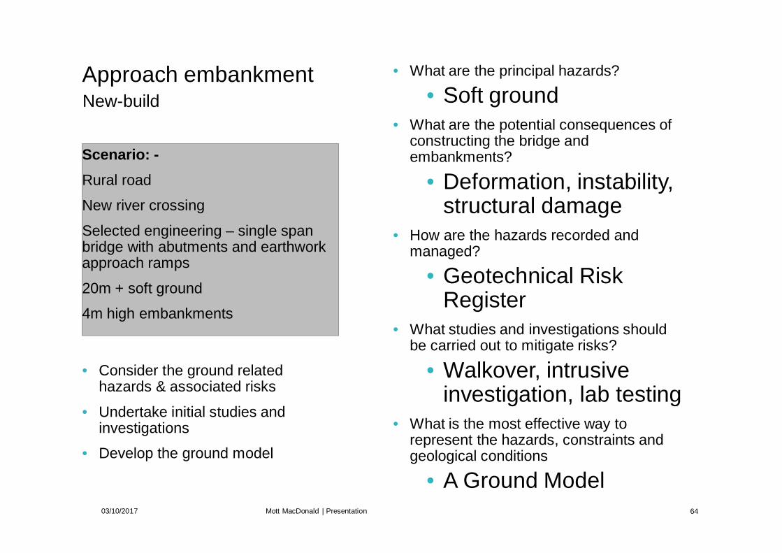
Scenario: -Rural road
New river crossing
Selected engineering – single spanbridge with abutments and earthworkapproach ramps
20m + soft ground
4m high embankments
03/10/2017 Mott MacDonald | Presentation 64
New-buildApproach embankment • What are the principal hazards?
• Soft ground• What are the potential consequences of
constructing the bridge andembankments?
• Deformation, instability,structural damage
• How are the hazards recorded andmanaged?
• Geotechnical RiskRegister
• What studies and investigations shouldbe carried out to mitigate risks?
• Walkover, intrusiveinvestigation, lab testing
• What is the most effective way torepresent the hazards, constraints andgeological conditions
• A Ground Model
• Consider the ground relatedhazards & associated risks
• Undertake initial studies andinvestigations
• Develop the ground model

Risk Register

Ground Model
* Drawing not toscale
River
AbutmentNew Approach Embankment
Soft Compressible Ground

Ground Model – load from earthworks andabutment
* Drawing not toscale
River
AbutmentNew Approach Embankment
Soft Compressible Ground

Ground Model – ground response to load –settlement, failure
* Drawing not toscale
River
AbutmentNew Approach Embankment
Soft Compressible Ground
Settlement resultingfrom load
No support toabutment –deformation /failure
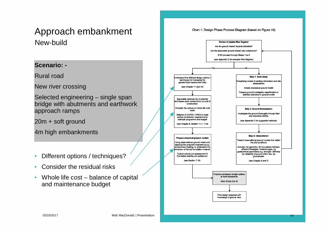
Scenario: -Rural road
New river crossing
Selected engineering – single spanbridge with abutments and earthworkapproach ramps
20m + soft ground
4m high embankments
03/10/2017 Mott MacDonald | Presentation 69
New-buildApproach embankment
• Different options / techniques?
• Consider the residual risks
• Whole life cost – balance of capitaland maintenance budget

Scenario: -Rural road
New river crossing
Selected engineering – single spanbridge with abutments and earthworkapproach ramps
20m + soft ground
4m high embankments
03/10/2017 Mott MacDonald | Presentation 70
New-buildApproach embankment
• Different options / techniques?
• Consider the residual risks
• Whole life cost – balance of capitaland maintenance budget
• What are the likely design options?
• Piles for abutment• Earthworks –
surcharge, drains,geotextile
• What constraints are applicable to themethods?
• Programme• Complexity / skills• Cost• Materials, plant
• What are the residual risks of thesemethods?
• Long term movement• Damage to piles• Differential movement

Scenario: -Rural road
New river crossing
Selected engineering – single spanbridge with abutments and earthworkapproach ramps
20m + soft ground
4m high embankments
03/10/2017 Mott MacDonald | Presentation 71
New-buildApproach embankment
• Prepare analytical model based onthe investigation and proposedengineering
• What are the inputs for analytical model?
• Engineering Geometry /loadings
• Geological boundaries• Geotechnical properties
of foundation soil –which?
• What are the key outputs of the analyticalmodel?
• Limit states (ultimate /serviceability)
• Amount of deformation• Rate of deformation• Stable / unstable

Scenario: -Rural road
New river crossing
Selected engineering – single spanbridge with abutments and earthworkapproach ramps
20m + soft ground
4m high embankments
03/10/2017 Mott MacDonald | Presentation 72
New-build – Build Embankment FirstApproach embankment
• Select the appropriate Chart andwork through the decision makingprocess
• Embankment constructed before /after bridge (Chart 4 / Chart 4(a))

Build embankment first – stagedconstruction with basal geogrid (+surcharge); support abutment with piles
* Drawing not toscale
River
Soft Compressible Ground
Staged construction if soilassessed to fail underembankment load
Basal geogrid

Build embankment first – stagedconstruction with basal geogrid (+surcharge); support abutment with piles
* Drawing not toscale
River
Staged construction
Staged construction if soilassessed to fail underembankment load
Improved Strength Ground
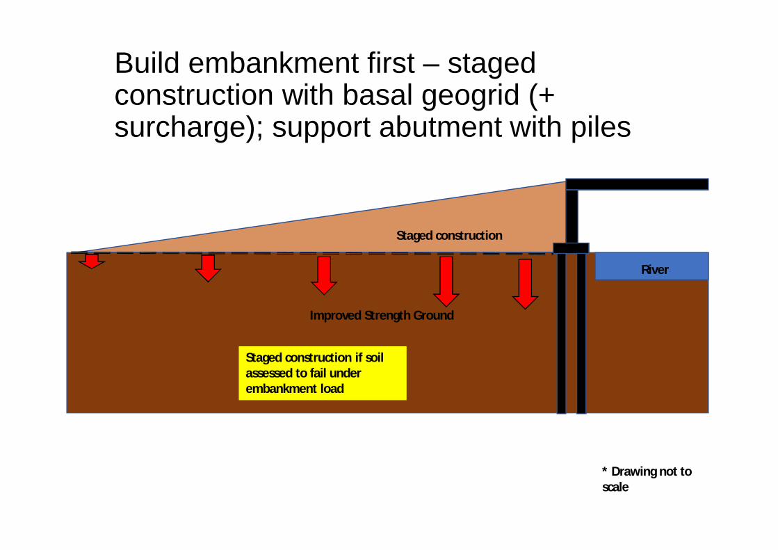
Build embankment first – stagedconstruction with basal geogrid (+surcharge); support abutment with piles
* Drawing not toscale
River
Staged construction
Staged construction if soilassessed to fail underembankment load
Improved Strength Ground

Build embankment first – with vertical drains(+ surcharge); support abutment with piles
* Drawing not toscale
River
New Approach Embankment
Soft Compressible Ground
Improve ground strength – PVD orSD before embankment constructed

Build embankment first – with vertical drains(+ surcharge); support abutment with piles
* Drawing not toscale
River
Staged construction ?
Soft Compressible Ground
Staged construction if soilassessed to fail underembankment load

Build embankment first – with vertical drains(+ surcharge); support abutment with piles
* Drawing not toscale
River
Basal geogrid allows higher embankment tobe built before failure – surcharge can alsobe applied to speed consolidation
Basal geogrid?
Improved Strength Ground

Build embankment first – with vertical drains(+ surcharge); support abutment with piles
* Drawing not toscale
River
Piles
AbutmentNew Approach Embankment
Improved Strength Ground
Construct piles, abutment and bridge after consolidation period
Basal geogrid?
Reduce (not eliminate) settlement, vertical andhorizontal loads on piles

Scenario: -Rural road
New river crossing
Selected engineering – single spanbridge with abutments and earthworkapproach ramps
20m + soft ground
4m high embankments
03/10/2017 Mott MacDonald | Presentation 80
New-build – build bridge firstApproach embankment
• Select the appropriate Chart andwork through the decision makingprocess
• Embankment constructed before /after bridge (Chart 4 / Chart 4(a))

Bridge built first – support abutment withpiles
* Drawing not toscale
River
Piles
AbutmentNew Approach Embankment
Soft Compressible Ground

Bridge built first – support abutment withpiles – can result in serious damage
* Drawing not toscale
River
Piles
AbutmentNew Approach Embankment
Soft Compressible Ground
Settlement resultingfrom load
Step at interface
Additional vertical load onpiles due to settlement

Bridge built first – support abutment withpiles – can result in serious damage
* Drawing not toscale
River
AbutmentNew Approach Embankment
Soft Compressible Ground
Settlement resultingfrom load
Additional horizontal loadon piles due to squeezing
Abutment moves withpiles, bearings lock,deck locks
Potentiallystructuraldamage to piles /connection
Piles

Build bridge first – support abutment withpiles + support embankment with SCP or CC
* Drawing not toscale
River
Piles
AbutmentNew Approach Embankment
Soft Compressible Ground
Improve ground strength – SCP orCC, before embankment constructed– further away from abutment, canuse PVD, SC
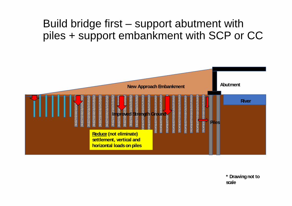
Build bridge first – support abutment withpiles + support embankment with SCP or CC
* Drawing not toscale
River
Piles
AbutmentNew Approach Embankment
Reduce (not eliminate)settlement, vertical andhorizontal loads on piles
Improved Strength Ground

Ground Improvement for Khulna Soft Clay Soil
Page 104
PhotosA selection of photos from the Stakeholder workshop are shown below.

Ground Improvement for Khulna Soft Clay Soil
Page 105
FeedbackThe key issues and comments arising in the open floor discussion are summarised below. Ininaugurating the working session, Mr. Shyama Prosad Adhikari, Chief Engineer, LGED, highlighted theeffects of climate change and flood damage on many kilometres of rural roads, and requestedcontinued support in developing cost-effective technical solutions. Highlighting the role of LGED’srural roads research fund, Mr. Adhikari emphasised the importance of bridging the gap betweenresearch and field-level implementation, and of applied research, where infrastructure investmentsare more cost-effective if research is applied.
For each comment or topic arising during this working session, a summary of the response providedeither during the floor discussion or by inclusion and/or recommendations in the Final report isprovided below. Comments from the floor are provided in plain text, and responses from theauthors of this report are shown in italics.
· The limitation on comprehensive consolidation testing in rural road budgets.The consolidation characteristics of the clays / silts / organic material can vary quite considerablybased on the nature of the sample tested. The consolidation of the soil below an embankment loadaffects quite considerable depths, certainly 1-2 times the embankment width and hence covers alarge amount of soil. The consolidation test is undertaken on a very small sample that is difficult toextract in an intact state from the ground, even in ideal soil and with high quality plant andexperienced operatives. In very soft soil, it is very difficult to obtain (a) a high-quality sample, and (b)transfer the sample to a laboratory without changing the in-situ state. Sufficient number of sampleswould also need to be undertaken to give a representative number of consolidation test results, suchthat a statistical approach can be used. The associated budgets are anticipated to be beyond therural road budget. If only a few tests could be undertaken on samples of dubious quality, it would bemore prudent to use conservative ‘book’ values.
· The availability of potentially useful soil maps.As part of our review, we identified ‘Statistical Evaluation of Bearing Capacity of Khulna Sub-Soil’prepared by KUET. This provide spatial mapping of bearing capacity based on a set of boreholes andtest data. This is a good starting place for assessing the likely bearing capacity soils to enableoptioneering to take place. Further soil maps based on information that Government and Educationalfacilities have collated would be very beneficial for assessing likely hazards, and would form part ofthe Ground Model development and Risk Register presented in the report. Along with Geologicalmaps, aerial photos and other sources of information, these would be invaluable and cost-effectiveway of establishing engineering solutions before ground investigation takes place.
· The potential cooperation with the Roads & Highways Department in future work.This is something that the authors of the report would fully support, dependent on the strategyadopted by ReCAP/LGED following the conclusion of the Final Report and adoptions of therecommendations from this project.
· Use of piezocones.The use of cone penetrometer testing (CPT) or Dutch Cone is very valuable for the rapid assessmentof soft foundation soils. CPT is very widely employed in soft ground for profiling and determininggeotechnical characteristics and should be used in conjunction with boreholes to calibrate the CPTcone and sleeve resistance measurements. The piezocone variant permits measurement of porewater pressure in the soil and dissipation testing to assess the hydraulic conductivity for use inconsolidation assessment. Plant is available in Bangladesh as noted in Appendix C of the Final Report,but is likely to have limited availability, and hence be more costly than other methods. Increased useof the method would bring the cost down.

Ground Improvement for Khulna Soft Clay Soil
Page 106
· Implications of whole life costing for rural road embankments on soft soil.It was considered from the floor that the solutions recommended under this project would provemore costly than current techniques. However, the responses from around the floor emphasisedthe importance of considering asset life cycle cost in the design process – i.e. where a greaterinvestment up front would result in longer-lasting infrastructure and reduced costs in maintenanceand reconstruction. As outlined in Chapter 7 of the Final Report, whole life-cycle approach isfundamental to the project aims. The consideration of whole life costing is included in the flowcharts provided for the decision-making process in designing solutions for embankments on soft soil.
· In the final stages, the floor discussion focussed on the collective identification of the wayforward
for application and uptake of the report. These discussions are summarised in the conclusions of thefinal report (see chapter 12).
In addition to the discourse outlined above, a comments sheet was distributed to all participants,focussing on four key questions surrounding the project aims, objectives and presented results. Thequestions, comments and responses to these comments are copied below:
Question 1
Which of the groundimprovement techniques doyou regard as most suitable forapplication to rural roads andwhy?
Comments
Submitted comments are shown in plain text, authors’ responsesin italics where required.
Summary of 17 No. responses received for Question 1.
The attendees agreed that the methods recommended weresuitable, but needed to be considered on a site by site basis and ondepended on the importance of the road / structure. The familiarSand Drain is a popular choice with many, as is the SandCompaction Pile. The use of basal geogrids in combination withSand Drains or prefabricated vertical drains (PVD) / surcharge isalso considered suitable as an economic and simple method.
Excavate and replace is mentioned by one attendee, and the useof grouting is suggested in addition to the methods recommendedin the report. We consider that grouting is not suitable for ruralroad applications.
Soil stabilisation with cement and sand is noted by one attendeeand we consider this an area for future research as detailed inChapter 11 of the Final Report.
Cement columns are not a popular choice, based on cost. This alsomay be due to knowledge of technique, availability of plant andskills to operate.

Ground Improvement for Khulna Soft Clay Soil
Page 107
Question 1
Which of the groundimprovement techniques doyou regard as most suitable forapplication to rural roads andwhy?
Comments
Submitted comments are shown in plain text, authors’ responsesin italics where required.
Individual Responses received for Question 1:
Basal Reinforcement with surcharge because suitable forconstruction due to simple and cost effective.
Geo-Textile basal reinforcement and PVD with surcharge are themost suitable methods for ground improvement techniques.Comparatively they are easy to implement and provide moresustainable benefit etc.
Sand drain with surcharge. (sand pile/PVD).
Sand compaction for increasing soil density.
Removal of soft soil and pouring dense soil.
Sand compaction pile, easy to construct, cost effective.
I think Geotextile/ Geogrid should be a economic and suitablesolution for ground improvement.
Other solution like sand drains, cement column are costly as wellas time consuming.
Basal reinforcement can be used in rural road because it is notexpensive.
Sand-drain, basal reinforcement and surcharge.
Sand compaction pile
Geo-Textile raft
This is assumed to relate to basal geogrid, covered in the FinalReport
Soil stabilisation with cement, sand and clay
Vertical sand drain (sand column) placing is most suitable.Instruments are available, easy to implement and very suitable forquick settlement.

Ground Improvement for Khulna Soft Clay Soil
Page 108
Question 1
Which of the groundimprovement techniques doyou regard as most suitable forapplication to rural roads andwhy?
Comments
Submitted comments are shown in plain text, authors’ responsesin italics where required.
It will depend on the importance of the road. If it is in higheconomic zone, cement column can be provided. Otherwise sanddrain is a widely used method.
Improvement by geo-grouting because it is easier to implementand may be cost effective.Jet grouting is not suitable for the engineering application on ruralroads. Jet grouting is very specialised, expensive and requires highlevels of skill and site controls to avoid blow-out at surface due tothe very high pressures used with this technique.Also improve the bearing capacity of sand piling, it is also low costand easier technique.
Question 2
Are there any additionalconstraints to the use of theseground improvementtechniques that you considershould be incorporated?
Comments
Submitted comments are shown in plain text, authors’ responsesin italics where required.
Are there any additionalconstraints to the use of theseground improvementtechniques that you considershould be incorporated?
Local construction material like wooden pole and bamboo to beused in as basal reinforcement.
Use of such materials as basal reinforcement is considered in theFinal Report, summarised in Table 9.5. Life expectancy of localconstruction materials is noted as a concern, with implications onthe whole life cost of an asset, and where further research isrecommended to monitor the effectiveness of these techniques.
Quality materials and equipment are not available everywhere inBangladesh.
The range of solutions presented and considered in the FinalReport have been prepared in cognisance of this concern – it is notthe intention of the report to produce a “one-size-fits-all soft soilsolution”, but to present research and findings on a range ofpossible solutions, which, supported by the use of the flow chartsprovided, will assist LGED engineers in choosing the optimumsolution for their particular project or problem. The contributing

Ground Improvement for Khulna Soft Clay Soil
Page 109
Question 2
Are there any additionalconstraints to the use of theseground improvementtechniques that you considershould be incorporated?
Comments
Submitted comments are shown in plain text, authors’ responsesin italics where required.
factors to selection of ground improvement techniques aresummarised in Chapter 7 of the Final Report.
Attitude to careful construction at the field level.
This is indeed highlighted throughout the final report, and aboverecommendations for the uptake and embedment of findings,where clear design specifications, and good monitoring andquality control throughout the construction phase will contributeto longer asset life-cycle.
Cement grouting may be a solution.
Jet grouting is not suitable for the engineering application on ruralroads. Jet grouting is very specialised, expensive and requires highlevels of skill and site controls to avoid blow-out at surface due tothe very high pressures used with this technique.
Examples need to be included in the final report. For a particularsoil data please prepare design soil sand drain or sand column orcement column etc.
Design examples were included in the presentation and have beenattached to the workshop report. In the Final Report, further workis recommended to expand the current project remit to includestandard designs.
Main problem with locally available skilled/ semi-skilled workers.
The recommendations provided in the final report includepreparation of training materials and provision of training to LGEDengineers, who would then become the trainers for local engineersand site workers.
For proper ground improvement, need to know the soilcharacteristics by accurate soil testing. Another problem is toimprove the existing road because the road was not implementedby proper compaction before.
The Final Report highlights a range of site investigation testingtechniques available in Bangladesh generally and Khulnaspecifically (Final Report Appendices C and K), at differing levels of

Ground Improvement for Khulna Soft Clay Soil
Page 110
Question 2
Are there any additionalconstraints to the use of theseground improvementtechniques that you considershould be incorporated?
Comments
Submitted comments are shown in plain text, authors’ responsesin italics where required.
cost and practicality, from walkover to intrusive investigation, andfor application to different scenarios, and within the designprocess outlined in Flow Chart 1.
Different ground improvement techniques are shown. But theircost comparison was not provided.
Absolute costs for application of the different groundimprovement techniques in Bangladesh are not available withinthe current time available to the project team, but comparativecost implications have been included in section 9.9.
Question 3
What further work would youlike to see undertaken insubsequent stages of thisproject?
Comments
Submitted comments are shown in plain text, authors’ responsesin italics where required.
Pilot soil consolidation through same techniques.
Further work has indeed been recommended in the Final Report topilot the proposed solutions and determine how effective theseare in real conditions – this will be fed back into design andimplementation guidelines.Piloting results (actual results) through piloting of the suggestedmethod.
See above.Should be easily understandable for implementing personnel.
Further work is recommended to pilot the proposed solutions andprepare implementation guidelines.Some instances that reflects sinking of roads or bridges due tosoft foundation soil as reference.
Example ground models and sites where defects were observedare shown in Chapters 4 and 6.
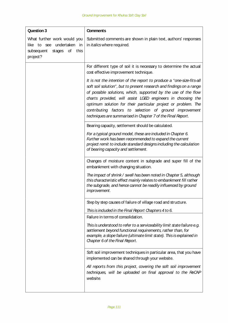
Ground Improvement for Khulna Soft Clay Soil
Page 111
Question 3
What further work would youlike to see undertaken insubsequent stages of thisproject?
Comments
Submitted comments are shown in plain text, authors’ responsesin italics where required.
For different type of soil it is necessary to determine the actualcost effective improvement technique.
It is not the intention of the report to produce a “one-size-fits-allsoft soil solution”, but to present research and findings on a rangeof possible solutions, which, supported by the use of the flowcharts provided, will assist LGED engineers in choosing theoptimum solution for their particular project or problem. Thecontributing factors to selection of ground improvementtechniques are summarised in Chapter 7 of the Final Report.
Bearing capacity, settlement should be calculated.
For a typical ground model, these are included in Chapter 6.Further work has been recommended to expand the currentproject remit to include standard designs including the calculationof bearing capacity and settlement.
Changes of moisture content in subgrade and super fill of theembankment with changing situation.
The impact of shrink / swell has been noted in Chapter 5, althoughthis characteristic effect mainly relates to embankment fill ratherthe subgrade, and hence cannot be readily influenced by groundimprovement.
Step by step causes of failure of village road and structure.
This is included in the Final Report Chapters 4 to 6.Failure in terms of consolidation.
This is understood to refer to a serviceability limit state failure e.g.settlement beyond functional requirements, rather than, forexample, a slope failure (ultimate limit state). This is explained inChapter 6 of the Final Report.
Soft soil improvement techniques in particular area, that you haveimplemented can be shared through your website.
All reports from this project, covering the soft soil improvementtechniques, will be uploaded on final approval to the ReCAPwebsite.

Ground Improvement for Khulna Soft Clay Soil
Page 112
Question 3
What further work would youlike to see undertaken insubsequent stages of thisproject?
Comments
Submitted comments are shown in plain text, authors’ responsesin italics where required.
Different test results like bone log, limit test, unconfinedcompression test results are done during sub-soil investigation.How these test results are interpreted to select a particulartechnique can be shared?
Further work has been recommended in the Final Report toexpand the current project remit to include standard designs,including how to determine parameters from ground data.
Question 4
Additional comments, feedbackand questions.
Comments
Submitted comments are shown in plain text, authors’ responsesin italics where required.
Improvement techniques regarding different type of foundationand structure chart should be incorporated for more information.
Charts for different engineering applications are included in theFinal Report. Further work has been recommended in the FinalReport to expand the current project remit to include standarddesignsNeed to know reliable and easy methods of sub-soil investigation.
Typical ground investigation methods for standard applicationsare included in Appendix K of the Final Report.Presently LGED is using micro pile and toe loading system theregion so this system to covered here.
This technique has not been mentioned to the author teamthroughout the research project and is not included. The use ofpalisade wall has been mentioned, but this is not a groundimprovement technique – it is a slope stability measure. Theauthorship team would welcome details of further methods beingtrialled by LGED or others in Bangladesh.
Most of the pictures attached in the presentation are the case ofnon-maintenance of proper slope in the road or approachembankment. There should be a comparison of cost whether soiltreatment or routine maintenance is cost effective or not.
The example used in the presentation concentrated on a singleground model – an approach embankment, as there wasinsufficient time to go through all applications. The Final Report
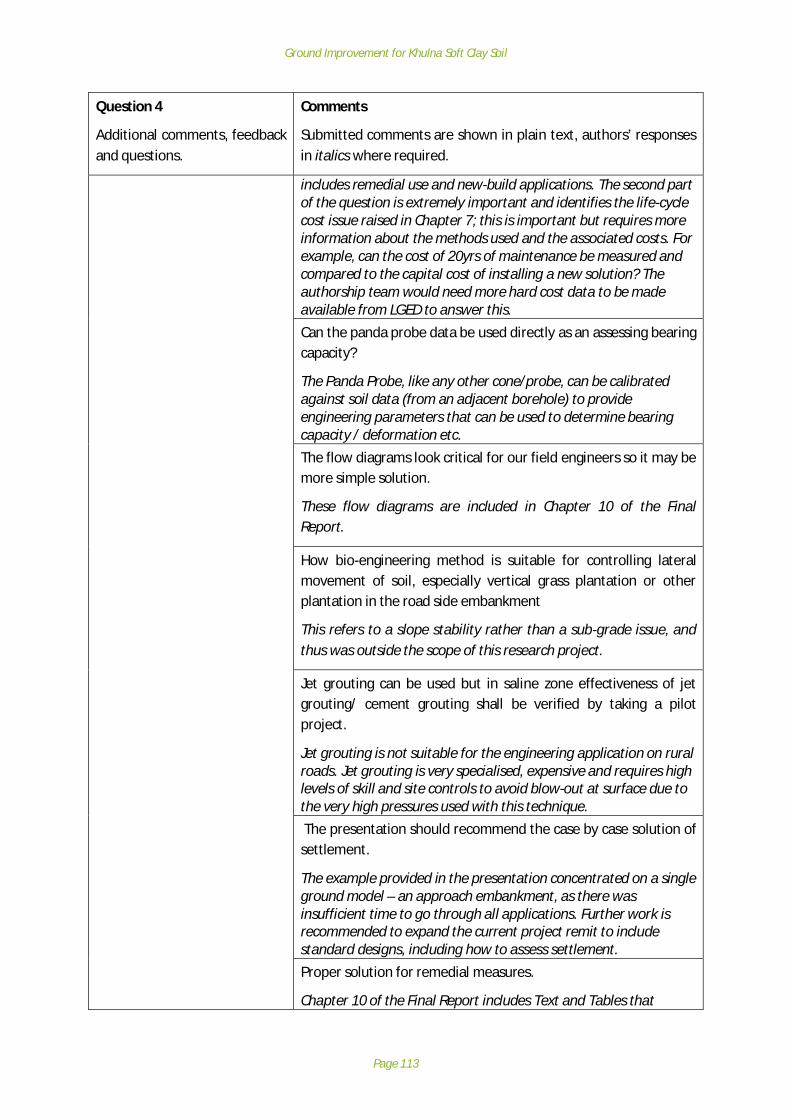
Ground Improvement for Khulna Soft Clay Soil
Page 113
Question 4
Additional comments, feedbackand questions.
Comments
Submitted comments are shown in plain text, authors’ responsesin italics where required.
includes remedial use and new-build applications. The second partof the question is extremely important and identifies the life-cyclecost issue raised in Chapter 7; this is important but requires moreinformation about the methods used and the associated costs. Forexample, can the cost of 20yrs of maintenance be measured andcompared to the capital cost of installing a new solution? Theauthorship team would need more hard cost data to be madeavailable from LGED to answer this.
Can the panda probe data be used directly as an assessing bearingcapacity?
The Panda Probe, like any other cone/probe, can be calibratedagainst soil data (from an adjacent borehole) to provideengineering parameters that can be used to determine bearingcapacity / deformation etc.The flow diagrams look critical for our field engineers so it may bemore simple solution.
These flow diagrams are included in Chapter 10 of the FinalReport.
How bio-engineering method is suitable for controlling lateralmovement of soil, especially vertical grass plantation or otherplantation in the road side embankment
This refers to a slope stability rather than a sub-grade issue, andthus was outside the scope of this research project.
Jet grouting can be used but in saline zone effectiveness of jetgrouting/ cement grouting shall be verified by taking a pilotproject.
Jet grouting is not suitable for the engineering application on ruralroads. Jet grouting is very specialised, expensive and requires highlevels of skill and site controls to avoid blow-out at surface due tothe very high pressures used with this technique. The presentation should recommend the case by case solution ofsettlement.
The example provided in the presentation concentrated on a singleground model – an approach embankment, as there wasinsufficient time to go through all applications. Further work isrecommended to expand the current project remit to includestandard designs, including how to assess settlement.Proper solution for remedial measures.
Chapter 10 of the Final Report includes Text and Tables that

Ground Improvement for Khulna Soft Clay Soil
Page 114
Question 4
Additional comments, feedbackand questions.
Comments
Submitted comments are shown in plain text, authors’ responsesin italics where required.
describe potential remedial measures to address specific defectsobserved. It is noted in the Report than ground improvementtechniques are difficult to implement for remedial applications(Section 10.2.1).Does the report consider swelling of soil?
The impact of shrink / swell has been noted in Chapter 5, althoughthis characteristic effect mainly relates to embankment fill ratherthe subgrade, and hence cannot be readily influenced by groundimprovement.What is the design site of these roads (long term traffic loads)
Traffic loading has not been considered in this project. Trafficloading is relevant to the embankment construction andserviceability of the surfacing (e.g wheel rutting), but has littleinfluence on the overall load applied to the sub-grade andimproved ground.
Conclusions
The Stakeholder Workshop was well attended, with a high level of engagement, interest, andexperience brought to the table from the assembled floor of experts and practitioners. Wheretechnical questions and comments were not directly answered in session, the comments raisedtypically focussed around the following key areas:
· Requirement for piloting to test the recommended ground improvement techniques;· Recommendation of alternative techniques: Most of these techniques had been considered
as part of the process under project in selecting techniques appropriate to the rural roadsenvironment, and in some cases (such as jet grouting), considered impractical for thiscontext. In others, useful comment has been made on the practicality of techniques, tofeed into the recommendations of the final report; and in all cases, the consultation washighly informative in understanding more the practical and operations preferences andexperience from LGED engineers;
· Requests for ongoing training and capacity building of design and constructionmethodologies for ground improvement techniques for the rural roads network;
All received comments have been carefully analysed and understood and relevant content includedin the project Final Report. Key themes identified above have been incorporated in therecommendations for ongoing work for the embedment and uptake of the project findings.

Ground Improvement for Khulna Soft Clay Soil
Page 115
Appendix C: Review of GI and lab testing in Bangladesh
Formation of boreholesThe manual percussion drilling method is predominantly used for ground investigation inBangladesh. The main reasons to use the manual percussion drilling method are the simplicity of theapparatus and availability of cheap labor to conduct the works. Recently due to the requirements ofsome consultants, rotary percussion is also now being employed by some Bangladesh siteinvestigation companies. The companies that now have rotary drilling facilities are privateorganizations and comprise:
§ Prosoil Foundation Consultant.§ ICON Engineering Services.§ DCL Companies.
During ground investigations conducted in Bangladesh, it is typical for SPT (Standard PenetrationTest) data to be recorded and for disturbed and undisturbed samples to be retrieved.
In-situ testingSome in-situ tests are also available and conducted in Bangladesh and these include:§ Dutch Cone Penetration Test.§ Plate Load Test.§ Screw Plate Load Test.§ Borehole Shear Test.§ Pressuremeter Test.§ Dynamic Cone Penetration (DPL, DPM and DPSH).
Available laboratory testing techniquesPredominantly in accordance with ASTM requirements – NB: There is no accreditation process toensure that other certification practices are acceptable).
Index & Physical properties:§ Specific Gravity.§ Unit weight (wet & dry).§ Void ratio (Specific Gravity & Unit Weight).§Moisture content.§ Liquid limit and Plastic limit.§ Linear Shrinkage.§ Shrinkage limit.§ Grain size analysis by wet sieving and Hydrometer.§ Organic matter content - Loss on ignition.§ Sand equivalent test.
Compaction and density tests:§Maximum and Minimum density of cohesionless soil.§ Standard Proctor Compaction test.§Modified Proctor Compaction test.
Permeability and seepage characteristics:§ Permeability of cohesive soil by 1-dimensional consolidation.§ Permeability of cohesionless soil (falling head)

Ground Improvement for Khulna Soft Clay Soil
Page 116
§ Permeability of cohesionless soil (constant head)
Consolidation and swelling characteristics:§ One dimensional consolidation (e - log p, Cc,Cr,Cv)§ Swelling Index / Swelling Pressure
Strength and deformation characteristics:§ Unconfined compression test§ Lab. California Bearing Ratio (CBR) of soils
Direct shear tests:§ Consolidated Drained test§ Consolidated quick test§ Unconsolidated quick test
Triaxial shear tests:§ Consolidated Drained compression test.§ Consolidated undrained compression test with pore pressure.§ Consolidated undrained compression test without pore pressure.§ Unconsolidated undrained compression test without pore pressure.§ Consolidated undrained extension test without pore pressure.§ Cyclic Triaxial Test.
Testing facilities available in KhulnaThree organizations have laboratory testing facilities available in Khulna and these are:1. Khulna University of Engineering and technology (KUET)2. Roads and Highways3. Local Government Engineering Department (LGED)
The abovementioned organizations have the facilities to conduct the following laboratory tests:§ Specific gravity.§ Unit weight (wet & dry).§ Void ratio (Specific gravity & Unit Weight).§ Moisture content.§ Liquid limit and Plastic limit.§ Linear Shrinkage.§ Shrinkage limit.§ Grain size analysis by wash sieving.§ Hydrometer, sieve analysis & specific gravity.

Ground Improvement for Khulna Soft Clay Soil
Page 117
Appendix D:Existing Borehole Data
SiteNumber Borehole Location
Depth mBGL) Distance fromobservational site (m)
3 Kalidaspur,ChandkhaliBazar, Paikgasa,Khulna.
21 ~3500
10 Amvita Matri Mondir,Amvita bazar, Dumuria,Khulna
21 ~300
11 Banda Bazar, Dumuria,Khulna
21 ~5600
12 Kudir Bot-tola, Jabusha,Rupsha, Khulna
51 ~4500
13 Terokhada, Khulna 21 ~300
15 Terokhada, Khulna(same as 13)
21 ~5000
21 Collage Road, Mongla,Bagerhat.
21 ~6000

A2
CLIENT : Orascom Telecom Bangladesh Limited.
PROJECT : Telecommunication Tower.
PROSOIL LOCATION: Kalidaspur,Chandkhali Bazar, Paikgasa, Khulna.
G. W. T : 2.0m below from E. G. L.
R. L.: On Road Level.
DATE OF BORING : 22-09-2013.
DEPTH OF BORING: 21.0m
BOREHOLE NO: BH-1
DISTURBEDSAMPLE
Clay %, Silt %, Sand %Max
m
Penetration
Grain Size Distribution, %
SPT VALUES( BLOWS / 300mm )
UNDISTURBEDSAMPLE
DEPTH (m)
BORELOG
SOIL STRATA
THICKNESS
12
.45
m
20
18
16
14
12
10
8
6
4
2
0
Black 10YR (2/1), highly Organic soil, PT
Gray 7.5YR (6/1), medium plasticity, soft to medium stiff, silty Clay, CL.
Brown 10YR (8/2), loose, silty Sand, SM.
Gray 7.5YR (5/1), medium plasticity, very soft to soft, silty Clay, CL.
MICACEOUS FINE SAND/SILT
UNDISTURBED SAMPLE
PEAT/HIGHLY ORGANIC SOIL
SAND
LEGEND FOR BORELOG AND GRAIN SIZE DISTRIBUTION (BASED ON 'ASTM CLASSIFICATION D-2487')
D-16
D-15
D-14
D-13
D-12
D-11
D-10
D-9
D-8
D-7
D-6
D-5
D-4
D-3
D-2
D-1
21
19
17
15
13
11
9
7
5
3
1
0 10 20 30 40 50 60 70 80
7
5
4
5
1
3
4
4
4
3
4
2
1
1
3
4
0 20 40 60 80 100
5.5
m1
.5m
2.0
m
SHALE
DISTURBED SAMPLE
SILTPLASTIC CLAY
N- BLOWS DELIVERED PER FOOT BY A 140 LB HAMMER FALLING 30 INCHES
MAXm PENETRATION= 50 BLOWS
AFTER 50 BLOWS PENETRATION DEPTH WERE MEASURED

A2
CLIENT : Orascom Telecom Bangladesh Limited.
PROJECT : Telecommunication Tower.
PROSOIL LOCATION: Amvita Matri Mondir, Amvita bazar, Dumuria, Khulna.
B. W. T : 1.00m below from E. G. L.
R. L.: On Road Level.
DATE OF BORING : 01-03-2014.
DEPTH OF BORING: 21.0m
BOREHOLE NO: BH-1
DISTURBEDSAMPLE
Clay %, Silt %, Sand %Max
m
Penetration
Grain Size Distribution, %
SPT VALUES( BLOWS / 300mm )
UNDISTURBEDSAMPLE
DEPTH (m)
BORELO
GSOIL STRATA
THICKNESS
20
18
16
14
12
10
8
6
4
2
0
Bluish Gray Gley2 (5/1), medium plasticity, soft to medium stiff, silty Clay, CL.
Gray 7.5YR (5/1), medium plasticity, very soft to soft, silty Clay, CL.
Brown 7.5YR (5/2), medium plasticity, very soft to soft, silty Clay, CL.
Bluish Gray Gley2 (5/1), medium plasticity, very soft to soft, silty Clay, CL.
MICACEOUS FINE SAND/SILT
UNDISTURBED SAMPLE
PEAT/HIGHLY ORGANIC SOIL
SAND
LEGEND FOR BORELOG AND GRAIN SIZE DISTRIBUTION (BASED ON 'ASTM CLASSIFICATION D-2487')
UD-1
UD-3
UD-2
D-16
D-15
D-14
D-13
D-12
D-11
D-10
D-9
D-8
D-7
D-6
D-5
D-4
D-3
D-2
D-1
21
19
17
15
13
11
9
7
5
3
1
0 10 20 30 40 50 60 70 80
12
9
5
8
1
1
2
3
3
3
4
2
2
1
4
3
0 20 40 60 80 100
7.5
m3
.5m
4.0
m6
.45
m
SHALE
DISTURBED SAMPLE
SILTPLASTIC CLAY
N- BLOWS DELIVERED PER FOOT BY A 140 LB HAMMER FALLING 30 INCHES
MAXm PENETRATION= 50 BLOWS
AFTER 50 BLOWS PENETRATION DEPTH WERE MEASURED

A2
CLIENT : Orascom Telecom Bangladesh Limited.
PROJECT : Telecommunication Tower.
PROSOIL LOCATION: Banda Bazar, Dumuria, Khulna.
B. W. T : 0.30m below from E. G. L.
R. L.: On Road Level.
DATE OF BORING : 14-03-2014.
DEPTH OF BORING: 21.0m
BOREHOLE NO: BH-1
DISTURBEDSAMPLE
Clay %, Silt %, Sand %Max
m
Penetration
Grain Size Distribution, %
SPT VALUES( BLOWS / 300mm )
UNDISTURBEDSAMPLE
DEPTH (m)
BORELO
GSOIL STRATA
THICKNESS
15
.0m
20
18
16
14
12
10
8
6
4
2
0
Gray 5Y (6/1), medium plasticity, very soft to very stiff, Clay, CL.
Brown 7.5Y (4/3), medium plasticity,very soft to soft, Clay, CL.
Dark Gray 5Y (3/1), dense to very dense, fine Sand, SM.
MICACEOUS FINE SAND/SILT
UNDISTURBED SAMPLE
PEAT/HIGHLY ORGANIC SOIL
SAND
LEGEND FOR BORELOG AND GRAIN SIZE DISTRIBUTION (BASED ON 'ASTM CLASSIFICATION D-2487')
UD-3
UD-2
UD-1
D-16
D-15
D-14
D-13
D-12
D-11
D-10
D-9
D-8
D-7
D-6
D-5
D-4
D-3
D-2
D-1
21
19
17
15
13
11
9
7
5
3
1
0 10 20 30 40 50 60 70 80
31
25
12
18
3
3
1
2
3
3
4
1
1
2
2
3
0 20 40 60 80 100
3.4
5m
3.0
m
SHALE
DISTURBED SAMPLE
SILTPLASTIC CLAY
N- BLOWS DELIVERED PER FOOT BY A 140 LB HAMMER FALLING 30 INCHES
MAXm PENETRATION= 50 BLOWS
AFTER 50 BLOWS PENETRATION DEPTH WERE MEASURED
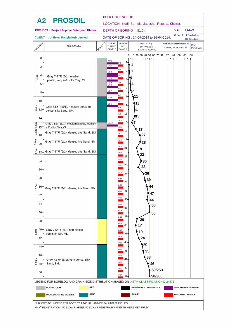
A2
CLIENT : Unilever Bangladesh Limited.
PROJECT : Project Popular Detergent, Khulna.
PROSOILLOCATION : Kudir Bot-tola, Jabusha, Rupsha, Khulna.
G. W. T : 1.0m below from E.G.L.
R. L. : 2.51m
DATE OF BORING : 24-04-2014 to 26-04-2014.
DEPTH OF BORING : 51.0m
BOREHOLE NO: 01
UNDISTURBEDSAMPLE
DISTURBED
SAMPLEClay %, Silt %, Sand %
Maxm
Penetration
Grain Size Distribution, %
SPT VALUES( BLOWS / 300mm )
DEPTH (m)
BORELO
GSOIL STRATA
THICKNESS
50
48
46
44
42
40
38
36
34
32
30
28
26
24
22
20
18
16
14
12
10
8
6
4
2
0
Gray 7.5YR (5/1), very dense, silty Sand, SM.
Gray 7.5YR (5/1), non plastic, very stiff, Silt, ML.
Gray 7.5YR (5/1), dense, fine Sand, SM.
Gray 7.5YR (5/1), dense, silty Sand, SM.
Gray 7.5YR (5/1), dense, fine Sand, SM.
Gray 7.5YR (5/1), dense, silty Sand, SM.
Gray 7.5YR (5/1), medium plastic, medium stiff, silty Clay, CL.
Gray 7.5YR (5/1), medium dense todense, silty Sand, SM.
MICACEOUS FINE SAND/SILT
UNDISTURBED SAMPLEPEAT/HIGHLY ORGANIC SOIL
SAND
LEGEND FOR BORELOG AND GRAIN SIZE DISTRIBUTION (BASED ON 'ASTM CLASSIFICATION D-2487')
UD-10
UD-9
UD-8
UD-7
UD-6UD-5
UD-4
UD-3
UD-2
UD-1
D-32
D-24
D-33
D-25
D-34
D-31
D-26
D-27
D-30
D-29
D-28
D-23
D-22
D-21
D-20
D-19
D-18
D-17
D-16
D-15
D-14
D-13
D-12
D-11
D-10
D-9
D-8
D-7
D-6
D-5
D-4
D-3
D-2
D-1
51
49
47
45
43
41
39
37
35
33
31
29
27
25
23
21
19
17
15
13
11
9
7
5
3
1
0 10 20 30 40 50 60 70 80
50/200
50/250
46
38
35
32
24
19
17
20
50
50
44
47
30
44
39
36
23
23
28
19
11
13
14
15
7
17
27
3
4
5
1
1
0 20 40 60 80 100
1.5
m1.5
m6.0
m15.0
m1.5
m3.0
m9.0
m6.0
m7.9
5m
SHALE DISTURBED SAMPLE
SILTPLASTIC CLAY
N- BLOWS DELIVERED PER FOOT BY A 140 LB HAMMER FALLING 30 INCHES
MAXm PENETRATION= 50 BLOWS. AFTER 50 BLOWS PENETRATION DEPTH WERE MEASURED
Gray 7.5YR (5/1), medium plastic, very soft, silty Clay, CL.
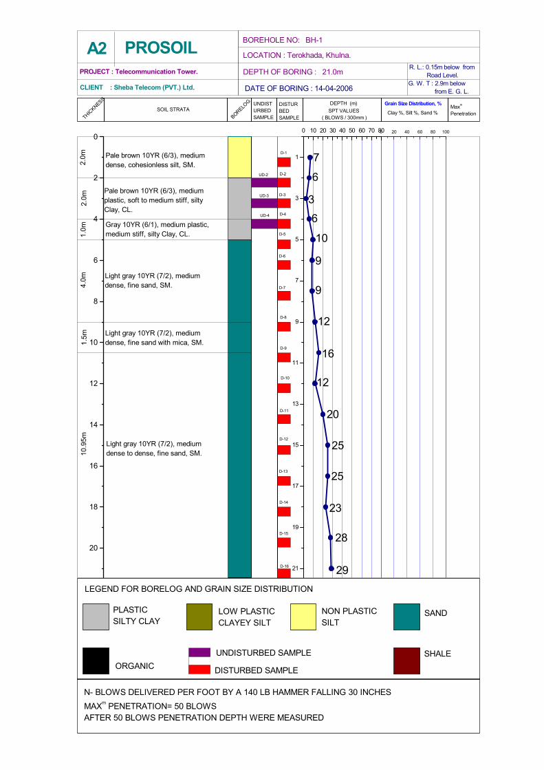
A2
CLIENT : Sheba Telecom (PVT.) Ltd.
PROJECT : Telecommunication Tower.
PROSOIL LOCATION : Terokhada, Khulna.
G. W. T : 2.9m below from E. G. L.
R. L.: 0.15m below from Road Level.
DATE OF BORING : 14-04-2006
DEPTH OF BORING : 21.0m
BOREHOLE NO: BH-1
DISTURBEDSAMPLE
Clay %, Silt %, Sand %Maxm Penetration
Grain Size Distribution, % SPT VALUES( BLOWS / 300mm )
UNDISTURBEDSAMPLE
DEPTH (m)
BORELOG
SOIL STRATATHIC
KNESS
1.5m
1.0m
2.0m
4.0m
2.0m
10.9
5m
20
18
16
14
12
10
8
6
4
2
0
Light gray 10YR (7/2), medium dense to dense, fine sand, SM.
Light gray 10YR (7/2), medium dense, fine sand with mica, SM.
Pale brown 10YR (6/3), medium plastic, soft to medium stiff, silty Clay, CL.
Pale brown 10YR (6/3), medium dense, cohesionless silt, SM.
Gray 10YR (6/1), medium plastic, medium stiff, silty Clay, CL.
Light gray 10YR (7/2), medium dense, fine sand, SM.
LOW PLASTIC CLAYEY SILT
UNDISTURBED SAMPLEORGANIC
SAND
LEGEND FOR BORELOG AND GRAIN SIZE DISTRIBUTION
UD-4
UD-2
UD-3
D-16
D-15
D-14
D-13
D-12
D-11
D-10
D-9
D-8
D-7
D-6
D-5
D-4
D-3
D-2
D-1
21
19
17
15
13
11
9
7
5
3
1
0 10 20 30 40 50 60 70 80
29
28
25
23
9
9
12
16
12
20
25
3
6
10
6
7
0 20 40 60 80 100
SHALE
DISTURBED SAMPLE
NON PLASTIC SILT
PLASTIC SILTY CLAY
N- BLOWS DELIVERED PER FOOT BY A 140 LB HAMMER FALLING 30 INCHESMAXm PENETRATION= 50 BLOWSAFTER 50 BLOWS PENETRATION DEPTH WERE MEASURED

A2
CLIENT : Orascom Telecom Bangladesh Limited.
PROJECT : Telecommunication Tower.
PROSOILLOCATION: Collage Road, Mongla, Bagerhat.
G. W. T : On E. G. L.
R. L.: 0.31m below from Road Level.
DATE OF BORING : 25-09-2013.
DEPTH OF BORING: 21.0m
BOREHOLE NO: BH-1
DISTURBEDSAMPLE
Clay %, Silt %, Sand %Max
m
Penetration
Grain Size Distribution, %
SPT VALUES( BLOWS / 300mm )
UNDISTURBEDSAMPLE
DEPTH (m)
BORELOG
SOIL STRATA
THICKNESS
20
18
16
14
12
10
8
6
4
2
0
Gray 10YR (5/1), medium dense to dense, fine Sand, SM.
Gray 10YR (5/1), very loose to medium dense, silty Sand, SM.
Gray 10YR (5/1), medium plasticity, very soft to medium stiff, silty Clay, CL.
MICACEOUS FINE SAND/SILT
UNDISTURBED SAMPLE
PEAT/HIGHLY ORGANIC SOIL
SAND
LEGEND FOR BORELOG AND GRAIN SIZE DISTRIBUTION (BASED ON 'ASTM CLASSIFICATION D-2487')
UD-1
UD-2
D-16
D-15
D-14
D-13
D-12
D-11
D-10
D-9
D-8
D-7
D-6
D-5
D-4
D-3
D-2
D-1
21
19
17
15
13
11
9
7
5
3
1
0 10 20 30 40 50 60 70 80
25
23
19
22
4
3
2
4
8
10
18
6
4
4
1
1
0 20 40 60 80 100
9.0
m3
.0m
9.4
5m
SHALE
DISTURBED SAMPLE
SILTPLASTIC CLAY
N- BLOWS DELIVERED PER FOOT BY A 140 LB HAMMER FALLING 30 INCHES
MAXm PENETRATION= 50 BLOWS
AFTER 50 BLOWS PENETRATION DEPTH WERE MEASURED

Ground Improvement for Khulna Soft Clay Soil
Page 118
Appendix E: Site Location plans, observations and test data
Site 3 Assasuni
Site 3: Road287042008
Ground Improvement for Khulna Soft Clay Soil
Page 119
Site 3 DescriptionSite 3 is a single lane carriageway with a flexible bituminous pavement and brick lined edging / kerb.The embankment is made of soft clay and is planted with planned mixed vegetation. The vegetationwas planted 3 years ago at 1.8m centres for slope protection. The vegetation includes Raintree,Koroi and Babla trees, whilst natural grasses and shrubs are also present.
The road is a Upazilla category road connecting to another sub-district. The carriageway isapproximately 3 m wide and the embankment is approximately 0.9 m high. Slope angles wereobserved to vary between 75 and 85 degrees. The slope is at a slacker angle on the RHS of road thanLHS. The embankment slope is particularly steep and with minor vegetation in the approach to thewing wall of a bridge / culvert structure. There is a clear loss of soil behind the concrete culvertheadwall.
There are heavy vehicles using the road though it was not constructed to accommodate heavytraffic. The passage of heavy vehicles has likely contributed to observed deformation of thecarriageway either side of the road centre line and in the run up to a bridge / culvert. Patch repairsand sealed seams are evident in the carriageway surface. The blacktop is extremely badly damagedto the point of being lost entirely over a large stretch of road. Brick kerbing is present whereblacktop remains. The resulting surface appears muddy and with tyre tracks and rutting
It is clear that vehicles are passing beyond edge of road pavement and brick kerb causing rutting anddamage to the soft soils of the verge and slope crest. Reed bales (or similar) have been laid downalong the edge of the poor side of the carriageway, in an attempt to temporarily improve the surfaceconditions and are likely to be masking further problems.
In some places, there is embankment toe protection provided in the form of precast driven piles(~3m long and at 0.9m centres) bolted with vertical concrete slabs in between two piles. This slopetoe protection appears to be failing and leaning outwards – seemingly as the embankment spreads.
It is reported that water levels come close to the pavement in the rainy season. Because of fishfarming, the water level differs on each side of the road embankment.
Site 3 Investigation and testingInvestigation at the site comprised 3No. trial pits and 3No. Panda Probes. The site investigationlocations are detailed below:

Ground Improvement for Khulna Soft Clay Soil
Page 120
Site 3: Assasuni
The factual data obtained from the site investigations is presented below.
N

Ground Improvement for Khulna Soft Clay Soil
Page 121
Summary of soil sampling for Site 3 Assasuni
Site no. 3: Assasuni (Road: 287042008)
Trial Pit 1
Lithology:
The soil sample contains Very Fine Sand ofReddish Brown colour. The Sand is Loose andcontains sufficient amount of Gravels withinit. But those gravels are may be mixed fromthe pavement material because some of themcontain coats of Bitumen.
Trial Pit 2
Lithology:
The soil sample is Gray in colour withModerate Plasticity. It shows ExtensiveReddish and Dark materials. The reddish spotsare ferruginous materials and dark spots arecarbonaceous materials. There are also somestraw colour features within the soil whichmay form by the direct decomposition oforganic materials.
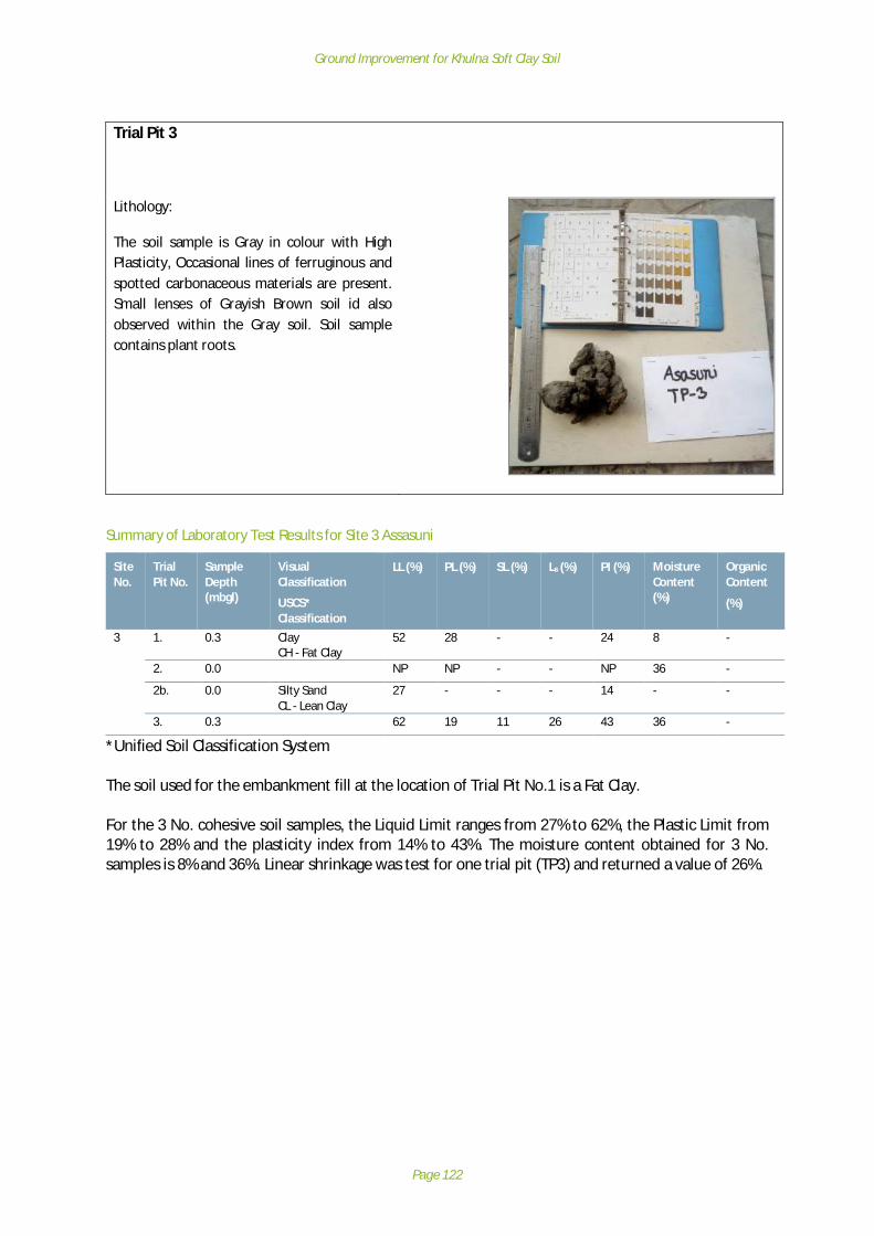
Ground Improvement for Khulna Soft Clay Soil
Page 122
Trial Pit 3
Lithology:
The soil sample is Gray in colour with HighPlasticity, Occasional lines of ferruginous andspotted carbonaceous materials are present.Small lenses of Grayish Brown soil id alsoobserved within the Gray soil. Soil samplecontains plant roots.
Summary of Laboratory Test Results for Site 3 Assasuni
*Unified Soil Classification System
The soil used for the embankment fill at the location of Trial Pit No.1 is a Fat Clay.
For the 3 No. cohesive soil samples, the Liquid Limit ranges from 27% to 62%, the Plastic Limit from19% to 28% and the plasticity index from 14% to 43%. The moisture content obtained for 3 No.samples is 8% and 36%. Linear shrinkage was test for one trial pit (TP3) and returned a value of 26%.
SiteNo.
TrialPit No.
SampleDepth(mbgl)
VisualClassification
USCS*Classification
LL (%) PL (%) SL (%) Ls (%) PI (%) MoistureContent(%)
OrganicContent
(%)
3 1. 0.3 ClayCH - Fat Clay
52 28 - - 24 8 -
2. 0.0 NP NP - - NP 36 -
2b. 0.0 Silty SandCL - Lean Clay
27 - - - 14 - -
3. 0.3 62 19 11 26 43 36 -

Ground Improvement for Khulna Soft Clay Soil
Page 123
PSD Plot for Sample 2, Site 3
Summary of Panda Probe Results for Site 3 Assasuni
SiteNumber
SiteName
ProbeNumber
FinalDepth(mbgl)
EmbankmentHeight
(m)
Summary of Penetration
3 Assasuni 1 4.7 1.2 Reduction in soil strength below road surface from 0 to 0.9mbgl, before steady increase to end of probe
2 4.7 1.2 Sharp increase at shallow depth (in road formation)followed by reduction in soil strength below road surfacefrom 0.1 to 0.9 mbgl, before steady increase to 2.0m wherestrength levels to end of probe
3 4.5 1.1 General drop in soil strength to 1.5mbgl, before rising to asteady resistance value at 2.0mbgl.

Ground Improvement for Khulna Soft Clay Soil
Page 124
Cone Resistance Plot - Site 3 Assasuni 287042008: Test 1

Ground Improvement for Khulna Soft Clay Soil
Page 125
Cone Resistance Plot - Site 3 Assasuni 287042008:Test 2

Ground Improvement for Khulna Soft Clay Soil
Page 126
Cone Resistance Plot - Site 3 Assasuni 287042008: Test 3

Ground Improvement for Khulna Soft Clay Soil
Page 127
Site 10 Dumuria – A
Site 10 DescriptionSite 10 is a single-track road with a flexible bituminous carriageway. The carriageway isapproximately 3.6 m wide. The road embankment is constructed from predominantly organic soiland has uneven slopes that vary in angle between 45 and 60 degrees. The side slopes are vegetatedwith grasses, herbs and mahogany and Koroi trees and show sign erosion.
The road pavement shows clear signs of distress and cracking. The cracking is most severe on theslope side of the carriageway which displays much longitudinal cracking. There are patches ofblacktop loss evident in the road surface.
In many places, there is embankment protection provided at the toe of the embankment using 3 mlong precast driven pile set out at 0.9 m centres with vertical concrete slabs bolted between a 2 pilearrangement.
The local LGED Engineer has indicated that water levels come close to the pavement surface in therainy season. Shrimp farming is conducted on either side of the carriageway. There are culverts inthe road embankment for cross drainage.
Site 10 Investigation and testingInvestigation at the site comprised 3 No. trial pits and 3 No. Panda Probes. The site investigationlocations are detailed below:

Ground Improvement for Khulna Soft Clay Soil
Page 128
Site 10: Dumuria A
The factual data obtained from the site investigations is presented below.
N

Ground Improvement for Khulna Soft Clay Soil
Page 129
Summary of soil sampling for Site 10 Dumuria A
Site no. 10: Dumuria A (Road 247302001)
Trial Pit 1
Lithology:
bag 1: The soil is Gray colour non-plastic ClayeySilt and it contains brick fragments and plantroots.
bag 2: Grayish Brown Sandy Silt with spottedcarbonaceous materials and plant roots.
bag 3: Grayish Brown Sandy Silt.
Trial Pit 2
Lithology:
bag 1: Grayish Brown very fine Silty Clay withplant roots.
bag 2: Grayish Brown Sandy Silt with plantroots.
Bag 3: Brown very fine Sandy Silt with plantroots.

Ground Improvement for Khulna Soft Clay Soil
Page 130
Trial Pit 3
Lithology:
bag 1: Grayish Brown Sandy Silt, which containsplant roots, shells, and partly decomposedwood fragments.
bag 2: Brown very fine Sandy Silt with plantroots and shells.
bag 3: Brown Sandy Silts with plant roots andburrows.
bag 4: Dark Gray plastic Silty Clay with brickfragments, plant roots and shells.
Summary of Laboratory Test Results for Site 10 Dumuria A
*Unified Soil Classification System
The material sampled from the 3 No. trial pits at Site 10 – Dumuria A was very consistent, consistingof a Lean Clay and a Lean Clay with Sand. The Liquid Limit ranged between 44% and 49%, the PlasticLimit ranged between 20% and 21% whilst the Plasticity Index ranged between 16% and 28%. TheMoisture Content of the 3 No. samples ranged between 13% and 27% whilst the Organic Contentranged between 7% and 9%. One linear shrinkage test was conducted on sample from TP1 andreturned a value of 18%.
SiteNo.
TrialPit No.
SampleDepth(mbgl)
VisualClassification
USCS*Classification
LL (%) PL (%) SL (%) Ls (%) PI (%) MoistureContent(%)
OrganicContent
(%)
10 1. 0.25 ClayCL - Lean Clay
47 21 14 18 16 26 6
1b 0.25 ClayCL – Lean Clay
44 23 - - 21 - -
2. 0.25 ClayCL - Lean Clay
49 21 - - 28 27 9
3. 0.3 ClayCL - Lean Clay withSand
46 20 - - 26 13 7
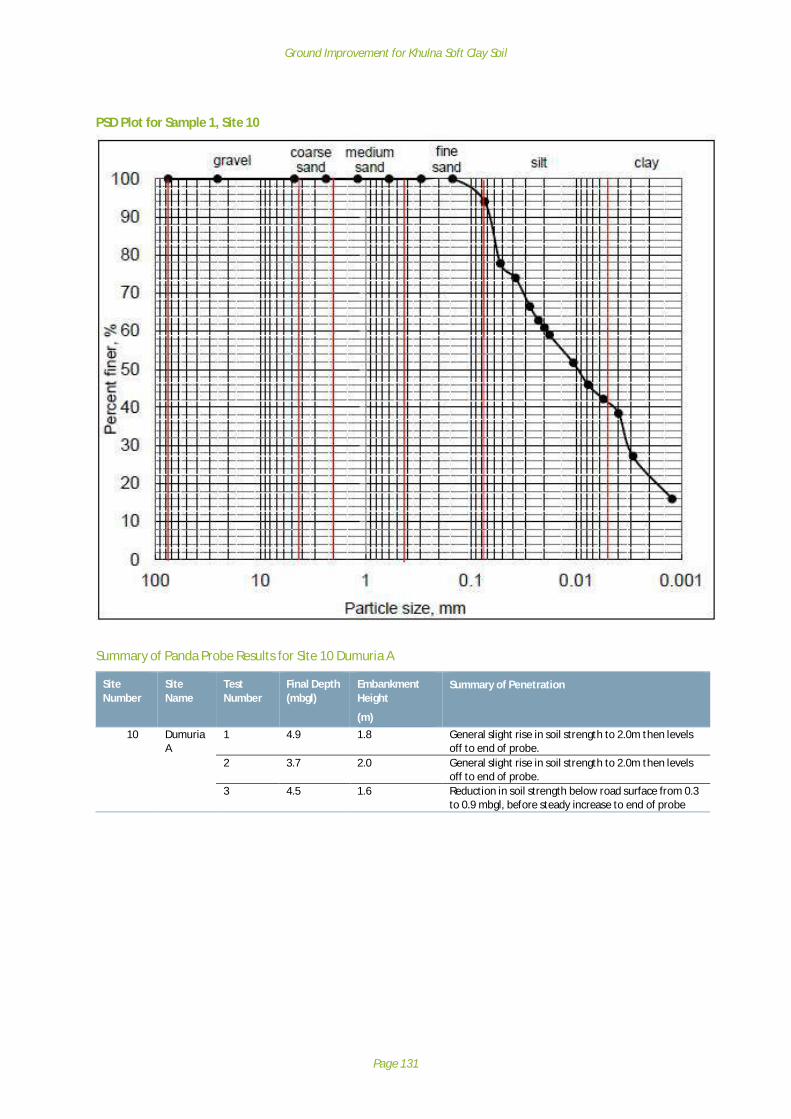
Ground Improvement for Khulna Soft Clay Soil
Page 131
PSD Plot for Sample 1, Site 10
Summary of Panda Probe Results for Site 10 Dumuria A
SiteNumber
SiteName
TestNumber
Final Depth(mbgl)
EmbankmentHeight
(m)
Summary of Penetration
10 DumuriaA
1 4.9 1.8 General slight rise in soil strength to 2.0m then levelsoff to end of probe.
2 3.7 2.0 General slight rise in soil strength to 2.0m then levelsoff to end of probe.
3 4.5 1.6 Reduction in soil strength below road surface from 0.3to 0.9 mbgl, before steady increase to end of probe

Ground Improvement for Khulna Soft Clay Soil
Page 132
Site 10 Dumuria – Site A 247302001: Test 1

Ground Improvement for Khulna Soft Clay Soil
Page 133
Site 10 Dumuria – Site A 247302001: Test 2

Ground Improvement for Khulna Soft Clay Soil
Page 134
Site 10 Dumuria – Site A 247302001: Test 3

Ground Improvement for Khulna Soft Clay Soil
Page 135
Site 11 Dumuria - B
Site 11 DescriptionSite 11 is a single lane carriageway with a flexible bituminous pavement. The carriageway isapproximately 3m wide.
The embankment is constructed from predominantly organic soil. The slopes were observed to beheavily damaged and are planted with grasses, herbs, and various species of trees. Some trees areleaning outwards from embankment at an angle of approximately 80 degrees. Zones of pavementlost are visible along length of the carriageway. A large zone of pavement failure corresponds with abulging of the slope toe line – likely due to a relaxation of the embankment material and / orspreading under self-loading and passing vehicle loads.
In many places, there is embankment protection provided at the toe of the embankment in the formof 3m long precast driven piles set out at 0.9m centres with vertical concrete slabs bolted between a2-pile arrangement.
The local LGED Engineer reports that water levels come very close to the pavement surface in therainy season. Shrimp farming is conducted on both sides of the embankment. There are culverts inthe embankment for cross drainage.

Ground Improvement for Khulna Soft Clay Soil
Page 136
Site 11 Investigation and testingInvestigation at the site comprised 3 No. trial pits and 3 No. Panda Probes. The site investigationlocations are detailed below:
Site 11: Dumuria B
1. Lateral spreading of the embankments2. (Site 11 – 247303003)
N

Ground Improvement for Khulna Soft Clay Soil
Page 137
Summary of soil sampling for Site 11 Dumuria B
Site no. 11: Dumuria B (Road 247303003)
Trial Pit 1
Lithology:
Bag 1: The soil sample is dark Gray Clay whichshows high plasticity. Some reddish Brown toBrown Clayey layers are also present within thesoil.
Bag 2: The soil is dark Gray Silty Clay with highplasticity, which contains black layers of soilsthat may be carbonaceous material rich soil.
Trial Pit 1a (on embankment)
Lithology: Dark Gray Clay that shows highplasticity and contains plant roots.

Ground Improvement for Khulna Soft Clay Soil
Page 138
Trial Pit 2
Lithology: Dark Gray medium plastic Clay withminor Silt with plant roots & shells.
Trial Pit 3
Lithology: Dark Gray medium plastic Silty Claywhich contains plant roots.
Summary of Laboratory Test Results for Site 11 Dumuria B
*Unified Soil Classification System
The material sampled from the 3 No. trial pits at Site 11 – Dumuria B was very consistent, beingclassified as a Fat Clay and a Fat Clay with Sand.
SiteNo.
TrialPit No.
SampleDepth(mbgl)
VisualClassification
USCS*Classification
LL (%) PL (%) SL (%) Ls (%) PI (%) MoistureContent(%)
OrganicContent
(%)
11 1. 0.2 ClayCH – Fat Clay withSand
49 25 - - 27 28 2
2. 0.3 ClayCH - Fat Clay
58 25 - - 33 30 5
3. 0.3 ClayCH - Fat Clay
59 25 13 22 34 33 7
3b. 0.3 ClayCH – Fat Clay
79 - - - 52 - -
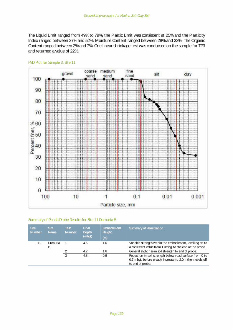
Ground Improvement for Khulna Soft Clay Soil
Page 139
The Liquid Limit ranged from 49% to 79%, the Plastic Limit was consistent at 25% and the PlasticityIndex ranged between 27% and 52%. Moisture Content ranged between 28% and 33%. The OrganicContent ranged between 2% and 7%. One linear shrinkage test was conducted on the sample for TP3and returned a value of 22%.
PSD Plot for Sample 3, Site 11
Summary of Panda Probe Results for Site 11 Dumuria B
SiteNumber
SiteName
TestNumber
FinalDepth(mbgl)
EmbankmentHeight
(m)
Summary of Penetration
11 DumuriaB
1 4.5 1.6 Variable strength within the embankment, levelling off toa consistent value from 1.0mbgl to the end of the probe.
2 4.2 1.6 General slight rise in soil strength to end of probe.3 4.8 0.9 Reduction in soil strength below road surface from 0 to
0.7 mbgl, before steady increase to 2.0m then levels offto end of probe.

Ground Improvement for Khulna Soft Clay Soil
Page 140
Site 11 Dumuria – Site B 247303003: Test 1
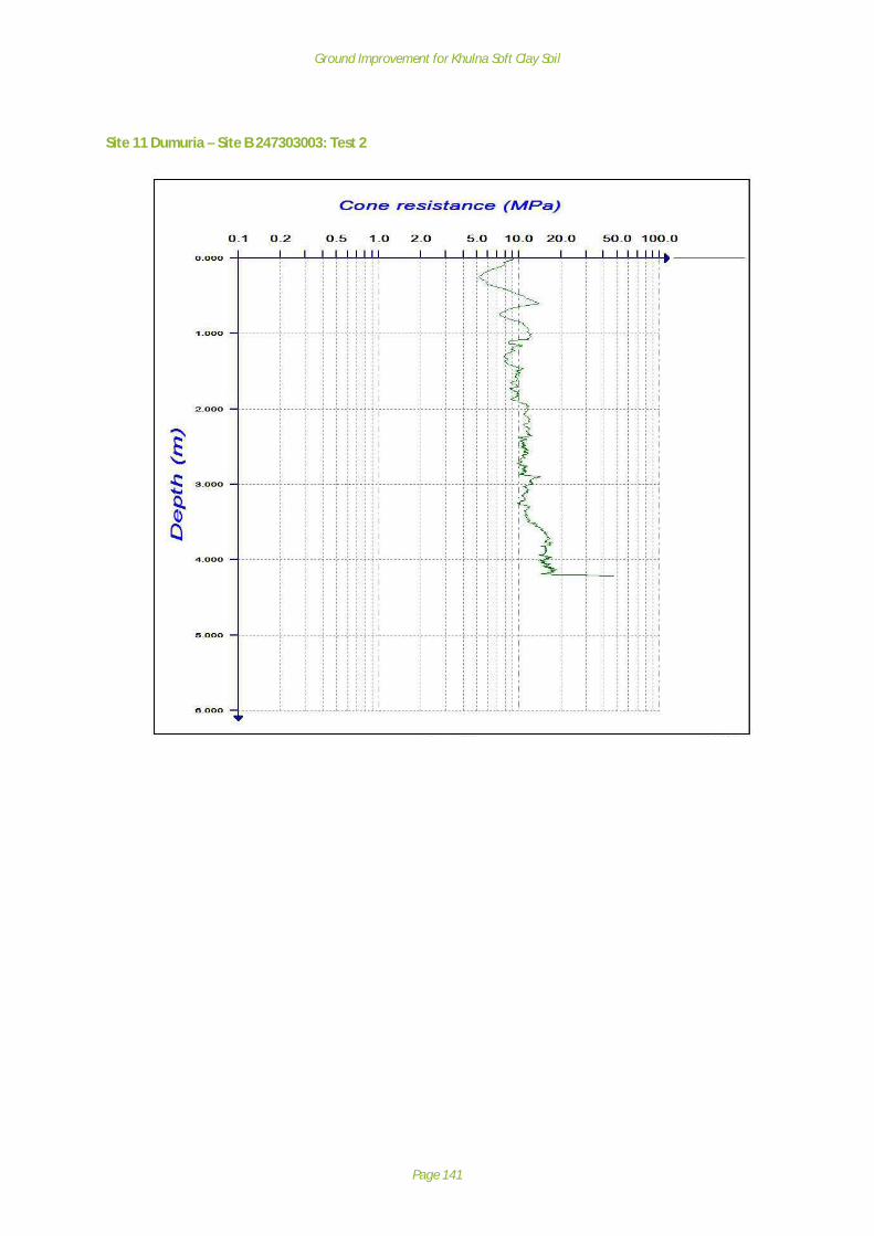
Ground Improvement for Khulna Soft Clay Soil
Page 141
Site 11 Dumuria – Site B 247303003: Test 2

Ground Improvement for Khulna Soft Clay Soil
Page 142
Site 11 Dumuria – Site B 247303003: Test 3

Ground Improvement for Khulna Soft Clay Soil
Page 143
Site 12 Rupsa
Site 12 DescriptionSite 12 is a single-track carriageway with a flexible bituminous pavement over a herringbone bricksubbase. The carriageway is approximately 3.6 m wide with soft shoulders.
The embankment is constructed from organic clay at the bottom and silty clay at the top. Theembankment slopes were assessed to be extensively damaged. The side slopes are vegetated withgrasses, herbs and mahogany and Shihu trees.
The carriageway shows significant deformation in wheel tracks with associated degradation of theblacktop. There is a large zone where the blacktop appears to be destroyed. Water is collecting inwheel ruts and causing localised softening that is exacerbating the degradation of the runningsurface. Heavily loaded wagons use the road and are evidently causing considerable damage.Longitudinal cracking is present in pavement surface associated with settlement of the wheel tracks.The road meets a bridge / culvert structure; there is no significant differential settlement betweenthe approach ramp earthwork and the structure itself.
In many places, there is embankment protection provided at the toe of the embankment in the formof 3 m long precast driven piles set out at 0.9 m centres with vertical concrete slabs bolted betweena 2-pile arrangement. This embankment toe protection has failed. A large zone of pavementdegradation corresponds with a zone where the toe reinforcement exhibits major serviceabilityfailure. A zone of pavement degradation corresponds with a section of embankment slope on whichno trees are present with a predominantly grass cover.

Ground Improvement for Khulna Soft Clay Soil
Page 144
The local LGED Engineer reports that the water level comes very close to the pavement surface inthe rainy season. Shrimp farming is conducted on both sides of the road embankment. There areculverts in the embankment for cross drainage.
Site 12 Investigation and testingInvestigation at the site comprised 3 No. trial pits and 3 No. Panda Probes. The site investigationlocations are detailed below:
Site 12: Rupsa
N

Ground Improvement for Khulna Soft Clay Soil
Page 145
Summary of soil sampling for Site 12 Rupsa
Site no. 12: Rupsa (Road 247752009)
Trial Pit 1
Lithology:
Bag 1: The soil sample is dark Gray Clayey Siltand it contains plant roots, brick fragments andshells of different organisms.
Bag 2: The soil sample is Gray medium plasticSilty Clay. Plant roots and shells of organismsare present.
Bag 3: The soil sample is dark Gray non-plasticClayey Silt which contains plant roots and shellsof organisms.
Trial Pit 2
Lithology: The soil sample is dark Gray Clay withminor amount of fine Sand. The Clay showsmoderate plasticity and contain plant roots,brick fragments.
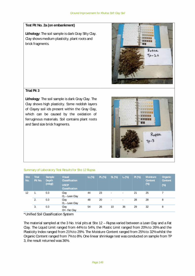
Ground Improvement for Khulna Soft Clay Soil
Page 146
Test Pit No. 2a (on embankment)
Lithology: The soil sample is dark Gray Silty Clay.Clay shows medium plasticity, plant roots andbrick fragments.
Trial Pit 3
Lithology: The soil sample is dark Gray Clay. TheClay shows high plasticity. Some reddish layersof Clayey soil ids present within the Gray Clay,which can be caused by the oxidation offerruginous materials. Soil contains plant rootsand Sand size brick fragments.
Summary of Laboratory Test Results for Site 12 Rupsa
*Unified Soil Classification System
The material sampled at the 3 No. trial pits at Site 12 – Rupsa varied between a Lean Clay and a FatClay. The Liquid Limit ranged from 44% to 54%, the Plastic Limit ranged from 20% to 26% and thePlasticity Index ranged from 21% to 29%. The Moisture Content ranged from 25% to 32% whilst theOrganic Content ranged from 7% to 8%. One linear shrinkage test was conducted on sample from TP3, the result returned was 36%.
SiteNo.
TrialPit No.
SampleDepth(mbgl)
VisualClassification
USCS*Classification
LL (%) PL (%) SL (%) Ls (%) PI (%) MoistureContent(%)
OrganicContent
(%)
12 1. 0.3 ClayCL – Lean Clay
44 23 - - 21 25 7
2. 0.3 ClayCL – Lean Clay
48 20 - - 28 28 8
3. 0.3 ClayCH - Fat Clay
54 26 10 36 29 32 8

Ground Improvement for Khulna Soft Clay Soil
Page 147
Summary of Panda Probe Results for Site 12 Rupsa
Site 12 Rupsa 47752009:– Test 1
SiteNumber
SiteName
TestNumber
FinalDepth(mbgl)
EmbankmentHeight
(m)
Summary of Penetration
12 Rupsa 1 4.6 0.4 General slight rise in soil strength to end of probe. Zone ofreduced strength from 0.6 to 0.9mbgl
2 4.5 1.5 Reduction in soil strength below road surface from 0 to 0.7mbgl, before steady increase to 3.0m then slight reductionto end of probe.
3 4.8 1.8 Reduction in soil strength below road surface from 0.1 to0.9 mbgl, before steady increase to 1.8 m then levels off toend of probe.

Ground Improvement for Khulna Soft Clay Soil
Page 148
Site 12 Rupsa 247752009: Test 2

Ground Improvement for Khulna Soft Clay Soil
Page 149
Site 12 Rupsa 247752009: Test 3

Ground Improvement for Khulna Soft Clay Soil
Page 150
Site 15 Terokhada - A
Site 15 DescriptionSite 15 is a single-track carriageway with a flexible bituminous pavement. The carriageway isapproximately 3 m with a soft shoulder. The embankment is constructed from organic clay at thebottom and silty clay at the top. The side slopes of the embankment are vegetated with grasses,herbs and trees of various species.
The road has significantly settled on the slope / water side of the carriageway and a large area ofpavement has been lost. The road is being trafficked by wagons and deformation of the road alongthe wheel tracks is evident. Vehicles are also pulling onto the verge to allow other vehicles to passwhich is damaging the edge of the pavement construction and the crest of the slope. There issignificant loss of pavement on a section of embankment where there are no trees present on theLHS slope. The road is muddy with deep wheel ruts which hold moisture and cause localisedsoftening, exacerbating the issues.
The toe of the slope has the typical driven pile and board support arrangement with again is leaningout towards the water.
The local LGED Engineer reports that water levels come close to the pavement surface in the rainyseason. There are culverts in the embankment for cross drainage.
Site 15 Investigation and testingInvestigation at the site comprised 2 No. trial pits and 2 No. Panda Probes. The site investigationlocations are detailed below:

Ground Improvement for Khulna Soft Clay Soil
Page 151
Site 15: Terokhada A
Summary of soil sampling for Site 15 Terokhada A
Site no. 15: Terokhada A (Road 247942010)
Trial Pit 1
Lithology:
Brown Sandy Silt with plant root partlydecomposed wood fragments.
N

Ground Improvement for Khulna Soft Clay Soil
Page 152
Trial Pit 2
Lithology: The soil is Grayish Brown very fineSandy Silt with plastic Clayey soil and plant roots.
Summary of Laboratory Test Results for Site 15 Terokhada A
*Unified Soil Classification System
The samples retrieved from the 2 No. trial pits at Site 15 – Terokhada A were extremely consistent.Both samples were classified as Lean Clay.
The Liquid Limit ranged from 41% to 42%, the Plastic Limit was consistent at 21% and the PlasticityIndex ranged from 20% to 21%. The Moisture Content ranged from 14% to 19%.
Summary of Panda Probe Results for Site 15 Terokhada A
SiteNo.
TrialPit No.
SampleDepth(mbgl)
VisualClassification
USCS*Classification
LL (%) PL (%) SL (%) Ls (%) PI (%) MoistureContent(%)
OrganicContent
(%)
15 1. 0.3 ClayCL – Lean Clay
41 21 - - 20 19 -
2. 0.3 ClayCL – Lean Clay
42 21 - - 21 14 6
SiteNumber
Site Name TestNumber
Final Depth(mbgl)
EmbankmentHeight
(m)
Summary of Penetration
15 TerokhadaA
1 4.5 2.2 Reduction in soil strength below road surface from 0.3to 1.5 mbgl, before steady increase to end of probe.
2 4.6 2.1 Slight reduction in soil strength below road surfacefrom 0.2 to 1.3 mbgl, before steady increase to end ofprobe.
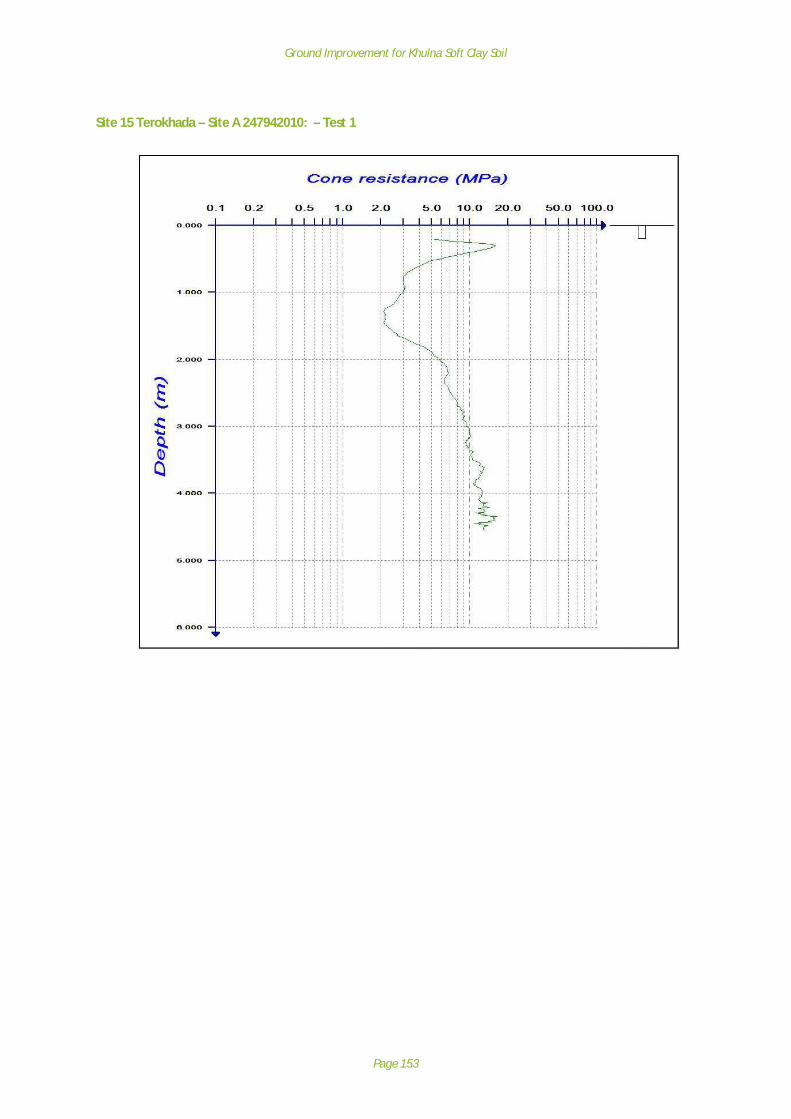
Ground Improvement for Khulna Soft Clay Soil
Page 153
Site 15 Terokhada – Site A 247942010: – Test 1

Ground Improvement for Khulna Soft Clay Soil
Page 154
Site 15 Terokhada – Site A 247942010: Test 2

Ground Improvement for Khulna Soft Clay Soil
Page 155
Site 13 Terokhada - B
Site 13 DescriptionSite 13 is a single lane carriageway with a flexible bituminous pavement. The carriageway isapproximately 3.6 m wide with a soft shoulder.
The embankment is constructed from organic clay at the bottom and silty clay at the top. The slopeswere recorded as significantly damaged and are vegetated with grasses, herbs and various species oftree. Some trees are leaning out from the slope whilst others are vertical. It is possible that the treesare tilting under their own self weight as the soft soil cannot support the root ball.
A canal has been created on the RHS of the road. Major erosion and damage has occurred to thehighway slope that runs into the canal. There is significant slope regression where material is fallinginto the canal and this regression has extended into the pavement at 2 locations forming twoconcave areas of pavement loss with each extending approximately 1m into road from the edge.
The local LGED Engineer reports that water levels come close to the pavement surface in the rainyseason.
Site 13 Investigation and testingInvestigation at the site comprised 3 No. trial pits and 3 No. Panda Probes. The site investigationlocations are detailed below:

Ground Improvement for Khulna Soft Clay Soil
Page 156
Site 13: Terokhada B
Summary of soil sampling for Site 13 Terokhada B
Site no. 13: Terokhada B (Road 247942003)
Trial Pit 1
Lithology:
Brown Silty Clay and plant roots.
N

Ground Improvement for Khulna Soft Clay Soil
Page 157
Trial Pit 2
Lithology:
Gray Silt with lenses of Clayey soil, plant roots andbrick fragments.
Trial Pit 3
Lithology: Brown Sandy Silt with plant root partlydecomposed wood fragments.
Summary of Laboratory Test Results for Site 13 Terokhada B
*Unified Soil Classification System
The samples retrieved from the 3 No. trial pits at Site 13 – Terokhada B, all had a differentclassification: Trial Pit 1 was a Lean Clay; Trial Pit 2 was a Fat Clay and Trial Pit 3 was a Silty Sand.
SiteNo.
TrialPit No.
SampleDepth(mbgl)
VisualClassification
USCS*Classification
LL (%) PL (%) SL (%) Ls (%) PI (%) MoistureContent(%)
OrganicContent
(%)
13 1. 0.3 ClayCL – Lean Clay
43 28 - - 17 17 -
2. 0.3 ClayCH - Fat Clay
47 21 11 28 26 26 4.5
3. 0.3 Fine SandSM – Silty Sand
- - - - - - -

Ground Improvement for Khulna Soft Clay Soil
Page 158
For the cohesive material, Liquid Limit ranged from 43% to 47%, Plastic Limit ranged from 21% to28% and Plasticity Index ranged from 17% to 26%. The Moisture Content ranged from 17% to 26%.One linear shrinkage test was conducted on the sample from TP2 and returned a value of 28%.
Summary of Panda Probe Results for Site 13 Terokhada B
PSD result for Sample 3, Site 13
SiteNumber
Site Name TestNumber
FinalDepth(mbgl)
EmbankmentHeight
(m)
Summary of Penetration
13 TerokhadaB
1 4.6 5.0 Slight reduction in soil strength below road surfacefrom 0.0 to 2.4 mbgl, before sharp, then steadyincrease to end of probe.
2 4.6 5.0 Reduction in soil strength below road surface from 0.0to 0.9 mbgl, before levelling off to 2.0m, then steadyincrease to end of probe.
3 4.6 5.0 General slight rise in soil strength to end of probe.

Ground Improvement for Khulna Soft Clay Soil
Page 159
Site 13 Terokhada – Site B 247942003: Test 1

Ground Improvement for Khulna Soft Clay Soil
Page 160
Site 13 Terokhada – Site B 247942003: Test 2

Ground Improvement for Khulna Soft Clay Soil
Page 161
Site 13 Terokhada – Site B 247942003: Test 3

Ground Improvement for Khulna Soft Clay Soil
Page 162
Site 21 Mongla A & B
Site 21: Road201582003

Ground Improvement for Khulna Soft Clay Soil
Page 163
Site 21 DescriptionSite 21 is a single lane carriageway with a flexible bituminous pavement. The carriageway isapproximately 3.6 m wide with soft shoulder. The road embankment is constructed from silty clay.The slopes were recorded during the inspection as being damaged. The slopes are vegetated withgrasses, herbs and trees of various species. There is minimal vegetation on water side of the roadand thick vegetation on landward side of the road.
The road surface is deformed along wheel tracks but more so on the water side of the carriageway.Associated with the deformation is the typical longitudinal cracking seen elsewhere. Patches ofblacktop loss are evident with the typical red colour that indicates the exposure and degradation ofthe underlying brick subbase.
The slope line is bulging out at a point that corresponds with a large patch of pavement loss. Theunsupported road side has slumped into the water, impacting on up to 0.3m of adjacent pavement.There is minimal vegetation along the water side.
There is a marked difference in level between the earthwork and bridge, indicative of differentialsettlement. There are significant cavities on the RHS of the single-track road where it meets thebridge, and material that has been lost under the bridge wing wall, where the wall has beenundermined. The earthwork slope and pile/board retaining structure is failing and moving towardswater, undermining the wing wall.
There is loss of slope material at the waterline; material has likely been washed-out by the drainagepipe that emanates from the embankment side. The slope has been cleared of trees and possiblydug into to facilitate the construction of stilted huts by locals
In many places there is embankment protection at the toe of the embankment in the form of 3mlong precast driven piles spaced at 0.9m centres, with vertical concrete boards bolted in a 2 pilearrangement. The piles are leaning out to differing degrees and the boards are misaligned.
The local LGED Engineer reports that water levels come close to the pavement surface in the rainyseason. There are culverts in the road embankment for cross drainage.
Site 21 Investigation and testingInvestigation at the site comprised 4 No. trial pits and 4 No. Panda Probes. The site investigationlocations are detailed below:

Ground Improvement for Khulna Soft Clay Soil
Page 164
Site 21: Mongla A & B
Summary of soil sampling for Site 21 Mongla A & B
Site no. 21: Mongla (Road 201582003)
Trial Pit 1
Lithology:
The soil sample composed of Sandy Clay wherethe Sand is Gray in colour, loosely compact. TheClay is also Gray in colour and shows moderateplasticity. The soil sample contains extensiveplant roots and reddish spots which may form bythe oxidation of soil.
N
Mongla A
Mongla B
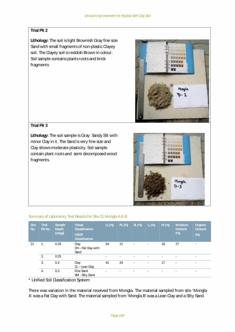
Ground Improvement for Khulna Soft Clay Soil
Page 165
Trial Pit 2
Lithology: The soil is light Brownish Gray fine sizeSand with small fragments of non-plastic Clayeysoil. The Clayey soil is reddish Brown in colour.Soil sample contains plants roots and brickfragments
Trial Pit 3
Lithology: The soil sample is Gray Sandy Silt withminor Clay in it. The Sand is very fine size andClay shows moderate plasticity. Soil samplecontain plant roots and semi decomposed woodfragments.
Summary of Laboratory Test Results for Site 21 Mongla A & B
* Unified Soil Classification System
There was variation in the material received from Mongla. The material sampled from site ‘MonglaA’ was a Fat Clay with Sand. The material sampled from ‘Mongla B’ was a Lean Clay and a Silty Sand.
SiteNo.
TrialPit No.
SampleDepth(mbgl)
VisualClassification
USCS*Classification
LL (%) PL (%) SL (%) Ls (%) PI (%) MoistureContent(%)
OrganicContent
(%)
21 1. 0.25 ClayCH – Fat Clay withSand
54 21 - - 33 27 -
2. 0.25 - - - - - - -
3. 0.3 ClayCL – Lean Clay
41 24 - - 17 - -
4. 0.3 Fine SandSM - Silty Sand
- - - - - - -

Ground Improvement for Khulna Soft Clay Soil
Page 166
For the cohesive soil taken from Trial Pit 1 and Trial Pit 3 the Liquid Limit ranged from 41% to 54%,the Plastic Limit ranged from 21% to 24% and the Plasticity Index ranged from 17% to 33%. TheMoisture Content for the sample from Trial Pit 1 was 27%.
Summary of Panda Probe Results for Site 21 Mongla A & B
PSD Result for Sample 4, Site 21
SiteNumber
SiteName
TestNumber
FinalDepth(mbgl)
EmbankmentHeight
(m)
Summary of Penetration
21 Mongla A& B
1 4.5 0.5 Reduction in soil strength below road surface from 0.1 to0.4 mbgl, before steady increase to 2.0 m then levels offto end of probe.
2 4.5 0.5 General slight rise in soil strength to end of probe.3 4.5 0.48 Reduction in soil strength below road surface from 0.2 to
0.7 mbgl, before increasing to 2.0m, then levelling off toend of probe
4 4.5 0.48 Reduction in soil strength below road surface from 0.2 to0.8 mbgl, before slight increase to end of probe

Ground Improvement for Khulna Soft Clay Soil
Page 167
Site 21 Mongla 201582003: Test 1

Ground Improvement for Khulna Soft Clay Soil
Page 168
Site 21 Mongla 201582003: Test 2

Ground Improvement for Khulna Soft Clay Soil
Page 169
Site 21 Mongla 201582003– Test 3

Ground Improvement for Khulna Soft Clay Soil
Page 170
Site 21 Mongla 201582003 – Test 4

Ground Improvement for Khulna Soft Clay Soil
Page 171
Appendix F: Ground Models
Site 3 Assasuni Observational Ground ModelThe site demonstrates loss of edge support, poor surface conditions, and over-steep slopes /erosion.
Key features Site photographErosion, over-steepening ofthe embankment slopes atSite 3
The embankment fill consists of Fat Clay material and generally has a cone resistance that reducesfrom the near surface layers to the base of the embankment illustrating probable poor compactionand consequently higher water content, leading to low strength and support characteristics. Littleself-weight compaction is likely due to the low height of the embankment, with only the nearsurface pavement layers (comprising higher quality material than the general embankment fill)demonstrating significant resistance to cone penetration.
The foundation soil sampled underlying the embankment consists of a Fat Clay. The cone resistancedoes show some local variability in resistance that is likely to the result of sandier or more organicmaterial. The foundation soil has been subject to loading from the embankment above and anincrease in resistance between 5 and 10 MPa from 1.0 to 2.5 mbgl may be the result of consolidationover time (although this cannot be confirmed). Beyond 3mbgl, there seems to be little increase incone resistance with depth. Notwithstanding the low load (1.2-1.5m high embankment), theanticipated deformation resulting is estimated as ~100mm of vertical deformation (see Section 6.3Analytical Ground Model) with the inherent impact on surface conditions.
Also, as the water level changes considerably at this location due to flooding and adjacent land use,inundation of the embankment fill will be significant and the Fat clay fill present will swell inresponse, and shrink as the material dries. This effect also contributes to the oversteep slopes andthe poor edge support that results from this.
The key contributory factors are illustrated below: -

Ground Improvement for Khulna Soft Clay Soil
Page 172
Table 12.2: Summary of key contributory factors (Site 3)
Features observed Key contributory factorspoor surface conditions vehicle overloading, embankment construction materials
and possibly methods, total settlement resulting fromfoundation soil consolidation and shrink/swell of the
embankment fill
over-steep slopes / erosion. Flooding and adjacent land use, together withshrink/swell of the embankment fill
Figure 12.1: Site 3 Assasuni Observational Ground Model

Ground Improvement for Khulna Soft Clay Soil
Page 173
Site 10 Dumuria A Observational Ground ModelSite 10 – Dumuria A was selected during the Field Situation Analysis to investigate the causes oflongitudinal cracking.
Key features Site photographLongitudinal crackingtowards the edge ofthe road pavement atSite 10
The main body of the embankment is composed of a Lean Clay and a Lean Clay with Sand. Thisplaced embankment fill material generally has a cone resistance of 2.5 to 9.5 MPa. Resistance withinthe embankment fill drops from the more competent near surface layers and then increases towardsthe base of the embankment fill and into the foundation soil. This illustrates probable poorcompaction of the fill material, leading to low strength and support characteristics.
The foundation soil has been subject to loading from the embankment above and an increase inresistance between 6 and 10 MPa from 2 mbgl is due to normal consolidation and the increasedoverburden resulting from the embankment over time (although the proportion of resistance thatcan be attributed to the embankment cannot be determined). The ~2m of fill (approx. 36kN/m2) isestimated to have resulted in ~150mm of vertical deformation (see Section 6.3 Analytical GroundModel) of the foundation soil, with the inherent impact on surface conditions, and could result in thecracking observed.
The longitudinal cracking is also likely to be as a result of embankment spreading, overloading thepalisade walls. The lateral load on the piled wall is not only applied through the embankment layers,but also the soft foundation soil consolidates and exerts a lateral load on to the supports, that onlyhave very limited embedment, and consequently rotate outwards.
The road use also contributes to the longitudinal cracking observed, with wheel track ruts evident.These are likely to be the result of inadequate pavement strength and embankment fill construction.
The key contributory factors are illustrated below: -Table 12.3: Summary of key contributory factors (Site 10)
Features observed Key contributory factorsLongitudinal cracking vehicle overloading, embankment construction materials and
possibly methods, total settlement resulting from foundationsoil consolidation, palisade walls offering little lateral
resistance to embankment fill and foundation soil spreading.
Deformed palisade walls Soft foundation soil has little resistance to the loads appliedto low embedment walls.
over-steep slopes / erosion. Flooding and adjacent land use, together with shrink/swell ofthe embankment fill
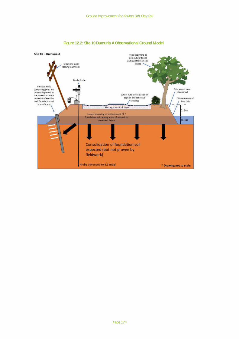
Ground Improvement for Khulna Soft Clay Soil
Page 174
Figure 12.2: Site 10 Dumuria A Observational Ground Model

Ground Improvement for Khulna Soft Clay Soil
Page 175
Site 11 Dumuria B Observational Ground ModelSite 11 – Dumuria B was selected for further investigation during the Field Situation Analysis due tothe observed spreading behaviour and poor road surface conditions.
Key features Site photographLateral spreading of theembankments at Site 11
The main body of the embankment is composed of a Fat Clay and a Fat Clay with Sand. This placedembankment fill material generally has a varying cone resistance of less 2 MPa to approximately 10MPa. There is a distinct reduction in strength (Test 2 and 3) below the pavement layers, before thisrecovers from 1mbgl. The Fat clay will experience volume change during wetting and drying, due tothe known changes in water levels that this site experiences during flooding.
The foundation soil consists of a Fat Clay and has a very consistent strength with depth,demonstrating a cone resistance of around 10 MPa from 1.5 to 2 mbgl to depth. Consolidation ofthe foundation soil is likely to have occurred due to the 1.6m of fill applied, and 120-130mm ofvertical deformation is likely to have resulted from the change in volume (see Section 6.3 AnalyticalGround Model).
The poor road surface conditions are predominantly due to pronounced lateral spreading of theembankment fill and consolidation of the underlying foundation soil. It is possible that bearingcapacity of the soil was exceeded at construction stage and continuing deformation has resulted,although due to the low height, this is unlikely.
The lateral spreading of the embankment material has resulted in a loss of material underlying andsupporting the pavement layers. Significant movement and deformation has occurred to theherringbone brick layer, leading to the degradation of the bricks. The deformation and degradationof the brick layer has resulted in pronounced reflective cracking in the asphalt and consequently,significant asphalt loss.
The key contributory factors are illustrated below: -
Table 12.4: Summary of key contributory factors (Site 11)
Features observed Key contributory factorsSpreading of embankment fill vehicle overloading, embankment construction materials
and possibly methods, total settlement resulting fromfoundation soil consolidation, shrink/swell during
inundation

Ground Improvement for Khulna Soft Clay Soil
Page 176
Figure 12.3: Site 11 Dumuria B Observational Ground Model

Ground Improvement for Khulna Soft Clay Soil
Page 177
Site 12 Rupsa Observational Ground ModelSite 12 – Rupsa was selected during the Field Situation Analysis to investigate the condition of thepalisade wall, bridge approaches and loss of edge support to the highway.
The embankment fill comprises Lean Clay and a Fat Clay. This placed embankment fill materialgenerally has a varying cone resistance (Test 2) reducing below the pavement layers from >20 MPadown to 2 MPa. This may reflect the varying repairs to the embankment where depressions havebeen filled with a mixture of crushed brick and soil.
The natural ground underlying the embankment consists of Lean Clay and Fat Clay and is anticipatedto have experienced consolidation over time (both normal consolidation and consolidation due toembankment loading), demonstrating a cone resistance of around 5 to 10 MPa from 1 to 2 mbgl todepth. Theoretical consolidation of the foundation soil due to the 1.5m of fill applied, is anticipatedto result in ~100mm of vertical deformation (see Section 6.3 Analytical Ground Model).
Longitudinal cracking was evident at Site 12 and has resulted from the development with time ofwheel track ruts. These are largely due to inadequate pavement design and construction, overloadedvehicles etc. It is highly likely that the herringbone brick subbase is pressing down into theunderlying embankment fill subgrade, leading to the creation of the wheel track ruts and resultantlongitudinal reflective cracking.
Lateral spreading was observed on at least one side of the embankment. This lateral spreading ofthe embankment material results in a loss of support to the pavement layers. The palisade wall atthe toe of the embankment offers little resistance to the lateral forces applied by the embankmentand consolidation of the foundation soil as embedment is very limited (3m).
The key contributory factors are illustrated below: -
Table 12.5: Summary of key contributory factors (Site 12)
Features observed Key contributory factorsSpreading of embankment fill vehicle overloading, embankment construction materials
and possibly methods, total settlement resulting fromfoundation soil consolidation, palisade walls offering littlelateral resistance to embankment fill and foundation soil
spreading
Deformed palisade walls Soft foundation soil has little resistance to the loadsapplied to low embedment walls.

Ground Improvement for Khulna Soft Clay Soil
Page 178
Figure 12.4: Site 12 – Rupsa Observational Ground Model

Ground Improvement for Khulna Soft Clay Soil
Page 179
Site 15 Terokhada A Observational Ground ModelSite 15 – Terokhada A was selected during the Field Situation analysis to investigate the poor roadsurface conditions, deformation of retaining wall and steep side-slopes.
The main body of the embankment is composed of a Lean Clay. This placed embankment fill materialgenerally has a cone resistance of 2.5 to 15 MPa, the higher values reflecting the influence of brokenbrick aggregate near the surface.
The natural ground tested underlying the embankment consists of a Lean Clay and is likely to haveexperienced consolidation as a result of the loading of embankment fill, approximately 40kN/m2. Thecone resistance starts to steadily rise from 2-3MPa at 1.5-2mbgl to around 10 MPa at 3 to 4mbgl.Theoretical vertical deformation of the foundation soil is estimated at between 180mm as a result ofthis loading. The bearing capacity of the foundation soil may have been exceeded duringconstruction (due to height of fill), and this may be the cause of the significant deformation noted onone side of the road. Even if the bearing capacity was not exceeded, the closer the loading to theultimate bearing capacity, the greater the degree of deformation experienced (see 6.3 AnalyticalGround Model).
Wheel track ruts were evident, and these are principally inadequate pavement design andconstruction for the vehicular usage.
As noted, Site 15 has higher embankment than the others observed, with steep side slopesexacerbating slope instability, particularly problematic during periods of inundation whenfloodwaters are high. Lean Clay may erode more readily due to higher silt content and cannotaccommodate changes in moisture content. Slope support in the form of palisade wall was presentbut this toe reinforcement was displaced and providing little resistance to slope movement.
The key contributory factors are illustrated in Table 12.6 and Figure 12.5 below: -
Table 12.6: Summary of key contributory factors (Site 15)
Features observed Key contributory factorspoor surface conditions vehicle overloading, embankment construction materials
and possibly methods, total settlement resulting fromfoundation soil consolidation – possible bearing capacityissues after construction has weakened foundation soils
over-steep slopes / erosion. Flooding and adjacent land use with already steep / highslopes. Lean materials erode and properties change
more readily than Fat clay during wetting/drying
Deformed palisade walls Soft foundation soil has little resistance to the loadsapplied to low embedment walls.

Ground Improvement for Khulna Soft Clay Soil
Page 180
Figure 12.5: Site 15 – Terokhada A Observational Ground Model

Ground Improvement for Khulna Soft Clay Soil
Page 181
Site 13 Terokhada B Observational Ground ModelSite 13 – Terokhada B was selected during the Field Situation Analysis to investigate the loss ofsupport / slope instability at highway edge.
The road embankment is constructed from Lean Clay and Fat Clay. This placed embankment fillmaterial generally has a cone resistance of 2.5 to 9.5 MPa, the higher values reflecting the influenceof broken brick aggregate near the surface. Test 3 revealed much softer embankment fill howeverwith cone resistance ranging between only 1 and 1.6 MPa.
The natural ground tested underlying the embankment consists of a Lean Clay and Fat Clay with acone resistance that starts to steadily rise from 2 to 2.5 mbgl to around 10 MPa. It is unlikely thatthe foundation soil is an influencing factor with the slope instability observed.
Two slope failures have occurred close to each other in the canal slope adjacent to the carriageway.The cause of the slope failures is due to the geometry of the slopes (over-steep), the materialsforming the slope and the water in the canal. Any fine soil material (clays and silts) cut at the slopeangle present at the site would be unstable in the long term. Changes (increase) in water levels inthe canal influence pore water pressure in the slope, leading to reduced strength, which isparticularly problematic as water levels recede after inundation (rapid drawdown). Slope failures(within the embankment fill) would often result in steep slopes exposed to fluctuating water levels.
The key contributory factors are illustrated below: -
Table 12.7: Summary of key contributory factors (Site 13)
Features observed Key contributory factorsSlope instability through embankment The presence of the canal and geometry is the key
factor. Fluctuating water levels and adjacent land usewith steep / high slopes.
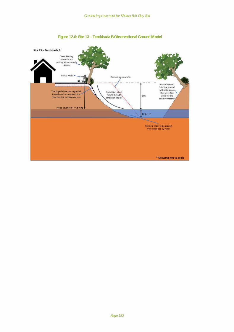
Ground Improvement for Khulna Soft Clay Soil
Page 182
Figure 12.6: Site 13 – Terokhada B Observational Ground Model

Ground Improvement for Khulna Soft Clay Soil
Page 183
Site 21 Mongla A & B Observational Ground ModelSite 21 – Mongla A & B was selected during the Field Situation analysis to be investigated for bridgeapproach, differential settlement and retaining wall supports.
Key features Site photographDifferential settlement and erosionadjacent to structure at Mongla B - Site 21.
The road embankment is constructed predominantly from Lean Clay and Fat Clay with Sand.At Mongla A - the placed embankment fill material generally has a cone resistance of 1.5 to 4 MPa.At Mongla B - the placed embankment fill material generally has a cone resistance of 20 MPa nearthe surface, dropping to around 4 MPa, the higher values reflecting the influence of broken brickaggregate near the surface.
The natural ground underlying the embankment consists of a Lean Clay and Fat Clay with Sand anddemonstrates a cone resistance that starts to steadily rise from 4 MPa at 1 – 2 mbgl to > 10 MPa at4.5 mbgl.
The level of the approach embankment has dropped relative to the abutment and concrete bridgedeck leaving a pronounced step. This is the result of consolidation of the underlying foundation soiland embankment materials. Differential movement in the order of 200-250mm would be expected.The step has likely been addressed on multiple occasions and further loss of level through erosionand use has occurred. Bearing capacity of the foundation soil could have been an issue duringconstruction, due to the higher level of embankment, although this mechanism cannot be confirmedat this location.
Damage to the bridge structure has been caused by river scour severely undermining the wing-walls,leading to an ensuing loss of fill from behind the wall – this has led to a further drop in the level ofthe approach embankment fill, located behind the wing walls, relative to the bridge deck.
It is clear, that the embankment slopes are steeper than the internal angle of friction of the fillmaterial can accommodate. Typically, slopes in excess of 1:2(v:h) would be marginally stable whenconstructed from Lean or Fat Clay, and with the addition of water, instability would be anticipated.The slope angles presented in LGED (1999) Road Pavement Design Manual provide indicative safeslope angles for different earthworks materials, and whether dry or wet.
The reinforcement that has been provided in places at the slope toe is insufficient and has beendisplaced. The loads translated onto the walls cannot be sustained by the low foundation soilstrength (at shallow depth) and limited depth of embedment of the wall.

Ground Improvement for Khulna Soft Clay Soil
Page 184
The key contributory factors are illustrated in Table 12.8 and Figure 12.7 below: -
Table 12.8: Summary of key contributory factors (Site 21)
Features observed Key contributory factorsStep between bridge and approach embankment Differential settlement between the stiff bridge
foundation support and the foundation soil below theapproach embankment. Erosion below the wing walls
and construction materials / methods.
Deformed palisade walls Soft foundation soil has little resistance to the loadsapplied to low embedment walls.
Figure 12.7: Site 21 - Mongla Observational Ground Model

Ground Improvement for Khulna Soft Clay Soil
Page 185
Appendix G: Compendium of photographs
Site 3: Assasuni
Photo: Site 3, Test Pit 1 Photo: Site 3, Test Pit 2
Photo: Site 3, Test Pit 3 Photo: LGED Upazila Engr. assisting in samplecollection

Ground Improvement for Khulna Soft Clay Soil
Page 186
Site 10: Dumuria A
Photo: Site 10, Test Pit 1 Photo: Site 10, Test Pit 2
Photo: Site 10, Test Pit 3

Ground Improvement for Khulna Soft Clay Soil
Page 187
Site 11: Dumuria B
Photo: Site 11, Test Pit 1 Photo: Site 11, Test Pit 2
Site 12: Rupsa
Photo: Site 12, Test Pit 1 Photo: Site 12, Test Pit 2
Photo: Site 12, Sample collection

Ground Improvement for Khulna Soft Clay Soil
Page 188
Site 15: Terokhada A
Photo: Site 15, Structure inspection Photo: Site 15, Test Pit 2
Site 13: Terokhada B
Photo: Site 13, Test Pit 1 Photo: Site 13, Test Pit 2

Ground Improvement for Khulna Soft Clay Soil
Page 189
Site 21: Mongla
Photo: Site 21, Structure Inspection Photo: Site 21, Test Pit 1
Photo: Site 21, Test Pit 3

Ground Improvement for Khulna Soft Clay Soil
Page 190
Appendix H: Example Geotechnical Risk RegisterTable 12.13 is an example Geotechnical Risk Register. The risks associated with other aspects of ascheme, such as procedures, highway design and contractual and strategic issues are not dealt withhere and the scheme risk register should be prepared for information on these elements.
The Geotechnical Risk Register should be considered as a live document and updated throughoutthe course of the scheme. It is incumbent on all parties involved in the scheme to advise the othermembers when the risks change.
Various threats are identified and the potential consequences of these occurring are described. Therisk assessment is qualitative and the various threat are assessed using the following criteria:
· Cost;· Programme;· Health and Safety; and,· Environment.
The risk is derived by considering the impact and likelihood for each threat and opportunity. Boththe impact and likelihood have been assessed using a scale of 1 to 5, corresponding to “very low” to“very high” for impact and “negligible / improbable” to “very likely / almost certain” for likelihood.These ratings are summarised in Table 12.9 and Table 12.10.Table 12.9: Hazard Impact Table
Impact Cost Programme Healthand Safety
Environment
1 Very Low Negligible Negligible Negligible effecton programme
Negligible Negligible
2 Low Significant 1% Budget 5% effect onprogramme
Minor injury Minor environmentalincident
3 Medium Serious 10% Budget 12% effect onprogramme
Major injury Environmentalincident requiringmanagement input
4 High Threat to future workand Client relations
20% Budget 25% effect onprogramme
Fatality Environmentalincident leading toprosecution orprotestor action
5 Very High Threat to businesssurvival and credibility
50% Budget 50% effect onprogramme
Multiplefatalities
Major environmentalincident withirreversible effectsand threat to publichealth or protectednatural resource
Table 12.10: Hazard Likelihood Index
Likelihood Probability1 Negligible / Improbable < 1%
2 Unlikely / Remote > 1%
3 Likely / Possible > 10%
4 Probable > 50%
5 Very Likely / Almost Certain > 90%
The risk score is calculated by multiplying the impact score by the likelihood score, giving the scoresshown in Table 12.11.
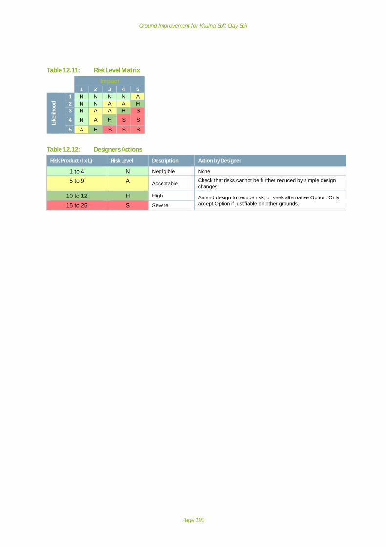
Ground Improvement for Khulna Soft Clay Soil
Page 191
Table 12.11: Risk Level Matrix
Impact1 2 3 4 5
Like
lihoo
d
1 N N N N A2 N N A A H3 N A A H S
4 N A H S S
5 A H S S S
Table 12.12: Designers Actions
Risk Product (I x L) Risk Level Description Action by Designer
1 to 4 N Negligible None
5 to 9 A Acceptable Check that risks cannot be further reduced by simple designchanges
10 to 12 H High Amend design to reduce risk, or seek alternative Option. Onlyaccept Option if justifiable on other grounds.15 to 25 S Severe
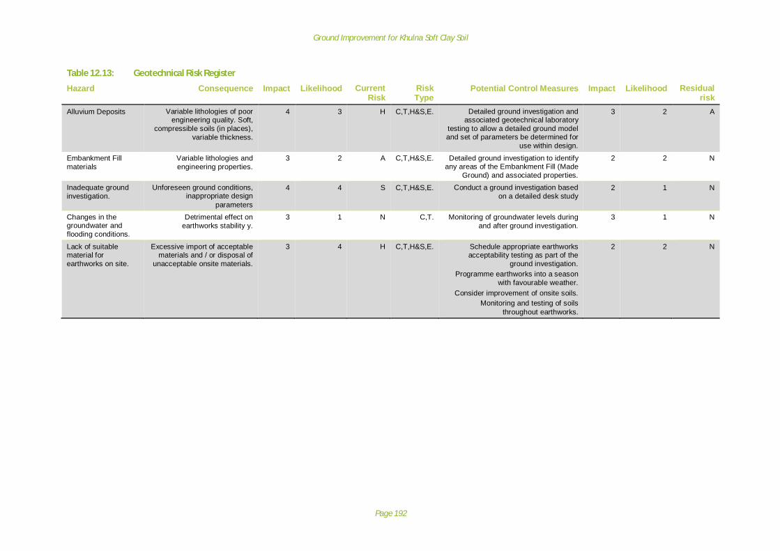
Ground Improvement for Khulna Soft Clay Soil
Page 192
Table 12.13: Geotechnical Risk Register
Hazard Consequence Impact Likelihood CurrentRisk
RiskType
Potential Control Measures Impact Likelihood Residualrisk
Alluvium Deposits Variable lithologies of poorengineering quality. Soft,
compressible soils (in places),variable thickness.
4 3 H C,T,H&S,E. Detailed ground investigation andassociated geotechnical laboratory
testing to allow a detailed ground modeland set of parameters be determined for
use within design.
3 2 A
Embankment Fillmaterials
Variable lithologies andengineering properties.
3 2 A C,T,H&S,E. Detailed ground investigation to identifyany areas of the Embankment Fill (Made
Ground) and associated properties.
2 2 N
Inadequate groundinvestigation.
Unforeseen ground conditions,inappropriate design
parameters
4 4 S C,T,H&S,E. Conduct a ground investigation basedon a detailed desk study
2 1 N
Changes in thegroundwater andflooding conditions.
Detrimental effect onearthworks stability y.
3 1 N C,T. Monitoring of groundwater levels duringand after ground investigation.
3 1 N
Lack of suitablematerial forearthworks on site.
Excessive import of acceptablematerials and / or disposal of
unacceptable onsite materials.
3 4 H C,T,H&S,E. Schedule appropriate earthworksacceptability testing as part of the
ground investigation.Programme earthworks into a season
with favourable weather.Consider improvement of onsite soils.
Monitoring and testing of soilsthroughout earthworks.
2 2 N

Ground Improvement for Khulna Soft Clay Soil
Page 193
Appendix I: International Ground Improvement TechniquesAs stated in the CIRIA C573: A Guide to Ground Treatment, virtually all engineering constructioninvolves the ground. When constructing in poor ground conditions, there are five available options:
· To bypass the poor ground, by moving to a new site, or using deep foundations to strongerground.
· To remove the poor ground, replacing it with better material.· To design the structure to allow for the behaviour of the poor ground under load.· To treat the poor ground to improve its properties (i.e. ground improvement).· To abandon the project (the promoter’s decision).
The fourth option, of ground treatment, gives considerable scope to engineers for finding a viablesolution to the problems of poor ground. A wide range of treatments are available, techniques canbe selected and combined to cope with different aspects of the poor ground, and there is increasingconfidence both in what can be achieved by well executed treatment and in its proper integrationinto the overall scheme for the construction. All these points are evidence of how valuable thisoption is.
The objective of treatment is of course improvement. When ground treatment is being consideredas an option, it is important that all who will be involved in it should recognise not only what canreasonably be achieved by a particular technique, but also the extent of their responsibility if it ischosen.
The term “ground improvement” is open to different interpretations. First, it is an intention orobjective, not the process of achieving it, although the term is often used in that sense. Second,improvement is a relative condition as to which aspect and to what degree there is improvement.
Ground treatment techniques have been in use around the world for many centuries but havedeveloped greatly over the past 40 years.
CIRIA C573: A Guide to Ground Treatment states that: ‘In the United Kingdom, some 75 per cent ofthe ground improvement contracts using the techniques of vibro-replacement and dynamiccompaction are for man-made ground. These two techniques, including their application to loose orsoft natural soils, are probably the commonest type of ground treatment used in the UK. Foroverseas work, the proportions of specialist ground treatments are reversed, i.e. 30 percent are forman-made ground and 70 per cent for natural ground’.
The techniques of ground improvement used around the world have been grouped into 8 No. broadcategories:
· Improvement by vibration:o Vibro-compaction;o Vibro-replacement;o Dynamic compaction;o Vibratory probing;o Compaction piles;o Blasting;
· Improvement by adding load (or increasing the effective stresses):o Pre-compression;o Vertical drains;o Inundation;o Vacuum preloading;

Ground Improvement for Khulna Soft Clay Soil
Page 194
o Dewatering fine soils;o Pressure berms.
· Improvement by structural reinforcement:o Reinforced soil;o Soil nailing;o Root and micro-piles;o Slope dowels;o Embankment piles;
· Improvement by structural fill:o Remove and replacement;o Displacement;o Reduced load;
· Improvement by admixtures:o Lime / cement columns;o Mix-in-place by single augur;o Lime stabilisation of slopes;o Stabilisations of subgrades;
· Improvement by grouting:o Permeation;o Hydro-fracture;o Jet grouting;o Compaction grouting;o Cavity filling.
· Improvement by thermal stabilisation.o Freezing.o Heating.
· Improvement by vegetation.o Vegetation planting.
NB: Although the above headings for the groups of methods reflect what is being undertaken to theground to improve it, they do not characterise the way the ground is to be improved, nor do theyshow the purpose of the improvement. Many of the techniques can be used for different purposesand by enhancing one aspect of soil behaviour other aspects are also improved.
In accordance with the breakdown of each category in CIRIA C573, we can define simply, the generalmethod by which the ground is improved for each of the eight abovementioned groundimprovement categories:
Improvement by vibration:
Vibration can be used to compact soils and fills. The densification is achieved by a combination ofground displacement and vibration, in most cases with the addition of new material into the ground.
Improvement by adding load (or increasing the effective stresses).
Increasing the load on the ground causes it to compress. How much compression and how long ittakes to happen depends on the arrangement of the ground particles, on the degree of saturation,and on how freely the soil can drain. For loose and particularly unsaturated fills, adding load inducesrapid settlement; soft, saturated clays, on the other hand, take months or years to consolidate underan added load while pore pressures dissipate and the effective stress in the soil increases. Theimprovement techniques of adding load fall into two, not necessarily exclusive categories:

Ground Improvement for Khulna Soft Clay Soil
Page 195
· Where the improvement largely comes about by the increase in total stress· Where the improvement depends upon the increase in effective stress and the technique
encourages or accelerates that.
Improvement by structural reinforcement.
Many ground improvement techniques could be considered as a form of reinforcement. Stonecolumns, for example, are introduced materials that stiffen the ground; some grouts strengthen themass of soil into which they are injected. The distinction drawn for the classification used in thisreport of structural reinforcement is that prefabricated tensile or shear elements are installed in theground with the purpose of forming a composite material.
Improvement by structural fill.
The principle of ground improvement by structural fill is to replace a weak soil with a better one.Another, more recent option is to use lightweight materials instead of heavier earth fills above weakground. These options include:
· Displacement.· Reducing load.· Removal and replacement.
Improvement by admixtures.
The use of admixtures, such as lime, cement, oils and bitumens, and even sulphur, is one of theoldest and most widespread methods of improving a soil. Usually the purpose is to strengthen alocally available earth fill to construct a low-cost road base, e.g. cement stabilised soil or soil-cement, or to mix lime into highly plastic clays. Plant was developed either to mix the stabiliser inplace, i.e. to strengthen foundation soils or layers of the fill, or for central mixing to which the soil istransported.
Improvement by grouting.
A general definition of grouting for ground improvement is: “the controlled injection of material,usually in a fluid phase, into soil or rock in order to improve the physical characteristics of theground”. Such a definition does not cover all types or purposes of grouting in the ground, e.g.grouting to raise ground slabs or road pavements, but it does cover grouting to fill voids in theground, whether natural (such as in karstic limestone) or resulting from human activity.
Improvement by thermal stabilisation.
Even in the temperate UK, everyone is familiar with the way that surface soils are hardened, albeittemporarily, by frost and hot, dry weather. The removal of heat from the soil turning its pore waterinto ice is a very powerful technique rendering the ground impermeable and, for unconsolidatedmaterials, making them stronger. Applying heat to clays to drive out free pore water and, at highertemperatures, the water adsorbed on particle surfaces, creates a very hard, durable material - ineffect, the same methods as when making brick or mud (adobe) building blocks. Ground freezing is along established and particularly effective method of ground stabilisation for temporary works.Ground heating is rare, but when it has been used its purpose was longer-term improvement.
Improvement by vegetation.Vegetation as ground improvement is the biological reinforcement of ground by plant roots to retainearth masses and prevent soil loss.

Ground Improvement for Khulna Soft Clay Soil
Page 196
Appendix J: Ground Improvement Techniques for Rural Roads in Bangladesh
The following Table presents the list of all ground improvement techniques available (as perAppendix I), those that are used in Bangladesh and the techniques considered applicable for use onrural road infrastructure.Table 12.14: Ground improvement techniques for rural roads in Bangladesh
Ground ImprovementCategory
Technique In common use inBangladesh
Applicable for useon Rural Roads
Improvement by vibration: Vibro-compaction;
Vibro-replacement;
Dynamic compaction; Y unlikely
Vibratory probing;
Compaction piles; Y Y
Blasting;
Improvement by adding load(or increasing the effectivestresses):
Pre-compression; Y Y
Vertical drains; Y Y
Inundation;
Vacuum preloading;
Dewatering fine soils;
Pressure berms.
Improvement by structuralreinforcement:
Reinforced soil; Y
Soil nailing;
Root and micro-piles;
Slope dowels;
Embankment piles;
Improvement by structural fill: Remove and replacement; Y Y
Displacement; Y Y
Reduced load;
Improvement by admixtures: Lime / cement columns; Y
Mix-in-place by single augur; Y
Lime stabilisation of slopes;
Stabilisations of subgrades; Y
Improvement by grouting: Permeation;
Hydro-fracture;
Jet grouting; Y unlikely
Compaction grouting;
Cavity filling.
Improvement by thermalstabilisation.
Freezing.
Heating.
Improvement by vegetation. Vegetation planting.
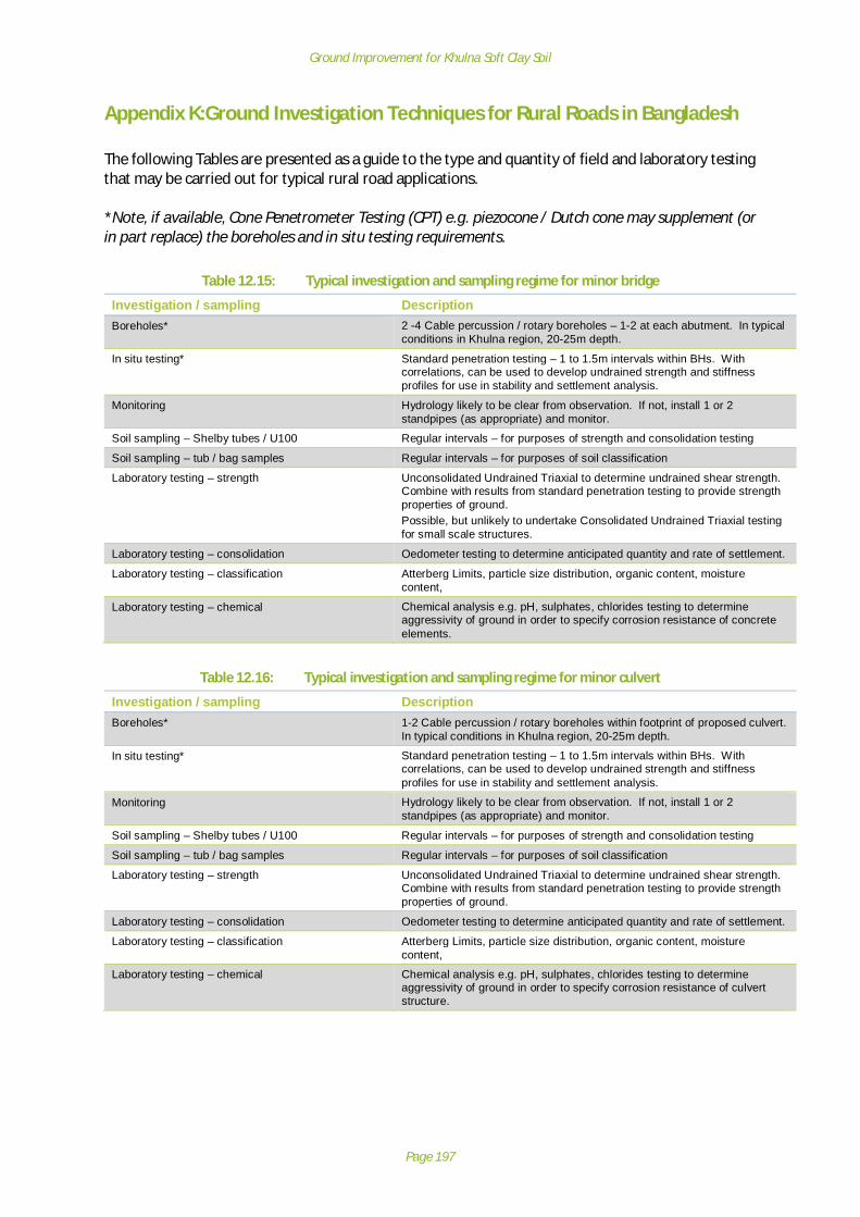
Ground Improvement for Khulna Soft Clay Soil
Page 197
Appendix K:Ground Investigation Techniques for Rural Roads in Bangladesh
The following Tables are presented as a guide to the type and quantity of field and laboratory testingthat may be carried out for typical rural road applications.
*Note, if available, Cone Penetrometer Testing (CPT) e.g. piezocone / Dutch cone may supplement (orin part replace) the boreholes and in situ testing requirements.
Table 12.15: Typical investigation and sampling regime for minor bridge
Investigation / sampling DescriptionBoreholes* 2 -4 Cable percussion / rotary boreholes – 1-2 at each abutment. In typical
conditions in Khulna region, 20-25m depth.
In situ testing* Standard penetration testing – 1 to 1.5m intervals within BHs. Withcorrelations, can be used to develop undrained strength and stiffnessprofiles for use in stability and settlement analysis.
Monitoring Hydrology likely to be clear from observation. If not, install 1 or 2standpipes (as appropriate) and monitor.
Soil sampling – Shelby tubes / U100 Regular intervals – for purposes of strength and consolidation testing
Soil sampling – tub / bag samples Regular intervals – for purposes of soil classification
Laboratory testing – strength Unconsolidated Undrained Triaxial to determine undrained shear strength.Combine with results from standard penetration testing to provide strengthproperties of ground.Possible, but unlikely to undertake Consolidated Undrained Triaxial testingfor small scale structures.
Laboratory testing – consolidation Oedometer testing to determine anticipated quantity and rate of settlement.
Laboratory testing – classification Atterberg Limits, particle size distribution, organic content, moisturecontent,
Laboratory testing – chemical Chemical analysis e.g. pH, sulphates, chlorides testing to determineaggressivity of ground in order to specify corrosion resistance of concreteelements.
Table 12.16: Typical investigation and sampling regime for minor culvert
Investigation / sampling DescriptionBoreholes* 1-2 Cable percussion / rotary boreholes within footprint of proposed culvert.
In typical conditions in Khulna region, 20-25m depth.
In situ testing* Standard penetration testing – 1 to 1.5m intervals within BHs. Withcorrelations, can be used to develop undrained strength and stiffnessprofiles for use in stability and settlement analysis.
Monitoring Hydrology likely to be clear from observation. If not, install 1 or 2standpipes (as appropriate) and monitor.
Soil sampling – Shelby tubes / U100 Regular intervals – for purposes of strength and consolidation testing
Soil sampling – tub / bag samples Regular intervals – for purposes of soil classification
Laboratory testing – strength Unconsolidated Undrained Triaxial to determine undrained shear strength.Combine with results from standard penetration testing to provide strengthproperties of ground.
Laboratory testing – consolidation Oedometer testing to determine anticipated quantity and rate of settlement.
Laboratory testing – classification Atterberg Limits, particle size distribution, organic content, moisturecontent,
Laboratory testing – chemical Chemical analysis e.g. pH, sulphates, chlorides testing to determineaggressivity of ground in order to specify corrosion resistance of culvertstructure.

Ground Improvement for Khulna Soft Clay Soil
Page 198
Table 12.17: Typical investigation and sampling regime for approach embankments
Investigation / sampling DescriptionBoreholes* 2 -4 Cable percussion / rotary boreholes. 1-2 for each approach
embankment depending on scale. In typical conditions in Khulna region,20-25m depth.
In situ testing* Standard penetration testing – 1 to 1.5m intervals within BHs. Withcorrelations, can be used to develop undrained strength and stiffnessprofiles for use in stability and settlement analysis.
Trial Pits Specify in borrow areas to characterise the fill materials. Only necessary ifembankment fill to be recovered from adjacent to proposed alignment
Soil sampling – Shelby tubes / U100 Regular intervals – for purposes of strength and consolidation testing
Soil sampling – tub / bag samples Regular intervals – for purposes of soil classification
Laboratory testing – consolidation Unconsolidated Undrained Triaxial to determine undrained shear strength.Combine with results from standard penetration testing to provide strengthproperties of ground.
Laboratory testing – strength Oedometer testing to determine anticipated quantity and rate of settlement.
Laboratory testing – classification Atterberg Limits, particle size distribution, organic content, moisturecontent,
Laboratory testing – chemical If structures present only. Chemical analysis e.g. pH, sulphates, chloridestesting to determine aggressivity of ground in order to specify corrosionresistance of structures where present e.g. palisade toe walls, gabions.
Laboratory testing – other Compaction type testing on material from borrow areas; including optimummoisture content, maximum dry density, laboratory CBR.
Table 12.18: Typical investigation and sampling regime for general embankments
Investigation / sampling DescriptionBoreholes* 1 Cable percussion / rotary boreholes through embankments at 50-100m
spacing along alignment. In typical conditions in Khulna region, ideally 20-25m depth, but could reduce depth or increase spacing if necessary.
In situ testing * Standard penetration testing – 1 to 1.5m intervals within BHs. Withcorrelations, can be used to develop undrained strength and stiffnessprofiles for use in stability and settlement analysis.
Trial Pits Specify in borrow areas to characterise the fill materials. Only necessary ifembankment fill to be recovered from adjacent to proposed alignment
Soil sampling – Shelby tubes / U100 Regular intervals – for purposes of strength and consolidation testing
Soil sampling – tub / bag samples Regular intervals – for purposes of soil classification
Laboratory testing – consolidation Unconsolidated Undrained Triaxial to determine undrained shear strength.Unlikely to undertake Consolidated Undrained Triaxial testing for smallscale structures.
Laboratory testing – strength Oedometer may be undertaken to determine anticipated quantity and rateof settlement.
Laboratory testing – classification Atterberg Limits, particle size distribution, organic content, moisturecontent,
Laboratory testing – chemical If structures present only. Chemical analysis e.g. pH, sulphates, chloridestesting to determine aggressivity of ground in order to specify corrosionresistance of structures where present e.g. palisade toe walls, gabions.
Laboratory testing – other Compaction type testing on material from borrow areas; including optimummoisture content, maximum dry density, laboratory CBR.

Ground Improvement for Khulna Soft Clay Soil
Page 199