Grooving Tool Holders GND Type Expansion - … · GNDL R2525M 220 GCM N2002 GG ... CG Type RG Type...
14
P M KN SH TOOLING NEWS E-112 Grooving Tool Holders GND Type 6 Types of Chipbreakers Expansion
-
Upload
truongdien -
Category
Documents
-
view
222 -
download
0
Transcript of Grooving Tool Holders GND Type Expansion - … · GNDL R2525M 220 GCM N2002 GG ... CG Type RG Type...

P M K N S HTOOLING NEWS E-112
Grooving Tool HoldersGND Type
6 Types ofChipbreakers
Expansion
2
2 3 4 5 6 7 8
3
4 5 6 7 8
3
4 5
6
2 3
4 5 6 7 8
2 3
4 5 6
3
3
4
4 5 6
2 3 4 5
2 3 4 5
3 4 5 6
Work Material:Holder:Insert:Cutting Conditions:
15CrMo5GNDL R2525M 220GCM N2002 GGvc=100m/min, f=0,1mm/rev, ap=20mm, wet
Eliminates Vibration
Single-Piece Construction
Special Steel
GND Type Conventional Tool
Vibr
atio
n lo
w
Vibr
atio
n st
rong
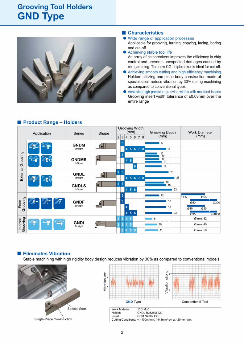
Characteristics
Applicable for grooving, turning, copying, facing, boring and cut-off.
Wide range of application processes
Achieving stable tool lifeAn array of chipbreakers improves the efficiency in chip control and prevents unexpected damages caused by chip jamming. The new CG-chipbreaker is ideal for cut-off.Achieving smooth cutting and high efficiency machiningHolders utilizing one-piece body construction made of special steel, reduce vibration by 30% during machining as compared to conventional types.Achieving high precision grooving widths with moulded insertsGrooving insert width tolerance of ±0,03mm over the entire range
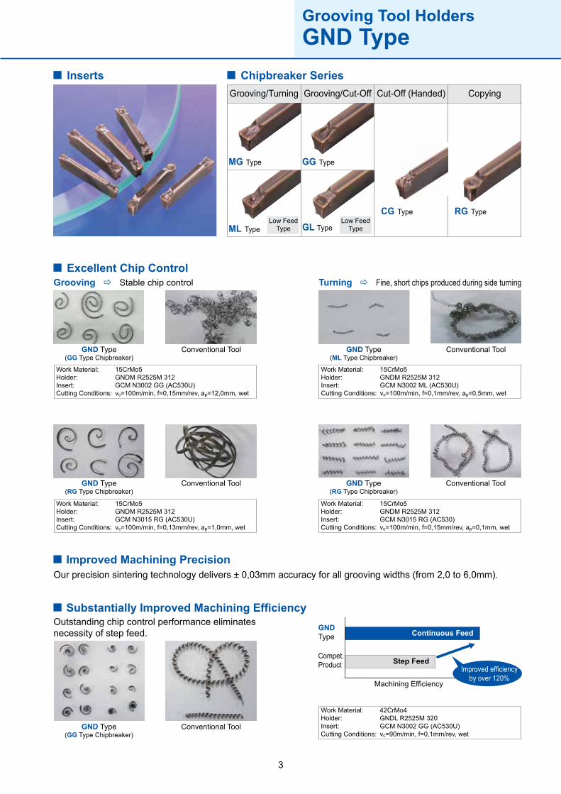
GNDMStraight
GNDMSL-Style
GNDLStraight
GNDFStraight
GNDIStraight
GNDLSL-Style
12
18101212
1414
20
2516
1823
12
18
18
23
6
10
11
Ø min. 32
Ø min. 40
Ø min. 50
Ø35 Ø55
Ø50 Ø300
Ø40 Ø55
Ø35 Ø1000
Application Series ShapeGrooving Width
(mm) Grooving Depth(mm)
Work Diameter(mm)
Ext
erna
l Gro
ovin
gFa
ce
Gro
ovin
gIn
tern
al
Gro
ovin
g
Product Range – Holders
Stable machining with high rigidity body design reduces vibration by 30% as compared to conventional models.
Grooving Tool HoldersGND Type
3
MG Type GG Type
ML Type GL Type
CG Type RG Type
Grooving/Turning Grooving/Cut-Off Cut-Off (Handed) Copying
Inserts
Excellent Chip Control
GND Type(GG Type Chipbreaker)
Conventional Tool
Work Material:Holder:Insert:Cutting Conditions:
15CrMo5GNDM R2525M 312GCM N3002 GG (AC530U)vc=100m/min, f=0,15mm/rev, ap=12,0mm, wet
Work Material:Holder:Insert:Cutting Conditions:
15CrMo5GNDM R2525M 312GCM N3002 ML (AC530U)vc=100m/min, f=0,1mm/rev, ap=0,5mm, wet
Work Material:Holder:Insert:Cutting Conditions:
15CrMo5GNDM R2525M 312GCM N3015 RG (AC530U)vc=100m/min, f=0,13mm/rev, ap=1,0mm, wet
Work Material:Holder:Insert:Cutting Conditions:
15CrMo5GNDM R2525M 312GCM N3015 RG (AC530)vc=100m/min, f=0,15mm/rev, ap=0,1mm, wet
GND Type(ML Type Chipbreaker)
Conventional Tool
GND Type(RG Type Chipbreaker)
Conventional Tool GND Type(RG Type Chipbreaker)
Conventional Tool
Grooving Stable chip control Turning Fine, short chips produced during side turning
Improved Machining PrecisionOur precision sintering technology delivers ± 0,03mm accuracy for all grooving widths (from 2,0 to 6,0mm).
GND Type(GG Type Chipbreaker)
Conventional Tool
Substantially Improved Machining EfficiencyOutstanding chip control performance eliminates necessity of step feed.
Work Material:Holder:Insert:Cutting Conditions:
42CrMo4GNDL R2525M 320GCM N3002 GG (AC530U)vc=90m/min, f=0,1mm/rev, wet
Continuous Feed
Step FeedImproved efficiency
by over 120%
GNDType
Compet.Product
Machining Efficiency
Low Feed Type
Grooving Tool HoldersGND Type
Chipbreaker Series
Low Feed Type
4
MG ML GG GL CG RG
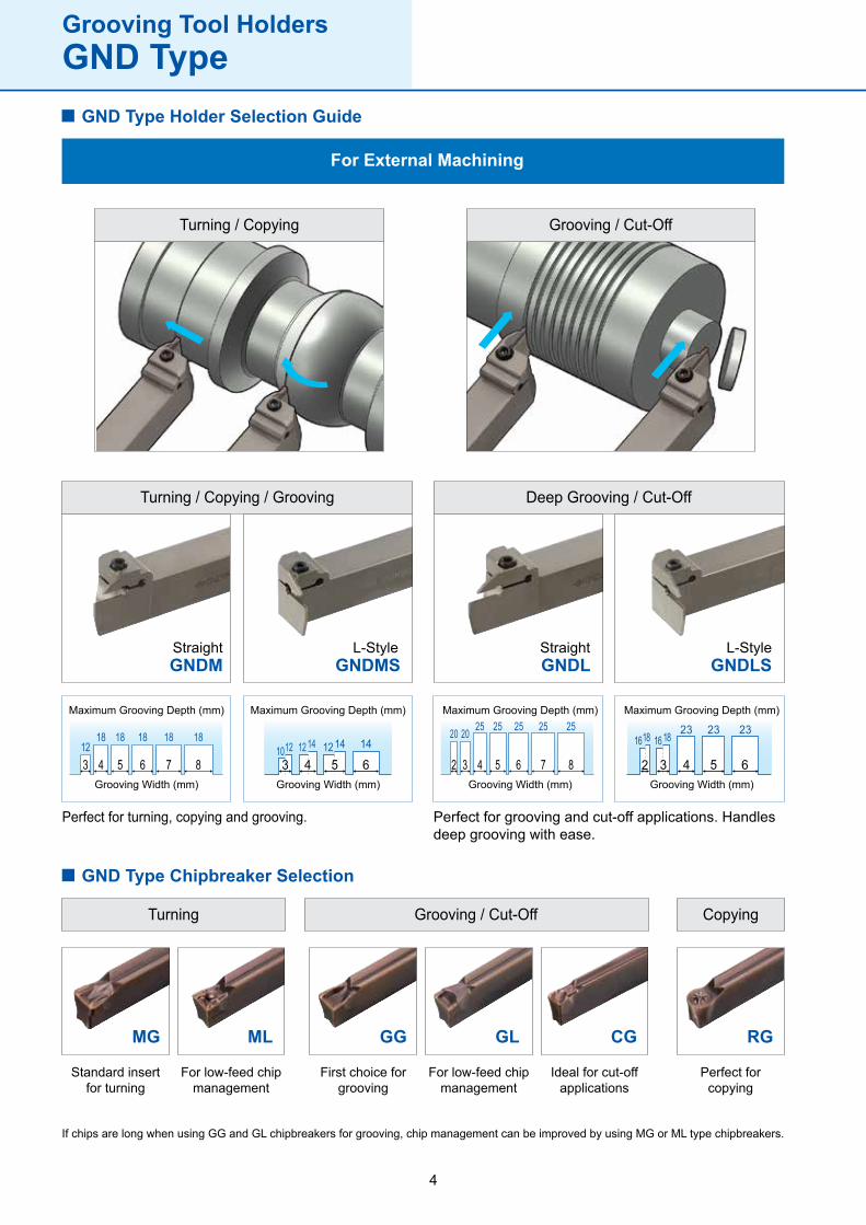
GND Type Holder Selection Guide
For External Machining
Standard insertfor turning
For low-feed chip management
First choice forgrooving
For low-feed chip management
Ideal for cut-off applications
Perfect forcopying
Turning Grooving / Cut-Off Copying
Turning / Copying Grooving / Cut-Off
StraightGNDM
L-StyleGNDMS
StraightGNDL
L-StyleGNDLS
Turning / Copying / Grooving Deep Grooving / Cut-Off
Maximum Grooving Depth (mm) Maximum Grooving Depth (mm) Maximum Grooving Depth (mm) Maximum Grooving Depth (mm)
Grooving Width (mm) Grooving Width (mm) Grooving Width (mm) Grooving Width (mm)
Grooving Tool HoldersGND Type
Perfect for turning, copying and grooving. Perfect for grooving and cut-off applications. Handles deep grooving with ease.
If chips are long when using GG and GL chipbreakers for grooving, chip management can be improved by using MG or ML type chipbreakers.
GND Type Chipbreaker Selection
5
MG ML GG GL RG
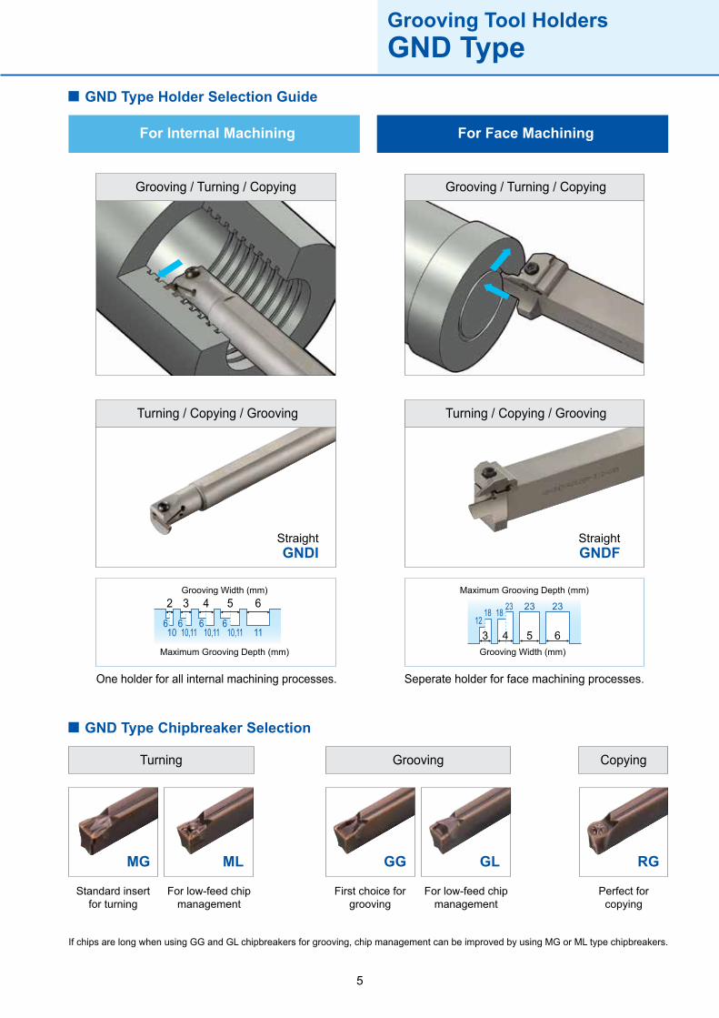
For Internal Machining For Face Machining
Perfect forcopying
First choice forgrooving
For low-feed chip management
Standard insertfor turning
For low-feed chip management
Turning Grooving Copying
GND Type Holder Selection Guide
Grooving / Turning / Copying Grooving / Turning / Copying
StraightGNDI
StraightGNDF
Turning / Copying / Grooving Turning / Copying / Grooving
Maximum Grooving Depth (mm)
Grooving Width (mm) Maximum Grooving Depth (mm)
Grooving Width (mm)
Grooving Tool HoldersGND Type
One holder for all internal machining processes. Seperate holder for face machining processes.
If chips are long when using GG and GL chipbreakers for grooving, chip management can be improved by using MG or ML type chipbreakers.
GND Type Chipbreaker Selection
6
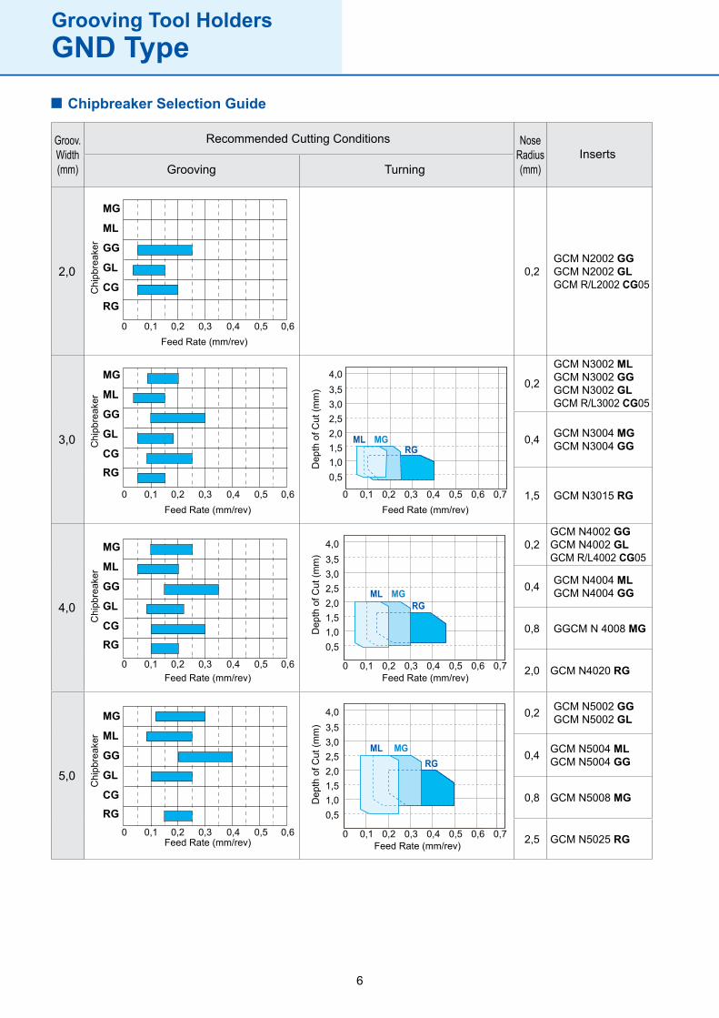
2,0 0,2GCM N2002 GGGCM N2002 GLGCM R/L2002 CG05
3,0
0,2
GCM N3002 MLGCM N3002 GGGCM N3002 GLGCM R/L3002 CG05
0,4 GCM N3004 MGGCM N3004 GG
1,5 GCM N3015 RG
4,0
0,2GCM N4002 GGGCM N4002 GLGCM R/L4002 CG05
0,4 GCM N4004 MLGCM N4004 GG
0,8 GGCM N 4008 MG
2,0 GCM N4020 RG
5,0
0,2 GCM N5002 GGGCM N5002 GL
0,4 GCM N5004 MLGCM N5004 GG
0,8 GCM N5008 MG
2,5 GCM N5025 RG
MG
ML
GG
GL
CGRG
MG
ML
GG
GL
CGRG
0 0,1 0,2 0,3 0,4 0,5 0,6
0 0,1 0,2 0,3 0,4 0,5 0,6
MG
ML
GG
GL
CGRG
0 0,1 0,2 0,3 0,4 0,5 0,6
MG
ML
GG
GL
CGRG
0 0,1 0,2 0,3 0,4 0,5 0,6
0 0,1 0,2 0,3 0,4 0,5 0,6 0,7
0,51,01,52,02,53,03,54,0
0 0,1 0,2 0,3 0,4 0,5 0,6 0,7
0,51,01,52,02,53,03,54,0
ML MGRG
0 0,1 0,2 0,3 0,4 0,5 0,6 0,7
0,51,01,52,02,53,03,54,0
ML MGRG
RGMGML
Chipbreaker Selection Guide
Recommended Cutting Conditions
Grooving TurningInserts
NoseRadius(mm)
Groov.Width(mm)
Chi
pbre
aker
Chi
pbre
aker
Chi
pbre
aker
Chi
pbre
aker
Dep
th o
f Cut
(mm
)D
epth
of C
ut (m
m)
Dep
th o
f Cut
(mm
)
Feed Rate (mm/rev) Feed Rate (mm/rev)
Feed Rate (mm/rev)Feed Rate (mm/rev)
Feed Rate (mm/rev) Feed Rate (mm/rev)
Feed Rate (mm/rev)
Grooving Tool HoldersGND Type
7
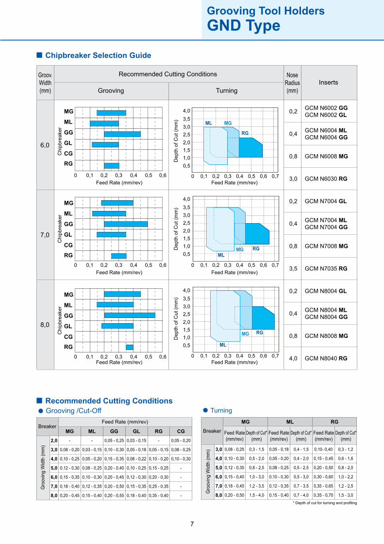
6,0
0,2 GCM N6002 GGGCM N6002 GL
0,4 GCM N6004 MLGCM N6004 GG
0,8 GCM N6008 MG
3,0 GCM N6030 RG
7,0
0,2 GCM N7004 GL
0,4 GCM N7004 MLGCM N7004 GG
0,8 GCM N7008 MG
3,5 GCM N7035 RG
8,0
0,2 GCM N8004 GL
0,4 GCM N8004 MLGCM N8004 GG
0,8 GCM N8008 MG
4,0 GCM N8040 RG
MG
ML
GG
GL
CGRG
0 0,1 0,2 0,3 0,4 0,5 0,6
MG
ML
GG
GL
CGRG
0 0,1 0,2 0,3 0,4 0,5 0,6
MG
ML
GG
GL
CGRG
0 0,1 0,2 0,3 0,4 0,5 0,6
0 0,1 0,2 0,3 0,4 0,5 0,6 0,7
0,51,01,52,02,53,03,54,0
ML
MG RG
0 0,1 0,2 0,3 0,4 0,5 0,6 0,7
0,51,01,52,02,53,03,54,0
MLMG RG
0 0,1 0,2 0,3 0,4 0,5 0,6 0,7
0,51,01,52,02,53,03,54,0
ML MG
RG
MG ML GG GL RG CG
2,0 - - 0,05 - 0,25 0,03 - 0,15 - 0,05 - 0,20
3,0 0,08 - 0,20 0,03 - 0,15 0,10 - 0,30 0,05 - 0,18 0,05 - 0,15 0,08 - 0,25
4,0 0,10 - 0,25 0,05 - 0,20 0,15 - 0,35 0,08 - 0,22 0,10 - 0,20 0,10 - 0,30
5,0 0,12 - 0,30 0,08 - 0,25 0,20 - 0,40 0,10 - 0,25 0,15 - 0,25 -
6,0 0,15 - 0,35 0,10 - 0,30 0,20 - 0,45 0,12 - 0,30 0,20 - 0,30 -
7,0 0,18 - 0,40 0,12 - 0,35 0,20 - 0,50 0,15 - 0,35 0,25 - 0,35 -
8,0 0,20 - 0,45 0,15 - 0,40 0,20 - 0,55 0,18 - 0,40 0,35 - 0,40 -
MG ML RG
3,0 0,08 - 0,25 0,3 - 1,5 0,05 - 0,18 0,4 - 1,5 0,10- 0,40 0,3 - 1,2
4,0 0,10 - 0,30 0,5 - 2,0 0,05 - 0,20 0,4 - 2,0 0,15 - 0,45 0,6 - 1,6
5,0 0,12 - 0,35 0,8 - 2,5 0,08 - 0,25 0,5 - 2,5 0,20 - 0,50 0,8 - 2,0
6,0 0,15 - 0,40 1,0 - 3,0 0,10 - 0,30 0,5 - 3,0 0,30 - 0,60 1,0 - 2,2
7,0 0,18 - 0,45 1,2 - 3,5 0,12 - 0,35 0,7 - 3,5 0,35 - 0,65 1,2 - 2,5
8,0 0,20 - 0,50 1,5 - 4,0 0,15 - 0,40 0,7 - 4,0 0,35 - 0,70 1,5 - 3,0
Chipbreaker Selection Guide
Recommended Cutting Conditions
Grooving TurningInserts
NoseRadius(mm)
Groov.Width(mm)
Chi
pbre
aker
Chi
pbre
aker
Chi
pbre
aker
Dep
th o
f Cut
(mm
)D
epth
of C
ut (m
m)
Dep
th o
f Cut
(mm
)
Feed Rate (mm/rev) Feed Rate (mm/rev)
Feed Rate (mm/rev) Feed Rate (mm/rev)
Feed Rate (mm/rev) Feed Rate (mm/rev)
Recommended Cutting Conditions
BreakerBreaker
Feed Rate (mm/rev)
Feed Rate(mm/rev)
Depth of Cut*(mm)
Feed Rate(mm/rev)
Depth of Cut*(mm)
Feed Rate(mm/rev)
Depth of Cut*(mm)
Gro
ovin
g W
idth
(mm
)
Gro
ovin
g W
idth
(mm
)
Grooving /Cut-Off Turning
Grooving Tool HoldersGND Type
* Depth of cut for turning and profiling
8
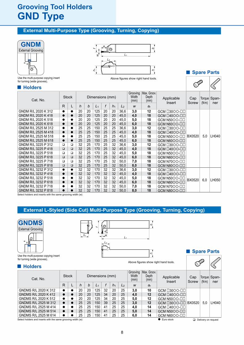
R L h b L1 f h1 L2 w ar
GNDM R/L 2020 K 312 l l 20 20 125 20 20 36,6 3,0 12 GCM □30-□□
BX0520
5,0 LH040
GNDM R/L 2020 K 418 l l 20 20 125 20 20 45,0 4,0 18 GCM □40-□□GNDM R/L 2020 K 518 l l 20 20 125 20 20 45,0 5,0 18 GCM N50-□□GNDM R/L 2020 K 618 l l 20 20 125 20 20 45,0 6,0 18 GCM N60-□□GNDM R/L 2525 M 312 l l 25 25 150 25 25 36,6 3,0 12 GCM □30-□□GNDM R/L 2525 M 418 l l 25 25 150 25 25 45,0 4,0 18 GCM □40-□□GNDM R/L 2525 M 518 l l 25 25 150 25 25 45,0 5,0 18 GCM N50-□□GNDM R/L 2525 M 618 l l 25 25 150 25 25 45,0 6,0 18 GCM N60-□□GNDM R/L 3225 P 312 q q 32 25 170 25 32 36,6 3,0 12 GCM □30-□□GNDM R/L 3225 P 418 q q 32 25 170 25 32 45,0 4,0 18 GCM □40-□□GNDM R/L 3225 P 518 q q 32 25 170 25 32 45,0 5,0 18 GCM N50-□□GNDM R/L 3225 P 618 q q 32 25 170 25 32 45,0 6,0 18 GCM N60-□□GNDM R/L 3225 P 718 q q 32 25 170 25 32 50,0 7,0 18 GCM N70-□□GNDM R/L 3225 P 818 q q 32 25 170 25 32 50,0 8,0 18 GCM N80-□□GNDM R/L 3232 P 312 l l 32 32 170 32 32 36,6 3,0 12 GCM □30-□□
BX0520 6,0 LH050
GNDM R/L 3232 P 418 l l 32 32 170 32 32 45,0 4,0 18 GCM □40-□□GNDM R/L 3232 P 518 l l 32 32 170 32 32 45,0 5,0 18 GCM N50-□□GNDM R/L 3232 P 618 l l 32 32 170 32 32 45,0 6,0 18 GCM N60-□□GNDM R/L 3232 P 718 l l 32 32 170 32 32 50,0 7,0 18 GCM N70-□□GNDM R/L 3232 P 818 l l 32 32 170 32 32 50,0 8,0 18 GCM N80-□□
R L h b L1 f h1 L2 w ar
GNDMS R/L 2020 K 312 l l 20 20 125 32 20 25 3,0 10 GCM □30-□□
BX0520
5,0 LH040
GNDMS R/L 2020 K 412 l l 20 20 125 34 20 25 4,0 12 GCM □40-□□GNDMS R/L 2020 K 512 l l 20 20 125 34 20 25 5,0 12 GCM N50-□□GNDMS R/L 2525 M 312 l l 25 25 150 39 25 25 3,0 12 GCM □30-□□GNDMS R/L 2525 M 414 l l 25 25 150 41 25 25 4,0 14 GCM □40-□□GNDMS R/L 2525 M 514 l l 25 25 150 41 25 25 5,0 14 GCM N50-□□GNDMS R/L 2525 M 614 l l 25 25 150 41 25 25 6,0 14 GCM N60-□□
GNDM
GNDMS
External L-Styled (Side Cut) Multi-Purpose Type (Grooving, Turning, Copying)
External Grooving
Above figures show right hand tools.Use the multi-purpose copying insert for turning (wide grooves).
External Grooving
Above figures show right hand tools.
Use the multi-purpose copying insert for turning (wide grooves).
Spare Parts
Cat. No.Dimensions (mm) Applicable
InsertStock
GroovingWidth(mm)
Max. Groov.Depth(mm) Cap
ScrewSpan-
nerTorque(N.m)
Spare Parts
Cat. No.Dimensions (mm) Applicable
InsertStock
GroovingWidth(mm)
Max. Groov.Depth(mm) Cap
ScrewSpan-
nerTorque(N.m)
Grooving Tool HoldersGND Type
Select holders and inserts with the same grooving width (w).
Select holders and inserts with the same grooving width (w).
Holders
Holders
External Multi-Purpose Type (Grooving, Turning, Copying)
l Euro stock q Delivery on request
9
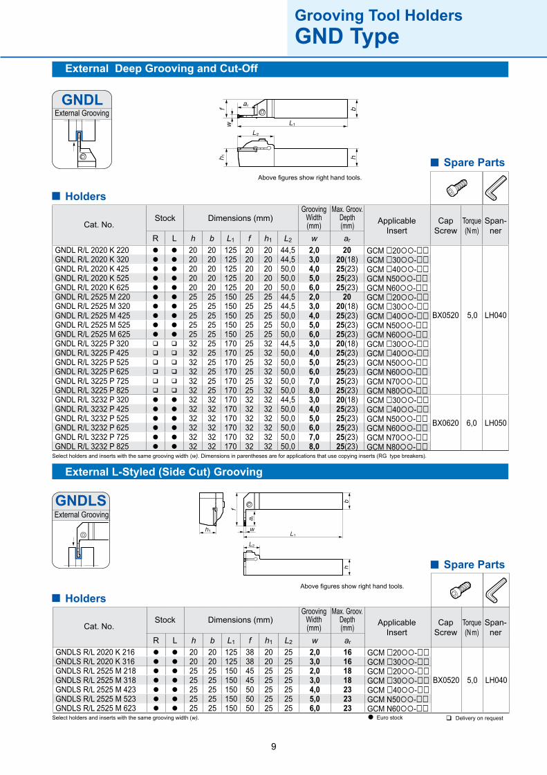
R L h b L1 f h1 L2 w ar
GNDLS R/L 2020 K 216 l l 20 20 125 38 20 25 2,0 16 GCM □20-□□
BX0520
5,0 LH040
GNDLS R/L 2020 K 316 l l 20 20 125 38 20 25 3,0 16 GCM □30-□□GNDLS R/L 2525 M 218 l l 25 25 150 45 25 25 2,0 18 GCM □20-□□GNDLS R/L 2525 M 318 l l 25 25 150 45 25 25 3,0 18 GCM □30-□□GNDLS R/L 2525 M 423 l l 25 25 150 50 25 25 4,0 23 GCM □40-□□GNDLS R/L 2525 M 523 l l 25 25 150 50 25 25 5,0 23 GCM N50-□□GNDLS R/L 2525 M 623 l l 25 25 150 50 25 25 6,0 23 GCM N60-□□
R L h b L1 f h1 L2 w ar
GNDL R/L 2020 K 220 l l 20 20 125 20 20 44,5 2,0 20 GCM □20-□□
BX0520
5,0 LH040
GNDL R/L 2020 K 320 l l 20 20 125 20 20 44,5 3,0 20(18) GCM □30-□□GNDL R/L 2020 K 425 l l 20 20 125 20 20 50,0 4,0 25(23) GCM □40-□□GNDL R/L 2020 K 525 l l 20 20 125 20 20 50,0 5,0 25(23) GCM N50-□□GNDL R/L 2020 K 625 l l 20 20 125 20 20 50,0 6,0 25(23) GCM N60-□□GNDL R/L 2525 M 220 l l 25 25 150 25 25 44,5 2,0 20 GCM □20-□□GNDL R/L 2525 M 320 l l 25 25 150 25 25 44,5 3,0 20(18) GCM □30-□□GNDL R/L 2525 M 425 l l 25 25 150 25 25 50,0 4,0 25(23) GCM □40-□□GNDL R/L 2525 M 525 l l 25 25 150 25 25 50,0 5,0 25(23) GCM N50-□□GNDL R/L 2525 M 625 l l 25 25 150 25 25 50,0 6,0 25(23) GCM N60-□□GNDL R/L 3225 P 320 q q 32 25 170 25 32 44,5 3,0 20(18) GCM □30-□□GNDL R/L 3225 P 425 q q 32 25 170 25 32 50,0 4,0 25(23) GCM □40-□□GNDL R/L 3225 P 525 q q 32 25 170 25 32 50,0 5,0 25(23) GCM N50-□□GNDL R/L 3225 P 625 q q 32 25 170 25 32 50,0 6,0 25(23) GCM N60-□□GNDL R/L 3225 P 725 q q 32 25 170 25 32 50,0 7,0 25(23) GCM N70-□□GNDL R/L 3225 P 825 q q 32 25 170 25 32 50,0 8,0 25(23) GCM N80-□□GNDL R/L 3232 P 320 l l 32 32 170 32 32 44,5 3,0 20(18) GCM □30-□□
BX0620 6,0 LH050
GNDL R/L 3232 P 425 l l 32 32 170 32 32 50,0 4,0 25(23) GCM □40-□□GNDL R/L 3232 P 525 l l 32 32 170 32 32 50,0 5,0 25(23) GCM N50-□□GNDL R/L 3232 P 625 l l 32 32 170 32 32 50,0 6,0 25(23) GCM N60-□□GNDL R/L 3232 P 725 l l 32 32 170 32 32 50,0 7,0 25(23) GCM N70-□□GNDL R/L 3232 P 825 l l 32 32 170 32 32 50,0 8,0 25(23) GCM N80-□□
GNDL
GNDLS
External Deep Grooving and Cut-Off
External L-Styled (Side Cut) Grooving
External Grooving
Above figures show right hand tools.
External Grooving
Above figures show right hand tools.
Spare Parts
Cat. No.Dimensions (mm) Applicable
InsertStock
GroovingWidth(mm)
Max. Groov.Depth(mm) Cap
ScrewSpan-
nerTorque(N.m)
Spare Parts
Cat. No.Dimensions (mm) Applicable
InsertStock
GroovingWidth(mm)
Max. Groov.Depth(mm) Cap
ScrewSpan-
nerTorque(N.m)
Grooving Tool HoldersGND Type
Select holders and inserts with the same grooving width (w). Dimensions in parentheses are for applications that use copying inserts (RG type breakers).
Select holders and inserts with the same grooving width (w).
Holders
Holders
l Euro stock q Delivery on request
10
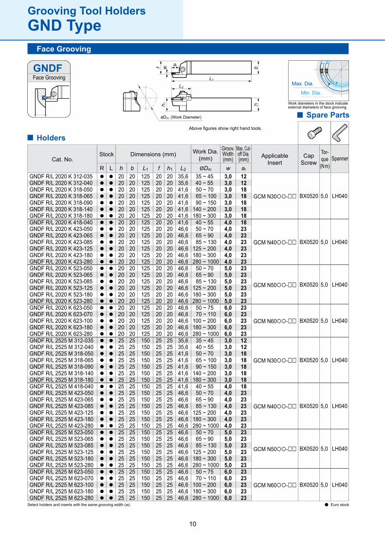
R L h b L1 f h1 L2 ØDm w ar
GNDF R/L 2020 K 312-035 l l 20 20 125 20 20 35,6 35 ~ 45 3,0 12
GCM N30-□□ BX0520 5,0 LH040
GNDF R/L 2020 K 312-040 l l 20 20 125 20 20 35,6 40 ~ 55 3,0 12GNDF R/L 2020 K 318-050 l l 20 20 125 20 20 41,6 50 ~ 70 3,0 18GNDF R/L 2020 K 318-065 l l 20 20 125 20 20 41,6 65 ~ 100 3,0 18GNDF R/L 2020 K 318-090 l l 20 20 125 20 20 41,6 90 ~ 150 3,0 18GNDF R/L 2020 K 318-140 l l 20 20 125 20 20 41,6 140 ~ 200 3,0 18GNDF R/L 2020 K 318-180 l l 20 20 125 20 20 41,6 180 ~ 300 3,0 18GNDF R/L 2020 K 418-040 l l 20 20 125 20 20 41,6 40 ~ 55 4,0 18
GCM N40-□□ BX0520 5,0 LH040
GNDF R/L 2020 K 423-050 l l 20 20 125 20 20 46,6 50 ~ 70 4,0 23GNDF R/L 2020 K 423-065 l l 20 20 125 20 20 46,6 65 ~ 90 4,0 23GNDF R/L 2020 K 423-085 l l 20 20 125 20 20 46,6 85 ~ 130 4,0 23GNDF R/L 2020 K 423-125 l l 20 20 125 20 20 46,6 125 ~ 200 4,0 23GNDF R/L 2020 K 423-180 l l 20 20 125 20 20 46,6 180 ~ 300 4,0 23GNDF R/L 2020 K 423-280 l l 20 20 125 20 20 46,6 280 ~ 1000 4,0 23GNDF R/L 2020 K 523-050 l l 20 20 125 20 20 46,6 50 ~ 70 5,0 23
GCM N50-□□ BX0520 5,0 LH040
GNDF R/L 2020 K 523-065 l l 20 20 125 20 20 46,6 65 ~ 90 5,0 23GNDF R/L 2020 K 523-085 l l 20 20 125 20 20 46,6 85 ~ 130 5,0 23GNDF R/L 2020 K 523-125 l l 20 20 125 20 20 46,6 125 ~ 200 5,0 23GNDF R/L 2020 K 523-180 l l 20 20 125 20 20 46,6 180 ~ 300 5,0 23GNDF R/L 2020 K 523-280 l l 20 20 125 20 20 46,6 280 ~ 1000 5,0 23GNDF R/L 2020 K 623-050 l l 20 20 125 20 20 46,6 50 ~ 75 6,0 23
GCM N60-□□ BX0520 5,0 LH040GNDF R/L 2020 K 623-070 l l 20 20 125 20 20 46,6 70 ~ 110 6,0 23GNDF R/L 2020 K 623-100 l l 20 20 125 20 20 46,6 100 ~ 200 6,0 23GNDF R/L 2020 K 623-180 l l 20 20 125 20 20 46,6 180 ~ 300 6,0 23GNDF R/L 2020 K 623-280 l l 20 20 125 20 20 46,6 280 ~ 1000 6,0 23GNDF R/L 2525 M 312-035 l l 25 25 150 25 25 35,6 35 ~ 45 3,0 12
GCM N30-□□ BX0520 5,0 LH040
GNDF R/L 2525 M 312-040 l l 25 25 150 25 25 35,6 40 ~ 55 3,0 12GNDF R/L 2525 M 318-050 l l 25 25 150 25 25 41,6 50 ~ 70 3,0 18GNDF R/L 2525 M 318-065 l l 25 25 150 25 25 41,6 65 ~ 100 3,0 18GNDF R/L 2525 M 318-090 l l 25 25 150 25 25 41,6 90 ~ 150 3,0 18GNDF R/L 2525 M 318-140 l l 25 25 150 25 25 41,6 140 ~ 200 3,0 18GNDF R/L 2525 M 318-180 l l 25 25 150 25 25 41,6 180 ~ 300 3,0 18GNDF R/L 2525 M 418-040 l l 25 25 150 25 25 41,6 40 ~ 55 4,0 18
GCM N40-□□ BX0520 5,0 LH040
GNDF R/L 2525 M 423-050 l l 25 25 150 25 25 46,6 50 ~ 70 4,0 23GNDF R/L 2525 M 423-065 l l 25 25 150 25 25 46,6 65 ~ 90 4,0 23GNDF R/L 2525 M 423-085 l l 25 25 150 25 25 46,6 85 ~ 130 4,0 23GNDF R/L 2525 M 423-125 l l 25 25 150 25 25 46,6 125 ~ 200 4,0 23GNDF R/L 2525 M 423-180 l l 25 25 150 25 25 46,6 180 ~ 300 4,0 23GNDF R/L 2525 M 423-280 l l 25 25 150 25 25 46,6 280 ~ 1000 4,0 23GNDF R/L 2525 M 523-050 l l 25 25 150 25 25 46,6 50 ~ 70 5,0 23
GCM N50-□□ BX0520 5,0 LH040
GNDF R/L 2525 M 523-065 l l 25 25 150 25 25 46,6 65 ~ 90 5,0 23GNDF R/L 2525 M 523-085 l l 25 25 150 25 25 46,6 85 ~ 130 5,0 23GNDF R/L 2525 M 523-125 l l 25 25 150 25 25 46,6 125 ~ 200 5,0 23GNDF R/L 2525 M 523-180 l l 25 25 150 25 25 46,6 180 ~ 300 5,0 23GNDF R/L 2525 M 523-280 l l 25 25 150 25 25 46,6 280 ~ 1000 5,0 23GNDF R/L 2525 M 623-050 l l 25 25 150 25 25 46,6 50 ~ 75 6,0 23
GCM N60-□□ BX0520 5,0 LH040GNDF R/L 2525 M 623-070 l l 25 25 150 25 25 46,6 70 ~ 110 6,0 23GNDF R/L 2525 M 623-100 l l 25 25 150 25 25 46,6 100 ~ 200 6,0 23GNDF R/L 2525 M 623-180 l l 25 25 150 25 25 46,6 180 ~ 300 6,0 23GNDF R/L 2525 M 623-280 l l 25 25 150 25 25 46,6 280 ~ 1000 6,0 23
øDm
GNDF
Grooving Tool HoldersGND Type
Spare Parts
ApplicableInsert
CapScrew
SpannerWork Dia.
(mm)
Groov.Width (mm)
Max. Cut-off Dia.(mm)Cat. No.
Dimensions (mm)Stock Tor-que
(N.m)
Face Grooving
Select holders and inserts with the same grooving width (w).
Above figures show right hand tools.
Face Grooving
(Work Diameter)
Max. Dia.
Min. Dia.
Work diameters in the stock indicate external diameters of face grooving.
Holders
l Euro stock
11
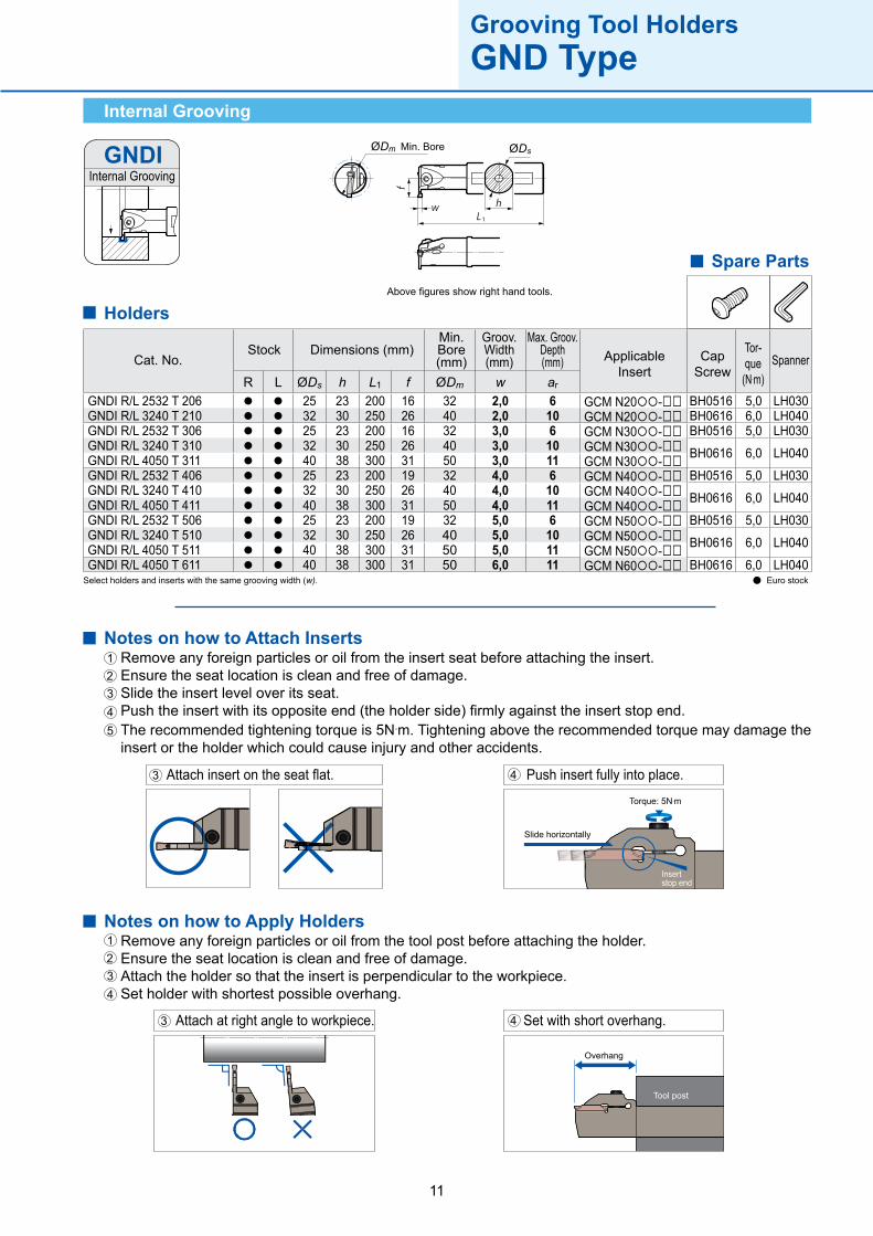
R L ØDs h L1 f ØDm w ar
GNDI R/L 2532 T 206 l l 25 23 200 16 32 2,0 6 GCM N20-□□ BH0516 5,0 LH030GNDI R/L 3240 T 210 l l 32 30 250 26 40 2,0 10 GCM N20-□□ BH0616 6,0 LH040GNDI R/L 2532 T 306 l l 25 23 200 16 32 3,0 6 GCM N30-□□ BH0516 5,0 LH030GNDI R/L 3240 T 310 l l 32 30 250 26 40 3,0 10 GCM N30-□□ BH0616 6,0 LH040GNDI R/L 4050 T 311 l l 40 38 300 31 50 3,0 11 GCM N30-□□GNDI R/L 2532 T 406 l l 25 23 200 19 32 4,0 6 GCM N40-□□ BH0516 5,0 LH030GNDI R/L 3240 T 410 l l 32 30 250 26 40 4,0 10 GCM N40-□□ BH0616 6,0 LH040GNDI R/L 4050 T 411 l l 40 38 300 31 50 4,0 11 GCM N40-□□GNDI R/L 2532 T 506 l l 25 23 200 19 32 5,0 6 GCM N50-□□ BH0516 5,0 LH030GNDI R/L 3240 T 510 l l 32 30 250 26 40 5,0 10 GCM N50-□□ BH0616 6,0 LH040GNDI R/L 4050 T 511 l l 40 38 300 31 50 5,0 11 GCM N50-□□GNDI R/L 4050 T 611 l l 40 38 300 31 50 6,0 11 GCM N60-□□ BH0616 6,0 LH040
GNDI ØDsØDm
Notes on how to Attach InsertsRemove any foreign particles or oil from the insert seat before attaching the insert.Ensure the seat location is clean and free of damage.Slide the insert level over its seat.Push the insert with its opposite end (the holder side) firmly against the insert stop end.The recommended tightening torque is 5N.m. Tightening above the recommended torque may damage the insert or the holder which could cause injury and other accidents.
12345
Slide horizontally
Torque: 5N.m
Insert stop end
Attach insert on the seat flat.3 Push insert fully into place.4
Attach at right angle to workpiece. Set with short overhang.
Overhang
Tool post
3 4
Notes on how to Apply HoldersRemove any foreign particles or oil from the tool post before attaching the holder.Ensure the seat location is clean and free of damage.Attach the holder so that the insert is perpendicular to the workpiece.Set holder with shortest possible overhang.
1234
Grooving Tool HoldersGND Type
Spare Parts
Cat. No.Dimensions (mm)Stock Applicable
InsertCap
ScrewSpanner
Max. Groov.Depth(mm)
Groov.Width (mm)
Min. Bore (mm)
Tor-que
(N.m)
Internal Grooving
Above figures show right hand tools.
Internal Grooving
Min. Bore
Select holders and inserts with the same grooving width (w).
Holders
l Euro stock
12
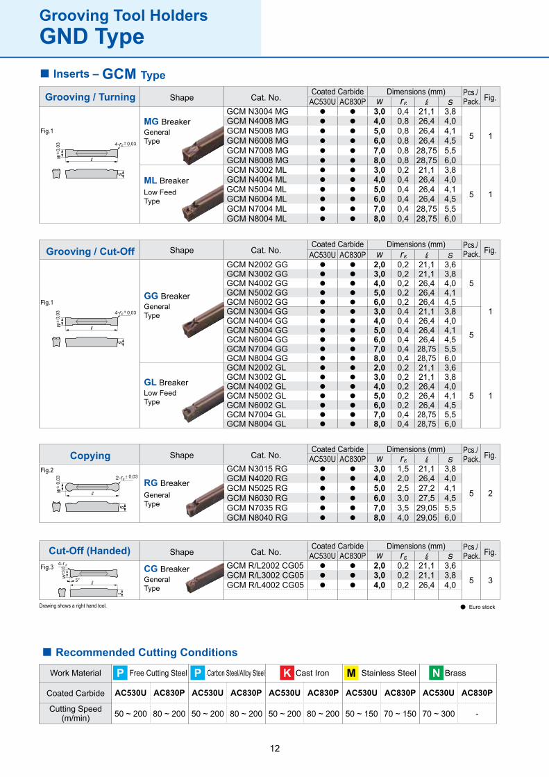
AC530U AC830PGCM N3004 MG l l 3,0 0,4 21,1 3,8
5 1
GCM N4008 MG l l 4,0 0,8 26,4 4,0GCM N5008 MG l l 5,0 0,8 26,4 4,1GCM N6008 MG l l 6,0 0,8 26,4 4,5GCM N7008 MG l l 7,0 0,8 28,75 5,5GCM N8008 MG l l 8,0 0,8 28,75 6,0GCM N3002 ML l l 3,0 0,2 21,1 3,8
5 1
GCM N4004 ML l l 4,0 0,4 26,4 4,0GCM N5004 ML l l 5,0 0,4 26,4 4,1GCM N6004 ML l l 6,0 0,4 26,4 4,5GCM N7004 ML l l 7,0 0,4 28,75 5,5GCM N8004 ML l l 8,0 0,4 28,75 6,0
0,03
0,03
AC530U AC830PGCM N2002 GG l l 2,0 0,2 21,1 3,6
5
1
GCM N3002 GG l l 3,0 0,2 21,1 3,8GCM N4002 GG l l 4,0 0,2 26,4 4,0GCM N5002 GG l l 5,0 0,2 26,4 4,1GCM N6002 GG l l 6,0 0,2 26,4 4,5GCM N3004 GG l l 3,0 0,4 21,1 3,8
5
GCM N4004 GG l l 4,0 0,4 26,4 4,0GCM N5004 GG l l 5,0 0,4 26,4 4,1GCM N6004 GG l l 6,0 0,4 26,4 4,5GCM N7004 GG l l 7,0 0,4 28,75 5,5GCM N8004 GG l l 8,0 0,4 28,75 6,0GCM N2002 GL l l 2,0 0,2 21,1 3,6
5 1
GCM N3002 GL l l 3,0 0,2 21,1 3,8GCM N4002 GL l l 4,0 0,2 26,4 4,0GCM N5002 GL l l 5,0 0,2 26,4 4,1GCM N6002 GL l l 6,0 0,2 26,4 4,5GCM N7004 GL l l 7,0 0,4 28,75 5,5GCM N8004 GL l l 8,0 0,4 28,75 6,0
0,03
0,03
AC530U AC830PGCM R/L2002 CG05 l l 2,0 0,2 21,1 3,6
5 3GCM R/L3002 CG05 l l 3,0 0,2 21,1 3,8GCM R/L4002 CG05 l l 4,0 0,2 26,4 4,0
0,03
AC530U AC830PGCM N3015 RG l l 3,0 1,5 21,1 3,8
5 2
GCM N4020 RG l l 4,0 2,0 26,4 4,0GCM N5025 RG l l 5,0 2,5 27,2 4,1GCM N6030 RG l l 6,0 3,0 27,5 4,5GCM N7035 RG l l 7,0 3,5 29,05 5,5GCM N8040 RG l l 8,0 4,0 29,05 6,0
0,03
0,03
AC530U AC830P AC530U AC830P AC530U AC830P AC530U AC830P AC530U AC830P
50 ~ 200 80 ~ 200 50 ~ 200 80 ~ 200 50 ~ 200 80 ~ 200 50 ~ 150 70 ~ 150 70 ~ 300 -
P P M NK
Inserts –
Recommended Cutting Conditions
Work Material
Coated Carbide
Cutting Speed(m/min)
Free Cutting Steel Carbon Steel/Alloy Steel Cast Iron Stainless Steel Brass
Grooving Tool HoldersGND Type
Shape Cat. No.Coated Carbide Dimensions (mm) Pcs./
Pack. Fig.
Fig.1
Shape Cat. No.Coated Carbide Dimensions (mm) Pcs./
Pack. Fig.
Fig.2
Shape Cat. No.Coated Carbide Dimensions (mm) Pcs./
Pack. Fig.
Fig.3
Drawing shows a right hand tool.
Shape Cat. No.Coated Carbide Dimensions (mm) Pcs./
Pack. Fig.
Fig.1
GCM Type
Grooving / Turning
MG BreakerGeneralType
ML BreakerLow FeedType
GG BreakerGeneralType
GL BreakerLow FeedType
CG BreakerGeneralType
RG BreakerGeneralType
Grooving / Cut-Off
Copying
Cut-Off (Handed)
l Euro stock
13
G -C
C: 7°
2
NRL
N4
1
M3
20 2,030 3,040 4,050 5,060 6,070 7,080 8,0
305
02 0,204 0,408 0,815 1,520 2,025 2,530 3,0
026
MGMLGGGLCGRG
G G7
G N D 25 25 M 123 ( - 0 3 5 ) -
7 8
M R1 4 5 62 3 9
ML
MSLSIF
2
RL
3
20 2025 2532 32
4
20 2025 2532 32
5
2 2,03 3,04 4,05 5,06 6,07 7,08 8,0
7
10 1012 1218 1820 2023 2325 25
8
K 125M 150P 170
6
Symbol
Symbol Symbol Symbol
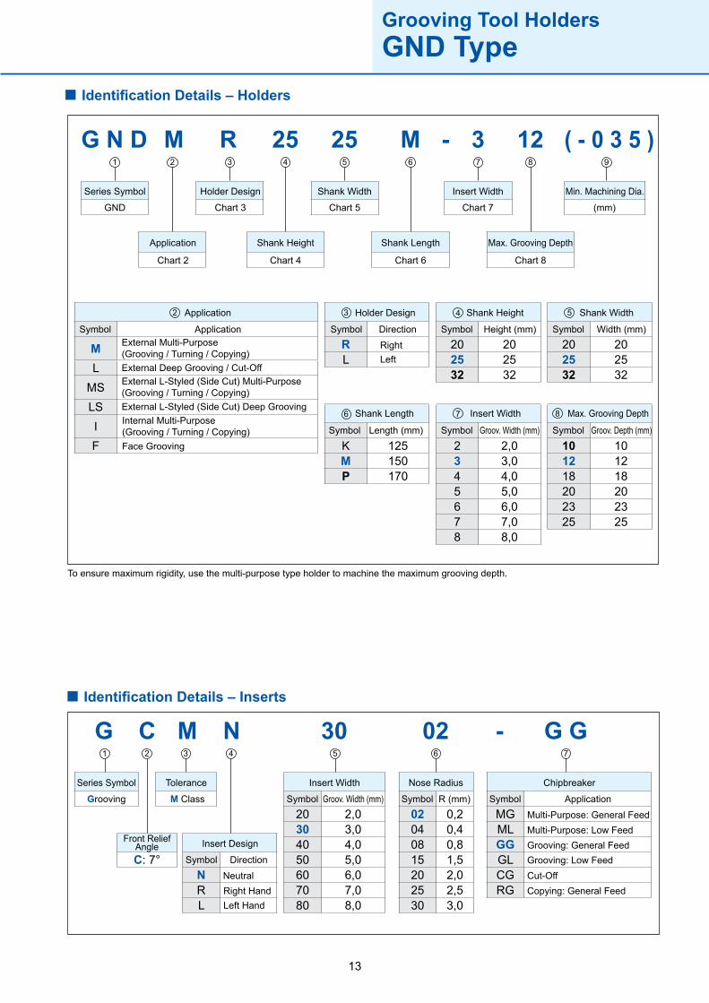
Series Symbol Tolerance
Front ReliefAngle Insert Design
Insert Width Nose Radius Chipbreaker
Grooving M Class
Direction
NeutralRight HandLeft Hand
Groov. Width (mm) R (mm) Application
Multi-Purpose: General FeedMulti-Purpose: Low FeedGrooving: General FeedGrooving: Low Feed
Copying: General FeedCut-Off
Identification Details – Holders
Grooving Tool HoldersGND Type
Series Symbol Holder Design Shank Width Insert Width
Application Shank Height Shank Length
Min. Machining Dia.
Max. Grooving Depth
GND Chart 3 Chart 5 Chart 7
Chart 2 Chart 4 Chart 6 Chart 8
(mm)
Application Holder Design Shank Height Shank Width
Shank Length Insert Width Max. Grooving Depth
Symbol Symbol Symbol Symbol
Symbol Symbol Symbol
Application Direction Height (mm) Width (mm)
Length (mm) Groov. Width (mm) Groov. Depth (mm)
External Multi-Purpose(Grooving / Turning / Copying)
External L-Styled (Side Cut) Multi-Purpose(Grooving / Turning / Copying)
External Deep Grooving / Cut-Off
External L-Styled (Side Cut) Deep Grooving
Face Grooving
Internal Multi-Purpose(Grooving / Turning / Copying)
To ensure maximum rigidity, use the multi-purpose type holder to machine the maximum grooving depth.
Identification Details – Inserts
Right Left
14
ø56,8
ø44
1 12 23 3
Grooving Tool HoldersGND Type
Holder:
Insert:
Groovingwidth: Cuttingconditions:
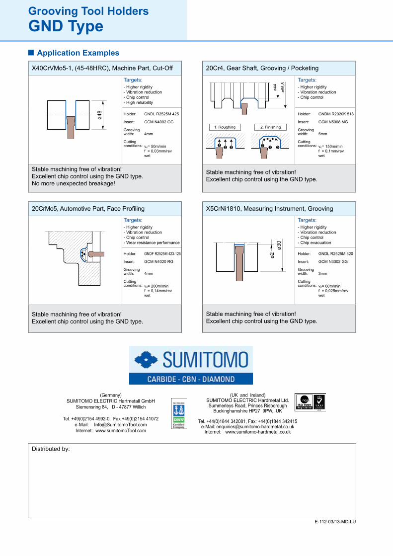
GNDL R2525M 425
GCM N4002 GG
4mm
vc= 50m/minf = 0,03mm/revwet
Targets:- Higher rigidity- Vibration reduction- Chip control- High reliability
X40CrVMo5-1, (45-48HRC), Machine Part, Cut-Off
Stable machining free of vibration!Excellent chip control using the GND type.No more unexpected breakage!
Holder:
Insert:
Groovingwidth:
Cuttingconditions:
GNDM R2020K 518
GCM N5008 MG
5mm
vc= 150m/minf = 0,1mm/revwet
Targets:- Higher rigidity- Vibration reduction- Chip control
Gear Shaft, Grooving / Pocketing
Stable machining free of vibration!Excellent chip control using the GND type.
Holder:
Insert:
Groovingwidth: Cuttingconditions:
GNDL R2525M 320
GCM N3002 GG
3mm
vc= 60m/minf = 0,025mm/revwet
Targets:- Higher rigidity- Vibration reduction- Chip control- Chip evacuation
X5CrNi1810, Measuring Instrument, Grooving
Stable machining free of vibration!Excellent chip control using the GND type.
Holder:
Insert:
Groovingwidth: Cuttingconditions:
GNDF R2525M 423-125
GCM N4020 RG
4mm
vc= 200m/minf = 0,14mm/revwet
Targets:- Higher rigidity- Vibration reduction- Chip control- Wear resistance performance
20CrMo5, Automotive Part, Face Profiling
Stable machining free of vibration!Excellent chip control using the GND type.
20Cr4,
1. Roughing 2. Finishing
Application Examples
(Germany)SUMITOMO ELECTRIC Hartmetall GmbH
Siemensring 84, D - 47877 Willich
Tel. +49(0)2154 4992-0, Fax +49(0)2154 41072e-Mail: [email protected]: www.sumitomoTool.com
(UK and Ireland)SUMITOMO ELECTRIC Hardmetal Ltd.Summerleys Road, Princes Risborough
Buckinghamshire HP27 9PW, UK
Tel. +44(0)1844 342081, Fax: +44(0)1844 342415e-Mail: [email protected]
Internet: www.sumitomo-hardmetal.co.uk
Distributed by:
E-112-03/13-MD-LU


![FCM Workflow using GCM. Agenda Polling Mechanism What is GCM Need / advantages of GCM GCM Architecture Working of GCM GCM – Send to Sync [ HTTP ] and.](https://static.fdocuments.us/doc/165x107/5697bfba1a28abf838ca07e2/fcm-workflow-using-gcm-agenda-polling-mechanism-what-is-gcm-need-advantages.jpg)