GRIZZLY - Alcor inc.v...PRE-START CHECKLIST .....7 PRE-HOISTING CHECKLIST.....7 RULES FOR HOISTING...
17
1 ©Alcor 2016 All Rights Reserved GRIZZLY OPERATOR’S INSTRUCTION MANUAL MODEL: ____________________ ENGINE MODEL: _______________ SERIAL: _____________________ ENGINE SERIAL: _______________ DATE OF PURCHASE: ____________ PURCHASED FROM: __________________________ WARNING: THIS PRODUCT IS DESIGNED AND MANUFACTURED TO PROVIDE SAFE AND DEPENDABLE SERVICE IF OPERATED ACCORDING TO INSTRUCTIONS. THE MANUFACTURER PROVIDES THE FOLLOWING INSTRUCTIONS FOR USE AND CARE OF THIS EQUIPMENT AND RELIES UPON THE PURCHASER TO SEE TO IT THAT THESE INSTRUCTIONS ARE MADE CLEAR TO THE PERSONS WHO WILL ACTUALLY BE USING THE EQUIPMENT. FAILURE TO DO SO COULD RESULT IN SERIOUS INJURY OR EQUIPMENT DAMAGE. GRIZZLY EQUIPMENT 9475 PASCAL GAGNON STREET, ST-LÉONARD, QUEBEC, CANADA TEL: (514) 325-1260 / 1-888-325-9953 FAX: (514) 325-9952 E-MAIL: [email protected] Web site: www.grizzlyequip.com 502000 / 503 000
Transcript of GRIZZLY - Alcor inc.v...PRE-START CHECKLIST .....7 PRE-HOISTING CHECKLIST.....7 RULES FOR HOISTING...

1
©Alcor 2016 All Rights Reserved
GRIZZLY
OPERATOR’S INSTRUCTION MANUAL
MODEL: ____________________ ENGINE MODEL: _______________
SERIAL: _____________________ ENGINE SERIAL: _______________
DATE OF PURCHASE: ____________
PURCHASED FROM: __________________________
WARNING: THIS PRODUCT IS DESIGNED AND MANUFACTURED TO
PROVIDE SAFE AND DEPENDABLE SERVICE IF OPERATED
ACCORDING TO INSTRUCTIONS. THE MANUFACTURER
PROVIDES THE FOLLOWING INSTRUCTIONS FOR USE AND
CARE OF THIS EQUIPMENT AND RELIES UPON THE
PURCHASER TO SEE TO IT THAT THESE INSTRUCTIONS ARE
MADE CLEAR TO THE PERSONS WHO WILL ACTUALLY BE
USING THE EQUIPMENT. FAILURE TO DO SO COULD RESULT
IN SERIOUS INJURY OR EQUIPMENT DAMAGE.
GRIZZLY EQUIPMENT 9475 PASCAL GAGNON STREET, ST-LÉONARD, QUEBEC, CANADA
TEL: (514) 325-1260 / 1-888-325-9953 FAX: (514) 325-9952
E-MAIL: [email protected] Web site: www.grizzlyequip.com
502000 / 503 000

2
©Alcor 2016 All Rights Reserved
INDEX
INTRODUCTION ................................................................................................................................................................................................ 3
PREPARATION .................................................................................................................................................................................................. 4
OPERATOR; .................................................................................................................................................................................................. 4
WEAR PROPER ATTIRE ..................................................................................................................................................................................... 4
ROOF PREPARATION ........................................................................................................................................................................................ 4
INSPECT ROOF DECK .................................................................................................................................................................................... 4
WARNING LINE SYSTEM .............................................................................................................................................................................. 4
SPECIAL WARRANTY NOTES ........................................................................................................................................................................ 4
SAFETY INSTRUCTIONS ..................................................................................................................................................................................... 5
NAME PLATE AND SERIAL NUMBER TAGS ....................................................................................................................................................... 5
SAFETY FEATURES MECHANICAL POWER UNIT / SAFETY FIRST ....................................................................................................................... 6
SAFETY FEATURES HYDRAULIC POWER UNIT / SAFETY FIRST .......................................................................................................................... 6
CAPACITIES .................................................................................................................................................................................................. 6
POWER UNIT WEIGHT ................................................................................................................................................................................. 6
WIRE ROPE ................................................................................................................................................................................................... 6
BUILD-UP ..................................................................................................................................................................................................... 7
SAFETY HOOK .............................................................................................................................................................................................. 7
CAPACITY ..................................................................................................................................................................................................... 7
PRE-START CHECKLIST ................................................................................................................................................................................. 7
PRE-HOISTING CHECKLIST ............................................................................................................................................................................ 7
RULES FOR HOISTING .................................................................................................................................................................................. 8
RAISING TO ROOF ........................................................................................................................................................................................ 9
ASSEMBLY ...................................................................................................................................................................................................... 10
INSTALLING POWER UNIT .............................................................................................................................................................................. 12
OPERATING THE MECHANICAL POWER UNIT (502500) ................................................................................................................................. 12
HOISTING THE LOAD .................................................................................................................................................................................. 12
LOWERING THE LOAD ................................................................................................................................................................................ 13
OPERATING THE HYDRAULIC POWER UNIT (503 500) ................................................................................................................................... 14
HOISTING THE LOAD .................................................................................................................................................................................. 14
LOWERING THE LOAD ................................................................................................................................................................................ 15
SAFETY HAZARDS ........................................................................................................................................................................................... 16
Falls ............................................................................................................................................................................................................ 16
Burns .......................................................................................................................................................................................................... 16
Heavy Lifting .............................................................................................................................................................................................. 16
Fire/Explosion ............................................................................................................................................................................................ 17
Electrocution ............................................................................................................................................................................................. 17
Falling Objects ........................................................................................................................................................................................... 17
Flying Objects ............................................................................................................................................................................................ 17
Unguarded Machinery ............................................................................................................................................................................... 17
3
©Alcor 2016 All Rights Reserved
INTRODUCTION
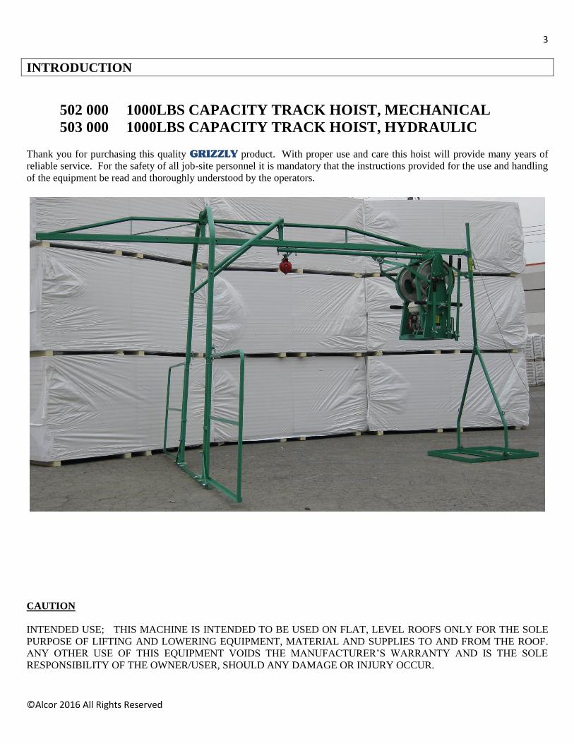
502 000 1000LBS CAPACITY TRACK HOIST, MECHANICAL
503 000 1000LBS CAPACITY TRACK HOIST, HYDRAULIC
Thank you for purchasing this quality GRIZZLY product. With proper use and care this hoist will provide many years of
reliable service. For the safety of all job-site personnel it is mandatory that the instructions provided for the use and handling
of the equipment be read and thoroughly understood by the operators.
CAUTION
INTENDED USE; THIS MACHINE IS INTENDED TO BE USED ON FLAT, LEVEL ROOFS ONLY FOR THE SOLE
PURPOSE OF LIFTING AND LOWERING EQUIPMENT, MATERIAL AND SUPPLIES TO AND FROM THE ROOF.
ANY OTHER USE OF THIS EQUIPMENT VOIDS THE MANUFACTURER’S WARRANTY AND IS THE SOLE
RESPONSIBILITY OF THE OWNER/USER, SHOULD ANY DAMAGE OR INJURY OCCUR.

4
©Alcor 2016 All Rights Reserved
PREPARATION
OPERATOR; START BY READING AND FULLY UNDERSTANDING OPERATING INSTRUCTIONS. IF SOMETHING IS NOT
UNDERSTOOD, HAVE SOMEONE ELSE READ AND EXPLAIN THE INSTRUCTIONS TO THE OPERATOR OR
CALL THE MANUFACTURER FOR INFORMATION. AN UNINFORMED OPERATOR CAN SUBJECT HIMSELF
AND OTHERS TO DEATH OR SERIOUS INJURY.
WEAR PROPER ATTIRE
Safety glasses are recommended and must be worn if any roof cutting or scraping is being done in the vicinity. Safety glasses
and or face shield are also necessary when working with hot stuff.
Wear properly fitting clothes. Tight clothing can restrict movement and slow down reaction time in a dangerous situation.
Loose fitting clothing can be dangerous and cause serious injury if it gets caught in moving mechanical parts. Wear a long-
sleeved shirt, buttoned at the cuffs, safety shoes, and pants without cuffs, and knit wrist type gloves.
A hard hat must be worn by operator when working on a job site.
ROOF PREPARATION
INSPECT ROOF DECK
Before allowing equipment and personnel access to roof, make certain roof is strong enough to support the weight. Check
load limits of deck with owner, builder or architect. Clear the work area of all potentially dangerous obstacles that could
cause personal injury to the operator or others. Keep unauthorized people away from construction area. Check to see that all
roof openings are guarded to protect against falls.
WARNING LINE SYSTEM
When operating parallel to roof edge warning line system must be at least six feet from edge. When operating perpendicular
to edge warning line must be ten feet from roof edge.
WARNING; THESE HOISTS ARE NOT FOR TRANSPORTING OR HANDLING OF PERSONS. NO
PERSONS SHALL BE ALLOWED TO RIDE ON MATERIAL HOISTS.
SPECIAL WARRANTY NOTES
Manufacturer is NOT responsible for warranty if equipment is subject to unusual, improper use or abuse by person(s) using
the equipment, or for purposes for which it was not intended for. Warranty is further void if any modifications are made to
the equipment by the owner. Collisions, overturn, dropping, water damage, or damage to equipment after being shipped by
manufacturer, also voids the warranty.
PLEASE READ BEFORE HANDLING HOIST
5
©Alcor 2016 All Rights Reserved
SAFETY INSTRUCTIONS
1. After the hoist is assembled, make sure that all pins on the frame and power unit are properly placed.
2. Verify that all nuts and bolts on the frame are properly fastened. If any are loose, make sure that they are tightened
before operating the hoist to ensure the operator’s safety and the safety of others.
3. The cable located on the back of the track must be fastened to a secure object on the roof in a manner that it will not
come loose under pressure.
4. The fences located on the front frame must be swung outward to protect the operator from accidentally falling off the
roof edge while operating the hoist.
5. Make sure to always have enough counterweights on the rear weight base. It is important to use 1-1/2 times the
weight capacity of the hoist; 1500lbs. After placing the counterweights secure them to the hoist frame using a wire
cable or chain to prevent them from being removed of falling off of base in the event of sudden impact load.
6. Always keep in mind the maximum rated load of the hoist that you are using.
WARNING; NEVER ATTEMPT TO LIFT MORE THAN THE MAXIMUM RATED LIFT LIMIT,
DAMAGE TO THE HOIST AND/OR INJURY TO THE OPERATOR COULD RESULT.
7. Check the hoist cable for broken strands, if any are found then the hoist cable should be immediately replaced.
8. Check the hoist braking system for wear and proper operation by lifting a load one or two feet off the ground and
applying brake to check it’s performance, adjust if necessary. Do not use hoist if unable to adjust properly.
WARNING; DO NOT APPLY GREASE OR OILY SUBSTANCES ON THE BRAKE ROPE OR ON THE
BRAKE DRUM.
9. Always test the running of the hoist with a small amount of weight before lifting very heavy objects.
10. Grease all moving parts on the hoist power unit (drum bearings, idler) verify the belt condition.
11. The engine oil and fuel level should be checked and topped off before starting. For all other engine maintenance,
please refer to the engine manual.
12. When using the 503500 hydraulic power unit, check for leaks and repair if any are found before using, make sure
hydraulic oil level is two inches (5cm) from the top of the tank, if water has gotten in to the tank, oil will be milky, do
not use, flush system and refill with fresh oil before using, use AW32 hydraulic oil
13. Check the brake safety sprocket on the Hydraulic power unit for wear to the teeth and replace if damaged
14. You are now ready to start the engine.
NAME PLATE AND SERIAL NUMBER TAGS
The name plate and serial number tag is located on the power unit frame. Use the model number and serial number when
referring to your mechanical or hydraulic hoist power unit for parts or service.
Capacities of track hoist and power unit combinations:
HOIST MODEL POWER UNIT MODEL CAPACITY
502 000 TT1000 502 500 9 HP 1000 LBS
503 000 TT1000H 503 500 9 HP 1000 LBS

6
©Alcor 2016 All Rights Reserved
SAFETY FEATURES MECHANICAL POWER UNIT / SAFETY FIRST
Dual controls, one handle for clutch and one handle for brake.
Load is powered up by tensioning belt with clutch lever.
Brake automatically activates if brake handle is released.
For raising loads the pawl should be used.
SAFETY FEATURES HYDRAULIC POWER UNIT / SAFETY FIRST
Precise controls for lifting and lowering
Single hand operation
Brake engages and disengages automatically
Controlled lowering, will not free fall
No belts or brake cables to maintain
IMPORTANT
To reduce the possibility of personal injury or property damage;
Read, fully understand and follow these instructions prior to assembly and operation. Retain these instructions. They should
be kept within the instruction tube on hoist frame for reference.
Counterweight must be one and one half times the weight of the load. This will insure a 3:1 safety factor.
Inspect the cable for damage or wear prior to each use.
The cable end-loop must always be bolted to the drum.
Always leave at least four wraps of the cable on the drum.
Do not exceed the rated capacity of the unit.
CAPACITIES
Power Unit Model Capacity HP Cable supplied
502 500 600 LBS single line 9 HP 200 feet
502 500 1000 LBS double line 9 HP 200 feet
503 500 600 LBS single line 9 HP 200 feet
503 500 1000 LBS double line 9 HP 200 feet
POWER UNIT WEIGHT 502500 215 LBS
503500 260 LBS
WIRE ROPE
Inspect the wire rope frequently for signs of wear: Always inspect prior to operation. The standard wire rope supplied with
the unit has 133 strands. If 13 or more of these strands are broken, pinched, or unravelled, the wire rope must be replaced.
Regular inspection and replacement will protect your investment.

7
©Alcor 2016 All Rights Reserved
BUILD-UP
The speed and lifting capability of the unit is determined by the diameter of the drum. As the wire rope is wound onto the
drum, the diameter increases, which increases the lifting speed, but decreases lifting capacity. Likewise, when there is less
wire rope build-up, the capacity is greater, but the speed is lowered.
SAFETY HOOK
All hooks come equipped with a safety latch. If the latch should become broken, bent or disassembled, replace it
immediately.
CAPACITY
For maximum capacity the hoist must be used with a double line. To achieve this the cable must be routed as follows: run the
cable from the power unit to the pulley at the front of the trolley assembly then down through the tackle block and up again
to the eye bolt at the front of the trolley assembly and secured.
Single line operation requires routing the cable through the pulley at the front of the trolley assembly and down to the load to
be lifted.
PRE-START CHECKLIST
Check engine and oil level. Follow engine manufacturers’ recommendations as to type of oil to add if necessary (see
engine manual).
Check the engine air cleaner and air intake screen for dirt or obstruction. Clean as required.
Fill the fuel tank with clean fuel. The requirements are listed in engine manufacturers’ specifications.
WARNING; HANDLE FUEL WITH CARE. IT IS HIGHLY FLAMMABLE. USE APPROVED FUEL
CONTAINER. NEVER REMOVE THE FUEL CAP OR ADD FUEL TO A RUNNING
ENGINE. EXHAUST FUMES ARE DEADLY, DO NOT RUN ENGINE WITHOUT PROPER
VENTILATION.
PRE-HOISTING CHECKLIST
1. Inspect all nuts/bolts and pins, tighten or replace as necessary.
2. Inspect all hooks, swivel latches and sheaves.
3. Inspect all hoisting accessories such as buckets, forks, etc.
4. Inspect cable, replace if damaged, worn or unravelled.
5. Be certain that the proper amount of counterweights is securely in place before hoisting operation begins.
6. Be certain that hoisting operation will clear all power lines and obstructions. Failure to do so may cause severe injury
or electrocution.
7. Make sure all safety devices such as guards and operator fences are in place.
WARNING: USING SINGLE LINE LOWERS THE CAPACITY TO NO MORE THEN 600LBS.
NOT RESPECTING THIS WARNING MAY CAUSE DAMAGE, INJURY OR DEATH
IT IS RECOMMENDED TO USE 1500LBS OF COUNTERWEIGHTS REGARDLESS OF SINGLE OR
DOUBLE LINE USE

8
©Alcor 2016 All Rights Reserved
8. Oil and/or grease all necessary points.
9. Inspect and maintain unit as specified by manufacturer.
10. Make sure that hoisting area is clear of personnel at all times.
11. Make a few “dry runs” (no load) to test hoisting operation, controls, and power unit. It is best to keep 10-20 lbs. of
tension on cable at all times to insure proper riding of cable on blocks and sheaves (Use cable weight).
12. Learn and use hoisting signals and discuss them prior to hoisting: an alternative means of communication is a hand-
held walkie-talkie where working conditions warrant.
RULES FOR HOISTING
Only trained personnel should operate hoist.
Always follow pre-hoisting checklist before operating.
Make sure the hoisting area is clear of power lines. Consult power company before you work near power lines. Take
appropriate measures before you start. Insulating power lines for your protection from electrocution is a service that
all utility companies offer their customers.
Make sure hoisting area is clear of personnel at all times. Place barricades or markers if necessary.
Do not exceed the rated capacity of any hoisting component.
Check counterweight before hoisting, every time you use the hoist.
Make sure load is secure before lifting.
Do not normally hoist over open doorways. If you must, secure the area with barricades and markers.
Use tag lines to control load.
Check the hoist periodically during operation.
Do not try to make adjustments while hoist is running.
Keep fingers and clothes clear of machinery.
When lowering, keep descent smooth and under control, avoiding sudden stops. Never let load “free-fall”.
At end of operation, all ropes and cables should be up and secured and trolley support should be retracted and secured
to counterweight leg.
Never assume you will find the hoist in the same condition that you left it. Take a few minutes to “look it over”
before proceeding to hoist.
Repairs should be made by authorized trained personnel.

9
©Alcor 2016 All Rights Reserved
RAISING TO ROOF The Trolley Track hoists are shipped in sections for ease of transportation and assembly.
1. Position the sections at the base of the wall below the site of operation.
2. Use two or more men on the roof for lifting and one man on the ground with tag line to guide sections up, keeping
them clear of the wall.
3. Raise the rear leg assembly to the roof and place it well back from the roof edge (approximately 25 feet)
4. Raise the front leg assembly and place it approximately 14 feet in front of the rear leg assembly, still keeping it at
least 10 feet from the roof edge.
5. Raise the trolley rail and place it between the front and rear sections.
CAUTION; Insert handle pin (A) through the trolley rail at point (B) to prevent the trolley support (C) from rolling during
transport and handling. This pin should remain in place until the power unit is raised and ready to be pulled onto the roof (as
covered in the instructions for raising the power unit).
KEEP FINGERS AND HANDS FROM THE TROLLEY ASSEMBLY RUNNING AREA TO AVOID
INJURY

10
©Alcor 2016 All Rights Reserved
ASSEMBLY With the three sections in place and ready for assembly, well back from the roof edge, erection of the hoist can begin.
1. Remove spring lock pin (A) on the rear leg base (B) and raise the rear leg (C) to an upright position, reinstall pin (A)
2. Move the adjustment cylinder (D) on the rear leg to its lowest position by releasing the lock screw(s) (E) and re-
tighten.
3. Slide the rear leg brace (F) into rail assembly (G) (rear).
4. Raise the rail assembly over the projection at the top of the adjustment cylinder (D) on the rear leg and secure with a
handle pin (H) through the matching holes in the rail assembly and the adjustment cylinder projection.
5. Pin the rear leg brace (F) to the rail assembly with a handle pin (H) through the matching holes.
6. Raise the front frame brace (J) and tie temporarily to the top of the front frame assembly (K).
7. Release the spring lock pins (L) holding the operator fences (M) and swing fences 90 deg. to help support front frame
during assembly.
8. Raise the trolley rail assembly and secure the front frame assembly with handle pin (N) through the matching holes in
the front support of the rail assembly and the front frame pin tabs.
9. Untie the front frame brace (J) and secure to the rail assembly (G) with a handle pin (O) through the matching holes
in the rail assembly rear support.
10. Swing the operator fence(s) outward to their protective wing positions on either side of the front frame.
11. To adjust the height of the rail assembly, raise it on both the front frame legs and the rear leg until it is in the desired
position (generally at maximum height). Insert pins into each leg (front and rear), lower front frame and rear leg
socket to rest pins and tighten lock screws (P an E).
NOTE; If not using track at maximum working height. Insert pin above adjustment cylinder on rear leg. The
rail assembly should be slightly lower at the rear to facilitate pulling in loads.

11
©Alcor 2016 All Rights Reserved
12. Carefully move the entire unit to the edge of the roof carrying from the front frame and the rear leg assembly. The
front frame assembly should be as level as possible, resting on a secure base several inches in from the roof edge.
Holes are provided in the cross tie (Q) so it can be fastened to a 2 X 6 plank or plywood if desired.
13. Load counterweights on the rear leg base (B). Make certain they are properly nested. Tie the counterweights
securely to the “D” rings (R) on the rear leg assembly to prevent accidental removal.
14. As an additional precaution, attach the stay wire (S) to a suitably fixed object on the roof.
15. Tighten all lock screws and be sure all lock pins are inserted.
WARNING; COUNTERWEIGHT MUST BE ONE AND ONE HALF TIMES THE MAXIMUM
LOAD
Capacity of the hoist: 1500lbs
12
©Alcor 2016 All Rights Reserved
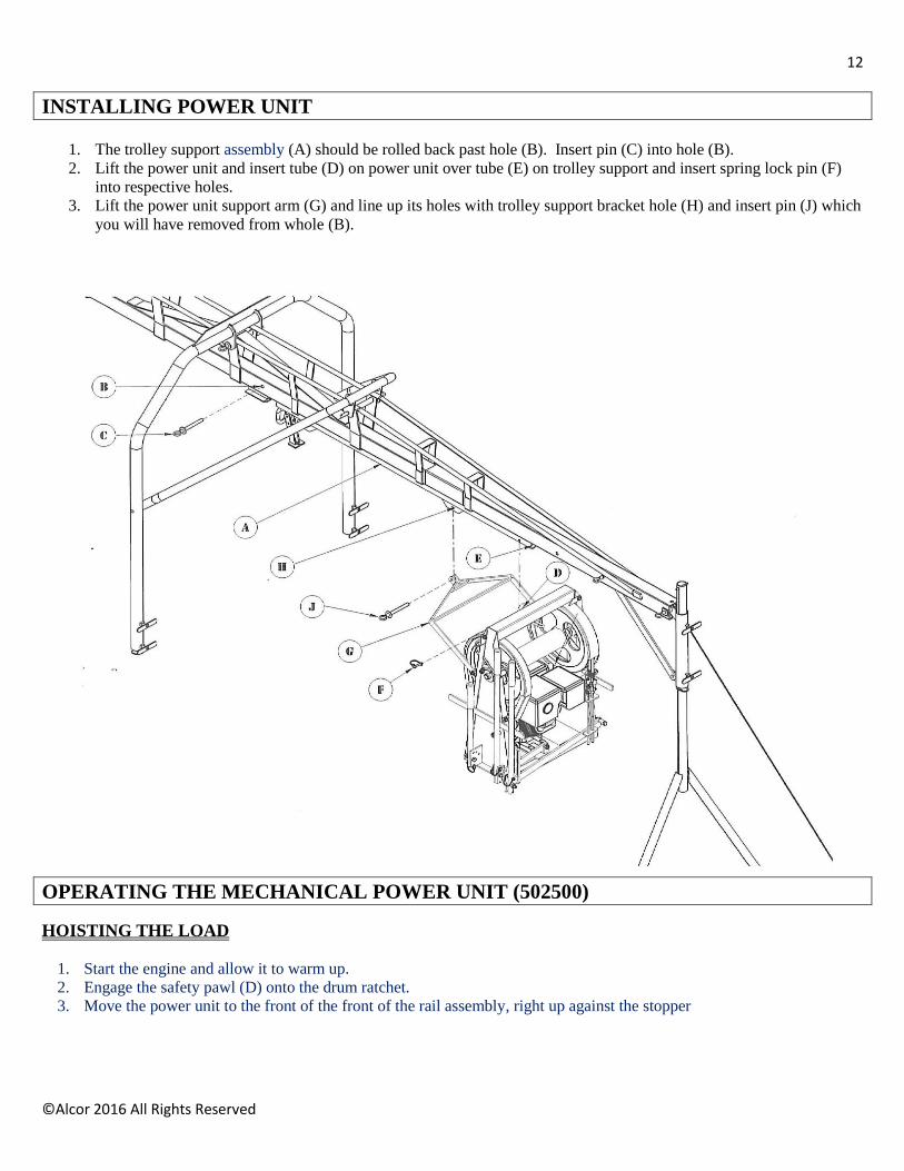
INSTALLING POWER UNIT
1. The trolley support assembly (A) should be rolled back past hole (B). Insert pin (C) into hole (B).
2. Lift the power unit and insert tube (D) on power unit over tube (E) on trolley support and insert spring lock pin (F)
into respective holes.
3. Lift the power unit support arm (G) and line up its holes with trolley support bracket hole (H) and insert pin (J) which
you will have removed from whole (B).
OPERATING THE MECHANICAL POWER UNIT (502500)
HOISTING THE LOAD
1. Start the engine and allow it to warm up.
2. Engage the safety pawl (D) onto the drum ratchet.
3. Move the power unit to the front of the front of the rail assembly, right up against the stopper

13
©Alcor 2016 All Rights Reserved
4. Increase the engine speed to desired level.
5. Raise the clutch handle (B) and brake handle (A) at the same time.
6. When the load is at the desired height, release the clutch handle and brake handle at the same time, this will stop and
hold the load.
7. Pull the load onto the roof by using the stabilizer arm (C).
8. To lower the load onto the roof top, you must disengage the pawl (D).
LOWERING THE LOAD
1. Disengage the pawl. (D).
CAUTION; NEVER ENGAGE THE SAFETY LATCH WHILE LOWERING A LOAD
2. Move the power unit to the front of the rail assembly, right up against the stopper
3. Raise the brake handle (A) slowly until the load is lowering at the desired speed. Speed can be varied by raising or
lowering the brake handle.
CAUTION; LOWER THE LOAD SLOWLY SO IT IS KEPT UNDER CONTROL AT ALL TIMES.
WARNING; AVOID SHOCK LOADS
Do not “jam” on the brake lever. This will cause a severe shock load which can result in equipment damage or personal
injury.
CAUTION; RAISE AND LOWER LOADS SMOOTHLY, AVOIDING SUDDEN STARTS AND STOPS.
MAKE SURE THE TROLLEY RAIL ASSEMBLY IS SEATED AGAINST THE STOPPER AT THE FRONT END
OF THE RAIL, THIS WILL ENSURE THAT THE POWER UNIT IS IN ITS WORKING POSITION RIGHT
UNDER THE POWER UNIT STOPPER ON THE RAIL ASSEMBLY. THIS STOPPER KEEPS THE POWER
UNIT FROM PIVOTING WHEN FORCE IS APPLIED TO THE CLUTCH AND OR BRAKE LEVER.
NOT POSITIONING THE POWER UNIT CORRECTLY WILL RESULT IN OPERATOR FATIGUE AND
DAMAGE TO CLUTCH AND BRAKE COMPONENTS
14
©Alcor 2016 All Rights Reserved
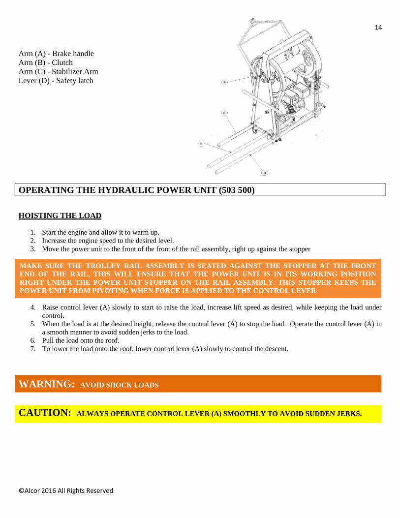
Arm (A) - Brake handle
Arm (B) - Clutch
Arm (C) - Stabilizer Arm
Lever (D) - Safety latch
OPERATING THE HYDRAULIC POWER UNIT (503 500)
HOISTING THE LOAD
1. Start the engine and allow it to warm up.
2. Increase the engine speed to the desired level.
3. Move the power unit to the front of the front of the rail assembly, right up against the stopper
4. Raise control lever (A) slowly to start to raise the load, increase lift speed as desired, while keeping the load under
control.
5. When the load is at the desired height, release the control lever (A) to stop the load. Operate the control lever (A) in
a smooth manner to avoid sudden jerks to the load.
6. Pull the load onto the roof.
7. To lower the load onto the roof, lower control lever (A) slowly to control the descent.
WARNING: AVOID SHOCK LOADS
CAUTION: ALWAYS OPERATE CONTROL LEVER (A) SMOOTHLY TO AVOID SUDDEN JERKS.
MAKE SURE THE TROLLEY RAIL ASSEMBLY IS SEATED AGAINST THE STOPPER AT THE FRONT
END OF THE RAIL, THIS WILL ENSURE THAT THE POWER UNIT IS IN ITS WORKING POSITION
RIGHT UNDER THE POWER UNIT STOPPER ON THE RAIL ASSEMBLY. THIS STOPPER KEEPS THE
POWER UNIT FROM PIVOTING WHEN FORCE IS APPLIED TO THE CONTROL LEVER

15
©Alcor 2016 All Rights Reserved
LOWERING THE LOAD
1. Move the power unit to the front of the rail assembly, right up against the stopper
2. Lower the control lever (A). The load will descend at a controlled speed, the more you lower control lever (A) the
faster the descent.
3. Decrease the speed of the descent as you get closer to the ground.
CAUTION: LOWER THE LOAD SLOWLY SO IT IS KEPT UNDER CONTROL AT ALL TIMES.
Control lever (A) – For raising and lowering
G; AVOID SHOCK LOADS

16
©Alcor 2016 All Rights Reserved
SAFETY HAZARDS
Safety hazards are not always obvious to workers. Unlike exposure to health hazards, where illness or injury develops
slowly, safety hazards usually result in immediate injury or death.
Broken bones, cuts bruises, sprains, burns and loss of limbs, eyesight and hearing are the kinds of injuries caused by safety
hazards.
The rate of occupational injuries in roofing, in fact, ranks in the top ten of all major occupational groups.
Falls
Falls are the number one cause of serious injury and death to roofers. An estimated 10 percent of all roofing accidents result
from falls off roof edges, through roofing openings or off ladders, more than half of the non-fatal accidents result in serious
injury.
Unprotected and unguarded roof edges and roof openings create extremely hazardous conditions.
Ladders with cracked, loose or missing steps: with side rails broken or cracked and not attached firmly to the steps; with
broken, loose or missing locks, or coated with grease, oils or hardened bitumen can lead to serious injury. Ladders should
always be inspected to make sure they’re properly maintained and constructed and that they’re long enough to extend three
feet above the roof’s surface.
Improperly balanced or unstable hoists overturn and will often carry the worker along. Rolls of roofing felt should never be
used as counterweight. Workers should know the load capacity; it should be posted.
Burns
Skin contact with hot asphalt and hot coal tar pitch usually results in second and third degree burns. They usually involve
deeper portions of the skin and are easily infected.
An estimated 16 percent of all injuries are burns from hot stuff. The major causes of burns have been from:
Kettle flashes
Kettle splashes from dropping pieces of coal pitch or asphalt into the kettle
Slips and trips while carrying hot bitumen in open containers
Splashes involving transfer operations like from the hot pipe outlet to a hot lugger, from a hot lugger to a mop
cart or a pail, or from the kettle to a pail.
Heavy Lifting Sprains and strains, a majority of which involve the back, are the most common roofing injury and one of the most severe.
Almost 30 percent of these injuries result in 10 or more days away from work.

17
©Alcor 2016 All Rights Reserved
Fire/Explosion Two conditions must be met in order for fires and explosions to occur. First, there must be an ignition source, a welding arc,
spark, cigarette, flame or simply a hot spot as in a kettle or tanker. Secondly, there must be the right mixture of vapours
(from asphalt, pitch, solvents) and oxygen.
For kettles and tankers, fire/explosion conditions arise when:
oversized burners are used to fire the kettle, causing localized overheating of the heating tubes creating a hot spot
the temperature of the bitumen is brought up to the desired operation temperature too quickly allowing the level
of bitumen to drop to the level of the firing tubes, allowing excessively high surface temperatures
heating the bitumen to its flash point (for asphalt, about 525°-540°; for pitch, about 450°-475°)
the temperature of the bitumen is hot enough to reach the auto-ignition level
in tankers, the vent pipe is clogged or plugged so that flammable vapours can build up to explosive levels
Many solvents evaporate quickly at roof temperatures. Explosive mixtures of vapours can be readily formed within confined
spaces like high parapet walls, in atriums or in any space where little or no ventilation exists. And any kind of spark or flame
can ignite the vapours.
Electrocution Low voltage electricity can cause shock, muscle contractions, breathing difficulty, irregular heartbeat, severe burns and death.
The route that the current takes through the body affects the degree of injury. Current flowing from one finger to another
would not pass vital organ, while from one hand to another would pass through the heart and lungs.
Electrical tools should be properly grounded. The electrical cord should end in a three-prong grounding contact, or the wires
should be enclosed in a metal case with a special grounding attachment.
Employers are required to provide ground fault circuit interrupters for all outlets on construction sites that are not part of the
permanent wiring of the building. This is actually a fast-acting circuit breaker, which can shut off electricity in a fraction of a
second.
Aluminum or other metal ladders pose a serious electrical hazard around electrical equipment and energized lines.
Falling Objects Tools, bricks, materials, buckets, boxes, pallets or almost anything dropped from a sufficient height can cause severe damage.
Head injuries, one of the highest compensated injuries to workers, often include brain damage.
Workers need protective head gear when working beneath people, tools and equipment.
Flying Objects Objects can be projected by machines, from welding or grinding operations and can be windblown. Tear-off operations,
where power cutters, power brooms and power spudders are generally used, are the major source of flying substances.
The part of the body most often injured is the eyes.
Unguarded Machinery Exposed blades and chains on powered machinery like hoists and roof cutters can severely lacerate and crush parts of the
body. Guards should always be fitted over moving parts to protect workers.