GridPro v6
153
Program Development Company © 2016 Grid Pro v6.5
Transcript of GridPro v6

Program Development Company © 2016
GridPro v6.5

Program Development Company © 2016
Introduction to UI
Empty Space referred as drawing space
Top Menu bar
Global Dock
Workplane toolbar
Status Bar Toggle Surface Section
Right side toolbar

Program Development Company © 2016
Graphics User Interface
The GridPro GUI is divided into five tabs such as
Only right side toolbar varies in all tabs

Program Development Company © 2016
Graphics User Interface
Opening the GUI
Windows Users-Double click icon available in the desktop.
Linux or MAC users, Open a terminal, type ws and press return(enter).
Setting the working directory:
Go to File menu .
Select the Working directory option.
Navigate the path to specified directory and
click on select folder button

Program Development Company © 2016
New Workspace:
Click on the New button to create an empty workspace.
Select the appropriate dimension from the drop down list.

Program Development Company © 2016
Global Dock
New Workspace
Save Topology and Grid
Delete Topology, surface and grid entities
Load Topology, Surface/s
and Grid
Undo and Redo
topology creation
step
Zoom-in and Zoom-Out
Topology And Grid Information
Frame the Screen to Topology/ Surfaces

Program Development Company © 2016
Global Dock
Pick Centre of Rotation
Show all the surfaces
Show only current surface
Change the surface/grid display type
Display type for all surfaces
Display type for all
surfaces while panning
Display type for current surface
Snap the screen axis
Select surface

Program Development Company © 2016
Global DockToggle Wireframe,
Surfaces, Workplane,
Grids and Geometry
Start Ggrid
Stop Ggrid
Check Topology
validity
Geometry Display options

Program Development Company © 2016
Surface Formats
• GridPro deals with 3 kinds of surfaces.
Linear surfaces (dat, lin)- Can be imported or created in GridPro.
Triangles (tria) - Created from imported stl geometry.
Quads (quad) - Can be imported or created in GridPro
• Analytical surfaces defined by GridPro are
2D 3D
Line Plane
Circle Cylinder
Ellipse Ellipsoid
Periodic Periodic
Other surface that is dealt with GridPro - Tube
Linear
Tria
Quad

Program Development Company © 2016
Analytical Surfaces
The analytical surfaces can be created in the GridPro GUI

Program Development Company © 2016
Analytical Surfaces
The analytical surfaces can be created in the GridPro GUI
Automatically calculates the
workplane position and enter
the required information in the
respective fields
Ok – Creates the
surface and
closes the dialog
box
Cancel – Closes the dialog
box without any changes in
the UI
Apply– Creates the surface
and keeps the dialog box
open

Program Development Company © 2016
Contd…
Power – Determines the Shape of the
surface. If the power is >2, it creates a
super ellipsoid or super cylinderLength dir – Axis along
the length of the cylinder
Surface which define the
translational symmetry/periodicity
of the given geometry
Rotational symmetric surface – Surface
which define the rotational
symmetry/periodicity of the given geometry

Program Development Company © 2016
Contd…
Sphere Ellipsoid
Cylinder
Circle Ellipse
Xpolar
XYZ
NOTE: Sphere is a special case of Ellipsoid

Program Development Company © 2016
CURRENT Surface
• In GridPro, effect of functions related to surfaces, are
performed on the single selected surface which is referred
as CURRENT SURFACE.
• Current surface is always seen in sea blue color.
• By default, when any geometry or topology is loaded, the
last surface which has been read by GridPro is set as
Current Surface.Current surface

Program Development Company © 2016
Toggle Surfaces
• All surfaces loaded into GUI have an id starting from 0, which is referred as surface id.
Current surface id. As one scroll through surfaces, the
id of current surface will be changed and so is current
surface color will be shifted from one surface to next.
Backward scroll – Make
previous surface as
currentForward scroll – Make
next surface as current
Show/Hide the current
surface
Toggle surface section
Surface id: 0
Surface id: 1

Program Development Company © 2016
Contd…
Shows all the surfaces loaded in the UI.
Any surfaces which are hidden before
this operation either using button or
using the ‘Hide’ option in the right click
menu of surfaces will be made visible.
Shows only the current surface in
the UI. Any number of surfaces can
be made visible after this operation
using the button.
Pick a surface to be current.
Click on this button and click on
the desired surface to make it as
current
Display mode for the
surfaces
Toggle surface section

Program Development Company © 2016
Surface Display Types
Surfaces, geometries and grid can be viewed in various modes for better visualization.
Displays the selected mode for ALL surface. Default:
Shaded for 3D, Lines for 2D
Displays the selected mode for only CURRENT
surface. Default: Shaded for 3D, Lines for 2D
Displays the selected mode for ALL surfaces while
MOVING/PANNING the screen. Default: 1/10th of
original points for both 2D and 3D
Resets all the display modes to
DEFAULT
Display button in Global dockPolygon faces of the object are drawn using the object’s
own color but the polygon boundaries (edges) are drawn
in white.
Only polygon faces of the object are drawn, using object’s
own color
Polygon faces of the object are drawn using the
background color and the polygon boundaries (edges) are
drawn using object’s own color.
Only polygon boundaries (edges) are drawn, using
object’s own color.
Only the polygon vertices are displayed
Displays only 1/10th of all the polygon vertices.

Program Development Company © 2016
Right Click Menu for Surface
Hides the selected surface
Displays Surface
Information
Picks the location as center
of rotation
Makes the selected surface as
“CURRENT” surface
Deletes the selected surface
Changes the orientation of
surface
Transforms the selected surface
Changes the display type for
selected surface
Sets property to the
surface
Opens surface definition
dialog box

Program Development Company © 2016
Gridding Process
Surface Wireframe Assignment Grid
Creating Wireframe
Loading the geometryAssigning respective
wireframe sheets to
respective surfaces
Generating grid
Visualizing Grid

Program Development Company © 2016
Topology Terminologies
Topology
Wireframe
Block
Faces
Edges Corners
Surfaces
Corner is defined as a
point in space which is
represented as ordered pair
of numbers ( x, y, z ) where
x, y, z is the coordinates of
the point in x, y, z axis
respectively
An edge is a line segment joining two
adjacent vertices in a face.
A face is a closed
sequence of edges.
Exactly two faces
meet at every edge
of a block.

Program Development Company © 2016
Topology Terminologies
Topology
Wireframe
Block
Faces
Edges Corners
Surfaces
Collection of blocks linked together to
form a wireframe. In a wireframe,
there are more faces meet at an edge.
A block is a closed
sequence of faces.
Program Development Company © 2016
Topology Terminologies
Topology
Wireframe
Block
Faces
Edges Corners
Surfaces
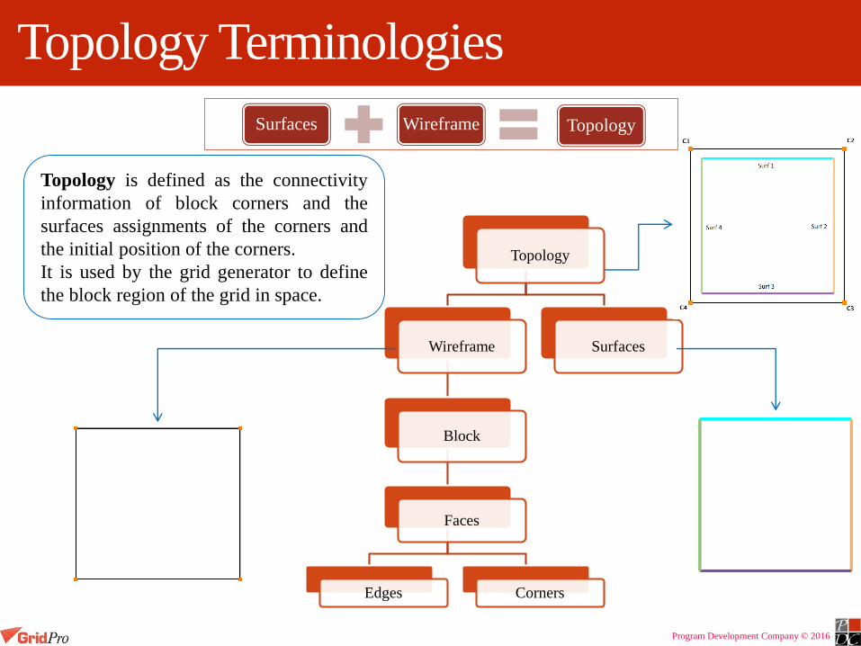
Topology is defined as the connectivity
information of block corners and the
surfaces assignments of the corners and
the initial position of the corners.
It is used by the grid generator to define
the block region of the grid in space.
Surfaces Wireframe Topology

Program Development Company © 2016
Surface Assignments
GridPro grid generator projects the block edges automatically on the surfaces
To establish a relation between surfaces and wireframe, corners are assigned or associated to surfaces.
This association helps in projection of corners on surfaces.
Surfaces Corners
Surf 1 C1, C2
Surf 2 C2, C3
Surf 3 C3, C4
Surf 4 C4, C1
After Projection
Triple Assigned
Corner
Double Assigned Corner

Program Development Company © 2016
Surface Assignment Rules
1. If three or more blocks are emerging from an edge in 3D (or corner in 2D), it cannot be assigned to a boundary surface.
Incorrect Assignment
Correct Assignment

Program Development Company © 2016
Surface Assignment Rules
2. Two edges/faces of a same block cannot be assigned/associated to a single surface.
Incorrect Assignment Correct Assignment

Program Development Company © 2016
Surface Assignment Rules
3. The corners/edges which are only assigned to an internal surface should share two blocks on either side.
Incorrect Assignment Correct Assignment

Program Development Company © 2016
Surface Assignment Rules
4. The slope discontinuity in a single surface should be represented with two distinct surfaces.

Program Development Company © 2016
Surface Assignment Rules
5. When the surface slope discontinuity is convex in nature, the blocks emerging out of an edge (or corner in 2D) should be 2 and if it is concave in nature, the blocks emerging out of an edge (or corner in 2D) should be 1.
Incorrect TopologyCorrect Topology
Program Development Company © 2016
Surface Groups
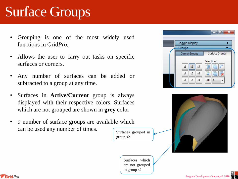
• Grouping is one of the most widely used
functions in GridPro.
• Allows the user to carry out tasks on specific
surfaces or corners.
• Any number of surfaces can be added or
subtracted to a group at any time.
• Surfaces in Active/Current group is always
displayed with their respective colors, Surfaces
which are not grouped are shown in grey color
• 9 number of surface groups are available which
can be used any number of times.Surfaces grouped in
group s2
Surfaces which
are not grouped
in group s2

Program Development Company © 2016
Contd…
Add/subtract surfaces one by one by clicking on
them.
Add multiple surfaces by dragging a box with right
mouse button. Surface which are partially dragged
are also added.
Subtract surfaces from the active group by dragging
a box with right mouse button. Surfaces which are
partially dragged are also subtracted.
Retain surfaces which are selected from the active
group by dragging a box with right mouse button.
Surfaces which are not in the group will not be
added even if it is dragged.
Add the selected surfaces or selected group
Remove all the surfaces grouped in the active
group.
Group which is having all the surfaces already
grouped in it.
Display mode for the surface group.

Program Development Company © 2016
Add a Group from another Group
The groups section acts as a calculator such that one group can be added, subtract or intersected with
another group
Example: Add Group s2 surfaces to Group s1
Step 1: Click on Group s1 to make it active.
Step 2: Click on the button
Step 3: Click on Group s2
=
Group s1 Group s2 Resulted Group s1

Program Development Company © 2016
Subtract a Group from another Group
Step 1: Click on Group s1 to make it active
Step 2: Click on the button
Step 3: Click on Group s2
=
Group s1 Group s2 Resulted Group s1
Example: Subtract Group s2 surfaces from Group s1
Program Development Company © 2016
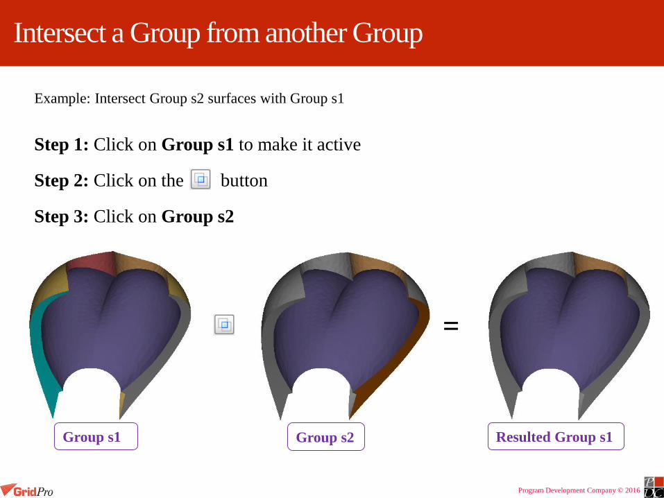
Intersect a Group from another Group
Step 1: Click on Group s1 to make it active
Step 2: Click on the button
Step 3: Click on Group s2
=
Group s1 Group s2 Resulted Group s1
Example: Intersect Group s2 surfaces with Group s1

Program Development Company © 2016
Add/subtract two groups to a new group
Step 1: Click on Group s1 to make it active
Step 2: Click on the button
Step 3: Click on Group s2
Step 4: Click on the button
Step 5: Click on Group s3
Example: Adding group s2 and group s3 to group s1(Initially empty)
Group s3Group s2Resulted Group s1
=
Add or subtract two groups and
result the output in the new group

Program Development Company © 2016
Corner Groups
Similar to surface groups, corner groups allows the user to carry out tasks on specific parts of the topology
Any number of points and edges of the topology can be added or subtracted to a group at any time
Active group is always in bright yellow, inactive topology is always shaded dark.

Program Development Company © 2016
Adding or Subtracting Topology to a Group
•Click on a group button
•Click on ( ) button and draw a box with right mousebutton around the topology.
•To subtract topology from a group click on ( ) buttonand draw a box around topology
•All topology can be emptied from a group by clickingon ( )
•Can add topology points and edges individually byclicking on the ( ) button and choosing each pointwith the left mouse button
1 2
3

Program Development Company © 2016
Add a Group from another Group
• Grouping functions act as a calculator such that one group can be added,
subtract or intersected with another group
Example: Add Group 2 topology to Group 1
Step 1: Click on Group 1 to make it active
Step 2: Click on the ( ) button
Step 3: Click on Group 2
+ =
Group 1 Group 2

Program Development Company © 2016
Intersection of a Group from another Group
Step 1: Click on Group 1 to make it active
Step 2: Click on the (*) button in the TOPO Menu
Step 3: Click on Group 2
Group 1 Group 2
* =

Program Development Company © 2016
S group
• Group always contains the corners assigned to the current surface.
• If the current surface is changed, the corners in this group will get changed instantly.
• Hence it’s called surface assignment group or S group.
• It can be used to add the surface assignments corners of the current surface to any
group.
• Any other selection operations can not be done on this group.

Program Development Company © 2016
Group Mode
• Different display modes helps in better visualization of the wireframe as well as
effective way of using certain functions.
Displays both active and inactive corners
in the UI. Displays only active corners in the UI. I.e.
the corners in the current corner group
• Reference group. Each group from R-1 to R-9 represents the corner groups c1 to c9 respectively.
• Similar to ‘A’ where the active corner group is highlighted with respect to all other inactive corners. In
reference mode, An active corner group can be seen with respect to a particular corner group which is called
as reference group(inactive).
• Display the corner group which is switched on as active and the corner group which is selected here as
inactive.

Program Development Company © 2016
Contd…
‘A’ mode when no group is active
‘A’ mode when group c3 is active
‘G’ mode when group c3 is active‘R3’ mode when group c6 is active

Program Development Company © 2016
Workplane
• Workplane is primarily used to create topology.
• It is an infinite plane in space but shows as
finite plane for visualizing purpose.
• It is represented in purple color with four nodes
on the corners which helps in resizing the
workplane.
• It contains its own axis and can be rotated and
translated anywhere in the screen in any
direction.
• The left side of the UI is dedicated to the
workplane related tools.
• Each axis is represented with an color similar
to the global axes. i.e. Pink for X axis, Green
for Y axis and Blue for Z axis.Axis/Handles
Node
Workplane
X
Y
Z

Program Development Company © 2016
Contd…
Snaps the workplane to world/screen X, Y and
Z axis
Fits the workplane to the center of mass
of the given wireframe
Snaps the workplane to the screen z
axis always Pick the center of workplane on any object
(surface, corner, edge, grid blocks and grid
sheets)
Shade the workplane with translucent
white for better visual aid when the
surface is clipped.
Clips any one normal side of the surface/grid
for viewing inside objects of the surface.
Show/Hide the axis of the workplane.

Program Development Company © 2016
Click on the
Y axis to
make it as
rotation axis
Workplane Handles
To move the workplane,
Click and drag any axis with left mouse button to move the workplane along that
axis.
The pointer will change to curved arrows once you hover it on the workplane axis
which indicates that the axis can be rotated/translated.
To rotate the workplane,
Click on the axis about which the workplane has to be rotated with the left mouse
button.
The selected axis will become thinner than other two indicating the rotating axis.
Next click on any of the other two axis with middle mouse button to rotate the
workplane about the selected axis. Rotate
about Y axis

Program Development Company © 2016
Position the Workplane
The workplane can be positioned based on three different ways apart from
the manual translation.
1. By picking an object
2. Based on screen axis
3. Based on wireframe

Program Development Company © 2016
Picking an Object
• Position the workplane to a desired location with a click of a button.
Select the button and click on any object such as surface, corner, edge or
grid to position the work-plane center to the picked location.
Workplane positioned on a
surfaceWorkplane positioned on a
corner
Workplane positioned on an
edge
Program Development Company © 2016
Position – Screen axis
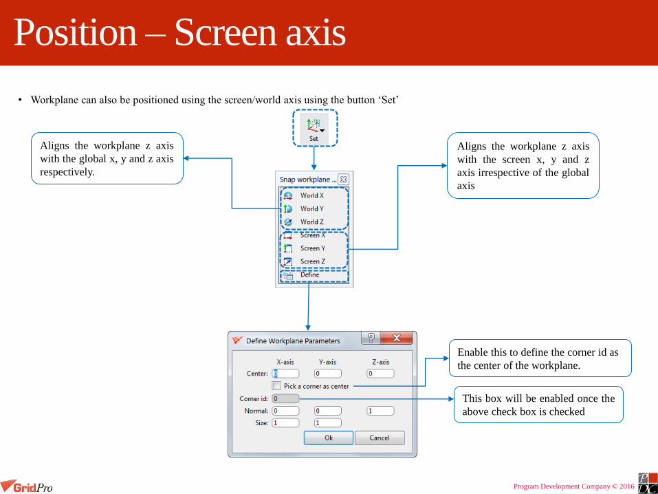
• Workplane can also be positioned using the screen/world axis using the button ‘Set’
Aligns the workplane z axis
with the global x, y and z axis
respectively.
Aligns the workplane z axis
with the screen x, y and z
axis irrespective of the global
axis
Enable this to define the corner id as
the center of the workplane.
This box will be enabled once the
above check box is checked

Program Development Company © 2016
Position – Wireframe
• Workplane can also be positioned with respect to a corner group.
• Positions the workplane center with the center of mass of the active corner group
• Three different axis positions are available.
Aligns the workplane normal axis to the
shortest major group axis and the other two
workplane axes to the other two group axes.
Aligns the workplane normal axis to the second
shortest major group axis and the other two
workplane axes to the other two group axes.
Aligns the work-plane normal axis to the
longest major group axis and the other
two work-plane axes to the other two
group axes.

Program Development Company © 2016
Corner
Corner creation is basic topology creation tool.
It can be created by two ways by positioning the cursor or by specifying the co-ordinates
A corner can be placed on surface or on workplane on the basis of mode selected

Program Development Company © 2016
Link
To form a block, you need to link the created corners.
Linking can be done by
Either by picking up corners one-by-one
Either by dragging box around group of corners to be linked
Either dragging box on two groups of corners one by one which needs to be linked
Or by specifying the corner group numbers which need s to be linked

Program Development Company © 2016
LinkLinking corners by picking one by one

Program Development Company © 2016
Link
Linking corners by dragging box around the group of corners need to be linked
Linking corners by dragging box one by one on group of corners need to be linked

Program Development Company © 2016
Link
Linking by specifying the groups which needs to be linked
Group 1 Group 2
Input
Output
Operation

Program Development Company © 2016
InsertBy using insert you can add faces in the existing blocks and splitting a block into two.
Insert is done in three ways
Based on propagation method – ALL, Group, Single edge
Density based
No. of faces required

Program Development Company © 2016
Insert Based on Propagation
Propagation through All Propagate only to group Propagate to Only edge

Program Development Company © 2016
Insert Based on Density
Current edge density is 8
If base density is specified as 2, it will create 2 more inserts so that each edge in that corner group will have edge density as 2
InputOutput

Program Development Company © 2016
Insert Based on no. of FacesRight click menu of an edge gives you an option to do multi-insert
Based n the no. of sheets provided, it will insert

Program Development Company © 2016
Wrap
• In GridPro, wrap is used to create an O-grid.
• A wrap is an extrusion of the topology outward or inward, the ratio being specified by the user.
*Will be explained
later
Intelliwrap: Surface assignments of the corners used
for wrap if any, will be moved to the wrapped
corners.
Carry assignment: Surface assignments of the
corners used for wrap if any, will be copied
to the wrapped corners.
No assignment: Surface assignments of the corners
used for wrap if any, will NOT be copied/moved
to the wrapped corners
Wrap the given corners
inside with the given
percentage
Wrap the given corners
outside with the given
percentage
The edge distance/distance between
the corners used for wrap and the
wrapped corners in terms of
percentage

Program Development Company © 2016
Exercise
Open the Circle exercise directory
Load circle.fra file into the UI
Group all the corners to a group
Wrap it inside with 20% ratio with No
assignment.

Program Development Company © 2016
A key
• Easiest way to group a sheet of corners.
• Group a cross sectional sheet which propagates through the whole topology.
• An identical blocking pattern should exist adjacent to the normal side of the selected edge.
• It can be used along with and button to add or subtract sheets to/from the active corner group.
Group a few corners along with
corners of the desired layer
Hold the A key and click on the edge close to the corner
as shown
A sheet of corners will be grouped if it has corners linked one to one adjacent to it

Program Development Company © 2016
Contd…

Program Development Company © 2016
Span out/Peel off
• Add or remove sheets of corners from active group by using span out or
peel off button
• It will not work if the reference mode is in ‘G’.
Span out 1 layer Span out 2 layer Span out 3 layer
Peel off 2 layer

Program Development Company © 2016
Backup Groups
• A function which keeps saving the corners which are used in
the previous operation.
• It can be retrieved under any corner group.
• Only the corners which are used in the current session can be
retrieved.
• Each time it is clicked, the corners which are last operated to
the existing one will be retrieved.
• Main application is to assign the corners easily after wrap.
• Works similar to Undo/Redo
Retrieves the
last operated
corners
Retrieves the
previously
retrieved corner
group

Program Development Company © 2016
Contd…
Group 3 after wrap Group 3 after using
backup group button onceGroup 3 after using
backup group button
twice
Group 3 before wrap
Group 3 after using
forward group button
once
Group 3 after using
forward group button
twice
No more
forward
group to
retrieve
No more backup group
to be retrieve

Program Development Company © 2016
Exercise
Open the Circle exercise directory
Load circle_bg.fra file into the UI
Add all the corners in a group
Wrap the corners outside with 10%
ratio
Use backup group to get the wrapped
layer
Assign it and run the gridding process
to get the grid

Program Development Company © 2016
Merge
To merge using screen select first
define the position of the merged
corners then drag two boxes either
on individual or group of corners
needs to be merged
Place the corners need to be
merged in different corner
groups and define the corner
groups based upon the
position
Merge using Screen Select Merge using Groups

Program Development Company © 2016
Merge by screen selecting individual corner
Merge to Center
Merge to Selection 1
Merge to Selection 2
Select First corner Select Second corner

Program Development Company © 2016
Merging by screen selecting group of corners
Merge to Center
Merge to Selection 1
Merge to Selection 2
Select first set of corners Select second set of corners

Program Development Company © 2016
Merge by Specifying Groups
Group 1
Group 2
Input
Merge to
Center
Merge to group
2 position
Merge to group
1 position

Program Development Company © 2016
Merging Disjoint Topology
Merge to
Center
Merge to
selection1
Merge to
selection 2

Program Development Company © 2016
Move Topology
Move using workplane or using pointer Move using coordinates
• Move a corner / active corner group,
Parallel to workplane
Normal to workplane
Parallel to surface
Normal to surface
• Corners can be moved either on workplane or on surface.
• It can be either moved parallel or normal to the either one of the object.
• One option in each would be selected.
• By default, the corners are moved parallel to workplane.
• To move a single corner, drag the corner wherever necessary using left
mouse button. Move button need not be used unless the move options need
to be changed.
• Move a corner/ active corner group by entering the
desire location.
• In case of active corner group, the center of mass
of the group will be moved to the desired location.

Program Development Company © 2016
Copy
It allows you to copy group of corners to workplane position based upon the mode selected
Copy with links places the
centre of mass of group of
corners on centre of
workplane position and link
the group of corners to
given group of corners
Though workplane is in slanted position,
corners position is same

Program Development Company © 2016
Copy with Links & Projection
Copy with Links and
Projection first project the
group of corners onto
workplane then copy it with
links to given group
Here orientation of workplane
is considered. There is change
in corners position compared
to only “Copy with Links”
operation

Program Development Company © 2016
Copy with no Links only
Copy with no Links only copy
corners position to workplane
position without linking to
original corners
For this also orientation
o workplane does not
matter. It’s behaviour is
similar to Copy with
Links operation
Program Development Company © 2016
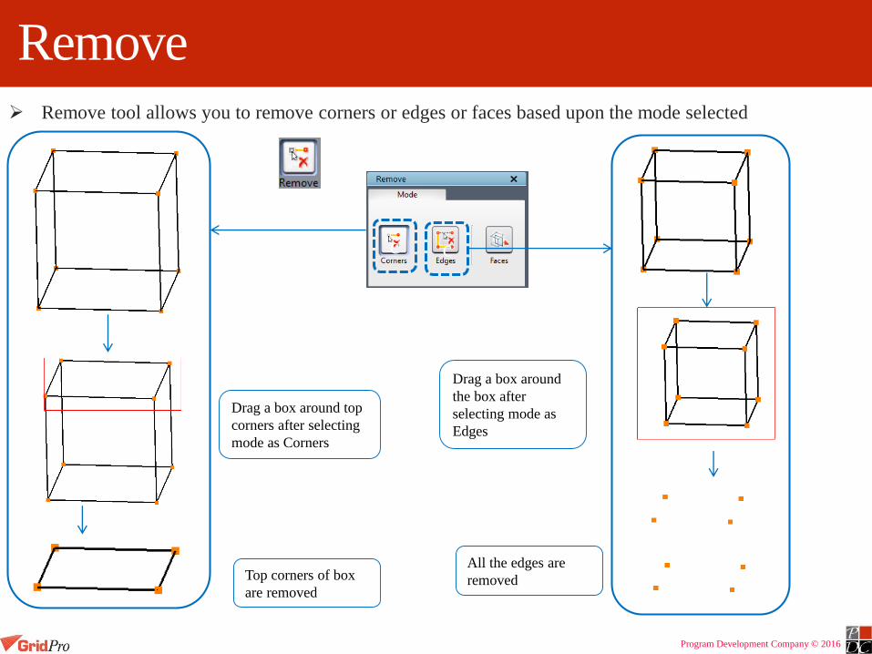
Remove Remove tool allows you to remove corners or edges or faces based upon the mode selected
Drag a box around top
corners after selecting
mode as Corners
Top corners of box
are removed
c
Drag a box around
the box after
selecting mode as
Edges
All the edges are
removed
c
Program Development Company © 2016
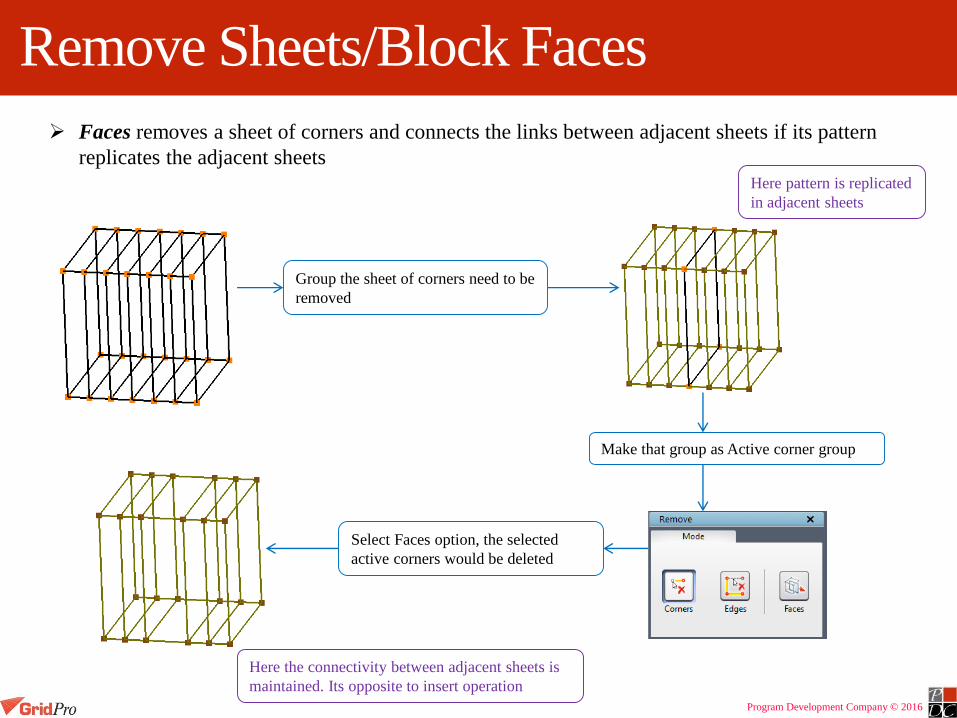
Remove Sheets/Block Faces
Faces removes a sheet of corners and connects the links between adjacent sheets if its pattern
replicates the adjacent sheets
Make that group as Active corner group
Here pattern is replicated
in adjacent sheets
Group the sheet of corners need to be
removed
Select Faces option, the selected
active corners would be deleted
Here the connectivity between adjacent sheets is
maintained. Its opposite to insert operation
Program Development Company © 2016
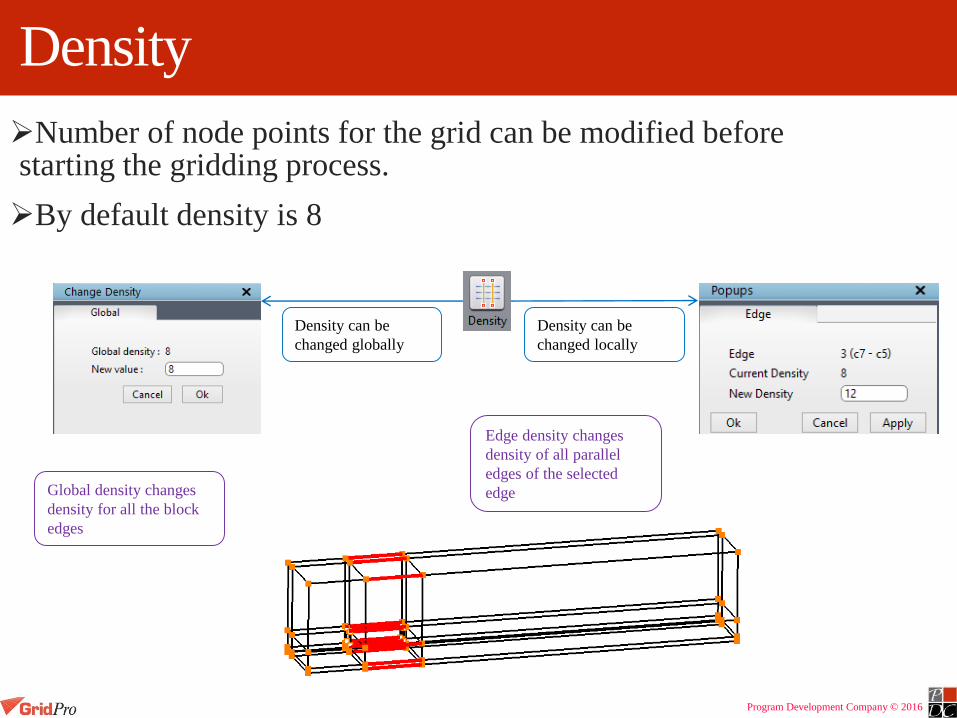
Density
Number of node points for the grid can be modified before starting the gridding process.
By default density is 8
Density can be
changed globally
Density can be
changed locally
Global density changes
density for all the block
edges
Edge density changes
density of all parallel
edges of the selected
edge
Program Development Company © 2016
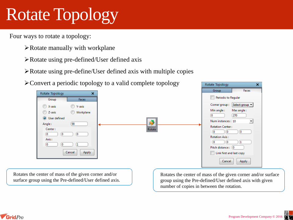
Rotate TopologyFour ways to rotate a topology:
Rotate manually with workplane
Rotate using pre-defined/User defined axis
Rotate using pre-define/User defined axis with multiple copies
Convert a periodic topology to a valid complete topology
Rotates the center of mass of the given corner and/or
surface group using the Pre-defined/User defined axis.Rotates the center of mass of the given corner and/or surface
group using the Pre-defined/User defined axis with given
number of copies in between the rotation.

Program Development Company © 2016
Rotate Topology with Workplane
5. Click on the desired axis of rotation in the workplane.
6. Rotate the other workplane axis with the middle mouse
about the selected axis of rotation.
1. Group the corners to be rotated. 2. Fit the workplane to the grouped corners
using Fit 1.
3. Click on the Move button.
4. Switch on the handles of the workplane.

Program Development Company © 2016
Rotate Topology with Defined Axis
1. Group the corners to be rotated.2. Enter the necessary inputs
After rotation about X axis
After rotation about Y axis
After rotation about Z axis

Program Development Company © 2016
Rotate with Multiple Copies
1. Create the necessary
wireframe
2. Group the corners
3. Enter the Inputs.
For this case, the
center of the
geometry is origin
and the rotational
axis Z axis.
NOTE: Providing
pitch distance
greater than zero
will rotate the
wireframe helically
4. After rotationNo. of instances created = 30

Program Development Company © 2016
Periodic Topology to Complete Topology
Periodic topology with periodicity 60 degree Check the Periodic to Regular check box
Click ‘Ok’ to proceed
Complete topology created along with
the surface from the periodic topology
Program Development Company © 2016
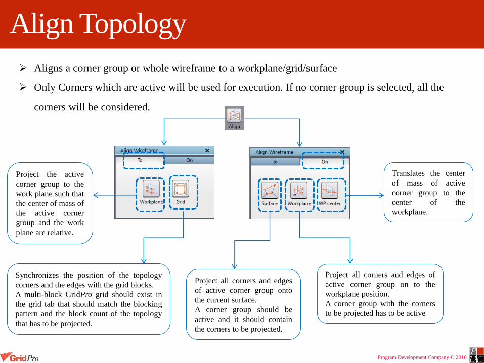
Align Topology
Aligns a corner group or whole wireframe to a workplane/grid/surface
Only Corners which are active will be used for execution. If no corner group is selected, all the
corners will be considered.
Project the active
corner group to the
work plane such that
the center of mass of
the active corner
group and the work
plane are relative.
Synchronizes the position of the topology
corners and the edges with the grid blocks.
A multi-block GridPro grid should exist in
the grid tab that should match the blocking
pattern and the block count of the topology
that has to be projected.
Project all corners and edges
of active corner group onto
the current surface.
A corner group should be
active and it should contain
the corners to be projected.
Project all corners and edges of
active corner group on to the
workplane position.
A corner group with the corners
to be projected has to be active
Translates the center
of mass of active
corner group to the
center of the
workplane.

Program Development Company © 2016
Enrich Topology
Enriching a specific region of the topology without affecting the farfield.
Adds more topology corners in a complete topology without propagating to the
farfield.
Special case of internal wrap
Corner group c3 used for refinement
After refinement

Program Development Company © 2016
Surface Assignments
Assigned corners will be highlighted with white dots.
Corners can only be assigned to current surface.
Assign corners to
periodic surface only.
Assign corners
individually to current
surface by picking the
corners one by one
Assign multiple corners to
current surface by dragging a
box with right mouse button.
Remove the surface
assignments from the
corners.
Displays only the surface
assignment corners of the current
surface in the UI
Remove the surface
assignments from the corners
by dragging a box with right
mouse button.
Remove all the
surface assignments
of the current surface
with a click of a
button.

Program Development Company © 2016
Assign corners
Make the desired surface, current. Group the corners to be assigned to the current surface.
Switch on toggle/Add buttonPick the corners/drag the corners with right mouse button

Program Development Company © 2016
Remove surface assignments
Make the desired surface, current , whose surface assignments has to be
removed.
Group the assigned corners
Switch on Remove button
Choose the option ‘screen select’ if you want to remove few of the surface
assignments or ‘Clear’ if you want to remove all of the surface assignments.
If you select, ‘screen select’, select the corners whose surface assignments has to
be removed by dragging a box with right mouse button.

Program Development Company © 2016
Periodic surface assignments
Periodic surface assignments are handled using:
– Specific surface that define the characteristics of the symmetric conditions, called
‘periodic surface’.
– Topology on the periodic boundaries has to be assigned to this surface.
Group the corners on the periodic
boundary either in same group or
different groups. Here it is grouped
in same group.
Switch on the Period button and select
the periodic boundary one by one by
dragging a box with right mouse button
as shown
Once the second periodic boundary
corners are selected, the corners will be
highlighted with white dots as shown.

Program Development Company © 2016
Block Structured Grid
All blocks have 6 faces, 12 edges and 8 vertex
points and can exist in any shape and size
Edges contain the distribution of points in the i, j,
k directions
The blocks of the grid contains edges outlines,
center of mass and skeletons (links from center of
mass to the center of each face)

Program Development Company © 2016
A slice is a grid that cuts through a block.
A face sheet composed of the faces of the outer
boundaries of all outer, activated blocks is called a mesh
Grid Terminologies
Grid with blocks
Faces Sheet
MeshSlice sheet
A grid face is the grid about a boundary of a block.
A sheet is simply a collection of linked faces or a collection of linked slices. A sheet composed of linked faces is called a face sheet, and a sheet composed of linked slices is called a slice sheet.

Program Development Company © 2016
Grid Viewing Tools
Only grid blocks are visible when grid is loaded into UI
Blocks can be turned off by unchecking the box in Blocks tab under Show/Hide section

Program Development Company © 2016
Mesh
A single sheet representing the mesh of the blocks is shown

Program Development Company © 2016
Faces
It shows grid points on all surfaces (boundary and including internal)
If Boundary is selected only
boundary surface grid sheets
will be shown
If Internal is selected all internal
surfaces grid in addition to
boundary surfaces, internal
surface grid sheets will also be
shown

Program Development Company © 2016
Slice
Grid sheets through blocks can be displayed in any i, j, k direction
To display sheet click on the Slice icon
Click on a block edge and sheet is automatically displayed
Grid sheets shown at various cross-section

Program Development Company © 2016
Scrolling between the Sheets
Clicking on particular sheet name will make that sheet as current sheet
Current sheet is highlighted and seen in sea blue colour
Sheet 4 is selected as CURRENT sheet
Sheet 5 is selected as CURRENT sheet
Sheet 8 is selected as CURRENT sheet

Program Development Company © 2016
Scrolling SheetThe grid sheet can be stepped through the block in any i, j, k direction by clicking on the stepbuttons
Only the current sheet (in sea blue) can be scrolled
Stepping current sheet in the grid
block
Current sheet is moved some steps
Current sheet is moved some steps ahead
Sheet 4 as highlighted is Current Sheet

Program Development Company © 2016
Toggling Sheets
By checking or unchecking a box next to grid sheet name show or hide the respective sheet
Here, sheet 5 and sheet 6 are hidden

Program Development Company © 2016
Toggling Sheets
Shows all sheets
Shows only current sheet
Flips the visibility of all sheets
Options are used for grid sheets toggling
Program Development Company © 2016
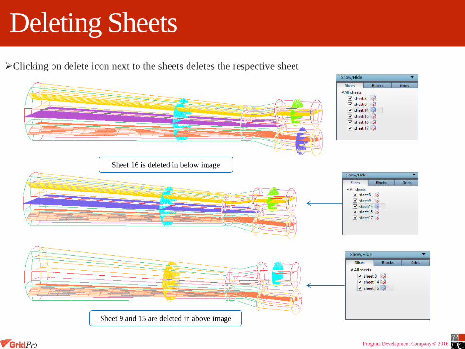
Deleting Sheets
Clicking on delete icon next to the sheets deletes the respective sheet
Sheet 16 is deleted in below image
Sheet 9 and 15 are deleted in above image

Program Development Company © 2016
Colour
Coloured by Block
Coloured by Sheets
Coloured by IJK value
Blocks –Colour varies as grid blocks varies
Sheets- Colour varies as grid sheet varies
IJK- Colour is constant along the co-ordinate
A grid can be coloured on the basis of

Program Development Company © 2016
Reload
If Ggrid is running, there would be some changes in grid file after every time it is written
Click on Reload icon to reload the grid
Grid can be reloaded Manually or Automatically
reloads the grid every time it is
written
allows user to decide when
a grid should be reloaded

Program Development Company © 2016
Viewing GridsTwo grids can be loaded into UI and the user can choose which grid to work upon
Grid which is highlighted is Current grid
All the operations are only performed in Current grid
Checking/unchecking will show or hide the grid
Only one gird is loaded Two grids are loaded
blk_cylinder is CURRENT grid

Program Development Company © 2016
SpacingDistance between two node points can be measured precisely using Spacing option
Allows you to check precisely off-the-wall spacing near a boundary
Click on spacing icon
Click on a node point in current sheet
Click on another node point
It is useful for checking clustering in grid
Distance between these two node
points is measured

Program Development Company © 2016
Trimming Grid BlocksBlocks can be trimmed away
Click on Trim icon
Blocks tab with all the options will open up
Click on icon
Draw a box around the blocks while holding down right mouse button and blocks will be trimmed away
Clicking on icon displays
active grid block skeleton with
centersDrag a around the block centers
which needs to subtracted

Program Development Company © 2016
Adding Blocks
Trimmed blocks can be added using icon and drag a box around grid block centres
Drag a box around
block centers to add

Program Development Company © 2016
Adding/Subtracting Individual/blocks
Click on icon and block cell centres will be displayed
If a hollow square center is picked, block will be added
If opaque square center is picked, respective block will be subtracted
Pick opaque block center to add
Pick solid block center to subtract

Program Development Company © 2016
Trimming Grid Blocks using Intersection option
Only selected portion of the grid blocks will remain
Click on icon
Hold down the right mouse button and drag a box around grid blocks you want to be displayed
Drag a box around the
block centers which
needs to be retained
Program Development Company © 2016
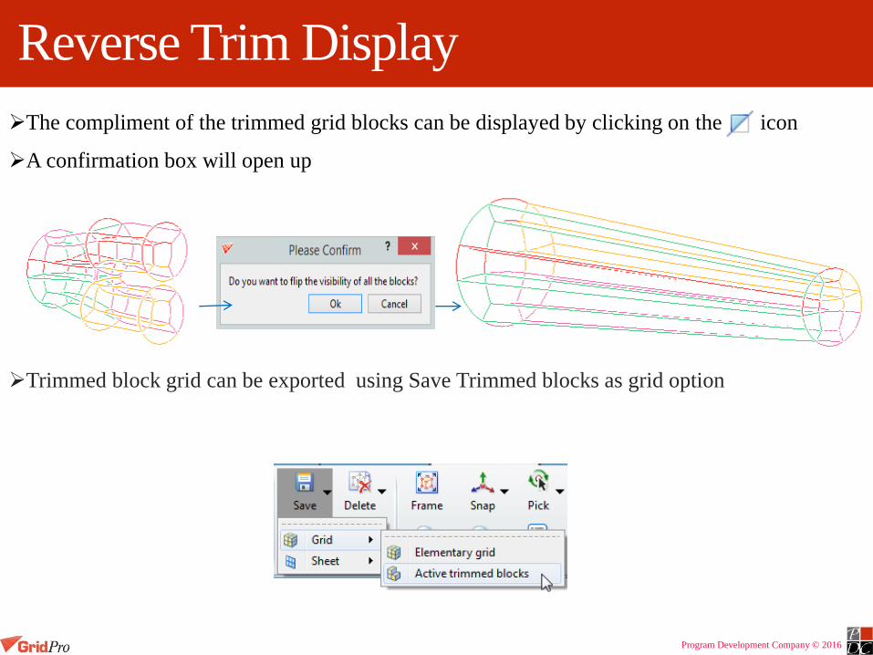
Reverse Trim Display
The compliment of the trimmed grid blocks can be displayed by clicking on the icon
A confirmation box will open up
Trimmed block grid can be exported using Save Trimmed blocks as grid option

Program Development Company © 2016
Redisplaying All Blocks
All of the trimmed grid blocks can be returned to their original display mode by clicking on the icon
A confirmation dialog box will open

Program Development Company © 2016
Trim Grid Sheets
Trim grid sheet work only on Current Sheet
Click on Trim icon
Click on Sheets tab
All the operations work similar to block trim operations
Subtracts the grid sheet
for selected grid block
centres
Program Development Company © 2016
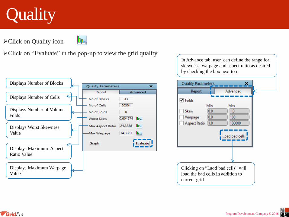
Quality
Click on Quality icon
Click on “Evaluate” in the pop-up to view the grid quality
Clicking on “Laod bad cells” will
load the bad cells in addition to
current grid
In Advance tab, user can define the range for
skewness, warpage and aspect ratio as desired
by checking the box next to it
Displays Number of Blocks
Displays Number of Cells
Displays Number of Volume
Folds
Displays Worst Skewness
Value
Displays Maximum Aspect
Ratio Value
Displays Maximum Warpage
Value

Program Development Company © 2016
Extract
Extract option lets you extract topology from grid
Surfaces and wireframe can be extracted from grid
If Extract icon is
selected, a confirmation
dialog box pops-up
Topology extracted
from the given grid

Program Development Company © 2016
Mirror
Mirror creates a reflective copy of grid
Reflective copy merged with original gird will be loaded into UI previous grid
A reflective grid can be created along X, Y, Z direction or along periodic direction as selected from drop down menu

Program Development Company © 2016
Density
Number of grid points can be changed even after grid is generated
Density can be changed in four ways
If density is modified, new grid is loaded replacing the previous grid
Grid density for this edge has been changed to 50 from 21
Parallel edges of a Grid can be changed by defining new value
under Edge tab

Program Development Company © 2016
Density
Using Matching option, entire grid density can be changed
All edges having the same value as mentioned in existing density will be changed to new density
All edges grid density can be increased or decreased by given ratio
Multiple grids based upon ratio, number of grids and increment method given can be created under this option
Provide the ratio, number of grids to be created and select one of the increment method i.e. arithmetic or geometric to create number of grid files from the given grid file with varying number of grid points

Program Development Company © 2016
Surface
The functions of Surface tab are
• Creating inbuilt surfaces
• Inspecting surfaces
• Surface repair
• Segmenting surfaces
Surface modification tools
Surface repair and inspection tools
Built-in surface creation tools
These tools
have been
discussed
previously

Program Development Company © 2016
Thin
Reduces the number of triangulation in the surface based on the ratio and/or angle.
Surface has
been thinned
based upon
ratio and angle
Define ratio
Define maximum
deviation angle
Define output file
name

Program Development Company © 2016
Refine
• Increases the number of triangulation in the surface based on the given refinement level.
• Feature corner group – Group of corners whose location, if lies on the surface will not be smoothed
Define feature corner group (Not
necessary)
Define refinement level
Define output file name
Surface has been
refined based upon
refinement level
Check the box if smoothing on
surface required

Program Development Company © 2016
Inspection Tools
• Border – Check for surface border and holes
• Angle – Check for any unusual links or bad elements in the surfaces
Border button works as toggle button – Depressing it will show the current surface border,
un-depressing it will hide the surface borders.
Surface shown
with border Only surface
border is shown

Program Development Company © 2016
Angle
Shows the bad elements of the surface based on the given angle.
Highlights the elements in pink color
Enter an angle to view the bad
elements above the given value
and click apply.
Clicking on clear will remove the
highlighted lines.
Clicking on Next will show the bad
elements which has the maximum
angle.
Keep clicking on next will keep
highlighting the bad elements of with
the next (lower) level of significance

Program Development Company © 2016
Splitting Surface
Split the current surface based on wherever the
given threshold angle exceeds.
By default, it takes 45 degree, if you ant change
the angle, then enter the value in the input field,
by enabling the Threshold angle check button.
Split can also be done manually by
creating a closed path about which
the surface will be split.
Split can also be done by trimming
away a part of the surface
It is used for splitting current surface
Three ways splitting can be done
• By defining angle
• By creating path
• By selecting surface elements

Program Development Company © 2016
Split Surface using Path
Step 1: Make the desired surface, current
Step 2: Change the surface display to HLR
Step 3: Click on ‘Split’ button and switch to ‘curve’ tab and select button.
Step 4: Click on the triangle vertices and a path will be drawn as shown.
Path1 2
3
Allow you to pick individual triangular edges

Program Development Company © 2016
Contd…
Step 5: Complete the path selection and make it closed.
Step 6: Click on the ‘Segment’ button and the surface will be segmented

Program Development Company © 2016
Contd…
Step 7: Once the surface is split, it has
to be saved. Click on Save button and
enter a name in the file dialog box to
save the current surface file
Step 8: To save the other surface(yellow color), click
on the Next button to make the other surface,
current and save the file.
Step 9: Clicking on ‘save path’, will allow you to save the path selected as a linear file.

Program Development Company © 2016
Contd…
1
2
Undo the last selected path
To remove any selected path.
Either pick the nodes as shown or drag
a box around the path to be removed nDelete all the paths

Program Development Company © 2016
Fill Surface Holes
Fill a hole with triangles using the existing nodes.
New nodes will not be created on the hole boundary but it will be created inside the hole.
Step 1: Locate the surface hole
Step 2: Change the surface display to shade with HLR
Step 3: Create path around the hole using the path selection tools.
Step 4: Click on Fill button to fill the region inside the selected path.
Step 5: Click on ‘Save modifications’ to save the modified surface.

Program Development Company © 2016
Move Surface Nodes
Surface nodes can be moved parallel or perpendicular to workplane to remove
kinks or repair bad elements
Move the surface nodes parallel to
workplane
Move the surface nodes normal to
workplane
Clears all surface node movementSaves the surface with the same name
and moves the original surface to
<original_filename.0.tria>
Undo/Redo previous surface node
movements
Program Development Company © 2016
Surface Parameters
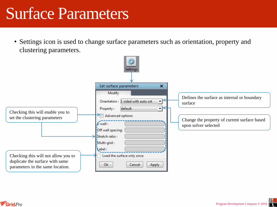
• Settings icon is used to change surface parameters such as orientation, property and
clustering parameters.
Change the property of current surface based
upon solver selected
Checking this will enable you to
set the clustering parameters
Checking this will not allow you to
duplicate the surface with same
parameters in the same location.
Defines the surface as internal or boundary
surface

Program Development Company © 2016
Surface Modification Tools
• Shows the current surface’s dialog box with its dimensions.
• Helps to modify the current surface dimensions.
• Works only for the built-in surfaces.
Scale the current surface or active
surface group based on the center and
ratio
• Shows the current surface’s dialog box with its dimensions.
• Helps to duplicate the current surface either with same/different
dimensions.
• Works only for the built-in surfaces.
Scale
Copy
Reload

Program Development Company © 2016
Contd…
Surface transformation tool similar to
general button in the topology tab.
Works only for the current surface.
The transformation will applied in the order
as in the dialog box.
Translation
Scaling
Rotation
2nd Translation
Mirroring
Transform

Program Development Company © 2016
Surface Creation
GridPro can create surfaces from the wireframe in three formats.
Linear
Quad
Tube
Creates a quad surface
Creates a linear surfaceCreates a tube surface
Program Development Company © 2016
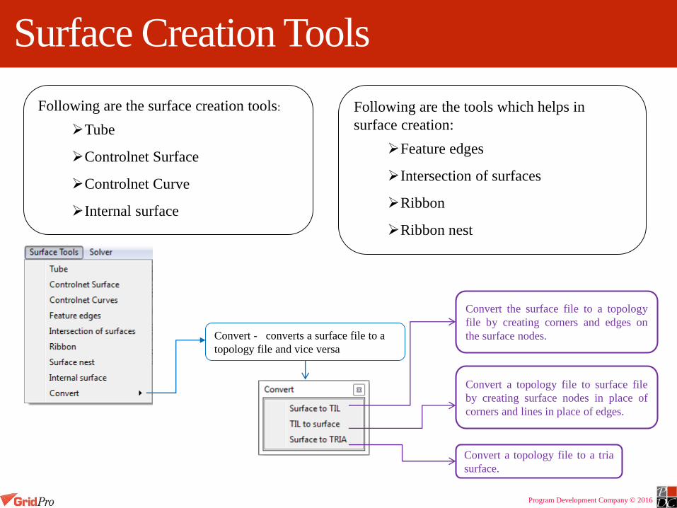
Surface Creation Tools
Following are the surface creation tools:
Tube
Controlnet Surface
Controlnet Curve
Internal surface
Convert - converts a surface file to a
topology file and vice versa
Following are the tools which helps in
surface creation:
Feature edges
Intersection of surfaces
Ribbon
Ribbon nest
Convert the surface file to a topology
file by creating corners and edges on
the surface nodes.
Convert a topology file to surface file
by creating surface nodes in place of
corners and lines in place of edges.
Convert a topology file to a tria
surface.

Program Development Company © 2016
Feature Edges
Creates corners on the surface based on the feature angle.
It calculates the feature angle of each node on the surface and
creates corners at the nodes wherever it exceeds the given
feature angle.
Checking ‘Include boundary edges’ will create corners on the
surface boundaries also.

Program Development Company © 2016
Intersection of Surfaces
Creates corners on the intersection of the given surfaces.
A surface group is given as input which contains the intersecting surfaces.
Corners generated at the
intersection of two
surfaces

Program Development Company © 2016
Ribbon
Creates a layer of corners either normally inwards or normally outwards to the given set of
corners with the given width.
A corner group with corners assigned to a surface must exist.
The normal will be calculated based on the surface normal to which the corners are assigned to.
Corner group for which the ribbon has to be generated.
Corner group for which the normal will be retained.
Corner group for which the normal will be inverted.
Number of times the smoothing algorithm has to be
run.
Width of the ribbon. Distance between the path group
corners and the ribbon generated corners.
Program Development Company © 2016
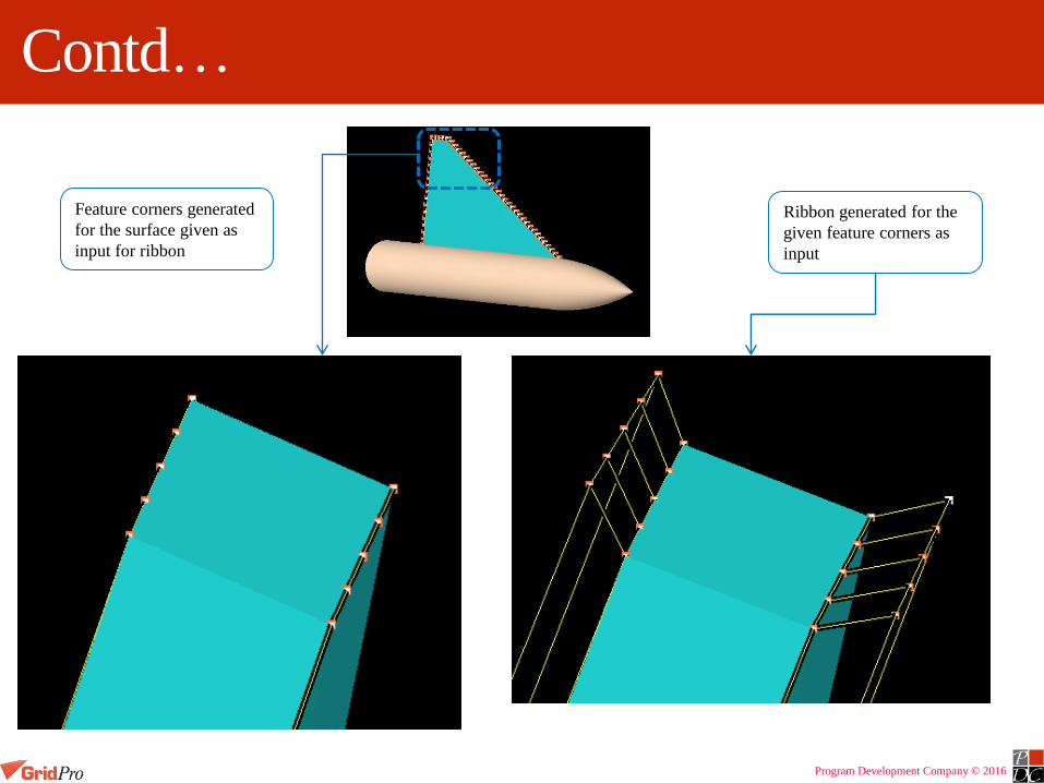
Contd…
Feature corners generated
for the surface given as
input for ribbon
Ribbon generated for the
given feature corners as
input

Program Development Company © 2016
Ribbon Nest
Creates given number of layer of corners in orthogonal direction.
The number of corners reduces with each layer in a pattern as shown below.
A layer of corners which was created by feature edges must exist.
A ribbon layer must exist.
Corner group with both the layer of
corners created by feature edge and
ribbon
Corner group from which the nesting has
to be started
Corner group in which
nesting will not be applied
Number of times the
nesting has to be applied.
Distance between each nesting layer.
Ratio is calculated based on the ribbon
width(used in the ribbon)
Corner group in which the
last layer of nesting will be
grouped.
Corner group for which the distance
between each layer will be fixed.
Number of times the smoothing algorithm
has to be applied.Checking this, will apply
wrap on the last layer of
nesting
Program Development Company © 2016
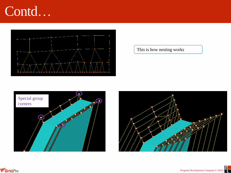
Contd…
This is how nesting works
Special group
corners

Program Development Company © 2016
Internal Surface
Creates a closed surface which is orthogonal to the surface intersection using the corners
created at the intersection.
Corners created with ‘Intersection of surfaces’ must exist.Corner group whose corners created at
the intersection of surfaces.
Surface group whose surface normal has
to be inverted
Type of algorithm has to be used.
Method of creating internal surface
Number of times the smoothing
algorithm has to be applied
Number of corners has to be created on
the other side of the surface to ensure
that the surface is passed through the
intersection.
Controls the height till which the
orthogonality has to be maintained.
Decides the height of the surface

Program Development Company © 2016
Tube Surface
• Creates a tube surface using the axis and radius information.
• It’s also a input format in GridPro
• Four different input ways to create a tube:
Axis can be defined either
using a corner group which
defines an axis or using x y
x values
• Radius can be defined
either using a corner
group or using x y x
values.
• The distance between
the corner group and
the axis is calculated as
radius implicitly.Applies smoothing
algorithm
Number of times the
refinement has to be
done
Closes the tube on both
sides
Axis Radius
Corner group Corner group
Corner group Value
Orientation Corner group
Orientation Value

Program Development Company © 2016
Controlnet Surface
Creates a quad surface from the given wireframe.
The wireframe should contain valid blocks (i.e. each block should have only 4 edges in2D,
6 edges in 3D).
Corner group from which the surface has to be created.
Corner group where the surface will exactly pass through.
Smoothing will not be applied here.
Corner group where smoothing has to be applied
Number of times the refinement has to be applied
Decides the flatness of the surface
Number of times the smoothing algorithm has to be applied
Kind of smoothing to be applied
Method to be used to create the surface

Program Development Company © 2016
Controlnet Curves
Creates a linear surface from the given wireframe.
Works only for 2D.
Corner group from which the curve has
to be created
Number of times the refinement has to
be applied.
Method to be sued to create the curve

Program Development Company © 2016
Properties
Properties can be assigned before gridding or after grid is generated
Before assigning properties select the Solver from the top panel for which grid would be exported
Here Fluent solver is selected
Before gridding, properties are assigned to surfaces and after gridding properties are assigned to grid sheets and grid blocks

Program Development Company © 2016
Properties Assigned to Surfaces
In Surface tab, click on settings icon
In the pop-up select the appropriate property for current surface from the drop down menu
Properties assigned to surfaces would be reflected in the grid sheets

Program Development Company © 2016
Property Setter Toolbar
3d property for blocks
2d property for faces
By default each grid will have two 2d properties i.e. Interior and Wall assigned
Each grid would have fluid as 3d property
Faces assigned as wall property is shown
Faces assigned as interior property is shown

Program Development Company © 2016
Property Setter Toolbar
List of 2d properties List of 3d properties
Shows all Property sheets Flips the visibility of property sheets
Shows only current Property
sheet

Program Development Company © 2016
Selecting 2D Property FacesSelect the property from the list and enter the label
Click ‘Apply’ to create the selected property
Click on icon and drag a box around the faces
Drag a box around the hollow squares
representing surface sheet which will assigned
the selected property
A new property sheet created is
shown in sea blue colour
A new property i.e. pressure-outlet
is added to 2d properties lies
Pressure outlet is
selected as new
property

Program Development Company © 2016
ExportingSelect the solver format from Export Grid option under File menu
Specify the name with appropriate extension
Program Development Company © 2016
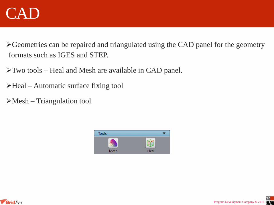
CAD
Geometries can be repaired and triangulated using the CAD panel for the geometry
formats such as IGES and STEP.
Two tools – Heal and Mesh are available in CAD panel.
Heal – Automatic surface fixing tool
Mesh – Triangulation tool
Program Development Company © 2016
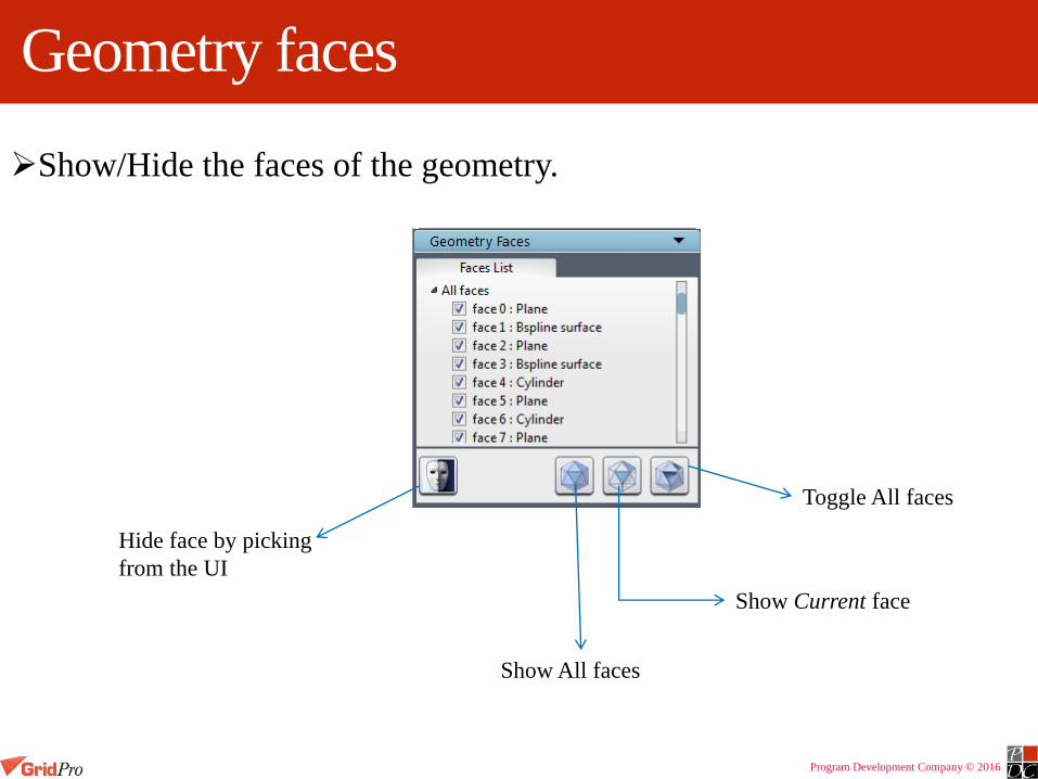
Geometry faces
Show/Hide the faces of the geometry.
Show All faces
Show Current face
Toggle All faces
Hide face by picking
from the UI

Program Development Company © 2016
Heal
Repairs the geometry to fix small edges, fix spot strip faces and sew faces using a tolerance value.
Before Healing the geometry
After Healing the geometry

Program Development Company © 2016
Mesh
Creates surface mesh for the imported geometry.
After creating the surface mesh for
the geometry

Program Development Company © 2016
Local Mesh
Create surface mesh locally for certain faces.
Right click on the face whose surface mesh has to be changed.
Select ‘Set face mesh size’
Enter the new mesh size and click ‘ok’.
With default mesh size
With new face mesh
size