
Grid Disturbance Analysis and Comments - IIT Bombaycs620/Blackout_FINAL.pdf · why interconnect to...
63
Power Grids Normal Operation and Failures A.M.Kulkarni IIT Bombay
Transcript of Grid Disturbance Analysis and Comments - IIT Bombaycs620/Blackout_FINAL.pdf · why interconnect to...

Power Grids Normal Operation and Failures
A.M.Kulkarni
IIT Bombay

My talk…
Power System
- Structure, Operation and Control
An example of a Power Grid: India
An example of a Grid Failure

"Except for a few islands and some small isolated systems, the
entire electric grid is really one big circuit.
The humble wall outlet is actually a gateway to one of the largest
and most complex objects ever built. The grid encompasses
billions of individual components, tens of millions of miles of wire
and thousands of individual generators "
Thomas Overbye,
Re-engineering the Electric Grid, American Scientist, 2000, Vol. 88, Iss. 3.

Bulk Power Systems

Common Doubts for a non-specialist
Why interconnect to form large grids ?
Why AC and not DC ? Role of DC in modern power grids
Why 50 Hz / 60 Hz ?
Why Three phase ?

Synchronous Links
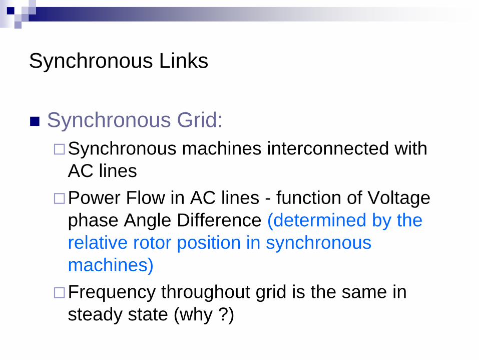
Synchronous Grid:
Synchronous machines interconnected with
AC lines
DC DC
Transmission
Lines
Induction Generators ?
Synchronous Links
Synchronous Grid:
Synchronous machines interconnected with
AC lines
Power Flow in AC lines - function of Voltage
phase Angle Difference (determined by the
relative rotor position in synchronous
machines)
Frequency throughout grid is the same in
steady state (why ?)

Synchronous Links
Synchronous Grid:
Synchronous machines interconnected with
AC lines
DC DC
Transmission
Lines
Induction Generators ?
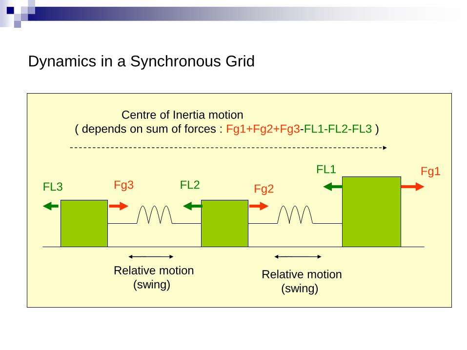
Dynamics in a Synchronous Grid
Relative motion
(swing)
Centre of Inertia motion
( depends on sum of forces : Fg1+Fg2+Fg3-FL1-FL2-FL3 )
Fg1
Fg2 Fg3 FL3 FL2
FL1
Relative motion
(swing)
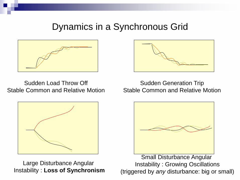
Dynamics in a Synchronous Grid
Sudden Load Throw Off
Stable Common and Relative Motion
Sudden Generation Trip
Stable Common and Relative Motion
Large Disturbance Angular
Instability : Loss of Synchronism
Small Disturbance Angular
Instability : Growing Oscillations
(triggered by any disturbance: big or small)

Effect of Lack of Synchronism in AC ties
Not Acceptable ! Distance Relays trip Uncontrolled System Separation
Asynchronous Links
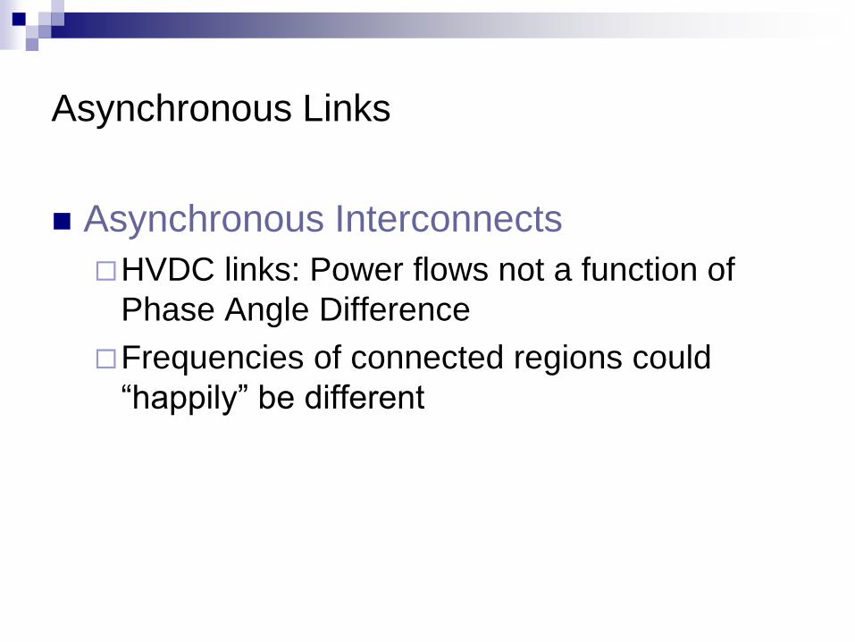
Asynchronous Interconnects
HVDC links: Power flows not a function of
Phase Angle Difference
Frequencies of connected regions could
“happily” be different
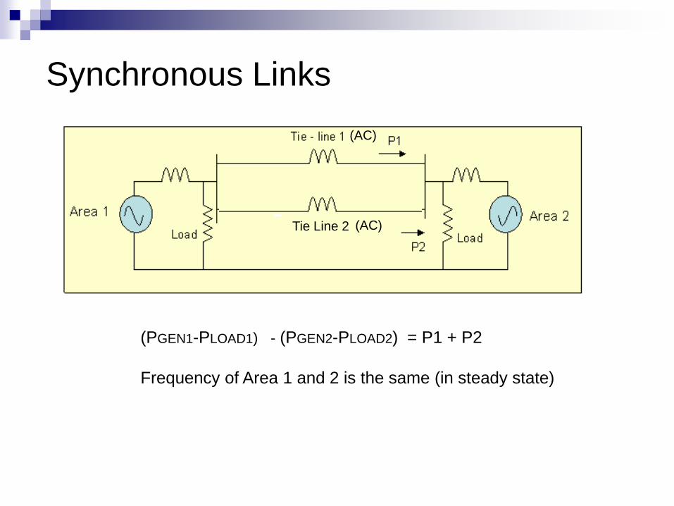
Synchronous Links
Tie Line 2
(AC)
(AC)
(PGEN1-PLOAD1) - (PGEN2-PLOAD2) = P1 + P2
Frequency of Area 1 and 2 is the same (in steady state)

Asynchronous Link
Frequency of Area 1 and 2 need not be the same

Synchronous or Asynchronous ?
(PGEN1-PLOAD1) - (PGEN2-PLOAD2) = P1 + P2
Frequency of Area 1 and 2 is the same (in steady state)
Issues in Interconnected Systems
Ownership
Monitoring & Control Hierarchy
Cooperation and Coordination is
necessary!


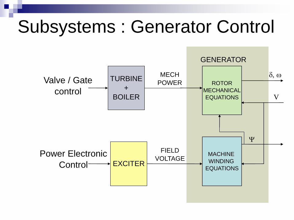
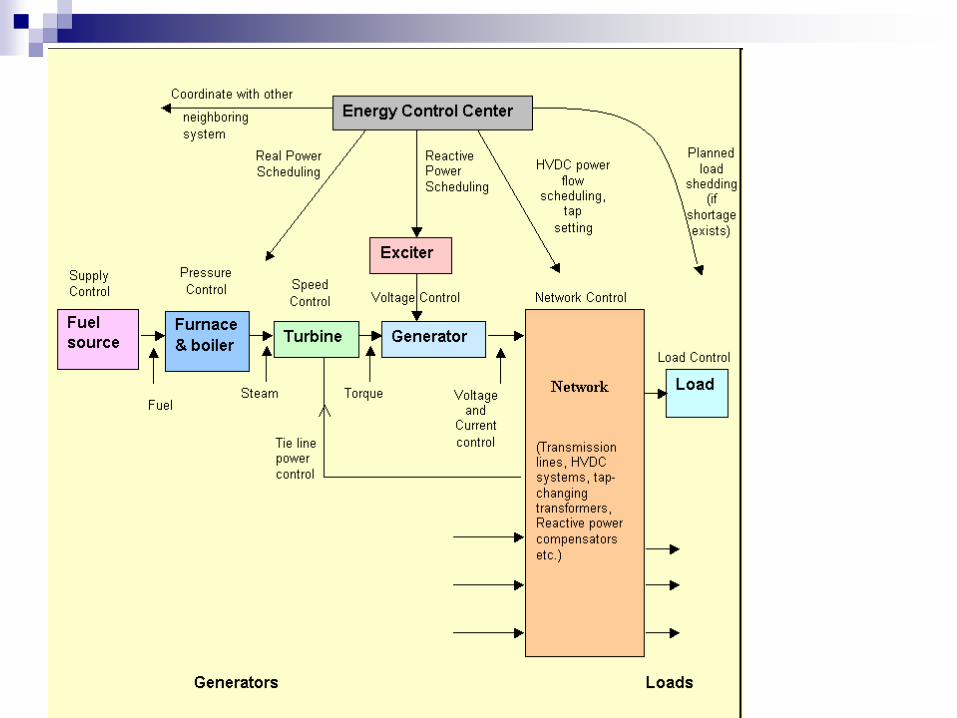
Subsystems : Generator Control
ROTOR
MECHANICAL
EQUATIONS
MACHINE
WINDING
EQUATIONS
GENERATOR
FIELD
VOLTAGE
MECH
POWER
V
EXCITER
TURBINE
+
BOILER
Valve / Gate
control
Power Electronic
Control

Static Excitation: Voltage Control
DC AC
Controlled Rectifier
Main Generator

AVR
ROTOR
(MECHANICAL
EQUATIONS)
MACHINE
WINDING
EQUATIONS
GENERATOR
FIELD
VOLTAGE
MECH
POWER
V
EXCITER
TURBINE
and/or
BOILER
Gate/ Valve (mech)
Control by governor
Power
Electronic
Valve
Control AVR
NETWORK
Terminal Voltage of Generator
Reference
Voltage

Frequency Control
Frequency Depends on Cumulative Load-
Gen Balance in a Synchronous Grid
Load is Weakly Frequency Dependent
Generation-Load Balance has to be
Maintained.
Generation Control or Load Shedding
Subsystems : Generator Control
ROTOR
MECHANICAL
EQUATIONS
MACHINE
WINDING
EQUATIONS
GENERATOR
FIELD
VOLTAGE
MECH
POWER
V
EXCITER
TURBINE
+
BOILER
Valve / Gate
control
Power Electronic
Control

Primary Control
Speed Control (Governor)
Load Sharing by different generators: Droop Control
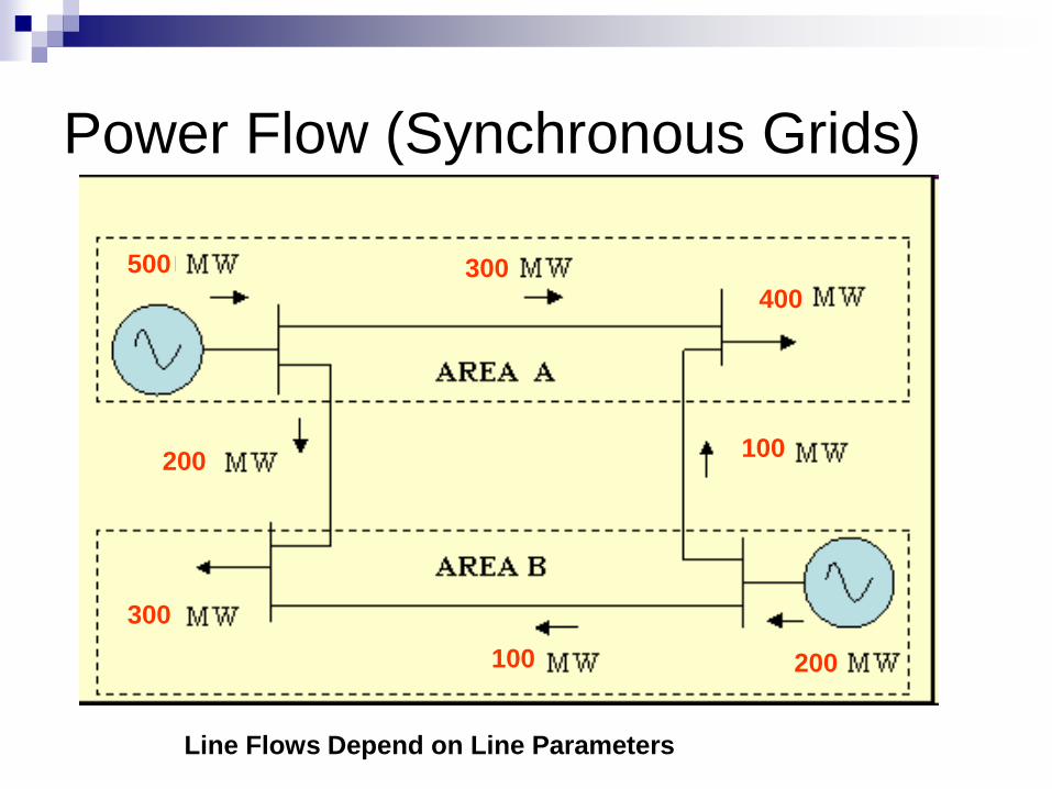
Power Flow (Synchronous Grids)
500
200
400
300
Line Flows Depend on Line Parameters
100
200 100
300

Power Flow (Synchronous Grids)
600
400
200
800
500
300 100
300

Power Flow Control in AC lines
Modulation also possible with these devices

Control Centre

RTU
SUB LDC
SLDC
RLDC
NLDC
31
Nos.
51 Nos.
1649 Nos.
5 Nos.
Plant/Sub Station Level
Group of District Level
State HQ
Level
Region Level
National Level
Unified Load
Despatch &
Communication
Present SCADA/EMS – Multi way information Flow
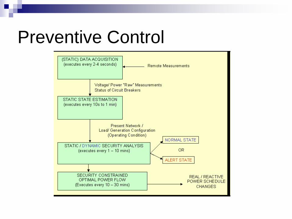
Preventive Control
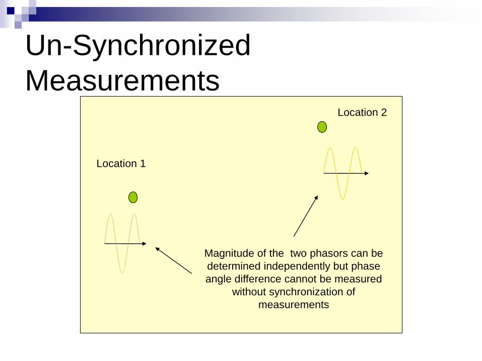
Un-Synchronized
Measurements
Location 1
Location 2
Magnitude of the two phasors can be
determined independently but phase
angle difference cannot be measured
without synchronization of
measurements

Synchronized Measurements
Location 1
Location 2
Phase angular difference between the
two can be determined if the two local
clocks are synchronized.
Synchronizing pulses obtained from
GPS satellites.

WAMS

The Indian Power
Grid

Indian Power System : Among the Largest in the World National Grid (UK)
68GW
MidWest ISO (USA)
159GW
RTE (France)
93GW
PJM (USA)
165GW
Red Electrica (Spain)
93GW
ONS (Brazil)
100GW
SO - UPS (Russia)
146 GW
Tepco (Japan)
64GW
KPX (South Korea)
70GW
Terna (Italy)
57GW
SGCC (China)
900GW
PGIL (India)
163GW Eskom
(South Africa)
43.5GW
Source: VLPGO (~2011)

Some Typical Numbers (~2011) Generating Units :~ 1600
400kV & above Trans. Line :~ 700
Transformers (High Voltage) :~ 2000
Busses (Extra High Voltage) :~ 5000
Control Areas :~ 100
Inter-State Metering Points :~ 3000
Open Access transactions typical daily :~ 100
Captives participating in market :~ 125
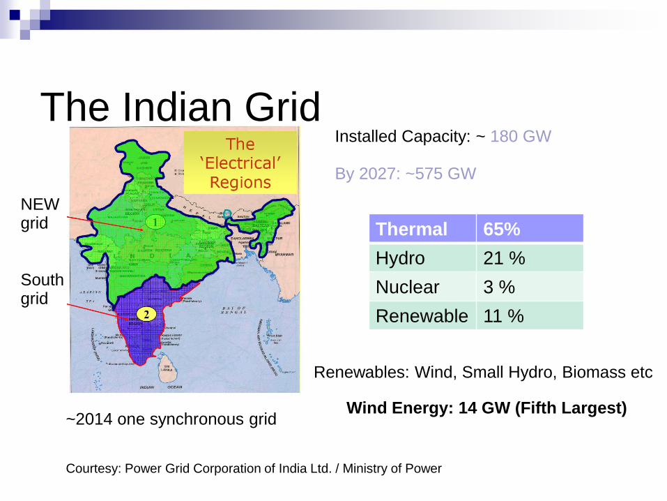
The Indian Grid
NEW grid
South grid
Installed Capacity: ~ 180 GW By 2027: ~575 GW
~2014 one synchronous grid
Courtesy: Power Grid Corporation of India Ltd. / Ministry of Power
Thermal 65%
Hydro 21 %
Nuclear 3 %
Renewable 11 %
Renewables: Wind, Small Hydro, Biomass etc
Wind Energy: 14 GW (Fifth Largest)
NEW Grid
South Grid
South
West
North
East
Northeast
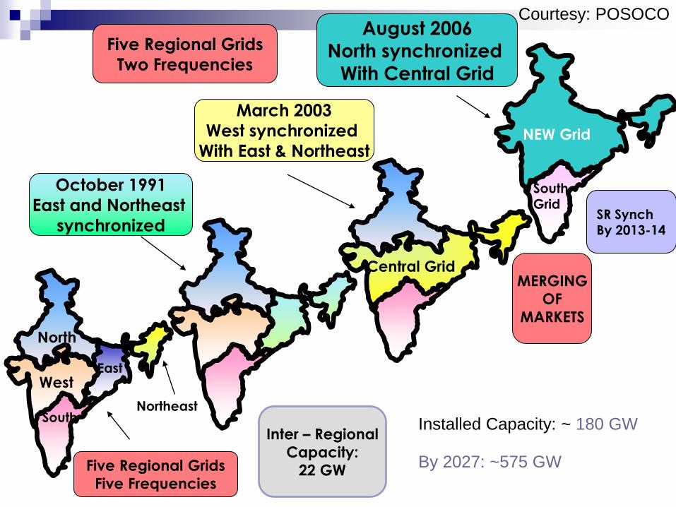
Five Regional Grids
Five Frequencies
October 1991
East and Northeast
synchronized
March 2003
West synchronized
With East & Northeast
August 2006
North synchronized
With Central Grid
Central Grid
Five Regional Grids
Two Frequencies
MERGING
OF
MARKETS
SR Synch By 2013-14
Inter – Regional
Capacity:
22 GW
Courtesy: POSOCO
Installed Capacity: ~ 180 GW By 2027: ~575 GW

The Indian Grid: HVDC
HVDC (Long Distance)
1. Rihand – Dadri
2. Chandrapur – Padge
3. Talcher – Kolar
4. Balia - Bhiwadi
BACK To BACK
1. Vindhyachal
2. Bhadravati
3. Gazuwaka
4. Sasaram
(1500 MW)

The Indian Grid
Courtesy: Power Grid Corporation of India Ltd. / Ministry of Power
Major Load
Centres

ROURKELA
RAIPURHIRMA
TALCHER
JAIPUR
NER
ER
WR
NR
SR
B'SHARIF
ALLAHABAD
SIPAT
GAZUWAKA
JEYPORECHANDRAPUR
SINGRAULI
VINDHYA-
2000M
W
2000MW
2500MW
1000MW
500MW
LUCKNOW
DIHANG
CHICKEN NECK
TEESTA
TIPAIMUKH
BADARPUR
MISA
DAMWE
KATHAL-GURI
LEGEND
765 KV LINES
400 KV LINES
HVDC B/B
HVDC BIPOLE
EXISTING/ X PLAN NATIONAL
ZERDA
HISSAR
BONGAIGAON
DEVELOPMENT OF NATIONAL GRID
KOLHAPUR
NARENDRA
KAIGA
PONDA
IX PLAN
MARIANI
NORTH
KAHALGAON
RANGANADI
SEONI
CHEGAON
BHANDARA
DEHGAM
KARAD
LONIKAND
VAPI
GANDHAR/
TALA
BANGLA
BALLABGARH A'PUR(DELHI RING)
BANGALORE
KOZHIKODE
COCHIN
KAYAMKULAM
TRIVANDRUM
PUGALUR
KAYATHAR
KARAIKUDI
CUDDALORE
SOUTH CHENNAI
KRISHNAPATNAM
CHITTOOR
VIJAYAWADA
SINGARPET
PIPAVAV
LIMBDI
KISHENPUR
DULHASTI
WAGOORA
MOGA
URI
BHUTAN
RAMAGUNDAM
SATLUJRAVI
JULLANDHAR
DESH
VARANASI/UNNAO
M'BAD
PURNEA
KORBA
NAGDA
SILIGURI/BIRPARA
LAK
SH
AD
WE
EP
TEHRI
MEERUT
BHIWADI
BINA
SATNA
MALANPURSHIROHI
KAWAS
AMRAVATI
AKOLA
AGRA
SIRSI
CHAL
JETPURAMRELI
BOISARTARAPUR
PADGHE
DHABOL
KOYNA
BARH
G'PUR
HOSURMYSORE
KUDANKULAM
M'PUR
KARANPURA
MAITHON
JAMSHEDPUR
PARLI
WARDA
BEARILLY
SALEM GRID
XI PLAN
765 KV LINES IN X PLAN. TO BE CHARGED AT 400KV INITIALLY
TO BE CHARGED AT 765 KV UNDER NATIONAL GRID
765 KV RING MAIN SYSTEM
THE POWER
‘HIGHWAY’
CHEAP HYDRO POWER FROM
THE NORTH-EAST AND PIT
HEAD THERMAL POWER
FROM THE EAST ENTERS THE
RING AND EXITS TO POWER
STARVED REGIONS
Cheap Thermal
Courtesy: POSOCO
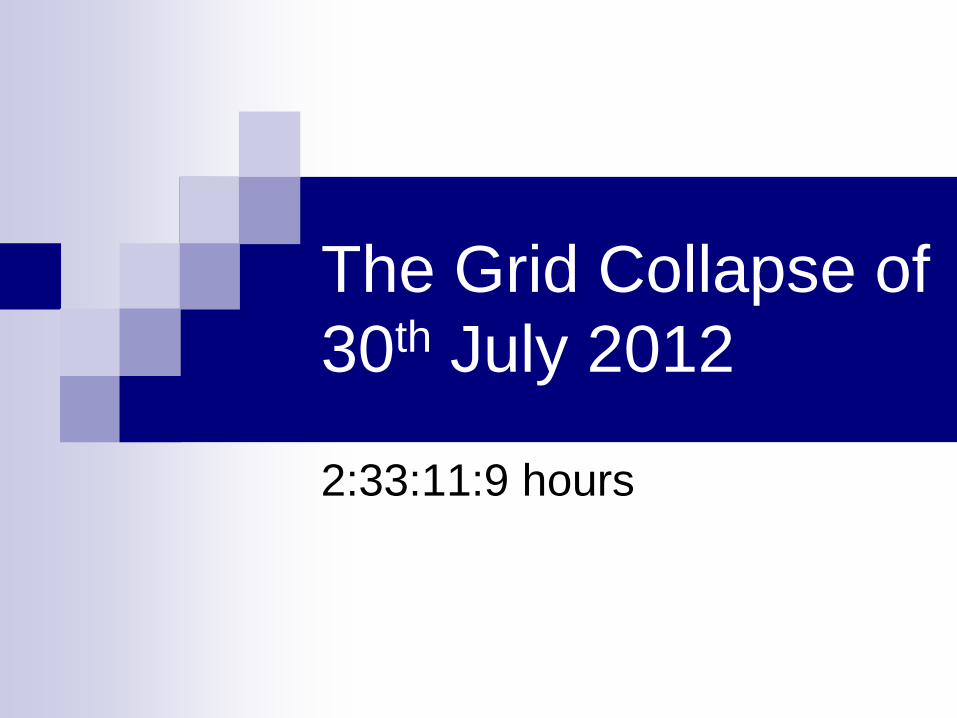
The Grid Collapse of
30th July 2012
2:33:11:9 hours

From Geet Ramayana (G.D.Madgulkar)
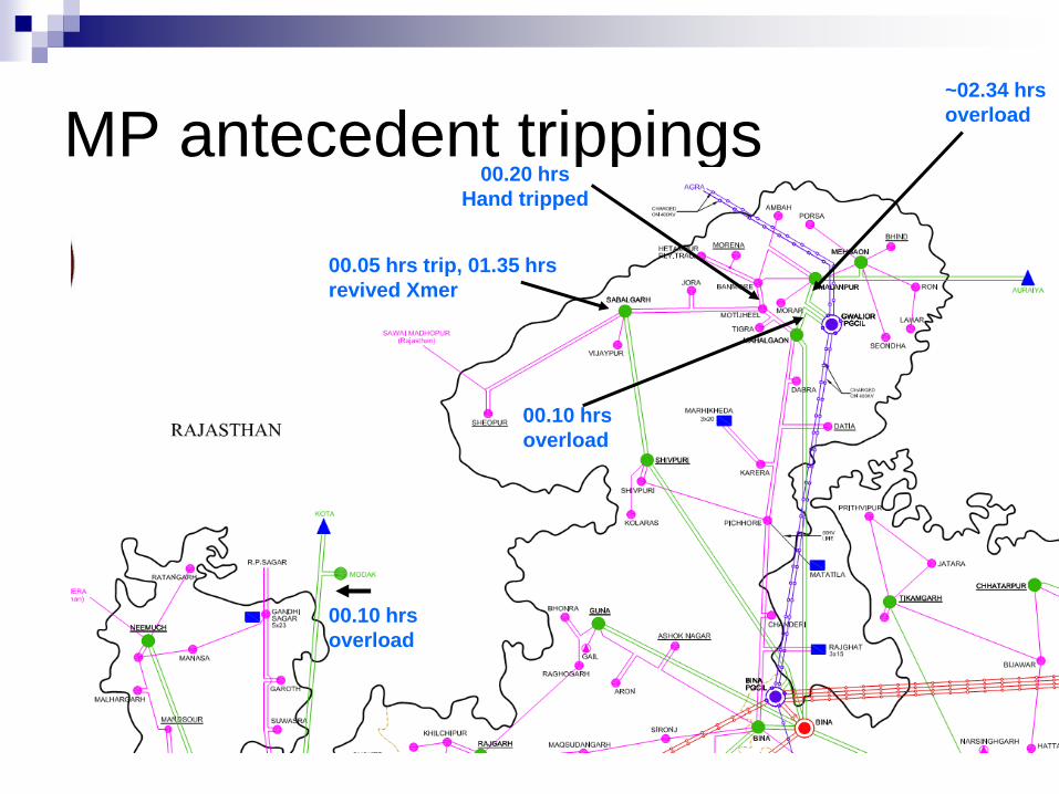
MP antecedent trippings
00.10 hrs
overload
00.05 hrs trip, 01.35 hrs
revived Xmer
00.20 hrs
Hand tripped
00.10 hrs
overload
~02.34 hrs
overload

-278 MW
2654 MW
832 MW
975 MW
835 MW
962 MW
-33 MW
95 MW
1192 MW
3123 MW
2710 MW
2650 MW
Scheduled vs Actual Flows
02:30 hours
Frequency : 49.68 Hz
(asynchronous tie)
(asynchronous tie)
Bhutan
Demand met > 70 GW
in NEW grid
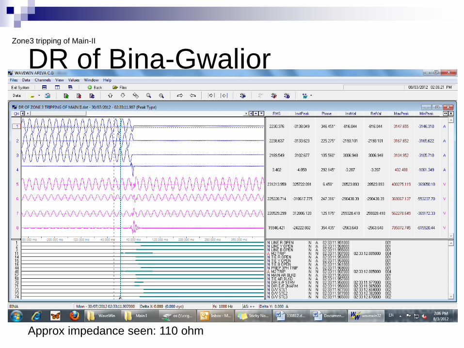
DR of Bina-Gwalior Zone3 tripping of Main-II
Approx impedance seen: 110 ohm

“Distance Protection”
I
V1
V1 is normally much greater than the impedance of the line ZL.
Normal
V2
I
ZL

Distance Protection
I
V1
Voltage at fault point is ~zero
Fault
V1 will be equal to Z
Relay setting to detects fault on this line V1 < ZL ; immediate trip
Relay setting (back-up) for faults on neighbouring line V1 < ZL + ZL1
Z
I
I
I (Slow trip setting)

PMU data 30-7-2007, 2:33 hours
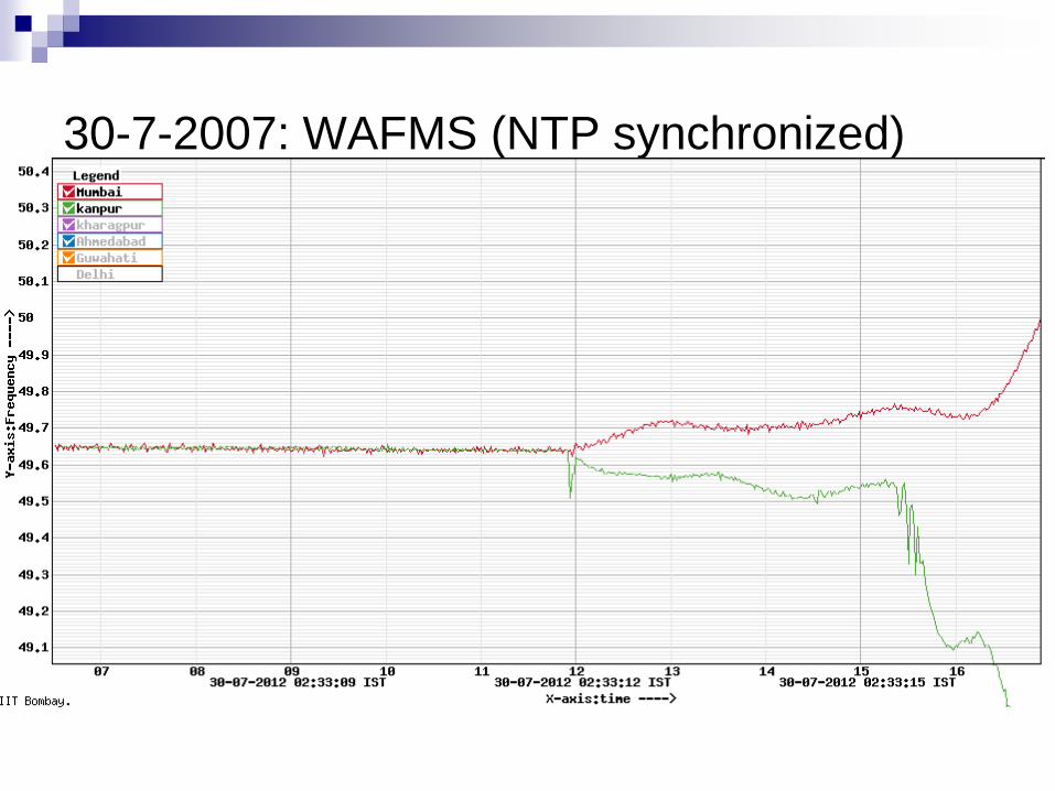
30-7-2007: WAFMS (NTP synchronized)
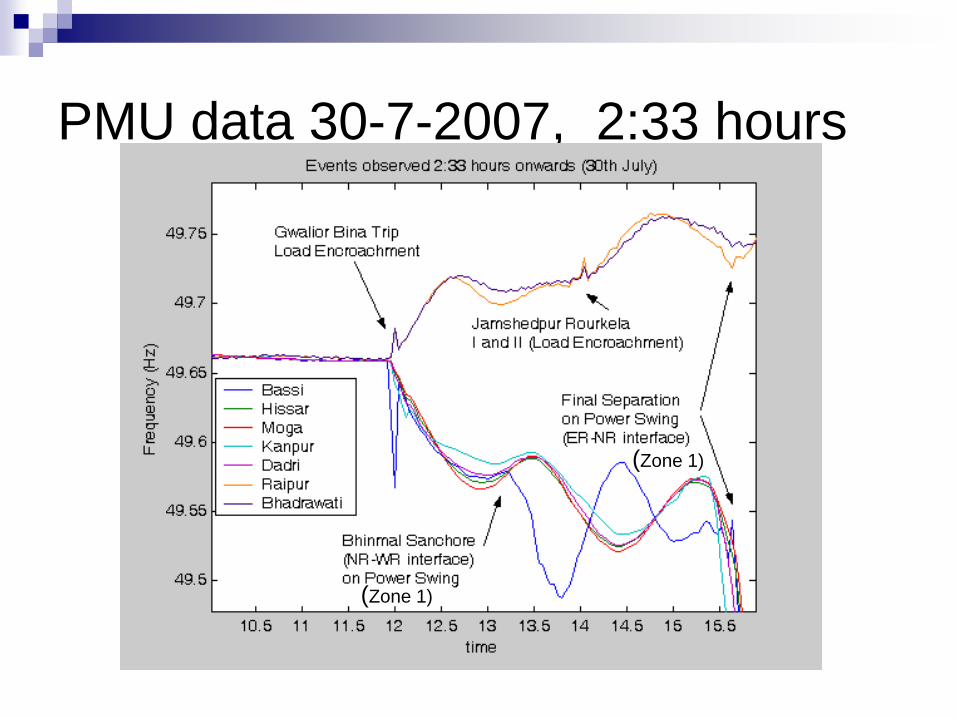
PMU data 30-7-2007, 2:33 hours
(Zone 1)
(Zone 1)

First Conclusion
The critical event leading to large angular
separation was Gwalior-Bina 400 kV trip
From DR, PMU, WAFMS : Tripping time is
established to be 2:33:11:9
Trip was NOT on fault.
Zone3 tripping (back-up protection)
“Load encroachment”
x

Zone-1 trippings at ~2:33:15, due to large angular
separation ---- NR becomes an island
Balia-Biharsharif
Balia-Patna
Grkpr-Muzzpr.
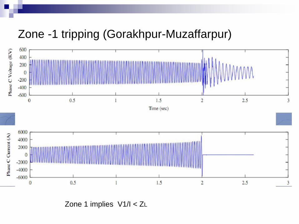
Zone -1 tripping (Gorakhpur-Muzaffarpur)
Zone 1 implies V1/I < ZL

Cut-Set
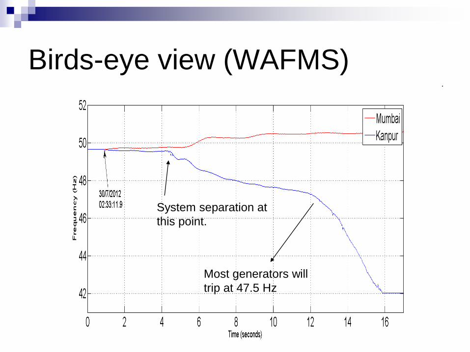
Birds-eye view (WAFMS)
System separation at
this point.
Most generators will
trip at 47.5 Hz

Issues
Extreme Insecure Operation due to multiple line
outages (forced/planned).
Tripping on overload (220 kV) -
Tripping on load-encroachment (Zone 3) – Audit
of settings. Technological solution – use of
PMUs
Reactive Power Absorption: Lines opened on
HV (eg Barh Balia) – reduced security

Issues
NR : U/f relaying – very little
WR-ER-NER : Inadequate governor
response
HVDC/TCSC power boost (angular
stability controllers) ?

Restoration
Hydro-units require very little startup power

Restoration

Concluding Thoughts about the Blackout
Back to Basics
Technology:
Wide Area Measurement Systems
Power Electronics based interconnects
The excitement of observing system-wide
dynamic phenomena !


![Vindhya Telelinks Ltd 2007[1]](https://static.fdocuments.us/doc/165x107/577ce7661a28abf103950c19/vindhya-telelinks-ltd-20071.jpg)
