Greening the Chrome Plating Industry - Western Michigan
32
“Greening” the Chrome Plating Industry Matthew Johnson Image Source: Healthcare Furniture Chicago Site: http://www.healthcarefurniturechicago.com/go_green.php Retrieved (2/24/10).
Transcript of Greening the Chrome Plating Industry - Western Michigan

“Greening” the Chrome Plating Industry
Matthew JohnsonImage Source: Healthcare Furniture Chicago
Site: http://www.healthcarefurniturechicago.com/go_green.php Retrieved (2/24/10).

Outline
• The Process
– Hexavalent Chrome
• Environmental and Health Impact
– OSHA, FDA, Clean Water Act
• Current State
– Environmental Measures
– New Processes
• Future
• Implementation

The Chrome Plating Process
• Electroplating
– Also known as electrodeposition.
• Five Key Areas of Interest for Environmental Impactfor Environmental Impact
– Equipment
– Preparation Process
– Process Control
– The Solution (Electrolyte)
– Anodes/Cathodes
Image Source: Steves Plating Corporation, “Chrome Plating” (2010).
Site: www.stevesplating.com/chrome_plating.htm (Retrieved 2/24/20).

The Basics
• A part is submersed into a aqueous bath.
• An electric current is supplied to the bath.
– Positive through anode
– Negative through cathode
• As power is supplied through the anode to the bath, the chromic acid
Cr Cr(+6)
anode to the bath, the chromic acid is oxidized.
– The process causes a loss of 6 electrons forming Cr(+6).
• At the same time the negatively charged catalyst initiates the flow of electrons causing the Cr(+6) to move towards the cathode.
• At the cathode, the Cr(+6) goes through reduction picking up electrons till a zero valence is achieved to plate only Cr.
Basic diagram of the bath solution
and components.
(-) Catalyst initiates reduction = Cr(6)
picking up electrons at cathode
(transforming to Cr(0)
Image Source: Swicofil AG Textile Services
Site: http://www.swicofil.com/textile_metallization.html
Retrieved (2/26/10).

Plating Equipment
• Hold Tank or Vat– Contains the electrolyte solution.
– Made from a non-soluble material. Typically a PVC liner.
• Vat Heating Equipment– Electric submersible heater.
• Rectifier – Provides a constant DC current to the bath.
• Anodes• Anodes– The contact point with the solution provide the positive current to the bath.
• Cathodes and Fixtures– Often combined together to hold the part and maintain the negative connection back to the
rectifier.• Made from non-soluble materials with contact to surface of plating part. Must have contact between
the part and the rectifier. Plastic coated racks are common with a lead connection to the power source.
• Pre-Cleaning– Plating lines will consist of pre-cleaning solutions (detergents, acid baths) as well as chemical
etching baths to provide better adhesion of chromium.

Pre-Plating Process
• Soap-Detergent– Used for a part cleaning or scrubbing to remove dirt contaminants.
• Acid cleaning bath– Commonly use a sulfuric acid bath to remove contaminants.
• Alkaline dip– Basic solution bath for neutralizing acid.– Basic solution bath for neutralizing acid.
• De-ionized water– Used to remove acid and sediment after pre-plating processes.
– Often used after pre-plating (nickel) or etching processes.
• Nickel plating (common for added brightness and shine)– Sometimes applied as corrosion resistant layer that adds visual appeal.
• Etching– Chemically etching a part provides increased adhesion of plating layer.

Process Control
• DC Rectifier– Maintains constant current
with less that 5% current break recommended
• PH, thermal control and specific gravity are all critical to the control of a critical to the control of a hexavalent chromium bath.– Use of PLC interface control
common in high end plating operations.
• Automated process control improves plate thickness consistency and electrolyte solution longevity.
Image Source: TradeIndia.com (2010).
Site: http://www.tradeindia.com/fp102512/Electroplating-Rectifier.html
(Retrieved 2/24/2010)

Electrolyte Solution
• Component (1); chromium trioxide provides the chromium or metal component of the solution usually in the form of an additive salt.
• Component (2); water is
(1) − CrO3
-Chromium Trioxide
(2) − H2O -Water
• Component (2); water is added to the bath.
• The combination of the two components forms chromic acid.
• Typical concentrations range from 20-60 oz/gal of solution.
2 -Water
(3) − CrO3
+ H2O ⇒ H
2CrO
4

Electrolyte Solution (cont’d)
• Component (4) is the addition of a necessary Sulfate ion that acts as a catalyst to initiate the flow of current within the bath.– Usually introduced in the
form of sulfuric acid.
(4) − SO4
−2 - Sulfate ion
H2CrO
4+ SO
4
−2= Traditional
form of sulfuric acid.
• Typical concentration of catalyst is a 100:1 ratio with respect of weight to the chromic acid.
• Ratio is adjusted to change the plating speed and throwing power.
H2CrO
4+ SO
4= Traditional
Solution

Electrolyte Solution (cont’d)
SiF6
2−
• Multi-catalyst baths are often used in hexavalent baths.– Commonly have the addition of
fluoride.
• Fluoride provides better substrate activation when pre-nickel platings are present. - Fluoride ion
•Application of proprietary baths with
multi-catalysts has grown do to
increased plating efficiency and
better adhesion.
SiF6nickel platings are present.
– Nickel plating common for its shiny, bright appearance. Applied prior to addition of a chromium layer.
• Environmental drawbacks with use of fluoride that will be discussed later.
- Fluoride ion
Image Source: “Chemsity, Structures & 3D Molecules @ 3Dchem.com
Site: www.3dchem.com/inorganics/SiF6_2-.jpg (Retrieved 2/24/2010).
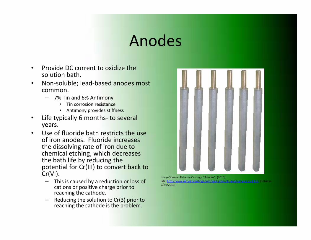
Anodes
• Provide DC current to oxidize the solution bath.
• Non-soluble; lead-based anodes most common.
– 7% Tin and 6% Antimony• Tin corrosion resistance
• Antimony provides stiffness
• Life typically 6 months- to several years.
• Life typically 6 months- to several years.
• Use of fluoride bath restricts the use of iron anodes. Fluoride increases the dissolving rate of iron due to chemical etching, which decreases the bath life by reducing the potential for Cr(III) to convert back to Cr(VI).
– This is caused by a reduction or loss of cations or positive charge prior to reaching the cathode.
– Reducing the solution to Cr(3) prior to reaching the cathode is the problem.
Image Source: Alchemy Castings, “Anodes”, (2010).
Site: http://www.alchemycastings.com/lead-products/anodes/anodes-1.htm (Retrieve
2/24/2010)

Anodes and Cathodes
• The first reaction present when current is applied to the electrolyte is the conversion of hexavalent chromium into trivalent chromium. This is seen in reaction (1) this reaction occurs in proximity to the anode at low current.at low current.
• The Cr(VI) is reduced to chromium metal (Cr) and applied to the workpiece at the cathode. This is seen in reaction (3).
• When this reaction (3) occurs, hydrogen gas is given off at the cathode. This is seen in reaction (2).
(1) − Cr+6
→ Cr3
(2) − 2H+
→ H2
(3) − Cr6+
→ Cr0
Image Source: Tirgar et al “Design and Performance of Chromium Mist Generator”
Site: http://www.scielo.br/scielo.php?script=sci_arttext&pid=S0103-50532006000200018
Retrieved (2/24/10).

Anodes and Cathodes
• When current is applied to the cell; the reaction at the anode is as follows. The lead anode forms lead dioxide as oxidation occurs on the surface (brown) shown in reaction (1).
• When reaction (1) occurs, the water in the electrolyte • When reaction (1) occurs, the water in the electrolyte gives off primarily oxygen and some hydrogen cations.
• Finally, Cr(III) turns back to Cr(VI) in reaction (3) at the anode.
(1) − Pb0
→ Pb03 (2) − 2H2O → O2 + 4H
+(3) − Cr
3→ Cr
6+

Summary of Reactions
(1) − Pb0 → Pb03
(1) − Cr+6
→ Cr3
(2) − 2H+
→ H2
Simultaneous
(1) − Pb0 → Pb03
(2) − 2H2O → O2 + 4H+
(3) − Cr3
→ Cr6+
(3) − Cr6+
→ Cr0

Environmental and Health
• OSHA, 2/28/06
– Can not release dust, fumes or mists from the operation.
– 5.0
• Rinse water Disposal
– FDA and local government guidelines for permissible concentrations that are allowed into municipal
µg / m3
– 5.0
• Maximum allowable 8 hour concentration exposure. (PEL)
• Must take air samples during working hours.
– Results have to be presented to employees within 15 days.
allowed into municipal sewers.
– Rinse water may need to be deposed at proper facilities if chromium content is not removed below allowable limits.
µg / m

Pre-Plating Health and Environmental Concerns
• De-ionized water baths need to be properly managed for contaminants.– Treated water needs to be
within limits.
• Use of filtration methods are needed for proper disposal of
• Nickel plating – Respiratory Concerns
– Dermatitis
– PEL • 0.5 mg/liter- Water
• 0.5 mg/m^3- Air– Exposure to humansneeded for proper disposal of
acid bath solutions.– Closed loop preferred.
– Re-circulating filtration can be combined into larger water treatment unit for all operations.
– Exposure to humans
• Sulfuric Acid– Strong evidence of carcinogens.
– Ventilation and skin contact of the top two main concerns.
– PEL• 1 mg/m^3
– Proper disposal measures needed.

The Chemical Reactions Effects on the
Environment- Chrome Plating Process
• Oxygen and Hydrogen emissions at the anode and cathode.
– Carriers for Cr(VI) or the Chromic AcidChromic Acid
• Provides the need for measures to eliminate airborne particles.
• Solution is highly toxic.
– Needs proper chemical disposal. Image Source: University of Minnesota, Chemical Transport in the Environment
Site: http://www.safl.umn.edu/research/gulliver_projects3.html Retrieved (2/24/10)

Airborne Reduction of Chromic Acid
• Airborne emissions need to be eliminated or filtered.– 1st is a suppressant chemical.
– 2nd is air filtration unit
• Three types of Surfactants.– Foaming Agent
– Wetting Agent• Reduces surface tension on
bath.
• Causes smaller bubbles to burst on surface and not become airborne.
– Polypropylene Balls• Float on surface preventing – Foaming Agent
• Foam catches air bubbles on surface. Visual evidence through foam and easy to control.
• Warnings needed for possibility of Hydrogen buildup in foam.
• Float on surface preventing mist from exiting the bath.
• Both suppressants are additives to the electrolyte solution.
• Air or Wet Scrubber– Typically used in conjunction
with surfactants.

Airborne Reduction (cont’d)
• Chromic Acid Scrubbers
– Use three mesh pads
• Typically a series of polypropylene irrigated pads.
– Fourth pad typically a HEPA filter/moisture elimination barrier.barrier.
– Recycle wastewater with recirculation pump within scrubber.
– Wastewater created
• 15 gal/day
• Needs to be sent for treatment.
– Filter life 5-10 years
Image Source: (2) Tri-Mer Corporation: Chrome Scrubbers
Site: http://www.tri-mer.com/chrome_scrubber.html Retrieved (2/24/10).
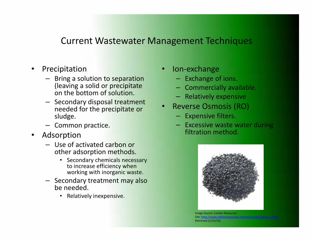
Current Wastewater Management Techniques
• Precipitation– Bring a solution to separation
(leaving a solid or precipitate on the bottom of solution.
– Secondary disposal treatment needed for the precipitate or sludge.
Common practice.
• Ion-exchange– Exchange of ions.
– Commercially available.
– Relatively expensive
• Reverse Osmosis (RO)– Expensive filters.
– Excessive waste water during – Common practice.
• Adsorption– Use of activated carbon or
other adsorption methods.• Secondary chemicals necessary
to increase efficiency when working with inorganic waste.
– Secondary treatment may also be needed.
• Relatively inexpensive.
– Excessive waste water during filtration method.
Image Source: Carbon Resources
Site: http://www.carbonresources.com/activated-carbon-1.html
Retrieved (2/24/10).

Wastewater Management
• Closed-Loop systems are ideal.
– Auxiliary tanks used to bring used solution up to quality, useable solution.quality, useable solution.
• Trivalent chromium turned back to hexavalentthrough low current electrodeposition.
• All other unusable solution treated.
Image Source: Steves Plating Corporation, “Chrome Plating” (2010).
Site: www.stevesplating.com/chrome_plating.htm (Retrieved 2/24/20).
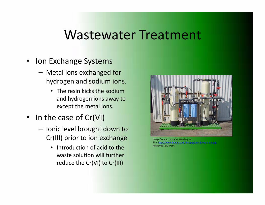
Wastewater Treatment
• Ion Exchange Systems
– Metal ions exchanged for
hydrogen and sodium ions.
• The resin kicks the sodium
and hydrogen ions away to
except the metal ions.except the metal ions.
• In the case of Cr(VI)
– Ionic level brought down to
Cr(III) prior to ion exchange
• Introduction of acid to the
waste solution will further
reduce the Cr(VI) to Cr(III)
Image Source: La Habra Welding Inc.
Site: http://www.lhwinc.com/images/ion%20exchange.jpg
Retrieved (2/26/10).

Ionic Exchange (cont’d)
• Regenerant– The metal pulled out of the
wastewater encapsulated into the resin.
• Regenerant Recycling Options
• Electrowinning– Plating the removed metal
onto cathode plates for disposal.
• Further DI/RO (De-Ionized/Reverse Osmosis) Options
– Evaporation .
– Precipitation.
– Electrowinning.
– Disposing to secondary recycling facilities.
Ionized/Reverse Osmosis) treatments may be needed for municipal sewer return to reach proper TDS (total dissolved solids) levels.
• Also ppm levels need to be achieved (Cr).

Future Remediation Processes
• Photocatalytics
– The use of
photocatalysts have
grown in the air filtration
industry.industry.
• Other industries draw to
the possibilities.
• Biofiltration
Image Source: Filter Innovations Inc.
Site: http://www.filterinnovations.com/applications.php?application=4
Retrieved (2/24/10).

Photocatalytics
• Use of with citric
acid creates electron-
hole pairs that generate
free radicals.
TiO2
Image Source: Photo-Catalytic Materials Inc. (2005).
Site: http://www.photocatalyst.co.jp/e/toha/toha.htm (Retrieve 2/24/10).
• The free radicals
breakdown the metal
ions and release by-
products in return
(carbon dioxide and
water).
Site: http://www.photocatalyst.co.jp/e/toha/toha.htm (Retrieve 2/24/10).
Image Source: Hygien Tech
Site: http://www.shoeracks.co.kr/eng_tech2.php
Retrieved (2/26/10).
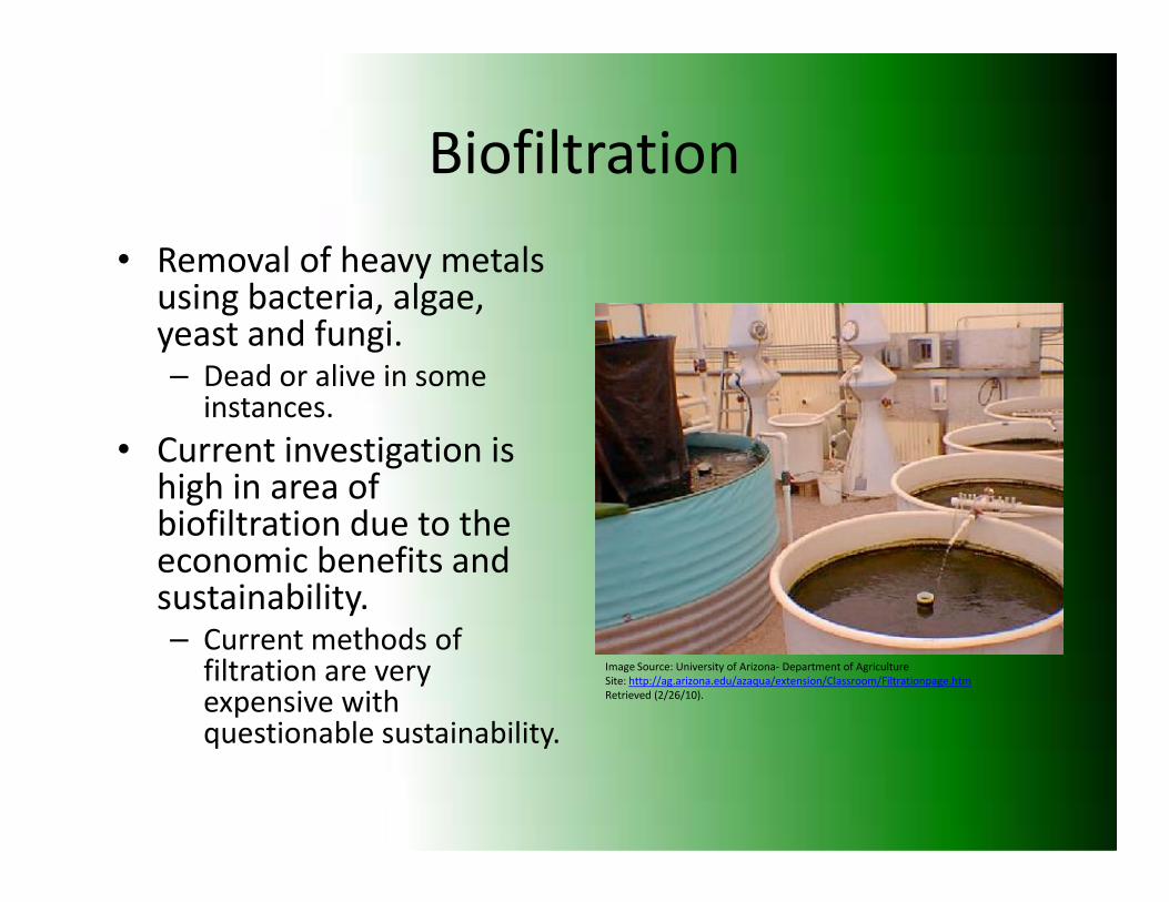
Biofiltration
• Removal of heavy metals using bacteria, algae, yeast and fungi.– Dead or alive in some
instances.
• Current investigation is • Current investigation is high in area of biofiltration due to the economic benefits and sustainability.– Current methods of
filtration are very expensive with questionable sustainability.
Image Source: University of Arizona- Department of Agriculture
Site: http://ag.arizona.edu/azaqua/extension/Classroom/Filtrationpage.htm
Retrieved (2/26/10).

Future Processes
• Trivalent chromium
• HVOF spray coatings
• PVD coatings
Image Source: Deloro Stellite, “HVOF- High Velocity Oxy Fuel” (2010). Image Source: Deloro Stellite, “HVOF- High Velocity Oxy Fuel” (2010).
Site: www.stellite.co.uk/.../tabid/76/Default.aspx (Retrieved 2/24/10).
Image Source: PVD, “ An example of a PVD vacuum coating machine, (2010).
Site: http://www.pvd-coatings.co.uk/coating-machine.htm (Retrieved 2/24/10).

Trivalent Chromium
• Trivalent chromium has been used for many years in the decorative industry.
• Major hurdle has been the ability to increase the
• A few companies have developed proprietary solutions with the incorporation of ligandsand complexants to increase the
the ability to increase the plating thickness while still maintaining the bath sustainability.
increase the sustainability.
– Still has not been widely proven to eliminate the neutralization of the bath which inhibits the baths production sustainability.

HVOF Coatings
• High Velocity Oxy-Fuel (HVOF)
– High pressure, dry coating using the combustion of a fuel
• The coating has promising end-of-life removal potential.
– The electrolytic removal method is chemically combustion of a fuel
(hydrogen, butane, etc.).
– Powder is deposited at high pressure and velocity in melted form.
• Aerospace and DoD are investigating the use of HVOF, heavily.
method is chemically benign.
Image Source: University of Toronto, Center for Advanced Coating Technologies (2010).
Site:www.mie.utoronto.ca/.../CACT-Facilities.html. (Retrieved 2/24/2010)

PVD Coatings
• Uses a physical process of evaporation or vaporization of a material.– Carried out under a
vacuum condition.
• The vaporized coating is transported and may entail a series of reactions onto the workpiecesurface.– Deposition occurs to the vacuum condition.
– Solid material is bombarded with high energy.
• This energy vaporizes the material on the atomic level.
– Deposition occurs to the workpiece
• Coatings are currently developed to be as hard as chrome. Some including chromium for a similar visual appeal.– Process is expensive.

Implementation
• Assessment of partners current operations.– Create an outline of areas to
investigate.
• Review available technology for implementation to their operations.
• Work collaboratively with partner to develop a plan of action.
• Start conducting cost analysis breakdowns vs. environmental benefits.– Provide implementation plans operations.
– Trivalent chrome process
– Ion exchange
– Suppressant solutions
– HVOF
• Assess Application– Do new technologies fit with
Ottawa’s product line?
– Cost effective.
– Provide implementation plans to partner for evaluation.
• Implement small scale studies/research if applicable.– Possibilities include:
• Biofiltration
• Photocatalytics
• Ion-Exchange, etc.
• Energy Analysis of Operations

Thank You
• Questions?
Image Source: Chrome That Hog “Production” (2010)
Site: www.chromethathog.com/production.html (Retrieved 2/24/20010)
Image Source: “Celebrate Green Week With The Rubicon Project” (2009).
Site: http://www.rubiconproject.com/blog/culture/?m=200905 (Retrieved 10/24/2010)