Green Energy Coastal Collection Operation - CAS – …my.fit.edu/~swood/GECCO FINAL REPORT...
88
Green Energy Coastal Collection Operation Chris Ellert Heather Weitzner Jeremy Sirois Luis Maristany Nicole Waters Virginia Tiede-Hutton
Transcript of Green Energy Coastal Collection Operation - CAS – …my.fit.edu/~swood/GECCO FINAL REPORT...

Green Energy Coastal Collection Operation Chris Ellert Heather Weitzner Jeremy Sirois Luis Maristany Nicole Waters Virginia Tiede-Hutton

ii
TRANSMITTAL Florida Institute of Technology Department of Marine and Environmental Systems TO: Dr. Stephen Wood Department of Marine and Environmental Systems Florida Institute of Technology 150 West University Blvd. Melbourne, FL 32901 FROM: Team GECCO: Ocean Energy System Department of Marine and Environmental Systems 150 West University Blvd. Melbourne, FL 32901 RE: Final Design Report SUBMITTAL DATE: May 6, 2011 Dr. Wood, Please review the attached Final Design Report for the “GECCO” Ocean Energy System.
Chris Ellert Heather Weitzner
Jeremy Sirois Luis Maristany Nicole Waters
Virginia Hutton

iii
Table of Contents Acknowledgements……………………………………………………………………………………......3 Executive Summary………………………………………………………………………………………4 Introduction…………………………………………………………………………………………….....5 Purpose…………………………………………………………………………………………………....5 Goals…………………………………………………………………………………………………..….5 Background and History……………………………………………………………………………..…...6 Design Concept……………………………………………………………………………………..….....8 Research and Initial Design………………………………………………………….……………..……..9 Initial Design………………………………………………………………….…………..……...9 Duck Design………………………………………………………………….…………..……....9 Joint Design………………………………………………………………….………………….10 Body………………………………………………………………………….………………....10 Ribbing…………………………………………………………………………………….……12 Flanges…………………………………………………………………………………….…....13 End Caps……………………………………………………………………………..................14 Hydraulics………………………………………………………………………………….…...14 Mooring Design…………………………………………………………………………………….……15 Buoyancy…………………………………………………………………………………………….…..17 Manufacturing………………………………………………………………………………………..…..18 Safety Precautions………………………………………………………………………….…...18 Materials Selection………………………………………………………………………………………19 Body…………………………………………………………………………………………….19 Joints……………………………………………………………………………….....................21 Joint Shaft………………………………………………………………………………………22 Ducks………………………………………………………………………………...................23 Hardware……………………………………………………………………………………….26 Assembly and Disassembly……………………………………………………………………………..27 Ducks……………………………………………………………………………………………27 Joint……………………………………………………………………………………………..28 Internal Components…………………………………………………………………………...29 Cruise…………………………………………………………………………………………………….29 Transportation………………………………………………………………………..................30 Deployment……………………………………………………………………………………..31 Observational Analysis…………………………………………………………………………33 Results……………………………………………………………………………………………………34 Budget……………………………………………………………………………………………………36 Monetary Investments………………………………………………………………………....................36 Conclusion………………………………………………………………………………………………..37 References………………………………………………………………………………………………..38 Appendices……………………………………………………………………………………………….39 Appendix A: Safety Plan……………………………………………………………...................39 Appendix B: Work Hours………………………………………………………………………..49 Appendix C: Budget……………………………………………………………………………..50 Appendix D: Cruise Report……………………………………………………………………...53 Appendix E: Calculations……………………………………………………………………….88

List of Figures Figure 1: Pelamis Wave Energy Converter…………………………………………………………..…..7 Figure 2: Salter Duck………………………………………………………………………………..……7 Figure 3: GECCO Design Concept…………………………………………………………………..…..8 Figure 4: Duck Design………………………………………………………………………………..…..9 Figure 5: Joint Design………………………………………………………………………………...…10 Figure 6: Blue/Green Project…………………………………………………………………………….11 Figure 7: GECCO Main Body Section…………………………………………………………………..11 Figure 8: Ribbing………………………………………………………………………………………...12 Figure 9: Brass Bearings…………………………………………………………………………………13 Figure 10: Flanges………………………………………………………………………………………..13 Figure 11: End Caps……………………………………………………………………………………...14 Figure 12: Hydraulics System Layout…………………………………………………………………...15 Figure 13: Mooring Side View…………………………………………………………………………...16 Figure 14: Mooring Top View……………………………………………………………………………17 Figure 15: Using the Respirators…………………………………………………………………………19 Figure 16: Coating the Fiberglass Pipes…………………………………………………………………..20 Figure 17: Aluminum Ribbing…………………………………………………………………………….20 Figure 18: Aluminum Joint………………………………………………………………………………..21 Figure 19: Cutting Delrin Spacers………………………………………………………………………...22 Figure 20: Joint Shaft……………………………………………………………………………………..22 Figure 21: Ducks Moving in the Water…………………………………………………………………...23 Figure 22: Shaft Seals……………………………………………………………………………………..24 Figure 23: Duck Flanges…………………………………………………………………………………..24 Figure 24: Plywood Ribbing………………………………………………………………………………25 Figure 25: Fiberglassing the Ducks……………………………………………………………………….25 Figure 26: Stainless Steel Hardware on Joint Plate………………………………………………………27 Figure 27: Assembling the Ducks………………………………………………………………………...28 Figure 28: Assembling the Joint…………………………………………………………………………..28 Figure 29: Fitting the Ribbing…………………………………………………………………………….29 Figure 30: GECCO System for Deployment…………………………………………………………......30 Figure 31: Trailering the GECCO………………………………………………………………………..31 Figure 32: Deploying the GECCO……………………………………………………………………….32 Figure 33: Obtaining Videos and Pictures………………………………………………………………..33 Figure 34: Waves approaching the GECCO……………………………………………………………...35
3
Acknowledgements
Thank you to Florida Institute of Technology and the Department of Marine and
Environmental Systems for their support and resources that allowed us to design and
manufacture our system. We would like to extend our gratitude to Industrial Plastic Systems,
Inc., Precision Fabricating and Cleaning, Dr. Geoffrey Swain, and Victoria Camp for their
generosity and contributions to our project. Finally we would like to thank Dr. Stephen Wood,
Dr. Ron Reichard, Dr. Steven Jachec, Dr. Chelakara Subramanian, Tonya Mitchell, Bill Bailey,
Bill Batten, and Jim Tryzbiak for their mentorship.
4
Executive Summary Florida Tech’s GECCO team began the research and development for the ocean energy
system in December 2010. The objective of the GECCO project is to create an alternative energy
source that is not oil or gas dependent. The system is intended to ride along ocean waves, while
employing the motion of the ducks and spine to produce pressurized hydraulic fluid. The
pressurized fluid is then released into a turbine which creates electrical energy. The spine
utilizes the vertical motion of the swell to push and pull a hydraulic piston. Smaller waves cause
the ducks to rotate while a pump converts the rotational energy from the ducks into pressurized
hydraulic fluid. Both systems act in unison to build hydraulic pressure until it can be released
into an electric turbine.
Waves carry a significant amount of energy, the ability to capture this energy is
especially appealing because not only is it environmentally safe, but the energy is continuously
created whereas wind and solar devices are highly weather dependent.
Testing occurred on the Marine Field Projects cruise to test the structural intergrity and
movement of the GECCO. The A-frame aboard the RV Thunderforce was utilized to deploy and
recover the GECCO. Divers secured three sand screws in a triangular shape at the seafloor and
three mooring lines were then shackled together at a mooring buoy, then to the GECCO. After
the cruise was completed, the videos obtained were analyzed to determine the rotational
velocities of the ducks, as well as the translational velocity of the joint. This data was used to
calculate the energy and power output of the GECCO using the Mechanical Energy equation:
346 kWh/year. This value was determined using average summer wave conditions, and is based
on only the ducks’ rotation.
The total budget for the GECCO was $4,500.00. Thus far $4070.44 has been spent in
supplies to create the shell of the system, the hydraulics have yet to be added to the inside of the
spine. With additional funding, the rest of the system that was not completed for the cruise will
be constructed and implemented into the pre-existing prototype.

5
Introduction Florida Institute of Technology’s 2011 ocean energy group has worked for five months
designing and constructing the initial plans for the system and its deployment. Green Energy
Coastal Collection Operations is an alternative energy project capable of converting the
rotational and vertical motion of the ocean into usable electrical energy. It consists of three, ten
foot sections, attached by two finger joints. This portion of the system is known as the spine, and
utilizes the vertical wave motion. Attached to the spine are four, three-foot long ducks which
make use of the rotational motion. The entire system was deployed during the Marine Field
Projects cruise, and moored to the seafloor using sand screws. Ultimately, the energy of the
waves will be converted and stored as usable energy.
Purpose Today’s world is one in which the oil and gas industry plays a major role in energy
consumption. Nations depend heavily on these resources however they are not renewable and
have many disadvantages. The act of extracting oil is both costly and harmful to the
environment, as evident by past and present oil spills. Among other negative consequences,
natural gas contributes heavily to carbon emission, which is predicted to increase. New
technology must be developed to help wean nations off of oil and gas, or at least lessen their
consumption. GECCO is an ocean energy system intended to mitigate the pollution issues on a
small scale at first and eventually branch out to larger areas.
Goals The ocean is a major resource for all types of materials and supplies, however wave
energy has yet to be fully explored. Team GECCO has constructed an alternative energy system
independent of non-renewable resources, such as oil and gas. Theoretically, the system will be
able to harness the energy contained in the waves and convert it to usable electric energy. By
doing so, dangerous drilling and extraction can be avoided.

6
Background and History People have used renewable sources of energy for thousands of years; everything from
the use of a water wheel to grind wheat into flour to the invention of the sail, which
revolutionized trade and exploration. Nowadays engineers are trying to find new ways to harness
renewable sources of energy in order to meet the planet’s increase in demand. As of 2010 the
global oil consumption grew to a staggering 86.7 million barrels per day (bbl/d); and it’s
predicted that by 2012 the total world consumption rate will grow to 89.7 million [2]. Our goal,
along with many others, is to reduce the dependency on these nonrenewable resources. The
ocean itself holds an enormous amount of energy that can be captured; it is anticipated that using
1/1000th of the existing energy in the Gulf Stream could supply the state of Florida with 35% of
its electrical needs [4]. The ocean energy team’s prototype seeks to harness the power stored in
ocean waves and effectively produce useful amounts of electricity. Before introducing the details
of the ocean energy design, important information about other wave energy devices must be
introduced.
One of the existing devices that serve as a source of inspiration is the Pelamis Wave
Energy Converter seen on the following page; this device is 180m long and is divided into 4
sections that are allowed to freely move with the ocean surface. The up and down movement
created by the waves is then transferred to the Pelamis and converted into electrical energy by
generators within the sections. According to the creators of Pelamis each machine is rated to
produce up to 750kW but on average depending on sea conditions it produces 25-40% of its full
capacity [4]. The wave energy prototype harnesses the vertical motion of ocean waves and
converts it to electrical energy in a similar fashion.

7
The next device that must be
discussed in this report is the Salter
Duck (pictured on the left) because it is
the prototype of this device that
inspired the full design of the Ocean
energy team prototype. The Salter
Duck was originally designed in 1976
and created by the Edinburgh Wave
Power group led by Stephen Salter of
Edinburgh University. The Salter Duck is a
teardrop shaped wave terminator system
oriented perpendicular to the direction of the wave with the nose of the teardrop facing the
oncoming wave. The devise was designed to rotate and “bob” up and down as a wave passes.
The bobbing and rotating motion is used to pump hydraulics, which drives an electrical
generator. This design allows the Salter Duck to be highly efficient in extracting energy from
the transverse motion of the waves [7].
Figure 2: Salter Duck (http://permaculture.org.au/2010/02/23/wave-power/)
Figure 1 : Pelamis Wave Energy Converter (http://www.pelamiswave.com/wp-content/uploads/2010/12/Winter-install.jpg)

8
Advantages of the Salter Duck include its high efficiency and its small size. The Salter
Duck has an efficiency of 80 to 90%. For a wave with 96% energy going into the Salter Duck,
the duck will absorb 90% of the energy by the bobbing and rotating motion. Only 6% of wave
energy is lost due to viscous friction [7]. Due to the small size of the duck, many Salter ducks
can be placed in a small area, which allows more energy to be harnessed from the ocean waves
[6].
Design Concept Project GECCO is made up of three ten-foot sections of fiberglass pipe connected by two
joints that bend vertically. As a wave passes, a pulley system attached to the joint translates the
motion of the wave into pumping of the hydraulic cylinders. Similarly, ducks are attached next to
the joint; which bend horizontally in a back and forth motion. The motion that the joints and
ducks have will allow hydraulic fluid to be pumped into an accumulator; once the accumulator
reaches a maximum pressure the fluid will drive a turbine creating electricity. The estimated
weight of the system is about 3,016 lbs with a 1 ft. draft. Our design concept of the body can be
seen in Figure 3.
Figure 3: GECCO Design Concept

9
Research and Initial Design
Initial Design The design of this system focuses on combining two existing methods for extraction of
wave energy similar to the Pelamis and Salter’s Duck, to create a revolutionary wave energy
extraction system. The initial design focuses on creating a platform that can sustain both systems
and allow them to work in unison. The final system must be resilient enough to withstand the
harsh marine environment for the time of deployment and testing and the final system must be
able to survive in the marine environment for extended periods of time and is why material
selection is a crucial part of this design. Below is a list of every major component of the system
with an explanation of the specifics for each individual part.
Duck Design The Salter duck will extract
the smaller gravity waves and or
portions of the passing swells. The
Salter duck can be sized according to
the size of waves the duck will
encounter. We have designed our
system to use ducks three feet in
length to extract energy from small
waves, one to two feet in wave
height. It was observed that a weight
was needed to keep the duck in the
optimal position for each approaching wave. To keep the duck upright, a series of holes were
designed to hold PVC pipes. These pipes hold sand to provide a counter weight to the duck. A
stainless steel shaft is attached to all four of the ducks; the shafts are connected to the ribbing by
the use of custom-made aluminum flanges that bolt to the plywood as well as the stainless steel
shaft. Stainless steel was chosen because of its resistance to corrosion and high strength. Two of
Figure 4: Duck Design (https://sites.google.com/a/my.fit.edu/wet/)
10
the ducks have longer shafts that run through the entirety of the main body section and attach to
the other two ducks with steel connectors that slide over the shaft and bolt to them.
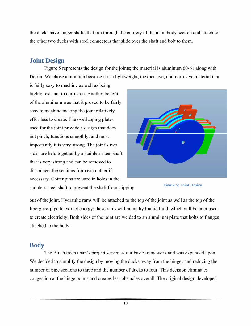
Joint Design Figure 5 represents the design for the joints; the material is aluminum 60-61 along with
Delrin. We chose aluminum because it is a lightweight, inexpensive, non-corrosive material that
is fairly easy to machine as well as being
highly resistant to corrosion. Another benefit
of the aluminum was that it proved to be fairly
easy to machine making the joint relatively
effortless to create. The overlapping plates
used for the joint provide a design that does
not pinch, functions smoothly, and most
importantly it is very strong. The joint’s two
sides are held together by a stainless steel shaft
that is very strong and can be removed to
disconnect the sections from each other if
necessary. Cotter pins are used in holes in the
stainless steel shaft to prevent the shaft from slipping
out of the joint. Hydraulic rams will be attached to the top of the joint as well as the top of the
fiberglass pipe to extract energy; these rams will pump hydraulic fluid, which will be later used
to create electricity. Both sides of the joint are welded to an aluminum plate that bolts to flanges
attached to the body.
Body The Blue/Green team’s project served as our basic framework and was expanded upon.
We decided to simplify the design by moving the ducks away from the hinges and reducing the
number of pipe sections to three and the number of ducks to four. This decision eliminates
congestion at the hinge points and creates less obstacles overall. The original design developed
Figure 5: Joint Design

11
by the Blue/Green team (Figure 6) and the main section of team GECCO’s design (Figure 7) are
shown on the following page [6].
Figure 6: Blue/Green Project
Figure 7: GECCO Main Body Section
The Final design for the body uses ten-foot sections of two-foot diameter fiberglass pipe.
These pipes are lightweight and very strong and most importantly are impervious to corrosion.
The purpose of the body sections is to provide a platform to contain all of the systems and
provide enough buoyancy to maintain them above the surface. The body is designed to be
completely water tight but some systems were installed in case a leak did occur these systems
include the installation of an automatic bilge pump as well as inserting foam within the pipe to
add buoyancy in case the system floods. Holes were placed along the body section to allow for

12
the duck shafts to run through the body and rest above the waterline when the system is placed in
the ocean.
Ribbing
Within the body of the GECCO there is a square ribbing system mounted on tracks that
support the structure as seen in Figure 8. The track system is welded to the end caps to ensure the
system remains aligned as well as holding the flanges and the end caps in place and distributing
the forces on the joint throughout the entire body. This ribbing functions as structural
reinforcement to the pipe as well as providing a rigid platform to mount all of the mechanical
systems within the GECCO; it is composed of aluminum because it provides a lightweight
corrosion resistant structure that is strong enough to perform the ribbing’s purpose adequately. A
square ribbing was chosen because it is relatively simple to manufacture and still provides
sufficient rigidity and strength to the structure. The track system allows the ribbing to slide out of
the body with little effort making repairs to internal components possible without completely
disassembling the entire body. Bolted to an L shaped piece of aluminum are four brass bearings,
which are then welded onto the inner side of the ribbing. The duck shafts are inserted through
these bearings which distributes the forces on the ducks throughout the ribbing and not the
fiberglass pipe. Distributing the weight evenly prevents any concentrated loads, which can break
the fiberglass pipe. The bearings can be seen in Figure 9.
Figure 6: Ribbing
13
Figure 9: Brass Bearings
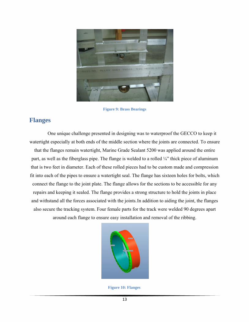
Flanges
One unique challenge presented in designing was to waterproof the GECCO to keep it
watertight especially at both ends of the middle section where the joints are connected. To ensure
that the flanges remain watertight, Marine Grade Sealant 5200 was applied around the entire
part, as well as the fiberglass pipe. The flange is welded to a rolled ¼” thick piece of aluminum
that is two feet in diameter. Each of these rolled pieces had to be custom made and compression
fit into each of the pipes to ensure a watertight seal. The flange has sixteen holes for bolts, which
connect the flange to the joint plate. The flange allows for the sections to be accessible for any
repairs and keeping it sealed. The flange provides a strong structure to hold the joints in place
and withstand all the forces associated with the joints.In addition to aiding the joint, the flanges
also secure the tracking system. Four female parts for the track were welded 90 degrees apart
around each flange to ensure easy installation and removal of the ribbing.
Figure 10: Flanges

14
End Caps The end caps used for the GECCO were created using left over T6 6060-61 aluminum
from the flange pieces once they had been cut. Rolled pieces of aluminum were welded to the
flat plates. The end caps were compression fitted into the fiberglass tubing and secured using
Marine Grade Sealant 5200. This prevented leakage into the main body section as well as
strength at the ends of each section for mooring lines to be attached. Holes were drilled into each
of the end caps and U-bolts were bolted into the end caps to be used for the mooring lines to be
shackled to. The end cap is depicted in Figure 11.
Figure 11: End caps
Hydraulics Located in the body section of the GECCO, the hydraulics are the heart of the
system; they are used to extract the kinetic energy of the waves and convert it into useable
electrical energy. The hydraulic system is divided into two systems that extract the energy at the
ducks and the joint. A hydraulic ram is connected to the joint and to the body, as the wave hits
the system the joint causes the hydraulic ram to contract and then retract; this motion pumps
hydraulic fluid into an accumulator tank. Once the accumulator tank reaches the designated
pressure it releases the hydraulic fluid into a turbine, which then creates the electricity.
The other component of the hydraulic system utilizes the rotation of the duck to pump
more hydraulic fluid through the system. The ducks connect via chains to a gear that is attached

15
to a hydraulic pump. A one way bearing is attached to the gears in order to allow for positive net
movement of the hydraulic pump; as the duck is rotated by a wave it rotates the pump, which in
turn moves hydraulic fluid through the system. Both the joint and the ducks contribute hydraulic
pressure to the system and run the turbine in unison. It is important to note that the hydraulics
have not been installed into the current prototype, but once the necessary funding is acquired he
hydraulics can then be installed. A preliminary hydraulics design setup is depicted in Figure 12
below.
Figure 12: Hydraulics System Layout
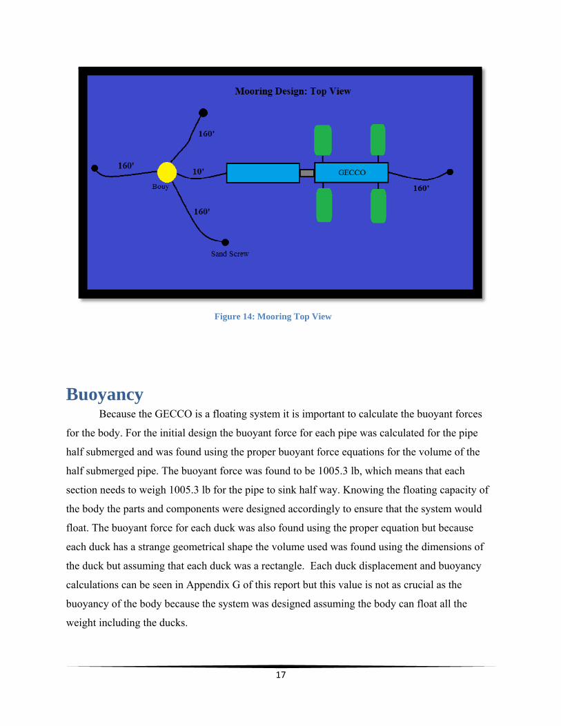
Mooring Design The following mooring system was created for the correct amount of force produced by
the GECCO and created using centenary calculations. One hundred pounds of force used was for
the catenary calculations. This value was determined using the average ADCP value for water
column velocity for the location of deployment. Dr. Steven Jachec provided the data used and it
should be noted that this was a generalized value subject to change. To prevent failure of the
system a factor of safety was added to the calculations and that provided the one hundred pound
value. The tripod design of the mooring system is meant to keep the GECCO in one location
while allowing it to ride the waves unhindered. The back line is meant to provide the GECCO a
slight rotation with the motion of the waves and the changing of the currents to a new angle of
fifteen degrees in either the clockwise or counter clockwise direction. From these calculations

16
the length of the rope needed, as well as the sand screw locations were determined. These
calculations can be located in Appendix G of this report.
Upon deployment, it was decided that the back line was unnecessary since the system
would align itself with the current and allowed for proper motion, since the current and waves
were initially facing the same direction. The mooring design worked very well in keeping the
system stationary while maintaining enough freedom to move with the waves, but it should be
noted that when the current direction was different than the wave direction it caused some
binding of the joint. For future designs a system to maintain the GECCO facing the waves at all
times needs to be created in order to ensure the maximum efficiency for the system. Both of the
mooring system designs are found in Figures 13 and 14 below.
Figure 73: Mooring Side View
17
Figure 14: Mooring Top View
Buoyancy Because the GECCO is a floating system it is important to calculate the buoyant forces
for the body. For the initial design the buoyant force for each pipe was calculated for the pipe
half submerged and was found using the proper buoyant force equations for the volume of the
half submerged pipe. The buoyant force was found to be 1005.3 lb, which means that each
section needs to weigh 1005.3 lb for the pipe to sink half way. Knowing the floating capacity of
the body the parts and components were designed accordingly to ensure that the system would
float. The buoyant force for each duck was also found using the proper equation but because
each duck has a strange geometrical shape the volume used was found using the dimensions of
the duck but assuming that each duck was a rectangle. Each duck displacement and buoyancy
calculations can be seen in Appendix G of this report but this value is not as crucial as the
buoyancy of the body because the system was designed assuming the body can float all the
weight including the ducks.

18
Once the system was built it was important to make sure the system floated horizontally
on flat water. To ensure that the system floated perfectly horizontally the longitudinal stability
for the body was calculated and it was determined that weight needed to be added to each end of
each section to compensate for the weight of the joint at the middle. The weight was added by
inserting sand bags in the pipe and tightly securing them to ensure that they remain in the proper
location. The weight of the sand needed was determined using the weight of the joint on either
end of the pipe and assuming that weight was what needed to be countered on the far side of the
pipe. The assumptions made are correct because the pipe is symmetrical and the other weights
inside are negligible when compared to the weight of the joint. The weight used for the sandbags
was correct and this became evident during the cruise when the system floated perfectly
horizontally in the water. When the GECCO was placed into the water the duck shafts were also
located above the waterline as we had originally calculated them to be.
Manufacturing:
Safety Precautions
Safety is a main concern during all phases of the project. During the manufacturing
phase safety was constantly considered. All machining of aluminum, plastic and fiberglass was
done with proper personal protective equipment (PPE). This was performed with proper eye
protection and respirators or dust masks when needed. Closed toe shoes were worn at all times
when machining. Loose clothing is not permitted near fast moving machinery such as saws,
drills, sanders and lathes. Ear protection was used if needed when working with machinery.
When handling harmful substances gloves were worn. MSDS sheets were present and readily
available at all times when working with any material that could possibly cause a health hazard.
All team members were educated on the different materials that will be used during the project.
Any person working with fiberglass material or have any chance of being exposed to an airborne
agent was trained and equipped with a respirator and worked in a well-ventilated area. Usage of
the respirators is demonstrated below in Figure 15 when one of the team members had to grind
off fiberglass.

19
Figure 15: Using the Respirators
The deployment and testing phase of the device also poses many safety risks that were
considered and planned for. Deployment plans and restrictions were created and followed. If
certain restrictions are not met, such as the wave heights are larger than planned for, the device
will not be deployed. The GECCO was not to be deployed in wave heights larger than two feet.
Divers are used to secure the device to the sea floor; therefore dive plans were created and
approved before any divers are allowed in the water. Divers also had to practice inserting sand
screws into the ground underwater before they were to deploy the GECCO and install the
moorings at Ft. Pierce. All divers are AAUS certified and have completed all necessary training.
Materials Selection Body
Fiberglass piping was chosen for its qualitative and quantitative characteristics. It is
lightweight and has a high durability. It also has a high yield strength and modulus of elasticity.
Although the price of fiberglass is steadily increasing due to the costs associated with coating it,
it is the best choice due to the nature of the project. The GECCO system is meant to be a green
energy system and this non-corrosive material will not require bio-fouling adhesives as would
steel or aluminum pipe. Garage floor epoxy was used as a top coating for the fiberglass pipes and
is depicted in Figure 16 as the teal color of the fiberglass piping. This coating prevented water
from getting into the fibers as well as the pipe to be more manageable when handled.
20
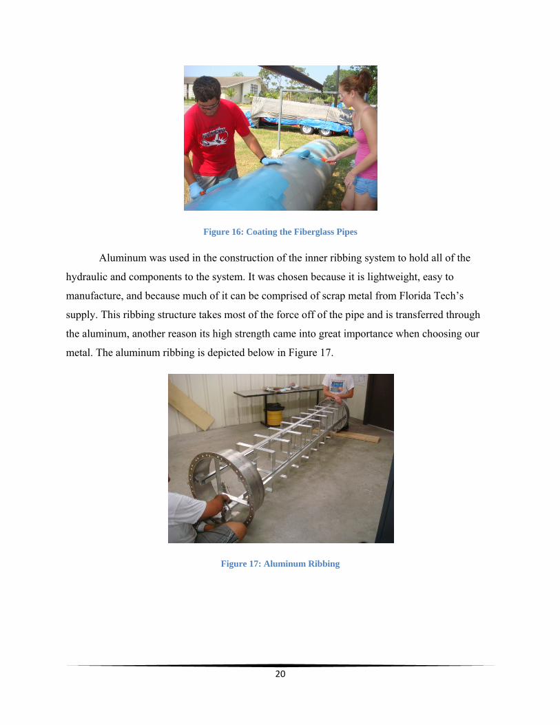
Figure 16: Coating the Fiberglass Pipes
Aluminum was used in the construction of the inner ribbing system to hold all of the
hydraulic and components to the system. It was chosen because it is lightweight, easy to
manufacture, and because much of it can be comprised of scrap metal from Florida Tech’s
supply. This ribbing structure takes most of the force off of the pipe and is transferred through
the aluminum, another reason its high strength came into great importance when choosing our
metal. The aluminum ribbing is depicted below in Figure 17.
Figure 17: Aluminum Ribbing

21
Joints
Aluminum joints have been chosen for easy construction of the joint under the current
time and financial restraints. Aluminum is lighter than steel, thus a steel joint would be much
heavier; aluminum is also less susceptible to corrosion than steel and less money needs to be
invested in cathodic protection. For the resources of Florida Tech’s machine shop aluminum is
easier to machine and weld than steel, thus an aluminum joint can be manufactured much
quicker. The one drawback to using aluminum is that it is much weaker than steel, medium alloy
steel has a yield strength of approximately 79800 p.s.i. [5] where as the 6061-T6 aluminum used
for the joint has a yield strength of 45000 p.s.i. [1], but luckily for the purposes of the GECCO
the strength of aluminum exceeds the forces of the wave the GECCO was to encounter during its
deployment. The joint can be seen in Figure 18 below.
Figure 18: Aluminum Joint
Delrin was used as a lubricating spacer between the joints to ensure easy movement of
the parts and low friction without compromising strength and saving weight. The Delrin also
does not corrode making it ideal for the marine environment; also, the introduction of Delrin into
the joint proved cost effective because it was donated to the team. The Delrin was soft enough to
be machined down on the lathe to the proper thickness as each of the 5/8” thick aluminum pieces
placed on either sides of the Delrin. Some of the Delrin pieces already had holes too large in the
center, so aluminum circular pieces were custom made to compression fit into these holes. One
inch holes were drilled into these circular aluminum pieces for the shaft to go through the
22
entirety of the joint. The original Delrin donated was also too thick and since it is a starboard
plastic that is held together in pieces by a glue like resin, we had to saw through the resin until
the pieces broke apart. Cutting the Delrin spacers can be seen in Figure 19 below.
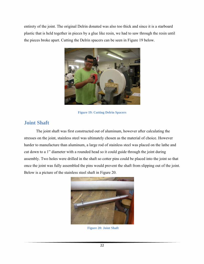
Figure 19: Cutting Delrin Spacers
Joint Shaft
The joint shaft was first constructed out of aluminum, however after calculating the
stresses on the joint, stainless steel was ultimately chosen as the material of choice. However
harder to manufacture than aluminum, a large rod of stainless steel was placed on the lathe and
cut down to a 1” diameter with a rounded head so it could guide through the joint during
assembly. Two holes were drilled in the shaft so cotter pins could be placed into the joint so that
once the joint was fully assembled the pins would prevent the shaft from slipping out of the joint.
Below is a picture of the stainless steel shaft in Figure 20.
Figure 20: Joint Shaft
23
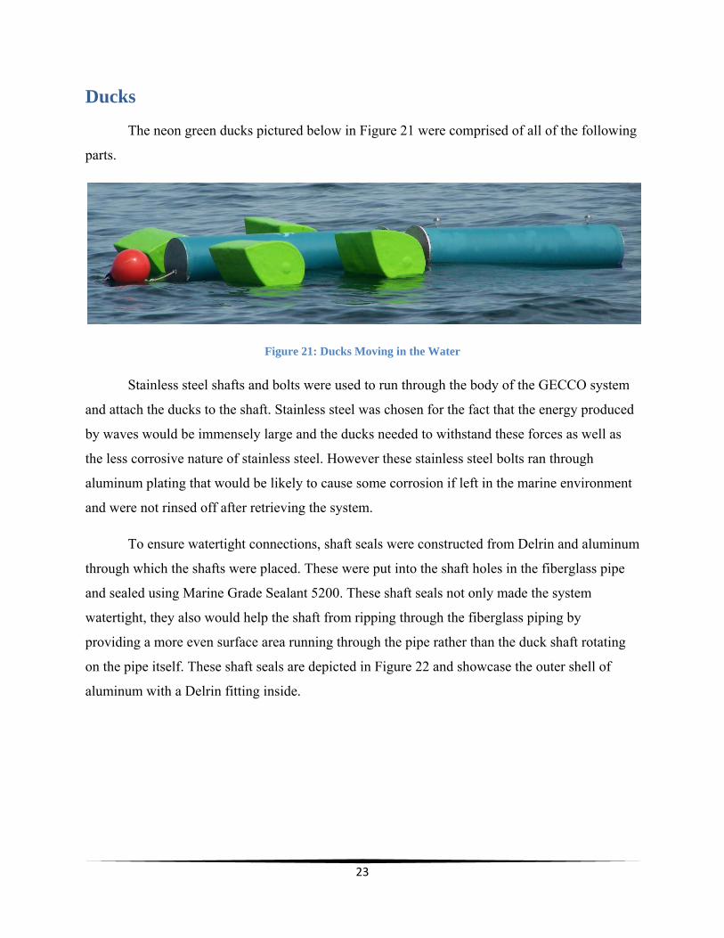
Ducks
The neon green ducks pictured below in Figure 21 were comprised of all of the following
parts.
Figure 21: Ducks Moving in the Water
Stainless steel shafts and bolts were used to run through the body of the GECCO system
and attach the ducks to the shaft. Stainless steel was chosen for the fact that the energy produced
by waves would be immensely large and the ducks needed to withstand these forces as well as
the less corrosive nature of stainless steel. However these stainless steel bolts ran through
aluminum plating that would be likely to cause some corrosion if left in the marine environment
and were not rinsed off after retrieving the system.
To ensure watertight connections, shaft seals were constructed from Delrin and aluminum
through which the shafts were placed. These were put into the shaft holes in the fiberglass pipe
and sealed using Marine Grade Sealant 5200. These shaft seals not only made the system
watertight, they also would help the shaft from ripping through the fiberglass piping by
providing a more even surface area running through the pipe rather than the duck shaft rotating
on the pipe itself. These shaft seals are depicted in Figure 22 and showcase the outer shell of
aluminum with a Delrin fitting inside.

24
Figure 22: Shaft Seals
Aluminum flanges were made for the ducks so they would be easy to weld and
manufacture. These supplies were also made from scrap metal in the machine shop. Rather than
use steel to weight the ducks down more the aluminum could be easily bolted to the plywood
ribbing. These flanges also had holes that were threaded so they would easily screw onto and
hold the stainless steel shaft in place. This idea is much like the idea of when a Christmas tree is
held into its stand. Once the ducks were fiberglassed these flanges would serve as merely
secondary structural supports. These flanges are depicted in Figure 23.
Figure 23: Duck Flanges
Plywood ribbing was used to support the structure of the duck and maintain its shape.
Plywood is affordable as well as easy to machine. Several holes were made in the top side of the
duck ribbing to decrease the weight of the ducks as well as provide buoyancy. The plywood
ribbing was covered in polyester resin to prevent the wood from swelling and to protect the wood
incase the ducks leaked during deployment of the GECCO system. The plywood ribbing was

25
assembled first with the stainless steel shaft and PVC piping running through it before being
fiberglassed as depicted in Figure 24.
Figure 24: Plywood Ribbing
Fiberglass sheets and polyester resin was used to create an overlying structure on top of
the ribbing to ensure a watertight structure. Lightweight cardboard was used to lie over the top of
the ribbing structure to improve the look and smoothness of the duck when the fiberglass was
placed on top. This will also enhance the look of the duck system and the hydrodynamics as a
wave passes by. Three layers of fiberglass were placed around the entirety of the ducks and two
layers were placed on each side of the ducks. Each of the edges also had multiple strips placed
on them. Polyester resin was chosen since it has a fast kick outdoors and would provide us with
the waterproofing we needed for deployment. The fiberglass could also be sanded and grinded
down as well as filled in so that the smoothness of the duck could be controlled for testing
purposes. Fiberglassing the ducks can be seen in Figure 25.
Figure 25: Fiberglassing the Ducks

26
Styrofoam was used to fill the ducks before they were sealed off. Styrofoam not only
gave the duck more weight but also increased the buoyancy of the ducks. The Styrofoam was
broken into small pieces and placed in each of the ribbing chambers to achieve even buoyancy in
all three ribbing chambers of the ducks. Styrofoam was also used since it was a donation
provided for by Dr. Wood. Styrofoam was also used to fill each of the body sections for similar
purposes.
PVC piping was used as a chamber for each of the counterweights of the ducks. Sand was
placed inside of these pipes that were cut to the length of the ducks. These counterweights act as
the restoring force for each of the ducks as a wave passes by so it can restore the ducks to their
original positions. PVC was also donated and was fiberglassed on each side so it remained water
tight and prevented the sand from falling out of the pipes.
Hardware
Stainless steel hardware was used everywhere on the system where something needed to
be bolted such as on the plate that connects the joint to the flanges, as well as the stainless steel
shaft that was used to connect both pieces of the joint together. Stainless steel was chosen
because of its high strength and high resistance to corrosion. It should be noted that combining
two dissimilar materials such as stainless steel and aluminum causes corrosion issues when in
saltwater and measures must be taken to prevent this by isolating the metals from each other and
installing cathodic protection measures such as sacrificial zinc anodes. These measures were not
taken for the initial GECCO system because they were not necessary due to the brevity of the
testing period and thus the system was not in the ocean long enough for corrosion to become
problematic. Anti-seize lubrication was also used for the stainless bolts since they often seize
when bolted through materials. The stainless bolts on the joint plate can be seen in Figure 26.

27
Figure 26: Stainless Steel Hardware on Joint Plate
Assembly and Disassembly
This section focuses on briefly describing the process for assembling the GECCO system
for deployment. The GECCO system is relatively simple to assemble and can be done in few
steps; as it sits now the prototype has only four Ducks and one joint that require any assembly.
Ducks
Two ducks have shafts that are inserted through the entirety of the body section and
should not be removed after the GECCO manufacturing is completed, but the two ducks with the
shorter shafts can be removed to make the system more compact and easier to handle. In order to
reconnect the ducks to the system the shaft connector can be bolted to one shaft while the other
duck is bolted to the other side of the connector piece. It is important to note that while the duck
shafts are connected to each other the ducks must line up with each other for proper operation; if
the holes on the shafts don’t allow for the ducks to line up then that is the wrong duck being
attached to the shaft. Each duck has to be connected to its corresponding shaft in order for the
duck system to function properly. Duck assembly can be seen in Figure 27 as the one duck is
being placed onto the duck shaft.
28
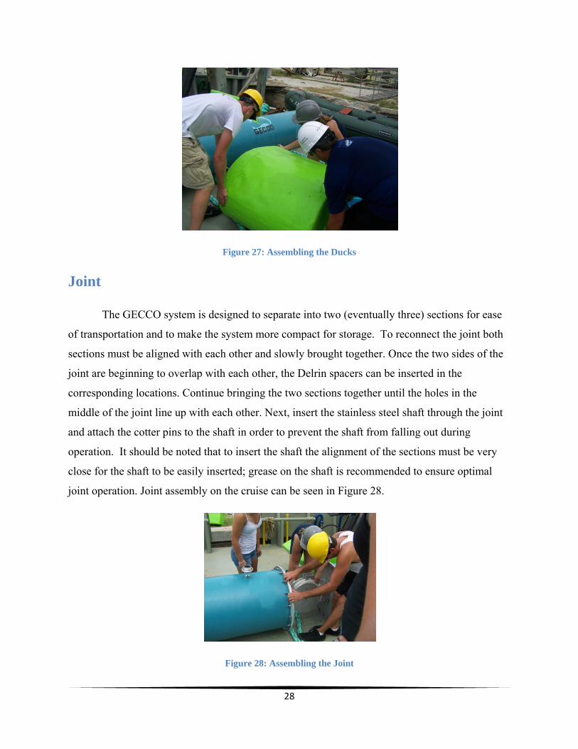
Figure 27: Assembling the Ducks
Joint
The GECCO system is designed to separate into two (eventually three) sections for ease
of transportation and to make the system more compact for storage. To reconnect the joint both
sections must be aligned with each other and slowly brought together. Once the two sides of the
joint are beginning to overlap with each other, the Delrin spacers can be inserted in the
corresponding locations. Continue bringing the two sections together until the holes in the
middle of the joint line up with each other. Next, insert the stainless steel shaft through the joint
and attach the cotter pins to the shaft in order to prevent the shaft from falling out during
operation. It should be noted that to insert the shaft the alignment of the sections must be very
close for the shaft to be easily inserted; grease on the shaft is recommended to ensure optimal
joint operation. Joint assembly on the cruise can be seen in Figure 28.
Figure 28: Assembling the Joint
29
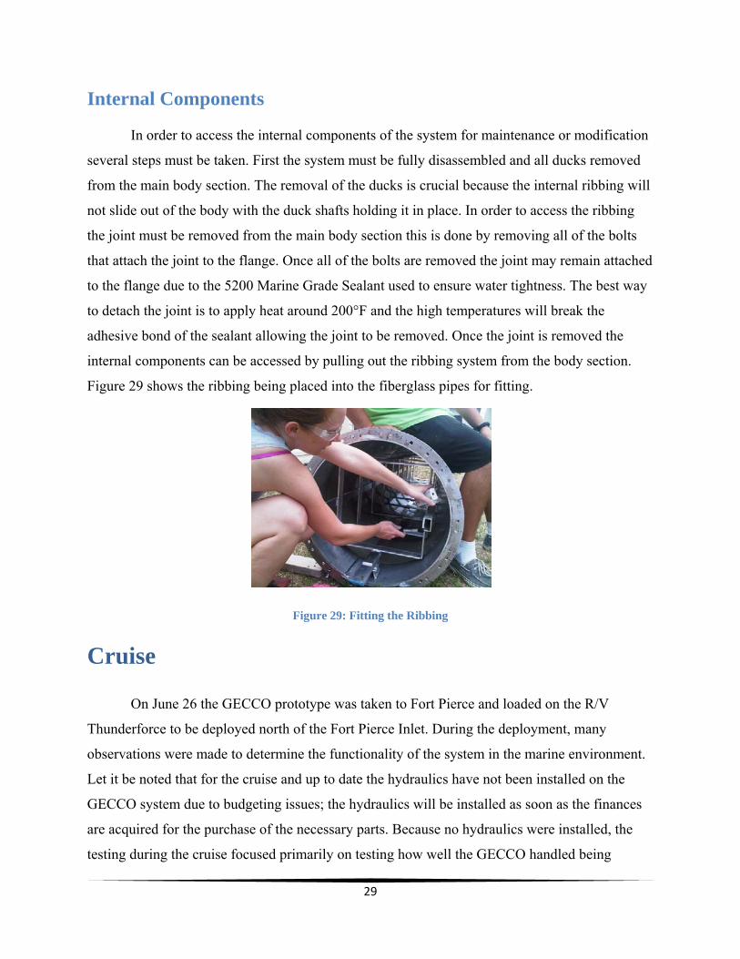
Internal Components
In order to access the internal components of the system for maintenance or modification
several steps must be taken. First the system must be fully disassembled and all ducks removed
from the main body section. The removal of the ducks is crucial because the internal ribbing will
not slide out of the body with the duck shafts holding it in place. In order to access the ribbing
the joint must be removed from the main body section this is done by removing all of the bolts
that attach the joint to the flange. Once all of the bolts are removed the joint may remain attached
to the flange due to the 5200 Marine Grade Sealant used to ensure water tightness. The best way
to detach the joint is to apply heat around 200°F and the high temperatures will break the
adhesive bond of the sealant allowing the joint to be removed. Once the joint is removed the
internal components can be accessed by pulling out the ribbing system from the body section.
Figure 29 shows the ribbing being placed into the fiberglass pipes for fitting.
Figure 29: Fitting the Ribbing
Cruise
On June 26 the GECCO prototype was taken to Fort Pierce and loaded on the R/V
Thunderforce to be deployed north of the Fort Pierce Inlet. During the deployment, many
observations were made to determine the functionality of the system in the marine environment.
Let it be noted that for the cruise and up to date the hydraulics have not been installed on the
GECCO system due to budgeting issues; the hydraulics will be installed as soon as the finances
are acquired for the purchase of the necessary parts. Because no hydraulics were installed, the
testing during the cruise focused primarily on testing how well the GECCO handled being

30
berated by the sea as well as observing the motions of the joint and the ducks with different wave
and current scenarios encountered during the testing period of approximately 24 hours. Also, for
the duration of the cruise only two body sections and one joint were constructed. This however
did not hinder any of the testing data and the motion of the GECCO was still able to be analyzed.
The testing was a success and hours of film were taken, observed, and analyzed. The video data
obtained was used to calculate a theoretical value for the energy extracted by the GECCO if the
hydraulics would have been installed. As well as video data the success of the cruise relied on
the deployment and retrieval of the GECCO with minimal damage to the system. The GECCO
was successfully retrieved and remains fully functional after being deployed and withstanding
harsh marine conditions. The system as it stood for deployment can be seen in Figure 30.
Figure 30: GECCO System for Deployment
Transportation
Due to the large size of the GECCO system, it became an issue of transportation. We
designed the sections to disassemble at the hinges to help ease in lifting and moving, however
each section still weighed over 300 lbs. To transport the system to Fort Pierce we had to use two
separate trailers, one for each section. A larger trailer was not used that would fit the entire
system already assembled due to the safety issues with transporting such a large item. Ratcheting
straps were used to secure the system to the trailer to prevent any shifting as well. The section
with four ducks attached had to be disassembled further in order for the section to fit on the
trailer. Two of the ducks were removed from the duck shaft and placed into the back of a truck
that trailered down the section of the GECCO with the ducks attached. Once the GECCO pieces

31
reached Fort Pierce the system was assembled on board the R/V Thunderforce. A crane was used
to lift and move the system from the trailers onto the R/V Thunderforce. In Figure 31 part of the
system being trailered down to Fort Pierce can be seen.
Figure 31: Trailering the GECCO
Deployment
Once the Thunderforce reached the deployment site at Fort Pierce, a quick survey of the
ocean floor was done to make sure the parameters of the mooring system and deployment was
met at a depth of nearly thirty feet. Once the survey was completed the dingy was sent out to
measure out where the sand screws for the mooring lines would be installed. Anchors were
attached to buoys then dropped at the sand screw sites for reference points for the divers that
were installing the sand screws. Divers were then deployed to install the sand screws and
connect the system. Once the divers connected the mooring lines to the sand screws the team
members assisting on the dingy connected the mooring lines to a center-mooring buoy. Once the
mooring system was set into place the deployment of the GECCO was next.
Two lifting straps were ran under the joint in the middle and two straps with hooks were
connected at both ends of the end caps to the U-bolts to prevent the system from bending when
lifted at the joint. All four straps were then connected to the A-frame. Before lifting two guiding
lines were tied to the front and the back of the system to help stabilize the system when lifted.
32
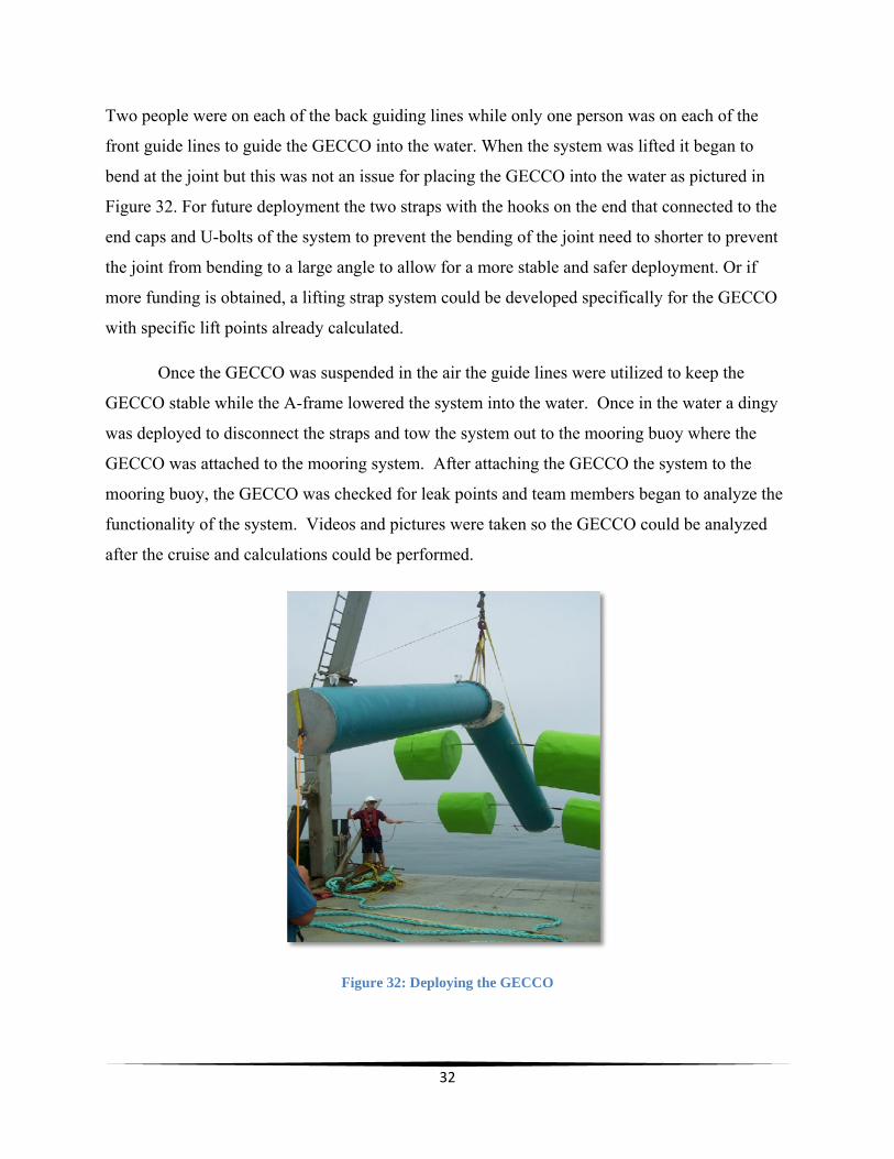
Two people were on each of the back guiding lines while only one person was on each of the
front guide lines to guide the GECCO into the water. When the system was lifted it began to
bend at the joint but this was not an issue for placing the GECCO into the water as pictured in
Figure 32. For future deployment the two straps with the hooks on the end that connected to the
end caps and U-bolts of the system to prevent the bending of the joint need to shorter to prevent
the joint from bending to a large angle to allow for a more stable and safer deployment. Or if
more funding is obtained, a lifting strap system could be developed specifically for the GECCO
with specific lift points already calculated.
Once the GECCO was suspended in the air the guide lines were utilized to keep the
GECCO stable while the A-frame lowered the system into the water. Once in the water a dingy
was deployed to disconnect the straps and tow the system out to the mooring buoy where the
GECCO was attached to the mooring system. After attaching the GECCO the system to the
mooring buoy, the GECCO was checked for leak points and team members began to analyze the
functionality of the system. Videos and pictures were taken so the GECCO could be analyzed
after the cruise and calculations could be performed.
Figure 32: Deploying the GECCO

33
Observational Analysis
During the duration of the GECCO’s deployment we took many videos, photos, and
personal accounts of the functionality of the GECCO. Our visual observations that were recorded
and theoretical calculations performed serve as the biggest form of data analysis for the GECCO
itself. Since there was not a hydraulic system during deployment of the GECCO system, most of
our data obtained was through observation. As the system initially went into the ocean the main
priority was to make sure all of the systems, such as the joint and the ducks, were functioning
properly and no major faults were present. More importantly, making sure the system was not
rapidly taking on water and sinking was crucial and this was done by watching the water line of
the GECCO and making sure it wasn’t changing and also by observing whether the bilge pump
inside the main body section was not pumping out water too frequently. It can be seen in Figure
33 of the team members approaching the GECCO to record video, pictures, and to check the
bilge pump for activation. Once it was clear that the system was functioning properly and no
imminent danger to the system was evident we could then record other observations such as
oceanographic data. Wave data such as average wave height, direction, and period were recorded
on the hour and video was recorded and later analyzed to determine the speed at which the ducks
and the joint were oscillating. This will further allow us to record theoretical data to be discussed
in the next section.
Figure 33: Obtaining Videos and Pictures
34
Results
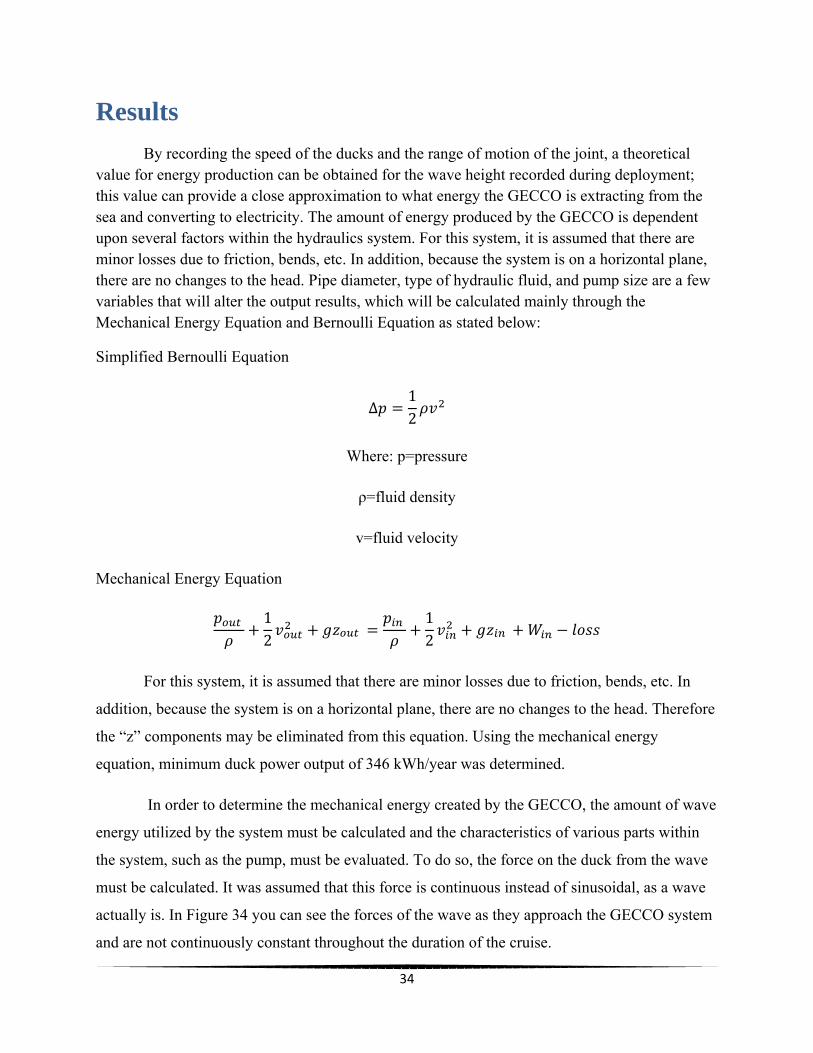
By recording the speed of the ducks and the range of motion of the joint, a theoretical value for energy production can be obtained for the wave height recorded during deployment; this value can provide a close approximation to what energy the GECCO is extracting from the sea and converting to electricity. The amount of energy produced by the GECCO is dependent upon several factors within the hydraulics system. For this system, it is assumed that there are minor losses due to friction, bends, etc. In addition, because the system is on a horizontal plane, there are no changes to the head. Pipe diameter, type of hydraulic fluid, and pump size are a few variables that will alter the output results, which will be calculated mainly through the Mechanical Energy Equation and Bernoulli Equation as stated below:
Simplified Bernoulli Equation
∆𝑝 = 12 𝜌𝑣
Where: p=pressure
ρ=fluid density
v=fluid velocity
Mechanical Energy Equation 𝑝 𝜌 + 12 𝑣 + 𝑔𝑧 = 𝑝 𝜌 + 12 𝑣 + 𝑔𝑧 + 𝑊 − 𝑙𝑜𝑠𝑠
For this system, it is assumed that there are minor losses due to friction, bends, etc. In
addition, because the system is on a horizontal plane, there are no changes to the head. Therefore
the “z” components may be eliminated from this equation. Using the mechanical energy
equation, minimum duck power output of 346 kWh/year was determined.
In order to determine the mechanical energy created by the GECCO, the amount of wave
energy utilized by the system must be calculated and the characteristics of various parts within
the system, such as the pump, must be evaluated. To do so, the force on the duck from the wave
must be calculated. It was assumed that this force is continuous instead of sinusoidal, as a wave
actually is. In Figure 34 you can see the forces of the wave as they approach the GECCO system
and are not continuously constant throughout the duration of the cruise.

35
Figure 34: Waves approaching the GECCO
Upon completion of the GECCO, various aspects of the system were calculated and
analyzed. Based on visual observations during testing the proper orientation of the system was
determined and the average power output was calculated. Initially the GECCO was placed in the
water in a way that allowed the joint to move freely, however the ducks did not rotate to their full
potential. When the system was revolved 180 degrees, the ducks rotated perfectly but the joint
did not undulate as well as initially. To allow both components to perform efficiently so the
maximum wave energy is extracted, the system must be angled between the two tested positions.
After the cruise was completed, videos of the testing were analyzed to determine the
rotational velocity of the ducks and the translational velocity of the joint. From this data the
revolutions per minute could be calculated which would then yield the flow rate and pressure
created by the pump and hydraulic system within the GECCO. These values, paired with the
torque applied to the ducks, provide the final power output of the system: 7.48 GWh/year. “The
average household in the United States uses about 8,900 kilowatt-hours of electricity each year”
[3], which means the system could power nearly one thousand homes a year through the ducks
alone. However, the assumptions made do not include frictional losses, bend and elbow losses of
the pipes, turbulence, or other realistic sources of energy depletion. The calculations are based on
summer conditions, during which wave heights are minimal. Given greater wave heights of the

36
winter months, the power output of the system would also be much greater. In addition, the
calculations do not include the power extracted by the joint, which is a major contributor to
energy collection. Calculations for energy output can be found in Appendix G.
Neither of these values is realistic and do not represent the actual power output of the
system. There are too many variables and complexities to obtain an accurate result. As the
project is furthered and another body section, joint, and hydraulics are added more data will be
able to be collected and examined for realistic energy outputs of the GECCO system.
Budget Courtesy of Northrop Grumman funding Florida Tech for their senior design “capstone”
projects, our budget initially was $4000.00. Precision Fabricating and Cleaning from Cocoa,
Florida donated $500.00 to our project. During the duration of construction $4070.40 was spent
on materials, construction costs, and another miscellaneous items needed for completion before
the cruise. This leaves the GECCO with $429.70 to be used in the following two semesters for
upkeep and further construction. With more funding, the third section and hydraulics will be
added to make a full GECCO prototype. For the breakdown of spending the budget can be found
in Appendix E of this report.
Monetary Investments Upon completion of the project, it was estimated that approximately $43,312.50 has been
invested by the team, assuming group members would be paid $50 per hour at a total of 866.25
man hours worked. The chart below details the amount of hours each member worked on the
project in the machine shop, however it does not include the time spent in meetings. If the
project was completed to its full potential the total monetary investment would increase to
approximately $100,000, and the amount of work hours would increase to over 2000. Aid was
also provided by professors and other Florida Tech faculty members, totaling 350.5 hours. Their
overall monetary investment, assuming they were paid $100 per hour, is $35,050.00. Therefore
the total investment in the project, had it been finished, would be over $150,000.00. This value
includes only work time in the machine shop and does not include the cost of parts or the cruise.

37
Conclusion Overall the Green Energy Coastal Collection Operation project has been successful.
Despite time and money constraints the majority of the system was constructed and deployed for
a basic understanding of the mechanics. All aspects carried through with only minor issues if any
at all. The success of the testing proves that the GECCO is based on an effective design that
produced a useful prototype. More testing of the GECCO needs to be done with the system, now
that it is durable and functioning at standards that are enough to survive the rigors of deployment
within the marine environment. The next step involves solving the minor issues that occurred,
such as the minor leaks of the Ducks and the body, and also installing the hydraulics in the
system, which will allow for concrete data and begin the conversion of wave energy to electrical
energy. Once the hydraulics are installed and tested the true effectiveness of the GECCO system
can be determined. For now the prototype shows potential for being an effective energy system
and already has exceeded expectations.
38
References [1] "Aluminum 6061-T6; 6061-T651." Matweb. Web. 18 July 2011. <http://www.matweb.com/search/DataSheet.aspx?MatGUID=1b8c06d0ca7c456694c7777d9e10be5b>.
[2] "EIA - Short-Term Energy Outlook." U.S. Energy Information Administration. Independent Statistics & Analysis, 12 July 2011. Web. 18 July 2011. <http://www.eia.gov/steo/>.
[3] "Electrical Energy." The New Book of Popular Science. Danbury, CT: Grolier, 2000. Print.
[4] "Ocean Current Energy." OCS Alternative Energy and Alternate Use Programmatic EIS Information Center. Web. 18 July 2011. <http://ocsenergy.anl.gov/guide/current/index.cfm>.
[5] "Overview of Materials for Medium Alloy Steel." Matweb. Web. 18 July 2011. <http://www.matweb.com/search/DataSheet.aspx?MatGUID=f7666326ceb3482f87a9f41ace1d1fb0&ckck=1>.
[6] Skibski, Cheryl, James Boyle, Deric Hausmann, Kelly Dunn, and Brian Eckert. Blue/Green
Energy. Rep. 2009. Print.
[7] Taylor, Jamie, and Edinburgh University. "Edinburgh University Wave Energy Project: Duck Efficiency." Web. <http://www.mech.ed.ac.uk/research/wavepower/EWPP%20archive/
duck%20efficiency%20&%20survival%20notes.pdf>.
[8] "World’s First Commercial Wave Power Project Goes Live." Pelamis Wave. 23 Sept. 2008.
Web. <http://www.pelamiswave.com/media/worlds_first_wave_farm_goes_live_
press_release_copy1.pdf>.
39
Appendices Appendix A: Safety Plan
GECCO Wave Energy
Safety Plan Proposal (fabrication)
Faculty Advisor- Dr. Stephen Wood
Contact Information
Ocean Eng. Team Summer 2011
Dr Stephen Wood
Phone: (321) 674-7244
Email: [email protected]
Virginia Tiede [email protected] (407) 242-1085
Jeremy Sirois [email protected] (989) 858-6555
Heather Weitzner [email protected]
(774) 254-4141
Christopher Ellert [email protected] (586) 943-1993
Luis Maristany
40
(787) 246-9797
Nicole Waters [email protected] (954) 253-0954
This proposal analyzes and assesses hazards of the fabrication process of the GECCO energy system. This proposal also lists preventative measures, safety protocol, equipment and apparel necessary to eliminate the possibility of injury. The primary concern during the fabrication of the GECCO is the proper use of materials according to the regulations of each Material Safety Data Sheet (MSDS). The MSDS provides essential information about the chemical composition reactivity and volatility of the products, as well as how to react to an emergency situation. During the fabrication of the GECCO all team members will be familiarized as well as have access to these MSDS in order to follow the manufacturer’s specifications, avoid potential hazards, wear proper personal protective equipment (PPE), dispose of material waste, and in the event of an emergency follow proper procedures.
Another main concern during the fabrication of the GECCO is the proper usage of any equipment or machinery. Many of the machining tools are powerful and require extra attention and training to operate them. Therefore, all team members using such equipment will become machine shop certified before performing any work on the project. Another requirement is that all team members working in areas exceeding the Permissible Exposure Limit (PEL) will be required to work with respirators and these members must have filled out the Respirator Medical Evaluation issued by the Occupational Safety and Health Administration (OSHA) and trained on the proper usage of the respirator.
Project General Description
Overall project description

41
Project GECCO is made up of three, ten-foot sections of fiberglass pipe connected by two joints that bend vertically. As a wave passes, hydraulic rams that are connected to the joints will compress, pressurizing hydraulic fluid that will accumulate in an accumulator. Similarly, two pairs of ducks will be attached next to the joints that will oscillate horizontally in a back and forth motion. The ducks will be connected to a one way bearing driving internal pumps that pump hydraulic fluid into the same accumulator. Once the accumulator reaches a maximum pressure the fluid will be released and drive turbine creating electricity. The estimated weight of the system is about 3,016 lbs with a 1 ft. draft. Our design concept of the body can be seen in the above figure.
Hazard Analysis
Description of materials and conditions
Multiple materials will be considered and used for this project. All members will be educated about the different materials used. MSDS will be obtained, reviewed and available during the fabrication process of the GECCO.
The following Materials will be used in the construction of the GECCO system.
Anti-Seize Lubricant
May cause eye, skin, and upper respiratory irritation. High concentrations may cause Central Nervous System Depression. Extra non-reusable Anti-Seized should be disposed of properly and picked up via University waste disposal service.
3M Adhesive Spray
May cause moderate skin, eye and upper respiratory irritation. Extra or empty aerosol cans of 3M Adhesive Spray will be disposed properly by the University waste disposal service.
42
Premium Plus Ultra Semi Gloss Exterior BEHR Paint
Paint may cause eye, skin, and upper respiratory irritation. Extra non-reusable paint will be disposed properly once dried as a flammable organic solid and will be disposed properly by the University waste disposal service.
BEHR 1-Part Epoxy Acrylic Concrete and Garage Floor Paint
Paint may cause eye, skin, and upper respiratory irritation. Extra non-reusable paint will be disposed properly once dried as a flammable organic solid and will be disposed properly by the University waste disposal service.
Delrin
There are no known effects from exposure to the Delrin polymer itself. If overheated, the polymer releases formaldehyde, which may cause skin, eye, and respiratory irritation and allergic reactions. Scrap Delrin that cannot be re-used will be disposed of in the proper plastic barrels in the machine shop.
Plywood
Potential health hazards of plywood may occur during machining where dust may cause eye, skin, and upper respiratory irritation. Scrap plywood that cannot be re-used will be disposed of via sanitary landfill.
Polyester Resin
Polyester Resin may cause eye, skin, and upper respiratory irritation. Swallowing large amounts may be harmful or even fatal. Any left over non-reusable Resin will be mixed with hardener, once cured will be disposed as a hazardous flammable solid and collected by the Universities waste disposal service.
Aluminum T6061
Potential health hazards of Aluminum T6061 may occur during machining where dust and fumes may cause eye, skin, and upper respiratory irritation. Scrap metal that cannot be re-used will be disposed in proper metal barrels in machine shop.
43
Stainless Steel
Potential health hazards of Stainless Steel may occur during machining where dust and fumes may cause eye, skin, and upper repertory irritation. Scrap metal that cannot be re-used will be disposed in proper metal barrels in machine shop.
Polyvinyl Chloride (PVC)
In a stable state PVC poses minimal hazards; however, cutting poses hazards of flying debris. Also dust from cutting can cause irritation in the eyes and upper respiratory system. Heating PVC poses its most dangerous hazards by releasing carbon monoxide, hydrogen chloride, and other toxic gasses that can cause eye, skin, and upper respiratory irritation. Scrap PVC can be disposed of at a sanitary landfill.
Fiberglass Pipe
In a solid-state fiberglass pipe poses no health hazards. However, when machining dust can cause skin, eye, and upper respiratory irritation. Scrap fiberglass pipe will be disposed of as a hazardous flammable solid and put into the composites waste drums.
Starboard (Polyethylene)
There are hazards associated with heating and cutting Starboard. When cutting dust particles are released that can cause eye and upper respiratory irritation. When heated Starboard could give off toxic fumes. Dealing with heated materials could also result in thermal burning. Scrap Starboard will be disposed of as a hazardous flammable solid through the Universities waste disposal service.
West Systems 206 Slow Hardener
West systems 206 Slow Hardener contains hazardous ingredients that may cause severe chemical burns to skin and eyes. Fumes from the hardener may cause upper respiratory irritation. Any extra Hardener will be mixed together with left over Epoxy Resin allow to cure and be disposed of as a flammable solid and collected by the University material disposal service.
West Systems 105 Epoxy Resin
West Systems 105 Epoxy Resin contains hazardous ingredients such as Bisphenol-A, Benzyl Alcohol, and Bisphenol-F. These fumes may cause eye, skin, and upper respiratory
44
irritation. Any extra Epoxy Resin will be mixed together with left over Hardener allow to cure and be disposed of as a flammable solid and collected by the University material disposal service.
WEST SYSTEM® 745 Episize™ Glass Fabric
Inhalation of fibrous glass can cause irritation to upper respiratory tract. Fibrous glass can also cause skin and eye irritation. Extra unrecyclable Glass Fabric will be disposed in a sanitary landfill.
Chevron Clarity Hydraulic Oil AW
May cause slight eye and skin irritation. Contains a petroleum-based mineral oil that my cause slight respiratory irritation if fumes are inhaled. Dispose of surplus and non-recyclable products in a sealed and properly labeled container to be picked up by the Universities waste disposal service.
Acetone
Acetone is a hazardous substance in terms of skin and eye contact, ingestion, and inhalation. Acute hazards from Acetone include skin and eye irritation. This substance is toxic to the central nervous system, liver, reproductive system, kidneys, and skin. Acetone is extremely flammable and therefore should be kept away from open flames and excessive heat. Dispose of surplus and non-recyclable contained Acetone will be collected for disposal via University waste disposal service.
3M Marine Sealant
3M Marine Sealant can cause moderate skin irritation when comes in contact with skin. Vapors released during application may cause moderate eye and respiratory irritation. To dispose of extra product allow product to cure (harden, set, or react) then dispose in sanitary landfill.
*All MSDS Sheets have been attached and will be adhered to*
Material Storage
Storage of our materials will be done in a way to avoid any form of hazards. All materials will be stored according to the MSDS sheet. Concerning the Acetone, we will store it in a cool, well ventilated, segregated area away from direct sunlight as explained in the MSDS. All materials will be labeled and containers will be sealed to avoid release of materials.
45
Concerning the purchase and disposal of any materials, we will be consulting Greg Peebles at (321) 917 5484. For the disposal of any materials, we will be using the local, state, and federal regulation, as well as the information pulled out from the United States Environmental Protection Agency official website. Based on the Florida Department of Environmental Protection, all hazardous wastes must be disposed of properly.
Human Safety Analysis
Regarding Human safety, the following precautions will be taken to minimize any incident, harm to team members.
Anti-Seize Lubricant
When applying the Anti-Seize Lubricant nitrile gloves and safety glasses will be worn to prevent exposer to skin and eyes.
3M Adhesive Spray
Nitrile gloves and safety glasses will be worn to protect eyes and skin.
Premium Plus Ultra Semi Gloss Exterior BEHR Paint
Nitrile gloves and safety glasses will be worn to protect eyes and skin.
BEHR 1-Part Epoxy Acrylic Concrete and Garage Floor Paint
Nitrile gloves and safety glasses will be worn to protect eyes and skin.
Delrin
When machining Delrin low cutting speeds will be used so fumes will not be emitted while machining. While machining safety glasses will be worn to protect eyes from flying debris.
Plywood
When machining plywood, goggles and dust masks will be worn to prevent dust from entering the eyes and respiratory system. When handling plywood gloves should be worn to prevent wood splinters.
Polyester Resin
46
Polyester resin may cause skin and eye irritation so nitrile gloves and goggles will be worn when handling and applying. The application of the Polyester resin will be done outdoors and organic vapor respirators will be worn. Any sanding of fiberglass, epoxy, and hardener will only be done once it is completely cured. Sanding uncured resin and hardener is extremely harmful to the lungs if inhaled.
Aluminum T6061
When machining aluminum T6061 safety glasses will be worn to protect eyes from flying metal shards. When handling aluminum gloves should be worn to minimize chances of lacerations.
Stainless Steel
When machining stainless steel safety glasses will be worn to protect eyes from flying metal shards.
Polyvinyl Chloride (PVC)
When cutting PVC safety glasses will be worn to protect eyes from flying debris. Cutting of PVC will be done in well-vented areas. Cutting will be done on slow speeds to prevent fumes. If cutting creates fumes different cutting techniques will be used.
Fiberglass Pipe
The dangers associated with using large fiberglass piping include but are not limited to: lifting, pinch points, and tripping hazards. Gloves will be worn when lifting the fiberglass pipe to prevent fiberglass splinters. The dust from machining the fiberglass pipe can cause irritation to the skin, eyes, nose and mouth. When machining, the fiberglass pipe team members will wear goggles and dust masks to prevent dust from entering the eyes and upper respiratory system. Machining pipes should be in a well-ventilated area as well.
Starboard (Polyethylene)
When cutting Starboard goggles and dust masks should be worn to prevent inhalation of dust and eye irritation. Cutting of Starboard will be at slow speeds to reduce the possibility of friction in the blade causing the Starboard to release fumes.
3 M Marine Sealant
47
When applying 3 M Marine Sealant nitrile gloves will be worn so sealant will not come in contact with skin. Sealant has a slight odor so application of sealant will be done outdoors so respirators will not be needed.
West Systems 206 Slow Hardener
Nitrile gloves and goggles will be used when handling and applying Hardener. The application of the Hardener will be done outdoors. Respirators are not required when applying West Systems 206 Slow Hardener as long as location of application is outdoors. If application of Slow Hardener is applied somewhere other than outdoors organic vapor respirators will be worn. Any sanding of fiberglass, epoxy, and hardener will only be done once it is completely cured. Sanding uncured resin and hardener is extremely harmful to the lungs if inhaled.
West Systems 105 Epoxy Resin
West Systems 105 Epoxy Resin may cause slight skin and eye irritation so nitrile gloves and goggles will be worn when handling and applying. The application of the Epoxy Resin will be done outdoors. Respirators are not required when applying West Systems 105 Epoxy Resin as long as location of application is outdoors. If application of Epoxy Resin is applied anywhere other than outdoors organic vapor respirators will be worn. Any sanding of fiberglass, epoxy, and hardener will only be done once it is completely cured. Sanding uncured resin and hardener is extremely harmful to the lungs if inhaled.
WEST SYSTEM® 745 Episize™ Glass Fabric
West System Fiberglass will be used in conjunction with the West Systems Epoxy and Resin mix in this project. When working with the fiberglass gloves, goggles and dust masks will be worn to prevent inhalation of fibers and skin contact. Any sanding of fiberglass, epoxy, and hardener will only be done once it is completely cured. Sanding uncured resin and hardener is extremely harmful to the lungs if inhaled.
Chevron Clarity Hydraulic Oil AW
When handling Chevron Clarity Hydraulic Oil AW gloves and goggles will be worn to prevent with skin and eyes. The use of hydraulic oil will be in a well-vented area to prevent inhalation of high concentration of fumes.
Acetone

48
Acetone may be used for cleaning during the manufacturing process. Acetone is a hazardous substance in terms of skin and eye contact, ingestion, and inhalation. This substance is toxic to the central nervous system, liver, reproductive system, kidneys, and skin. Nitrile gloves and goggles will be worn when working with Acetone. If working indoors with Acetone organic vapor respirators will be worn. If application of Acetone is outdoors respirators are not required.
Heat Exhaustion
Team members will stay hydrated to reduce the risk of heat exhaustion and will take breaks when needed. The application of sunscreen is also important when working outside to help prevent sunburns. To stay properly hydrated team members will drink water and other hydrating fluids every 20-30 minutes even if team members are not thirsty.
Machine Shop Work
All members will be machine shop certified and will follow the rules and regulations of the machine shop.
Using Respirators
Team members working with materials that require the use of respirators will be trained on how to properly use respirators. Team members must fill out respirator physical forms provided by the health center and be approved by the health center to before being trained and certified.
University Insurance.
The GECCO Energy System project will be under the supervision of Dr. Stephen Wood from the Department of Marine and Environmental Systems. All work done by team members on the GECCO Energy System will be under the Florida Tech Insurance.
**** This report covers only the fabrication of the GECCO Energy System. A safety plan for testing the GECCO both on land and in the water will be completed before testing takes place. A Dive Safety Plan will also be completed before any team member dives during the testing of this project. ****
49
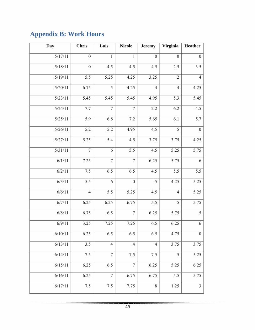
Appendix B: Work Hours
Day Chris Luis Nicole Jeremy Virginia Heather
5/17/11 0 1 1 0 0 0
5/18/11 0 4.5 4.5 4.5 2.5 3.5
5/19/11 5.5 5.25 4.25 3.25 2 4
5/20/11 6.75 5 4.25 4 4 4.25
5/23/11 5.45 5.45 5.45 4.95 5.3 5.45
5/24/11 7.7 7 7 2.2 6.2 4.5
5/25/11 5.9 6.8 7.2 5.65 6.1 5.7
5/26/11 5.2 5.2 4.95 4.5 5 0
5/27/11 5.25 5.4 4.5 3.75 3.75 4.25
5/31/11 7 6 5.5 4.5 5.25 5.75
6/1/11 7.25 7 7 6.25 5.75 6
6/2/11 7.5 6.5 6.5 4.5 5.5 5.5
6/3/11 5.5 6 0 5 4.25 5.25
6/6/11 4 5.5 5.25 4.5 4 5.25
6/7/11 6.25 6.25 6.75 5.5 5 5.75
6/8/11 6.75 6.5 7 6.25 5.75 5
6/9/11 3.25 7.25 7.25 6.5 6.25 6
6/10/11 6.25 6.5 6.5 6.5 4.75 0
6/13/11 3.5 4 4 4 3.75 3.75
6/14/11 7.5 7 7.5 7.5 5 5.25
6/15/11 6.25 6.5 7 6.25 5.25 6.25
6/16/11 6.25 7 6.75 6.75 5.5 5.75
6/17/11 7.5 7.5 7.75 8 1.25 3
50
6/19/11 3 5 5 0 0 0
6/20/11 5.5 6 5.75 7.5 0 5.25
6/21/11 7 7 7 7.25 0 3.25
6/22/11 1 6.75 6.75 6.25 0 2.5
6/23/11 3.25 6.25 5.75 7.25 0 4.75
6/24/11 4 7.5 7.5 7.25 2.25 6.25
Total Hours 150.25 173.6 165.6 150.3 104.35 122.15
Total Team Hours 866.25
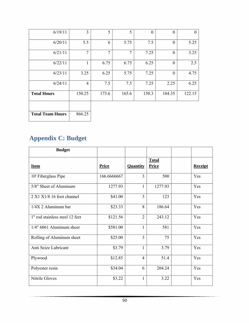
Appendix C: Budget
Budget
Item Price QuantityTotal Price Receipt
10' Fiberglass Pipe 166.6666667 3 500 Yes
5/8" Sheet of Aluminum 1277.93 1 1277.93 Yes
2 X1 X1/8 16 foot channel $41.00 3 123 Yes
1/4X 2 Aluminum bar $23.33 8 186.64 Yes
1'' rod stainless steel 12 feet $121.56 2 243.12 Yes
1/4" 6061 Aluminum sheet $581.00 1 581 Yes
Rolling of Aluminum sheet $25.00 3 75 Yes
Anti Seize Lubricant $3.79 1 3.79 Yes
Plywood $12.85 4 51.4 Yes
Polyester resin $34.04 6 204.24 Yes
Nitrile Gloves $3.22 1 3.22 Yes

51
Hardener Resin Polyester $5.20 1 5.2 Yes
Trim Cups for Resin $1.99 2 3.98 Yes
Paint brush Set $9.97 6 59.82 Yes
Buckets for Resin $3.16 1 3.16 Yes
Nitrile Gloves $2.48 1 2.48 Yes
Fleece for Ducks $13.97 4 55.88 Yes
Staples for Staple Gun $2.69 1 2.69 Yes
8" Stainless Bolts $5.18 9 46.62 Yes
Nylon Lock Nuts $0.29 41 11.89 Yes
Stainless Flat Washer $0.20 82 16.4 Yes
Locking Washer $0.21 41 8.61 Yes
3" Stainless Bolts $1.34 32 42.88 Yes
Bearings Mounted $8.54 4 34.16 Yes
Rolling of Aluminum sheet $25.00 1 25 Yes
Acetone $15.47 1 15.47 Yes
Gasoline $40.02 1 40.02 Yes
Hardener Resin Polyester $5.20 3 15.6 Yes
Paint Roller $2.14 3 6.42 Yes
Garage floor paint $53.43 1 53.43 Yes
6 Pack Paint Rollers $5.03 1 5.03 Yes
Boweye Stainless Steel $7.12 2 14.24 Yes
Switch for Bilge Pump $33.99 1 33.99 Yes
T/Hull - Marlon Insert $12.22 1 12.22 Yes
Clear PVC Hose 3/4" $1.02 3 3.06 Yes
3M Heat Shrink Butt Connectors $4.45 1 4.45 Yes

52
5200 Marine Adhesive $11.97 8 95.76 Yes
Paint Tray $2.98 1 2.98 Yes
Paint for Ducks $27.44 2 54.88 Yes
Electrical Wire $4.69 1 4.69 Yes
Wire connectors $3.99 1 3.99 Yes
7.5" zip ties $1.99 1 1.99 Yes
14" zip ties $1.99 1 1.99 Yes
3M Spray Adhesive 45 $5.77 5 28.85 Yes
Nylon Lock Nuts $0.70 7 4.9 Yes
Locking Washer $0.20 1 0.2 Yes
2.5" Threaded SS Bolts $1.59 2 3.18 Yes
Solar Lights $4.88 2 9.76 Yes
2" Paintbrushes $1.15 5 5.75 Yes
Bow Light Red/Green $15.94 1 15.94 Yes
Artist Brush Assortment $2.97 1 2.97 Yes
Teal paint Samples $2.94 2 5.88 Yes
Marine Grease $9.17 1 9.17 Yes
Shackles Large $6.44 4 25.76 Yes
Shackles Small $4.94 4 19.76 Yes
Total Spent 4070.44
Total Left in Budget 429.56
53
Appendix D: Cruise Report
Marine Field Projects 2011
Final Cruise Report
Team GECCO
Team Members:
Chris Ellert
Heather Weitzner
Jeremy Sirois
Luis Maristany
Nicole Waters
Virginia Tiede
Team Advisor:
Dr. Stephen Wood

54
Table of Contents
1.0 Introduction.………………………………………………………………………………………………………………………4 2.0 Methods.…………………………………………………………………………………………………………………………..5
2.1 Before Deployment………………………………………………………………………………………………5 2.2 Deployment Plans…………………………………………………………………………………………………5 2.3 Data Collection……………………………………………………………………………………………………..7 2.4 Mooring System……………………………………………………………………………………………………7 2.5 Retrieval……………………………………………………………………………………………………………….9 2.6 Data Collection……………………………………………………………………………………………………..9 3.0 Results….…………………………………………………………………………………………………………………………..10 3.1 Oceanographic Results………………………………………………………………………………………….10 3.2 Observational Analysis………………………………………………………………………………………….11 3.21 Visual Observations……………………………………………………………………………….11 3.22 Theoretical Calculations…………………………………………………………………………12 4.0 Implications, Conclusion, and Discussion…………………………………………………………………………..13 4.1 Possible Foreseen Implications…………………………………………………………………………….13 4.2 Discussion…………………………………………………………………………………………………………….14 4.3 Conclusion……………………………………………………………………………………………………………14 5.0 Appendices………………………………………………………………………………………………………………………..15
5.1 Course Mapping and Outlining……………………………………………………………………………..15 5.2 Daily Plan and Logging………………………………………………………………………………………….15 5.3 Assigned Duties and Tasks.…………………………………………………………………………………..18 5.4 Night watch….…………….………………………………………………………………………………………..19 5.5 List of Equipment……………………………………….…………………………………………………………19
5.6 Downtime Activities………………………………………………………………………………………………19 5.7 Allergies………………………………………………………………………………………………………………..20 5.8 Diving Material……………………………………………………………………………………………………..20 5.9 Diving Medical History Form…………………………………………………………………………………21 5.10 Florida Tech Project Approval Form…………………………………………………………………….23 5.11 Application for Florida Tech Dive Card Approval………………………………………………….24 5.12 Florida Tech Emergency Information Card…………………………………………………………..26 5.13 Florida Tech Pre-Dive Checklist - Lead Diver……………………………………………..…………27 5.14 Florida Tech Diving Log………………………………………………………………………………………..29 5.15 NOAA Data June 26th to 29th………………………………………………………………………………..31 5.16 Power Calculations………………………………………………………………………………………………35 5.17 Mooring Calculations……………………………………………………………………………………………36

55
List of Figures Figure 1: Trailered System……………………………………………………………………………………………………..5 Figure 2: Tide Chart for June 26th 2011..…………………………………………………………………………………6 Figure 3: Tide Chart for June 29th 2011.………………………………………………………………………………….6 Figure 4: Deployment………………………..…………………………………………………………………………………..7 Figure 5: Mooring System Side View………………………………………………………………………………………8 Figure 6: Mooring System Top View……………………………………………………………………………………….8 Figure 7: Using the A-frame……………………………………………………………………………………………………9 Figure 8: Deployment Location……………………………………………………………………………………………….15
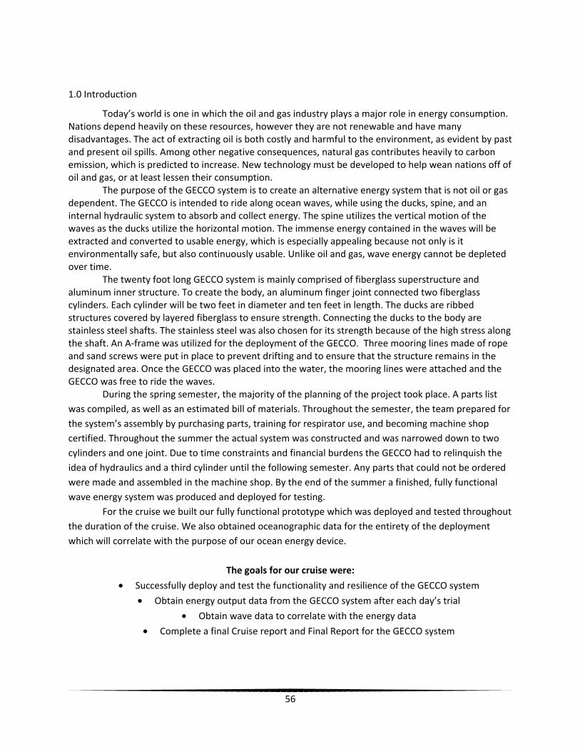
56
1.0 Introduction
Today’s world is one in which the oil and gas industry plays a major role in energy consumption. Nations depend heavily on these resources, however they are not renewable and have many disadvantages. The act of extracting oil is both costly and harmful to the environment, as evident by past and present oil spills. Among other negative consequences, natural gas contributes heavily to carbon emission, which is predicted to increase. New technology must be developed to help wean nations off of oil and gas, or at least lessen their consumption. The purpose of the GECCO system is to create an alternative energy system that is not oil or gas dependent. The GECCO is intended to ride along ocean waves, while using the ducks, spine, and an internal hydraulic system to absorb and collect energy. The spine utilizes the vertical motion of the waves as the ducks utilize the horizontal motion. The immense energy contained in the waves will be extracted and converted to usable energy, which is especially appealing because not only is it environmentally safe, but also continuously usable. Unlike oil and gas, wave energy cannot be depleted over time. The twenty foot long GECCO system is mainly comprised of fiberglass superstructure and aluminum inner structure. To create the body, an aluminum finger joint connected two fiberglass cylinders. Each cylinder will be two feet in diameter and ten feet in length. The ducks are ribbed structures covered by layered fiberglass to ensure strength. Connecting the ducks to the body are stainless steel shafts. The stainless steel was also chosen for its strength because of the high stress along the shaft. An A-frame was utilized for the deployment of the GECCO. Three mooring lines made of rope and sand screws were put in place to prevent drifting and to ensure that the structure remains in the designated area. Once the GECCO was placed into the water, the mooring lines were attached and the GECCO was free to ride the waves. During the spring semester, the majority of the planning of the project took place. A parts list was compiled, as well as an estimated bill of materials. Throughout the semester, the team prepared for the system’s assembly by purchasing parts, training for respirator use, and becoming machine shop certified. Throughout the summer the actual system was constructed and was narrowed down to two cylinders and one joint. Due to time constraints and financial burdens the GECCO had to relinquish the idea of hydraulics and a third cylinder until the following semester. Any parts that could not be ordered were made and assembled in the machine shop. By the end of the summer a finished, fully functional wave energy system was produced and deployed for testing. For the cruise we built our fully functional prototype which was deployed and tested throughout the duration of the cruise. We also obtained oceanographic data for the entirety of the deployment which will correlate with the purpose of our ocean energy device.
The goals for our cruise were:
• Successfully deploy and test the functionality and resilience of the GECCO system
• Obtain energy output data from the GECCO system after each day’s trial
• Obtain wave data to correlate with the energy data
• Complete a final Cruise report and Final Report for the GECCO system

57
2.0 Methods
2.1 Before Deployment
Before Deploying the GECCO system many precautions and practice runs were made to ensure accuracy and efficiency during the MFP cruise. Screw Testing
• Divers practiced screwing in the sand screws in a sandy bottom location. They will test once with the water clear, once with it murky, and once with their eyes closed and no visibility.
Assembly Trials
• One week before deployment the GECCO team performed “pit crew” style trials on assembling and disassembling the system. It allowed for team members to be assigned to specific parts of the GECCO system on the deployment day and retrieval day.
2.2 Deployment Plan
For the successful collection of data the system was deployed and the following plan was executed for transportation, deployment and retrieval.
Transportation to Deployment Site:
Use of Trailers • Trailers were used instead of a flat bed truck to save on cost; the same criteria for
transportation apply. • GECCO was broken down into two sections and transported on two separate trailers to
make it easier to load onto the RV Thunderforce
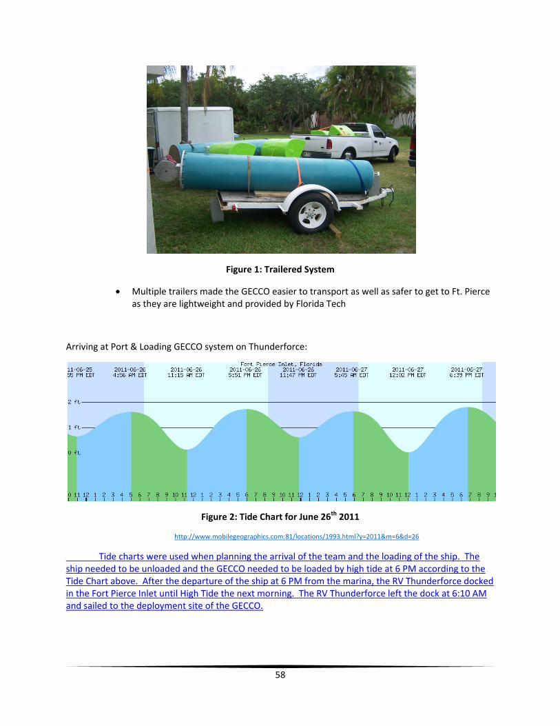
58
Figure 1: Trailered System
• Multiple trailers made the GECCO easier to transport as well as safer to get to Ft. Pierce as they are lightweight and provided by Florida Tech
Arriving at Port & Loading GECCO system on Thunderforce:
Figure 2: Tide Chart for June 26th 2011
http://www.mobilegeographics.com:81/locations/1993.html?y=2011&m=6&d=26
Tide charts were used when planning the arrival of the team and the loading of the ship. The ship needed to be unloaded and the GECCO needed to be loaded by high tide at 6 PM according to the Tide Chart above. After the departure of the ship at 6 PM from the marina, the RV Thunderforce docked in the Fort Pierce Inlet until High Tide the next morning. The RV Thunderforce left the dock at 6:10 AM and sailed to the deployment site of the GECCO.

59
Figure 3: Tide Chart for June 29th 2011
http://www.mobilegeographics.com:81/locations/1993.html?y=2011&m=6&d=28
When returning the tide charts were used to return back into Fort Pierce Inlet. We left the GECCO deployment site at 5:00PM and arrived at 5:20PM for dinner. At 6:45PM the RV Thunderforce returned to the marina where it was docked overnight until the next morning for offloading of the GECCO.
2.3 Deployment off of RV-Thunderforce:
1. Surveyed bottom of ocean at specified deployment site 2. Sent dingy out to drop anchors at four specified points for the moorings and buoy 3. Sent divers in to install moorings and check for accurate instillation 4. Attached the three lines to the center mooring buoy 5. Measure and confirm wave height is within safe parameters for deployment 6. Deploy GECCO system using A-frame and two slings and two hook straps
Figure 4: Deployment
7. Attached three mooring lines to the GECCO 8. Check functionality of system and waterproofing 9. Began data collection of pictures and video and oceanographic data
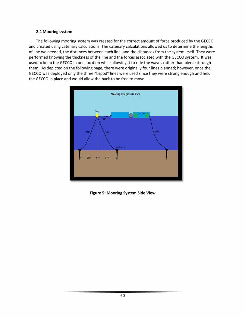
60
2.4 Mooring system
The following mooring system was created for the correct amount of force produced by the GECCO and created using catenary calculations. The catenary calculations allowed us to determine the lengths of line we needed, the distances between each line, and the distances from the system itself. They were performed knowing the thickness of the line and the forces associated with the GECCO system. It was used to keep the GECCO in one location while allowing it to ride the waves rather than pierce through them. As depicted on the following page, there were originally four lines planned; however, once the GECCO was deployed only the three “tripod” lines were used since they were strong enough and held the GECCO in place and would allow the back to be free to move.
Figure 5: Mooring System Side View
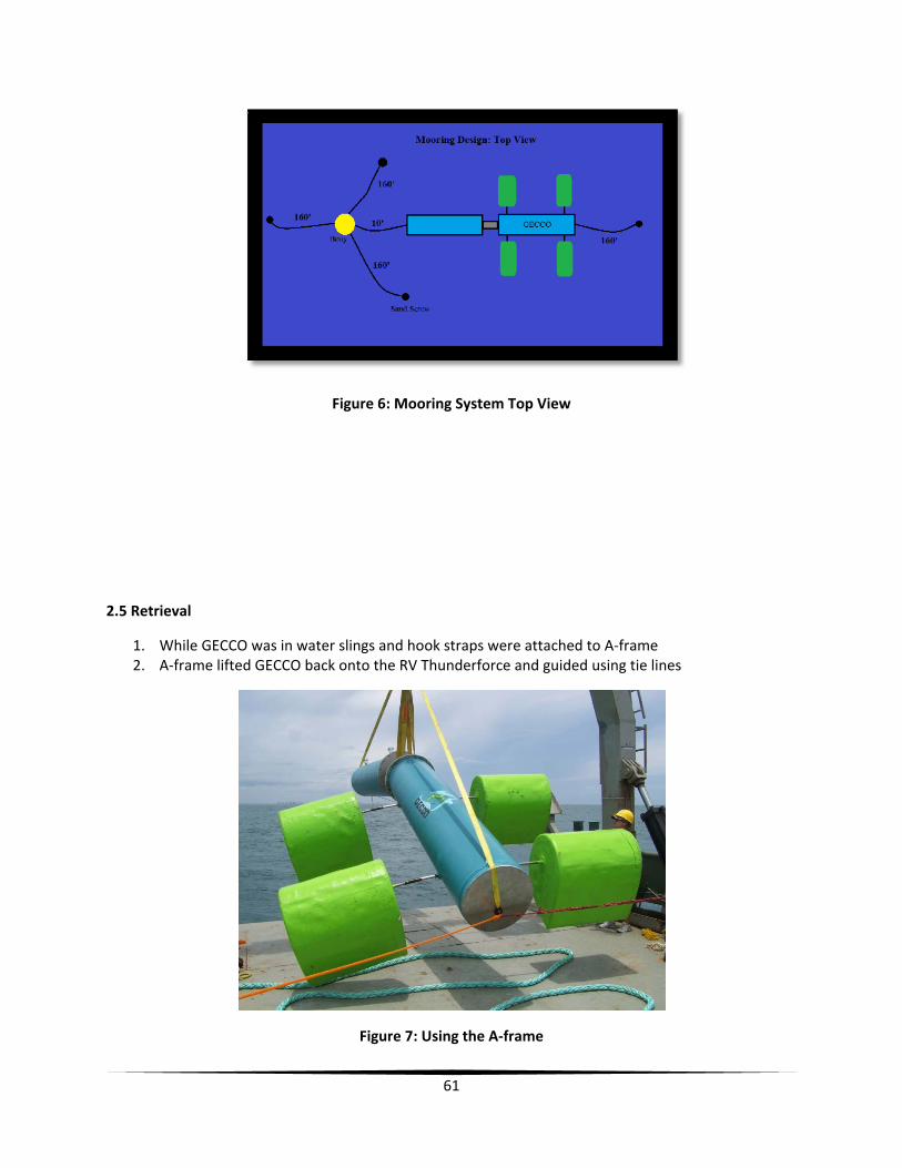
61
Figure 6: Mooring System Top View
2.5 Retrieval
1. While GECCO was in water slings and hook straps were attached to A-frame 2. A-frame lifted GECCO back onto the RV Thunderforce and guided using tie lines
Figure 7: Using the A-frame

62
3. Check for functionality and intact system 4. Rinsed down the system and hardware to prevent from further rusting 5. Stopped oceanographic data collection
Implications:
1. Do not swim near the device while in operation 2. Remain on skiff while removing pins 3. Keep distance from the ducks to avoid breaking them 4. Avoid going into the water when on skiff to avoid propeller 5. Be careful to keep bodily parts away from pinching parts of joints 6. Be aware of mooring lines to avoid entanglement 7. May not deploy due to weather
2.6 Data Collection
To successfully complete the operation of the GECCO system we obtained oceanographic and energy data that correlates with the progress of our project.
Oceanographic Data
1. Initial visual estimate –wave height, period, wave length, water depth 2. Use NOAA buoy data to check accuracy of wave conditions
Energy Data
1. By visual analysis, calculated the angle of the joint 2. Using the angle of the joint ********TBD
Implications:
1. Retrieve inconclusive data due to improper functionality of system 2. Collect no data due to total failure of system due to waterproofing failure 3. NOAA buoy collects false information
3.0 Results
The results of the Marine Field Project Cruise include oceanographic data concluded from the NOAA buoy and our observational analysis of the GECCO itself portrayed in the team member’s personal accounts, videos, and pictures from which calculations were performed.
3.1 Oceanographic Results
The following data was collected from the Ft. Pierce NOAA buoy and used to find an average wind speed, wave height, wave direction, and average period. The following recordings were taken during the entire duration of deployment of the GECCO.

63
Time Wind Speed (mph)
Wave Height (ft)
Wave Direction (deg)
Wave Period (s)
6/27/2011 3:16 PM 12 1 ENE 74 4.1 3:46 PM 12 1.3 ESE 115 3.5 4:16 PM 12 1.3 ESE 109 5 5:16 PM 11 1.6 ESE 114 3.4 5:46 PM 12 1.6 ESE 111 3.4 6:16 PM 12 1.6 ESE 114 3.5 6:46 PM 10 1.6 ESE 111 3.5 7:16 PM 9 1.6 E 101 3.6 7:46 PM 8 1.6 ESE 111 3.6 8:16 PM 8 1.6 ESE 108 3.7 8:46 PM 9 1.6 ESE 114 3.6 9:16 PM 6 1.3 ESE 107 3.5 9:46 PM 5 1.3 E 100 3.6
10:16 PM 5 1.3 E 92 3.7 10:46 PM 3 1.3 E 92 3.6 11:16 PM 2 1.3 E 90 3.6 11:46 PM 0 1.3 E 91 3.6
6/28/2011 12:16 AM 3 1.3 E 90 3.7 12:46 AM 0 1.3 E 98 3.7
1:16 AM 5 1.3 E 94 3.7 1:46 AM 5 1.3 E 98 3.9 2:16 AM 6 1.3 E 101 3.8 2:44 AM 7 1.3 E 91 3.6 3:16 AM 6 1.3 ENE 70 3.4 3:46 AM 5 1.3 ESE 104 3.5 4:16 AM 0 1.3 ESE 105 3 4:45 AM 5 1.3 ESE 102 3.3 5:16 AM 13 1.3 ESE 205 3.4 5:45 AM 10 1.3 ESE 111 3.3 6:15 AM 9 1.3 ESE 111 3 6:45 AM 19 1.3 ESE 105 3.2 7:15 AM 6 1.3 ESE 105 4 7:46 AM 5 1.3 ESE 121 3.2 8:16 AM 4 1.6 SE 132 3.2 8:46 AM 4 1.6 SE 125 3.2 9:16 AM 3 1.6 SE 126 3.3 9:46 AM 0 1.6 SE 128 3.4

64
10:16 AM 0 1.6 ESE 119 3.3 10:46 AM 0 1.6 ESE 116 3.4 11:16 AM 0 1.6 ESE 116 3.5 11:46 AM 0 1.6 ESE 121 3.5 12:16 PM 5 1.6 ESE 123 3.6 12:46 PM 8 1.6 ESE 123 3.6
3.2 Observational Analysis
During the duration of the GECCO’s deployment we took many videos, photos, and personal accounts of the functionality of the GECCO. Our visual observations that were recorded and theoretical calculations performed serve as the biggest form of data analysis for the GECCO itself
3.21 Visual Observations
Since there was not a hydraulic system during deployment of the GECCO system, most of our data obtained was through observation. As the system initially went into the ocean the main priority was to make sure all of the systems, such as the joint and the ducks, were functioning properly and no major faults were present. More importantly, making sure the system was not rapidly taking on water and sinking was crucial and this was done by watching the water line of the GECCO and making sure it wasn’t changing and also by observing whether the bilge pump inside the main body section was not pumping out water too frequently. Once it was clear that the system was functioning properly and no imminent danger to the system was evident we could then record other observations such as oceanographic data. Wave data such as average wave height, direction, and period were recorded on the hour and video was recorded and later analyzed to determine the speed at which the ducks and the joint were oscillating. This will further allow us to record theoretical data to be discussed in the next section.
The most interesting visual observation recorded was what happened to the GECCO when the waves and current were facing certain directions. When the current and waves were headed in the same direction, facing head on to the end caps of the GECCO, the joint undulated much more rapidly and to larger angles while the ducks rotated at a slower speed and at smaller angles. When the current and waves were perpendicular to one another the joint was much less effective, moving at smaller angles; however, the ducks moved much more rapidly and rotated at greater angles.
3.22 Theoretical Calculations
By recording the speed of the ducks and the range of motion of the joint, a theoretical value for energy production can be obtained for the wave height recorded during deployment; this value can provide a
65
close approximation to what energy the GECCO is extracting from the sea and converting to electricity. The amount of energy produced by the GECCO is dependent upon several factors within the hydraulics system. Pipe diameter, type of hydraulic fluid, and pump size are a few variables that will alter the output results, however the effect of these components will be better understood when the hydraulic system is in place. For this system, it is assumed that there are minor losses due to friction, bends, etc. In addition, because the system is on a horizontal plane, there are no changes to the head.
In order to determine the mechanical energy created by the GECCO, the amount of torque applied to the system must be calculated and the characteristics of various parts within the system, such as the pump, must be evaluated. To do so, the force on the duck from the wave must be calculated. It was assumed that this force is continuous instead of sinusoidal, as a wave actually is.
Upon completion of the GECCO, various aspects of the system were calculated and analyzed. Based on visual observations during testing the proper orientation of the system was determined and the average power output was calculated. Initially the GECCO was placed in the water in a way that allowed the joint to move freely, however the ducks did not rotate to their full potential. When the system was revolved 180 degrees, the ducks rotated perfectly but the joint did not undulate as well as initially. To allow both components to perform efficiently so the maximum wave energy is extracted, the system must be angled between the two tested positions.
After the cruise was completed, videos of the testing were analyzed to determine the rotational velocity of the ducks and the translational velocity of the joint. From this data the revolutions per minute could be calculated which would then yield the flow rate and pressure created by the pump and hydraulic system within the GECCO. These values, paired with the torque applied to the ducks, provide the final power output of the system: 7.48 GWh/year. “The average household in the United States uses about 8,900 kilowatt-hours of electricity each year” ("Electrical Energy", The New Book of Popular Science), which means the system could power nearly one thousand homes a year through the ducks alone. However, the assumptions made do not include frictional losses, bend and elbow losses of the pipes, turbulence, or other realistic sources of energy depletion. The calculations are based on summer conditions, during which wave heights are minimal. Given greater wave heights of the winter months, the power output of the system would also be much greater. In addition, the calculations do not include the power extracted by the joint, which is a major contributor to energy collection. Using other means of calculations, a minimum duck power output of 346 kWh/year was determined. Neither of these values is realistic and do not represent the actual power output of the system. There are too many variables and complexities to obtain an accurate result.
4.0 Implications, Discussion, and Conclusion
4.1 Possible Foreseen Implications
The following listed are implications that were foreseen before the cruise; however, were avoided during the deployment and the testing of the GECCO.
• Total system failure due to: o Major Structural Defect
66
o Waterproofing Failure o Total Mechanical Failure o Mooring Failure o Poor Weather Conditions
• Inconclusive Data o Calm weather conditions – No waves means no energy o Rough Weather Conditions – Device cannot be deployed o Instrumentation Failure – Cannot achieve weather data o Poor calibration of instrumentation
4.2 Discussion
The very successful deployment of the GECCO system proves the functionality and effectiveness of the design. The system showed a smooth operation throughout the 24 hours that it was deployed. The joint worked well without any binding even in cross current conditions. The most delicate part of the system, the ducks, also proved to be sufficiently stable and resilient enough to survive the deployment off of the ship and the testing at sea. The Ducks also showed very good mobility with little effort and even under very low chop conditions they were moving energetically. The body of the system proved strong enough for deployment conditions and there were very few leaks and only a small amount of water remained inside the sections. This leaking probably occurred through small seams in the shafts for the ducks and the seam where the joint is connected. Leaking on such a system is inevitable and instead of designing for a completely watertight system buoyancy was added to keep the system afloat while being completely flooded. The most leaking took place inside the ducks and these had a significant amount of water in them; although it did not appear to affect the function of the ducks. High amounts of water in the ducks eventually change their buoyancy, which is crucial to the function of the design. Since deployment of the GECCO system is now complete, the prototype will continue to change as more modifications are made. The priority now is to install a functioning hydraulic system that can produce electricity and obtain some real world data on the performance of the system. The next step is to build a new joint and attach a third body section to the GECCO and complete the design. Once the system is fully built and tested, a large-scale system can be built and tested in more extreme sea conditions where more energy can be extracted and the system can function to its full potential. Before any modifications can be made to the system more funding must be procured to purchase the proper parts and materials to make the system fully functional.
4.3 Conclusion Finally the cruise in its entirety achieved its goal of successfully loading, deploying, retrieving, and unloading of the GECCO system. All aspects carried through with only minor issues if any at all. The success of the testing proves that the GECCO is based on an effective design that produced a useful prototype. More testing needs to be done with the system now that it is clearly durable and functional enough to survive the rigors of deployment within the marine environment. The next step involves solving the minor issues that occurred, such as the minor leaks of the Ducks and the body, and also

67
installing the hydraulics in the system, which will allow for concrete data and begin the conversion of wave energy to electrical energy. Once the hydraulics are installed and tested the true effectiveness of the GECCO system can be determined. For now the prototype shows potential for being an effective energy system and already has exceeded expectations.
5.0 Appendixes
5.1 Course Mapping and Outlining
Figure 8: Deployment Location
GECCO Deployment Coordinates
• 27° 26’ 0.445” N 80° 13’ 0.565” W
• Water depth: 24 feet
RV Thunderforce Location to observe GECCO
• 27° 26’ 0.428” N 80° 13’ 0.526” W
• Water depth: 30 feet
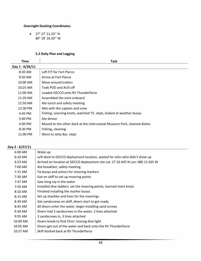
68
Overnight Docking Coordinates
• 27° 27’ 51.55’’ N 80° 18’ 26.20’’ W
5.2 Daily Plan and Logging
Time Task
Day 1 - 6/26/11
8:30 AM Left FIT for Fort Pierce
9:50 AM Arrive at Fort Pierce 10:00 AM Move around trailers
10:25 AM Took POD and AUV off 11:00 AM Loaded GECCO onto RV Thunderforce
11:20 AM Assembled the Joint onboard 11:50 AM Ate lunch and safety meeting
12:30 PM Met with the captain and crew 4:45 PM Fishing, Learning knots, watched TV, slept, looked at weather buoys
5:00 PM Ate dinner 6:00 PM Moved to the other dock at the intercoastal Museum Park, cleaned dishes
8:30 PM Fishing, cleaning 11:00 PM Went to Jetty Bar, slept
Day 2 - 6/27/11 6:00 AM Woke up 6:10 AM Left dock to GECCO deployment location, waited for John who didn't show up 6:53 AM Arrived on location at GECCO deployment site Lat: 27 26.445 N Lon: 080 13.565 W 7:00 AM Ate breakfast, safety meeting 7:15 AM Fix buoys and achors for mooring markers 7:30 AM Got on skiff to set up mooring points 7:47 AM Saw sting ray in the water 7:50 AM Installed dive ladders, set the mooring points, learned more knots
8:10 AM Finished installing the marker buoys
8:15 AM Set up shackles and lines for the moorings
8:30 AM Get sandscrews on skiff, divers start to get ready 8:45 AM All divers enter the water, begin installing sand screws 9:30 AM Divers had 2 sandscrews in the water, 2 lines attached 9:55 AM 3 sandscrews in, 3 lines attached
10:00 AM Divers break to find Chris' missing dive light 10:05 AM Divers get out of the water and back onto the RV Thunderforce 10:27 AM Skiff docked back at RV Thunderforce
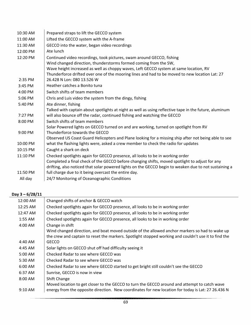
69
10:30 AM Prepared straps to lift the GECCO system 11:00 AM Lifted the GECCO system with the A-frame 11:30 AM GECCO into the water, began video recordings 12:00 PM Ate lunch
12:20 PM Continued video recordings, took pictures, swam around GECCO, fishing
2:35 PM
Wind changed direction, thunderstorms formed coming from the SW, Wave height increased as well as choppy waves, Left GECCO system at same location, RV Thunderforce drifted over one of the mooring lines and had to be moved to new location Lat: 27 26.428 N Lon: 080 13.526 W
3:45 PM Heather catches a Bonito tuna
4:00 PM Switch shifts of team members 5:06 PM Chris and Luis video the system from the dingy, fishing 5:40 PM Ate dinner, fishing
7:27 PM Talked with captain about spotlights at night as well as using reflective tape in the future, aluminum will also bounce off the radar, continued fishing and watching the GECCO
8:00 PM Switch shifts of team members
9:00 PM Solar Powered lights on GECCO turned on and are working, turned on spotlight from RV Thunderforce towards the GECCO
10:00 PM Observed US Coast Guard Helicopters and Plane looking for a missing ship after not being able to see what the flashing lights were, asked a crew member to check the radio for updates
10:15 PM Caught a shark on deck 11:10 PM Checked spotlights again for GECCO presence, all looks to be in working order
11:50 PM
Completed a final check of the GECCO before changing shifts, moved spotlight to adjust for any drifting, also noticed that solar powered lights on the GECCO begin to weaken due to not sustaining a full charge due to it being overcast the entire day.
All day 24/7 Monitoring of Oceanographic Conditions
Day 3 – 6/28/11 12:00 AM Changed shifts of anchor & GECCO watch 12:25 AM Checked spotlights again for GECCO presence, all looks to be in working order 12:47 AM Checked spotlights again for GECCO presence, all looks to be in working order 1:55 AM Checked spotlights again for GECCO presence, all looks to be in working order 4:00 AM Change in shift
4:40 AM
Wind changed direction, and boat moved outside of the allowed anchor markers so had to wake up the crew and captain to reset the markers. Spotlight stopped working and couldn’t use it to find the GECCO
4:45 AM Solar lights on GECCO shut off had difficulty seeing it 5:00 AM Checked Radar to see where GECCO was 5:30 AM Checked Radar to see where GECCO was 6:00 AM Checked Radar to see where GECCO started to get bright still couldn’t see the GECCO 6:37 AM Sunrise, GECCO is now in view 8:00 AM Shift Change
9:10 AM Moved location to get closer to the GECCO to turn the GECCO around and attempt to catch wave energy from the opposite direction. New coordinates for new location for today is Lat: 27 26.436 N

70
Lon: 080 13.539 W Depth: 27 feet
9:15 AM
Rotated the GECCO to have the duck section facing first into the current, current and swell are coming from opposite directions and the ducks are moving more efficiently since the swell is overpowering the current. Joint is being hit by water perpendicular so the joint is moving less than previous recordings. Recorded video and pictures of ducks moving more efficiently.
10:30 AM Fixed the motor on the dingy that was taking in/not getting enough fuel 11:00 AM Went swimming to find missing pin that was dropped into the water a day earlier 12:00 PM Shifts change, Sheriff boat docks next to GECCO 12:45 PM Begin recovery of GECCO 1:30 PM Retrieval of GECCO complete
1:35 PM Divers start getting ready to retrieve sand screws and buoys with assistance of dingy 1:45 PM Divers get into the water to retrieve the screws 1:55 PM First sandscrew up 2:03 PM First anchor up
2:04 PM Second sandscrew up 2:10 PM Second anchor and third sandscrew up 2:12 PM Mooring buoy up 2:13 PM Third anchor up
2:15 PM All divers up and out of the water onto the RV Thunderforce 2:17 PM Finished collecting all buoys and lines and dingy returns to RV Thunderforce
2:20 PM Retrieved lines, screws, and buoys from the dingy and start hosing down hardware and cleaning the deck
2:25 PM Retrieved the dingy back onto RV Thunderforce
2:35 PM Finished tying up all lines, buoys, screws and dingy as well as cleaning the deck and arranging for tomorrows’ offloading of the GECCO and supplies
5:00 PM Returned to the overnight docking area for dinner 6:00 PM Ate dinner 6:45 PM Returned to deployment site at the marina for offloading the next morning 8:00 PM Went to bar
10:30 PM Returned back to RV Thunderforce and went to sleep
Day 4 - 6/29/11 8:00 AM Woke up and got all of the supplies ready to be offloaded off the RV Thunderforce 8:30 AM Ate breakfast
9:00 AM Unloaded all personal belongings into the trucks and vans to be returned to Florida Tech
9:30 AM Started to offload the GECCO onto trailers with the crane piece by piece after disassembling the joint
10:15 AM Offloaded the dingy and deflated it to be placed into the back of a truck
10:30 AM Strapped down all of the components of the GECCO onto the trailers for the return to Florida Tech
11:00 AM Returned to Florida Tech and offloaded supplies out of the trailers
5.3 Assigned Duties & Tasks
Tasks Day 1 - 6/26/11
Day 2 - 6/27/11
Day 3 - 6/28/11
Day 4 - 6/29/11

71
Galley N,L,J N,L,J,C C, H C,H Deck L,N,C,J L,C,N,H J,N,L All Nightwatch None All None None
Key
C=Chris H=Heather L=Luis J=Jeremy N=Nicole
5.4 Nightwatch
Day 4:00PM – 8:00PM 8:00PM – 12:00AM 12:00AM – 4:00AM 4:00AM – 8:00AM 6/26/11 None - Docked None - Docked None - Docked None - Docked 6/27/11 Jeremy, Nicole Nicole, Luis Heather, Chris Jeremy, Aaron 6/28/11 None - Docked None - Docked None - Docked None - Docked
5.5 List of Equipment
System Equipment Extra Equipment Personal Equipment
GECCO System Fishing Equipment Pillow Tools Snorkeling Equipment Blankets Computers Board Games Clothes ADCP Card Games Toiletries Silicone Kayak Feminine Products Ducktape Live Bait Seasick Medicine Extra Pins Cast Net Swimsuits Hydraulic Fluid Inflatable Equipment Shoes Rope Sunscreen Dive Equipment Towels Tanks Hats Dingy Aloe Motor for Dingy Money Sand-screws Prescription Meds Chain Nuts and Bolts
5.6 Downtime Activities

72
Downtime Activities Fishing Tanning Snorkeling Card Games TV Inputting Data Phone Calls Eating Sleeping Swimming Learning Knots
5.7 Allergies
Name Medicine Allergy Food Allergy Medical Conditions Chris Ellert Penicillin None None Luis Maristany None None None Nicole Waters Hepatitis B Vaccine Cucumbers, Melons, Zucchini Epilepsy Jeremy Sirois Sulfa(s) Shellfish None Heather Weitzner None None None
5.8 Diving Logs
The following log is for the screw instillation of the mooring system of the GECCO system. All of the following divers are AAUS certified and this was the first of a total two dives for the GECCO project.
6/27/2011 Aaron Macy Dr. Wood
Chris Ellert
Air In 3000 p.s.i. 3000 p.s.i 2850 p.s.i Air Out 1500 p.s.i 1500 p.s.i 1210 p.s.i Time In Water 8:45 AM 8:45 AM 8:45 AMVideo Dive Time Down 9:02 AM 9:02 AM 9:02 AMTime Up 9:06 AM 9:06 AM 9:06 AMScrew 1 Time Down 9:13 AM 9:13 AM 9:13 AMTime Up 9:19 AM 9:19 AM 9:19 AMScrew 2 Time Down 9:22 AM 9:22 AM 9:22 AMTime Up 9:25 AM 9:25 AM 9:24 AMScrew 3 Time Down 9:42 AM 9:42 AM 9:42 AMTime Up 9:47 AM 9:47 AM 9:47 AMInspection dive
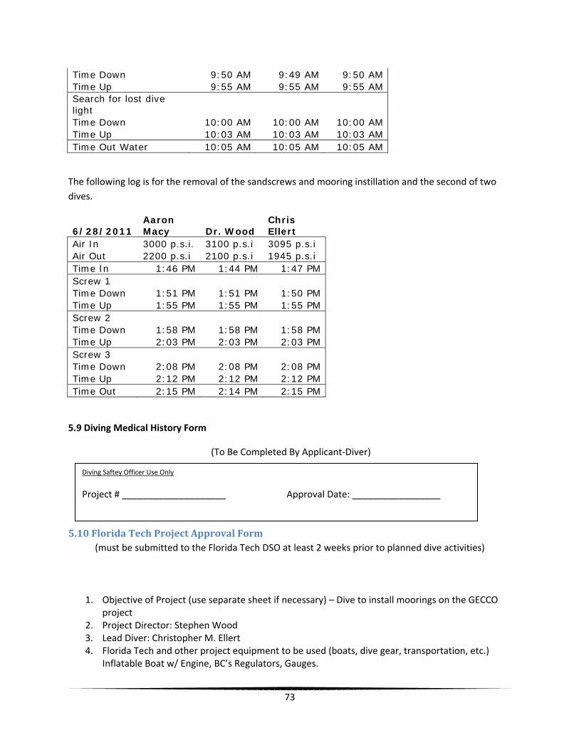
73
Time Down 9:50 AM 9:49 AM 9:50 AMTime Up 9:55 AM 9:55 AM 9:55 AMSearch for lost dive light Time Down 10:00 AM 10:00 AM 10:00 AMTime Up 10:03 AM 10:03 AM 10:03 AMTime Out Water 10:05 AM 10:05 AM 10:05 AM
The following log is for the removal of the sandscrews and mooring instillation and the second of two dives.
6/28/2011 Aaron Macy Dr. Wood
Chris Ellert
Air In 3000 p.s.i. 3100 p.s.i 3095 p.s.i Air Out 2200 p.s.i 2100 p.s.i 1945 p.s.i Time In 1:46 PM 1:44 PM 1:47 PMScrew 1 Time Down 1:51 PM 1:51 PM 1:50 PMTime Up 1:55 PM 1:55 PM 1:55 PMScrew 2 Time Down 1:58 PM 1:58 PM 1:58 PMTime Up 2:03 PM 2:03 PM 2:03 PMScrew 3 Time Down 2:08 PM 2:08 PM 2:08 PMTime Up 2:12 PM 2:12 PM 2:12 PMTime Out 2:15 PM 2:14 PM 2:15 PM
5.9 Diving Medical History Form
(To Be Completed By Applicant-Diver)
5.10 Florida Tech Project Approval Form (must be submitted to the Florida Tech DSO at least 2 weeks prior to planned dive activities)
1. Objective of Project (use separate sheet if necessary) – Dive to install moorings on the GECCO project
2. Project Director: Stephen Wood 3. Lead Diver: Christopher M. Ellert 4. Florida Tech and other project equipment to be used (boats, dive gear, transportation, etc.)
Inflatable Boat w/ Engine, BC’s Regulators, Gauges.
Diving Saftey Officer Use Only
Project # ____________________ Approval Date: _________________

74
5. Special Diving Equipment: Sand Screws with tensioning bar
6. Dive Sites (use additional sheets if necessary) 1 Location _Ft Pierce_ Depth 22’ Day/Night Day
7. Date of first dive: 06/27/2011 8. Date of last dive: 06/29/2011 9. Estimated number of dives: 4 10. Names of All Divers (visiting divers must contact the FL Tech DSO at least 1 month in advance
regarding eligibility to dive under the auspices of the FL Tech Dive Program) Name Depth Rating Signature Christopher M. Ellert 60’ _______________ Aaron Macy 60’ _______________ Dr. Stephen Wood 120’ _______________
11. Name, location, phone number of hospital closest to dive site: St lucie Regional Medical Center 1800 SE Tiffany Avenue, Port St. Lucie, FL 34952
12. Name, location, phone number of nearest recompression chamber. Hyperbaric Medicine and Wound Care Management Center 407.303.1549. 601 East Rollins Orlando, FL 32803
13. List all available modes of transportation to be utilized (boats, autos, helicopter, etc) in the event of an emergency involving an injured diver. Boat, Helicopter, Auto (once ashore)
14. Signature of Faculty Coordinator: ______________________________________ Dept. _______________________ Phone __________________
5.11 Application for Florida Tech Dive Card Approval 5.12 Florida Tech Emergency Information Card
For Dive Safety Officer
5.13 : Florida Tech Pre-Dive Checklist – Lead Diver
Lead Diver
Project Approval Number __D011-015___
The Lead Diver is responsible for detailed planning of all underwater activity and to establish and discuss a rescue plan with all divers before any diving takes place. The responsibility of the Lead Diver requires preparation several days before the actual dive takes place. If a large group of divers is involved, a general meeting is recommended to discuss operational procedures at the dive site.

75
The Lead Diver must be at the dive site during the entire dive operation.
___√__ Do all divers have their Florida Tech Dive Certification Card?
List the names of the divers at the dive site:
Aaron Macy
Dr. Stephen Wood
Christopher Ellert
Mandatory on-site emergency equipment:
__√___ - First aid kit
__√___ - Emergency oxygen kit
__√___ - Dive flag(s)
___√__ - Emergency information cards
___√__ - Emergency information cards
Mandatory personal equipment:
___√__ - Mask, fins, snorkel
__√___ - Compressed air cylinder and valve
___√__ - Regulator (alternate air source is recommended)
__√___ - Buoyancy control device w/low pressure inflator
__√___ - Submersible pressure gauge
___√__ - Depth gauge
___√__ - Timing device
____√_ - Compass
___√__ - Adequate exposure protection
___√__ - Weight belt/weights w/quick release mechanism
___√__ - Slate
___√__ - Knife

76
___√__ - Night diving equipment (if applicable)
__√___ - Logbook
__√___ - PADI repetitive dive table
Review emergency procedures with divers
___√__ - Lost diver procedures
___√__ - Emergency numbers
___√__ - Emergency evacuation procedures
Review dive plan with all divers
___√__ - Formation of buddy teams
__√___ - Remind buddy teams that Lead Diver directs all in water-dive activities
___√__ - Entry and exit areas
___√__ - Discuss dive objectives
___√__ - Evaluate water and weather conditions and decide to “go” or “abort dive
___√__ - Discuss known and potential underwater hazards
___√__ - Discuss location of emergency oxygen equipment, first aid kit and diving emergency management procedures (appendix 7)
___√__ - Ensure proper display of dive flag(s)
___√__ - Roll call
___√__ - Debriefing after a dive (perform roll call again)
Remind divers
___√__ - Fill out their Florida Tech Dive Log Sheets ___√__ - Include Project Approval Number
List the time/depth limitations you imposed for dive(s):
Time: 40 min per dive
Depth 22 (bottom)

77
List any problems encountered:
None
As the Lead Diver for this project, I have discussed all the issues mentioned above and had at the dive site all the required mandatory equipment. I understand that failure to follow these guidelines, as well as the rules and regulations in the Florida Tech Dive Manual, may result in loss of diving privileges and cancelation of the Project Approval.
Signature of Lead Diver: ____________________________________________
5.14 Florida Tech Diving Log (Dive logs MUST be logged electronically at http://fit.diveaaus.com/ as soon as possible following
completion of dive activities. Failure to comply will result in suspension of diving privileges!)
Project Approval Number: ___________________ Date: ________________
Diver: Christopher M Ellert Dive Buddy: Aaron Macy, Dr. Stephen Wood
Lead Diver: Christopher M. Ellert
Location: Fort Pierce, Fl
Dive Start Time: 9:13 Dive End Time: 9:47 Total Bottom Time: _38 min
Maximum Depth: _22’_ Visibility: 20’
Type or breathing gas: Air
Surface Conditions:
calm
Underwater Conditions:
No current
Purpose of dive:
Insert sand screws For this dive, the PADI dive tables / a dive computer (circle one) were utilized (if a computer was utilized, please specify make and model): Comments (be sure to include details regarding any incidents or near incidents):
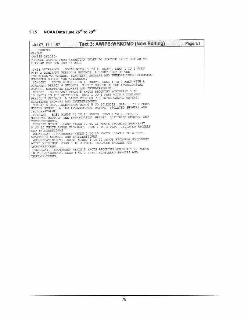
78
5.15 NOAA Data June 26th to 29th
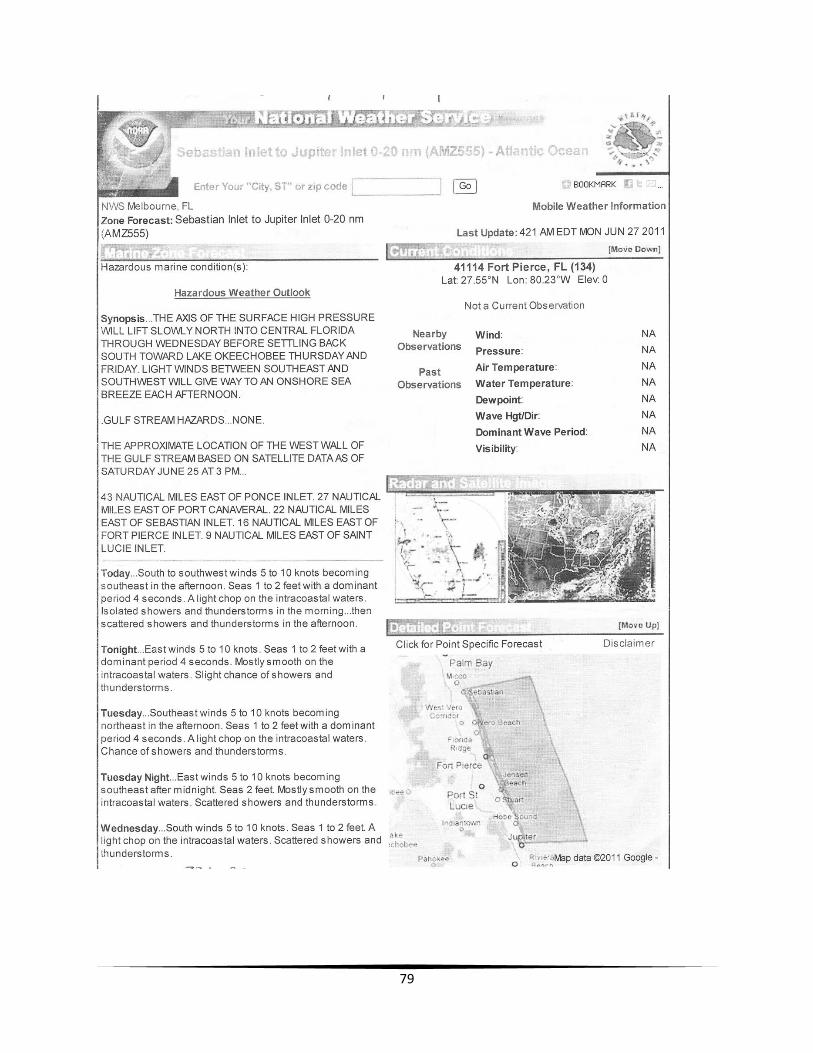
79
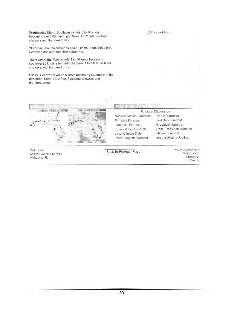
80

81
82

83
Appendix E: Calculations
Power Calculations

84

85
Mooring Calculations
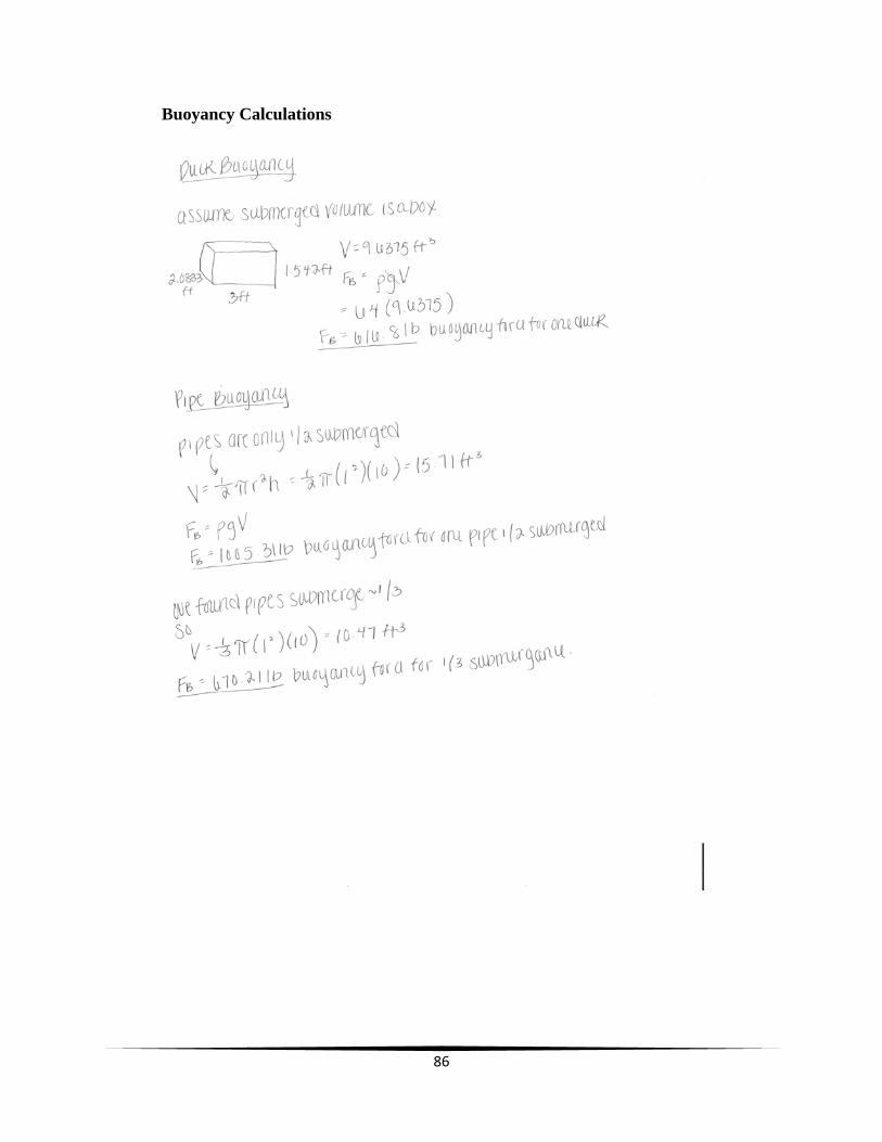
86
Buoyancy Calculations