Great Plains Turbo Seeder Operator s Manual
37
Great Plains Turbo Seeder Operator’s Manual
Transcript of Great Plains Turbo Seeder Operator s Manual

Great Plains Turbo Seeder Operator’s Manual

Gandy Company
815 Rice Lake St. Owatonna, MN 55060
Ph. (507) 451-5430 / Fax (507) 451-2857
Email: [email protected] / Web: www.gandy.net

Page 3 March 2016
OPERATION MANUAL
Table of Contents
TABLE OF CONTENTS
INTRODUCTION .........................................................................................................................5
LIMITED WARRANTY ................................................................................................................6
Orbit-Air / Zero-Max Identification ..........................................................................................7
Safety Information ..................................................................................................................8
SAFETY Decals ................................................................................................................9
Operator’s Manual Review ...............................................................................................9
Operator Safety ..............................................................................................................10
Safety Guidelines............................................................................................................10
Granular Chemical Safety............................................................................................... 11
Hydraulic Safety.............................................................................................................. 11
Transport Safety ............................................................................................................. 11
Storage Safety ................................................................................................................12
Orbit-Air Applicator ...............................................................................................................12
SET UP / OPERATION .............................................................................................................15
Control Unit Wiring Connections ..........................................................................................15
Hydraulics ............................................................................................................................17
Safe Operation .....................................................................................................................18
Control Unit ..........................................................................................................................19
Air Pressure Gauge..............................................................................................................20
Closure Slides ......................................................................................................................21
Calibration ............................................................................................................................22

Page 4 March 2016
OPERATION MANUAL
Table of Contents
Table of Contents (Continued)
MAINTENANCE ........................................................................................................................24
Routine Maintenance / Inspection .......................................................................................24
Hydraulic Blower.............................................................................................................24
Bearings..........................................................................................................................25
Lubrication ......................................................................................................................26
Safety..............................................................................................................................27
Clutches………………………………………………………………....................................27
Metering Wheels….………..............................................................................................29
Deflector Packages………..............................................................................................30
Post-Season Maintenance ...................................................................................................31
Pre-Season Maintenance.....................................................................................................32
Troubleshooting ...................................................................................................................33
INDEX........................................................................................................................................36

Page 5 March 2016
OPERATION MANUAL
Introduction
INTRODUCTION Our line of Orbit-Air applicators are designed to provide you with years of accurate and dependable performance when used for the purpose for which it was intended.
To make sure your applicator provides you with safe, efficient, and trouble-free operation, all personnel that operate this applicator must read and understand all the information included in this operator’s manual. It is the responsibility of the owner(s) of this equipment to ensure that the operator is fully instructed and understands the contents of this manual. If you have any questions about this manual or the equipment, contact your Gandy dealer, or the factory.
ALWAYS use original Gandy service parts as substitute parts could adversely affect equipment performance and warranty.
DEALER
Your authorized dealer is your primary source for parts and service. If you need assistance with the operation or maintenance of this applicator, contact your dealer, or the factory. For future reference, write the dealer’s name and phone number below:
Purchase Date:
Dealership:
Salesperson:
Address:
City/State/Zip:
Phone:
Email:
Web:

Page 6 March 2016
OPERATION MANUAL
Introduction
LIMITED WARRANTY
The Gandy Company warrants all material and workmanship on equipment delivered to be free of defects for a period of twelve months from date of original purchase. Products used on a commercial, rental, or leased basis are warranted for 90 days. Any part or parts thought to be defective within these warranty periods are to be returned through your servicing dealer or distributor to the Gandy Company’s plant. Distributor must receive authorization from Gandy Company to return items under warranty. An authorization number will be issued and must be clearly visible on all packages returned to the factory. If found defective by Gandy Company, replacement parts will be forwarded free of charge, prepaid. No service charge or expense on the equipment will be allowed unless such expense has been previously authorized in writing by the Gandy Company. Serial number and model of the unit involved is required by the Gandy Company on all warranty claims. Gandy Company policy is to improve products whenever it is practical to do so. It reserves the right to make changes or add improvements at any time without incurring any obligation to make such changes on products sold previously. This warranty does not apply to products altered by users after the point of manufacture.
This warranty against defects in material and workmanship is in lieu of all other warranties, expressed or implied, and there are no other warranties of any kind whatsoever including, but not limited to, any implied warranty of merchantability or fitness for any particular purpose. In no event shall the company be liable for any incidental or consequential damages, whether for breach of warranty, for breach or repudiation of any other term or condition hereof, or for negligence, on the basis of strict liability, or for any other reason.

Page 7 March 2016
OPERATION MANUAL
Introduction
ORBIT-AIR / ZERO-MAX IDENTIFICATION
Orbit-Air Serial Number / Model Number
The Company places a serial number and model number nameplate on the side panel of the Orbit-Air for easy identification. For parts, service, or technical information, always provide your dealer with the model and serial number.
Model:
Serial No.:
Zero-Max Serial Number / Model Number
The Company places a serial number and model number nameplate on the side of the Zero-Max rate controller for easy identification. In addition, a separate decal is placed next to it with information on where to obtain parts, service, or technical information. The Zero-Max cannot be serviced on location, but must be returned to the factory-authorized repair center.
Model:
Serial No.:
For Zero-Max parts and service, contact: Humphries Textile Parts, Inc. 3717 West Franklin Blvd. Gastonia, NC 28052
Phone: (704) 867-1576

Page 8 March 2016
OPERATION MANUAL
Introduction
SAFETY INFORMATION
This Operator’s Manual provides important safety messages that are posted on Orbit-Air applicators. ALWAYS read and obey all safety messages.
Safety Alert Symbol
Not all decals on the Orbit-Air Applicator have the safety alert symbol. This symbol alerts you to hazards that have the potential to kill or hurt you and/or others, or cause damage to equipment or property. Safety messages will be preceded by the safety alert symbol and the word WARNING, CAUTION, or IMPORTANT.
These words mean:
WARNING
Hazards or unsafe practices that COULD result in severe personal injury or death.
CAUTION
Hazards or unsafe practices that COULD result in personal injury, product damage, or property damage.
IMPORTANT
Provides practical information and potential consequences.
NOTE
Provides additional information about a component or process.
Notes will call attention to issues to be kept in mind regarding the applicable situation.

Page 9 March 2016
OPERATION MANUAL
Introduction
SAFETY DECALS
Keep safety decals clean and legible at all times. Replace decals that are missing or have become illegible. Safety decals are available from the factory.
Safety Decal Installation
• Be sure the installation area is clean and dry. • Decide on the exact position before removing the backing paper. • Remove the smallest portion of the backing paper. • Align the decal over the desired area and press the small portion of the decal into place. • Remove the remainder of the backing paper and press the entire decal in place. • Pierce any air pockets and smooth them out.
Familiarize yourself with the location and message of all safety decals.
OPERATOR’S MANUAL REVIEW
ALL OPERATORS must read and understand the Operator’s Manual before working with the applicator. Review the Operator’s Manual and safety decals of this machine before each season of use. The Safety Alert Symbol is on all pertinent safety decals. When you see the symbol, follow the instructions to avoid injury or death.

Page 10 March 2016
OPERATION MANUAL
Introduction
Figure 1. Safety Decal Locations
OPERATOR SAFETY
Applicator owners must give operation instructions to employees or operators before allowing them to operate the applicator, and at least annually thereafter, according to OSHA (Occupational Safety and Health Administration) Regulation 1928.57.
SAFETY GUIDELINES
1. Store a first aid kit in a visible, accessible location, and know how to use it.
2. Keep safety decals clean and legible at all times. Replace missing or damaged decals.
3. Before servicing, adjusting, repairing, or unplugging the applicator, stop the machine, set the parking brake, and wait for all moving parts to come to a complete stop.

Page 11 March 2016
OPERATION MANUAL
Introduction
4. Ensure that all guards and shields are in place. Replace any that are damaged.
5. Do not allow riders on the applicator.
GRANULAR CHEMICAL SAFETY
1. Read and strictly follow the manufacturer’s instructions found on the product container.
2. Wear chemically resistant clothing, gloves, and safety goggles.
3. Avoid contact with skin and eyes.
4. Wear a respirator as directed by the chemical manufacturer.
5. Wash thoroughly after working with chemicals, especially before eating.
6. Wash all clothing contaminated by chemicals.
7. Wash down the applicator prior to any maintenance. Dispose of wash water in accordance with local standards and laws.
8. Know the poison control emergency telephone numbers in your area.
HYDRAULIC SAFETY
1. Keep hydraulic components clean so that leaks can be easily identified.
2. Replace damaged hoses and fittings.
3. Use a piece of cardboard when trying to pinpoint leaks. Wear heavy gloves and a face shield.
4. Have hydraulic components repaired by a qualified repair facility. Makeshift repairs may
fail suddenly creating a hazardous condition.
5. If injured by a high pressure stream of hydraulic fluid, seek medical attention immediately. Serious infection can result.
TRANSPORT SAFETY
1. Be sure that a Slow Moving Vehicle (SMV) sign and all reflectors and lights required by local authorities are clean, functional, and in their proper place.
2. Do not exceed the maximum speed rating for the machine being operated.
3. Ensure that the booms and implement wings are folded and latched in place.
4. Disengage the metering drive. Failure to do so may result in the metering of seed or chemicals onto roadways.

Page 12 March 2016
OPERATION MANUAL
Introduction
STORAGE SAFETY
1. Store the applicator on a firm, level surface.
2. Thoroughly clean the applicator before storing to avoid contaminating the surrounding area with chemical or seed residue. Dispose of the wash water in accordance with local standards and laws.
ORBIT-AIR APPLICATOR
The Orbit-Air applicator is designed to efficiently broadcast seeds and granular chemicals. This machine operates by using a hydraulically powered fan to blow product through an air delivery system.
Figure 2. Orbit-Air Applicator

Page 13 March 2016
OPERATION MANUAL
Introduction
1. Hopper 4. Zero-Max Controller 2. Hydraulic Fan 5. Metering Chambers 3. Mounting Base 6. Metering Wheels
The Orbit-Air applicator is designed to save time and operating costs by efficiently handling the following three different field jobs:
• Economically band, broadcast, or place in-furrow dry materials • Apply material across the full tillage width • Meter seed, grains, cover crops, and granular chemicals
The Orbit-Air applicator can be anchored by the mounting base to combines, high-clearance units, vertical tillage tools, field cultivators, chisel plows, planters, row cultivators, and much more.
NOTE
When mounting on vertical tillage equipment or any other implement, be sure to mount and place unit as close to center on parent implement for even weight distribution.
Product is fed from the hopper via metering wheels into individual metering chambers where the air stream moves it through hoses to all delivery attachments. Precise rate control is achieved by maintaining a steady field speed and through the Zero-Max controller that sets the rotating speed of the metering wheels. The available color-coded metering wheels are:
Black - Granular chemicals and small seeds, such as alfalfa and canola
Red - Fertilizer and small grains at high rates, such as oats, wheat and barley
Yellow - Fertilizer at high rates
White - Large seeds, such as field

Page 14 March 2016
OPERATION MANUAL
Set Up / Operation
Figure 3. Metering Wheel Decal An IMPORTANT metering wheel decal is located on the side of the Orbit-Air applicator for quick reference.

Page 15 March 2016
OPERATION MANUAL
Set Up / Operation
Wiring Instructions:
1) After mounting hopper convergent location for operator.
2) Locate wire components from parts carton and hardware bags.
3) Connect the ring terminals to a 12-volt power source. White Wire (+) Black Wire (-)
4) Connect the two 12 foot wire harness (L03-0003-010) to connectors on console and rout to connectors located
on hopper. Install one piece of black flex guard to each wire harness.
5) Mounting the Run/Hold Switch. The Run/Hold switch is wired from the factory to be nominally closed.
The chain has to be pulled to release the switch to stop the electric motor. Note: The Run/Hold switch only
turns on or off the electric motor. For stopping for long periods of time shut-off the center master switch to
cut all power to motor and clutches. Mount run/Hold switch per instructions.
7) Connect wire (62181-10) from console back to hopper and connect to run\hold adaptor wire (62253-6).
Connect wire (62253-5) to wire adaptor and rout back and connect to Run/Hold switch. Connect run\hold
adaptor wire to wire from electric motor.
8) If Run/Hold switch is not needed connect wire 62181-10 to wire from electric motor.
This will by-pass the Run\Hold switch.

Page 16 March 2016
OPERATION MANUAL
Set Up / Operation
WIRING CONNECTIONS
6245DS-GP-S1

Page 17 March 2016
OPERATION MANUAL
Set Up / Operation
HYDRAULICS
The supplied hydraulic hoses require male adaptors of the same brand as the female connectors found on the tractor, combine, etc. To obtain optimum hydraulic function, some additional adjustments or equipment may be necessary. Consult your owner’s manual for operation of hydraulic system. In some instances, especially on high-gallonage tractors, installation of a hydraulic motor return line that bypasses the valve bank will eliminate heating and excessive back-pressure. Use of adaptors or other than like-brand connectors may cause excessive back-pressure, resulting in seal failure on the hydraulic motor. If your tractor, combine, etc., has a remote outlet that is piped directly to the oil cooler, use it for the return hose. If the blower’s hydraulic motor is equipped with a case drain return, it is highly recommended that this be used to reduce back-pressure and heating. If more than one hydraulic motor is used in the operating system, they must be connected in parallel, not series, or back-pressure may damage the seals. Check the operator’s manual of your machine to determine if you have an open or closed hydraulic system.
NOTE
If you own a late model tractor and cannot regulate hydraulic flow from the cab, contact the factory to order a hydraulic bypass block with needle valve (No. 6296) to manually adjust hydraulic pressure.

Page 18 March 2016
OPERATION MANUAL
Set Up / Operation
SAFE OPERATION
Efficient and safe operation of the Orbit-Air applicator requires that each operator read and understand the operating procedures and all related safety precautions outlined in this section. A Pre-Operation Checklist is provided. It is important, for both personal safety and to maintain the good mechanical condition of the applicator, that the Pre-Operation Checklist is followed.
Pre-Operation Checklist
Before operating the applicator, and each time thereafter, check off the following areas:
1. Check the implement and applicator hydraulic system. Ensure that the hydraulic reservoir in the tractor is filled to the required specifications.
2. Inspect all hydraulic lines, hoses, fittings, and couplers. Use a clean cloth to wipe any
accumulating dirt from the couplers before connection to the tractor’s hydraulic system.
3. Inspect all delivery hoses for any wear and restrictions. Repair or replace if necessary.
4. Inspect the hopper for accumulation of any foreign material that could plug the venture system.
5. Check all the chains and sprockets for proper adjustment and tension. Adjust as required.
6. Check the fan and manifold for any accumulation of debris or dirt. Clean as required. Run the fan at field speed to clear hoses and outlets of foreign material.
7. Check the metering wheels. They must turn easily. Worn metering wheels will alter rates.
8. Ensure all bearings turn freely.
9. Operate the electrical clutches for proper engagement. Refer to Adjustment and Service if clutches do not work properly.
10. Make sure that all guards and shield are in place.
11. Check mounting hardware for hopper to implement. Tighten where necessary.

Page 19 March 2016
OPERATION MANUAL
Set Up / Operation
CONTROL UNIT
The Orbit-Air applicator is equipped with an electrically operated control unit allowing operation of just the left or right metering shafts on models with a split shaft and a master switch to turn off all metering outlets. It also monitors manifold air pressure and metering shafts. The Green
light flashes as shafts rotate. If shafts stop rotating, the Green light(s) stays on continuously. Left and Right Side Selector switches for operation of both metering rollers for half or full width application of product. Green lights above indicate which option is selected. Half width is useful when finishing a field or where overlapping may occur.
Figure 8. Control Unit
1. Green Light Left and right shaft monitoring indicators flash when working properly.
2. Amber Light Air pressure indicator light is always ON when applicator is functioning normally. The light will turn OFF if air pressure is not adequate.
3. Right Side Selector Switch Used alone when only the right half of application width is desired.
4. Master Power Switch Push the Master Power Switch to the ON position for operation of control unit. The light above the switch indicates power is ON.
5. Left Side Selector Switch Used alone when only the left half of application width is desired.

Page 20 March 2016
OPERATION MANUAL
Set Up / Operation
AIR PRESSURE GAUGE
Figure 9. Air Pressure Gauge
The manifold air pressure gauge indicates proper fan speed by measuring air pressure in the manifold in ounces/in.2. The gauge is wired to the pressure indicator light on the control unit.
NOTE
The Amber air pressure indicator on the Control Unit will go OFF if there is a problem. For granular chemicals and light seed, the recommended air pressure is between 8-12 oz./in.2.
Page 21 March 2016
OPERATION MANUAL
Set Up / Operation
CLOSURE SLIDES
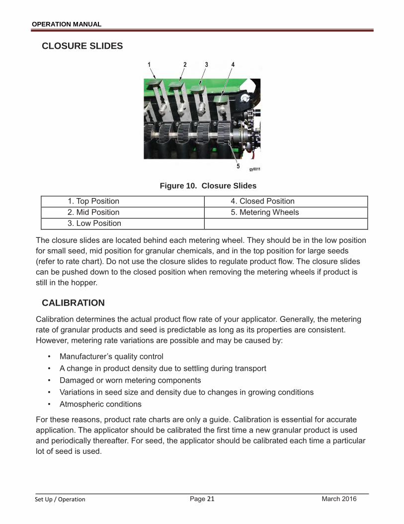
Figure 10. Closure Slides
1. Top Position 4. Closed Position 2. Mid Position 5. Metering Wheels 3. Low Position
The closure slides are located behind each metering wheel. They should be in the low position for small seed, mid position for granular chemicals, and in the top position for large seeds (refer to rate chart). Do not use the closure slides to regulate product flow. The closure slides can be pushed down to the closed position when removing the metering wheels if product is still in the hopper.
CALIBRATION
Calibration determines the actual product flow rate of your applicator. Generally, the metering rate of granular products and seed is predictable as long as its properties are consistent. However, metering rate variations are possible and may be caused by:
• Manufacturer’s quality control • A change in product density due to settling during transport • Damaged or worn metering components • Variations in seed size and density due to changes in growing conditions • Atmospheric conditions
For these reasons, product rate charts are only a guide. Calibration is essential for accurate application. The applicator should be calibrated the first time a new granular product is used and periodically thereafter. For seed, the applicator should be calibrated each time a particular lot of seed is used.

Page 22 March 2016
OPERATION MANUAL
Set Up / Operation
Steps:
1. After filling the hopper, set up a test course using two stakes placed 436 ft apart.
2. Read the label and cautionary statements of the granular chemical or recommended rates for the seed you are using. Determine the rate you need to apply in pounds per acre.
NOTE
Make sure the correct rate chart and the correct metering wheels are used for your application.
Figure 11. Zero-Max
1. Gauge 2. Arrow
3. Look up the rate chart for the material and deflector/tube spacing. Set the speed control on the applicator for your rate according to the chart. Make sure you align the arrow by viewing the gauge at eye level on the Zero-Max. (If no chart is available for your material, estimate a rate control setting based on a similar product in the rate chart.)
4. Place a plastic bag around each deflector tube end, securing it around the plastic tube,
leaving one-half of the top open to allow air to escape.

Page 23 March 2016
OPERATION MANUAL
Set Up / Operation
NOTE
Take precaution that bags are not dragged and torn while making the calibration run.
5. Start the blower. Adjust blower speed to produce 8-12 oz./in2 when applying granular chemical or light seed. With heavier products, higher air pressure may be required.
6. Travel the 436-ft course at anticipated field working speed.
7. Weigh the total contents of all the bags in pounds.
8. Divide the weight collected in pounds by the width of the implement in feet and multiply by 100 to get pounds per broadcast acre.
9. Adjust the Zero-Max speed control if needed and repeat steps 4-8.
Example
Weight of collected material from 24 outlets on 24 in. row spacing is 6 lbs. Divide pounds by width of implement (48) and multiply by 100.
24 outlets x 24 in. ÷ 12 = 48 ft
Then
6 lbs ÷ 48 x 100 = 12.5 lbs. per acre
Shortcut Method
If you wish to collect from fewer outlets rather than all the outlets, follow the same procedure as listed above to step 7. Then, use the formula as shown below.
Shortcut Example
Instead of all 24 outlets being used, only three outlets with 24 in. row spacing is used. A total of 0.75 lbs of product is collected. Total width of outlets used in the collection is 6 ft.
3 outlets x 24 in. ÷ 12 = 6 ft
Then,
6 ft of width x 436-ft. course ÷ 43,560 ft.2 = 0.06 test acres
0.75 lbs of collected product ÷ 0.06 test acres = 12.5 lbs per acre
Again, adjust the Zero-Max speed control if needed and repeat steps 4-7.

Page 24 March 2016
OPERATION MANUAL
Maintenance
MINTENANCE
This section provides information on daily and periodical maintenance of your applicator. Make sure to service all of these components after any lengthy period of non-use. You are responsible for the safe operation and maintenance of your applicator. Ensure that you and anyone else who is going to operate, maintain, or work on or around the applicator are familiar with the operating and maintenance procedures and related safety information contained in this manual.
ROUTINE MAINTENANCE / INSPECTION
Stop engine before performing any maintenance. Disconnect power source, and wait for all machine movement to stop before servicing, adjusting, cleaning, or unclogging the equipment. If the machine must be running to be properly serviced or maintained, the employer shall instruct employees as to all steps and procedures that are necessary to safely service or maintain equipment. Lock out electrical power before performing maintenance or service. Make sure everyone is clear of machinery before starting engine, engaging power, or operating machine.
HYDRAULIC BLOWER
CAUTION
Failure to provide regular inspection and maintenance may cause equipment failure and unsafe operation.
Inspect blower shaft bearings frequently for loose fasteners and misalignment. Replace and tighten fasteners as needed. After operation in dusty conditions, the air intake screen should be removed and the impeller blades cleaned to prevent accumulation of foreign matter that could interfere with fan operation.
Periodically inspect for excessive wear or cracks and check alignment of impeller shaft with the drive shaft. If the blower must be disassembled for any reason, refer to the Hydraulic Blower Assembly diagram in the Illustrated Parts & Packing List that came with your unit. The impeller is balanced at the factory. If imbalance occurs, replace impeller to prevent unsafe operation.

Page 25 March 2016
OPERATION MANUAL
Maintenance
BEARINGS
Check and clean bearings frequently for accumulation of dust or fine particles. Failure to do so may cause damage to shaft or sprockets. Binding of the shaft could cause a change in application rates.
MANIFOLD
CAUTION
Failure to clear accumulation of debris may interfere with air passage and delivery of material.
Make sure to clear manifold of collected dust or debris by daily removing expansion plugs in the manifold and blow out/remove dust and debris.
Page 26 March 2016
OPERATION MANUAL
Maintenance
LUBRICATION
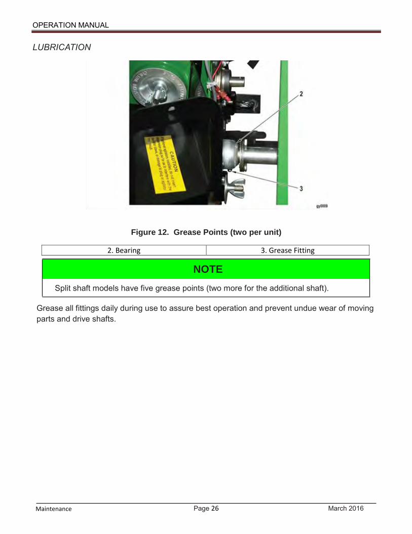
Figure 12. Grease Points (two per unit)
2. Bearing 3. Grease Fitting
NOTE
Split shaft models have five grease points (two more for the additional shaft).
Grease all fittings daily during use to assure best operation and prevent undue wear of moving parts and drive shafts.

Page 27 March 2016
OPERATION MANUAL
Maintenance
SAFETY
1. Refer to the Operator’s Manual for your machine. Follow all operating, maintenance, and safety information in the manual.
2. Place the implement on a firm, level surface. Lower all sections of the implement.
3. Exercise extreme caution when working around or with hydraulic systems. Depressurize the system when connecting or disconnecting the hose couplings.
4. Wear heavy gloves and a face shield for eye protection when searching for suspected
hydraulic leaks. A high-pressure concentrated stream of hydraulic fluid can pierce the skin. If such happens, seek immediate medical attention, as infection and toxic reaction could develop.
5. Do not attempt any adjustments or maintenance to any system of the applicator when the
implement is in motion.
6. Make sure all guards and shields are in place when the applicator is being operated.
7. Never wear ill-fitting, baggy or frayed clothing when working on any drive system components.
8. Store and transfer gasoline, solvents, cleaners, or any flammable liquids only in Safety
Standard-approved containers.
For Clutched Models
Components
An electric clutch consists of three primary components:
1. Coil Assembly The clutch’s “power” source contains the coil which generates magnetic force and requires a 12-volt DC coil.
2. Rotor Assembly Generally, the input of the clutch includes a keyed hub that mates with the keyway in the drive shaft. The rotor transmits torque from the drive shaft to the output or armature assembly.
3. Armature Assembly The output of the clutch also contains the mechanical brake in a clutch/brake assembly. The armature transmits torque from the rotor to the driven load. The sleeve is a secondary component serving as a spacer between the rotor and field assembly and also as a support for the field assembly bearing.
Page 28 March 2016
OPERATION MANUAL
Maintenance
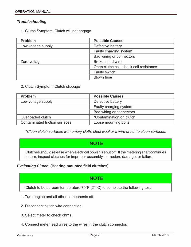
Troubleshooting
1. Clutch Symptom: Clutch will not engage
Problem Possible Causes Low voltage supply Defective battery
Faulty charging system Bad wiring or connectors
Zero voltage Broken lead wire Open clutch coil, check coil resistance
Faulty switch Blown fuse
2. Clutch Symptom: Clutch slippage
Problem Possible Causes Low voltage supply Defective battery
Faulty charging system Bad wiring or connectors
Overloaded clutch *Contamination on clutch Contaminated friction surfaces Loose mounting bolts
*Clean clutch surfaces with emery cloth, steel wool or a wire brush to clean surfaces.
NOTE
Clutches should release when electrical power is shut off. If the metering shaft continues to turn, inspect clutches for improper assembly, corrosion, damage, or failure.
Evaluating Clutch (Bearing mounted field clutches)
NOTE
Clutch to be at room temperature 70°F (21°C) to complete the following test.
1. Turn engine and all other components off.
2. Disconnect clutch wire connection.
3. Select meter to check ohms.
4. Connect meter lead wires to the wires in the clutch connector.

Page 29 March 2016
OPERATION MANUAL
Maintenance
5. If meter reads below 2.40 ohms or above 2.90 ohms, then the clutch has failed and needs to be replaced. If the meter reads between 2.40 ohms and 2.90 ohms, the problem is in the electrical system leading to the clutch (battery, relay, switch, wiring, etc.).
Interchanging Metering Wheels
Each unit is furnished with two sets of metering wheels (red in place and black as extra). They may be interchanged following this procedure:
1. Loosen the two hex bolts on the flangette bearing at each end.
2. Lift out shaft and wheel assembly (on ganged cup models, slide shaft assembly out the side after removing sprocket and bearing on drive end).
3. Remove metering wheels from shaft.
4. Slide on new set of metering wheels, aligning them in metering cups.
5. Replace flangettes and locking collar on outside of mounting plate tab.
6. Tighten hex bolts on each flangette bearing, then lock.

Page 30 March 2016
OPERATION MANUAL
Maintenance
DEFLECTOR PACKAGES
Instructions for mounting deflectors are shipped with each deflector package. Spacing for the different Turbo-Till / Chopper & Turbo-Max models listed below. Turbo-Max & Turbo-Till / Choppers 24-Ft models: 29-1/2 inches center to center. Turbo Max-& Turbo-Till / Chopper 30-Ft models: 30-5/8 inches center to center. Turbo-Max 35-Ft model: 30-1/2 inches center to center.
Page 31 March 2016
OPERATION MANUAL
Maintenance
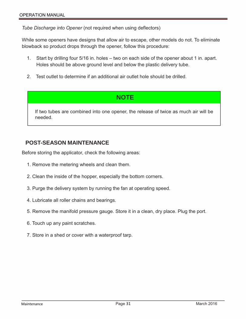
Tube Discharge into Opener (not required when using deflectors)
While some openers have designs that allow air to escape, other models do not. To eliminate blowback so product drops through the opener, follow this procedure:
1. Start by drilling four 5/16 in. holes – two on each side of the opener about 1 in. apart.
Holes should be above ground level and below the plastic delivery tube.
2. Test outlet to determine if an additional air outlet hole should be drilled.
NOTE
If two tubes are combined into one opener, the release of twice as much air will be needed.
POST-SEASON MAINTENANCE
Before storing the applicator, check the following areas:
1. Remove the metering wheels and clean them.
2. Clean the inside of the hopper, especially the bottom corners.
3. Purge the delivery system by running the fan at operating speed.
4. Lubricate all roller chains and bearings. 5. Remove the manifold pressure gauge. Store it in a clean, dry place. Plug the port.
6. Touch up any paint scratches.
7. Store in a shed or cover with a waterproof tarp.

Page 32 March 2016
OPERATION MANUAL
Maintenance
PRE-SEASON MAINTENANCE
Before starting the season’s work, check the following areas:
Bearings
• Inspect the fan bearing and couplers for signs of damage caused by heat. • Turn the metering system by hand. If there is any binding or dragging, replace the worn
bearing(s).
Delivery System
• Inspect the applicator for accumulation of debris. Clean if necessary. • Install the manifold pressure gauge. Run the fan to ensure it is working properly. • Run the fan at operating speed and check the air flow in each outlet.
Metering System
• Disassemble the electric clutches and buff the internal surfaces with emery cloth, steel wool, or a wire brush.
• Inspect individual metering wheels for wear. • Check sprockets for any damage to teeth. • Examine chains for tension and alignment. • Inspect Zero-Max Controller for signs of leakage.

Page 33 March 2016
OPERATION MANUAL
Maintenance
TROUBLESHOOTING Application Rates
Condition Solution Individual shutoff slides in incorrect position Position properly (open, closed, and two
intermediate positions Mathematical error made during field cali- bration
Recheck calculations
Catch sample not weighed accurately Weigh sample again Actual acreage less or more than calculated Check area covered Incorrect setting Check control setting or meter calibration Sprockets or chains slipping Check tightness Sprockets are incorrect size or ratio Check sprocket assembly Density of material differs from rate chart Field calibrate Binding of metering shaft Check and clean bearings Zero-Max turning in non-preferred direction Since Zero-Max turns faster in non-pre-
ferred direction (marked by an arrow), com- pensate and lower the setting by checking application rate through calibration
Stripping of Sprocket Teeth
Condition Solution Binding of metering shaft Check and clean bearings
Product not Metering
Condition Solution Individual shutoff slides closed Open to correct position Tube is kinked Check tube routing Blockage at metering wheel Check and clean Material has bridged in hopper or mixing chamber
Loosen and agitate
Tube end is blocked and material is blowing back out of mixing chamber
Clear blockage. Check for tube kinking
Manifold opening is blocked Check and clean manifold by removing expansion plugs
Air pressure too low Check blower, increase rpm if gauge indi- cates

Page 34 March 2016
OPERATION MANUAL
Maintenance
Condition Solution Metering wheels not turning Check electric drive
Product Caking in Hopper, Tubes, Metering Wheels or on Deflectors
Condition Solution High humidity Clean and check periodically Water in hopper bottom Drain. Remove plug and thoroughly dry
hopper Water in manifold Clear mixing chambers, remove plug from
manifold; run blower until system dries
Chattering Noise Coming from Fan
Condition Solution Bearing dry or worn Replace Impeller out of balance Check and replace Impeller blades striking housing Shut down blower. Readjust or replace
Hydraulic Motor
Condition Solution Leaking Replace seal. Check for oil contaminants Hydraulic fan surges Oil flow from machine is too low or too high

Page 35 March 2016
OPERATION MANUAL
THIS PAGE INTENTIONALLY LEFT BLANK

Page 36
March 2016
OPERATION MANUAL
INDEX
A
Air Pressure Gauge, 20
B
Broadcast Applications, 30
C
Calibration, 21 Zero-Max, 22
Clutches, 27 Troubleshooting, 33
Control Unit, 19 Functionality, 19 Wiring Instructions, 15
D
Data Plate, 7
G
Grease Points, 26
H
Hydraulic Blower, 24
Hydraulics, 11 & 17
I
Introduction, 5
L
Lubrication, 26
M Maintenance
Inspection, 24 Lubrication, 26
Grease Points, 26 Post-Season, 33 Pre-Season, 32 Safety, 27
Metering Wheels, Interchanging, 29
O Outlets/Deflectors, 30
P Plate, Data, 7
Post-Season Maintenance, 33
Pre-Season Maintenance, 32
S Safety
Granular Chemical, 11 Hydraulic, 11 Information, 8 Storage, 12 Transport, 11
T Troubleshooting, General, 33
W Warranty, 6
Z Zero-Max, 7 & 22

Page 37 March 2016
OPERATION MANUAL
THIS PAGE INTENTIONALLY LEFT BLANK
![Dynamic Attachment Frame System...The Two Row Seeder [Complete] will utilize Earthway 1001-B Precision Seeders. Each seeder connection will allow for easy removal Each seeder connection](https://static.fdocuments.us/doc/165x107/5f0e04877e708231d43d3603/dynamic-attachment-frame-system-the-two-row-seeder-complete-will-utilize-earthway.jpg)