Gravitation search algorithm: Application to the optimal ...
13
ORIGINAL ARTICLE Gravitation search algorithm: Application to the optimal IIR filter design Suman Kumar Saha a , Rajib Kar a, * , Durbadal Mandal a , S.P. Ghoshal b a Department of Electronics and Communication Engineering, National Institute of Technology, Durgapur, West Bengal, India b Department of Electrical Engineering, National Institute of Technology, Durgapur, West Bengal, India Received 1 March 2012; accepted 18 December 2012 Available online 26 December 2012 KEYWORDS IIR filter; GSA; Evolutionary optimization techniques; Stability Abstract This paper presents a global heuristic search optimization technique known as Gravita- tion Search Algorithm (GSA) for the design of 8th order Infinite Impulse Response (IIR), low pass (LP), high pass (HP), band pass (BP) and band stop (BS) filters considering various non-linear char- acteristics of the filter design problems. This paper also adopts a novel fitness function in order to improve the stop band attenuation to a great extent. In GSA, law of gravity and mass interactions among different particles are adopted for handling the non-linear IIR filter design optimization problem. In this optimization technique, searcher agents are the collection of masses and interac- tions among them are governed by the Newtonian gravity and the laws of motion. The perfor- mances of the GSA based IIR filter designs have proven to be superior as compared to those obtained by real coded genetic algorithm (RGA) and standard Particle Swarm Optimization (PSO). Extensive simulation results affirm that the proposed approach using GSA outperforms over its counterparts not only in terms of quality output, i.e., sharpness at cut-off, smaller pass band ripple, higher stop band attenuation, but also the fastest convergence speed with assured stability. ª 2013 Production and hosting by Elsevier B.V. on behalf of King Saud University. 1. Introduction Signal processing is the subject of pinnacle importance in the blossoming field of science and technology. A signal is the car- rier of information and signal processing deals with the analysis and processing of signals to extract or modify the information present in them. Requirement of signal processing is of prime importance due to noise entrapment or impairment of direct usage of information within the signal. Signals are broadly clas- sified as analog and digital ones. Analog signals are continuous functions of time and analog signal processing (ASP) is used for the analysis of such kind of signals for analog systems. On the other hand, digital signal processing (DSP) is useful for han- dling discrete time signal for digital systems in which filtering holds a significant position. Application of the filter is not only widely covered but also deeply rooted in its domain of utiliza- tion. Application is ranging from ripple reduction of a very sim- ple rectifier circuit to highly sophisticated application zones of biological and astrological signal analysis along with noise reduction of raw signal, video signal enhancement and graphic equalization in hi-fi systems. Basically, a filter is a frequency * Corresponding author. Tel.: +91 9434788056; fax: +91 343 2547375. E-mail addresses: [email protected] (R. Kar), durbadal.bittu@ gmail.com (D. Mandal). Peer review under responsibility of King Saud University. Production and hosting by Elsevier Journal of King Saud University – Engineering Sciences (2014) 26, 69–81 King Saud University Journal of King Saud University – Engineering Sciences www.ksu.edu.sa www.sciencedirect.com 1018-3639 ª 2013 Production and hosting by Elsevier B.V. on behalf of King Saud University. http://dx.doi.org/10.1016/j.jksues.2012.12.003 brought to you by CORE View metadata, citation and similar papers at core.ac.uk provided by Elsevier - Publisher Connector
Transcript of Gravitation search algorithm: Application to the optimal ...

Journal of King Saud University – Engineering Sciences (2014) 26, 69–81
brought to you by COREView metadata, citation and similar papers at core.ac.uk
provided by Elsevier - Publisher Connector
King Saud University
Journal of King Saud University – Engineering Sciences
www.ksu.edu.sawww.sciencedirect.com
ORIGINAL ARTICLE
Gravitation search algorithm: Application to the optimal
IIR filter design
Suman Kumar Saha a, Rajib Kar a,*, Durbadal Mandal a, S.P. Ghoshal b
a Department of Electronics and Communication Engineering, National Institute of Technology, Durgapur, West Bengal, Indiab Department of Electrical Engineering, National Institute of Technology, Durgapur, West Bengal, India
Received 1 March 2012; accepted 18 December 2012Available online 26 December 2012
*
25E
gm
Pe
10
ht
KEYWORDS
IIR filter;
GSA;
Evolutionary optimization
techniques;
Stability
Corresponding author. Te
47375.-mail addresses: rajibkarece
ail.com (D. Mandal).
er review under responsibilit
Production an
18-3639 ª 2013 Production
tp://dx.doi.org/10.1016/j.jksu
l.: +91
@gmail.c
y of King
d hostin
and hosti
es.2012.1
Abstract This paper presents a global heuristic search optimization technique known as Gravita-
tion Search Algorithm (GSA) for the design of 8th order Infinite Impulse Response (IIR), low pass
(LP), high pass (HP), band pass (BP) and band stop (BS) filters considering various non-linear char-
acteristics of the filter design problems. This paper also adopts a novel fitness function in order to
improve the stop band attenuation to a great extent. In GSA, law of gravity and mass interactions
among different particles are adopted for handling the non-linear IIR filter design optimization
problem. In this optimization technique, searcher agents are the collection of masses and interac-
tions among them are governed by the Newtonian gravity and the laws of motion. The perfor-
mances of the GSA based IIR filter designs have proven to be superior as compared to those
obtained by real coded genetic algorithm (RGA) and standard Particle Swarm Optimization
(PSO). Extensive simulation results affirm that the proposed approach using GSA outperforms over
its counterparts not only in terms of quality output, i.e., sharpness at cut-off, smaller pass band
ripple, higher stop band attenuation, but also the fastest convergence speed with assured stability.ª 2013 Production and hosting by Elsevier B.V. on behalf of King Saud University.
1. Introduction
Signal processing is the subject of pinnacle importance in theblossoming field of science and technology. A signal is the car-rier of information and signal processing deals with the analysis
and processing of signals to extract or modify the information
9434788056; fax: +91 343
om (R. Kar), durbadal.bittu@
Saud University.
g by Elsevier
ng by Elsevier B.V. on behalf of K
2.003
present in them. Requirement of signal processing is of primeimportance due to noise entrapment or impairment of direct
usage of information within the signal. Signals are broadly clas-sified as analog and digital ones. Analog signals are continuousfunctions of time and analog signal processing (ASP) is used for
the analysis of such kind of signals for analog systems. On theother hand, digital signal processing (DSP) is useful for han-dling discrete time signal for digital systems in which filtering
holds a significant position. Application of the filter is not onlywidely covered but also deeply rooted in its domain of utiliza-tion. Application is ranging from ripple reduction of a very sim-
ple rectifier circuit to highly sophisticated application zones ofbiological and astrological signal analysis along with noisereduction of raw signal, video signal enhancement and graphicequalization in hi-fi systems. Basically, a filter is a frequency
ing Saud University.
70 S.K. Saha et al.
selective device which extracts the useful portion of input signallying within its operating frequency range which could be con-taminated with random noise due to unavoidable circum-
stances. On the basis of physical makeup and the wayfiltration is done, filters are broadly classified as analog and dig-ital ones. Analog filters are made up with discrete components
like resistor, capacitor, inductor and op-amp. Discrete compo-nent dependent design, prone to high component tolerance sen-sitivity, poor accuracy, highly susceptible to thermal drift and
large physical size are the major retractions of analog filterimplementation. On the contrary, digital filter performs math-ematical operations on a sampled, discrete timed signal toachieve the desired features with the help of a specially designed
digital signal processor (DSP) chip or a processor used in a gen-eral purpose computer.
Digital filters are broadly classified into two main categories
namely; finite impulse response (FIR) filter and infinite im-pulse response (IIR) filter (Oppenheim et al., 1999; Proakisand Manolakis, 1996). The output of FIR filter depends on
present and past values of input, so the name non-recursiveis aptly suited to this filter. On the other hand, the output ofIIR filter depends not only on previous inputs, but also on pre-
vious outputs with impulse responses continuing forever intime at least theoretically, so the name ‘recursive’ is aptly sui-ted to this filter; anyway, a large memory is required to storethe previous outputs for the recursive IIR filter. Hence, due
to these aspects FIR filter realization is easier with the require-ment of less memory space and design complexity. Ensuredstability and linear phase response over a wide frequency range
are the additional advantages. On the other hand, IIR filterdistinctly meets the desired specifications of sharp transitionwidth, lower pass band ripple and higher stop band attenua-
tion with lower order as compared to the FIR filter. As a con-sequence, properly designed IIR filter can meet the magnituderesponse close to ideal and more finely as compared to FIR fil-
ter though stability is always to be ensured. Due to these chal-lenging features with a wide field of applications, performancesof IIR filters designed with various evolutionary optimizationalgorithms are compared to find out the comparative effective-
ness of the algorithms and the best optimal IIR filters.In the conventional approach, IIR filters of various types
(Butterworth, Chebyshev and Elliptic, etc.) can be imple-
mented with two methods. In the first case frequency samplingtechnique is adopted for Least Square Error (Lang, 2000) andRemez Exchange (Jackson and Lemay, 1990) process. In the
second method, filter coefficients and minimum order are cal-culated for a prototype low pass filter in analog domain whichis then transformed into digital domain with bilinear transfor-mation. This frequency mapping works well at low frequency,
but in high frequency domain this method is liable to fre-quency warping (Hussain et al., 2011).
IIR filter design is a challenging optimization problem. So
far, gradient based classical algorithms such as steepest descentand quasi Newton algorithms have been used aptly for the de-sign of IIR filters (Antoniou, 2005; Lu and Antoniou, 2000). In
general, these algorithms are very fast and efficient to obtainthe optimum solution of the objective function for a unimodalproblem. But the error surface (typically the mean square error
between the desired response and estimated filter output) ofIIR filter is multimodal and hence superior evolutionary opti-mization techniques are required to find out better globalsolution.
The shortfalls of classical optimization techniques for han-dling any multimodal optimization problem are as follows: (i)Requirement of continuous and differentiable error fitness
function (cost or objective function), (ii) Usually convergesto the local optimum solution or revisits the same sub-optimalsolution, (iii) Incapable to search the large problem space, (iv)
Requirement of the piecewise linear cost approximation (linearprogramming) and (v) Highly sensitive to starting points whenthe number of solution variables is increased and as a result the
solution space is also increased.So, it can be concluded that classical search techniques are
only suitable for handling differentiable unimodal objectivefunction with a constricted search space. So, the various evolu-
tionary heuristic search algorithms applied for filter optimiza-tion problems in recent times are as follows: GeneticAlgorithm (GA) is inspired by the Darwin’s ‘‘Survival of the
Fittest’’ strategy (Karaboga and Cetinkaya, 2004; Tsai et al.,2006; Yu and Xinjie, 2007); Simulated Annealing (SA) is de-signed from the thermodynamic effects (Chen et al., 2001);
Artificial Immune Systems (AIS) mimic the biological immunesystems (Kalinli and Karaboga, 2005); Ant Colony Optimiza-tion (ACO) simulates the ants’ food searching behavior
(Karaboga et al., 2004); Bee Colony Optimization mimicsthe honey collecting behavior of the bee swarm (Karabogaand Cetinkaya, 2011); Cat Swarm Optimization (CSO) isbased upon the behavior of cats for tracing and seeking of
an object (Panda et al., 2011); and Particle Swarm Optimiza-tion (PSO) simulates the behavior of bird flocking or fishschooling (Pan and Chang, 2011; Das and Konar, 2007; Fang
et al., 2009; Gao et al., 2008; Sun et al., 2010; Chen and Luk,2010; Luitel and Venayagamoorthy, 2008a,b; Mandal et al.,2011, 2012; Wang et al., 2011); in Quantum behaved PSO
(QPSO) quantum behavior of particles in a potential well isadopted in conventional PSO algorithm (Fang et al., 2009;Gao et al., 2008; Sun et al., 2010); to get rid of premature con-
vergence and stagnation, chaotic perturbation is applied on theparticles in Chaos PSO (CPSO) optimization technique (Gaoet al., 2008); Differential Evolution PSO (DEPSO) is thehybridization of DE and PSO in which new offspring is created
by the mutation of parent (Luitel and Venayagamoorthy,2008a,b); in Craziness based PSO (CRPSO), sudden directionchanging behavior of a particle in a swarm is mimicked in the
conventional velocity equation of PSO with the incorporationof ‘craziness factor’ (Mandal et al., 2011, 2012).
In this paper, the capability of global searching and near
optimum result finding features of RGA, PSO and GSA areindividually investigated thoroughly for solving 8th orderIIR filter design problems. GA is a probabilistic heuristicsearch optimization technique developed by Holland (Holland,
1975). The features such as multi-objective, coded variable andnatural selection made this technique distinct and suitable forfinding the near global solution of filter coefficients.
Particle Swarm Optimization (PSO) is swarm intelligencebased algorithm developed by Kennedy and Eberhart (1995)and Eberhart and Shi (1998). Several attempts have been taken
to design digital filter with basic PSO and its modified versions(Pan and Chang, 2011; Das and Konar, 2007; Fang et al.,2009; Gao et al., 2008; Sun et al., 2010; Chen and Luk,
2010; Luitel and Venayagamoorthy, 2008a,b; Mandal et al.,2011, 2012; Wang et al., 2011). The main attraction of PSOis its simplicity in computation and a few steps are requiredin the algorithm.
Gravitation search algorithm: Application to the optimal IIR filter design 71
The limitations of the conventional PSO are premature con-vergence and stagnation problem (Ling et al., 2008; Biswalet al., 2009). To overcome these problems a recently proposed
evolutionary optimization technique called gravitation searchalgorithm (GSA) is suggested by the authors for the designof 8th order LP, HP, BP and BS IIR filters.
The paper is organized as follows: Section 2 describes theIIR filter design problem. Different evolutionary algorithmsnamely, RGA, PSO and GSA along their comparative results
are discussed in Section 3. Section 4 discusses the simulationresults obtained for the designed IIR filter using different algo-rithms. Finally Section 5 concludes the paper.
2. IIR filter design formulation
This section discusses the design strategy of IIR filters. The in-put–output relation is governed by the following differenceequation (Proakis and Manolakis, 1996):
yðpÞ þXnk¼1
akyðp� kÞ ¼Xmk¼0
bkxðp� kÞ ð1Þ
where x(p) and y(p) are the filter’s input and output, respec-
tively and n(Pm) is the filter’s order. With the assumption ofcoefficient a0 = 0 the transfer function of the IIR filter is ex-pressed as:
HðzÞ ¼
Xmk¼0
bkz�k
1þXnk¼1
akz�kð2Þ
Let z = ejX. Then the frequency response of the IIR filter
becomes
HðXÞ ¼
Xmk¼0
bke�jkX
1þXnk¼1
ake�jkXð3Þ
or,
HðXÞ ¼ YðXÞXðXÞ ¼
b0 þ b1e�jX þ b2e
�j2X þ :::þ bme�jmX
1þ a1e�jX þ a2e�j2X þ :::þ bne�jnXð4Þ
where X ¼ 2p ffs
� �in [0, p] is the digital frequency; f is the ana-
log frequency and fs is the sampling frequency. Different fit-ness functions are used for IIR filter optimization problem(Karaboga and Cetinkaya, 2004; Luitel and Venayagamoor-
thy, 2008a,b). The commonly used approach to IIR filterdesign is to represent the problem as an optimization problemwith the mean square error (MSE) as the error fitness function
(Karaboga and Cetinkaya, 2004; Luitel and Venayagamoor-thy, 2008a,b), expressed in (5).
J1ðxÞ ¼1
Ns
½ðdðpÞ � yðpÞÞ2� ð5Þ
where Ns is the number of samples used for the computation of
the error fitness function; d(p) and y(p) are the filter’s desiredand actual responses, respectively. The differencee(p) = d(p) � y(p) is the error between the desired and the ac-
tual filter responses. The design goal is to minimize the MSE
J1(x) with proper adjustment of coefficient vector x repre-
sented as:
x ¼ ½a0a1:::anb0b1:::bm�T ð6Þ
In this paper, a novel error fitness function given in (7) isadopted in order to achieve higher stop band attenuationand to have better control on the transition width. Using (7),it is found that the filter design approach results in consider-
able improvement in stop band attenuation over other optimi-zation techniques.
J2ðxÞ ¼X
x
abs½absðjHdðxÞj � 1Þ � dp� þX
x
½absðjHdðwÞj � dsÞ�
ð7Þ
For the first term of (7), xe pass band including a portion of
the transition band and for the second term of (7), xe stopband including the rest portion of the transition band. Theportions of the transition band chosen depend on pass band
edge and stop band edge frequencies.The error fitness function given in (7) represents the gener-
alized fitness function to be minimized using the evolutionaryalgorithms RGA, conventional PSO, and the proposed GSA
individually. Each algorithm tries to minimize this error fitnessJ2(x) and thus optimizes the filter performance. Unlike othererror fitness functions as given in Karaboga and Cetinkaya
(2004) and Luitel and Venayagamoorthy, 2008a,b which con-sider only the maximum errors, J2(x) involves summation ofall absolute errors for the whole frequency band, and minimi-
zation of J2(x) yields much higher stop band attenuation andlesser pass band and stop band ripples.
3. Evolutionary optimization algorithms employed
Evolutionary optimization algorithms stand upon the platformof heuristic search methods, which are characterized by fea-
tures as stochastic, adaptive and learning in order to produceintelligent optimization schemes. Such schemes have the poten-tial to adapt to their ever changing dynamic environmentthrough the previously acquired knowledge. Few such efficient
algorithms are discussed for the purpose of designing as well ascomparison of performances for handling the optimizationproblem of design of IIR filters.
3.1. Real coded genetic algorithm (RGA)
Standard Genetic Algorithm (also known as real coded GA) is
mainly a probabilistic search technique, based on the princi-ples of natural selection and evolution built upon the Darwin’s‘‘Survival of the Fittest’’ strategy (Holland, 1975). Each en-
coded chromosome that constitutes the population is a solu-tion to the filter designing optimization problem.
Steps of RGA as implemented for the optimization ofcoefficient vector x are as follows (Mondal et al., 2010, 2011;
Mandal et al., 2012):
Step 1: Initialize the real coded chromosome strings (x) of
np population, each consisting of equal number of numera-tor and denominator filter coefficients bk and ak, respec-tively; total coefficients = (n+ 1) · 2 for nth order filter
to be designed; minimum and maximum values of the coef-

72 S.K. Saha et al.
ficients are �2 and +2, respectively; number of
samples = 128; dp = 0.01, ds = 0.001.Step 2: Decoding of the strings and evaluation of errorfitness values J2(x) according to (7).
Step 3: Selection of elite strings in order of increasing errorfitness values from the minimum value.Step 4: Copying the elite strings over the non-selectedstrings.
Step 5: Crossover and mutation generate offsprings.Step 6: Genetic cycle updating.Step 7: The iteration stops when maximum number of
cycles is reached. The grand minimum error fitness andits corresponding chromosome string or the desired solu-tion having (n+ 1) · 2 number of filter coefficients are
finally obtained.
3.2. Particle Swarm Optimization (PSO)
PSO is flexible, robust, population based stochastic searchalgorithm with attractive features of simplicity in implementa-tion and ability to quickly converge to a reasonably good solu-
tion. Additionally, it has the capability to handle larger searchspace and non-differential objective function, unlike tradi-tional optimization methods. Kennedy and Eberhart (1995)
and Eberhart and Shi (1998) developed PSO algorithm to sim-ulate random movements of bird flocking or fish schooling.
The algorithm starts with the random initialization of a
swarm of individuals, which are known as particles withinthe multidimensional problem search space, in which each par-ticle tries to move toward the optimum solution, where nextmovement is influenced by the previously acquired knowledge
of particle best and global best positions once achieved by indi-vidual and the entire swarm, respectively.
To some extent, IIR filter design and other designs with
PSO are already reported in Pan and Chang (2011), Das andKonar (2007), Fang et al. (2009), Gao et al. (2008), Sunet al. (2010), Chen and Luk (2010), Luitel and Venayagamoor-
thy (2008a,b) and Mandal et al. (2011, 2012).The basic steps of the PSO algorithm are as follows
(Mandal et al., 2011, 2012):
Step 1: Initialize the real coded particles (x) of np popula-tion, each consists of equal number of numerator anddenominator filter coefficients bk and ak, respectively; total
coefficients D= (n+ 1) · 2 for nth order filter to bedesigned; minimum and maximum values of the coefficientsare �2 and +2, respectively; number of samples = 128;
dp = 0.01; ds = 0.001; Vmax and Vmin values.Step 2: Compute the error fitness value for the current posi-tion Si of each particle.
Step 3:Each particle can remember its best position (pbest)which is known as cognitive information and that would beupdated with each iteration.Step 4: Each particle can also remember the best position
the swarm has ever attained (gbest) and is called socialinformation and would be updated in each iteration.Step 5: Velocity and position of each particle are modified
according to (8) and (10), respectively (Kennedy and Eber-hart, 1995).
Vðkþ1Þi ¼ w � VðkÞi þ C1 � rand1 � fpbestðkÞi � S
ðkÞi g þ C2
� rand2 � fgbestðkÞi � SðkÞi g ð8Þ
where Vi ¼ Vmax for Vi > Vmax ¼ Vmin for Vi
< Vmin ð9Þ
Sðkþ1Þi ¼ S
ðkÞi þ V
ðkþ1Þi ð10Þ
Step 6: The iteration stops when maximum number of
cycles is reached. The grand minimum error fitness andits corresponding particle or the desired solution having(n + 1) · 2 number of filter coefficients are finally obtained.
3.3. Gravitation search algorithm (GSA)
To overcome the problems of parameter convergence and stag-
nation associated with PSO (Ling et al., 2008; Biswal et al.,2009), this paper adopts one recently proposed novel evolu-tionary optimization algorithm known as gravitational search
algorithm (GSA) for the purpose of IIR digital filter design.In GSA (Rashedi et al., 2009, 2011; Bahrololoum et al.,
2012), agents/solution vectors are considered as objects and
their performances are measured by their masses. All these ob-jects attract each other by the gravity forces, and these forcesproduce a global movement of all objects towards the objects
with heavier masses. Hence, masses cooperate using a directform of communication through gravitational forces. The hea-vier masses (which correspond to better solutions) move moreslowly than lighter ones. This guarantees the exploitation step
of the algorithm.Three kinds of masses are defined in theoretical physics:
(a) Active gravitational mass (Ma) is a measure of thestrength of the gravitational field due to a particularobject. Gravitational field of an object with small active
gravitational mass is weaker than the object with moreactive gravitational mass.
(b) Passive gravitational mass (Mp) is a measure of thestrength of an object’s interaction with the gravitational
field. Within the same gravitational field, an object witha smaller passive gravitational mass experiences a smal-ler force than an object with a larger passive gravita-
tional mass.(c) Inertial mass (Mi) is a measure of an object’s resistance
to changing its state of motion when a force is applied.
An object with large inertial mass changes its motionmore slowly, and an object with small inertial masschanges it rapidly.
In GSA, each mass (agent) has four specifications: position,inertial mass, active gravitational mass, and passive gravita-tional mass. The position of the mass corresponds to the solu-
tion of the problem, and its gravitational and inertial massesare determined using a fitness function. In other words, eachmass presents a solution, the algorithm is navigated by prop-
erly adjusting the gravitational, and inertial masses. By lapseof iteration cycles, it is expected that masses be attracted by

Table 2 Control parameters of RGA, PSO and GSA.
Parameter RGA PSO GSA
Population size 120 25 25
Iteration cycles 500 500 500
Crossover rate 1.0 – –
Crossover Single Point Crossover – –
Mutation rate 0.01 – –
Mutation Gaussian Mutation – –
Selection Roulette – –
Selection probability 1/3 – –
C1 – 2.05 –
C2 – 2.05 –
vmini – 0.01 –
0maxi – 1.0 –
wmax – 1.0 –
wmin – 0.4 –
a – – 20
G0 – – 1000
rNORM – – 2
rPower – – 1
e – – 0.0001
0 0.1 0.2 0.3 0.4 0.5 0.6 0.7 0.8 0.9 1-80
-70
-60
-50
-40
-30
-20
-10
0
10
Frequency
Mag
nitu
de (d
B)
RGAPSOGSA
Figure 1 Gain plots in dB for 8th order IIR LP filter using
RGA, PSO and GSA.
0 0.1 0.2 0.3 0.4 0.5 0.6 0.7 0.8 0.9 10
0.2
0.4
0.6
0.8
1
1.2
1.4
Frequency
Mag
nitu
de (n
orm
aliz
ed)
RGAPSOGSA
Figure 2 Normalized gain plots for 8th order IIR LP filter using
RGA, PSO and GSA.
Table 1 Design specifications of IIR LP, HP, BP and BS filters.
Type of Filter Pass band
ripple (dp)Stop band
ripple (ds)Pass band normalized
edge frequencies (xp)
Stop band normalized
edge frequencies (xs)
LP 0.01 0.001 0.45 0.50
HP 0.01 0.001 0.35 0.30
BP 0.01 0.001 0.35 and 0.65 0.3 and 0.7
BS 0.01 0.001 0.25 and 0.75 0.3 and 0.7
Gravitation search algorithm: Application to the optimal IIR filter design 73
the heaviest mass. This heaviest mass will present an optimumsolution in the search space.
The GSA could be considered as an isolated system ofmasses. It is like a small artificial world of masses obeyingthe Newtonian laws of gravitation and motion. More precisely,
masses obey the following two laws.
i. Law of gravity: Each particle attracts every other parti-cle and the gravitational force between two particles isdirectly proportional to the product of their masses
and inversely proportional to the square of the distance(R) between them. R is used as RrPower (rPower = 1)because R offered better results than R2 in all the exper-
imental cases with benchmark functions.ii. Law of motion: The current velocity of any mass is equal
to the sum of the fraction of its previous velocity and the
variation in the velocity. Variation in the velocity oracceleration of any mass is equal to the force acted onthe system divided by the mass of inertia.
Now, let us consider a system with N agents (masses). Theposition of the ith agent is defined by
Xi ¼ ðx1i ; ::::::::x
di ; ::::::::x
ni Þ for i ¼ 1; 2; :::::::::N ð11Þ
where xdi presents the position of ith agent in the dth
dimension.At a specific iteration cycle t, the force acting on ith mass
from jth mass is defined as in the following equation
FdijðtÞ ¼ GðtÞMpiðtÞ �MajðtÞ
RijðtÞ þ eXd
j ðtÞ � Xdi ðtÞ
� �ð12Þ
where Maj(t) is the active gravitational mass related to the jthagent at iteration cycle t; Mpi(t) is the passive gravitationalmass related to the jth agent at iteration cycle t; G(t) is gravi-
tational constant at iteration cycle t; e is a small constant, and

Table 6 Radii of zeros for 8th order IIR LP filter.
Algorithm Zeros
Z1 Z2 Z3 Z4
GSA 0.937409 1.009397 0.983378 1.006001
-0.2
0
0.2
0.4
0.6
0.8
1
agin
ary
part
Pole/Zero plot using GSA for LP filter
Z1
Z2
Z3
Z4
Table 3 Optimized coefficients and performance comparison of concerned algorithms for 8th order IIR LP filter.
Algorithm Numerator Coefficients (bk) Denominator Coefficients (ak) Maximum Stop
band attenuation (dB)
RGA 0.0415 0.1234 0.2676 0.9994 �1.1555 2.7421 27.5145
0.3806 0.4206 0.3484 �2.3022 2.4552 �1.40370.2164 0.0925 0.0233 0.7776 �0.2480 0.0524
PSO 0.0413 0.1241 0.2668 1.0001 �1.1546 2.7413 30.3635
0.3791 0.4202 0.3478 �2.3016 2.4547 �1.40440.2165 0.0936 0.0235 0.7781 �0.2483 0.0519
GSA 0.0298 0.0778 0.1680 1.0001 �1.6888 3.3754 49.3552
0.2378 0.2717 0.2340 �3.4260 3.2805 �2.02490.1596 0.0739 0.0261 1.0290 �0.3239 0.0594
74 S.K. Saha et al.
Rij(t) is the Euclidian distance between the two agents i and jgiven by (13).
RijðtÞ ¼ kXiðtÞ;XjðtÞkrNorm rNormis usually 2 ð13Þ
To give a stochastic characteristic to the algorithm, it is ex-pected that the total force that acts on ith agent in dth dimen-sion be a randomly weighted sum of dth components of the
forces exerted from other agents given by (14).
Fdi ðtÞ ¼
XNj¼1;j–i
randjFdijðtÞ ð14Þ
where randj is a random number in the interval [0,1].
Hence, by the law of motion, the acceleration of the ithagent at iteration cycle t, and in dth dimension, adi ðtÞ is givenby (15).
adi ðtÞ ¼Fdi ðtÞ
MiiðtÞð15Þ
where Mii(t) is the inertial mass of the ith agent.Furthermore, the next velocity of an agent is considered as
a fraction of its current velocity added to its acceleration.Therefore, its position and its velocity can be calculated byemploying (16) and (17), respectively.
mdi ðtþ 1Þ ¼ randi � mdi ðtþ 1Þ þ adi ðtÞ ð16Þ
xdi ðtþ 1Þ ¼ xd
i ðtÞ þ mdi ðtþ 1Þ ð17Þ
Table 4 Statistical data for stop band attenuation (dB) for 8th
order IIR LP filter.
Algorithm Maximum Mean Variance Standard deviation
RGA 27.5145 40.3870 165.7013 12.8725
PSO 30.3635 46.5478 130.9666 11.4441
GSA 49.3552 53.1923 5.1670 2.2731
Table 5 Qualitatively analyzed data for 8th order IIR LP filter.
Algorithm Maximum pass band
ripple (normalized)
Stop band ripple (no
Maximum
RGA 0.0095 4.2100 · 10�2
PSO 0.0021 3.0300 · 10�2
GSA 0.0028 0.3406 · 10�2
In (16), randi is a uniform random variable in [0, 1]. This ran-dom number is utilized to give a randomized characteristic tothe search. The gravitational constant (G) is initialized at thebeginning and will be reduced with iteration cycle to control
the search accuracy. In other words, G as a function of the ini-tial value (G0) and iteration cycle (t) is expressed as in (18).
rmalized) Transition width
Minimum Average
15.7130 · 10�4 2.1836 · 10�2 0.0297
6.2811 · 10�4 1.5464 · 10�2 0.0338
1.2959 · 10�4 0.1768 · 10�2 0.0400
-1 -0.5 0 0.5 1
-1
-0.8
-0.6
-0.4
Real part
Im
Figure 3 Pole-zero plot of 8th order IIR LP filter using GSA.

0 0.1 0.2 0.3 0.4 0.5 0.6 0.7 0.8 0.9 1-90
-80
-70
-60
-50
-40
-30
-20
-10
0
10
Frequency
Mag
nitu
de (d
B)
RGAPSOGSA
Figure 4 Gain plots in dB for 8th order IIR HP filter using
RGA, PSO and GSA.
0 0.1 0.2 0.3 0.4 0.5 0.6 0.7 0.8 0.9 10
0.2
0.4
0.6
0.8
1
1.2
1.4
Frequency
Mag
nitu
de (n
orm
aliz
ed)
RGAPSOGSA
Figure 5 Normalized gain plots for 8th order IIR HP filter using
RGA, PSO and GSA.
Table 8 Statistical data for stop band attenuation (dB) for 8th
order IIR HP filter.
Algorithm Maximum Mean Variance Standard deviation
RGA 46.2199 49.8589 13.2467 2.6391
PSO 47.7018 50.7807 9.4796 3.0789
GSA 52.1714 53.3914 2.7025 1.6439
Table 7 Optimized coefficients and performance comparison of con
Algorithm Numerator coefficients (bk) D
RGA 0.1250 �0.7092 1.9588
�3.3672 3.9090 �3.1264 �1.6821 �0.5585 0.0881
PSO 0.1252 �0.7091 1.9587
�3.3671 3.9091 �3.1263 �1.6821 �0.5584 0.0881
GSA 0.1252 �0.7092 1.9587
�3.3672 3.9090 �3.1264 �1.6820 �0.5585 0.0882
Gravitation search algorithm: Application to the optimal IIR filter design 75
G ¼ G0 exp �a � t
maxcycles
� �� �ð18Þ
Gravitational and inertia masses are simply calculated by theerror fitness evaluation as defined by (7). A heavier mass meansamore efficient agent. Thismeans that better agents have higher
attractions and walk more slowly. Assuming the equality of thegravitational and the inertia mass, the values of masses arecalculated using the map of error fitness values. Gravitational
and inertial masses are updated by the following equations:
Mai ¼Mpi ¼Mii for i ¼ 1; 2; :::::::::N ð19Þ
miðtÞ ¼fitiðtÞ � worstðtÞbestðtÞ � worstðtÞ ð20Þ
MiðtÞ ¼miðtÞXN1
miðtÞð21Þ
where fiti(t) represents the error fitness value of the ith agent atiteration cycle t, and worst(t) and best(t) are defined in (22) and
(23), respectively, for the minimization problem as consideredin this work.
bestðtÞ ¼ minj2f1;...Ng
fitjðtÞ ð22Þ
worstðtÞ ¼ maxj2f1;...Ng
fitjðtÞ ð23Þ
One way to perform a good compromise between exploration
and exploitation is to reduce the number of agents with lapseof time in (14). Hence, it is supposed that a set of agents withbigger masses apply their forces to the other. However, this
policy is to be adopted carefully because it may reduce theexploration power and increase the exploitation capability.
cerned algorithms for 8th order IIR HP filter.
enominator coefficients (ak) Maximum stop
band attenuation (dB)
0.9999 �2.1875 3.8221 46.2199
3.6220 2.9095 �1.33320.5678 �0.0861 0.0285
1.0001 �2.1874 3.8222 47.7018
3.6220 2.9096 �1.33330.5678 �0.0861 0.0285
0.9999 �2.1875 3.8222 52.1714
3.6220 2.9095 �1.33330.5679 �0.0861 0.0285

Table 9 Qualitatively analyzed data for 8th Order IIR HP filter.
Algorithm Maximum pass band
ripple (normalized)
Stop band ripple (normalized) Transition width
Maximum Minimum Average
RGA 0.0146 0.48863 · 10�2 0.39587 · 10�4 0.24629 · 10�2 0.0598
PSO 0.0186 0.41201 · 10�2 0.47667 · 10�4 0.20839 · 10�2 0.0500
GSA 0.0207 0.24628 · 10�2 3.11350 · 10�4 0.13871 · 10�2 0.0518
-1 -0.5 0 0.5 1
-1
-0.8
-0.6
-0.4
-0.2
0
0.2
0.4
0.6
0.8
1
Real part
Imag
inar
y pa
rt
Pole/Zero plot using GSA for HP filter
Z1
Z2 Z3
Z4
Figure 6 Pole-zero plot of 8th order IIR HP filter using GSA.
Table 10 Radii of zeros for 8th Order IIR HP filter.
Algorithm Zeros
Z1 Z2 Z3 Z4
GSA 1.024214 0.967517 0.986437 0.858579
0 0.1 0.2 0.3 0.4 0.5 0.6 0.7 0.8 0.9 1-80
-70
-60
-50
-40
-30
-20
-10
0
10
Frequency
Mag
nitu
de (d
B)
RGAPSOGSA
Figure 7 Gain plots in dB for 8th order IIR BP filter using
RGA, PSO and GSA.
0 0.1 0.2 0.3 0.4 0.5 0.6 0.7 0.8 0.9 10
0.2
0.4
0.6
0.8
1
1.2
1.4
Frequency
Mag
nitu
de (n
orm
aliz
ed)
RGAPSOGSA
Figure 8 Normalized gain plots for 8th order IIR BP filter using
RGA, PSO and GSA.
76 S.K. Saha et al.
In order to avoid trapping into a local optimum, the algo-rithm must use the exploration at the beginning. By lapse ofiterations, exploration must fade out and exploitation must
fade in. To improve the performance of GSA by controllingexploration and exploitation only the Kbest agents will attractthe others. Kbest is a function of iteration cycle with the initial
value K0 and it decreases with iteration cycle. In such a way, allagents apply the force at the beginning, and as iteration cycleprogresses, Kbest is decreased linearly. At the end, there will bejust one agent applying force to the others. Therefore, (14)
could be modified as (24).
Fdi ðtÞ ¼
Xj2Kbest; j–i
randjFdijðtÞ ð24Þ
In (24), Kbest is the set of first K agents with the minimum er-ror fitness values and the biggest masses.
3.3.1. Implementation of the GSA for the IIR filter designproblem
The steps of the GSA, as implemented for the solution of IIRfilter design carried out in this work, are shown below:
Step 1: Initialization: population (swarm size) of agent vec-tors, np = 25; maximum iteration cycles = 500; for equal
number of numerator and denominator coefficients bkand ak, respectively; total coefficients = (n + 1) · 2 fornth order filter to be designed; minimum and maximum val-ues of the coefficients are �2 and +2, respectively; number
Table 12 Statistical data for stop band attenuation (dB) for
8th order IIR BP filter.
Algorithm Maximum Mean Variance Standard deviation
RGA 18.2445 20.3032 4.2382 2.0587
PSO 20.1389 21.4826 1.8054 1.3437
GSA 24.3104 24.5265 0.0467 0.2161
-1 -0.5 0 0.5 1
-1
-0.8
-0.6
-0.4
-0.2
0
0.2
0.4
0.6
0.8
1
Real part
Imag
inar
y pa
rt
Pole/Zero plot using GSA for BP filter
Z1
Z2 Z3
Z4
Figure 9 Pole-zero plot of 8th order IIR BP filter using GSA.
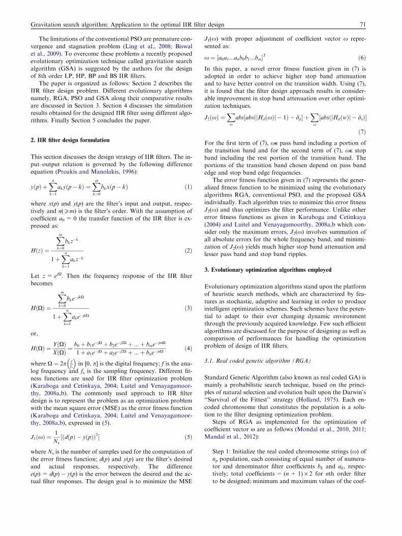
Table 14 Radii of zeros for 8th order IIR BP filter.
Algorithm Zeros
Z1 Z2 Z3 Z4
GSA 0.999874 1.000812 1.001116 0.999676
Table 11 Optimized coefficients and performance comparison of concerned algorithms for 8th order IIR BP filter.
Algorithm Numerator coefficients (bk) Denominator coefficients (ak) Maximum stop band
attenuation (dB)
RGA 0.1369 �0.0069 �0.0200 0.9971 �0.0075 1.5866 18.2445
�0.0043 0.1897 0.0069 �0.0094 1.7020 0.0000
�0.0338 �0.0056 0.1253 0.8246 �0.0025 0.2247
PSO 0.1274 0.0071 �0.0209 0.9927 �0.002 1.5940 20.1389
0.008 0.1857 0.0001 0.0029 1.6978 �0.0002�0.0292 �0.0052 0.1299 0.8079 �0.0034 0.2058
GSA 0.1040 �0.0003 �0.0158 1.0005 �0.0000 1.7574 24.3104
0.0006 0.1543 0.0005 0.0003 1.8299 0.0004
�0.0162 �0.0003 0.1043 0.8934 �0.0008 0.2168
Gravitation search algorithm: Application to the optimal IIR filter design 77
of samples = 128; dp = 0.01, ds = 0.001; a = 20; G0 =1000; rNorm = 2; rPower = 1; initial velocities = zeros
(np, (n + 1) · 2); e = 0.0001.Step 2: Generate initial agent vectors np having (n + 1) · 2number of filter coefficients h(n) randomly within limits.Step 3: Computation of error fitness values of the total pop-
ulation, np, as defined by (7).Step 4: Computation of the population based best solution(hgbest) vector.
Step 5: Update G(t), best(t), worst(t) and Mi(t) for i = 1, 2,..., np; t is current iteration cycle.Step 6: Calculation of the total forces in different
directions.Step 7: Calculation of accelerations and velocities of agents.Step 8: Updating agents’ positions.Step 9: Repeat Steps 3–8 until the stopping criterion (either
maximum iteration cycles or near global optimal solutionor agent, hgbest) is met.
Finally, hgbest is the vector of optimal filter coefficients(n+ 1) · 2. Extensive simulation study has been individuallyperformed for comparison of optimization performances of
three algorithms RGA, PSO and GSA, respectively, for the8th order LP, HP, BP and BS IIR filter optimization problems.The design specifications followed for all algorithms are given
in Table 1.
Table 13 Qualitatively analyzed data for 8th order IIR BP filter.
Algorithm Maximum pass band
ripple (normalized)
Stop band ripple (no
Maximum
RGA 0.0134 12.24 · 10�2
PSO 0.0399 9.84 · 10�2
GSA 0.0130 6.09 · 10�2
4. Results and discussions
The values of the control parameters of RGA, PSO and GSAare given in Table 2. Each algorithm is run for 30 times to get
the best solution and the best results are reported in this paper.
rmalized) Transition width
Minimum Average
12.0000 · 10�3 6.7200 · 10�2 0.0311
3.7771 · 10�3 5.1089 · 10�2 0.0277
0.1756 · 10�3 3.0538 · 10�2 0.0366

0 0.1 0.2 0.3 0.4 0.5 0.6 0.7 0.8 0.9 1-80
-70
-60
-50
-40
-30
-20
-10
0
10
Frequency
Mag
nitu
de (d
B)
RGAPSOGSA
Figure 10 Gain plots in dB for 8th order IIR BS filter using
RGA, PSO and GSA.
0 0.1 0.2 0.3 0.4 0.5 0.6 0.7 0.8 0.9 10
0.2
0.4
0.6
0.8
1
1.2
1.4
Frequency
Mag
nitu
de (n
orm
aliz
ed)
RGAPSOGSA
Figure 11 Normalized gain plots for 8th order IIR BS filter
using RGA, PSO and GSA.
Table 16 Statistical data for stop band attenuation (dB) for
8th order IIR BS filter.
Algorithm Maximum Mean Variance Standard deviation
RGA 17.4734 21.0867 13.0559 3.6133
PSO 21.9740 24.1658 4.8038 2.1918
GSA 24.7606 24.7761 0.0001 0.0116
78 S.K. Saha et al.
All optimization programs are run in MATLAB 7.5 version oncore (TM) 2 duo processor, 3.00 GHz with 2 GB RAM.
Table 15 Optimized coefficients and performance comparison of co
Algorithm Numerator coefficients (bk)
RGA 0.2269 �0.0189 0.5039
0.0170 0.6409 �0.01360.4866 0.0093 0.2189
PSO 0.2142 �0.0058 0.4833
�0.0008 0.6503 0.0097
0.4976 0.0041 0.2091
GSA 0.2215 0.0000 0.5175
0.0001 0.6995 �0.00000.5172 0.0001 0.2211
Three aspects of the algorithms are investigated in this worknamely, their accuracy, speed of convergence and stability.
Fig. 1 shows the comparative gain plots in dB for the designed8th order IIR LP filter obtained for different algorithms. Fig. 2represents the comparative normalized gain plots for 8th order
IIR LP filter. The best optimized numerator coefficients (bk)and denominator coefficients (ak) obtained are reported inTable 3. It is observed that maximum stop band attenuations
27.5145 dB, 30.3635 dB and 49.3552 dB are obtained forRGA, PSO and GSA algorithms, respectively. Gain plots andTables 4 and 5 also explore that the proposed 8th order IIR filterdesign using GSA attains the highest stop band attenuation, the
lowest stop band ripple, variance and standard deviation withappreciably small transition width and pass band ripple againstthe results produced by the rest algorithms (See Table 5). Table 6
shows the radii of zeros for the designed 8th order IIR LP filter.Fig. 3 shows the pole-zero plot for 8th order IIR LP filter de-
signed with the GSA algorithm. This figure demonstrates the
existence of poles within the unit circle which ensures thebounded input bounded output (BIBO) stability condition.Fig. 4 shows the comparative gain plot in dB for the 8th orderIIR HP filter with the individual application of RGA, PSO
and GSA optimization techniques, respectively. Fig. 5 repre-sents the comparative normalized gain plots for 8th order IIRHP filter. The best optimized numerator coefficients (bk) and
denominator coefficients (ak) obtained are reported in Table7. It has been observed that maximum stop band attenuations46.2199 dB, 47.7018 dB and 52.1714 dB are obtained for
RGA, PSO and GSA algorithms, respectively. Gain plots andTables 8 and 9 also prove that the proposed optimization tech-nique, GSA attains the highest stop band attenuation, lowest
stop band ripple along with the smallest variance and standarddeviation compared to the results produced by others.
Fig. 6 shows the pole-zero plot of 8th order IIR HP filterdesignedwith theGSAoptimization technique. It is noticed that
all poles are within the unit circle which ensures the stabilitycondition of designed filter. Radii of zeros located above the realpart of z plane are shown in Table 10.
ncerned algorithms for 8th order IIR BS filter.
Denominator coefficients (ak) Maximum stop band
attenuation (dB)
1.0190 �0.0067 0.0968 17.4734
0.0109 0.8671 0.0180
�0.0322 0.0177 0.1182
1.0073 �0.0069 0.0980 21.9740
�0.0077 0.8902 �0.0073�0.0198 �0.0048 0.1089
1.0000 �0.0001 0.1572 24.7606
0.0000 0.9085 0.0000
0.0055 �0.0001 0.1181

-1 -0.5 0 0.5 1
-1
-0.8
-0.6
-0.4
-0.2
0
0.2
0.4
0.6
0.8
1
Real part
Imag
inar
y pa
rt
Pole/Zero plot using GSA for BS filter
Z1Z2 Z3
Z4
Figure 12 Pole-zero plot of 8th order IIR BS filter using GSA.
Table 17 Qualitatively analyzed data for 8th order IIR BS filter.
Algorithm Maximum Pass band
ripple (normalized)
Stop band ripple (normalized) Transition width
Maximum Minimum Average
RGA 0.0268 13.38 · 10�2 30.6000 · 10�3 8.2200 · 10�2 0.0535
PSO 0.0303 7.97 · 10�2 5.8373 · 10�3 4.2769 · 10�2 0.0377
GSA 0.0063 5.78 · 10�2 0.2207 · 10�3 2.9010 · 10�2 0.0395
Table 18 Radii of zeros for 8th order IIR BS filter.
Algorithm Zeros
Z1 Z2 Z3 Z4
GSA 1.000006 0.999196 0.999862 0.999923
0 50 100 150 200 250 300 350 400 450 5001
2
3
4
5
6
7
8
9
Iteration Cycles
Erro
r Fitn
ess
RGAPSOGSA
Figure 13 Convergence profiles for RGA, PSO and GSA for 8th
order IIR LP filter.
Gravitation search algorithm: Application to the optimal IIR filter design 79
Comparative gain plots in dB are demonstrated in Fig. 7.Fig. 8 also represents the comparative normalized gain plots
for 8th order IIR BP filter designed by the optimization tech-niques. The best optimized numerator coefficients (bk) anddenominator coefficients (ak) obtained are reported in Table
11. It is observed that the maximum stop band attenuations
Table 19 Comparison of performance criteria attained by other rep
Reference Algorithm
considered
Filter type
Karaboga and Cetinkaya (2004) GA LP
Gao et al. (2008) CPSO LP
Luitel and Venayagamoorthy (2008a,b) PSO, DE-PSO LP
Luitel and Venayagamoorthy (2008a,b) PSO, PSO-QI LP
Wang et al. (2011) LS-MOEA LP, HP, BP, BS
Present paper GSA LP, HP, BP, BS
18.2445 dB, 20.1389 dB and 24.3104 dB are obtained forRGA, PSO and GSA optimization techniques, respectively.
Gain plots and Tables 12 and 13 also indicate that the pro-posed 8th order IIR filter design using GSA attains the higheststop band attenuation, lowest pass band and stop band ripples,
variance and standard deviation with significantly small transi-tion width as compared to the results produced by others.
Fig. 9 shows the pole-zero plot of 8th order IIR BP filterdesigned with GSA optimization technique. The designed filter
is stable due to the location of poles within the unit circle. Ra-dii of zeros located above the real part of z plane are reportedin Table 14.
Fig. 10 shows the comparative gain plot in dB for the 8thorder IIR BS filter with the application of RGA, PSO and
orted works.
Order Stop band
attenuation
(dB)
Pass band
ripple
Stop band
ripple
Transition
width
10th 14 – – –
8th 34 – – –
9th 25, 22 – –
9th 22, 27 – – –
11th – – 0.12, 0.16, 0.15, 0.05 –
8th 49.3552,
52.1714,
24.3104,
24.7606
0.0028,
0.0207,
0.0130,
0.0063
0.3406 · 10�2,
0.2462 · 10�2,
6.09 · 10�2,
5.78 · 10�2
0.04,
0.0518,
0.0366,
0.0395

Table 20 Convergence profile results for RGA, PSO and GSA for 8th order low pass IIR filter.
Algorithm Minimum error
value
Iteration
cycles
Convergence speed
(per cycle)
Execution time for
100 cycles (s)
RGA 4.054 500 8.608 · 10�3 7.795833
PSO 2.850 500 7.918 · 10�3 5.693405
GSA 1.825 500 11.530 · 10�3 4.037103
80 S.K. Saha et al.
GSA optimization techniques, respectively. Fig. 11 representsthe comparative normalized gain plots for 8th order IIR BS fil-
ter. The best optimized numerator coefficients (bk) and denomi-nator coefficients (ak) obtained after extensive simulation studyare reported in Table 15. It has been observed that maximum
stop band attenuations 17.4734 dB, 21.9740 dB and 24.7606 dBare obtained for RGA, PSO and GSA algorithms, respectively.Gain plots and Tables 16 and 17 also explore that the proposed
optimization technique, GSA attains the highest stop band atten-uation, smallest variance and standard deviation with lowest passband and stop band ripples and appreciably small transitionwidth compared to the results produced by others.
Fig. 12 shows the pole-zero plot of 8th order IIR BS filterdesigned with GSA optimization technique. The designed filteris stable due to the location of poles within the unit circle.
Radii of zeros located above the real part of z plane arereported in Table 18. Table 18 dictates the same inference ofnon minimum phase characteristic of the filter.
It is observed from Table 4 that the maximum stop bandattenuations 27.5145 dB, 30.3635 dB, and 49.3552 dB are ob-tained for RGA, PSO, and GSA algorithms, respectively, for8th order IIR LP filter design. In Gao et al. (2008) applied
CPSO technique for designing 8th order IIR LP filter and re-ported maximum stop band attenuation of approximately34 dB; in this work the proposed algorithm GSA shows much
more stop band attenuation. Luitel et al. reported the designof 9th order IIR LP filter using PSO and PSO-QI and approx-imate attenuations of 22 dB and 27 dB, respectively, have been
achieved in Luitel and Venayagamoorthy, 2008a,b. Luitel et al.in (Luitel and Venayagamoorthy, 2008a,b) reported for 9th or-der IIR LP filter using PSO and DEPSO in which maximum
attenuations approximately of 25 dB and 22 dB, respectively,have been reported. In this paper, maximum attenuation ob-tained for PSO is higher even though it is designed with lowerorder. In Karaboga and Cetinkaya (2004) have reported for
10th order minimum phase IIR LP filter of maximum attenua-tion approximately of 14 dB when GA is employed. In thiswork the maximum attenuation of 27.5145 dB for RGA with
lower order is achieved. In (Wang et al., 2011) Wang et al. havereported for the maximum stop band ripple of approximately0.12, 0.16, 0.15 and 0.05 for 11th order IIR LP, HP, BP and
BS filters when LS-MOEA technique is adopted. In this studywith RGA improved maximum results are obtained. TheGSA yields the improved stop band ripples even with lower
order IIR LP, HP, BP and BS filters, respectively, as 0.3406· 10�2, 0.24628 · 10�2, 6.09 · 10�2 and 5.78 · 10�2. The afore-mentioned results can be verified from Table 19.
4.1. Comparative effectiveness and convergence profiles of RGA,PSO and GSA
In order to compare the algorithms in terms of the error fitness
values, Fig. 13 depicts the comparative convergences of error
fitness values obtained by RGA, PSO and the GSA for the8th order IIR LP filter. Similar plots are also obtained for
the rest filters, which are not shown.As shown in Fig. 13, RGA converges to the minimum error
fitness value of 4.054 in 38.9791 s; PSO converges to the min-
imum error fitness value of 2.850 in 28.4670 s; whereas, GSAconverges to the minimum error fitness value of 1.825 in20.185515 s. The above-mentioned execution times may be ver-
ified from Table 20. Similar observations can be made for therest filters, which are not shown. Table 20 summarizes the con-vergence profile results for RGA, PSO and GSA applied forthe design of IIR LP filter.
From Fig. 13 it can be concluded that the proposed algo-rithm GSA obtains the minimum error fitness value as com-pared to PSO and RGA. It is also noticed that the proposed
algorithm, GSA has the faster rate of convergence in terms ofsharp reduction in error fitness value shown in Fig. 13, com-pared to the rest error fitness curves obtained by RGA and
PSO algorithms for obtaining the optimum results. With a viewto the above fact, it may finally be inferred that the perfor-mance of the GSA is the best among all the mentionedalgorithms. All optimization programs are run in MATLAB
7.5 version on core (TM) 2 duo processor, 3.00 GHz with2 GB RAM.
5. Conclusion
In this paper, a recently developed evolutionary optimizationalgorithm, GSA, based on interaction of masses and guided
by the law of gravity has been applied to the optimal designingof 8th order low pass, high pass, band pass and band stop IIRdigital filters. The optimal filters thus obtained meet the stabil-
ity criterion and show the best attenuation characteristics withreasonably good transition widths. The GSA converges veryfast to the best quality optimal solution and reaches the lowest
minimum error fitness value in a moderately low executiontime. Statistically improved results obtained for the GSA alsojustify the potential of the proposed algorithm for the realiza-tion of digital IIR filters.
References
Antoniou, A., 2005. Digital Signal Processing: Signals, Systems and
Filters. McGraw Hill.
Bahrololoum, A., Nezamabadi-pour, H., Bahrololoum, H., Saeed, M.,
2012. A prototype classifier based on gravitational search algo-
rithm. Appl. Soft Comput. 12 (2), 819–825.
Biswal, B., Dash, P.K., Panigrahi, B.K., 2009. Power quality disturbance
classification using fuzzy c-means algorithm and adaptive particle
swarm optimization. IEEE Trans. Ind. Electron. 56 (1), 212–220.
Chen, S., Luk, B.L., 2010. Digital IIR filter design using particle
swarm optimization. Int. J. Model. Ident. Control 9 (4), 327–335.
Chen, S., Istepanian, R., Luk, B.L., 2001. Digital IIR filter design using
adaptive simulated annealing. Digit. Signal Process. 11 (3), 241–251.

Gravitation search algorithm: Application to the optimal IIR filter design 81
Das, S., Konar, A., 2007. A swarm intelligence approach to the
synthesis of two-dimensional IIR filters. Eng. Appl. Artif. Intel. 20
(8), 1086–1096.
Eberhart, R., Shi, Y.,1998. Comparison between genetic algorithm and
particle swarm optimization. In: Evolutionary Programming VII,
Springer, pp. 611-616.
Fang, W., Sun, J., Xu, W., 2009. A new mutated quantum-behaved
particle swarm optimization for digital IIR filter design. EURASIP
J. Adv. Signal Process., 1–7.
Gao, Y., Li, Y., Qian, H., 2008. The design of IIR digital filter based
on chaos particle swarm optimization algorithm. IEEE Int. Conf.
Genet. Evol. Comput., 303–306.
Holland, J.H., 1975. Adaptation in Natural and Artificial Systems.
University of Michigan Press, Ann Arbor.
Hussain, Z.M., Sadik, A.Z., O’Shea, P., 2011. Digital Signal Processing
– An Introduction with MATLAB Applications. Springer-Verlag.
Jackson, L.B., Lemay, G.J., 1990. A simple Remez exchange algorithm
to design IIR filters with zeros on the unit circle. IEEE Int. Conf.
Acoust. Speech Signal Process. USA 3, 1333–1336.
Kalinli, A., Karaboga, N., 2005. Artificial immune algorithm for IIR
filter design. Eng. Appl. Artif. Intel. 18 (8), 919–929.
Karaboga, N., Cetinkaya, B., 2004. Design of minimum phase digital
IIR filters by using genetic algorithm. In: Proc. IEEE 6th Nordic
Signal Processing Symposium, June 2004, Finland, pp. 29–32.
Karaboga, N., Cetinkaya, M.H., 2011. A novel and efficient algorithm
for adaptive filtering: artificial bee colony algorithm. Turk. J. Elec.
Eng. Comp. Sci. 19 (1), 175–190.
Karaboga, N., Kalinli, A., Karaboga, D., 2004. Designing digital IIR
filters using ant colony optimization algorithm. Eng. Appl. Artif.
Intel. 17 (3), 301–309.
Kennedy, J., Eberhart, R., 1995. Particle swarm optimization. Proc.
IEEE Int. Conf. on Neural Network 4, 1942–1948.
Lang, M.C., 2000. Least-squares design of IIR filters with prescribed
magnitude and phase responses and pole radius constraint. IEEE
Trans. Signal Process. 48 (11), 3109–3121.
Ling, S.H., Iu, H.H.C., Leung, F.H.F., Chan, K.Y., 2008. Improved
hybrid particle swarm optimized wavelet neural network for
modelling the development of fluid dispensing for electronic
packaging. IEEE Trans. Ind. Electron. 55 (9), 3447–3460.
Lu, W.-S., Antoniou, A., 2000. Design of digital filters and filter banks
by optimization: a state of the art review. In: Proc. European Signal
Processing Conf., vol. 1, September 2000, Finland, pp. 351–354.
Luitel, B., Venayagamoorthy, G.K., 2008. Particle swarm optimization
with quantum infusion for the design of digital filters. In: IEEE
Swarm Intelligence Symposium, September 2008, St. Louis, MO
USA, pp. 1–8.
Luitel, B., Venayagamoorthy, G.K., 2008a. Differential evolution
particle swarm optimization for digital filter design. IEEE Congr.
Evol. Comput., 3954–3961.
Mandal, S., Ghoshal, S.P., Kar, R., Mandal, D., 2011. Optimal linear
phase FIR band pass filter design using craziness based particle
swarm optimization algorithm. J. Shanghai Jiaotong Univ. (Sci-
ence), Springer 16 (6), 696–703.
Mandal, S., Ghoshal, S.P., Kar, R., Mandal, D., 2012. Design of
optimal linear phase FIR high pass filter using craziness based
particle swarm optimization technique. J. King Saud Univ.
Comput. Inf. Sci. (Elsevier) 24, 83–92.
Mandal, S., Mandal, D., Kar, R., Ghoshal, S.P., 2012. Non-recursive
FIR band pass filter optimization by improved particle swarm
optimization. In: Int. Conf. on Information Systems Design and
Intelligent Applications-2012, (Springer-Verlag), AISC 132, India,
pp. 405–412.
Mondal, D., Ghosal, S.P., Bhattacharya, A.K., 2011. Application of
evolutionary optimization techniques for finding the optimal set of
concentric circular antenna array. Expert Syst. Appl. (Elsevier) 38
(4), 2942–2950.
Mondal, D., Ghosal, S.P., Bhattacharya, A.K., 2010. Radiation
pattern optimization for concentric circular antenna array with
central element feeding using craziness based particle swarm
optimization. International Journal of RF and Microwave Com-
puter-Aided Engineering (Wiley) 20 (5), 577–586.
Oppenheim, A.V., Schafer, R.W., Buck, J.R., 1999. Discrete-Time
Signal Processing. Prentice-Hall, NJ.
Pan, S.T., Chang, C.Y., 2011. Particle swarm optimization on D-stable
IIR filter design. In: IEEE World Congress on Intelligent Control
Automation, WCICA ’11, Taipei, pp. 621–626.
Panda, G., Pradhan, P.M., Majhi, B., 2011. IIR system identification
using cat swarm optimization. Expert Syst. Appl. 38 (10), 12671–
12683.
Proakis, J.G., Manolakis, D.G., 1996. Digital Signal Processing.
Prentice-Hall, NJ.
Rashedi, E., Nezamabadi-pour, H., Saryazdi, S., 2009. GSA: a
gravitational search algorithm. Inf. Sci. (Elsevier) 179 (13), 2232–
2248.
Rashedi, E., Nezamabadi-Pour, H., Saryazdi, S., 2011. Filter model-
ling using gravitational search algorithm. Eng. Appl. Artif. Intell.
(Elsevier) 24 (1), 117–122.
Sun, J., Fang, W., Xu, W., 2010. A quantum-behaved particle swarm
optimization with diversity-guided mutation for the design of two-
dimensional IIR digital filters. IEEE Trans. Circuits and Systems-II
57 (2), 141–145.
Tsai, J.T., Chou, J.H., Liu, T.K., 2006. Optimal design of digital IIR
filters by using hybrid Taguchi genetic algorithm. IEEE Trans. Ind.
Electron. 53 (3), 867–879.
Wang, Y., Li, B., Chen, Y., 2011. Digital IIR filter design using multi-
objective optimization evolutionary algorithm. Appl. Soft Comput.
(Elsevier) 11, 1851–1857.
Yu, Y., Xinjie, Y., 2007. Cooperative co-evolutionary genetic algo-
rithm for digital IIR filter design. IEEE Trans. Ind. Electron. 54
(3), 1311–1318.