Graphical User Interface for a Collaborative Software
42
Graphical User Interface for a Collaborative Software Engineering Environment Submitted to Committee Members Dr. Kai-Hsiung Chang Dr. Dean Hendrix Dr. W. Homer Carlisle By Jeffrey M. Simpson In Partial Fulfillment of the Requirements for the Degree of Master of Science in Software Engineering May 9, 2000
Transcript of Graphical User Interface for a Collaborative Software

Graphical User Interface for a Collaborative Software
Engineering Environment
Submitted to Committee Members
Dr. Kai-Hsiung Chang
Dr. Dean Hendrix
Dr. W. Homer Carlisle
By
Jeffrey M. Simpson
In Partial Fulfillment of the
Requirements for the
Degree of
Master of Science in Software Engineering
May 9, 2000
i
Table of Contents
Abstract ................................................................................................................ 1
Chapter 1 Introduction......................................................................................... 2
1.1 CSCW........................................................................................................ 2
1.2 Software Engineering................................................................................. 3
Chapter 2 DCWA................................................................................................. 5
2.1 DCWA........................................................................................................ 5
2.1.1 The Front End Object ......................................................................... 5
2.1.2 The Group Server ............................................................................... 5
2.1.3 The Distributed Database ................................................................... 6
2.1.4 The Logical View ................................................................................ 6
2.2 The revised DCWA .................................................................................... 7
2.2.1 The Collaboration Database Management System ............................ 7
2.2.2 The Collaboration Coordinator System............................................... 8
2.2.3 The Communication System............................................................... 9
Chapter 3 Literature Review.............................................................................. 11
3.1 CSCW...................................................................................................... 11
3.2 Croupware Classification ......................................................................... 12
3.2.1 Groupware Characteristics ............................................................... 12
3.3 CASE Tools ............................................................................................. 14
3.4 Multi-user Software Engineering.............................................................. 16
Chapter 4 The LvEditor ..................................................................................... 18
4.1 JFC and Swing ........................................................................................ 18

ii
4.2 The MVC.................................................................................................. 19
4.3 JTree........................................................................................................ 20
4.4 The LvEditor Classes............................................................................... 21
LvNode ............................................................................................................ 21
4.4.1 LvNode Class ................................................................................... 21
4.4.2 LvEditor Class................................................................................... 22
4.4.3 DynamicTree Class .......................................................................... 23
4.4.4 Members Class................................................................................. 24
4.4.5 Properties Class ............................................................................... 25
4.4.6 LvNodeRenderer Class .................................................................... 25
Chapter 5 The Collaboration Coordinator.......................................................... 27
5.1 RMI .......................................................................................................... 27
5.1.1 Remote Objects ................................................................................ 27
5.1.2 Creating Distributed Applications Using RMI .................................... 28
5.1.3 Compiling and Running the Application ............................................ 29
5.2 The CCServer .......................................................................................... 30
5.2.1 CCServerIntf and CCClientIntf Interfaces ......................................... 30
5.2.2 The CCServer................................................................................... 31
5.2.3 The CCServerImpl and the DynamicTree Classes ........................... 32
Chapter 6 Conclusion........................................................................................ 35
6.1 Future Work ............................................................................................. 35
6.2 Summary.................................................................................................. 35
References ......................................................................................................... 36

iii

iv
Index of Tables
Table 1 Groupware Classifications ..................................................................... 13

v
Index of Figures
Figure 1 The Model-View-Controller................................................................... 19
Figure 2 LvEditor ................................................................................................ 22
Figure 3 Members List ........................................................................................ 24
Figure 4 Properties ............................................................................................. 25
Figure 5 Overview of System Interaction............................................................ 32

1
Abstract
People have been working in-groups to perform tasks that no one person
could accomplish for millenium. Now that we have computers, which greatly aid
people with individual tasks such as word processing, it is natural to want to
extend this technology to aid groups of people. This field of study is known as
computer support collaborative work (CSCW).
CSEE (Collaborative Software Engineering Environment) is a CSCW tool to
help a group of people collaborate on a software project. The CSEE uses the
idea of a collaboration, which is a project that a group is working on. The
collaboration is viewed and manipulated by the LvEditor. This report describes
the design and implementation of the LvEditor.

2
Chapter 1 Introduction
Rarely are large tasks completed by a single individual, this is true
whether they are working on a house or a large software project. Unfortunately
there are boundaries that stand between people that prevent them from
accomplishing their goal such as getting a large numbers of people together at
the same time and place. Another boundary to people working together is the
computer itself, which in most cases are clearly designed for one person’s use at
a time. Computers were for a long time symbols of solitude, but that all was
changed with the invention of the Internet, LAN, email, and web browsers. Now
that computers are connected and basic means of communication are now
available, computers could be used not just to aid one person to perform a task,
but could now aid groups of people to perform a task. To aid groups to use
computers to work together on large software development projects is the goal of
this project.
1.1 CSCW
Computer Supported Cooperative Work (CSCW) is the study of how
people work in group and the groupware tools and techniques they use. CSCW
covers a broad spectrum of disciplines such as psychology and HCI, but this
report is primarily concerned with groupware applications. Groupware is defined
as "systems that support groups engaged in a common task or goal, and that
provide an interface to a shared environment." [1]
3
1.2 Software Engineering
The comprehensive definition of software engineering supplied by the
IEEE [2] is as follows:
Software Engineering: (1) The application of a systematic, disciplined, quantifiable
approach to the development, operation, and maintenance of software; that is, the
application of engineering to software. (2) The study of approaches as in (1).
Software engineering is a layered technology with a focus on quality. A focus on
quality is the foundation layer absolutely necessary for an organization to
produce quality software. Just below this layer is the process layer. The process
layer defines a set of KPAs (key process areas) that form the basis for
management control of and establish the context in which technical methods are
applied. The layer above that is the methods layer that provides techniques for
building software. Methods provide for requirements analysis, design, program
construction, testing, and maintenance. The final layer is for tools that provide
automation for the process and methods layers. These tools are commonly
referred to as CASE (computer-aided software engineering) tools when they are
integrated to provide support for software development [3].
The broad goal of this project is to combine functions of both CASE tools
and groupware to give an organization a tool that will support the software
engineering process across multiple platforms. This application will be called
CSEE (Collaborative Software Engineering Environment). This application will
be built upon previous work done on DCWA (Distributive Collaborative Writing

4
Aid), but will fix some of the shortcomings and add some functionality to it.

5
Chapter 2 DCWA
This section will discuss previous research efforts and implementations in
the area of CSCW, specifically the original DCWA, the revised DCWA, and
where the third version CSEE (Collaborative Software Engineering Environment)
is headed [4].
2.1 DCWA
In the beginning there was the original DCWA prototype finished in 1996.
This prototype was broken into four parts: the Front End Object, the Group
Server, the Distributed Database, and the Graphical User Interface [4,5].
2.1.1 The Front End Object
The Front End Object was the first step of starting up the DCWA. It
provided a command line interface to create a group, add and remove members
to and from that group and then load the GUI [4,5].
2.1.2 The Group Server
When DCWA was started, the Group Server was also started. The Group
Server maintained a table of all the groups, the membership of each group, and
the files owned by each member. The members of a group were connected in a
logical ring that was used to pass information between them. Once a message
had made around the ring to the member that created the message it was
removed [4,5].

6
2.1.3 The Distributed Database
The Distributed Database stored the users’ work and the overall
organization structure of a document. The document was divided into nodes
decided by the users. Each of these nodes had a unique owner and the contents
of the nodes were contained in files on the members’ personal storage site. The
database also allowed each node to have a meaningful name [4,5].
2.1.4 The Logical View
The last, and of most importance for this report, was the GUI which is
known as the Logical View. The Logical View gave the users a graphical
representation of the document. The document was expressed as a hierarchical
tree with the root on the left expanding to leaves on the right. Buttons
represented nodes of the tree. If a user clicked a leaf node the distributed
database placed a lock on the node and launched a text or graphics editor
depending on the type of information contained in the node. A locked node was
represented in the tree by changing its color. While the node was locked other
users could not edit that node’s contents, but they were allowed to view work in
process at the node via a special viewing window that was updated every 10
seconds by the lock owner. The GUI also provided a chat tool to allow
communication between group members [4,5].
7
2.2 The revised DCWA
The next version of DCWA was planned even before the first one had
been finished. The revised DCWA was a CSCW tool with a focus on a
Collaboration, which, in this case, consisted of a name, group, working directory,
leader, and members. It was designed to support the entire engineering process
consisted of The Collaboration Database Management System, The
Communication System, and The Collaboration Coordinator System [4,5].
2.2.1 The Collaboration Database Management System
The Collaboration Database Management System (CDMS) is a server that
runs on a host machine until someone starts DCWA at which point, it starts the
Collaboration Control Panel (CCP). The CCP connects with the CDMS and then
the user can create, add to, modify, or delete a Collaboration from the database.
The CDMS maintains a database of all collaborations and also makes a
backup (called DcwaCDMS.tab) of the database every time the database is
modified. This is a shift from the original distributed version to a centralized
database. This design is to rectify problems with the original DCWA’s ring
topology. The group leader is the only person allowed to change the
membership or delete a Collaboration.
The group associated with a Collaboration was tied to a UNIX group.
This implementation offers some support for file security offered by the UNIX
operating system. Once a UNIX group is associated with a Collaboration, it
means it cannot be changed. There are some issues with this implementation.

8
For example, to create a Collaboration a user selects a group from a list in the
CCP. Only members of that group can be added to the Collaboration, this is
rather limiting as well as insecure since any members of the UNIX group can
access the data associated with the collaboration – not just those selected by the
users in the CCP!
There are other problems with the use of UNIX groups, namely DCWA
can only be run on UNIX systems. Also all users have to have accounts on that
UNIX system and groups have to be created which can only be done by system
administrators, which could be an annoyance as well as a security risk [4,5].
2.2.2 The Collaboration Coordinator System
When the user selects a Collaboration to work on from the CCP, the CCP
calls SessionStart. The SessionStart performs two functions. First, it starts a
Collaboration Coordinator (CC) started on the user’s machine if one is not
already running and then starts up the LvEditor.
The CC is a client/server system with the CC being the server and the
LvEditor being the client. The LvEditor is the same basic GUI from the original
DCWA. Buttons represent nodes that have attributes and contain data if they are
leaf nodes. The tree structure of these nodes is called the logical view. Group
members all see the same structure and can change the structure or modify
nodes. Users can also use built-in tools such as a search tool, a HTML document
generator, a CASE tool, and a videoconferencing system.
The logical view is the organizational structure of a document. It is

9
contained in and modified by the LvEditor where users can add, modify or delete
nodes. Once the tree is defined to the users’ liking, then the users can start
adding data to the nodes. By clicking on a leaf node the data from that node is
loaded into a built in editor for that type of data (i.e., text or graphics) or view
progress being made if another group member is working on that data. When a
node is clicked, it becomes locked which means no one else can change it. This
also causes the node color to change to red for other users and green for the
user making the change.
There are some limitations associated with the LvEditor. First, the logical
view is not very dynamic. It doesn’t support any cut and paste procedures to
make broad changes to the tree, which is something, most users are accustomed
to. Secondly, the built-in editors lack the power and sophistication of most
comparable off-the-shelf professional tools [4,5].
2.2.3 The Communication System
As mentioned before, users can launch a Videoconference system from
the LvEditor. It acts as a replacement for the chat tool in the first version of
DCWA. The Videoconference system consists of a client (Vconf) and a server
(VconfServer). The sever is always running, similar to the CDMS, and probably
on the same machine. The server keeps a list of all the clients currently using
the Communication System. When a client starts, it notifies the server that then
replies with a list of all the other active group members. The user can then use
the client to communicate with other fellow group members.

10
There are problems that exist within this system too. First, this is the only
means of communication and each client must have a video camera and be
connected to a high-speed network. Another problem is that additional load is
placed on the server, and finally speech becomes grabbled when more than one
user tries to speak [4,5].

11
Chapter 3 Literature Review
CSEE will use ideas from CSCW and will support software engineer
process. This section will survey both fields and then take a look at a couple of
current CSCW tools that are available.
3.1 CSCW
In 1984 Paul Cashman and Irene Grief started a workshop with a large
variety of people from multiple disciplines to study how people work, with a focus
on how technology could aid them. They coined the term “computer-supported
cooperative work” to describe the researchers common interest. CSCW arose
from short comings of “Office Automation”. Office Automation had succeeded in
terms of providing spreadsheets and word processors, but had failed when trying
to extend these systems to support groups and organizations since the
requirements for such systems were not fully understood. More work was
needed to understand how people work in groups [6].
Technology by itself was not enough to aid groups, more information on
how people work in groups and how technology affects them was needed. Some
researchers such as Douglas Engelbart had been saying as much all along [6].
CSCW started as an effort by technologist to learn from economist, social
psychologist, anthropologist, organizational theorist, educators, and anyone else
who could know about group activities [6].
Although interest in CSCW had waned, it has seen a resurgence in the
12
1990s with the growth of the Internet and the need and potential for groupware.
This renewed interest has led to a considerable variety of groupware research
and applications.
3.2 Croupware Classification
Groupware covers a large number of software applications. This makes it
a little difficult to classify groupware. This section will use two methods of
classification. The first used the characteristics that describe groupware and the
second classifies groupware applications into common categories [4,6].
3.2.1 Groupware Characteristics
The most common method of classification is based upon the interaction
time between group members. This may refer to how the application handles
communication between the members, how the members work on the project, or
both. If the application is asynchronous then it allows a single user to work on
the project at anytime. When the user finishes his/her work the project is passed
on to the next member. A synchronous application allows multiple users to work
on a project at the same time [4].
Location of the group members is another method to classify groupware
applications. Location can be specified as either same place or different place.
Same place means that group members are meeting at the same place whereas
different place means group members are meeting in different locations [4,6].
These four characteristics can be used to make a two-by-two chart that

13
can be used to classify groupware. Table 1 is an example that shows some
applications of different categories. Please note that many applications may fit
into more than one category.
Table 1 Groupware Classifications
Same Place Different Place
Synchronous face to face meeting Video Conferencing
Asynchronous Assembly line e-mail system
Groupware can also be classified by what method does the system use to
coordinate user activity. Groupware coordination can be sequential, parallel, or
reciprocal. Sequential indicates that only one member is actively working on the
project at a time. When that group member is finished then the project is passed
on to another group member. Parallel coordination means that each member is
working independently on a part of the project, but the work is being done
simultaneously. The last coordination method is reciprocal, which means that
multiple group members are working together at the same time. A groupware
system may support a single coordination method or a combination of methods.
Another characteristic, closeness of collaboration [8], is very similar to the
coordination characteristic. The closeness characteristic attempts to classify
groupware by defining a spectrum to measure how closely team member work
together. On one end of the spectrum is division of labor, which means that
individual group members work independently on their assigned parts. The

14
collaboration takes place when the individual parts are combined. The opposite
end of the spectrum is shared mind. Shared mind means that the group works in
unison to complete the project.
Another spectrum of classification is common task dimension. Common
task dimension is a measure of how tightly coupled individuals are in completing
work. The low end of the spectrum would be something such as users on a time
sharing system. Each user is working independently on different tasks but is still
in a group in a sense because they are all working on the same machine. In this
case the users are loosely coupled. A system, which allowed multiple users to
simultaneously work on a piece of code, would be the other end of the spectrum
[7].
There are numerous characteristics, spectrums and terms that have been
used to classify groupware, but no single method seems to be adequate. By
using a combination of the techniques it is possible to get a reasonably clear
picture of a particular application’s capabilities and offer some means of
comparison. A fairly complete picture can be described by looking at how an
application handles three areas:
communication - how ideas are shared between group members,
collaboration - how data is shared between group members, and
coordination - how work is shared between group members [8].
3.3 CASE Tools
Software engineering is the practice of using engineering principles to develop

15
software [3]. The purpose of CASE tools to help automate this task and aid the
software developer. This section looks at CASE tools and their places in the
software life cycle. Software development can be considered as a two-part
process. The first part analysis and design, and the second part is the
implementation of the software. Case tools that support the first part are upper
or front-end tools, and tools that support the second part are lower or back-end
tools.
CASE tools can be classified by their places in the software lifecycle, Pressman
[3] has suggested in the following:
Business system planning CASE applications that help track information on a
project as it moves through the organization
Project Management
Tools
Tools that track and monitor project schedule and
collect metrics.
Support Applications that provide aid in areas not directly
involved with the development process such as
documentation and quality assurance.
Analysis and Design Applications that allow the user to create a model of
the system that can be evaluated before
implementation can begin.
Programming Applications that aid in the implementation phase of
the project.
Integration and testing Applications designed to help in the testing of a
software project
16
Prototyping Applications that allow the rapid creation of a
prototype that allows the customer and developers
to see a version of the final product.
Maintenance Applications designed to help in the upkeep of
software.
Framework Applications that help in the integration of various
CASE tools to provide a CASE environment.
3.4 Multi-user Software Engineering
CASE tools need to cover the entire software engineering process to be
effective. A collection of CASE tools that covers all steps of the process is called
a CASE environment. There are two ways to achieve complete coverage. One
is to create an all in one system, referring to an integrated project support
environment (ISPE), and the second is to buy a tool for each step of the process.
The important part is that parts must be integrated.
Integration is not simply a matter of whether or not each tool is compatible
with each other but that the environment must handle the entire interactions
between all the pieces of the environment. The most common way CASE
developers address this issue is by implementing a repository [9]. A repository is
a central location where all information and data for a software project is stored.
Data in the repository can be accessed simultaneously by different tools and
different users. The repository provides three multi-user capabilities for CASE
17
tools: it allows sharing of knowledge; it helps with coordination between users by
providing version control; and it provides means of tracking progress by
managers [3,9].
While these features allow for multi-user they do not allow for group use.
They do not support work involving a group working together. More is needed to
give CASE tools collaborative functionality for them to truly reach full potential.

18
Chapter 4 The LvEditor
The LvEditor is the GUI component of CSEE. It provides users with the
ability to access and change the collaboration. The LvEditor is written in Java
using Swing components.
4.1 JFC and Swing
Swing is part of a larger toolkit known as the Java Foundation Classes
(JFC). The JFC is made up of four parts not including the Java platform itself.
These four parts are the AWT, Swing, Accessibility, and Java 2D. The AWT was
the original user interface API supplied with the first version of JFC. Swing is
essentially a replacement API for AWT. Accessibility contains support for
assistive interface technologies such as screen magnifiers, Braille, or head-
tracking devices. Java2D is an advanced 2D drawing toolkit that extends and
replaces the old 2D drawing support in AWT [10].
Swing offers several benefits over the traditional Java AWT. One of the
most important benefits is that Swing uses “lightweight components”. This
means that Swing components are written without using native code as opposed
to the AWT heavyweight components, which are tied to the lowest common
denominator, features that are present on every system. This allows Swing
components to offer much more functionality, better performance, and work
better across different platforms. Swing components are also easier to
customize and, thus, allow allowing the developer to create their own look and

19
feel.
4.2 The MVC
Swing uses a variation of the MVC (Model-View-Controller) design pattern
for its user interface model (see Figure 1). The MVC consists of three parts:
• The Model holds the data that is being represented.
• The View renders the data of the model.
• The Controller listens to user events and controls the view on the data.
Figure 1 The Model-View-Controller
Swing uses a variant of MVC where the view and the controller are merged
into one piece called the delegate. This is done to simplify development since
the view and the controller are closely related. The variant is also known as the
Document-View. In this design, the delegate updates the model through an
interface, and the model tells the delegate when to update through an event
listener [10]. Keeping the display of the data separate from the data offers an
important benefit; you can change the GUI without having to change the data

20
model. This cuts down the work required of developers since they do not have
to change the model to create new displays of the data.
4.3 JTree
One of the benefits of Swing is the addition of new components not found
in AWT or earlier versions of Swing. One such new component is the JTree,
which is the most important part of the LvEditor. The JTree component provides
a powerful method to create a hierarchical tree that contains your own data. The
two most important classes in the JTree package are the DefaultTreeModel and
the DefaultMutableTreeNode.
The DefaultMutableTreeNode is a standard tree data structure node. It
provides all the methods needed to create a tree with an arbitrary number of
children.
The DefaultTreeModel provides a Model interface wrapper around a tree
made up of TreeNodes. The DefaultTreeModel provides methods to update the
tree and calls event methods automatically, so that the view and model are kept
synchronous.
Two useful interfaces used in the JTree are the TreeCellEditor and
TreeCellRenderer. These interfaces allow you to implement classes to control
how nodes are drawn in the tree. The nodes are drawn using toString() on the
object stored in the node by default, but by implementing one or both interfaces
total flexibility of the nodes’ appearance is given to the developer.

21
4.4 The LvEditor Classes
The LvEditor is the GUI component of the CSEE. It is broken into six
classes as follows:
LvNode Defines the information pertaining to each node.
LvEditor The main window of the GUI.
DynamicTree Provides the functionality necessary to create and change
the tree.
Members The list that contains the active and inactive members of the
group.
Properties Window that provides access to the information contained in
each node.
LvNodeRenderer Determines how each node in the tree should be drawn.
4.4.1 LvNode Class
The LvNode class contains the data for each node of the tree and has the
following protected data members:
protected Icon icon; protected String iconName; protected String nodeName ; protected String filename; protected String owner; protected String title; protected String topic; protected String description; protected String nodeType; protected int lockOwner =0;

22
These data members provide important information required to keep track of
each part of the collaboration and to render the tree correctly. There is a single
constructor with a single argument String name that is used to set the nodeName.
There are methods to get and set each data member.
4.4.2 LvEditor Class
The LvEditor (see Figure 2) is the interface that provides users with the
functionality to change the tree structure of the collaboration and to access each
node’s information.
Figure 2 LvEditor
It is easier to explain the LvEditor based on the features and functionality it

23
offers:
• The LvEditor allows users to change their individual views by collapsing or
expanding the appropriate node.
• Clicking on a node “locks” it so that only that client can make changes to it.
Local locks (locks made by you) are green and remote locks (locks made by
another user) are red.
• The tool bar provides the ability to cut, copy, paste, add, delete, view
properties, and view other group members.
Essentially the task of the LvEditor is to keep everyone’s view of the
collaboration synchronous as well as allowing them to make whatever changes
they need to.
4.4.3 DynamicTree Class
The DynamicTree class provides the underling functionality that the
LvEditor needs. The tree model is created and manipulated by this class. The
tree model is the DefaultTreeModel provided by Swing JTree class. The
DefaultTreeModel allows for maximum code reuse since Swing provides most of
the functionality, such as creating the tree and adding and removing nodes.
24
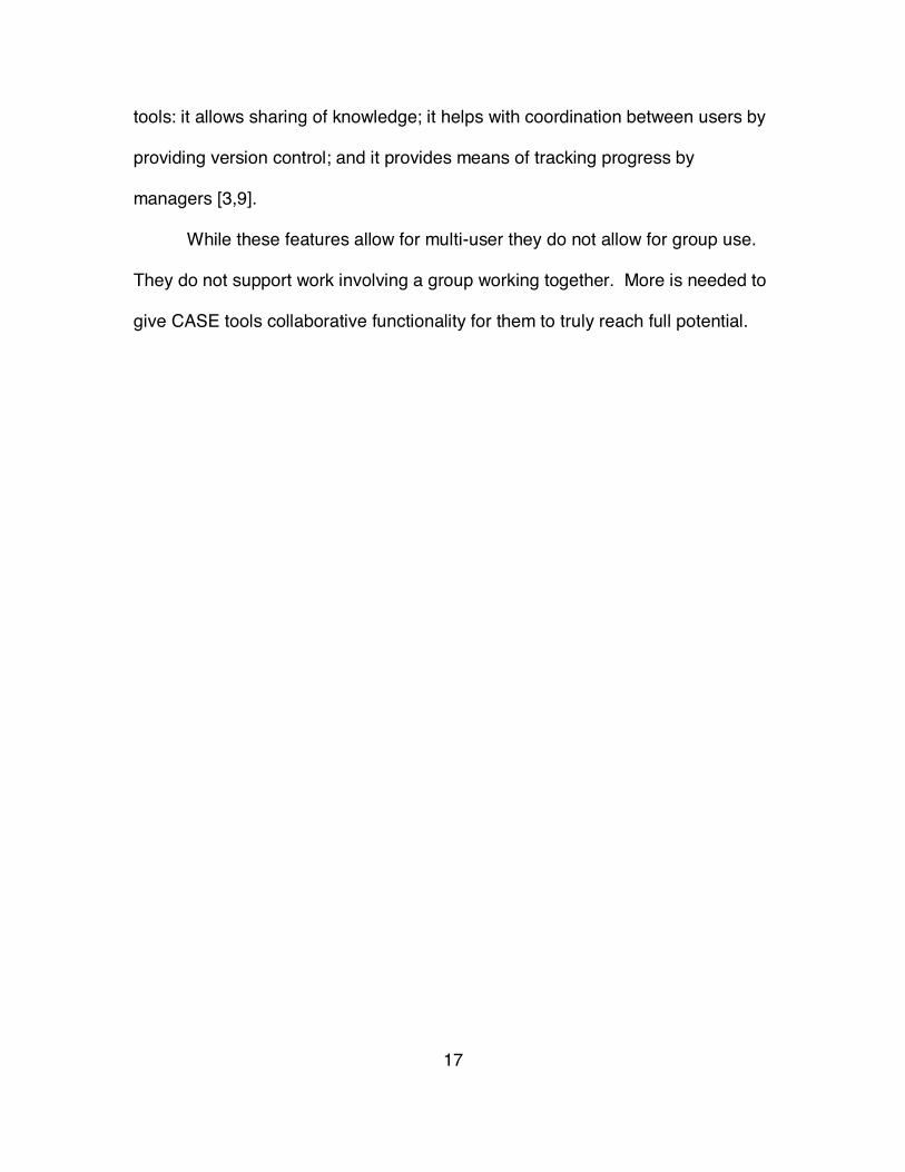
Figure 3 Members List
4.4.4 Members Class
The Members class shows all the members of the group who are working on the
collaboration. People who are online are displayed at the top and people who
are offline are on the bottom (see Figure 3). If a group member switches from
online to offline or vice-versa then that group member would be moved to the
appropriate area.

25
4.4.5 Properties Class
The Properties class provides the functionality to view and change the
information contained at each node (see Figure 4). Its main component is a
JTabbedPane, which allows the user to select which type of property they wish to
view or change.
This window allows the user access to the information stored in each
node.
Figure 4 Properties
4.4.6 LvNodeRenderer Class
The LvNodeRenderer class extends the DefaultTreeCellRenderer and is
used by the DefaultTreeModel to customize how each node is drawn. Each
26
LvNode contains an icon. This icon is changed when a new node is added to
that node or when the type is changed through the Properties class. The
LvNodeRenderer makes sure that the new node icon is displayed in the tree.

27
Chapter 5 The Collaboration Coordinator
The Collaboration Coordinator (CC) keeps the LvEditors synchronized with
one another so that all clients can see and manipulate the collaboration. The
CC is written in Java and uses RMI to pass information between the CC Server
and the LvEditor(s).
5.1 RMI
Remote Method Invocation (RMI) is Java’s method for building distributed
applications. RMI facilitates object function calls between Java Virtual Machines
(JVMs). JVMs can be located on separate computers, but one JVM can invoke
methods belonging to an object stored in another JVM. Methods can even pass
objects that a foreign virtual machine has never encountered before, allowing
dynamic loading of new classes as required [11].
By providing a way to call methods on objects on other systems, RMI
provides a higher level of abstraction than socket based programming, although
sockets are used under the covers. This higher level of abstraction makes
network programming less tedious and provides the developer with a relatively
easy way to develop powerful and useful client/server applications [12].
5.1.1 Remote Objects
A RMI application is made up of interfaces and classes. The interfaces define
methods and the classes implement those methods and possibly other methods
as well. Some objects have methods that can be called across JVMs, they are

28
called remote objects. An object becomes remote if its implementation contains
a remote interface, which has the following characteristics:
• A remote interface extends the interface java.rmi.Remote.
• Each method of the interface declares java.rmi.RemoteException in its
throws clause, in addition to any application-specific exceptions [13].
Remote objects are differently than local objects by RMI when they are
passed between JVMs. Instead of passing a copy of the remote object to the
receiving JVM, RMI passes a remote stub for a remote object. The stub acts as
the local representative for the remote object and basically is, to the caller, the
remote reference. The caller invokes a method on the local stub, which is
responsible for carrying out the method call on the remote object.
A stub for a remote object implements the same set of remote interfaces that
the remote object implements. This means that a stub may be casted to any
interface that the remote object implements, but only methods defined in a
remote interface are available to be called in the receiving JVM [13].
5.1.2 Creating Distributed Applications Using RMI
There are three parts to creating a distributed application described in Sun’s Java
tutorial [13]:
• Defining the remote interfaces: A remote interface specifies the methods
that can be invoked remotely by a client. Part of the design of such interfaces
is the determination of any local objects that will be used as parameters and
return values for these methods; if any of these interfaces or classes do not

29
yet exist, you need to define them as well.
• Implementing the remote objects: Remote objects must implement one or
more remote interfaces. The remote object class may include
implementations of other interfaces (either local or remote) and other
methods (which are available only locally). If any local classes are to be used
as parameters or return values to any of these methods, they must be
implemented as well.
• Implementing the clients: Clients that use remote objects can be
implemented at any time after the remote interfaces are defined, including
after the remote objects have been deployed [13].
5.1.3 Compiling and Running the Application
There are three steps to getting an RMI application up and running.
Compile Sources and
Generate Stubs
First use javac compiler to compile the source files.
Then use the rmic compiler to create stubs for the
remote objects.
Make Classes
Accessible
Make everything that needs to be downloaded to
clients--accessible via a Web server.
Starting the Application Starting the application includes running the RMI
remote object registry (rmiregistry), the server, and
the client [13].
30
5.2 The CCServer
The Collaboration Coordinator is what keeps all LvEditor(s) synchronized
so that they all see the same view of the collaboration. It is made up five classes
as follows:
CCServerIntf Defines the methods that CCServerImpl will implement.
CCServerImpl Implements methods that the client needs and data members
and methods that the server needs to perform its job.
CCServer Creates an instance of CCServerImpl and binds the object to
the rmiregistry.
CCClientIntf Defines the methods that DynamicTree will implement.
DynamicTree Implements methods that the server needs as well the
functionality necessary to create and change the tree.
5.2.1 CCServerIntf and CCClientIntf Interfaces
The CCServerIntf and the CCClientIntf are the remote interfaces that
define the methods that the client and server will use to make changes to the
collaboration and to communicate with one another. Both are defined below in
an abbreviated form for simplicity as follows:
public interface CCServerIntf extends Remote {
int addClient(ClientFunctions cf) throws RemoteException;
public void addNode(String path, LvNode ln) throws
RemoteException;
// Other Methods ...

31
}
public interface CCClientIntf extends Remote {
public void copyTree(JTree copyTree) throws RemoteException;
public void addNode(String path, LvNode ln) throws
RemoteException;
// Other Methods ...
}
5.2.2 The CCServer
The CCServer creates an instance of CCServerImpl and binds the object
to the rmiregistry; it follows in its entirety:
import java.net.*;
import java.rmi.*;
public class CCServer {
public static void main(String args[]){
try{
CCServerImpl CCServerImpl = new CCServerImpl();
Naming.rebind("CCServer", CCServerImpl);
}
catch(Exception e){
System.out.println("Exception: " +e);
}
}
}
32
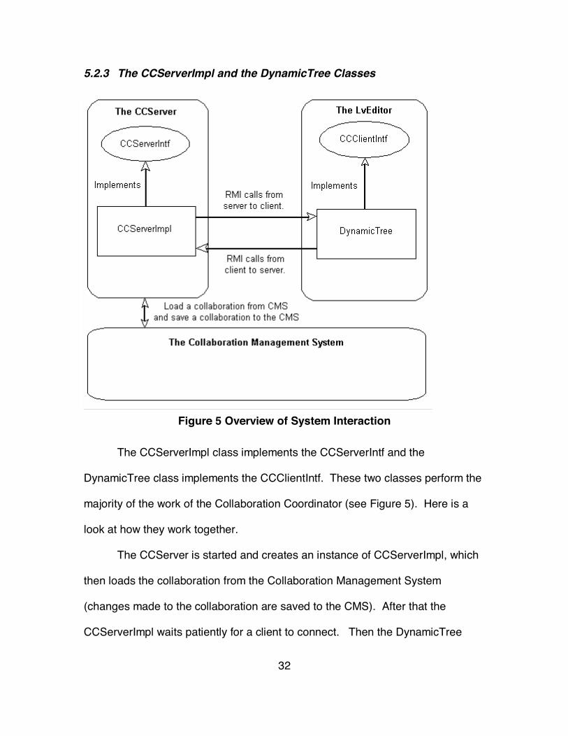
5.2.3 The CCServerImpl and the DynamicTree Classes
Figure 5 Overview of System Interaction
The CCServerImpl class implements the CCServerIntf and the
DynamicTree class implements the CCClientIntf. These two classes perform the
majority of the work of the Collaboration Coordinator (see Figure 5). Here is a
look at how they work together.
The CCServer is started and creates an instance of CCServerImpl, which
then loads the collaboration from the Collaboration Management System
(changes made to the collaboration are saved to the CMS). After that the
CCServerImpl waits patiently for a client to connect. Then the DynamicTree

33
finds (it uses the loopback address for easy testing) and connects to the
CCServerImpl, shown here:
try{
UnicastRemoteObject.exportObject(this);
String CCServerURL = "rmi://" + "127.0.0.1" + "/CCServer";
CCServerIntf =
(CCServerIntf)Naming.lookup(CCServerURL);
i = CCServerIntf.addClient(this);
}
catch(Exception e){
System.out.println("Exception: " + e);
}
It is important to notice that the DynamicTree is in effect sending “itself” to the
server by calling the CCServerImpl method addClient which is:
public synchronized int addClient(CCClientIntf cf) throws
RemoteException{
// fClients is a vector which contains all of the clients
fClients.addElement(cf);
return clientNumber++;
}
This allows the server to loop through fClients and call each client method.
This extremely useful feature lets the server update all the clients whenever a
change is made to the collaboration. When a client connects to the server, it is
sent a copy of the collaboration by the server, which makes a call to the client’s
copyTree method and passes the collaboration.

34
If a client wants to add a node to the collaboration the CC would work as
follows:
1. A user clicks a node and the add button on the LvEditor.
2. Then a call is made to the server method addNode, which is passed the tree
path as a string of node names and a LvNode.
3. The server adds the node to the server’s copy of the collaboration.
4. Then the server loops through the fClients vector and tells each client to do
add the node to the collaboration.
These same steps are followed anytime a client makes a change to the
collaboration.

35
Chapter 6 Conclusion
6.1 Future Work
Although the LvEditor and CCServer are complete, there is still much more
to be done on CSEE. Once the rest of CSEE has been completed, LvEditor and
CCServer will have to be integrated into it to make the CSEE complete. There is
also the possibility of adding more functionality to the LvEditor, such as adding
mechanisms for security to certain parts of the collaboration so that only certain
selected group members would have access to any particular part of the
collaboration. It would also be wise to do user testing on the LvEditor to see how
well it fills a group’s needs.
6.2 Summary
CSEE is a system to aid groups in working on a collaboration, and the
LvEditor and CCServer are integral parts of this system. The LvEditor gives
each user a method of viewing a collaboration and the means to make changes
to the collaboration. The CCServer is what makes sure all users see the same
view of a collaboration and makes sure that each client is updated when there is
a change made to the collaboration. People will be able to run the system on
any system the supports the JVM. By doing this CSEE will be available to aid
groups on any type of machine that they have. Once completed CSEE should
prove to be a truly useful tool to help groups.
36
References
[1] Ellis, C. A., S. J. Gibbs, and G. L. Rein, "Groupware: Some Issues andExperiences," Communications of the ACM, Vol. 34, No. 1 (January, 1991a),pp. 38-58.
[2] IEEE Standards Collection: Software Engineer, IEEE Standard 610.12-1990,IEEE, 1993
[3] Pressman, Rogers S., Software Engineering A Practitioner’s ApproachMcGraw-Hill, 1997
[4] Fouss, Jonathan D, “Proposal for a Collaborative Software EngineeringEnvironment”, Dissertation proposal presented to Dr. Chang 2000.
[5] Dollar, Timothy W., Ensuring Document Security, User Coordination, andMultimedia Synchronization in a Prototype Groupware Suite, Dissertation,June 1997.
[6] Grudin, Jonathan, “CSCW: History and Focus”, Communications of the ACM.Vol. 37, No. 1, pp. 92-105.
[7] Ellis, C A, S J Gibbs, and G L Rein, “Groupware: Some Issues andExperiences”, Readings in Groupware and Computer-Supported CooperativeWork, Morgan Kaufmann Publishers, Inc., San Mateo, CA, 1993, pp.9-28.
[8] Sharples, M, J S Goodlet, E E Beck, C C Wood, S M Easterbrook, and LPlowman, “Research Issues in the Study of Computer SupportedCollaborative Writing”, Computer Supported Collaborative Writing, Springer-Verlag, Germany, 1993, pp. 9-28.
[9] Kolland, Markus, "Distributed System Support for Consistency of SharedInformation in CSCW (Extended Abstract)," Workshop on DistributedSystems, Multimedia, and Infrastructure, ACM Conference on Computer-Supported Cooperative Work, Oct. 22, 1994.
[10] Drye, Stephen C., Wake William C., Java Foundation Classes SwingReferences, Manning, 1999.
[11] Reilly, David, “Introduction to Java RMI”,http://www.javacoffeebreak.com/articles/javarmi/javarmi.html, 2000.
[12] Litwak, Kenneth, Pure Java 2, Sams Publishing, 1999.[13] ____, “An Overview of RMI Applications”,
http://java.sun.com/docs/books/tutorial/rmi/overview.html, 2000.