Graphical symbols for diagrams - OILWEB · BRITISH STANDARD BS EN 60617-6:1996 IEC 617-6: 1996...
46
BRITISH STANDARD BS EN 60617-6:1996 IEC 617-6: 1996 Graphical symbols for diagrams — Part 6: Production and conversion of electrical energy The European Standard EN 60617-6:1996 has the status of a British Standard ICS 01.080.30; 29.020
Transcript of Graphical symbols for diagrams - OILWEB · BRITISH STANDARD BS EN 60617-6:1996 IEC 617-6: 1996...
BRITISH STANDARD BS EN 60617-6:1996IEC 617-6:1996
Graphical symbols for diagrams —
Part 6: Production and conversion of electrical energy
The European Standard EN 60617-6:1996 has the status of a British Standard
ICS 01.080.30; 29.020

BS EN 60617-6:1996
This British Standard, having been prepared under the direction of the Electrotechnical Sector Board, was published under the authority of the Standards Board and comes into effect on 15 December 1996
© BSI 10-1998
The following BSI references relate to the work on this standard:Committee reference GEL/3 Draft for comment 92/28836 DC
ISBN 0 580 26760 1
Committees responsible for this British Standard
The preparation of this British Standard was entrusted to Technical Committee GEL/3, Documentation and graphical symbols, upon which the following bodies were represented:
British Photographic AssociationConsumer Policy Committee of BSIFederation of the Electronics IndustryGAMBICA (BEAMA Ltd.)Transmission and Distribution Association (BEAMA Ltd.)
Amendments issued since publication
Amd. No. Date Comments

BS EN 60617-6:1996
© BSI 10-1998 i
Contents
PageCommittees responsible Inside front coverNational foreword ii
Foreword 2Text of EN 60617-6:1996 3

BS EN 60617-6:1996
ii © BSI 10-1998
National foreword
This British Standard has been prepared by Technical Committee GEL/3. It is the English language version of EN 60617-6:1996, Graphical symbols for diagrams Part 6: Production and conversion of electrical energy published by the European Committee for Electrotechnical Standardization (CENELEC). It is identical with IEC 617-6:1996 published by the International Electrotechnical Commission (IEC).This British Standard replaces BS 3939-6:1985 which is withdrawn.NOTE The French language version of the alphabetic index has not been included.
A British Standard does not purport to include all the necessary provisions of a contract. Users of British Standards are responsible for their correct application.
Compliance with a British Standard does not of itself confer immunity from legal obligations.
Summary of pagesThis document comprises a front cover, an inside front cover, pages i and ii, the EN title page, pages 2 to 41 and a back cover.This standard has been updated (see copyright date) and may have had amendments incorporated. This will be indicated in the amendment table on the inside front cover.

EUROPEAN STANDARD
NORME EUROPÉENNE
EUROPÄISCHE NORM
EN 60617-6
June 1996
ICS 01.080.30
Descriptors: Electric conversion, production of electrical energy, electric diagram, electrical symbol
English version
Graphical symbols for diagramsPart 6: Production and conversion of electrical energy
(IEC 617-6:1996)
Symboles graphiques pour schémas Partie 6: Production, transformation et conversion de l’énergie électrique (CEI 617-6:1996)
Graphische Symbole für Schaltpläne Teil 6: Schaltzeichen für die Erzeugung und Umwandlung elektrischer Energie (IEC 617-6:1996)
This European Standard was approved by CENELEC on 1996-03-05.CENELEC members are bound to comply with the CEN/CENELEC InternalRegulations which stipulate the conditions for giving this European Standardthe status of a national standard without any alteration.Up-to-date lists and bibliographical references concerning such nationalstandards may be obtained on application to the Central Secretariat or to anyCENELEC member.This European Standard exists in three official versions (English, French,German). A version in any other language made by translation under theresponsibility of a CENELEC member into its own language and notified to theCentral Secretariat has the same status as the official versions.CENELEC members are the national electrotechnical committees of Austria,Belgium, Denmark, Finland, France, Germany, Greece, Iceland, Ireland, Italy,Luxembourg, Netherlands, Norway, Portugal, Spain, Sweden, Switzerland andUnited Kingdom.
CENELEC European Committee for Electrotechnical Standardization
Comité Européen de Normalisation Electrotechnique Europäisches Komitee für Elektrotechnische Normung
Central Secretariat: rue de Stassart 35, B-1050 Brussels
© 1996 Copyright reserved to CENELEC membersRef. No. EN 60617-6:1996 E

EN 60617-6:1996
© BSI 10-19982
Foreword
The text of document 3A/384/FDIS, future edition 2 of IEC 617-6, prepared by SC 3A, Graphical symbols for diagrams, of IEC TC 3, Documentation and graphical symbols, was submitted to the IEC-CENELEC parallel vote and was approved by CENELEC as EN 60617-6 on 1996-03-05.The following dates were fixed:
Contents
PageIntroduction 3Chapter I: Qualifying symbols for winding interconnectionsSection 1 Separate windings 4Section 2 Internally connected windings 5Chapter II: MachinesSection 3 Elements of machines 7Section 4 Types of machines 8Section 5 Examples of direct current machines 9Section 6 Examples of alternating current commutator machines 10Section 7 Examples of synchronous machines 11Section 8 Examples of induction type (asynchronous) machines 13Chapter III: Transformers and reactorsSection 9 General symbols for transformers and reactors 16Section 10 Examples of transformers with separate windings 19Section 11 Examples of auto-transformers 25Section 12 Examples of induction regulators 26Section 13 Examples of measuring transformers and pulse transformers 27Chapter IV: Power convertersSection 14 Block symbols for power converters 31Chapter V: Primary and secondary cells and batteriesSection 15 Primary and secondary cells 32Chapter VI: Power generatorsSection16 General symbol for non-rotarypower generators 33Section 17 Heat sources 33Section 18 Examples of power generators 34Section 19 Closed-loop controllers 36Annex A (informative) Older symbols 37Annex B (informative) English alphabetic index 38
– latest date by which the EN has to be implemented at national level by publication of an identical national standard or by endorsement (dop) 1997-02-01
– latest date by which the national standards conflicting with the EN have to be withdrawn (dow) 1997-02-01

EN 60617-6:1996
© BSI 10-1998 3
IntroductionThis part of IEC 617 forms an element of a series which deals with graphical symbols for diagrams.The series consists of the following parts:
— Part 1: General information, general index. Cross-reference tables;— Part 2: Symbol elements, qualifying symbols and other symbols having general application;— Part 3: Conductors and connecting devices;— Part 4: Basic passive components;— Part 5: Semiconductors and electron tubes;— Part 6: Production and conversion of electrical energy;— Part 7: Switchgear, controlgear and protective devices;— Part 8: Measuring instruments, lamps and signalling devices;— Part 9: Telecommunications: Switching and peripheral equipment;— Part 10: Telecommunications: Transmission;— Part 11: Architectural and topographical installation plans and diagrams;— Part 12: Binary logic elements;— Part 13: Analogue elements.
The scope and the normative references for this series are given in IEC 617-1.Symbols have been designed in accordance with requirements given in the future ISO 11714-11). The module size M = 2,5 mm has been used. For better readability smaller symbols in this standard have been enlarged to double size and are marked “200 %” in the symbol column. To save space larger symbols have been reduced to half size and are marked “50 %” in the symbol column. In accordance with the future ISO 11714-1, clause 7, symbol dimensions (for instance height) may be modified in order to make space for a greater number of terminals or for other layout requirements. In all cases, whether the size is enlarged or reduced, or dimensions modified, the thickness of the original line should be maintained without scaling.
The symbols in this standard are laid out in such a way that the distance between connecting lines is a multiple of a certain modulus. Modulus 2M has been chosen to provide enough space for the required terminal designation. The symbols have been drawn to a size convenient for comprehension, using consistently the same grid in the representation of all symbols.All symbols are designed within a grid in a computer-aided draughting system. The grid which was used has been reproduced in the background of the symbols.The older symbols which were included in appendix A of the first edition of IEC 617-6 for a transitional period, are no longer part of this second edition, as they will definitely be withdrawn from use.The indexes in Annex B and C include an alphabetic list of symbol names and their corresponding number. The symbol names are based on the description of the symbols of this part. A general index including an alphabetic list of symbols of all parts is given in IEC 617-1.
1) At present, at the stage of Draft International Standard (document 3/563/DIS).
EN
60617-6:1996
4©
BS
I 10-1998
Chapitre I: Symboles distinctifs pour l’interconnexion des enroulements
Chapter I: Qualifying symbols for winding interconnections
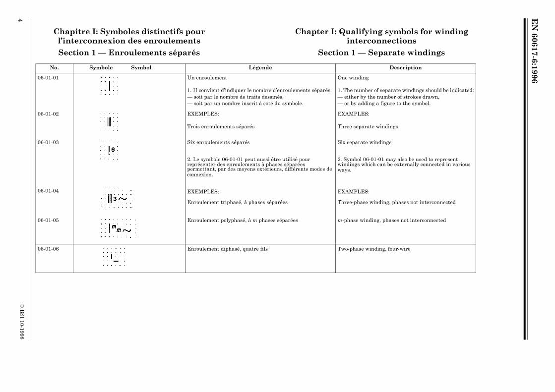
Section 1 — Enroulements séparés Section 1 — Separate windings
No. Symbole Symbol Légende Description
06-01-01 Un enroulement One winding
1. II convient d’indiquer le nombre d’enroulements séparés:— soit par le nombre de traits dessinés,— soit par un nombre inscrit à coté du symbole.
1. The number of separate windings should be indicated:— either by the number of strokes drawn,— or by adding a figure to the symbol.
06-01-02 EXEMPLES: EXAMPLES:
Trois enroulements séparés Three separate windings
06-01-03 Six enroulements séparés Six separate windings
2. Le symbole 06-01-01 peut aussi être utilisé pour représenter des enroulements à phases séparées permettant, par des moyens extérieurs, différents modes de connexion.
2. Symbol 06-01-01 may also be used to represent windings which can be externally connected in various ways.
06-01-04 EXEMPLES: EXAMPLES:
Enroulement triphasé, à phases séparées Three-phase winding, phases not interconnected
06-01-05 Enroulement polyphasé, à m phases séparées m-phase winding, phases not interconnected
06-01-06 Enroulement diphasé, quatre fils Two-phase winding, four-wire

EN
60617-6:1996
© B
SI 10-1998
5
Section 2 — Enroulements connectés intérieurement
Section 2 — Internally connected windings
2.1 Le mode de connexion des enroulements de transformateurs peut également être indiqué par des codes. Voir la CEI 76: Transformateurs de puissance.
2.1 The method of connecting transformer windings may also be indicated by codes. See IEC Publication 76: Power Transformers.
No. Symbole Symbol Légende Description
06-02-01 Enroulement diphasé Two-phase winding
06-02-02 Enroulement triphasé partiel, en V (60º) Three-phase winding, V (60º)
06-02-03 Enroulement tétraphasé, avec neutre sorti Four-phase winding with neutral brought out
06-02-04 Enroulement triphasé, en T Three-phase winding, T
06-02-05 Enroulement triphasé, en triangle Three-phase winding, delta
Ce symbols peut aussi être utilisé pour représenter des enroulements multiphasés connectés en polygone, en précisant par un chiffre le nombre de phases.
This symbol may be used to symbolize a multiphase polygon connection of windings by adding a figure to denote the number of phases.
06-02-06 Enroulement triphasé, en triangle ouvert Three-phase winding, open delta
06-02-07 Enroulement triphasé, en étoile Three-phase winding, star
Ce symbole peut aussi être utilisé pour représenter des enroulements multiphasés connectés en étoile, en précisant par un chiffre le nombre de phases.
This symbol may be used to symbolize a multiphase star connection of windings by adding a figure to denote the number of phases.
06-02-08 Enroulement triphasé, en étoile, avec neutre sorti Three-phase winding, star, with neutral brought out

EN
60617-6:1996
6©
BS
I 10-1998
06-02-09 Enroulement triphasé, en zigzag Three-phase winding, zigzag or interconnected star
06-02-10 Enroulement hexaphasé, en double triangle Six-phase winding, double delta
06-02-11 Enroulement hexaphasé, en polygone Six-phase winding, polygon
06-02-12 Enroulement hexaphasé, en étoile Six-phase winding, star
06-02-13 Enroulement hexaphasé, en double zigzag, avec neutre sorti Six-phase winding, fork with neutral brought out
No. Symbole Symbol Légende Description
EN
60617-6:1996
© B
SI 10-1998
7
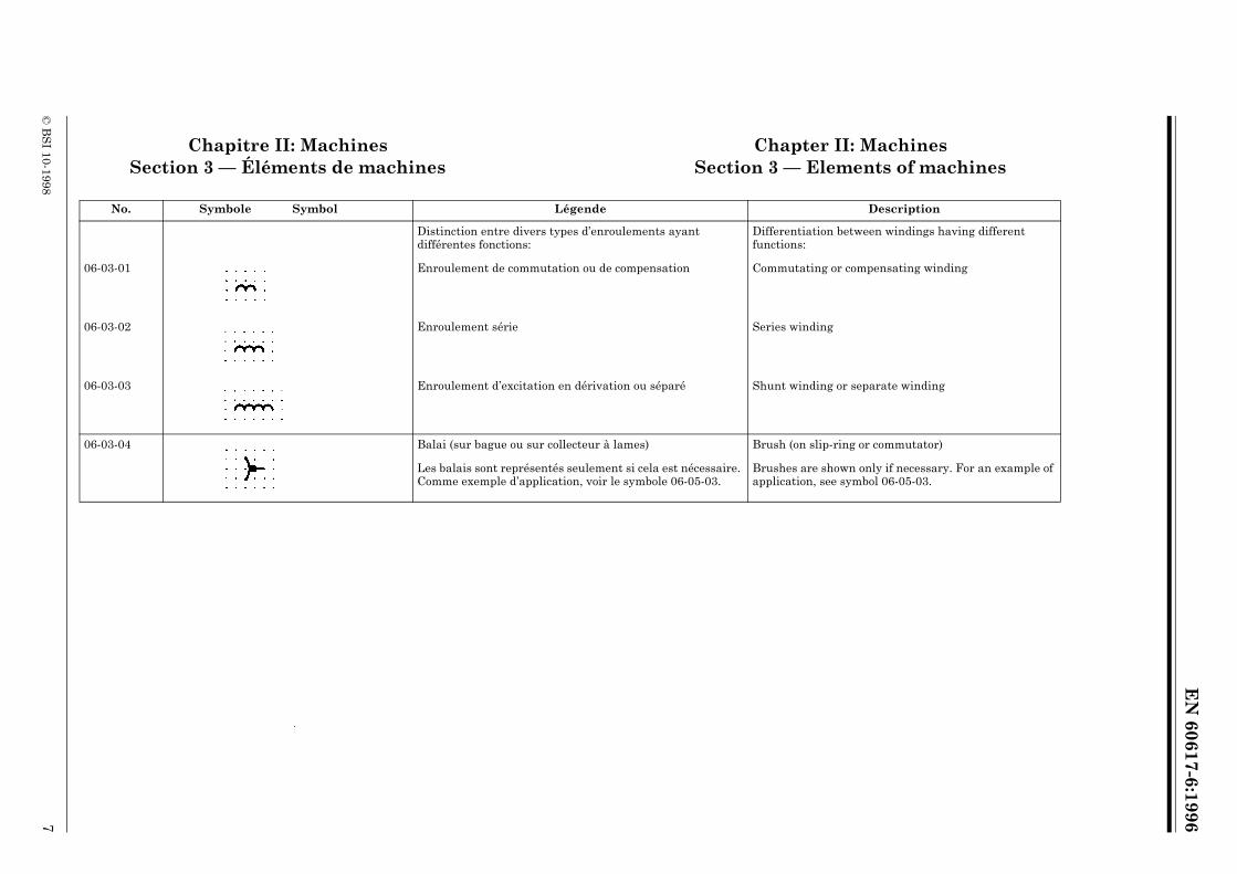
Chapitre II: Machines Chapter II: MachinesSection 3 — Éléments de machines Section 3 — Elements of machines
No. Symbole Symbol Légende Description
Distinction entre divers types d’enroulements ayant différentes fonctions:
Differentiation between windings having different functions:
06-03-01 Enroulement de commutation ou de compensation Commutating or compensating winding
06-03-02 Enroulement série Series winding
06-03-03 Enroulement d’excitation en dérivation ou séparé Shunt winding or separate winding
06-03-04 Balai (sur bague ou sur collecteur à lames) Brush (on slip-ring or commutator)
Les balais sont représentés seulement si cela est nécessaire. Comme exemple d’application, voir le symbole 06-05-03.
Brushes are shown only if necessary. For an example of application, see symbol 06-05-03.
EN
60617-6:1996
8©
BS
I 10-1998
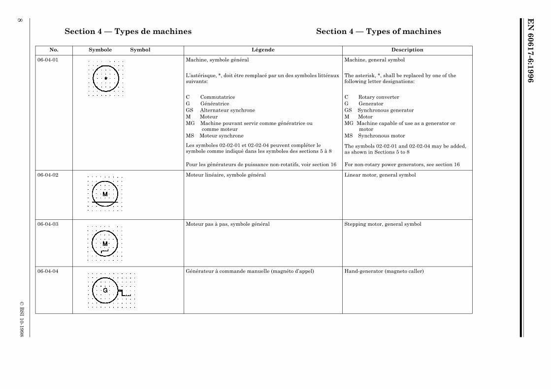
Section 4 — Types de machines Section 4 — Types of machines
No. Symbole Symbol Légende Description
06-04-01 Machine, symbole général Machine, general symbol
L’astérisque, *, doit être remplacé par un des symboles littéraux suivants:
The asterisk, *, shall be replaced by one of the following letter designations:
C CommutatriceG GénératriceGS Alternateur synchroneM MoteurMG Machine pouvant servir comme génératrice ou
comme moteurMS Moteur synchrone
C Rotary converterG GeneratorGS Synchronous generatorM MotorMG Machine capable of use as a generator or
motorMS Synchronous motor
Les symboles 02-02-01 et 02-02-04 peuvent compléter le symbole comme indiqué dans les symboles des sections 5 à 8
The symbols 02-02-01 and 02-02-04 may be added, as shown in Sections 5 to 8
Pour les générateurs de puissance non-rotatifs, voir section 16 For non-rotary power generators, see section 16
06-04-02 Moteur linéaire, symbole général Linear motor, general symbol
06-04-03 Moteur pas à pas, symbole général Stepping motor, general symbol
06-04-04 Générateur à commande manuelle (magnéto d’appel) Hand-generator (magneto caller)

EN
60617-6:1996
© B
SI 10-1998
9
Section 5 — Exemples de machines à courant continu
Section 5 — Examples of direct current machines
No. Symbole Symbol Légende Description
06-05-01 Moteur série, DC Series motor, DC
06-05-02 Moteur shunt (à excitation en dérivation), DC Shunt motor, DC
06-05-03 Génératrice DC à excitation composée à courte dérivation, représentée avec bomes et balais
Generator, DC, compound excited (short shunt), shown with terminals and brushes
06-05-04 Convertisseur rotatif, DC/DC avec excitation commune par aimant permanent
Rotary converter, DC/DC with common permanent magnet field
06-05-05 Convertisseur rotatif, DC/DC avec enroulement d’excitation commun
Rotary converter, DC/DC with common exitation winding

EN
60617-6:1996
10©
BS
I 10-1998
Section 6 — Exemples de machines à courant alternatif à collecteur
Section 6 — Examples of alternating current commutator machines
No. Symbole Symbol Légende Description
06-06-01 Moteur série, monophasé Series motor, single-phase
06-06-02 Moteur à répulsion, monophasé Repulsion motor, single-phase
06-06-03 Moteur série, triphasé Series motor, three-phase

EN
60617-6:1996
© B
SI 10-1998
11
Section 7 — Exemples de machines synchrones
Section 7 — Examples of synchronous machines
No. Symbole Symbol Légende Description
06-07-01 Alternateur synchrone à aimant permanent, triphasé Synchronous generator, three-phase with permanent magnet
06-07-02 Moteur synchrone monophasé Synchronous motor, single-phase
06-07-03 Alternateur synchrone, triphasé à induit monté en étoile, neutre sorti
Synchronous generator, three-phase, star connected, neutral brought out
06-07-04 Alternateur synchrone triphasé, à deux extrémités sorties pour chaque enroulement de phase
Synchronous generator, three-phase, both ends of each phase winding brought out

EN
60617-6:1996
12©
BS
I 10-1998
06-07-05 Commutatrice triphasée à excitation en dérivation Synchronous rotary converter, three-phase, shunt- excited
No. Symbole Symbol Légende Description

EN
60617-6:1996
© B
SI 10-1998
13
Section 8 — Exemples de machines à induction (Asynchrones)
Section 8 — Examples of induction type (Asynchronous) machines
8.1 II convient que le symbole général pour une machine (06-04-01) soit utilisé pour représenter une machine asynchrone dont le rotor n’a pas de connexions extérieures, par exemple pour un moteur à rotor en court-circuit. II convient de dessiner un cercle intérieur, représentant le rotor si celui-ci comporte des connexions extérieures, voir par exemple le symbole 06-08-03.
8.1 The general symbol for a machine (06-04-01) should be used to represent an asynchronous machine, if no external connections to the rotor exist, for example in a squirrel cage motor. An inner circle, representing the rotor, should be shown in those cases where external connections to the rotor exist, see for example symbol 06-08-03.
No. Symbole Symbol Légende Description
06-08-01 Moteur asynchrone triphasé, à rotor en court-circuit Induction motor, three-phase, squirrel cage
06-08-02 Moteur asynchrone monophasé, à rotor en court-circuit, enroulement de phase auxiliaire à extrémités sorties
Induction motor, single-phase, squirrel-cage, ends of split-phase winding brought out
06-08-03 Moteur asynchrone triphasé à rotor à bagues Induction motor, three-phase, with wound rotor

EN
60617-6:1996
14©
BS
I 10-1998
06-08-04 Moteur asynchrone, triphasé, à stator monté en étoile, avec démarreur automatique incorporé
Induction motor, three-phase, star-connected, with built-in automatic starter
06-08-05 Moteur linéaire asynchrone triphasé à déplacement dans un seul sens
Linear induction motor, three-phase, movement only in one direction
No. Symbole Symbol Légende Description

EN
60617-6:1996
© B
SI 10-1998
15
Chapitre III: Transformateurs et inductances Chapter III: Transformers and reactors1 Deux formes de symboles sont données pour un même type de transformateur: 1 Two forms of symbols are shown for the same type of transformer:
— En forme 1: Chaque enroulement est représenté par un cercle. Cette utilisation est de préférence limitée à la représentation unifilaire. Les symboles des noyaux de transformateurs ne sont pas utilisés dans cette forme.
— Form 1 uses a circle to represent each winding. Its use is preferably restricted to single-line representation. Symbols for transformer cores are not used with this form.
— En forme 2: Chaque enroulement est représenté par le symbole 04-03-01. On peut différencier entre certains enroulements par le nombre de demi-cercles.
— Form 2 uses symbol 04-03-01 to represent each winding. The number of half-circles may be varied to differentiate between certain windings.
2 La note 2 du symboles 04-03-01 est applicable à la représentation du noyau d’un transformateur.
2 For the representation of transformer cores, see Note 2 with symbol 04-03-01.
3 Dans les symboles de transformateurs de courant ou d’impulsion, des traits droits peuvent être utilisés pour représenter des enroulements primaires. Voir section 13.
3 In the case of symbols for current and pulse transformers, straight lines, representing primary windings may be used with either form.See Section 13.
4 La CEI 375 donne une méthode permettant d’indiquer la correspondance entre les polarités instantanées des tensions de circuits électriques couplés. Comme exemple d’application, voir symbole 06-09-03.
4 IEC 375 gives a method of indicating the instantaneous voltage polarities of coupled electric circuits. For an example of application, see symbol 06-09-03.

EN
60617-6:1996
16©
BS
I 10-1998
Section 9 — Symboles généraux pour transformateurs et reactances
Section 9 — General symbols for transformers and reactors
No. Symbole Symbol Légende Description
06-09-01 Forme 1Form 1
Transformateur à deux enroulements Transformer with two windings
06-09-02 Forme 2Form 2
Les polarités instantanées des tensions peuvent être indiquées en forme 2 du symbole.
The instantaneous voltage polarities may be indicated in form 2 of the symbol.
06-09-03 Forme 2Form 2
EXEMPLE: EXAMPLE:
Transformateur à deux enroulements, figuré avec indicateurs de polarité instantanée des tensions
Transformer with two windings, shown with instantaneous voltage polarity indicators
Des courants instantanés entrant par les extrémités des enroulements marqués d’un point produisent des flux additifs
Instantaneous currents entering the marked ends of the windings produce aiding fluxes

EN
60617-6:1996
© B
SI 10-1998
17
06-09-04 Forme 1Form 1
Transformateur à trois enroulements Transformer with three windings
06-09-05 Forme 2Form 2
06-09-06 Forme 1Form 1
Autotransformateur Auto-transformer
06-09-07 Forme 2Form 2
06-09-08 Forme 1Form 1
Inductance Choke
Reactor
06-09-09 Forme 2Form 2
Utiliser is symbole 04-03-01
Use symbol 04-03-01
No. Symbole Symbol Légende Description

EN
60617-6:1996
18©
BS
I 10-1998
06-09-10 Forme 1Form 1
Transformateur de courant
Transformateur d’impulsion
Current transformer
Pulse transformer
06-09-11 Forme 2Form 2
No. Symbole Symbol Légende Description

EN
60617-6:1996
© B
SI 10-1998
19
Section 10 — Exemples de transformateurs à enroulements séparés
Section 10 — Examples of transformers with separate windings
No. Symbole Symbol Légende Description
06-10-01 Forme 1Form 1
Transformateur monophasé à deux enroulements avec écran
Single-phase transformer with two windings and screen
06-10-02 Forme 2Form 2
06-10-03 Forme 1Form 1
Transformateur à prise médiane sur un enroulement
Transformer with centre tapping on one winding
06-10-04 Forme 2Form 2

EN
60617-6:1996
20©
BS
I 10-1998
06-10-05 Forme 1Form 1
Transformateur à couplage réglable Transformer with variable coupling
06-10-06 Forme 2Form 2
06-10-07 Forme 1Form 1
Transformateur triphasé, couplage étoile-triangle
Three-phase transformer, connection star-delta
06-10-08 Forme 2Form 2
No. Symbole Symbol Légende Description

EN
60617-6:1996
© B
SI 10-1998
21
06-10-09 Forme 1Form 1
Transformateur triphasé à quatre prises, couplage: étoile-étoile
Chaque enroulement primaire est figuré avec quatre sorties disponibles s’ajoutant à celles des extrémités d’enroulement
Three-phase transformer with four tappings (taps), connection; star-star
Each primary winding is shown with four available connection points in addition to those at the winding-ends
06-10-10 Forme 2Form 2
06-10-11 Forme 1Form 1
Groupe de trois transformateurs monophasés, couplage étoile-triangle
Three-phase bank of single-phase transformers, connection star-delta
06-10-12 Forme 2Form 2
No. Symbole Symbol Légende Description
EN
60617-6:1996
22©
BS
I 10-1998
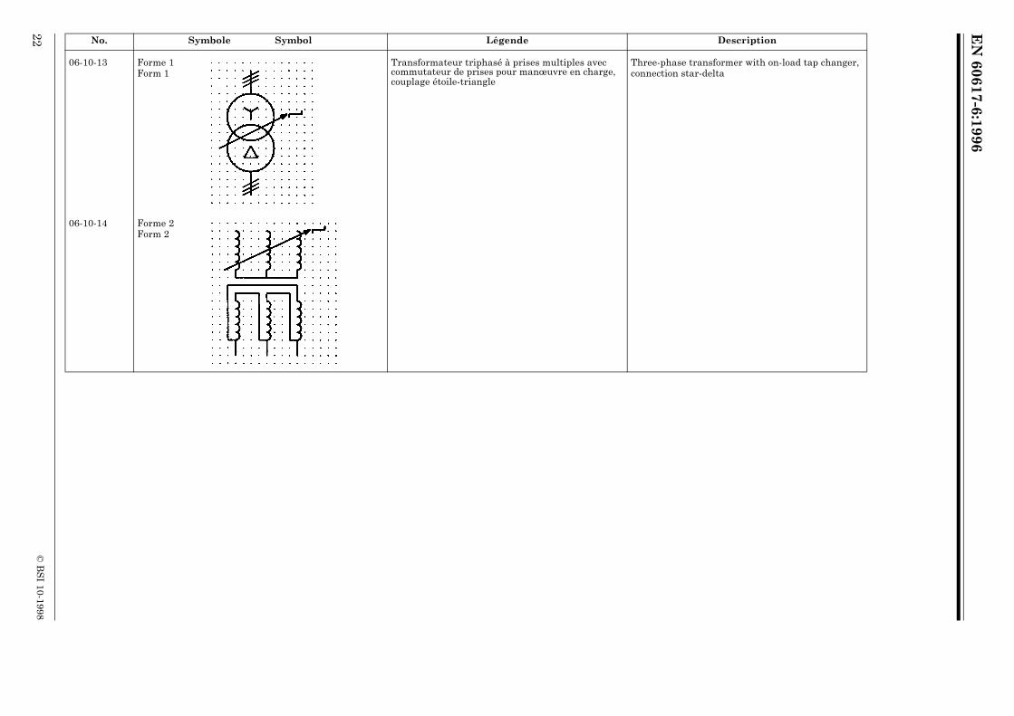
06-10-13 Forme 1Form 1
Transformateur triphasé à prises multiples avec commutateur de prises pour manœuvre en charge, couplage étoile-triangle
Three-phase transformer with on-load tap changer, connection star-delta
06-10-14 Forme 2Form 2
No. Symbole Symbol Légende Description

EN
60617-6:1996
© B
SI 10-1998
23
06-10-15 Forme 1Form 1
Transformateur triphasé, couplage étoile-zigzag avec neutre sorti
Three-phase transformer, connection star-zigzag with the neutral brought out
06-10-16 Forme 2Form 2
No. Symbole Symbol Légende Description
EN
60617-6:1996
24©
BS
I 10-1998
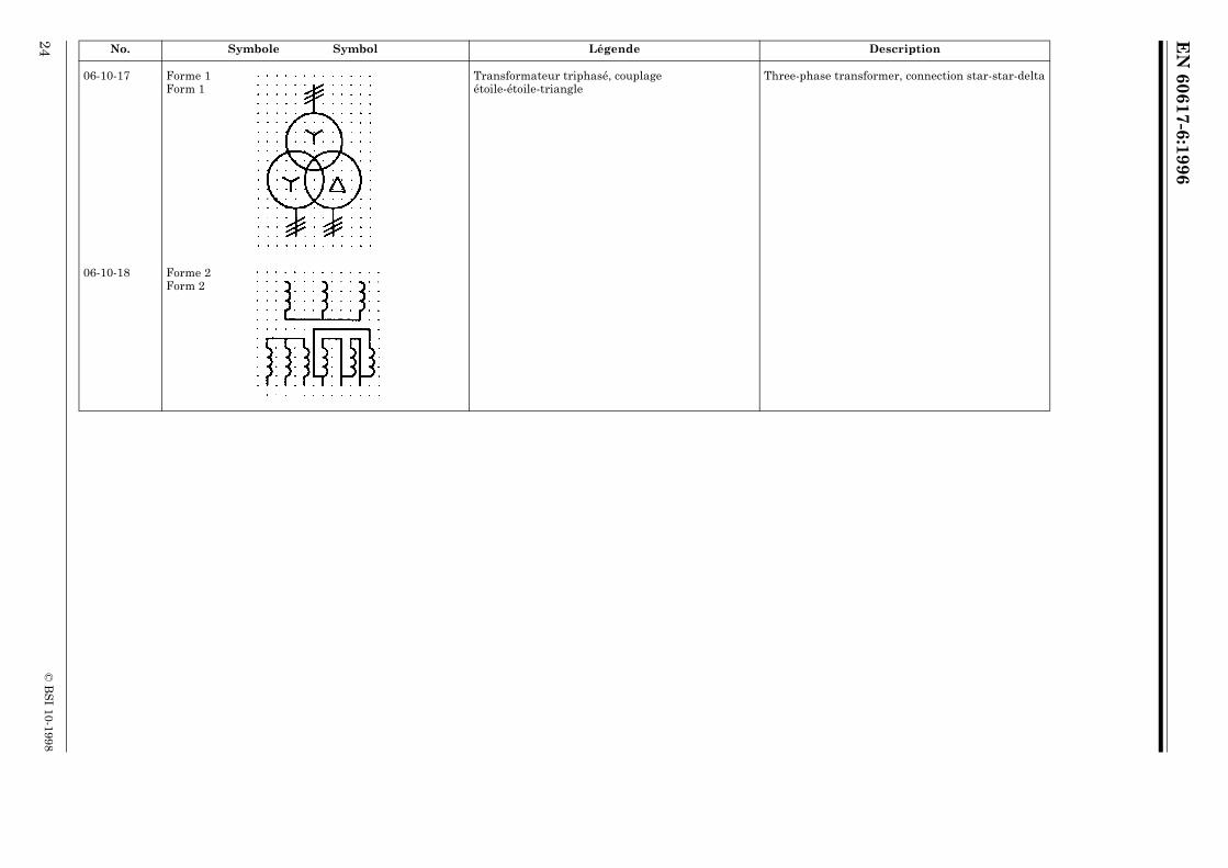
06-10-17 Forme 1Form 1
Transformateur triphasé, couplage étoile-étoile-triangle
Three-phase transformer, connection star-star-delta
06-10-18 Forme 2Form 2
No. Symbole Symbol Légende Description

EN
60617-6:1996
© B
SI 10-1998
25
Section 11 — Exemples d’autotransformateurs Section 11— Examples of auto-transformers
No. Symbole Symbol Légende Description
06-11-01 Forme 1Form 1
Autotransformateur, monophasé Auto-transformer, single-phase
06-11-02 Forme 2Form 2
06-11-03 Forme 1Form 1
Autotransformateur, triphasé, couplage étoile Auto-transformer, three-phase, connection star
06-11-04 Forme 2 Form 2

EN
60617-6:1996
26©
BS
I 10-1998
06-11-05 Forme 1Form 1
Autotransformateur, monophasé à réglage progressif de la tension
Auto-transformer, single-phase with voltage regulation
06-11-06 Forme 2Form 2
Section 12 — Exemples de régulateurs à induction
Section 12 — Examples of induction regulators
No. Symbole Symbol Légende Description
06-12-01 Forme 1Form 1
Régulateur à induction triphasé Three-phase induction regulator
06-12-02 Forme 2Form 2
No. Symbole Symbol Légende Description

EN
60617-6:1996
© B
SI 10-1998
27
Section 13 — Exemples de transformateurs de mesure et de transformateurs d’impulsion
Section 13 — Examples of measuring transformers and pulse transformers
13.1 Pour les transformateurs de mesure ou transformateurs d’impulsion utiliser le symbole apprôprié de la section 9 .
13.1 For measuring transformers and pulse transformers use the appropriate symbol from section 9.
No. Symbole Symbol Légende Description
06-13-01A Forme 1Form 1
Transformateur de tension Voltage transformer
06-13-01B Forme 2Form 2
06-13-02 Forme 1Form 1
Transformateur de courant à deux noyaux avec un enroulement secondaire sur chaque noyau.
Current transformer with two cores with one secondary winding on each core.
Les symboles des bornes dessinés à chaque extrémité du circuit primaire indiquent qu’il s’agit d’un appareil unique. Les symboles de bornes peuvent être omis si la désignation de l’appareil est indiquée.
The terminal symbols shown at each end of the primary circuit indicate that only a single device is represented. The terminal symbols may be omitted if terminal designations are used.
Dans la forme 2, les symboles des circuits magnétiques peuvent être omis.
In form 2, core symbols may be omitted.
06-13-03 Forme 2Form 2
EN
60617-6:1996
28©
BS
I 10-1998
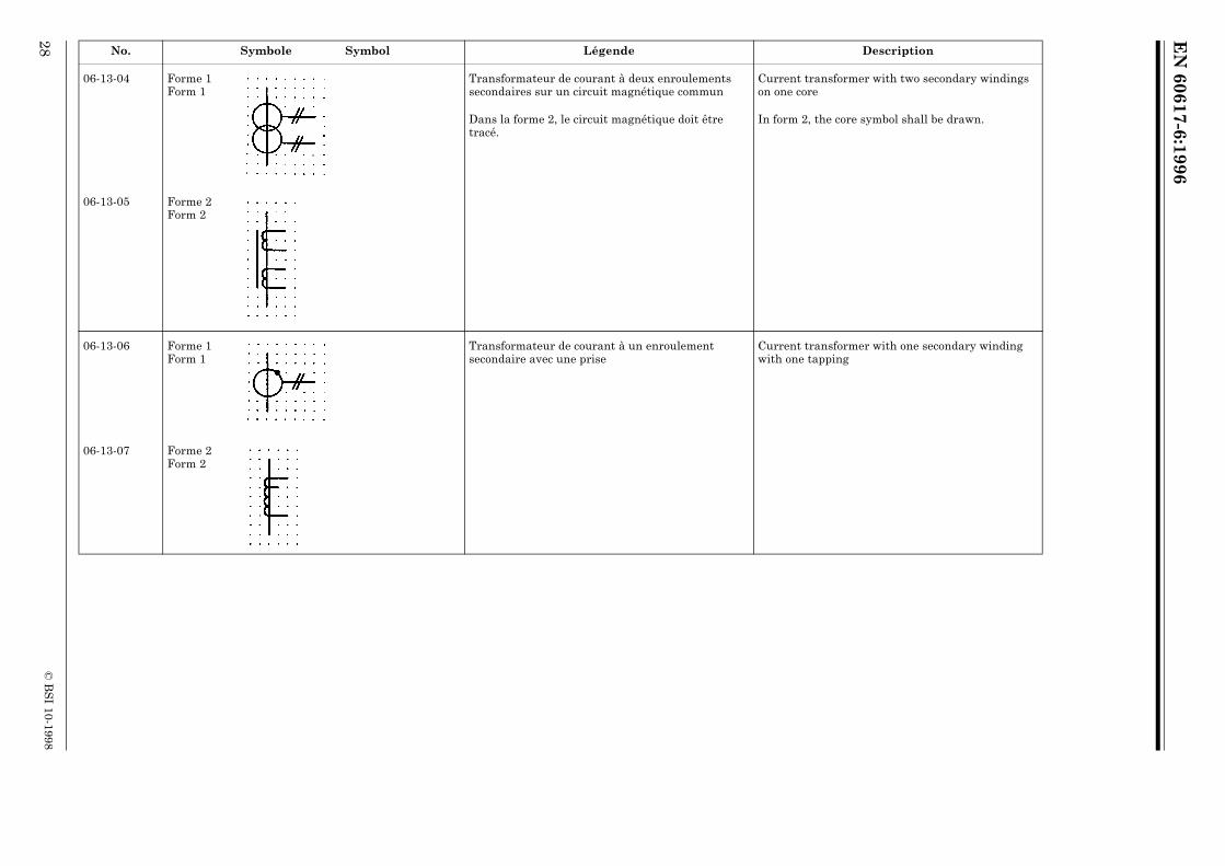
06-13-04 Forme 1Form 1
Transformateur de courant à deux enroulements secondaires sur un circuit magnétique commun
Current transformer with two secondary windings on one core
Dans la forme 2, le circuit magnétique doit être tracé.
In form 2, the core symbol shall be drawn.
06-13-05 Forme 2Form 2
06-13-06 Forme 1Form 1
Transformateur de courant à un enroulement secondaire avec une prise
Current transformer with one secondary winding with one tapping
06-13-07 Forme 2Form 2
No. Symbole Symbol Légende Description

EN
60617-6:1996
© B
SI 10-1998
29
06-13-08 Forme 1Form 1
Transformateur de courant avec cinq passages d’un conducteur servant comme bobine primaire Cette sorte de transformateur n’a pas de bobine primaire incorporée.
Current transformer with five passages of a conductor acting as a primary winding This kind of current transformer has no built-in primary winding.
06-13-09 Forme 2Form 2
06-13-10 Forme 1Form 1
Transformateur d’impulsion ou de courant avec trois conducteurs primaires traversants
Pulse or current transformer with three threaded primary conductors
06-13-11 Forme 2Form 2
No. Symbole Symbol Légende Description

EN
60617-6:1996
30©
BS
I 10-1998
06-13-12 Forme 1Form 1
Transformateur d’impulsion ou de courant avec deux enroulements secondaires sur le même noyau et neuf conducteurs primaires traversants
Pulse or current transformer with two secondary windings on the same core and nine threaded primary conductors
06-13-13 Forme 2Form 2
No. Symbole Symbol Légende Description

EN
60617-6:1996
© B
SI 10-1998
31
Chapitre IV: Convertisseurs de puissance Chapter IV: Power converters
Section 14 — Symboles fonctionnels pour convertisseurs de puissance
Section 14 — Block symbols for power converters
No. Symbole Symbol Légende Description
06-14-01 Convertisseur, symbole général Converter, general symbol
06-14-02 Convertisseur DC/DC DC/DC converter
06-14-03 Redresseur Rectifier
06-14-04 Redresseur en couplage à double voie (en pont) Rectifier in full wave (bridge) connection
06-14-05 Onduleur Inverter
06-14-06 Redresseur/onduleur Rectifier/inverter
EN
60617-6:1996
32©
BS
I 10-1998
Chapitre V: Piles et accumulateurs Chapter V: Primary and secondary cells and batteries
Section 15 — Piles et accumulateurs Section 15 — Primary and secondary cells
No. Symbole Symbol Légende Description
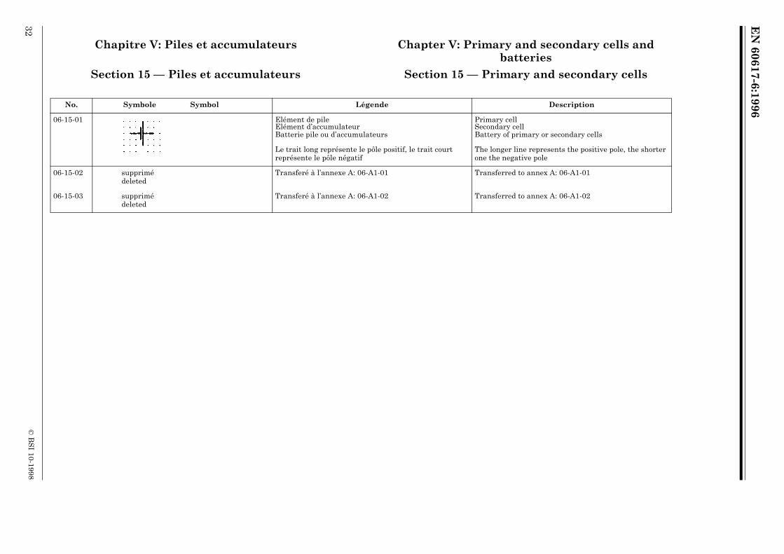
06-15-01 Elément de pile Elément d’accumulateurBatterie pile ou d’accumulateurs
Primary cellSecondary cellBattery of primary or secondary cells
Le trait long représente le pôle positif, le trait court représente le pôle négatif
The longer line represents the positive pole, the shorter one the negative pole
06-15-02 supprimé deleted
Transferé à l’annexe A: 06-A1-01 Transferred to annex A: 06-A1-01
06-15-03 supprimé deleted
Transferé à l’annexe A: 06-A1-02 Transferred to annex A: 06-A1-02

EN
60617-6:1996
© B
SI 10-1998
33
Chapitre VI: Générateurs de puissance Chapter VI: Power generators
Section 16 — Symbole général de generateurs non-rotatifs de puissance
Section 16 — General symbol for non-rotary power generators
No. Symbole Symbol Légende Description
06-16-01 Générateur, symbole général Generator, general symbol
Pour un générateur rotatif, utiliser le symbole 06-04-01.
For a rotary generator, use symbol 06-04-01.
Section 17 — Sources de chaleur Section 17 — Heat sources
No. Symbole Symbol Légende Description
06-17-01 Source de chaleur, symbole général Heat source, general symbol
06-17-02 Source de chaleur radioisotopique Radio-isotope heat source
06-17-03 Source de chaleur par combustion Combustion heat source
EN
60617-6:1996
34©
BS
I 10-1998
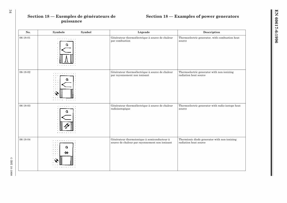
Section 18 — Exemples de générateurs de puissance
Section 18 — Examples of power generators
No. Symbole Symbol Légende Description
06-18-01 Générateur thermoélectrique à source de chaleur par combustion
Thermoelectric generator, with combustion heat source
06-18-02 Générateur thermoélectrique à source de chaleur par rayonnement non ionisant
Thermoelectric generator with non-ionizing radiation heat source
06-18-03 Générateur thermoélectrique à source de chaleur radioisotopique
Thermoelectric generator with radio-isotope heat source
06-18-04 Générateur thermoionique à semiconducteur à source de chaleur par rayonnement non ionisant
Thermionic diode generator with non-ionizing radiation heat source

EN
60617-6:1996
© B
SI 10-1998
35
06-18-05 Générateur thermoionique à semiconducteur à source de chaleur radioisotopique
Thermionic diode generator with radio-isotope heat source
06-18-06 Générateur photovoltaïque Photovoltaic generator
No. Symbole Symbol Légende Description

EN
60617-6:1996
36©
BS
I 10-1998
Section 19 — Régulateurs en boucle fermée Section 19 — Closed-loop controllers
No. Symbole Symbol Légende Description
06-19-01 Régulateur en boucle fermée Closed-loop controller
L’astérisque doit, soit être remplacé par un symbol littéral ou graphique indiquant le comportement de transition, soit être omis.Pour présenter un régulateur en boucle ouverte le symbole doit être utilisé avec une entrée seulement.
The asterisk shall either be replaced by letter(s) or a graph denoting the transition behavior, or be omitted.To indicate an open-loop controller the symbol shall be used with only one input.
EXEMPLE: EXAMPLE:

EN
60617-6:1996
© B
SI 10-1998
37
Annexe A (informative) Anciens symboles Annex A (informative) Older symbols
Cette annexe contient une sélection de symboles normalisés dans la CEI 617-6 (1983) qui sont maintenant supprimés. Ces symboles figurent ici seulement afin de faciliter la compréhension des schémas anciens.
This annex contains symbols standardized in IEC 617-6 (1983), which are now deleted. They are shown here for information purposes only to facilitate the comprehension of older diagrams.
(Dans cette annexe, les numéros de la publication de 1983 sont mis entre parenthèses.)
(In this annex the numbering from 1983-edition is quoted in parentheses.)
A1 — Piles et accumulateurs A1 — Primary and secondary cells and batteries
No. Symbole Symbol Légende Description
06-A1-01 Forme 1Form 1
Pile ou batterie d’accumulateurs Battery of primary or secunday cells
(06-15-02)
06-A1-02 Forme 2Form 2
(06-15-03)

EN
60617-6:1996
38©
BS
I 10-1998
Annex B (informative) English alphabetic index
AC series motor 06-06-01Auto-transformer 06-09-06Auto-transformer, single-phase 06-11-01Auto-transformer, single-phase with voltage regulation 06-11-05Auto-transformer, three-phase, connection star 06-11-03Battery of primary or secondary cells 06-15-01Brush (on slip-ring or commutator) 06-03-04Cell, primary 06-15-01Cell, secondary 06-15-01Choke 06-09-08Closed-loop controller 06-19-01Combustion heat source 06-17-03Commutating winding, element of 06-03-01Compensating winding, element of 06-03-01Controller, closed-loop 06-19-01Converter 06-14-01Converter, DC/DC 06-14-02Converter, rotary, DC/DC with common
exitation winding 06-05-05Converter, rotary, DC/DC with common
permanent magnet field 06-05-04Current transformer 06-09-10Current transformer with two secondary windings on
the same core and nine threaded primary conductors 06-13-12Current transformer with five passages of a
conductor acting as a primary winding 06-13-08Current transformer with one secondary winding
with one tapping 06-13-06Current transformer with three threaded primary
conductors 06-13-10Current transformer with two cores with one
secondary winding on each core 06-13-02Current transformer with two secondary windings
on one core 06-13-04DC series motor 06-05-01DC, generator 06-05-03DC/DC converter 06-14-02DC/DC Converter, rotary 06-05-04Delta, three-phase winding 06-02-05
Element of, commutating winding 06-03-01Element of, compensating winding 06-03-01Element of, separate winding 06-03-03Element of, series winding 06-03-02Element of, shunt winding 06-03-03Four-phase winding with neutral brought out 06-02-03Generator 06-04-01Generator, DC 06-05-03Generator, general symbol 06-16-01Generator, hand 06-04-04Generator, magneto caller 06-04-04Generator, power, photovoltaic 06-18-06Generator, power, thermionic diode with
non-ionizing radiation heat source 06-18-04Generator, power, thermionic diode with
radio-isotope heat source 06-18-05Generator, power, thermoelectric, with
combustion heat source 06-18-01Generator, power, thermoelectric, with non-ionizing
radiation heat source 06-18-02Generator, power, thermoelectric, with
radio-isotope heat source 06-18-03Generator, synchronous, three-phase, both ends
of each phase winding brought out 06-07-04Generator, synchronous, three-phase, star
connected, neutral brought out 06-07-03Generator, three-phase, permanent magnet 06-07-01Hand-generator 06-04-04Heat source 06-17-01Heat source, combustion 06-17-03Induction motor, single-phase, squirrel-cage,
ends of split-phase brought out 06-08-02Induction motor, three-phase, squirrel cage 06-08-01Induction motor, three-phase, star-connected,
with built-in automatic starter 06-08-04Induction motor, three-phase, with wound rotor 06-08-03lnduction regulator, three-phase 06-12-01lnverter 06-14-05

EN
60617-6:1996
© B
SI 10-1998
39
Linear induction motor, three-phase, movement only in one direction 06-08-05
Linear motor 06-04-02m-phase winding, phases not interconnected 06-01-05Machine 06-04-01Machine, element, brush 06-03-04Machine, hand-generator 06-04-04Machine, linear motor 06-04-02Machine, magneto caller 06-04-04Machine, stepping motor 06-04-03Magneto caller 06-05-00Motor 06-04-01Motor, AC, repulsion, single-phase 06-06-02Motor, AC, series, single-phase 06-06-01Motor, AC, series, three-phase 06-06-03Motor, DC, series 06-05-01Motor, DC, shunt 06-05-02Motor, induction, linear, three-phase, movement
only in one direction 06-08-05Motor, induction, single-phase, squirrel-cage,
ends of split-phase brought out 06-08-02Motor, induction, three-phase, squirrel cage 06-08-01Motor, induction, three-phase, star-connected,
with built-in automatic starter 06-08-04Motor, induction, three-phase, with wound rotor 06-08-03Motor, linear 06-04-02Motor, stepping 06-04-03Motor, synchronous, single-phase 06-07-02Open delta, three-phase winding 06-02-06Photovoltaic generator 06-18-06Power converter 06-14-00Power converter, DC/DC 06-14-02Power converter, inverter 06-14-05Power converter, rectifier 06-14-03Power converter, rectifier in full wave (bridge) connection 06-14-04Power converter, rectifier/inverter 06-14-06Primary cell 06-15-01Pulse transformer 06-09-10Pulse transformer with three threaded primary
conductors 06-13-10Pulse transformer with two secondary windings on the
same core and nine threaded primary conductors 06-13-12Reactor 06-09-08Rectifier 06-14-03
Rectifier in full wave (bridge) connection 06-14-04Rectifier/inverter 06-14-06Regulator, three-phase, induction 06-12-01Repulsion motor, single-phase 06-06-02Rotary converter 06-04-01Rotary converter, DC/DC with common exitation winding 06-05-05Rotary converter, DC/DC with common permanent
magnet field 06-05-04Rotary converter, synchronous, three-phase,
shunt-excited 06-08-00Secondary cell 06-15-01Separate winding, element of 06-03-03Series motor, DC 06-05-01Series motor, single-phase 06-06-01Series motor, three-phase 06-06-03Series winding, element of 06-03-02Shunt motor, DC 06-05-02Shunt winding, element of 06-03-03Single-phase transformer with two windings and screen 06-10-01Six separate windings 06-01-03Six-phase winding, double delta 06-02-10Six-phase winding, fork with neutral brought out 06-02-13Six-phase winding, polygon 06-02-11Six-phase winding, star 06-02-12Star, three-phase winding 06-02-07Star-zigzag, transformer, three-phase, connection 06-10-15Stepping motor 06-04-03Synchronous generator 06-04-01Synchronous generator, three-phase, both ends of each
phase winding brought out 06-07-04Synchronous generator, three-phase, permanent magnet 06-07-00Synchronous generator, three-phase, star connected,
neutral brought out 06-07-03Synchronous machine, synchronous generator,
three-phase, permanent magnet 06-07-01Synchronous machine, synchronous motor,
single-phase 06-07-02Synchronous motor 06-04-01Synchronous motor, single-phase 06-07-02Synchronous rotary converter, three-phase,
shunt-excited 06-07-05Thermionic diode generator with non-ionizing
radiation heat source 06-18-04

EN
60617-6:1996
40©
BS
I 10-1998
Thermionic diode generator with radio-isotope heat source 06-18-05
Thermoelectric generator with combustion heat source 06-18-00
Thermoelectric generator with non-ionizing radiation heat source 06-18-02
Thermoelectric generator with radio-isotope heat source 06-18-03
Three seperate windings 06-01-02Three-phase bank of single-phase transformers,
connection star-delta 06-10-11Three-phase induction regulator 06-12-01Three-phase transformer with four tappings(taps) 06-10-09Three-phase transformer with on-load tap changer 06-10-13Three-phase transformer, connection star-delta 06-10-07Three-phase transformer, connection star-star-delta 06-10-17Three-phase transformer, connection star-zigzag 06-10-15Three-phase winding, delta 06-02-05Three-phase winding, interconnected star 06-02-07Three-phase winding, open delta 06-02-06Three-phase winding, phases not interconnected 06-01-04Three-phase winding, star, with neutral brought out 06-02-08Three-phase winding, T 06-02-04Three-phase winding, V (60°) 06-02-02Three-phase winding, zigzag 06-02-09Transformer choke 06-09-08Transformer reactor 06-09-08Transformer with centre tapping on one winding 06-10-03Transformer with three windings 06-09-04Transformer with two windings 06-09-01Transformer with two windings, shown with voltage
polarity indicators 06-09-03Transformer with variable coupling 06-10-05Transformer, current 06-09-10Transformer, measuring current, with two cores with
one secondary winding on each core 06-13-02Transformer, measuring current, with two secondary
windings on one core 06-13-04Transformer, measuring current, with five passages of
a conductor acting as a primary winding 06-13-08Transformer, measuring current, with one secondary
winding with one tapping 06-13-06
Transformer, measuring current, with three threaded primary conductors 06-13-10
Transformer, measuring current, with two secondary windings on the same core and nine threaded primary conductors 06-13-12
Transformer, measuring pulse, with three threaded primary conductors 06-13-10
Transformer, measuring pulse, with two secondary windings on the same core and nine threaded primary conductors 06-13-12
Transformer, measuring voltage 06-13-01ATransformer, pulse 06-09-10Transformer, single-phase, with two windings and
screen 06-10-01Transformer, three-phase bank of single-phase
transformers, connection star-delta 06-10-11Transformer, three-phase, connection star-delta 06-10-07Transformer, three-phase, connection star-star-delta 06-10-17Transformer, three-phase, connection star-zigzag 06-10-15Transformer, three-phase, with four tappings(taps) 06-10-09Transformer, three-phase, with on-load tap changer 06-10-13Transformer, voltage 06-13-01ATwo-phase winding 06-02-01Two-phase winding, four-wire 06-01-06Voltage transformer 06-13-01AWinding for machines, commutating 06-03-01Winding for machines, compensating 06-03-01Winding for machines, separate 06-03-03Winding for machines, series 06-03-02Winding for machines, shunt 06-03-03Winding, internally connected, four-phase, with
neutral brought out 06-02-03Winding, internally connected, six-phase,
double delta 06-02-10Winding, internally connected, six-phase, fork with
neutral brought out 06-02-13Winding, internally connected, six-phase, polygon 06-02-11Winding, internally connected, six-phase, star 06-02-12Winding, internally connected, three-phase V (60°) 06-02-02Winding, internally connected, three-phase, delta 06-02-05Winding, internally connected, three-phase, star 06-02-07Winding, internally connected, three-phase, T 06-02-04Winding, internally connected, three-phase, zigzag 06-02-09

EN
60617-6:1996
© B
SI 10-1998
41
Winding, internally connected, two-phase 06-02-00Winding, one 06-01-01Winding, seperate, m-phase winding, phases not
interconnected 06-01-05Winding, seperate, one winding 06-01-01Winding, seperate, six separate windings 06-01-03Winding, seperate, three seperate windings 06-01-02Winding, seperate, three-phase winding, phases not
interconnected 06-01-04Zigzag, three-phase winding 06-02-09

BSI389 Chiswick High RoadLondonW4 4AL
|||||||||||||||||||||||||||||||||||||||||||||||||||||||||||||||||||||||||||||||||||||||||||||||||||||||||||||||||||||||||||||||
BSI Ð British Standards Institution
BSI is the independent national body responsible for preparing British Standards. Itpresents the UK view on standards in Europe and at the international level. It isincorporated by Royal Charter.
Revisions
British Standards are updated by amendment or revision. Users of British Standardsshould make sure that they possess the latest amendments or editions.
It is the constant aim of BSI to improve the quality of our products and services. Wewould be grateful if anyone finding an inaccuracy or ambiguity while using thisBritish Standard would inform the Secretary of the technical committee responsible,the identity of which can be found on the inside front cover. Tel: 020 8996 9000.Fax: 020 8996 7400.
BSI offers members an individual updating service called PLUS which ensures thatsubscribers automatically receive the latest editions of standards.
Buying standards
Orders for all BSI, international and foreign standards publications should beaddressed to Customer Services. Tel: 020 8996 9001. Fax: 020 8996 7001.
In response to orders for international standards, it is BSI policy to supply the BSIimplementation of those that have been published as British Standards, unlessotherwise requested.
Information on standards
BSI provides a wide range of information on national, European and internationalstandards through its Library and its Technical Help to Exporters Service. VariousBSI electronic information services are also available which give details on all itsproducts and services. Contact the Information Centre. Tel: 020 8996 7111.Fax: 020 8996 7048.
Subscribing members of BSI are kept up to date with standards developments andreceive substantial discounts on the purchase price of standards. For details ofthese and other benefits contact Membership Administration. Tel: 020 8996 7002.Fax: 020 8996 7001.
Copyright
Copyright subsists in all BSI publications. BSI also holds the copyright, in the UK, ofthe publications of the international standardization bodies. Except as permittedunder the Copyright, Designs and Patents Act 1988 no extract may be reproduced,stored in a retrieval system or transmitted in any form or by any means ± electronic,photocopying, recording or otherwise ± without prior written permission from BSI.
This does not preclude the free use, in the course of implementing the standard, ofnecessary details such as symbols, and size, type or grade designations. If thesedetails are to be used for any other purpose than implementation then the priorwritten permission of BSI must be obtained.
If permission is granted, the terms may include royalty payments or a licensingagreement. Details and advice can be obtained from the Copyright Manager.Tel: 020 8996 7070.