Graphical symbols for diagrams - OILWEB · 2015-07-02 · of IEC 617-11, prepared by SC 3A,...
52
BRITISH STANDARD BS EN 60617-11:1997 IEC 617-11: 1996 Graphical symbols for diagrams — Part 11: Architectural and topographical installation plans and diagrams The European Standard EN 60617-11:1996 has the status of a British Standard ICS 01.080.30; 29.020
Transcript of Graphical symbols for diagrams - OILWEB · 2015-07-02 · of IEC 617-11, prepared by SC 3A,...
BRITISH STANDARD BS EN60617-11:1997 IEC 617-11:1996
Graphical symbols for diagrams —
Part 11: Architectural and topographical installation plans and diagrams
The European Standard EN 60617-11:1996 has the status of a British Standard
ICS 01.080.30; 29.020
BS EN 60617-11:1997
This British Standard, having been prepared under the direction of the Electrotechnical Sector Board, was publishedunder the authority of the Standards Board and comesinto effect on 15 February 1997
© BSI 10-1998
The following BSI references relate to the work on this standard:Committee reference GEL/3Draft for comment 92/28845 DC
ISBN 0 580 26887 X
Committees responsible for this British Standard
The preparation of this British Standard was entrusted to Technical Committee GEL/3, Documentation and graphical symbols, upon which the following bodies were represented:
British Photographic AssociationConsumer Policy Committee of BSIFederation of the Electronics IndustryGAMBICA (BEAMA Ltd.)Transmission and Distribution Association (BEAMA Ltd.)
Amendments issued since publication
Amd. No. Date Comments

BS EN 60617-11:1997
© BSI 10-1998 i
Contents
PageCommittees responsible Inside front coverNational foreword ii
Foreword 2Text of EN 60617-11 3
List of references Inside back cover
BS EN 60617-11:1997
ii © BSI 10-1998
National foreword
This British Standard has been prepared by Technical Committee GEL/3 and is the English language version of EN 60617-11:1996 Graphical symbols for diagrams — Part 11: Architectural and topographical installation plans and diagrams, published by the European Committee for Electrotechnical Standardization (CENELEC). It is identical with IEC 617-11:1996 published by the International Electrotechnical Commission (IEC).This British Standard supersedes BS 3939-11:1985, which is withdrawn.NOTE The French language version of the alphabetic index has not been included.
A British Standard does not purport to include all the necessary provisions of a contract. Users of British Standards are responsible for their correct application.
Compliance with a British Standard does not of itself confer immunity from legal obligations.
Summary of pagesThis document comprises a front cover, an inside front cover, pages i and ii, the EN title page, pages 2 to 46, an inside back cover and a back cover.This standard has been updated (see copyright date) and may have had amendments incorporated. This will be indicated in the amendment table on the inside front cover.
EUROPEAN STANDARD
NORME EUROPÉENNE
EUROPÄISCHE NORM
EN 60617-11
June 1996
ICS 01.080.30
Descriptors: Electrical installation, circuit diagram, electric diagram, electrical symbol
English version
Graphical symbols for diagrams Part 11: Architectural and topographical installation
plans and diagrams(IEC 617-11:1996)
Symboles graphiques pour schémas Partie 11: Schémas et plans d’installation, architecturaux et topographiques (CEI 617-11:1996)
Graphische Symbole für Schaltpläne Teil 11: Gebäudebezogene und topographische Installationspläne und Schaltpläne (IEC 617-11:1996)
This European Standard was approved by CENELEC on 1996-03-05.CENELEC members are bound to comply with the CEN/CENELEC InternalRegulations which stipulate the conditions for giving this European Standardthe status of a national standard without any alteration.Up-to-date lists and bibliographical references concerning such nationalstandards may be obtained on application to the Central Secretariat or to anyCENELEC member.This European Standard exists in three official versions (English, French,German). A version in any other language made by translation under theresponsibility of a CENELEC member into its own language and notified to theCentral Secretariat has the same status as the official versions.CENELEC members are the national electrotechnical committees of Austria,Belgium, Denmark, Finland, France, Germany, Greece, Iceland, Ireland, Italy,Luxembourg, Netherlands, Norway, Portugal, Spain, Sweden, Switzerland andUnited Kingdom.
CENELECEuropean Committee for Electrotechnical Standardization
Comité Européen de Normalisation ElectrotechniqueEuropäisches Komitee für Elektrotechnische Normung
Central Secretariat: rue de Stassart 35, B-1050 Brussels
© 1996 Copyright reserved to CENELEC membersRef. No. EN 60617-11:1996 E

EN 60617-11:1996
© BSI 10-19982
Foreword
The text of document 3A/389/FDIS, future edition 2 of IEC 617-11, prepared by SC 3A, Graphical symbols for diagrams, of IEC TC 3, Documentation and graphical symbols, was submitted to the IEC-CENELEC parallel vote and was approved by CENELEC as EN 60617-11 on 1996-03-05.The following dates were fixed:
Contents
PageIntroduction 3Chapter I: Generating stations and substationsSection 1 General symbols 4Section 2 Specific types of generating stations and substations 6Chapter II: NetworksSection 3 Lines 9Section 4 Miscellaneous items 11Chapter III: Cabled distribution systems for sound and televisionSection 5 Head ends 13Section 6 Amplifiers 14Section 7 Splitters and directional couplers 15Section 8 Tap-off and system outlets 16Section 9 Equalizers and attenuators 17Section 10 Power feeding devices 18Chapter IV: Installations in buildingsSection 11 Identification of specific conductors 19Section 12 Wiring 20Section 13 Socket outlets 21Section 14 Switches 23Section 15 Lighting outlets and fittings 26Section 16 Miscellaneous 28Section 17 Trunking systems 29Chapter V: Outdoor installationsSection 18 Airport navigation lights and indicators 35Annex A (informative) English alphabetic index 41Table 1 — Indication of colours 39Table 2 — Indication of colours 40
– latest date by which the EN has to be implemented at national level by publication of an identical national standard or by endorsement (dop) 1997-02-01
– latest date by which the national standards conflicting with the EN have to be withdrawn (dow) 1997-02-01

EN 60617-11:1996
© BSI 10-1998 3
IntroductionThis part of IEC 617 forms an element of a series which deals with graphical symbols for diagrams.The series consists of the following parts:
— Part 1: General information, general index. Cross-reference tables;— Part 2: Symbol elements, qualifying symbols and other symbols having general application;— Part 3: Conductors and connecting devices;— Part 4: Basic passive components;— Part 5: Semiconductors and electron tubes;— Part 6: Production and conversion of electrical energy;— Part 7: Switchgear, controlgear and protective devices;— Part 8: Measuring instruments, lamps and signalling devices;— Part 9: Telecommunications: Switching and peripheral equipment;— Part 10: Telecommunications: Transmission;— Part 11: Architectural and topographical installation plans and diagrams;— Part 12: Binary logic elements;— Part 13: Analogue elements.
The scope and the normative references for this series are given in IEC 617-1.
Symbols have been designed in accordance with requirements given in the future ISO 11714-11). The module size M = 2,5 mm has been used. For better readability smaller symbols in this standard have been enlarged to double size and are marked “200 %” in the symbol column. To save space larger symbols have been reduced to half size and are marked “50 %” in the symbol column. In accordance with the future ISO 11714-1, clause 7, symbol dimensions (for instance height) may be modified in order to make space for a greater number of terminals or for other layout requirements. In all cases, whether the size is enlarged or reduced, or dimensions modified, the thickness of the original line should be maintained without scaling.The symbols in this standard are laid out in such a way that the distance between connecting lines is a multiple of a certain module. The module 2M has been chosen to provide enough space for a required terminal designation. The symbols have been drawn to a size convenient for comprehension, using the same grid consistently in the representation of all symbols.All symbols are designed within a grid in a computer-aided draughting system. The grid which was used has been reproduced in the background of the symbols.The indexes in Annex A and B include an alphabetic list of symbol names and their corresponding number. The symbol names are based on the description of the symbols of this part. A general index including an alphabetic list of symbols of all parts is given in IEC 617-1.
1) At present, at the stage of Draft International Standard (document 3/563/DIS).

EN
60617-11:1996
4©
BS
I 10-1998
Regles generales General rulesLa présente publication regroupe des symboles spécialement créés pour les cartes et plans à petite échelle pour lesquels les symboles donnés dans les autres parties ne pourraient convenir. Ces derniers sont cependant également utilisables.
This publication contains symbols developed for small-scale maps or plans for which the symbols given in the other parts would not be quite suitable. The latter may however be used as well.
Sur les cartes, le centre d’un symbole, tel que ceux des sections 1, 2 ou 5 par exemple, doit correspondre à l’emplacement exact du centre de l’entité.
On maps, the centre of a symbol, such as those of sections 1, 2 or 5 for example, shall correspond with the exact location of the centre of the entity.
Chapitre I: Centrales et postes électriques Chapter I: Generating stations and substations
Section 1 — Symboles généraux Section 1 — General Symbols1.1 Un cadre rectangulaire peut être utilisé au lieu d’un cadre carré. 1.1 A rectangular outline may be used instead of a square.
1.2 Pour les cartes à petite échelle les surfaces hachurées peuvent être remplies. 1.2 On small scale maps it may be desirable to replace the hatched areas in the symbols by completely filled-in areas.
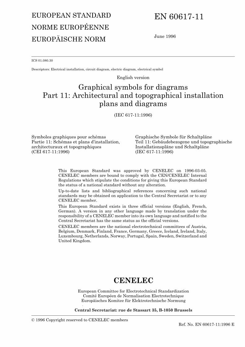
No. Symbole Symbol Légende Description
En projet Planned
En service ou indéterminé In service or unspecified
11-01-01 Centrale Generating station
11-01-02
EN
60617-11:1996
© B
SI 10-1998
5
11-01-03 Centrale de production combinée d’énergie électrique et de chaleur
Combined electric and heat generating station
11-01-04
11-01-05 Sous-stationPoste
Substation
11-01-06
No. Symbole Symbol Légende Description
En projet Planned
En service ou indéterminé In service or unspecified

EN
60617-11:1996
6©
BS
I 10-1998
Section 2 — Types particuliers de centrales et postes électriques
Section 2 — Specific types of generating stations and substations
No. Symbole Symbol Légende Description
En projetPlanned
En service ou indéterminéIn service or unspecified
11-02-01 Centrale hydraulique Hydroelectric generating station
11-02-02
11-02-03 Centrale thermique
EXEMPLES:— charbon— lignite— fuel— gaz
Thermoelectric generating station
EXAMPLES:— coal— lignite— oil— gas
11-02-04
11-02-05 Centrale nucléaire Nuclear energy generating station
11-02-06
EN
60617-11:1996
© B
SI 10-1998
7
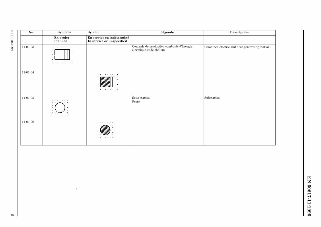
11-02-07 Centrale géothermique Geothermic generating station
11-02-08
11-02-09 Centrale solaire Solar generating station
11-02-10
11-02-11 Centrale éolienne Wind generating station
11-02-12
No. Symbole Symbol Légende Description
En projetPlanned
En service ou indéterminéIn service or unspecified

EN
60617-11:1996
8©
BS
I 10-1998
11-02-13 Centrale à plasmaMHD (magnéto-hydro-dynamique)
Plasma generating stationMHD (magneto-hydrodynamic)
11-02-14
11-02-15 Sous-station de conversionFigurée pour courant continu converti en courant alternatif
Converting substationThe symbol is shown with conversion from DC to AC
11-02-16
No. Symbole Symbol Légende Description
En projetPlanned
En service ou indéterminéIn service or unspecified

EN
60617-11:1996
© B
SI 10-1998
9
Chapitre II: Réseaux Chapter II: Networks
Section 3 — Lignes Section 2 — Lines3.1 On retrouve des exemples de ligne en 03-01-01. 3.1 EXAMPLES of lines are given in 03-01-01.
No. Symbole Symbol Légende Description
11-03-01 Ligne souterraine Underground line
11-03-02 Ligne immergée Submarine line
11-03-03 Ligne aérienne Overhead line
11-03-04 Ligne dans un conduitLigne dans un fourreau
Des informations complémentaires peuvent être données au-dessus de la ligne représentant le chemin des conduits, par exemple le nombre de voies.
Line within a ductLine within a pipe
Additional information may be shown above the line representing the duct route, for example the number of ways.
11-03-05 EXEMPLE:Ligne dans un conduit à six voies
EXAMPLE:Line within a six-way-duct
11-03-06 Ligne passant à travers une chambre d’accès Line passing through an access chamber
EN
60617-11:1996
10©
BS
I 10-1998
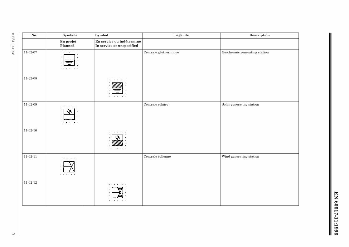
11-03-07 Ligne avec point de raccordement enterré Line with a buried joint
11-03-08 Ligne avec bouchon d’étanchéité (gaz ou huile) Line with gas or oil block
11-03-09 Ligne avec vanne d’arrêt de gaz ou d’huile Line with gas or oil stop valve
11-03-10 Ligne avec bouchon d’étanchéité à gaz ou huile, avec contournement
Line with gas or oil block by-pass
11-03-11 Alimentation en courant alternatif par lignes de télécommunications
AC power feeding on telecommunication lines
11-03-12 Alimentation en courant continu par lignes de télécommunications
DC power feeding on telecommunication lines
No. Symbole Symbol Légende Description

EN
60617-11:1996
© B
SI 10-1998
11
Section 4 — Éléments divers Section 4 — Miscellaneous items
No. Symbole Symbol Légende Description
11-04-01 Cabine ou armoire pour installation extérieure, symbole général
Des symboles distinctifs peuvent préciser quels appareils sont placés dans la cabine.
Overground weather-proof enclosure, general symbol
Qualifying symbols or designations may be used to indicate the apparatus contained in the enclosure.
11-04-02 EXEMPLE:
Cabine d’amplification
EXAMPLE:
Amplifying point in a weather-proof enclosure
11-04-03 Point de répartition
Les entrées et les sorties peuvent être disposées selon besoin.
Cross-connection point
Inputs and outputs may be oriented as required.
11-04-04 Concentrateur de lignesConnecteur automatique de lignes
Le symbole représente un transmission du signal de gauche à droite. Un groupe de lignes (à gauche) est concentré en un nombre restreint de lignes (à droite).
Line concentratorAutomatic line connector
The symbol is shown for signal transmission from left to right. A number of lines on the left are concentrated for fewer lines on the right.
11-04-05 EXEMPLE:Concentrateur de lignes sur poteau
EXAMPLE:
Line concentrator on a pole
11-04-06 Dispositif évitant le glissement d’un câble
Par rapport à la chambre d’accès il convient de figurer le symbole du côté vers lequel le glissement est à éviter.
Anti-creepage device for cable
The symbol should be shown on the “creepout” side of the access chamber.
11-04-07 EXEMPLE:
Chambre d’accès avec dispositif évitant le glissement du câble
Le symbole montre que le glissement vers la gauche est évité.
EXAMPLE:
Access chamber with a cable having anti-creepage device
The symbol shows that creepage towards the left is prevented.
EN
60617-11:1996
12©
BS
I 10-1998
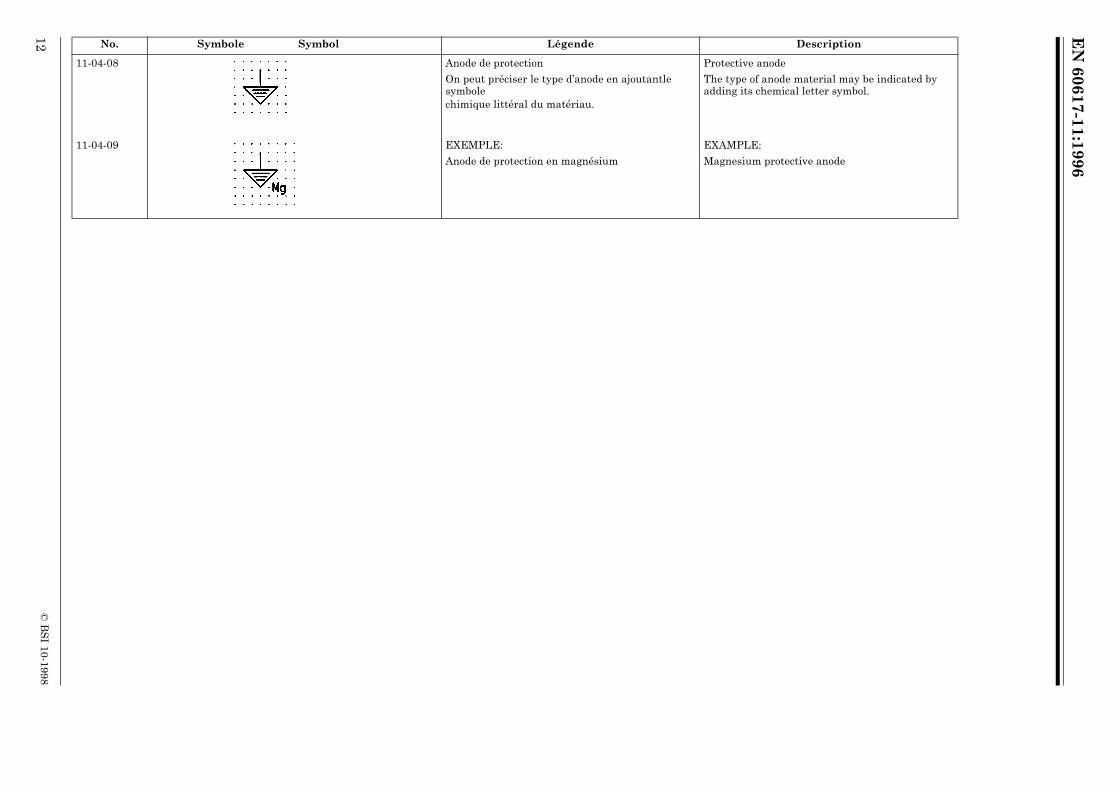
11-04-08 Anode de protection
On peut préciser le type d’anode en ajoutantle symbolechimique littéral du matériau.
Protective anode
The type of anode material may be indicated by adding its chemical letter symbol.
11-04-09 EXEMPLE:
Anode de protection en magnésium
EXAMPLE:
Magnesium protective anode
No. Symbole Symbol Légende Description
EN
60617-11:1996
© B
SI 10-1998
13
Chapitre III: Distribution par câbles de programmes de sons et d’images
Chapter III: Cabled distribution systems for sound and television
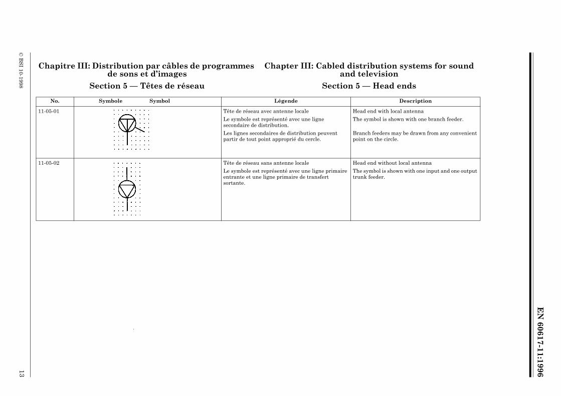
Section 5 — Têtes de réseau Section 5 — Head ends
No. Symbole Symbol Légende Description
11-05-01 Tête de réseau avec antenne locale
Le symbole est représenté avec une ligne secondaire de distribution.
Les lignes secondaires de distribution peuvent partir de tout point approprié du cercle.
Head end with local antenna
The symbol is shown with one branch feeder.
Branch feeders may be drawn from any convenient point on the circle.
11-05-02 Tête de réseau sans antenne locale
Le symbole est représenté avec une ligne primaire entrante et une ligne primaire de transfert sortante.
Head end without local antenna
The symbol is shown with one input and one output trunk feeder.

EN
60617-11:1996
14©
BS
I 10-1998
Section 6 — Amplificateurs Section 6 — Amplifiers
No. Symbole Symbol Légende Description
11-06-01 Amplificateur de dérivation
Le symbole est représenté avec trois lignes dérivées, secondaires ou tertiaires.
1. Le point sert à distinguer une sortie à niveau relativement élevé.
2. Les tracés des lignes dérivées secondaire ou tertiares peuvent quitter les côtés obliques du symbole sous tout angle approprié.
Bridger amplifier
The symbol is shown with three branch or spur feeder outputs.
1. The dot is used to distinguish an output at a relatively higher level.
2. Branch or spur feeders may leave the sloping sides of the symbol at any convenient angle.
11-06-02 Amplificateur de ligne avec dérivations
Le symbole est représenté avec trois lignes secondaires dérivées.
Trunk bridging amplifier assembly
The symbol is shown with three branch feeder outputs.
11-06-03 Amplificateur terminal de ligne, secondaire ou tertiaire
Le symbole est représenté avec une ligne tertiares de distribution sortante.
End of amplifier (branch or spur feeder)
The symbol is shown with one spur feeder output.
11-06-04 Amplificateur pour réseau de distribution avec voie de retour
Amplifier with return channel

EN
60617-11:1996
© B
SI 10-1998
15
Section 7 — Répartiteurs et coupleurs directifs Section 7 — Splitters and directional couplers
No. Symbole Symbol Légende Description
11-07-01 Répartiteur à deux voies Splitter, two-way
11-07-02 Répartiteur à trois voies
Le symbole est représenté avec une sortie à niveau plus élevé.
Les règles dans 11-06-01 sont applicables.
Splitter, three-way
The symbol is shown with one higher level output.
The rules in 11-06-01 apply.
11-07-03 Coupleur directif Directional coupler
EN
60617-11:1996
16©
BS
I 10-1998
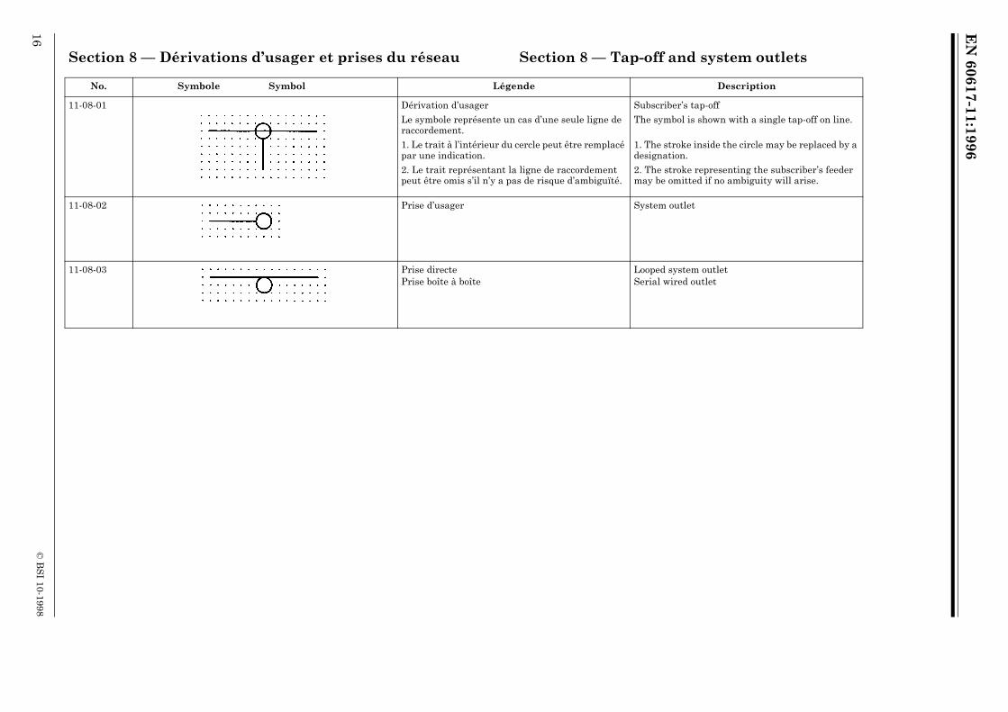
Section 8 — Dérivations d’usager et prises du réseau Section 8 — Tap-off and system outlets
No. Symbole Symbol Légende Description
11-08-01 Dérivation d’usager
Le symbole représente un cas d’une seule ligne de raccordement.
1. Le trait à l’intérieur du cercle peut être remplacé par une indication.
2. Le trait représentant la ligne de raccordement peut être omis s’il n’y a pas de risque d’ambiguïté.
Subscriber’s tap-off
The symbol is shown with a single tap-off on line.
1. The stroke inside the circle may be replaced by a designation.
2. The stroke representing the subscriber’s feeder may be omitted if no ambiguity will arise.
11-08-02 Prise d’usager System outlet
11-08-03 Prise directePrise boîte à boîte
Looped system outletSerial wired outlet

EN
60617-11:1996
© B
SI 10-1998
17
Section 9 — Égaliseurs et affaiblisseurs Section 9 — Equalizers and attenuators
No. Symbole Symbol Légende Description
11-09-01 Egaliseur Equalizer
11-09-02 Egaliseur variable Variable equalizer
11-09-03 Affaiblisseur (Symbole utilisable sur cartes)
Le symbole 10-16-01 peut aussi être utilisé.
Attenuator (Map symbol)
Symbol 10-16-01 may also be used.

EN
60617-11:1996
18©
BS
I 10-1998
Section 10 — Dispositifs d’alimentation Section 10 — Power feeding devices
No. Symbole Symbol Légende Description
11-10-01 Dispositif d’alimentation de ligne
Figuré pour courant alternatif.
Line power unit
AC type shown.
11-10-02 Dispositif de blocage d’alimentation
Figuré sur une ligne de distribution.
Power block
The symbol is shown in a distribution feeder.
11-10-03 Point d’injection de l’alimentation Power feeding injection point
EN
60617-11:1996
© B
SI 10-1998
19
Chapitre IV: Installations dans les bâtiments Chapter IV: Installations in buildings
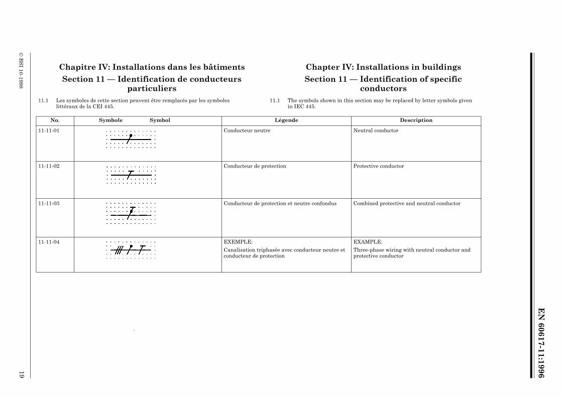
Section 11 — Identification de conducteurs particuliers
Section 11 — Identification of specific conductors
11.1 Les symboles de cette section peuvent être remplacés par les symboles littéraux de la CEI 445.
11.1 The symbols shown in this section may be replaced by letter symbols given in IEC 445.
No. Symbole Symbol Légende Description
11-11-01 Conducteur neutre Neutral conductor
11-11-02 Conducteur de protection Protective conductor
11-11-03 Conducteur de protection et neutre confondus Combined protective and neutral conductor
11-11-04 EXEMPLE:
Canalisation triphasée avec conducteur neutre et conducteur de protection
EXAMPLE:
Three-phase wiring with neutral conductor and protective conductor
EN
60617-11:1996
20©
BS
I 10-1998
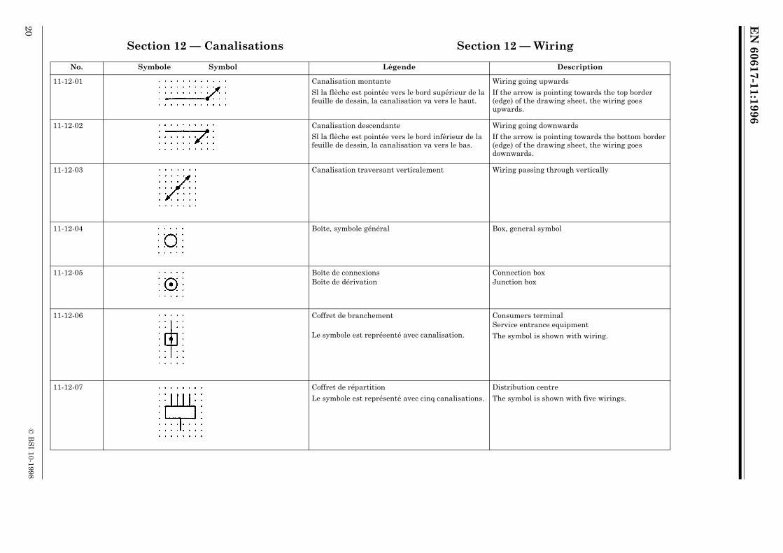
Section 12 — Canalisations Section 12 — Wiring
No. Symbole Symbol Légende Description
11-12-01 Canalisation montante
Sl la flèche est pointée vers le bord supérieur de la feuille de dessin, la canalisation va vers le haut.
Wiring going upwards
If the arrow is pointing towards the top border (edge) of the drawing sheet, the wiring goes upwards.
11-12-02 Canalisation descendante
Sl la flèche est pointée vers le bord inférieur de la feuille de dessin, la canalisation va vers le bas.
Wiring going downwards
If the arrow is pointing towards the bottom border (edge) of the drawing sheet, the wiring goes downwards.
11-12-03 Canalisation traversant verticalement Wiring passing through vertically
11-12-04 Boîte, symbole général Box, general symbol
11-12-05 Boîte de connexionsBoîte de dérivation
Connection boxJunction box
11-12-06 Coffret de branchement
Le symbole est représenté avec canalisation.
Consumers terminalService entrance equipment
The symbol is shown with wiring.
11-12-07 Coffret de répartition
Le symbole est représenté avec cinq canalisations.
Distribution centre
The symbol is shown with five wirings.
EN
60617-11:1996
© B
SI 10-1998
21
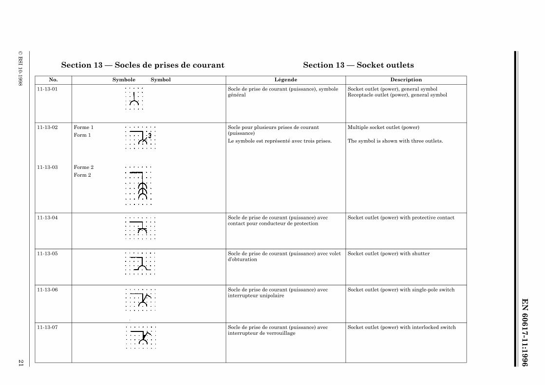
Section 13 — Socles de prises de courant Section 13 — Socket outlets
No. Symbole Symbol Légende Description
11-13-01 Socle de prise de courant (puissance), symbole général
Socket outlet (power), general symbolReceptacle outlet (power), general symbol
11-13-02 Forme 1 Form 1
Socle pour plusieurs prises de courant (puissance)
Le symbole est représenté avec trois prises.
Multiple socket outlet (power)
The symbol is shown with three outlets.
11-13-03 Forme 2 Form 2
11-13-04 Socle de prise de courant (puissance) avec contact pour conducteur de protection
Socket outlet (power) with protective contact
11-13-05 Socle de prise de courant (puissance) avec volet d’obturation
Socket outlet (power) with shutter
11-13-06 Socle de prise de courant (puissance) avec interrupteur unipolaire
Socket outlet (power) with single-pole switch
11-13-07 Socle de prise de courant (puissance) avec interrupteur de verrouillage
Socket outlet (power) with interlocked switch

EN
60617-11:1996
22©
BS
I 10-1998
11-13-08 Socle de prise de courant avec transformateur de séparation, par exemple: prise pour rasoir
Socket outlet (power) with isolating transformer, for example: shaver outlet
11-13-09 Socle de prise pour terminal de télécommunication, symbole général
Les désignations en conformité avec les normes respectives de la CEI et de l’ISO peuvent être employées pour distinguer les différents types de prises.
Socket outlet (telecommunications), general symbol
Designations in accordance with relevant IEC or ISO standards, may be used to distinguish different types of outlets.
TP = téléphone TP = telephone
FX = télécopie FX = telefax
M = microphone M = microphone
= haut-parleur = loudspeaker
FM = modulation de fréquence FM = frequency modulation
TV = télévision TV = television
TX = télex TX = telex
No. Symbole Symbol Légende Description

EN
60617-11:1996
© B
SI 10-1998
23
Section 14 — Interrupteurs Section 14 — Switches
No. Symbole Symbol Légende Description
11-14-01 Interrupteur, symbole général Switch, general symbol
11-14-02 Interrupteur à lampe témoin Switch with pilot light
11-14-03 Interrupteur à temps de fermeture limité, unipolaire
Period limiting switch, single pole
11-14-04 Interrupteur, bipolaire Two pole switch
11-14-05 Commutateur unipolaire, par exemple pour différents niveaux d’éclairage
Multiposition single pole switch, for example for different degrees of lighting
11-14-06 Interrupteur unipolaire va-et-vient Two-way single pole switch
EN
60617-11:1996
24©
BS
I 10-1998
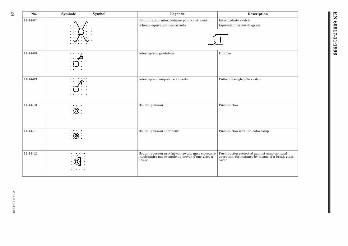
11-14-07 Commutateur intermédiaire pour va-et-vient
Schéma équivalent des circuits
Intermediate switch
Equivalent circuit diagram
11-14-08 Interrupteur gradateur Dimmer
11-14-09 Interrupteur unipolaire à tirette Pull-cord single pole switch
11-14-10 Bouton-poussoir Push-button
11-14-11 Bouton-poussoir lumineux Push-button with indicator lamp
11-14-12 Bouton-poussoir protégé contre une mise en oeuvre involontaire par exemple au moyen d’une glace à briser
Push-button protected against unintentional operation, for instance by means of a break-glass cover
No. Symbole Symbol Légende Description

EN
60617-11:1996
© B
SI 10-1998
25
11-14-13 MinuterieAppareil limiteur de durée
TimerPeriod limiting equipment
11-14-14 Interrupteur horaire Time switch
11-14-15 Dispositif de commande ou de contrôle par cléDispositif de contrôle par vigile
Key-operated switchWatchman’s system device
No. Symbole Symbol Légende Description
EN
60617-11:1996
26©
BS
I 10-1998
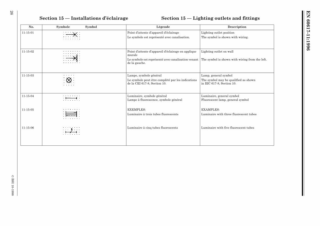
Section 15 — Installations d’éclairage Section 15 — Lighting outlets and fittings
No. Symbole Symbol Légende Description
11-15-01 Point d’attente d’appareil d’éclairage
Le symbole est représenté avec canalisation.
Lighting outlet position
The symbol is shown with wiring.
11-15-02 Point d’attente d’appareil d’éclairage en applique murale
Le symbole est représenté avec canalisation venant de la gauche.
Lighting outlet on wall
The symbol is shown with wiring from the left.
11-15-03 Lampe, symbole général
Le symbole peut être complété par les indications de la CEI 617-8, Section 10.
Lamp, general symbol
The symbol may be qualified as shown in IEC 617-8, Section 10.
11-15-04 Luminaire, symbole généralLampe à fluorescence, symbole général
Luminaire, general symbolFluorescent lamp, general symbol
11-15-05 EXEMPLES:
Luminaire à trois tubes fluorescents
EXAMPLES:
Luminaire with three fluorescent tubes
11-15-06 Luminaire à cinq tubes fluorescents Luminaire with five fluorescent tubes
EN
60617-11:1996
© B
SI 10-1998
27
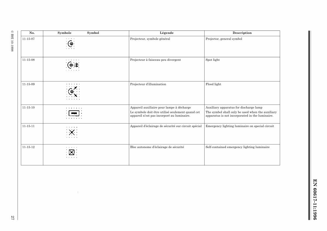
11-15-07 Projecteur, symbole général Projector, general symbol
11-15-08 Projecteur à faisceau peu divergent Spot light
11-15-09 Projecteur d’illumination Flood light
11-15-10 Appareil auxiliaire pour lampe à décharge
Le symbole doit être utilisé seulement quand cet appareil n’est pas incorporé au luminaire.
Auxiliary apparatus for discharge lamp
The symbol shall only be used when the auxiliary apparatus is not incorporated in the luminaire.
11-15-11 Appareil d’éclairage de sécurité sur circuit spécial Emergency lighting luminaire on special circuit
11-15-12 Bloc autonome d’éclairage de sécurité Self-contained emergency lighting luminaire
No. Symbole Symbol Légende Description

EN
60617-11:1996
28©
BS
I 10-1998
Section 16 — Appareils divers Section 16 — Miscellaneous
No. Symbole Symbol Légende Description
11-16-01 Chauffe-eau
Le symbole est représenté avec canalisation.
Water heater
The symbol is shown with wiring.
11-16-02 Ventilateur
Le symbole est représenté avec canalisation.
Fan
The symbol is shown with wiring.
11-16-03 Horloge de pointageEnregistreur horaire
Time clockTime recorder
11-16-04 Gâche électrique Electric lock
11-16-05 Interphone, par exemple portier audio d’immeuble Audio intercommunication equipment, for example an entry phone
EN
60617-11:1996
© B
SI 10-1998
29
Section 17 — Canalisations prefabriquées Section 17 — Trunking systems17.1 Les symboles de la présente section peuvent être utilisés pour montrer les
détails d’installation des:17.1 The symbols in this section may be used to show installation details of:
— enveloppes de chemins de câbles (tablettes) utilisées pour recevoir des conducteurs électriques ou
— enclosures of trays used to house electrical conductors or
— ensembles préfabriqués contenant des conducteurs électriques ou — prefabricated assemblies including electrical conductors or
— trajets de transmission spéciaux pour communications. — special communication transmission paths.
17.2 Des applications typiqus concement: 17.2 Typical applications are for:
— Les systèmes de distribution de puissance avec: — power distribution systems with:
• canalisations électriques réalisées sur place ou • site installed wiring or
• filerie et prises de courant installées en usines ou • factory installed wiring and outlets or
• canalisations préfabriquées, suivant la CEI 439-2; • factory-built busbar trunking systems (busways), according to
IEC 439-2;
— les goulottes, conduits ou chemins de câbles pour l’installation de: — installation channels, ducts or wireways for:
• circuits téléphoniques, • telephone circuits,
• systèmes de distribution pour diffusion TV, FM et radio, • TV, FM and radio broadcasting distribution systems,
• circuits de transmission de données, • data transmission circuits,
• systèmes de signalisation, • signalling systems,
• câbles souples coaxiaux et optiques; • flexible coaxial and fibre optic cables;
— les lignes coaxiales de transmission à fréquence radioélectrique; — coaxial radio-frequency transmission lines;
— les trajets de guides d’ondes. — waveguide runs.
EN
60617-11:1996
30©
BS
I 10-1998
No. Symbole Symbol Légende Description
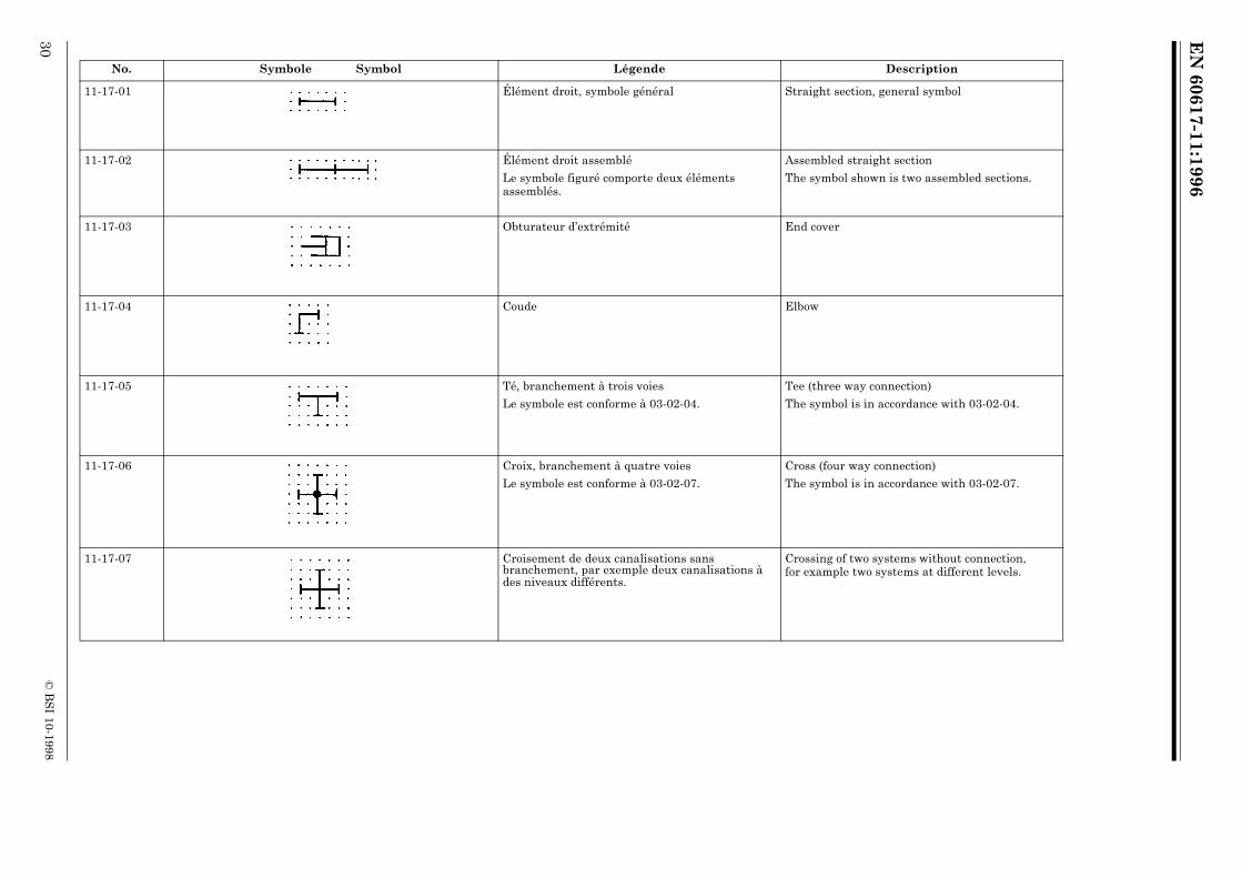
11-17-01 Élément droit, symbole général Straight section, general symbol
11-17-02 Élément droit assemblé
Le symbole figuré comporte deux éléments assemblés.
Assembled straight section
The symbol shown is two assembled sections.
11-17-03 Obturateur d’extrémité End cover
11-17-04 Coude Elbow
11-17-05 Té, branchement à trois voies
Le symbole est conforme à 03-02-04.
Tee (three way connection)
The symbol is in accordance with 03-02-04.
11-17-06 Croix, branchement à quatre voies
Le symbole est conforme à 03-02-07.
Cross (four way connection)
The symbol is in accordance with 03-02-07.
11-17-07 Croisement de deux canalisations sans branchement, par exemple deux canalisations à des niveaux différents.
Crossing of two systems without connection, for example two systems at different levels.
EN
60617-11:1996
© B
SI 10-1998
31
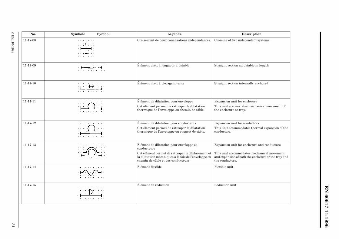
11-17-08 Croisement de deux canalisations indépendantes. Crossing of two independent systems.
11-17-09 Élément droit à longueur ajustable Straight section adjustable in length
11-17-10 Élément droit à blocage interne Straight section internally anchored
11-17-11 Élément de dilatation pour enveloppe
Cet élément permet de rattraper la dilatation thermique de l’enveloppe ou chemin de câble.
Expansion unit for enclosure
This unit accomodates mechanical movement of the enclosure or tray.
11-17-12 Élément de dilatation pour conducteurs
Cet élément permet de rattraper la dilatation thermique de l’enveloppe ou support de câble.
Expansion unit for conductors
This unit accommodates thermal expansion of the conductors.
11-17-13 Élément de dilatation pour enveloppe et conducteurs
Cet élément permet de rattraper le déplacement et la dilatation mécaniques à la fois de l’enveloppe ou chemin de câble et des conducteurs.
Expansion unit for enclosure and conductors
This unit accommodates mechanical movement and expansion of both the enclosure or the tray and the conductors.
11-17-14 Élément flexible Flexible unit
11-17-15 Élément de réduction Reduction unit
No. Symbole Symbol Légende Description
EN
60617-11:1996
32©
BS
I 10-1998
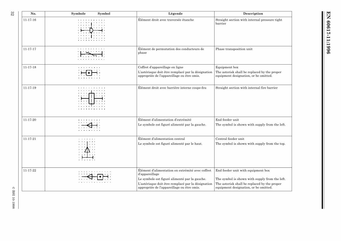
11-17-16 Élément droit avec traversée étanche Straight section with internal pressure tight barrier
11-17-17 Élément de permutation des conducteurs de phase
Phase transposition unit
11-17-18 Coffret d’appareillage en ligne
L’astérisque doit être remplacé par la désignation appropriée de l’appareillage ou être omis.
Equipment box
The asterisk shall be replaced by the proper equipment designation, or be omitted.
11-17-19 Élément droit avec barrière interne coupe-feu Straight section with internal fire barrier
11-17-20 Élément d’alimentation d’extrémité
Le symbole est figuré alimenté par la gauche.
End feeder unit
The symbol is shown with supply from the left.
11-17-21 Élément d’alimentation central
Le symbole est figuré alimenté par le haut.
Central feeder unit
The symbol is shown with supply from the top.
11-17-22 Élément d’alimentation en extrémité avec coffret d’appareillage
Le symbole est figuré alimenté par la gauche.
L’astérisque doit être remplacé par la désignation appropriée de l’appareillage ou être omis.
End feeder unit with equipment box
The symbol is shown with supply from the left.
The asterisk shall be replaced by the proper equipment designation, or be omitted.
No. Symbole Symbol Légende Description

EN
60617-11:1996
© B
SI 10-1998
33
11-17-23 Élément central d’alimentation avec coffret d’appareillage
Le symbole est figuré alimenté par le haut.
L’astérisque doit être remplacé par la désignation appropriée de l’appareillage ou être omis.
Central feeder unit with equipment box
The symbol is shown with supply from the top.
The asterisk shall be replaced by the proper equipment designation, or be omitted.
11-17-24 Élément droit avec dérivation fixe
Le symbole est figuré avec la dérivation vers le bas.
Straight section with fixed tap-off
The symbol is shown with tap-off downwards.
11-17-25 Élément droit avec plusieurs dérivations
Le symbole est figuré avec quatre dérivations, deux de chaque côté.
Straight section with several tap-offs
The symbol is shown with four tap-offs, two on each side.
11-17-26 Élément droit avec dérivation déplaçable de façon continue
Straight section with continously movable tap-off
11-17-27 Élément droit avec dérivation déplaçable par pas
Le symbole figuré comporte un pas de 1m.
Straight section with tap-off adjustable in steps
The symbol is shown with 1 meter steps.
11-17-28 Élément droit avec dérivation par contact mobile, par exemple contact glissant
Le symbole est conforme à 02-17-04.
Straight section with tap-off by movable contact, for example sliding contact
The symbol is in accordance with 02-17-04.
No. Symbole Symbol Légende Description

EN
60617-11:1996
34©
BS
I 10-1998
11-17-29 Élément droit avec dérivation fixe comprenant un coffret d’appareillage
L’astérisque doit être remplacé par la désignation appropriée de l’appareillage ou être omis.
Straight section with fixed tap-off with equipment box
The asterisk shall be replaced by the proper equipment designation, or be omitted.
11-17-30 Élément droit avec dérivation déplacable comprenant un coffret d’appareillage
L’astérisque droit être remplacé par la désignation appropriée de l’appareillage ou être omis.
Straight section with adjustable tap-off with equipment box
The asterisk shall be replaced by the proper equipment designation, or be omitted.
11-17-31 Élément droit avec dérivation fixe comprenant un socle de prise de courant, avec contact pour conducteur de protection.
Straight section with fixed tap-off having socket-outlet with protective contact.
11-17-32 Élément droit comprenant deux systèmes de canalisations, appelés dans ce symbole A et B
Straight section consisting of two wiring systems, in this symbol called A and B
11-17-33 Forme simpliféeSimplified form
11-17-34 Élément droit comprenant trois compartiments séparés
Le symbole est figuré avec trois compartiments, un pour le système de canalisations A, un pour le système de canalisations B et un disponible pour pose du câble C lors de l’installation.
Straight section consisting of three separate compartments
The symbol is shown with one compartment for wiring system A, one for wiring system B and one for on-site installation of cable C.
11-17-35 Forme simpliféeSimplified form
No. Symbole Symbol Légende Description
EN
60617-11:1996
© B
SI 10-1998
35
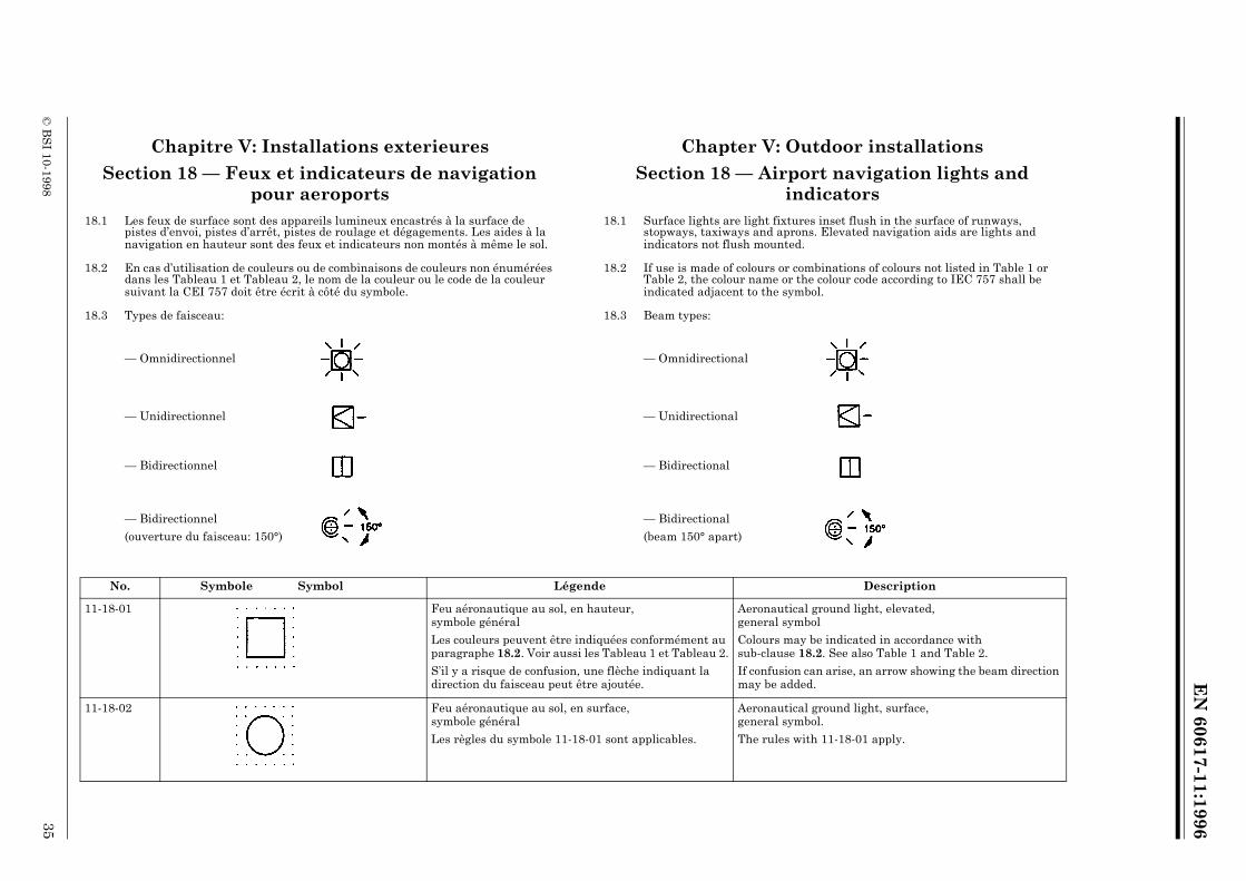
Chapitre V: Installations exterieures Chapter V: Outdoor installations
Section 18 — Feux et indicateurs de navigation pour aeroports
Section 18 — Airport navigation lights and indicators
18.1 Les feux de surface sont des appareils lumineux encastrés à la surface de pistes d’envoi, pistes d’arrêt, pistes de roulage et dégagements. Les aides à la navigation en hauteur sont des feux et indicateurs non montés à même le sol.
18.1 Surface lights are light fixtures inset flush in the surface of runways, stopways, taxiways and aprons. Elevated navigation aids are lights and indicators not flush mounted.
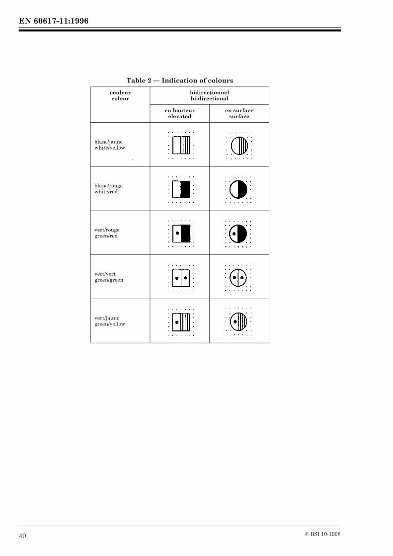
18.2 En cas d’utilisation de couleurs ou de combinaisons de couleurs non énumérées dans les Tableau 1 et Tableau 2, le nom de la couleur ou le code de la couleur suivant la CEI 757 doit être écrit à côté du symbole.
18.2 If use is made of colours or combinations of colours not listed in Table 1 or Table 2, the colour name or the colour code according to IEC 757 shall be indicated adjacent to the symbol.
18.3 Types de faisceau: 18.3 Beam types:
— Omnidirectionnel — Omnidirectional
— Unidirectionnel — Unidirectional
— Bidirectionnel — Bidirectional
— Bidirectionnel
(ouverture du faisceau: 150°)
— Bidirectional
(beam 150° apart)
No. Symbole Symbol Légende Description
11-18-01 Feu aéronautique au sol, en hauteur, symbole général
Les couleurs peuvent être indiquées conformément au paragraphe 18.2. Voir aussi les Tableau 1 et Tableau 2.
S’il y a risque de confusion, une flèche indiquant la direction du faisceau peut être ajoutée.
Aeronautical ground light, elevated, general symbol
Colours may be indicated in accordance with sub-clause 18.2. See also Table 1 and Table 2.
If confusion can arise, an arrow showing the beam direction may be added.
11-18-02 Feu aéronautique au sol, en surface, symbole général
Les règles du symbole 11-18-01 sont applicables.
Aeronautical ground light, surface, general symbol.
The rules with 11-18-01 apply.
EN
60617-11:1996
36©
BS
I 10-1998
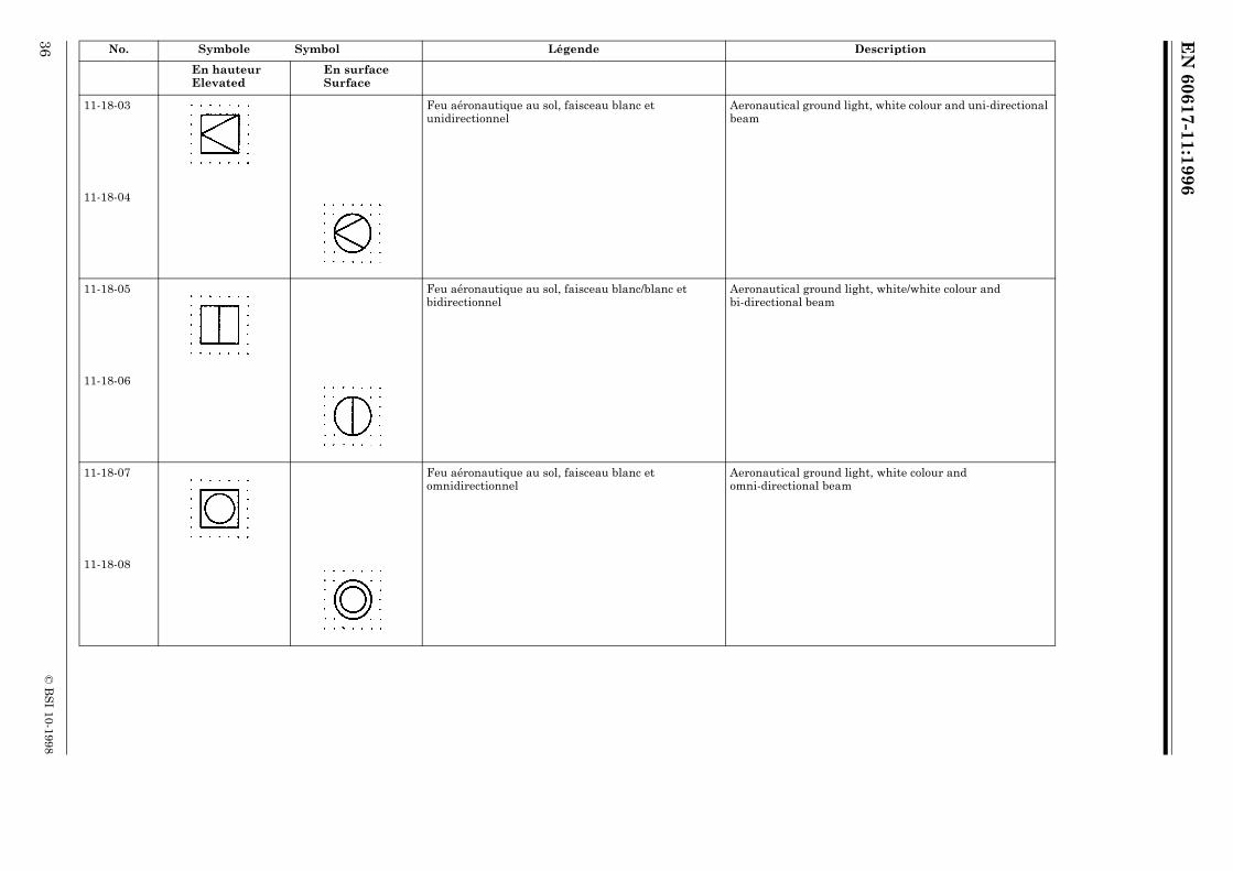
No. Symbole Symbol Légende Description
En hauteur Elevated
En surfaceSurface
11-18-03 Feu aéronautique au sol, faisceau blanc et unidirectionnel
Aeronautical ground light, white colour and uni-directional beam
11-18-04
11-18-05 Feu aéronautique au sol, faisceau blanc/blanc et bidirectionnel
Aeronautical ground light, white/white colour and bi-directional beam
11-18-06
11-18-07 Feu aéronautique au sol, faisceau blanc et omnidirectionnel
Aeronautical ground light, white colour and omni-directional beam
11-18-08

EN
60617-11:1996
© B
SI 10-1998
37
11-18-09 Feu de virage, faisceau vert/vert et bidirectionnel
Pour les couleurs, voir Tableau 1 et Tableau 2.
Curve light, green/green colour and bi-directional beam
For colours, see Table 1 and Table 2.
11-18-10 Feu de virage, faisceau blanc et unidirectionnel Curve light, white colour and uni-directional beam
11-18-11 Feu aéronautique au sol, faisceau omnidirectionnel blanc en haut et unidirectionnel blanc en bas
Aeronautical ground light, white omni-directional beam on top, and white uni-directional beam below
11-18-12 Feu aéronautique au sol, faisceau omnidirectionnel blanc en haut et bidirectionnel blanc/blanc en bas
Aeronautical ground light, white omni-directional beam on top, and white/white bi-directional beam below
11-18-13 Feu d’approche à éclats, faisceau unidirectionnel blanc Aeronautical ground light, white flashing uni-directional beam
11-18-14
No. Symbole Symbol Légende Description
En hauteur Elevated
En surfaceSurface

EN
60617-11:1996
38©
BS
I 10-1998
No. Symbole Symbol Légende Description
11-18-15 Indicateur de trajectoire d’approche de précision, faisceau unidirectionnel blanc/rouge
Precision approach path indicator white/red uni-directional beam
11-18-16 Indicateur de direction du vent Wind direction indicator
11-18-17 Indicateur de direction d’atterrissage Landing direction indicator
11-18-18 Feu d’obstacle,Feu de danger,faisceau omnidirectionnel, à éclats, rouge
Obstacle light,Hazard light,red flashing omni-directional beam
11-18-19 Feu aéronautique au sol,faisceau omnidirectionnel, à éclats, blanc
Aeronautical ground light,white flashing omni-directional beam
11-18-20 Plaque d’avertissement,Panneau de guidage,symbole général
Warning sign,Guidance sign,general symbol
11-18-21 EXEMPLES:
Plaque d’avertissement de distance: “4000/9000 pieds”
EXAMPLES:
Distance warning sign: “4000/9000 feet”
11-18-22 Panneau de guidage pour le roulage: “RAMP” Taxiing guidance sign: “RAMP”
EN 60617-11:1996
© BSI 10-1998 39
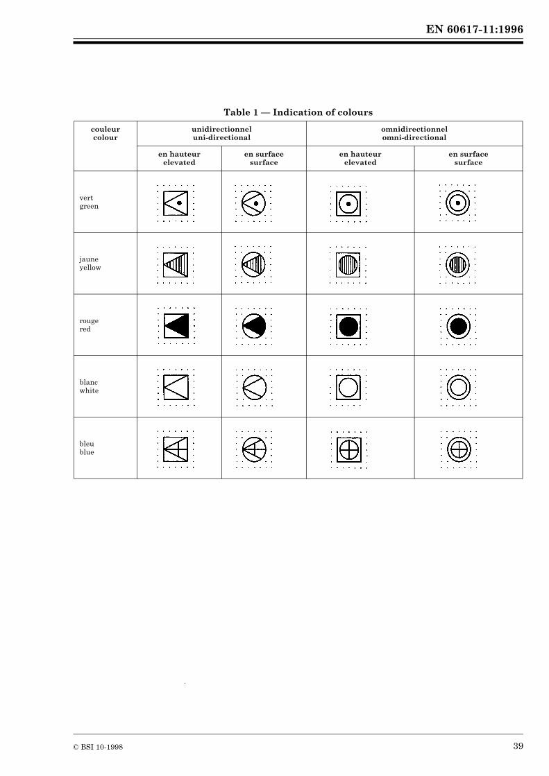
Table 1 — Indication of colours
couleur colour
unidirectionnel uni-directional
omnidirectionnel omni-directional
en hauteur elevated
en surface surface
en hauteur elevated
en surface surface
vert green
jaune yellow
rouge red
blanc white
bleu blue
EN 60617-11:1996
40 © BSI 10-1998
Table 2 — Indication of colours
couleur colour
bidirectionnel bi-directional
en hauteur elevated
en surface surface
blanc/jaune white/yellow
blanc/rouge white/red
vert/rouge green/red
vert/vert green/green
vert/jaune green/yellow
EN
60617-11:1996
© B
SI 10-1998
41
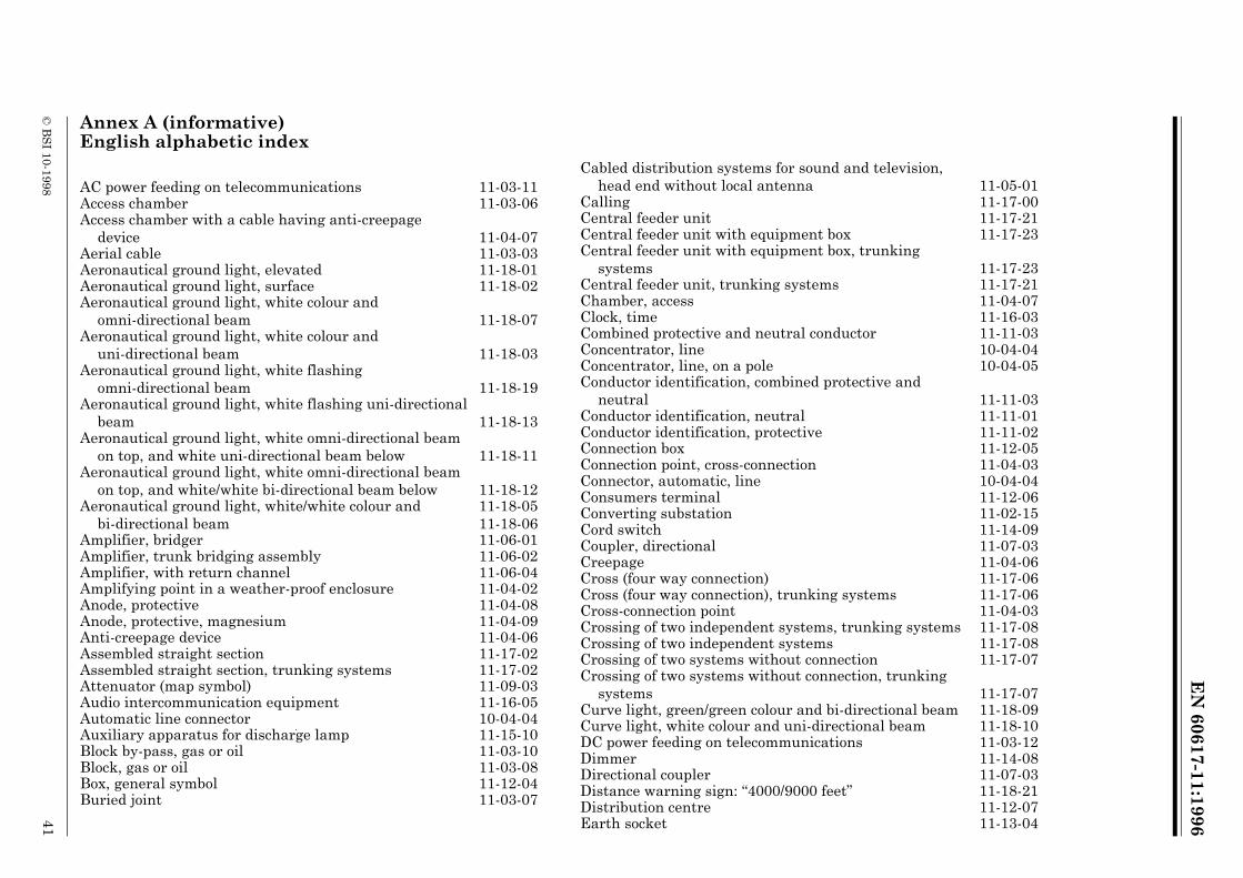
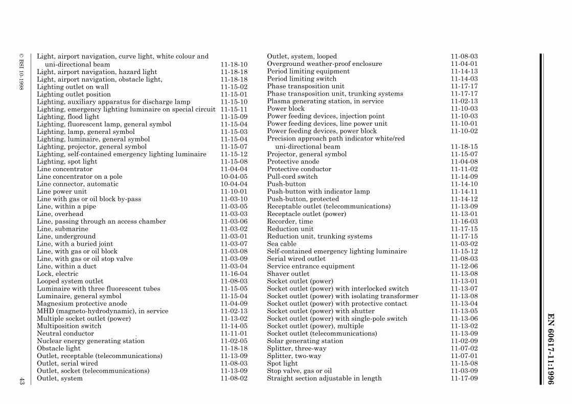
Annex A (informative) English alphabetic index
AC power feeding on telecommunications 11-03-11Access chamber 11-03-06Access chamber with a cable having anti-creepage
device 11-04-07Aerial cable 11-03-03Aeronautical ground light, elevated 11-18-01Aeronautical ground light, surface 11-18-02Aeronautical ground light, white colour and
omni-directional beam 11-18-07Aeronautical ground light, white colour and
uni-directional beam 11-18-03Aeronautical ground light, white flashing
omni-directional beam 11-18-19Aeronautical ground light, white flashing uni-directional
beam 11-18-13Aeronautical ground light, white omni-directional beam
on top, and white uni-directional beam below 11-18-11Aeronautical ground light, white omni-directional beam
on top, and white/white bi-directional beam below 11-18-12Aeronautical ground light, white/white colour and
bi-directional beam11-18-0511-18-06
Amplifier, bridger 11-06-01Amplifier, trunk bridging assembly 11-06-02Amplifier, with return channel 11-06-04Amplifying point in a weather-proof enclosure 11-04-02Anode, protective 11-04-08Anode, protective, magnesium 11-04-09Anti-creepage device 11-04-06Assembled straight section 11-17-02Assembled straight section, trunking systems 11-17-02Attenuator (map symbol) 11-09-03Audio intercommunication equipment 11-16-05Automatic line connector 10-04-04Auxiliary apparatus for discharge lamp 11-15-10Block by-pass, gas or oil 11-03-10Block, gas or oil 11-03-08Box, general symbol 11-12-04Buried joint 11-03-07
Cabled distribution systems for sound and television, head end without local antenna 11-05-01
Calling 11-17-00Central feeder unit 11-17-21Central feeder unit with equipment box 11-17-23Central feeder unit with equipment box, trunking
systems 11-17-23Central feeder unit, trunking systems 11-17-21Chamber, access 11-04-07Clock, time 11-16-03Combined protective and neutral conductor 11-11-03Concentrator, line 10-04-04Concentrator, line, on a pole 10-04-05Conductor identification, combined protective and
neutral 11-11-03Conductor identification, neutral 11-11-01Conductor identification, protective 11-11-02Connection box 11-12-05Connection point, cross-connection 11-04-03Connector, automatic, line 10-04-04Consumers terminal 11-12-06Converting substation 11-02-15Cord switch 11-14-09Coupler, directional 11-07-03Creepage 11-04-06Cross (four way connection) 11-17-06Cross (four way connection), trunking systems 11-17-06Cross-connection point 11-04-03Crossing of two independent systems, trunking systems 11-17-08Crossing of two independent systems 11-17-08Crossing of two systems without connection 11-17-07Crossing of two systems without connection, trunking
systems 11-17-07Curve light, green/green colour and bi-directional beam 11-18-09Curve light, white colour and uni-directional beam 11-18-10DC power feeding on telecommunications 11-03-12Dimmer 11-14-08Directional coupler 11-07-03Distance warning sign: “4000/9000 feet” 11-18-21Distribution centre 11-12-07Earth socket 11-13-04

EN
60617-11:1996
42©
BS
I 10-1998
Elbow 11-17-04Elbow, trunking systems 11-17-04Electric lock 11-16-04Emergency lighting luminaire on special circuit 11-15-11End cover 11-17-03End cover, trunking systems 11-17-03End feeder unit 11-17-20End feeder unit with equipment box 11-17-22End feeder unit with equipment box 11-17-22End feeder unit, trunking systems 11-17-20End of amplifier (branch or spur) 11-06-03Entry phone 11-16-05Equalizer 11-09-01Equalizer, variable 11-09-02Equipment box, trunking systems 11-17-18Equipment box 11-17-18Expansion unit for conductors 11-17-12Expansion unit for conductors, trunking systems 11-17-12Expansion unit for enclosure 11-17-11Expansion unit for enclosure and conductors 11-17-13Expansion unit for enclosure and conductors, trunking
systems 11-17-13Expansion unit for enclosure, trunking systems 11-17-11Fan 11-16-02Flexible unit 11-17-14Flexible unit, trunking systems 11-17-14Flood light 11-15-09Fluorescent lamp, general symbol 11-15-04Generating station 11-01-01Generating station, combined electric and heat 11-01-03Generating station, converting substation 11-02-15Generating station, geothermic 11-02-07Generating station, MHD (magneto-hydrodynamic) 11-02-13Generating station, nuclear energy 11-02-05Generating station, plasma 11-02-13Generating station, solar 11-02-09Generating station, thermoelectric 11-02-03Generating station, wind 11-02-11Generating stations, hydroelectric 11-02-01Geothermic generating station 11-02-07Guidance sign, general symbol 11-18-20Hazard light 11-18-18Head end with local antenna 11-05-01Head end without local antenna 11-05-02
Heater, water 11-16-01Indicator, airport navigation, distance warning
sign: “4000/9000 feet” 11-18-21Indicator, airport navigation, guidance sign, general
symbol 11-18-20Indicator, airport navigation, landing direction 11-18-17Indicator, airport navigation, precision approach path,
white/red uni-directional beam 11-18-15Indicator, airport navigation, taxiing guidance sign:
“RAMP” 11-18-22Indicator, airport navigation, warning sign, general
symbol 11-18-20Indicator, airport navigation, wind direction 11-18-16Injection point, power feeder 11-10-03Intercom 11-17-00Intermediate switch 11-14-07Junction box 11-12-05Key switch 11-13-07Key-operated switch 11-14-15Kiosk 11-05-00Lamp, general symbol 11-15-03Landing direction indicator 11-18-17Light, airport navigation, aeronautical ground light,
elevated, general symbol 11-18-01Light, airport navigation, aeronautical ground light,
surface, general symbol 11-18-02Light, airport navigation, aeronautical ground light,
white colour and uni-directional beam11-18-03 11-18-04
Light, airport navigation, aeronautical ground light, white flashing uni-directional beam
11-18-1311-18-14
Light, airport navigation, aeronautical ground light, white flashing omni-directional beam 11-18-19
Light, airport navigation, aeronautical ground light,white omni-directional beam on top, and white uni-directional beam below 11-18-11
Light, airport navigation, aeronautical ground light, white omni-directional beam on top, and white/white bi-directional beam below 11-18-12
Light, airport navigation, aeronautical ground light, white/white colour and bi-directional beam
11-18-05 11-18-06
Light, airport navigation, curve light, green/green colour and bi-directional beam 11-18-09
EN
60617-11:1996
© B
SI 10-1998
43
Light, airport navigation, curve light, white colour and uni-directional beam 11-18-10
Light, airport navigation, hazard light 11-18-18Light, airport navigation, obstacle light, 11-18-18Lighting outlet on wall 11-15-02Lighting outlet position 11-15-01Lighting, auxiliary apparatus for discharge lamp 11-15-10Lighting, emergency lighting luminaire on special circuit 11-15-11Lighting, flood light 11-15-09Lighting, fluorescent lamp, general symbol 11-15-04Lighting, lamp, general symbol 11-15-03Lighting, luminaire, general symbol 11-15-04Lighting, projector, general symbol 11-15-07Lighting, self-contained emergency lighting luminaire 11-15-12Lighting, spot light 11-15-08Line concentrator 11-04-04Line concentrator on a pole 10-04-05Line connector, automatic 10-04-04Line power unit 11-10-01Line with gas or oil block by-pass 11-03-10Line, within a pipe 11-03-05Line, overhead 11-03-03Line, passing through an access chamber 11-03-06Line, submarine 11-03-02Line, underground 11-03-01Line, with a buried joint 11-03-07Line, with gas or oil block 11-03-08Line, with gas or oil stop valve 11-03-09Line, within a duct 11-03-04Lock, electric 11-16-04Looped system outlet 11-08-03Luminaire with three fluorescent tubes 11-15-05Luminaire, general symbol 11-15-04Magnesium protective anode 11-04-09MHD (magneto-hydrodynamic), in service 11-02-13Multiple socket outlet (power) 11-13-02Multiposition switch 11-14-05Neutral conductor 11-11-01Nuclear energy generating station 11-02-05Obstacle light 11-18-18Outlet, receptable (telecommunications) 11-13-09Outlet, serial wired 11-08-03Outlet, socket (telecommunications) 11-13-09Outlet, system 11-08-02
Outlet, system, looped 11-08-03Overground weather-proof enclosure 11-04-01Period limiting equipment 11-14-13Period limiting switch 11-14-03Phase transposition unit 11-17-17Phase transposition unit, trunking systems 11-17-17Plasma generating station, in service 11-02-13Power block 11-10-03Power feeding devices, injection point 11-10-03Power feeding devices, line power unit 11-10-01Power feeding devices, power block 11-10-02Precision approach path indicator white/red
uni-directional beam 11-18-15Projector, general symbol 11-15-07Protective anode 11-04-08Protective conductor 11-11-02Pull-cord switch 11-14-09Push-button 11-14-10Push-button with indicator lamp 11-14-11Push-button, protected 11-14-12Receptable outlet (telecommunications) 11-13-09Receptacle outlet (power) 11-13-01Recorder, time 11-16-03Reduction unit 11-17-15Reduction unit, trunking systems 11-17-15Sea cable 11-03-02Self-contained emergency lighting luminaire 11-15-12Serial wired outlet 11-08-03Service entrance equipment 11-12-06Shaver outlet 11-13-08Socket outlet (power) 11-13-01Socket outlet (power) with interlocked switch 11-13-07Socket outlet (power) with isolating transformer 11-13-08Socket outlet (power) with protective contact 11-13-04Socket outlet (power) with shutter 11-13-05Socket outlet (power) with single-pole switch 11-13-06Socket outlet (power), multiple 11-13-02Socket outlet (telecommunications) 11-13-09Solar generating station 11-02-09Splitter, three-way 11-07-02Splitter, two-way 11-07-01Spot light 11-15-08Stop valve, gas or oil 11-03-09Straight section adjustable in length 11-17-09

EN
60617-11:1996
44©
BS
I 10-1998
Straight section adjustable in length, trunking systems 11-17-09Straight section consisting of three separate
compartments 11-17-34Straight section consisting of three separate
compartments 11-17-34Straight section consisting of three separate
compartments, simplified form 11-17-35Straight section consisting of three separate
compartments, simplified form, trunking systems 11-17-35Straight section consisting of two wiring systems 11-17-32Straight section consisting of two wiring systems,
simplified form 11-17-33Straight section consisting of two wiring systems,
simplified form, trunking systems 11-17-33Straight section consisting of two wiring systems,
trunking systems 11-17-32Straight section internally anchored 11-17-10Straight section internally anchored, trunking systems 11-17-10Straight section with adjustable tap-off with equipment
box 11-17-30Straight section with adjustable tap-off with equipment
box, trunking systems 11-17-30Straight section with continously movable tap-off 11-17-26Straight section with continously movable tap-off,
trunking systems 11-17-26Straight section with fixed tap-off 11-17-24Straight section with fixed tap-off having socket-outlet
with protective contact 11-17-31Straight section with fixed tap-off having socket-outlet
with protective contact, trunking systems 11-17-31Straight section with fixed tap-off with equipment box 11-17-29Straight section with fixed tap-off with equipment box,
trunking systems 11-17-29Straight section with fixed tap-off, trunking systems 11-17-24Straight section with internal fire barrier 11-17-19Straight section with internal fire barrier, trunking
systems 11-17-19Straight section with internal pressure tight barrier 11-17-16Straight section with internal pressure tight barrier,
trunking systems 11-17-16Straight section with several tap-offs 11-17-25Straight section with several tap-offs, trunking systems 11-17-25
Straight section with tap-off adjustable in steps 11-17-27Straight section with tap-off adjustable in steps,
trunking systems 11-17-27Straight section with tap-off by movable contact, for
example sliding contact 11-17-28Straight section with tap-off by movable contact, for
example sliding contact, trunking systems 11-17-28Straight section, general symbol 11-17-01Straight section, general symbol, trunking systems 11-17-01Submarine line 11-03-02Subscriber’s tap-off 11-08-01Substation 11-01-05Switch 11-14-01Switch with pilot light 11-14-02Switch, dimmer 11-14-08Switch, intermediate 11-14-07Switch, key-operated 11-14-15Switch, multiposition 11-14-05Switch, period limiting 11-14-03Switch, period limiting equipment 11-14-13Switch, pull-cord 11-14-09Switch, push-button 11-14-10Switch, push-button protected against unintentional
operation 11-14-12Switch, push-button with indicator lamp 11-14-11Switch, time 11-14-14Switch, timer 11-14-13Switch, two pole 11-14-04Switch, two-way 11-14-06Switch, watchman’s system device 11-14-15System outlet 11-08-02Tap-off, subscriber’s 11-08-01Taxiing guidance sign: “RAMP” 11-18-22Tee (three way connection) 11-17-05Tee (three way connection), trunking systems 11-17-05Thermoelectric generating station 11-02-03Three-phase wiring;neutral conductor and protective
conductor 11-11-04Time clock 11-16-03Time recorder 11-16-03Time switch 11-14-14Timer 11-14-13Trunking systems 11-17-00

EN
60617-11:1996
© B
SI 10-1998
45
Two pole switch 11-14-04Two-way switch 11-14-06Underground chamber 11-03-06Underground joint 11-03-07Underground line 11-03-01Variable equalizer 11-09-02Ventilator 11-16-02Warning sign, general symbol 11-18-20Watchman’s system device 11-14-15Water heater 11-16-01Weather-proof enclosure, overground weather 11-04-01Wind direction indicator 11-18-16Wind generating station 11-02-11Wiring box, general symbol 11-12-04Wiring connection box 11-12-05Wiring going downwards 11-12-02Wiring going upwards 11-12-01Wiring passing through vertically 11-12-03Wiring, consumers terminal 11-12-06Wiring, distribution centre 11-12-07Wiring, junction box 11-12-05Wiring, service entrance equipment 11-12-06

46 blank
BS EN 60617-11:1997
© BSI 10-1998
List of references
See national foreword.
BSI389 Chiswick High RoadLondonW4 4AL
|||||||||||||||||||||||||||||||||||||||||||||||||||||||||||||||||||||||||||||||||||||||||||||||||||||||||||||||||||||||||||||||
BSI Ð British Standards Institution
BSI is the independent national body responsible for preparing British Standards. Itpresents the UK view on standards in Europe and at the international level. It isincorporated by Royal Charter.
Revisions
British Standards are updated by amendment or revision. Users of British Standardsshould make sure that they possess the latest amendments or editions.
It is the constant aim of BSI to improve the quality of our products and services. Wewould be grateful if anyone finding an inaccuracy or ambiguity while using thisBritish Standard would inform the Secretary of the technical committee responsible,the identity of which can be found on the inside front cover. Tel: 020 8996 9000.Fax: 020 8996 7400.
BSI offers members an individual updating service called PLUS which ensures thatsubscribers automatically receive the latest editions of standards.
Buying standards
Orders for all BSI, international and foreign standards publications should beaddressed to Customer Services. Tel: 020 8996 9001. Fax: 020 8996 7001.
In response to orders for international standards, it is BSI policy to supply the BSIimplementation of those that have been published as British Standards, unlessotherwise requested.
Information on standards
BSI provides a wide range of information on national, European and internationalstandards through its Library and its Technical Help to Exporters Service. VariousBSI electronic information services are also available which give details on all itsproducts and services. Contact the Information Centre. Tel: 020 8996 7111.Fax: 020 8996 7048.
Subscribing members of BSI are kept up to date with standards developments andreceive substantial discounts on the purchase price of standards. For details ofthese and other benefits contact Membership Administration. Tel: 020 8996 7002.Fax: 020 8996 7001.
Copyright
Copyright subsists in all BSI publications. BSI also holds the copyright, in the UK, ofthe publications of the international standardization bodies. Except as permittedunder the Copyright, Designs and Patents Act 1988 no extract may be reproduced,stored in a retrieval system or transmitted in any form or by any means ± electronic,photocopying, recording or otherwise ± without prior written permission from BSI.
This does not preclude the free use, in the course of implementing the standard, ofnecessary details such as symbols, and size, type or grade designations. If thesedetails are to be used for any other purpose than implementation then the priorwritten permission of BSI must be obtained.
If permission is granted, the terms may include royalty payments or a licensingagreement. Details and advice can be obtained from the Copyright Manager.Tel: 020 8996 7070.