Graphical linkage synthesis 4 bar kinematic chain · Synthesis of slider crank mechanism Stavba...
35
Ing. Šimon Kovář, Ph.D. Graphical linkage synthesis 4 bar kinematic chain
Transcript of Graphical linkage synthesis 4 bar kinematic chain · Synthesis of slider crank mechanism Stavba...
Ing. Šimon Kovář, Ph.D.
Graphical linkage synthesis
4 bar kinematic chain

4 bar kinematic chain synthesis
Engaged: A1, A2, B1, B2
Detect: D1, D2, C1, C2
Choose: D0, C0

4 bar kinematic chain synthesis
Step 1.
connecting line A1 –A2, B1 – B2
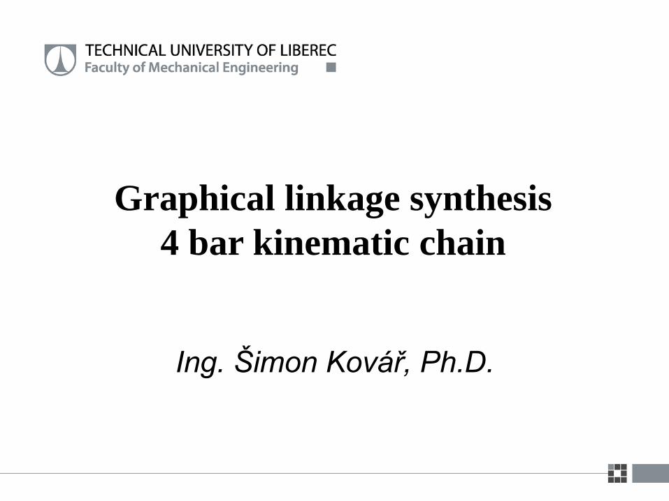
4 bar kinematic chain synthesis
Step 2.
symetrals a12, b12
Pole P12
Angle 12 /2
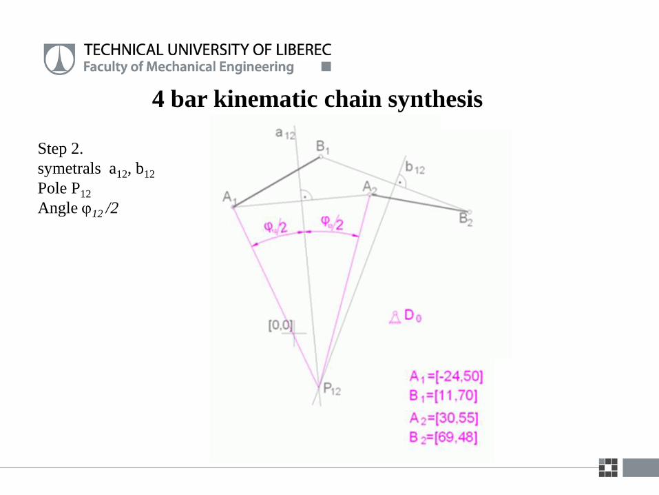
4 bar kinematic chain synthesis
Step 3.
Choose C0, D0
symetrals s1, s2
4 bar kinematic chain synthesis
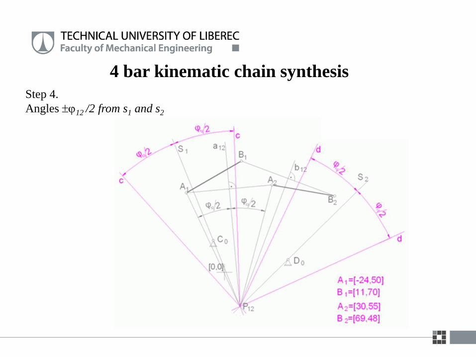
Step 4.
Angles 12 /2 from s1 and s2
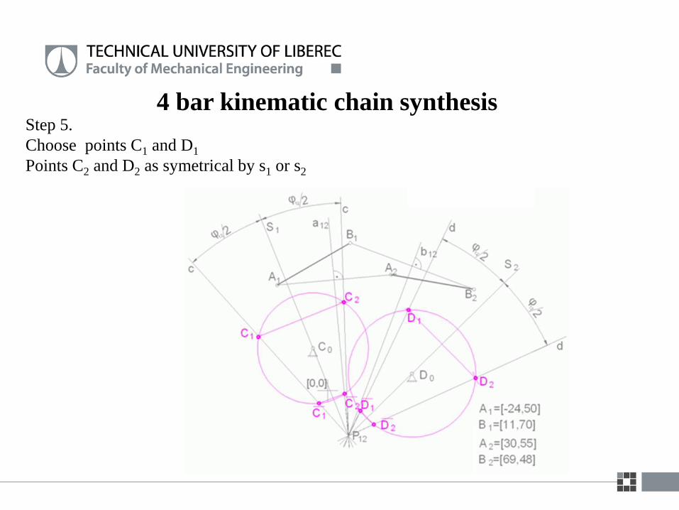
4 bar kinematic chain synthesisStep 5.
Choose points C1 and D1
Points C2 and D2 as symetrical by s1 or s2
4 bar kinematic chain synthesis
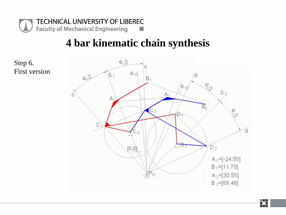
Step 6.
First version
4 bar kinematic chain synthesis
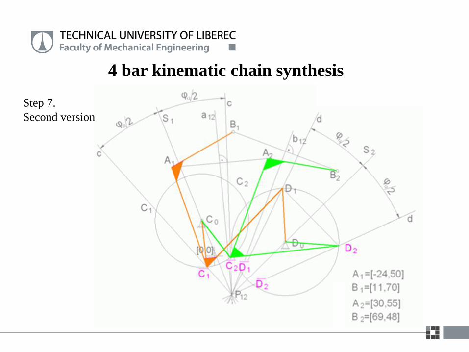
Step 7.
Second version
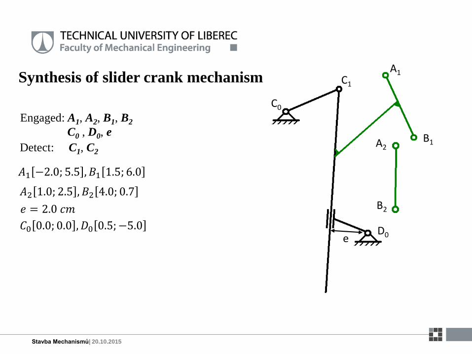
Synthesis of slider crank mechanism
𝐴1 −2.0; 5.5 , 𝐵1 1.5; 6.0
𝐴2 1.0; 2.5 , 𝐵2 4.0; 0.7
Stavba Mechanismů| 20.10.2015
A1
B1
C0
D0
C1
A2
B2
e
𝑒 = 2.0 𝑐𝑚
𝐶0 0.0; 0.0 , 𝐷0 0.5; −5.0
Engaged: A1, A2, B1, B2
C0 , D0, e
Detect: C1, C2
Synthesis of slider crank mechanism
Stavba Mechanismů| 20.10.2015
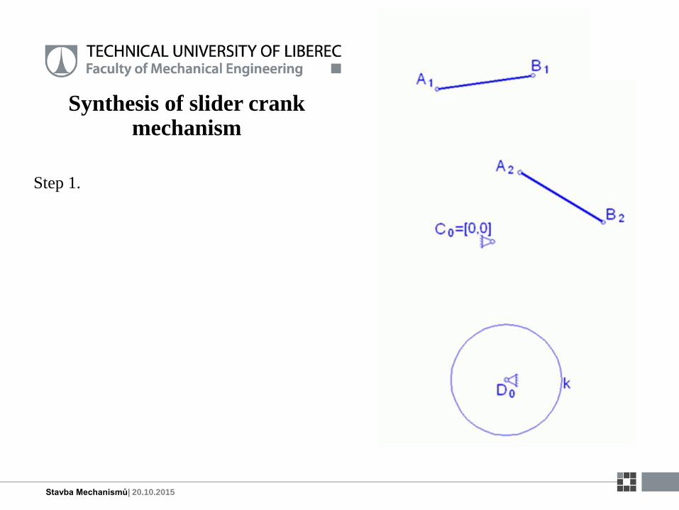
Step 1.
Synthesis of slider crank mechanism
Stavba Mechanismů| 20.10.2015
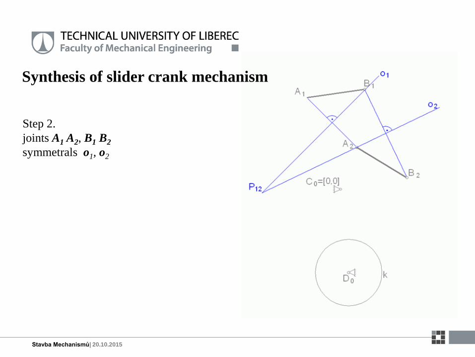
Step 2.
joints A1 A2, B1 B2
symmetrals o1, o2
Synthesis of slider crank mechanism
Stavba Mechanismů| 20.10.2015
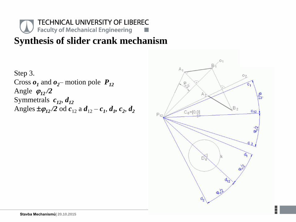
Step 3.
Cross o1 and o2– motion pole P12
Angle 12 /2
Symmetrals c12, d12
Angles 12 /2 od c12 a d12 – c1, d1, c2, d2
Synthesis of slider crank mechanism
Stavba Mechanismů| 20.10.2015
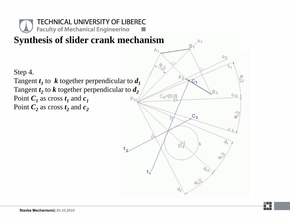
Step 4.
Tangent t1 to k together perpendicular to d1
Tangent t2 to k together perpendicular to d2
Point C1 as cross t1 and c1
Point C2 as cross t2 and c2
Synthesis of slider crank mechanism
Stavba Mechanismů| 20.10.2015
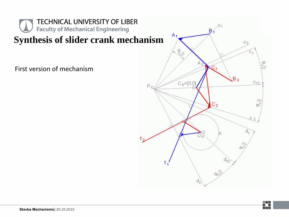
First version of mechanism

Synthesis of slider crank mechanism
Stavba Mechanismů| 20.10.2015
Second version of mechanism
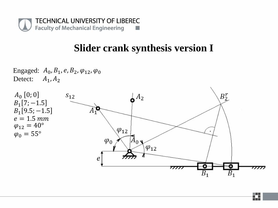
Slider crank synthesis version I
Engaged: 𝐴0, 𝐵1, 𝑒, 𝐵2, 𝜑12, 𝜑0
Detect: 𝐴1, 𝐴2
𝐴0 0; 0𝐵1 7;−1.5
𝑒 = 1.5 𝑚𝑚𝐵1 9.5; −1.5
𝜑12 = 40°𝜑0 = 55°

Slider crank synthesis version I
Result:
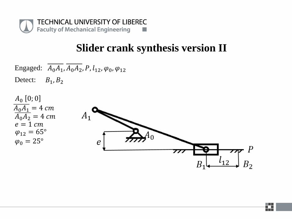
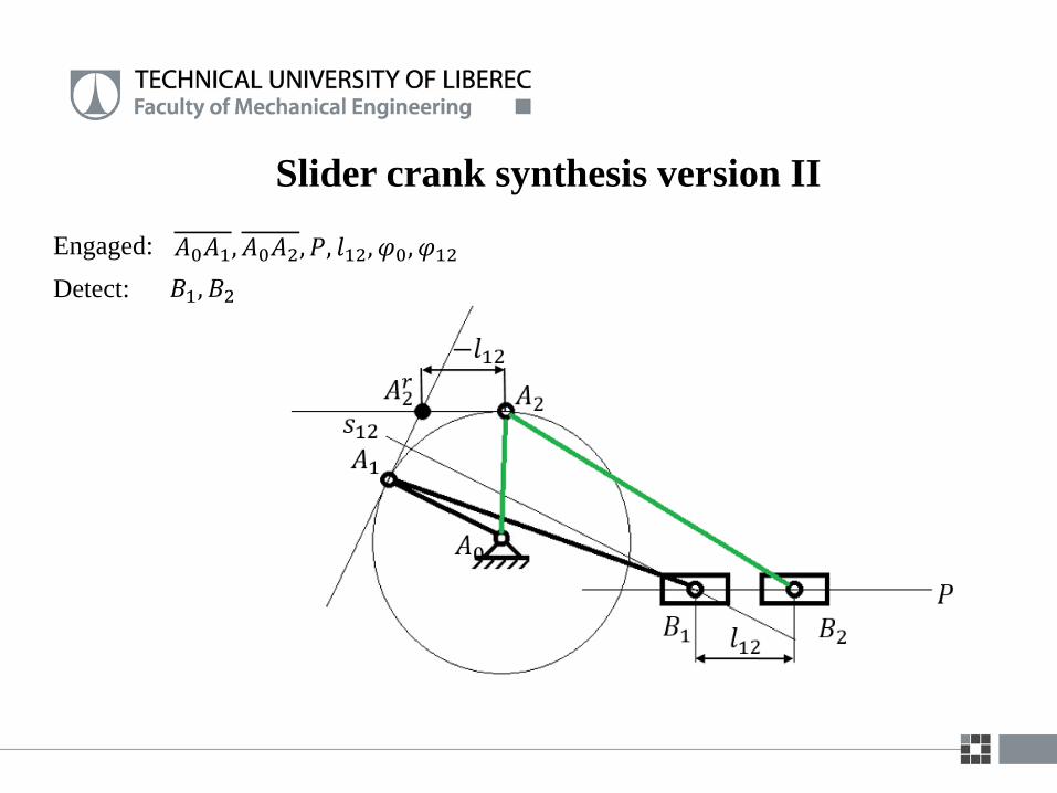
Slider crank synthesis version II
𝐴0𝐴1, 𝐴0𝐴2, 𝑃, 𝑙12, 𝜑0, 𝜑12
𝐵1, 𝐵2
Engaged:
Detect:
𝐴0 0; 0
𝑒 = 1 𝑐𝑚𝜑12 = 65°
𝜑0 = 25°
𝐴0𝐴1 = 4 𝑐𝑚𝐴0𝐴2 = 4 𝑐𝑚
Slider crank synthesis version II
𝐴0𝐴1, 𝐴0𝐴2, 𝑃, 𝑙12, 𝜑0, 𝜑12
𝐵1, 𝐵2
Engaged:
Detect:

Synthesis of 4 bar mechanism 2 prescribed
parallel positions of general member
Engaged:
C0 [0;0]
D0 [9;0]
A1 [3;8]
A2 [7;8]
= 45
rc = 3 cm
= 60
Detect:
C1 ,D1 , C2 , D2
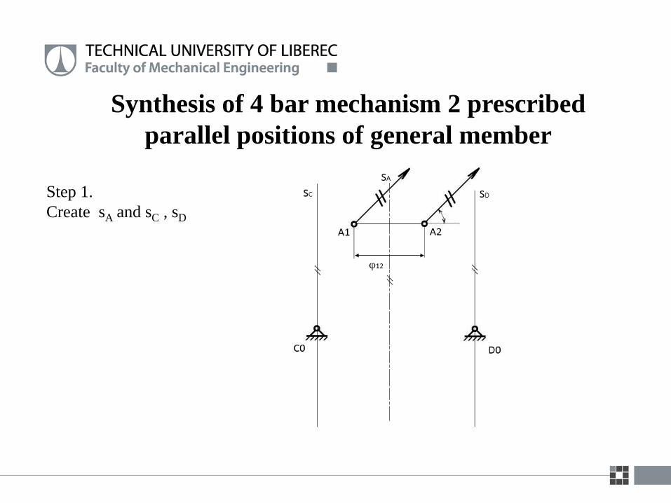
Synthesis of 4 bar mechanism 2 prescribed
parallel positions of general member
Step 1.
Create sA and sC , sD
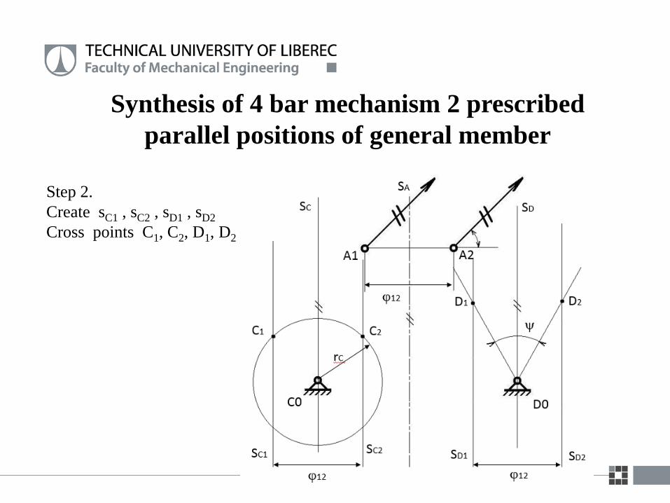
Synthesis of 4 bar mechanism 2 prescribed
parallel positions of general member
Step 2.
Create sC1 , sC2 , sD1 , sD2
Cross points C1, C2, D1, D2

Synthesis of 4 bar mechanism 2 prescribed
parallel positions of general member
Step 3.
Create sC1 , sC2 , sD1 , sD2
Cross points C1, C2, D1, D2
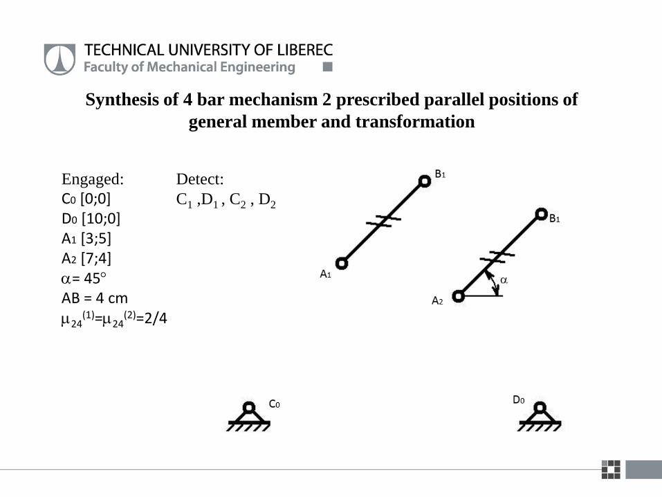
Synthesis of 4 bar mechanism 2 prescribed parallel positions of
general member and transformation
Engaged:
C0 [0;0]D0 [10;0]A1 [3;5]A2 [7;4]= 45AB = 4 cm24
(1)=24(2)=2/4
Detect:
C1 ,D1 , C2 , D2
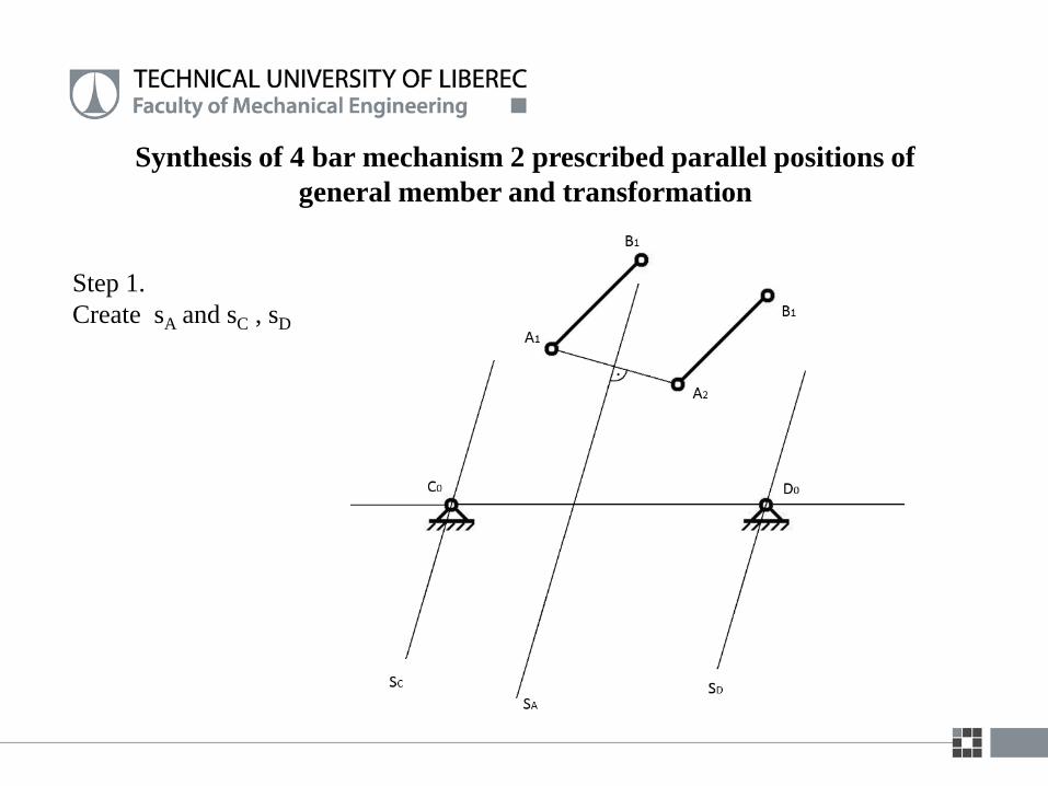
Synthesis of 4 bar mechanism 2 prescribed parallel positions of
general member and transformation
Step 1.
Create sA and sC , sD
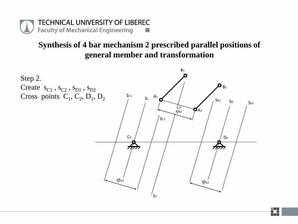
Synthesis of 4 bar mechanism 2 prescribed parallel positions of
general member and transformation
Step 2.
Create sC1 , sC2 , sD1 , sD2
Cross points C1, C2, D1, D2

Synthesis of 4 bar mechanism 2 prescribed parallel positions of
general member and transformation
Transformation
Definition of transformation
P42 42 = 43 + 32
42 = 41 +12
𝜇24(1)
=𝑥1
𝑥1 + 𝑑
𝜇24(2)
=𝑥2
𝑥2 + 𝑑
𝑥1 =𝜇24(1)
∙ 𝑑
1 − 𝜇24(1)
𝑥2 =𝜇24(2)
∙ 𝑑
1 − 𝜇24(2)
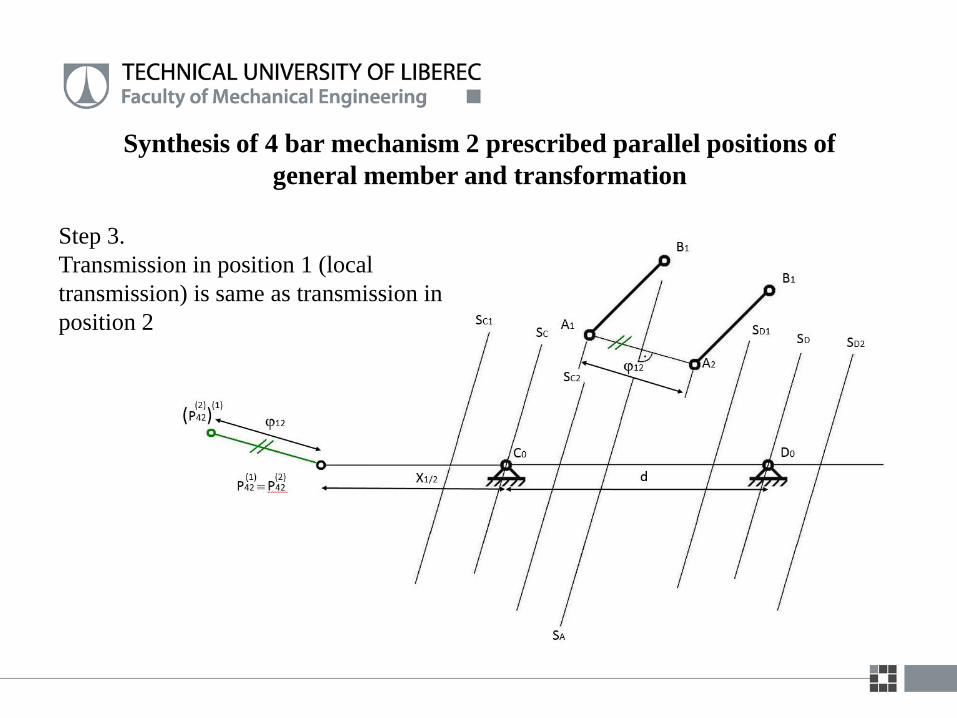
Synthesis of 4 bar mechanism 2 prescribed parallel positions of
general member and transformation
Step 3.
Transmission in position 1 (local
transmission) is same as transmission in
position 2
Synthesis of 4 bar mechanism 2 prescribed parallel positions of
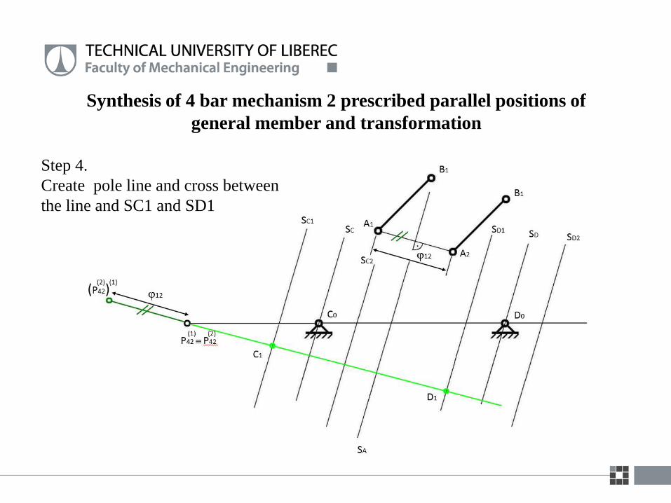
general member and transformation
Step 4.
Create pole line and cross between
the line and SC1 and SD1
Synthesis of 4 bar mechanism 2 prescribed parallel positions of
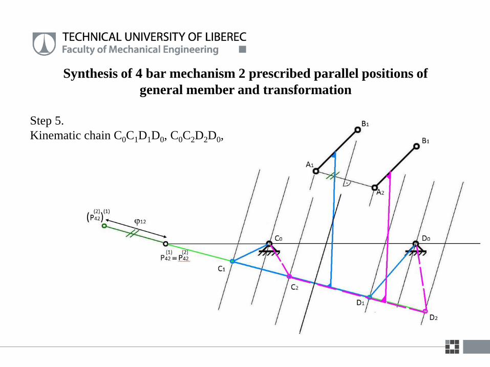
general member and transformation
Step 5.
Kinematic chain C0C1D1D0, C0C2D2D0,
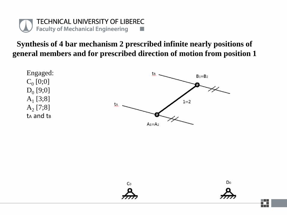
Synthesis of 4 bar mechanism 2 prescribed infinite nearly positions of
general members and for prescribed direction of motion from position 1
Engaged:
C0 [0;0]
D0 [9;0]
A1 [3;8]
A2 [7;8]
tA and tB
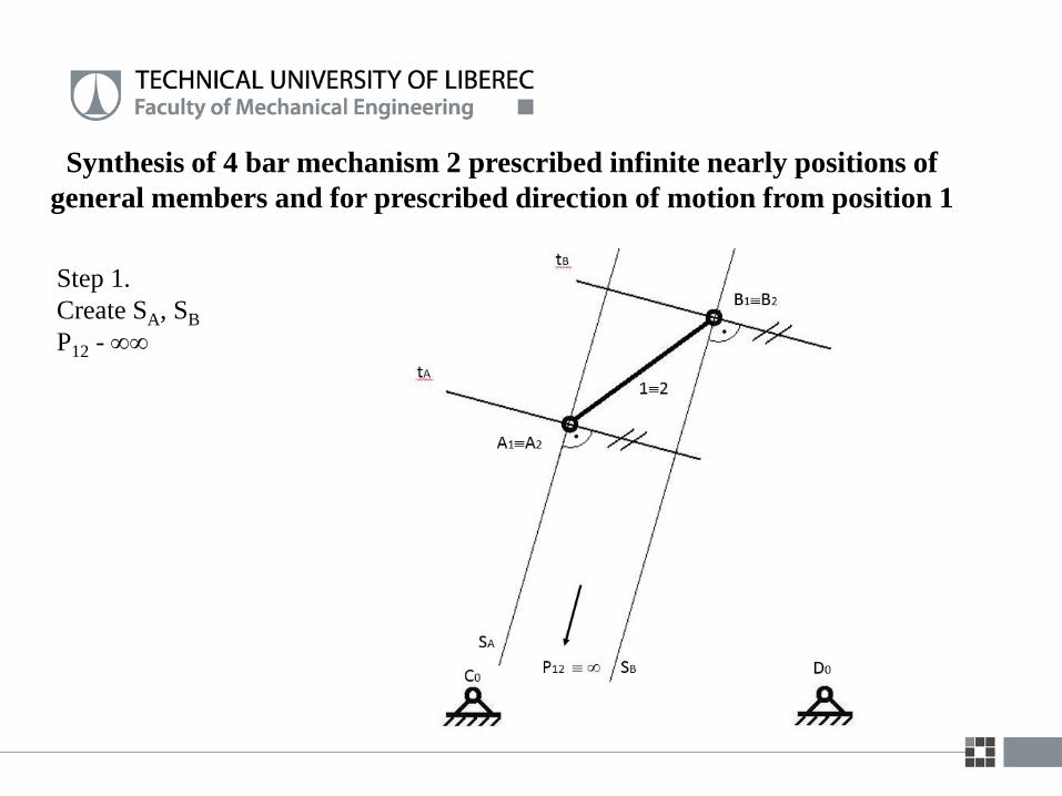
Synthesis of 4 bar mechanism 2 prescribed infinite nearly positions of
general members and for prescribed direction of motion from position 1
Step 1.
Create SA, SB
P12 -

Step 2.
Create SA
Create SC and SD
Synthesis of 4 bar mechanism 2 prescribed infinite nearly positions of
general members and for prescribed direction of motion from position 1
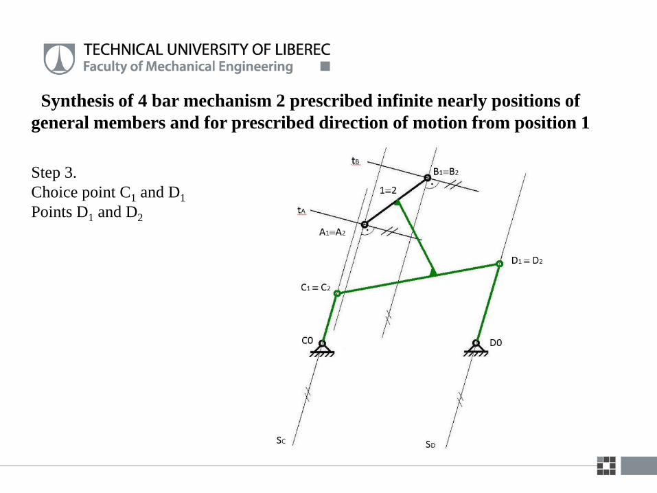
Step 3.
Choice point C1 and D1
Points D1 and D2
Synthesis of 4 bar mechanism 2 prescribed infinite nearly positions of
general members and for prescribed direction of motion from position 1