GRAPHICAL COMMUNICATION SYLLABUS FORM 1...
47
Graphical Communication 2009 1 GRAPHICAL COMMUNICATION SYLLABUS FORM 1 - FORM 5 The Syllabus has been drawn within the parameters of the S.E.C. 29 Syllabus for Graphical Communication 2008 - 2010. It would be advisable to check the S.E.C. syllabus at the beginning of each year and include any revisions, which may have taken place.
Transcript of GRAPHICAL COMMUNICATION SYLLABUS FORM 1...
Graphical Communication 2009 1
GRAPHICAL COMMUNICATION
SYLLABUS FORM 1 - FORM 5
The Syllabus has been drawn within the parameters of the S.E.C. 29 Syllabus for Graphical Communication 2008 - 2010. It would be advisable to check the S.E.C. syllabus at the beginning of each year and include any revisions, which may have taken place.
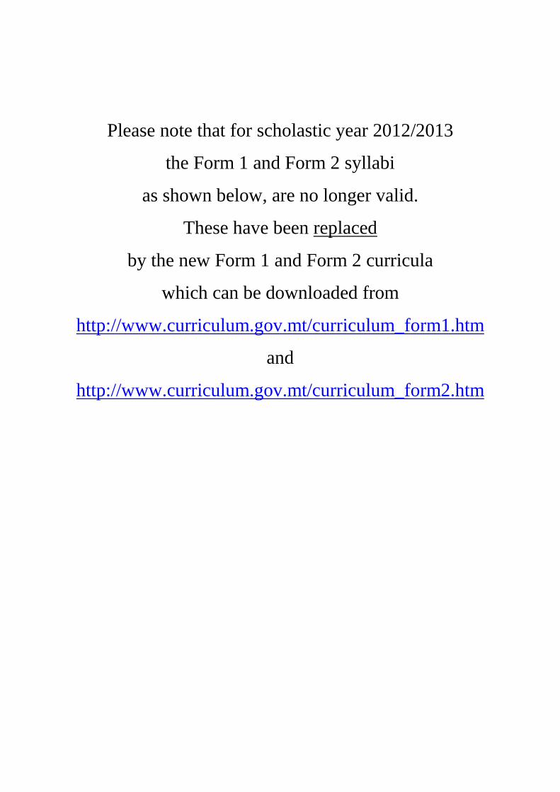
Please note that for scholastic year 2012/2013
the Form 1 and Form 2 syllabi
as shown below, are no longer valid.
These have been replaced
by the new Form 1 and Form 2 curricula
which can be downloaded from
http://www.curriculum.gov.mt/curriculum_form1.htm
and
http://www.curriculum.gov.mt/curriculum_form2.htm

Graphical Communication 2009 2
Graphical Communication 2009 3
Hereunder is the amended Graphical Communication
Syllabus as agreed to by the subject teachers who attended
the in-service course held in September 2006.
This syllabus, which is to be used in both the Junior Lyceums
and Area Secondary Schools, reflects the new S.E.C.
Examination for 2009-2010. Provisions for students who
choose the subject in the third year as an option are being
included.
C. SPITERI Education officer Design and Technology

Graphical Communication 2009 4
Graphical Communication 2009 5
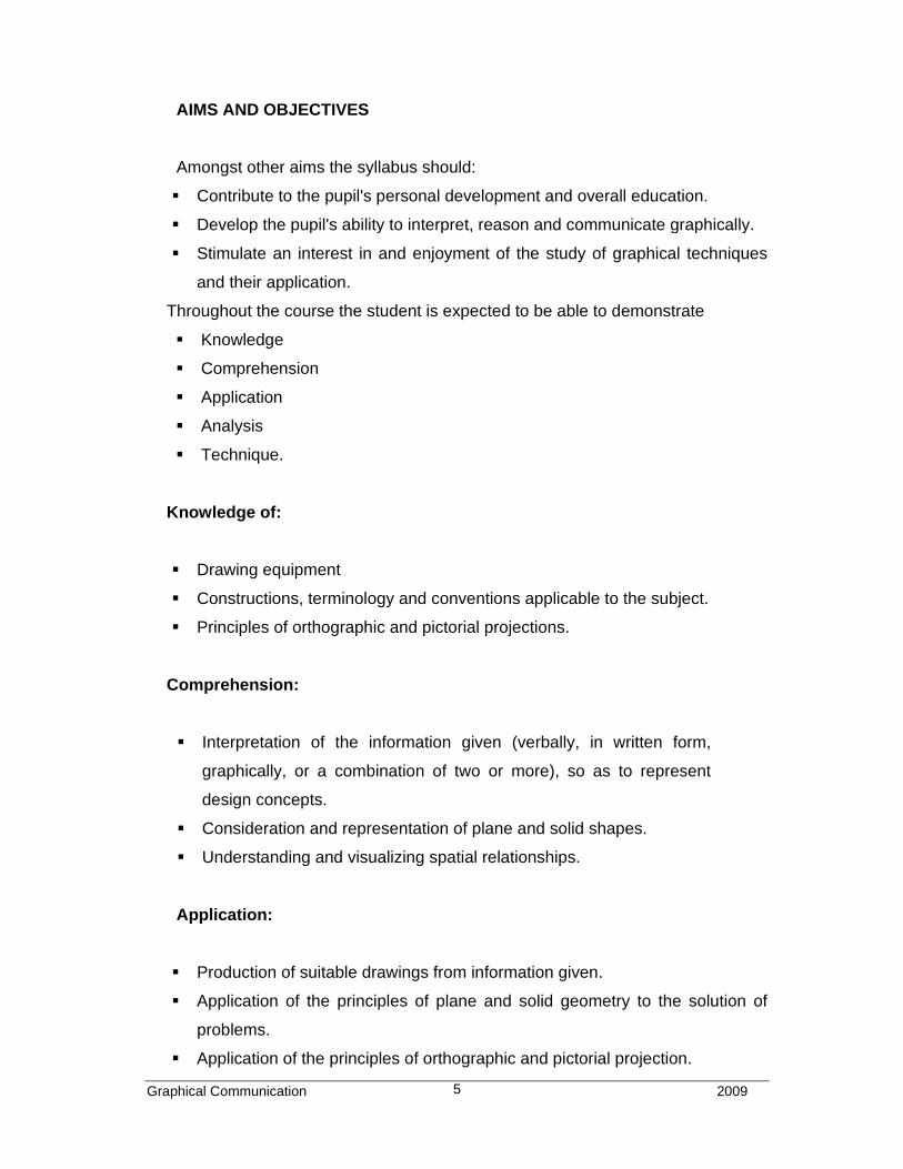
AIMS AND OBJECTIVES
Amongst other aims the syllabus should:
� Contribute to the pupil's personal development and overall education.
� Develop the pupil's ability to interpret, reason and communicate graphically.
� Stimulate an interest in and enjoyment of the study of graphical techniques
and their application.
Throughout the course the student is expected to be able to demonstrate
� Knowledge
� Comprehension
� Application
� Analysis
� Technique.
Knowledge of:
� Drawing equipment
� Constructions, terminology and conventions applicable to the subject.
� Principles of orthographic and pictorial projections.
Comprehension:
� Interpretation of the information given (verbally, in written form,
graphically, or a combination of two or more), so as to represent
design concepts.
� Consideration and representation of plane and solid shapes.
� Understanding and visualizing spatial relationships.
Application:
� Production of suitable drawings from information given.
� Application of the principles of plane and solid geometry to the solution of
problems.
� Application of the principles of orthographic and pictorial projection.
Graphical Communication 2009 6
Analysis:
� Comparison and use of the appropriate graphical methods of communicating
information and ideas.
� Analysis of and solutions to a problem graphically.
Technique:
� Accuracy in questions answered.
� Ability to sketch freehand and in good proportions.
� Presentation of good draughtsmanship (presentation, cleanliness, finishing,
spacing etc.)
� Use of available aids and media to enhance the presentation where
appropriate.
Note:
Neatness, presentation and accuracy should be stressed regularly
throughout the whole course. Technical terms and details should be used
when encountered
Graphical Communication 2009 17
FORM 3
Note: As you are aware students may opt to start Graphical Communication in
Form Three with the programme being covered in 3 years and in separate
classes as is being done in the case of foreign languages.
See appendix 1 at the end of syllabus.
Revision of Form 1and 2 syllabii. Problems and exercises.
1 GEOMETRICAL CONSTRUCTION:
1.1 The circle Circles touching; two and three circles touching;
internal and external; tangential arcs.
1.2 Triangles Construction of triangles from given data:
• Perimeter and the ratio of the 3 sides
• Perimeter and altitude of an isosceles triangle
• Perimeter and the 2 base angles
• Perimeter, base and base angle
• Base angle, apex angle and altitude
1.3 Tangents To a point on the circumference. From a point
outside the circle. Tangents to equal and unequal
circles (external and internal tangents).
1.4 Polygons General revision. Regular and irregular polygons
drawn from given data.
1.5 Division of lines Proportional division of lines. Its application in
drawing figures (e.g. Triangle with sides 2:4:5-
perimeter 200), etc.
Graphical Communication 2009 18
1.6 Enlargement Linear enlargement and reduction of regular or
irregular figures with straight lines only. Use of radial
method to a given measurement or ratio (see 1.4).
1.7 The ellipse Construction of the ellipse. Five methods: Auxiliary
circles or Concentric circles, Trammel, Intersecting
lines or Rectangle, Intersecting arcs or Foci or Radial
interceptors and Compasses or Approximate.
Construction of circles and lines tangential to the
ellipse.
2 ORTHOGRAPHIC PROJECTION:
2.1 Orthog. Proj. Further exercises regarding blocks with straight lines
only and including horizontal, vertical and inclined
lines/slopes, webs, ribs, etc. Blocks with hidden
edges and with square or rectangular holes.
Introducing curved lines, holes and centerlines.
Introducing 3rd angle orthographic projection. Both
projections should be used regularly.
Introducing the projection of the third view from the
given two elevations.
2.2 Sectioning Introducing simple whole sectioning. Section lines at
45° and equally spaced.
Graphical Communication 2009 19
3 SOLID GEOMETRY:
3.1 Prisms Square, rectangular, hexagonal, etc. truncated at
different angles - including elevations, true shape of
section and development. Truncation may be
sectioned.
3.2 The Cylinder Truncated at different angles and as 3.1
3.3 Pyramids Square, rectangular, hexagonal, etc. truncated at
different angles - including elevations, true shape of
section and development. Introducing true lengths.
3.4 The Cone Truncated at different angles and as 3.3.
3.5 Inclined Prisms and cylinders standing inclined at an angle to
one of the principal planes – to project the other two
elevations.
4 PICTORIAL PROJECTION:
4.1 Isometric Construction of isometric projections including circles
and arcs by the use of a grid, ordinates and
approximate (compasses) method.
4.2 Oblique Cabinet with straight and curved lines.
5 GRAPHICS
5.1 Logos Introduction to the three types of Logos:
Monogram (letters), Design, and Combination of
Monograms and Designs.
5.2 Ideograms Harder examples and exercises
Graphical Communication 2009 20
5.3 Graphs Introduction to. Line, bar, pie, block, pictographs,
percentage bar, etc. Keys / Legends and colour
coding.
Graphical Communication 2009 21
FORM 4
Revision - problems and exercises. Emphasis on time management.
1 GEOMETRICAL CONSTRUCTION:
1.1 Enlargement Linear enlargement and reduction of figures having
straight and curved lines. Different methods to be
used - radial, pole, proportional and grids.
1.2 Areas Conversion of areas. Polygon to quadrilateral,
triangle, rectangle, square. Rectangle to rectangle.
Rectangle to square, etc.
1.2 Areas Determination of areas of regular or irregular figures
bound by straight and curved lines. Both squares
and parts of and mid-ordinate methods are to be
used.
1.3 Loci Loci of simple moving parts/mechanisms. Circular
and reciprocating co-planar motion. Glissette,
Cranks, Cycloids, Involutes, Archimedean spiral and
Helix.
1.4 Helix To cover simple line helices with one or more
revolutions. Its application. Springs (circular,
rectangular or square). Handrails, etc. (threads not
considered.)
1.5 Scales Simple or plain scale and its application.
Graphical Communication 2009 22
2 SOLID GEOMETRY:
2.1 Conic sections The ellipse, the parabola and the hyperbola as conic
sections and using the radial and sections method.
Developments - radial method.
Projection of elevations from given
developments.
2.2 Inclined See Form 3: 3.5.
3 ORTHOGRAPHIC PROJECTION:
3.1 Assembly Orthographic projection of assembled components
from: in-line exploded pictorial projection, from
orthographic views, and combination of.
3.2 Sectioning Whole, half, part, staggered, removed, revolved.
3.3 Webs / Ribs Parts and features of parts not normally sectioned.
(i.e. Longitudinal cutting planes).
Webs, ribs, spokes, shafts and similar parts, cut
/sectioned along their axis are not to be shown in
section.
Parts and features of parts normally sectioned. (i.e.
transversal cutting planes). Webs, ribs
spokes, shafts, tubes and similar parts cut/sectioned
across their axis are to be shown in section.
3.4 Conventions Simple B.S. drawing conventions to represent
components in engineering drawing and including
dimensioning. Refer to PP 8888.
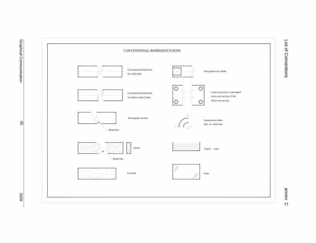
List of Conventions – annex C.
Graphical Communication 2009 23
3.5 Free hand Freehand sketching of orthographic views, with
straight and curved lines, in good proportion.
4 PICTORIAL PROJECTION:
4.1 Planometric Introduction to planometric projection. Horizontal axis
of the object to be 45° / 45° or 60° / 30°. In the case
of 45° / 45° the height may be reduced depending on
height of object. Including straight and curved lines.
4.2 Perspective Introduction to perspective projection. Estimated
only. Single-point and two points perspective.
Shading.
Worked example of a two point Perspective view - annex D
4.3 Free hand Freehand sketching of pictorial views with straight
and curved lines in good proportion and either
shaded or unshaded.
5 GRAPHICS :
5.1 Ideograms Harder examples. Past papers
5.2 Logos Harder examples. Past papers
5.3 Electricity Introduction to electrical circuits.
List of Electrical/Electronic symbols – annex E.
5.4 Graphs Harder examples. Past papers.
5.5 Flow Charts Simple flow charts of practical nature with symbols
for Terminals, Processes, Inputs / Outputs, Decisions
and Connectors.
Graphical Communication 2009 24
5.6 Computer Graphics The use of computer as an aid to draughting.
To follow a sequence of computer commands for
creating graphic images on a pre-printed grid and
draw images produced by a given programme.
Specimen question/answer – annex F.
5.7 Design. Design in relation to graphical presentation. To find
and draw a solution to a given simple problem in
design. See specimen paper S. E. C. 2002 -2005
syllabus.
Graphical Communication 2009 25
FORM 5
Revision as in previous years with emphasis on time management.
1 GEOMETRICAL CONSTRUCTIONS:
1.1 Scales Revision of the simple scale and introduction to
diagonal scales.
1.2 Vectors Simple vectors. Triangle and polygon of forces. Co-
planer and concurrent only.
2 SOLID GEOMETRY:
2.1 Interpenetration Interpenetration of solids. Lines of intersections,
between prisms and cylinders, equal and unequal in
diameter. Interpenetrations to be restricted to solids
whose axes are perpendicular. These axes may
either lie in the same vertical plane or offset, but
always parallel to the vertical plane. Developments.
3 ORTHOGRAPHIC PROJECTION:
3.1 Auxiliary Auxiliary views of simple objects. Auxiliary plan and
auxiliary elevation. Given auxiliary elevation and plan
to draw the front and side elevations.
3.2 Lines Lines in space. Finding their true length by rotation or
auxiliary projection. Lines to be drawn in isometric in
relation to the vertical and horizontal planes.
Graphical Communication 2009 26
4 GRAPHICS:
4.1 Ideograms Harder examples. Past papers.
4.2 Logos Harder examples. Past papers.
4.3 Electricity Harder examples. Past papers.
4.4 Computer Graphics Harder examples.
4.5 Charts Sequence of work. (as in Do-it-Yourself Kits)
4.6 Design See Form 4 : 5.7.
Revision of work through past papers with emphasis on accuracy,
presentation and time management.
Graphical Communication 2009 27
APPENDIX 1
GRAPHICAL COMMUNICATION - Taken as a third-year option.
FORM 3 year 1
1 THE EQUIPMENT:
1.1 Pencils Types of pencils, common and clutch. Codes used
on pencils (6H----H HB B---6B). Pencils used in the
subject. Sharpening of pencils. Pencil point should
always be sharp for accuracy, neatness and
presentation.
1.2 Erasers Types of. Synthetic and natural rubber, soft and
hard.
1.3 Rulers Common types: wooden, plastic (metal should not be
used). Attention when measuring to avoid errors.
1.4 Paper Types of: Grading by weight and surface finish.
Common metric sizes: A sizes.
1.5 Drawing boards Types of boards: wooden or plastic used by students
and drafting machines used in drawing offices. Sizes.
1.6 Board clips Their use and alternatives. Drafting tape or sellotape,
pins, other fasteners.
1.7 Tee-square Wooden or plastic. Fixed or adjustable. Sizes.
Graphical Communication 2009 28
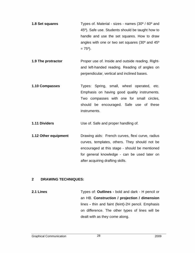
1.8 Set squares Types of. Material - sizes - names (30º / 60º and
45º). Safe use. Students should be taught how to
handle and use the set squares. How to draw
angles with one or two set squares (30º and 45º
= 75º).
1.9 The protractor Proper use of. Inside and outside reading. Right-
and left-handed reading. Reading of angles on
perpendicular, vertical and inclined bases.
1.10 Compasses Types: Spring, small, wheel operated, etc.
Emphasis on having good quality instruments.
Two compasses with one for small circles,
should be encouraged. Safe use of these
instruments.
1.11 Dividers Use of. Safe and proper handling of.
1.12 Other equipment Drawing aids: French curves, flexi curve, radius
curves, templates, others. They should not be
encouraged at this stage - should be mentioned
for general knowledge - can be used later on
after acquiring drafting skills.
2 DRAWING TECHNIQUES:
2.1 Lines Types of: Outlines - bold and dark - H pencil or
an HB. Construction / projection / dimension
lines - thin and faint (feint)-2H pencil. Emphasis
on difference. The other types of lines will be
dealt with as they come along.
Graphical Communication 2009 29
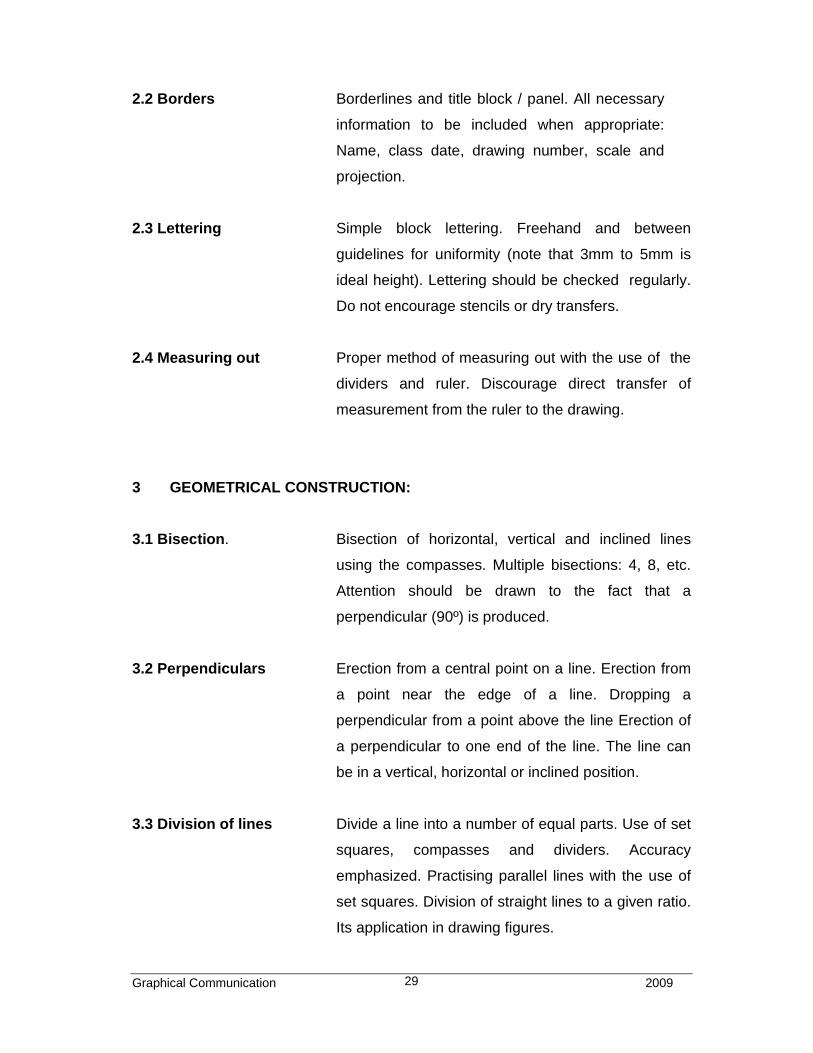
2.2 Borders Borderlines and title block / panel. All necessary
information to be included when appropriate:
Name, class date, drawing number, scale and
projection.
2.3 Lettering Simple block lettering. Freehand and between
guidelines for uniformity (note that 3mm to 5mm is
ideal height). Lettering should be checked regularly.
Do not encourage stencils or dry transfers.
2.4 Measuring out Proper method of measuring out with the use of the
dividers and ruler. Discourage direct transfer of
measurement from the ruler to the drawing.
3 GEOMETRICAL CONSTRUCTION:
3.1 Bisection. Bisection of horizontal, vertical and inclined lines
using the compasses. Multiple bisections: 4, 8, etc.
Attention should be drawn to the fact that a
perpendicular (90º) is produced.
3.2 Perpendiculars Erection from a central point on a line. Erection from
a point near the edge of a line. Dropping a
perpendicular from a point above the line Erection of
a perpendicular to one end of the line. The line can
be in a vertical, horizontal or inclined position.
3.3 Division of lines Divide a line into a number of equal parts. Use of set
squares, compasses and dividers. Accuracy
emphasized. Practising parallel lines with the use of
set squares. Division of straight lines to a given ratio.
Its application in drawing figures.
Graphical Communication 2009 30
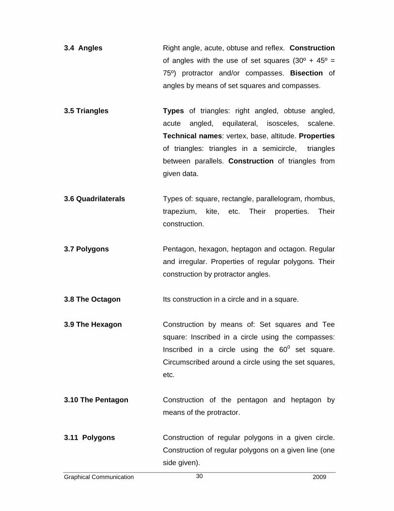
3.4 Angles Right angle, acute, obtuse and reflex. Construction
of angles with the use of set squares (30º + 45º =
75º) protractor and/or compasses. Bisection of
angles by means of set squares and compasses.
3.5 Triangles Types of triangles: right angled, obtuse angled,
acute angled, equilateral, isosceles, scalene.
Technical names: vertex, base, altitude. Properties
of triangles: triangles in a semicircle, triangles
between parallels. Construction of triangles from
given data.
3.6 Quadrilaterals Types of: square, rectangle, parallelogram, rhombus,
trapezium, kite, etc. Their properties. Their
construction.
3.7 Polygons Pentagon, hexagon, heptagon and octagon. Regular
and irregular. Properties of regular polygons. Their
construction by protractor angles.
3.8 The Octagon Its construction in a circle and in a square.
3.9 The Hexagon Construction by means of: Set squares and Tee
square: Inscribed in a circle using the compasses:
Inscribed in a circle using the 600 set square.
Circumscribed around a circle using the set squares,
etc.
3.10 The Pentagon Construction of the pentagon and heptagon by
means of the protractor.
3.11 Polygons Construction of regular polygons in a given circle.
Construction of regular polygons on a given line (one
side given).
Graphical Communication 2009 31
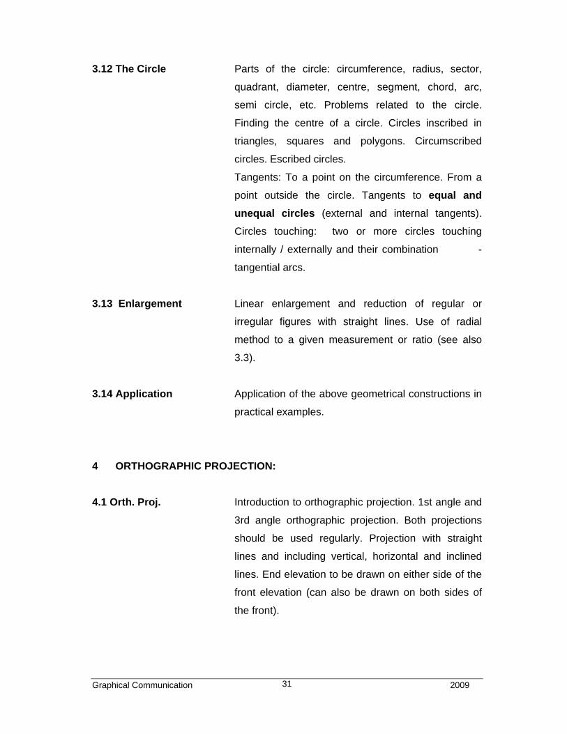
3.12 The Circle Parts of the circle: circumference, radius, sector,
quadrant, diameter, centre, segment, chord, arc,
semi circle, etc. Problems related to the circle.
Finding the centre of a circle. Circles inscribed in
triangles, squares and polygons. Circumscribed
circles. Escribed circles.
Tangents: To a point on the circumference. From a
point outside the circle. Tangents to equal and
unequal circles (external and internal tangents).
Circles touching: two or more circles touching
internally / externally and their combination -
tangential arcs.
3.13 Enlargement Linear enlargement and reduction of regular or
irregular figures with straight lines. Use of radial
method to a given measurement or ratio (see also
3.3).
3.14 Application Application of the above geometrical constructions in
practical examples.
4 ORTHOGRAPHIC PROJECTION:
4.1 Orth. Proj. Introduction to orthographic projection. 1st angle and
3rd angle orthographic projection. Both projections
should be used regularly. Projection with straight
lines and including vertical, horizontal and inclined
lines. End elevation to be drawn on either side of the
front elevation (can also be drawn on both sides of
the front).
Graphical Communication 2009 32
4.2 Hidden details Blocks with hidden edges (dotted lines) drawn
according to the B.S., slots and square/rectangular
holes. Introducing curved lines, holes and
centrelines.
4.3 Sectioning Introducing simple whole sectioning. Section lines at
45º and equally spaced.
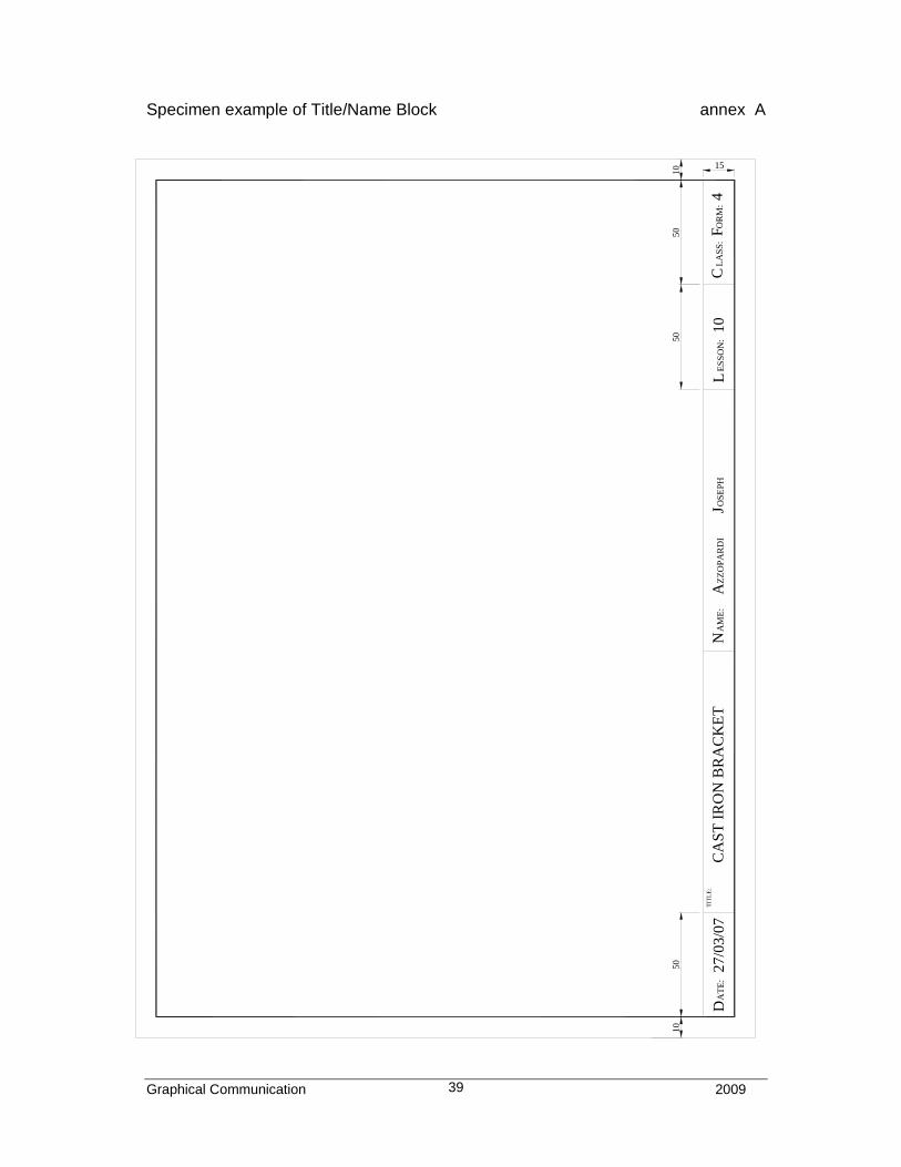
Specimen example of a Name/Title Block – annex A.
4.4 Free-hand Free-hand sketches of elevations on squared (grid)
paper. Several examples can be given where two
views are given and the third is to be added.
Enlargement of figures / drawings using grids.
5 SOLID GEOMETRY:
5.1 Prisms Square, rectangular, hexagonal, etc. truncated at
different angles and including elevations. True shape
of section and development (fold lines). Truncation
may be sectioned.
5.2 The Cylinder Truncated at different angles and as in 5.1
5.3 Pyramids Square, rectangular, hexagonal, etc. truncated at
different angles and including: elevations, true
shape of section and development. Introducing true
lengths.
5.4 The Cone Truncated at different angles and as in 5.3.
5.5 Inclined Prisms and cylinders standing inclined at an angle to
one of the principal planes. To project side elevation
and plan.
Graphical Communication 2009 33
6 PICTORIAL PROJECTION:
6.1 Isometric Projection Introduction. Straight lines, including vertical,
horizontal and inclined. To be drawn from given
isometric, oblique and simple orthographic views.
Curved lines including circles, arcs and cylinders.
Use of grid, ordinates and approximate (compasses)
method
6.2 Oblique Projection Introduction. Similar to 6.1. To be in CABINET form
with the 3rd axis at 45º and half true length.
CAVALIER oblique to be mentioned for general
knowledge only.

Graphical Communication 2009 34
Graphical Communication 2009 35
FORM 4 year 2
1 GEOMETRICAL CONSTRUCTION:
1.1 The Ellipse Construction of the ellipse. Five methods - Auxiliary
circles or Concentric circles, Trammel, Intersecting
lines or Rectangle, Intersecting arcs or Foci or Radial
interceptors and Compasses or Approximate.
Construction of lines and circles tangential to the
ellipse.
1.2 Loci Loci of simple moving parts/mechanisms. Circular
and reciprocating co-planar motion. Glissette,
Cranks, Cycloids, Involutes, Archimedean spiral and
Helix.
1.3 Helix To cover simple line helices with one or more
revolutions. Its applications such as Springs -
circular, rectangular or square. Other applications
(threads not considered).
1.4 Scales Simple or plain scale. Its application.
1.5 Enlargement Linear enlargement and reduction of figures having
straight and curved lines. Different methods to be
used: radial, pole, proportional, etc.
1.6 Areas Conversion of areas. Polygon to quadrilateral,
triangle, rectangle, square. Rectangle to rectangle.
Rectangle to square etc.
Graphical Communication 2009 36
1.7 Areas Determination of areas of regular or irregular figures
bound by straight and curved lines. Both methods -
squares and parts of - and mid-ordinate, methods are
to be used.
2 SOLID GEOMETRY:
2.1 Conic sections The ellipse, the parabola and the hyperbola as conic
sections and using radial and sections method.
Developments - radial method. Projection of
elevations from given developments.
2.2 Inclined See Form 3 Year 1: 5.5
3 ORTHOGRAPHIC PROJECTION:
3.1 Assembly Orthographic projection of assembled components
from: in line exploded pictorial projection. From
orthographic views and combination of.
3.2 Sectioning Whole, half, part, staggered, removed, revolved.
3.3 Webs / Ribs Parts and features of parts not normally
sectioned. (i.e. longitudinal cutting planes).
Webs, ribs, spokes, shafts and similar parts,
cut/sectioned along their axis are not to be
shown in section.
Parts and features of parts normally sectioned.
(i.e. transversal cutting planes). Webs, ribs,
spokes, shafts and similar parts sectioned across
their axis are to be shown in section.
Graphical Communication 2009 37
3.4 Conventions Simple B.S. drawing conventions to represent
components in engineering drawing. Dimensioning
included. Refer to PP8888.
List of commonly used Conventions – annex C.
3.5 Free-hand Free-hand sketching of orthographic views with
straight and curved lines in good proportion.
4 PICTORIAL PROJECTION:
4.1 Planometric Introduction to planometric projection. Horizontal axis
of the object to be 45° / 45° or 60° / 30°. In the case
of 45° /45° the height may be reduced, depending on
height of object. Including straight and curved lines.
4.2 Perspective Introduction to perspective projection. Estimated
only. Single point and two points perspective.
Shading.
4.3 Free hand Free-hand sketching of pictorial views with straight
and curved lines in good proportion and either
shaded or unshaded.
5 GRAPHICS:
5.1 Ideograms Introduction and examples of.
List of safety signs – annex E.
5.2 Logos Introduction and examples of.
5.3 Electricity Introduction to electrical circuits and examples of.
List of Electrical/Electronic symbols – annex E.
Graphical Communication 2009 38
5.4 Graphs Line, block , pie, pictograms, etc.
5.5 Flow Charts Simple Flow Charts of practical nature. Symbols
used - terminals, process, input / output, decisions
and connectors.
5.6 Computer Graphics The use of computer as an aid to draughting. To
follow a sequence of computer commands for
creating graphic images on a pre-printed grid and
draw images produced by a given programme.
Specimen question/answer – annex F.
5.7 Design Design in relation to graphical presentation. To find
and draw a solution to a given simple problem in
design. See specimen paper SEC 2002 -2005
syllabus.
THE SYLLABUS FOR FORM 5 REMAINS THE SAME.
Graphical Communication 2009 39
L
50
CA
ST
IRO
N B
RA
CK
ET
27/
03/0
7
50
AT
E:
D
10
TIT
LE
:
ZZ
OP
AR
DI
AN
AM
E:
J OS
EP
H
50
LAS
S:
CO
RM
:F
410
ES
SO
N:
15
10
Specimen example of Title/Name Block annex A

Graphical Communication 2009 40
Graphical Communication 2009 41
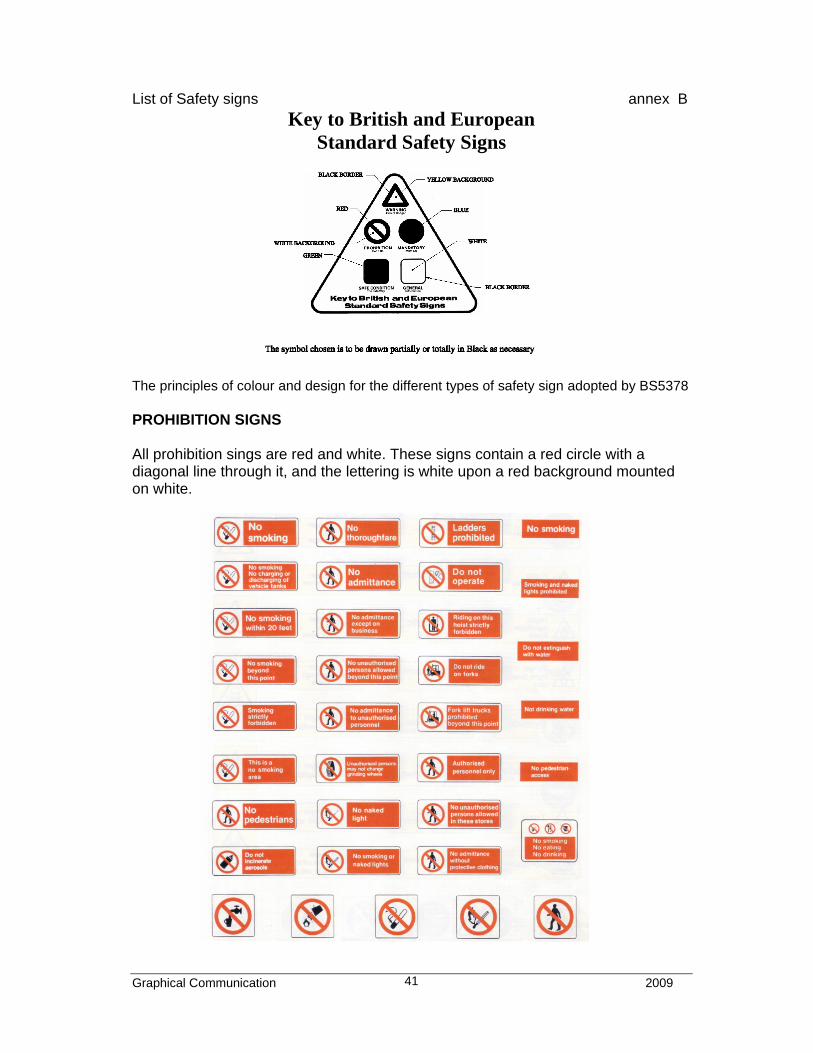
List of Safety signs annex B
Key to British and European Standard Safety Signs
The principles of colour and design for the different types of safety sign adopted by BS5378 PROHIBITION SIGNS All prohibition sings are red and white. These signs contain a red circle with a diagonal line through it, and the lettering is white upon a red background mounted on white.
Graphical Communication 2009 42
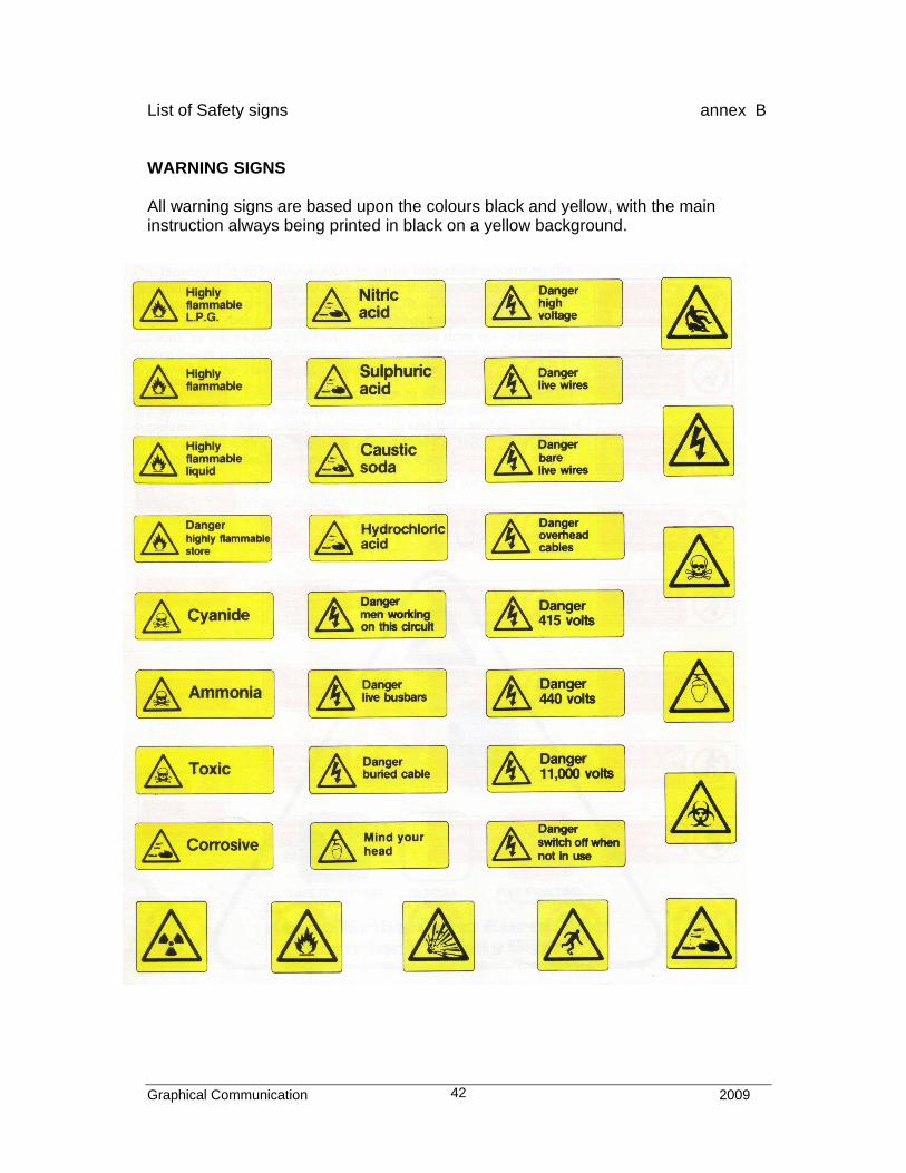
List of Safety signs annex B WARNING SIGNS All warning signs are based upon the colours black and yellow, with the main instruction always being printed in black on a yellow background.
Graphical Communication 2009 43
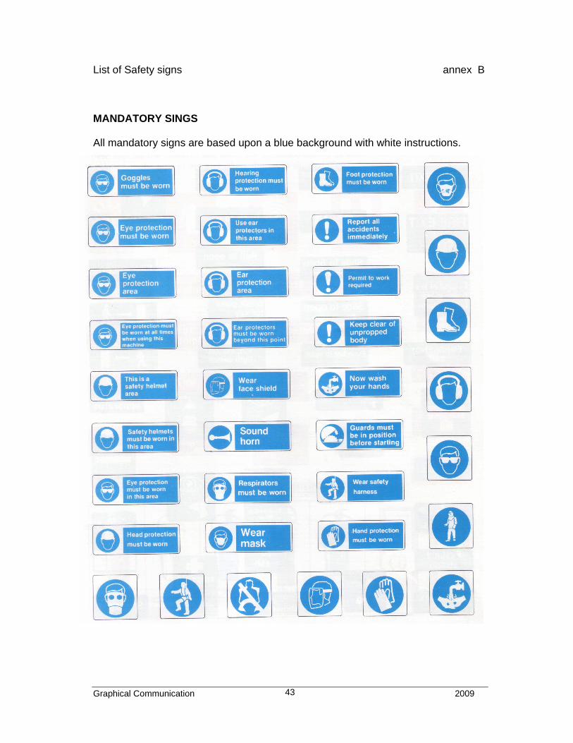
List of Safety signs annex B MANDATORY SINGS All mandatory signs are based upon a blue background with white instructions.
Graphical Communication 2009 44
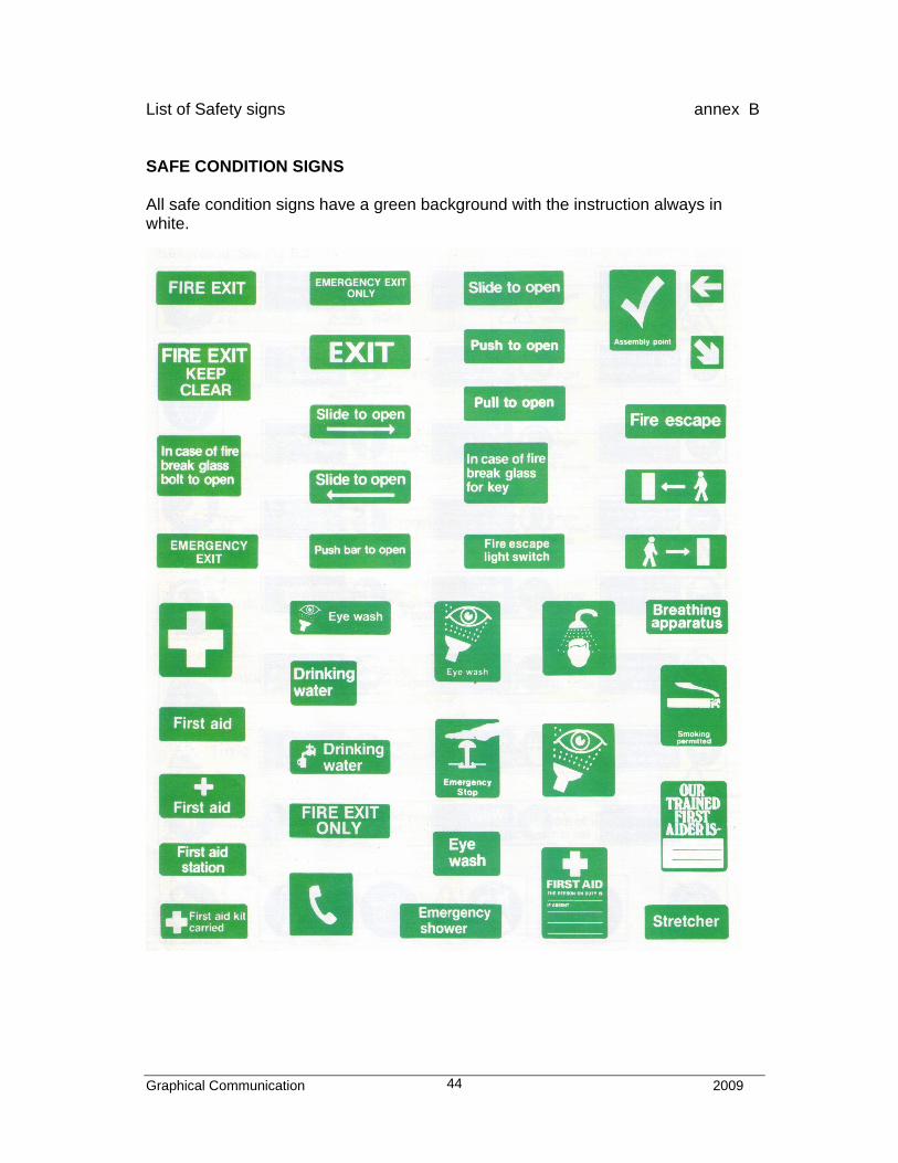
List of Safety signs annex B SAFE CONDITION SIGNS All safe condition signs have a green background with the instruction always in white.
Graphical C
omm
unication
2009
45
Limits of partial or interrupted
Break line
Conventional break lines
CONVENTIONAL REPRESENTATIONS
Conventional break lines
for solid shaftFlat portion on a Shaft
Rectangular section
for hollow shaft (Tube)limit is not an axis
views and sections, if the
Symmetrical either
side of centre line
Wood
Break line
Concrete
Liquid - water
Glass
List of Conventions
annex C

Graphical Communication 2009 46
Graphical C
omm
unication
2009
47
90°
90°
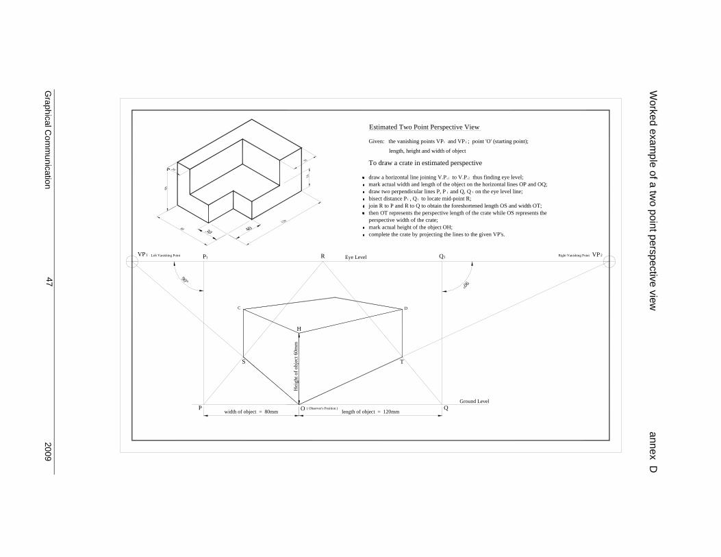
mark actual width and length of the object on the horizontal lines OP and OQ;
To draw a crate in estimated perspective
draw a horizontal line joining V.P. to V.P. thus finding eye level;
Given: the vanishing points VP and VP ; point 'O' (starting point);
length, height and width of object
Estimated Two Point Perspective View
bisect distance P , Q to locate mid-point R;join R to P and R to Q to obtain the foreshortened length OS and width OT;then OT represents the perspective length of the crate while OS represents the
complete the crate by projecting the lines to the given VP's.
draw two perpendicular lines P, P and Q, Q on the eye level line;
perspective width of the crate;mark actual height of the object OH;
Left Vanishing PointVP1 P1 R Eye Level
21
1 1
2
1
1
1
Q1 Right Vanishing Point 2VP
length of object = 120mm
C
H
Hei
ght o
f o
bjec
t 60m
m
S
width of object = 80mmP O ( Observer's Position )
D
T
QGround Level
Worked exam
ple of a two point perspective view
annex D
Graphical C
omm
unication
2009
48
S
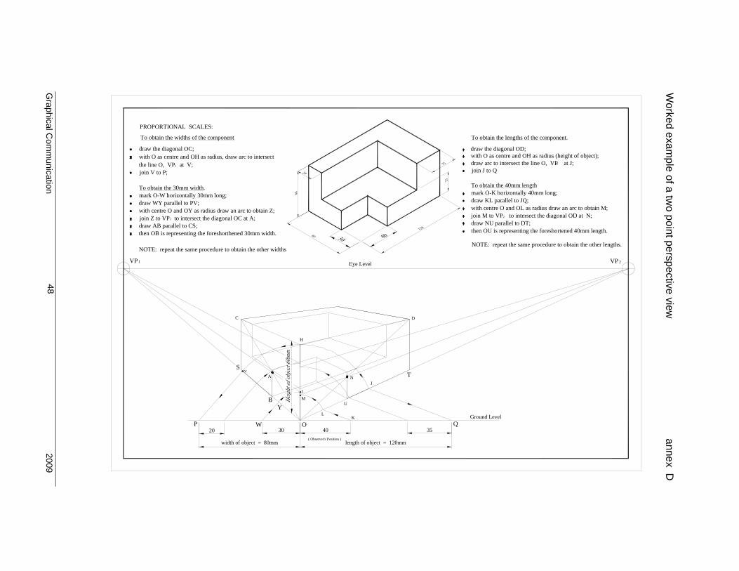
PROPORTIONAL SCALES:
draw the diagonal OC;
the line O, VP at V;join V to P;
with O as centre and OH as radius, draw arc to intersect
To obtain the widths of the component
draw WY parallel to PV;
draw AB parallel to CS;
NOTE: repeat the same procedure to obtain the other widths
with centre O and OY as radius draw an arc to obtain Z;join Z to VP to intersect the diagonal OC at A;
then OB is representing the foreshorthened 30mm width.
mark O-W horizontally 30mm long;To obtain the 30mm width.
1VP
1
1
C
H
Eye Level
D
with O as centre and OH as radius (height of object);
NOTE: repeat the same procedure to obtain the other lengths.
then OU is representing the foreshortened 40mm length.
join M to VP to intersect the diagonal OD at N;with centre O and OL as radius draw an arc to obtain M;
mark O-K horizontally 40mm long;
draw the diagonal OD;
To obtain the 40mm length
To obtain the lengths of the component.
draw arc to intersect the line O, VP at J;join J to Q
2
draw KL parallel to JQ;
draw NU parallel to DT;2
VP2
3540OW
3020P
Z
AV
M
YB
width of object = 80mm
NJ
K
U
L
T
length of object = 120mm( Observer's Position )
QGround Level
Worked exam
ple of a two point perspective view
annex D
Graphical C
omm
unication
2009
49
H
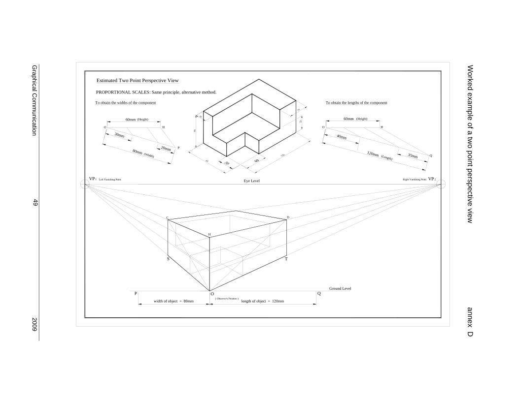
PROPORTIONAL SCALES: Same principle, alternative method.
(Width)
80mm
Estimated Two Point Perspective View
To obtain the widths of the component
O
30mm
60mm (Height)
H
20mm P
Left Vanishing PointVP1
C
Right Vanishing Point
120mm
To obtain the lengths of the component
(Height)60mm
O
40mm
H
Eye Level
D
(Length)35mm Q
2VP
S
width of object = 80mm
P
T
length of object = 120mm( Observer's Position )
O QGround Level
Worked exam
ple of a two point perspective view
annex D

Graphical Communication 2009 50
Graphical Communication 2009 51
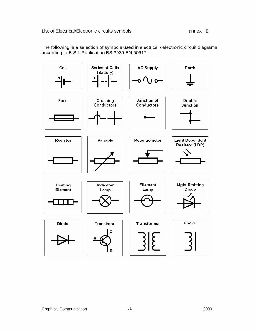
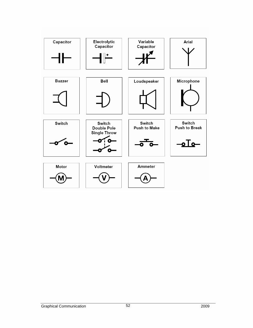
List of Electrical/Electronic circuits symbols annex E The following is a selection of symbols used in electrical / electronic circuit diagrams according to B.S.I. Publication BS 3939 EN 60617.
Graphical Communication 2009 52
Graphical Communication 2009 53
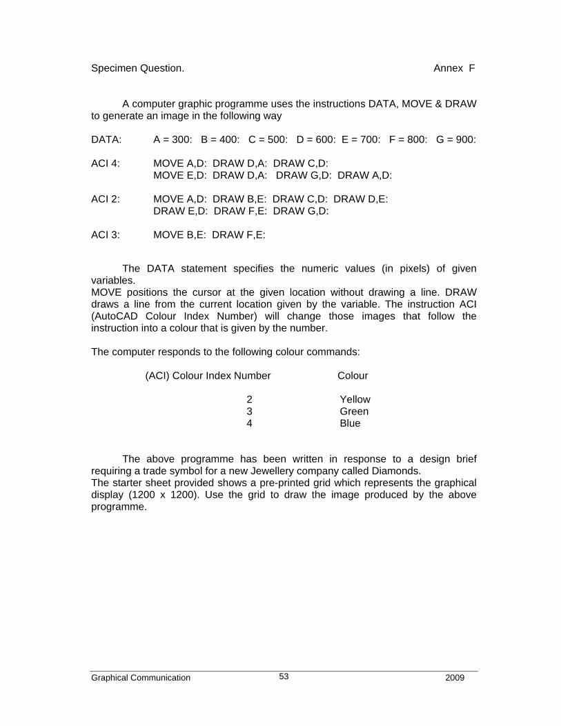
Specimen Question. Annex F
A computer graphic programme uses the instructions DATA, MOVE & DRAW to generate an image in the following way DATA: A = 300: B = 400: C = 500: D = 600: E = 700: F = 800: G = 900: ACI 4: MOVE A,D: DRAW D,A: DRAW C,D: MOVE E,D: DRAW D,A: DRAW G,D: DRAW A,D: ACI 2: MOVE A,D: DRAW B,E: DRAW C,D: DRAW D,E: DRAW E,D: DRAW F,E: DRAW G,D: ACI 3: MOVE B,E: DRAW F,E: The DATA statement specifies the numeric values (in pixels) of given variables. MOVE positions the cursor at the given location without drawing a line. DRAW draws a line from the current location given by the variable. The instruction ACI (AutoCAD Colour Index Number) will change those images that follow the instruction into a colour that is given by the number. The computer responds to the following colour commands: (ACI) Colour Index Number Colour
2 Yellow 3 Green 4 Blue
The above programme has been written in response to a design brief requiring a trade symbol for a new Jewellery company called Diamonds. The starter sheet provided shows a pre-printed grid which represents the graphical display (1200 x 1200). Use the grid to draw the image produced by the above programme.
Graphical Communication 2009 54
600
20000
100
200
100
400
300
500
400300 500
700
800
900
1000
1100
1200
600 700 800 900 1000 1100 1200
Specimen Grid Paper Annex-F
Graphical Communication 2009 55
70000
100 200 300 400 600500
100
200
300
400
500
600
Blue
GREEN
Yellow
800 900 1000 1100 1200
700
800
900
1000
1100
1200
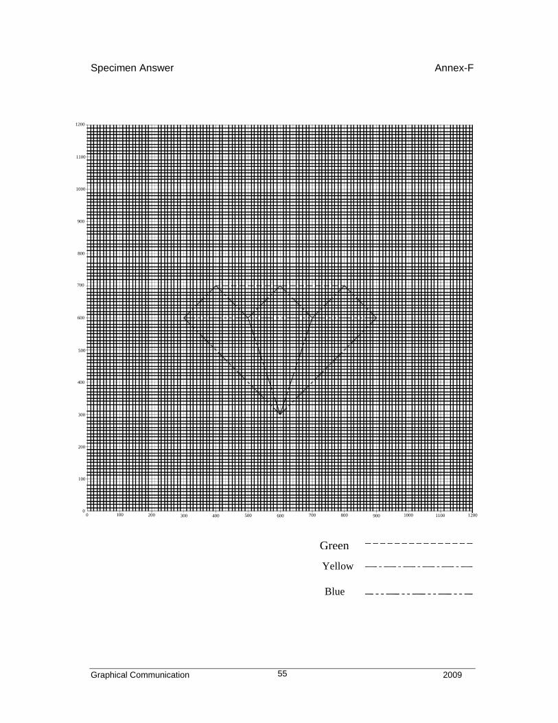
Specimen Answer Annex-F
Green
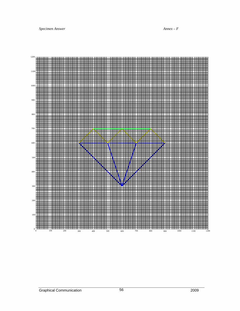
Graphical Communication 2009 56
500
100
100
00
200
200 300
300
400
600
700
800
900
1000
1100
1200
400 500 600 700 1000900800 1100 1200
Specimen Answer Annex – F