Graphic Theatre MultiSync GT2000 /GT2000R · MultiSync GT2000/GT2000R LCD Projector and keep the...
87
MultiSync ™ GT2000 ™ /GT2000R ™ LCD Projector User’s Manual AC IN MENU SELECT ENTER STATUS ZOOM FOCUS POWER ON / OFF - + AC IN MENU SELECT ENTER STATUS ZOOM FOCUS POWER ON / OFF - + Graphic Theatre
Transcript of Graphic Theatre MultiSync GT2000 /GT2000R · MultiSync GT2000/GT2000R LCD Projector and keep the...

MultiSync™ GT2000™/GT2000R™
LCD Projector User’s Manual
AC IN
MENU
SELECT
ENTER
STATUSZOOM
FOCUS
POWER
ON / OFF
-
+
AC IN
MENU
SELECT
ENTER
STATUSZOOM
FOCUS
POWER
ON / OFF
-
+
Graphic Theatre
E-2
PrecautionsPlease read this manual carefully before using your NECMultiSync GT2000/GT2000R LCD Projector and keep themanual handy for future reference.
Your serial number is located under the name plate label on the rightside of your MultiSync GT2000/GT2000R . Record it here:
IMPORTANT INFORMATION
CAUTIONTo turn off main power, be sure to remove the plugfrom power outlet. The power outlet socket should beinstalled as near to the equipment as possible, and shouldbe easily accessible.
CAUTIONTO PREVENT SHOCK, DO NOT OPEN THECABINET. NO USER-SERVICEABLE PARTSINSIDE. REFER SERVICING TO QUALIFIEDNEC SERVICE PERSONNEL.
WARNINGTO PREVENT FIRE OR SHOCK, DO NOT EXPOSE THISUNIT TO RAIN OR MOISTURE. DO NOT USE THISUNIT’S GROUNDED PLUG WITH AN EXTENSIONCORD OR IN AN OUTLET UNLESS ALL THREEPRONGS CAN BE FULLY INSERTED. DO NOT OPENTHE CABINET. THERE ARE HIGH-VOLTAGE COMPO-NENTS INSIDE. ALL SERVICING MUST BE DONE BYQUALIFIED NEC SERVICE PERSONNEL.
Important SafeguardsThese safety instructions are to ensure the long life of your LCDprojector and to prevent fire and shock. Please read them carefully andheed all warnings.
Installation1. For best results, use your LCD projector in a darkened room.
2. Place the projector on a flat level surface in a dry area away from dustand moisture.
3. Do not place your LCD projector in direct sunlight, near heaters orheat radiating appliances.
4. Exposure to direct sunlight, smoke or steam can harm internalcomponents.
5. Handle your LCD projector carefully. Dropping or jarring can dam-age internal components.
6. Do not place heavy objects on top of the LCD projector.
7. If installing the LCD projector on the ceiling:
a. The ceiling must be strong enough to support the LCD projectorand the installation must be in accordance with any local build-ing codes.
b. The LCD projector must be installed by qualified NEC servicepersonnel.
Power Supply1. The LCD projector is designed to operate on a power supply of 100-
120 or 220-240 V 50/60 Hz AC. Ensure that your power supply fitsthis requirement before attempting to use your LCD projector.
2. Handle the power cable carefully and avoid excessive bending. Adamaged cord can cause electric shock or fire.
3. If the LCD projector is not to be used for an extended period of time,disconnect the plug from the power outlet.
Three types of power cable are supplied with this LCD projector: three-pin type for Japan, U. S. A. and Canada. Two-pin type for Germany.
3. GSGV Acoustic Noise Information Ordinance:The sound pressure level is less than 70 dB(A) according to ISO 3744 orISO 7779.
This symbol warns the user that uninsulatedvoltage within the unit may be sufficient tocause electrical shock. Therefore, it is dan-gerous to make any kind of contact with anypart inside of the unit.
This symbol alerts the user that importantinformation concerning the operation andmaintenance of this unit has been provided.The information should be read carefully toavoid problems.
For Japan(black)
For Germany For NorthAmerica(gray)
DOC Compliance NoticeThis Class A digital apparatus meets all requirements of the
Canadian Interference-Causing Equipment Regulations.
RF InterferenceWARNING
The Federal Communications Commission does not allow anymodifications or changes to the unit EXCEPT those specified byNEC Technologies in this manual. Failure to comply with thisgovernment regulation could void your right to operate this equip-ment.This equipment has been tested and found to comply with the limitsfor a Class A digital device, pursuant to Part 15 of the FCC Rules.These limits are designed to provide reasonable protection againstharmful interference in a commercial installation. This equipmentgenerates, uses and can radiate radio frequency energy and, if notinstalled and used in accordance with the instructions, may causeharmful interference to radio communications. Operation of thisequipment in a residential area is likely to cause harmful interfer-ence in which case the user will be required to correct the interfer-ence at their own expense.
E-3
Cleaning1. Unplug the LCD projector before cleaning.2. Clean the cabinet periodically with a damp cloth. If heavily soiled,
use a mild detergent. Never use strong detergents or solvents such asalcohol or thinner.
3. Use a blower or lens paper to clean the lens, and be careful not toscratch or mar the lens.
4. Clean the air filter with a vacuum cleaner after every 100 hours ofoperation.
a. Clean the outside of the filter with a vacuum cleaner.b. Do not use water or any other liquid to clean the air filter.c. Do not operate your LCD projector without the air filter.
Lamp Replacement• Perform lamp replacement in accordance with the instructions on
page E-73.
• Be sure to replace the lamp when the Status light comes on. If youcontinue to use the lamp after 2000 hours of use, the lamp bulb mayshatter, and pieces of glass may be scattered in the lamp case. Do nottouch them as the pieces of glass may cause injury. If this happens,contact your NEC dealer for lamp replacement.
• Allow a minimum of ONE minute to elapse between turning the lampoff and on. High voltage is applied to the lamp immediately when thepower is turned on. Therefore turning the power off and quickly backon may shorten the life of your lamp and result in damage to yourLCD projector.
Fire and Shock Precautions1. Ensure that there is sufficient ventilation and that vents are unob-
structed to prevent the build-up of heat inside your LCD projector.Allow at least 3 inches (10cm) of space between your LCD projectorand a wall.
2. Prevent foreign objects such as paper clips and bits of paper fromfalling into your LCD projector. Do not attempt to retrieve any objectsthat might fall into your projector. Do not insert any metal objectssuch as a wire or screwdriver into your LCD project. If somethingshould fall into your projector, disconnect it immediately and have theobject removed by a qualified NEC service person.
3. Do not place any liquids or plants (which require liquids) on top ofyour LCD projector.
• Do not look into the lens while the projector is on.Serious damage to your eyes could result.
E-4
Ce symbole a pour but de prévenirl’utilisateur de la présence d’une tensiondangereuse, non isolée se trouvant àl’intérieur de l’appareil. Elle est d’uneintensité suffisante pour constituer un risqued’électrocution. Eviter le contact avec lespièces à l’intérieur de cet appareil.Ce symbole a pour but de prévenirl’utilisateur de la présence d’importantes in-structions concernant l’entretien et lefonctionnement de cet appareil. Parconséquent, elles doivent être luesattentivement afin d’éviter des problèmes.
ATTENTIONRISQUE D’ELECTROCUTION NE PAS OUVRIR
AVERTISSEMENTAFIN DE REDUIRE LES RISQUES D’INCENDIE OUD’ELECTROCUTION, NE PAS EXPOSER CETAPPAREIL A LA PLUIE OU A L’HUMIDITE. AUSSI, NEPAS UTILISER LA FICHE POLARISEE AVEC UNPROLONGATEUR OU UNE AUTRE PRISE DE COU-RANT SAUF SI CES LAMES PEUVENT ETRE INSEREESA FOND. NE PAS OUVRIR LE COFFRET, DESCOMPOSANTES HAUTE TENSION SE TROUVENT AL’INTERIEUR. LAISSER A UN PERSONNEL QUALIFIELE SOIN DE REPARER CET APPAREIL.
ATTENTIONPour couper l'alimentation principale, s'assurer deretirer la fiche de la prise de courant.La prise de courant murale doit être installée leplus près possible de l'équipement, et doit êtrefacilement accessible.
DOC avis de conformationDOC avis de conformation
Cet appareil numérique de la classe A respecte toutes les exigencesdu Règlement sur le Matériel Brouilleur du Canada.
Importantes précautions de sécuritéLes points suivants sont des précautions de sécurité importantesdestinées à garantir une longue durée de service du projecteur àécran à cristaux liquides (LCD) et afin d’éviter un incendie et desrisques d’électrocution. S’assurer de lire attentivement cesprécautions de sécurité et respecter tous les avertissements décritsci-dessous.
Installation1. Pour un fonctionnement optimal, utiliser le projecteur à écran à
cristaux liquides (LCD) dans une pièce sombre.
2. Placer le projecteur à écran à cristaux liquides (LCD) sur unesurface à niveau et dans un endroit sec exempt de poussières etd’humidité.
3. Ne pas placer le projecteur à écran à cristaux liquides (LCD) enplein soleil, près d’appareils ménagers ou d’autres appareils dechauffage.
4. La fumée, la vapeur et l’exposition aux rayons directs du soleilrisquent de détériorer sérieusement les composantes internes.
5. Eviter des manipulations brusques lors du déplacement duprojecteur à écran à cristaux liquides (LCD), car un choc violentpourrait endommager les composantes internes.
6. Ne pas deposer d’objets lourds sur le dessus du projecteur à écranà cristaux liquides (LCD).
7. Lors de l’installation du projecteur à écran à cristaux liquides(LCD) au plafond, respecter les instructions suivantes.
a. Le plafond doit être suffisamment solide pour supporter lepoids du projecteur à écran à cristaux liquides (LCD) et ildoit être installé selon les codes de construction locaux.
b. Le projecteur à écran à cristaux liquides (LCD) doit êtreinstallé par un personnel qualifié.
Alimentation1. Le projecteur à écran à cristaux liquides (LCD) est conçu pour
fonctionner à 100-120 ou 220-240VCA 50/60Hz. S’assurer que latension d’alimentation locale satisfait cette exigence avantd’utiliser le projecteur.
2. Manipuler le câble d’alimentation avec précaution et éviter de leplier excessivement. Un cordon endommagé risque de provoquerune électrocution ou un incendie.
3. Si le projecteur à écran à cristaux liquides (LCD) n’est pas utilisépendant une période prolongée, retirer la fiche de la prise secteur.

E-5
Nettoyage1. Débrancher le projecteur à écran à cristaux liquides (LCD) de la
prise d’alimentation avant le nettoyage.
2. Nettoyer régulièrement le coffret avec un chiffon doux. S’il y ades taches tenaces, utiliser une solution d’un détergent doux. Nejamais utiliser de détergents puissants ou des solvants, tel quel’alcool ou un diluant pour nettoyer le projecteur à écran à cristauxliquides (LCD).
3. Utiliser un appareil diffuseur chauffant ou du papier de nettoyagede lentille disponible dans le commerce pour nettoyer la lentille.
Ne pas frapper ou rayer la surface de la lentille, car des défautsrisquent de se produire sur la surface de la lentille.
4. Nettoyer le filtre à air toutes les 100 heures.
a. Nettoyer seulement l’extérieur avec un aspirateur.
b. Ne pas nettoyer le filtre à air avec de l’eau ou un liquide.
c. Ne pas utiliser le projecteur à écran à cristaux liquides (LCD)sans le filtre à air.
Remplacement de la lampe• Effectuer le remplacement de la lampe suivant les instructions de
la page 75.
• Assurez-vous de bien remplacer la lampe lorsque le voyantd’usure s’allume. Si vous continuez d’utiliser la lampe après 2000heures d’utilisation, l’ampoule peut se briser et des brisures deverre peuvent être éparpillées dans le compartiment de la lampe.Ne les touchez pas car elles peuvent vous blesser. Dans ce cas,contactez votre revendeur NEC afin de procéder au remplacementde la lampe.
• Attendez minimum UNE minute après avoir éteint la lampe avant dela rallumer. Une haute tension est immédiatement appliquée à lalampe quand celle-ci est mise sous tension. Par conséquent, éteindre,puis tout de suite rallumer peut abréger la vie de votre lampe etendommager votre projecteur LCD.
Précautions pour éviter un incendieou une électrocution1. Une ventilation appropriée doit être assurée afin d’éviter une accu-
mulation de chaleur à l’intérieur du projecteur à écran à cristauxliquides (LCD). S’assurer que les trous de ventilation ne sont pasobstrués. Laisser un espace d’au moins 10 cm (quatre pouces) entrele projecteur à écran à cristaux liquides (LCD) et les murs.
2. Eviter que des objets étrangers, des agrafes, des clous et du papier, parexemple, pénètrent à l’intérieur du projecteur à écran à cristauxliquides (LCD). Ne pas essayer de récupérer ces objets soi-même oune pas insérer des objets métalliques, des fils et des tourne-vis, parexemple à l’intérieur du projecteur à écran à cristaux liquides (LCD).Si un objet tombe à l’intérieur du projecteur à écran à cristaux liquides(LCD), le débrancher immédiatement et contacter un dépanneurqualifié pour retirer l’objet.
3. Ne pas placer des liquides sur le dessus du projecteur à écran àcristaux liquides (LCD).
• Ne regardez pas à l’intérieur de l’objectif lorsque leprojecteur est en marche. Vous risquez de vous blessergravement aux yeux.

E-6
NEC MultiSync®
LCD Projector ProductsNEC Technologies, Inc. (hereafter NECTECH) warrants thisproduct to be free from defects in material and workmanshipunder the following terms.
This warranty extends only to you, the original purchaser, andis not transferable. This warranty extends only to products anddistributed by us in the U.S.A or Canada.
HOW LONG IS THE WARRANTY?Parts and labor are warranted for (2) two years from the dateof the first customer purchase. The lamp is warranted for 2000hours of operating time or six months, whichever comes first.
WHO IS PROTECTED?This warranty may be enforced only by the first purchaser.
WHAT IS COVERED AND WHAT IS NOTCOVEREDExcept as specified below, this warranty covers all defects inmaterial or workmanship in this product. The following arenot covered by the warranty:
1.Any product which is not distributed in the U.S.A. orCanada by NECTECH or which is not purchased in theU.S.A. or Canada from an authorized NECTECH dealer.For a listing of authorized dealers please contactNECTECH at 800-836-0655.
2.Any product on which the serial number has been defaced,modified or removed. NECTECH’S LIABILITY FORANY DEFECTIVE PRODUCT IS LIMITED TO THEREPAIR OR REPLACEMENT OF THE PRODUCT ATOUR OPTION. REPLACEMENT PRODUCTS MAY BENEW OR ‘LIKE NEW’.
3.NECTECH SHALL NOT BE LIABLE FOR : Damage,deterioration or malfunction resulting from:
a. Accident, misuse, abuse, neglect, fire, water, lightningor other acts of nature, unauthorized product modifica-tion, or failure to follow instructions supplied with theproduct.
b. Repair or attempted repair by anyone not authorized byNECTECH.
c. Any shipment of the product (claims must be presentedto the carrier).
d. Removal or installation of the product.
e. Any other cause which does not relate to a productdefect.
4.Cartons, carrying cases, batteries, external cabinets, mag-netic tapes, or any accessories used in connection with theproduct.
WHAT NEC WILL COVERWe will pay labor and material expenses for covered items.But we will not pay for the following:
LIMITED WARRANTY (USA AND CANADA ONLY)
1.Removal or installation charges.
2.Costs of initial technical adjustments (set-up), includingadjustment of user controls. These costs are the responsibil-ity of the NECTECH dealer from whom the product waspurchased.
3.Payment of shipping charges.
HOW YOU CAN GET WARRANTY SERVICE1.To obtain service on your product, consult the dealer from
whom you purchased the product.
2.Whenever warranty service is required, the original datedinvoice (or a copy) must be presented as proof of warrantycoverage. Please be prepared to describe or demonstrate theproblem to your dealer.
3.For the name of the nearest NECTECH authorized servicecenter, call NECTECH at 800-836-0655.
LIMITATION OF IMPLIED WARRANTIESALL IMPLIED WARRANTIES, INCLUDING WARRAN-TIES OF MERCHANTABILITY AND FITNESS FOR APARTICULAR PURPOSE, ARE LIMITED IN DURATIONTO THE LENGTH OF THIS WARRANTY.
EXCLUSION OF DAMAGESNECTECH’S LIABILITY FOR ANY DEFECTIVE PROD-UCT IS LIMITED TO THE REPAIR OR REPLACEMENTOF THE PRODUCT AT OUR OPTION. NECTECH SHALLNOT BE LIABLE FOR:
1.DAMAGE TO OTHER PROPERTY CAUSED BY ANYDEFECTS IN THIS PRODUCT, DAMAGES BASEDUPON INCONVENIENCE, LOSS OF USE OF THEPRODUCT, LOSS OF TIME, COMMERCIAL LOSS; OR
2.ANY OTHER DAMAGES, WHETHER INCIDENTAL,CONSEQUENTIAL OR OTHERWISE. SOME STATESDO NOT ALLOW LIMITATIONS ON HOW LONG ANIMPLIED WARRANTY LASTS AND/OR DO NOT AL-LOW THE EXCLUSION OR LIMITATION OF INCI-DENTAL OR CONSEQUENTIAL DAMAGES, SO THEABOVE LIMITATIONS AND EXCLUSIONS MAY NOTAPPLY TO YOU.
HOW STATE LAW RELATES TO THE WARRANTYThis warranty gives you specific legal rights, and you mayalso have other rights which vary from state to state.
FOR MORE INFORMATION, TELEPHONE 800-836-0655
NEC TECHNOLOGIES, INC.1250 N. Arlington Heights Road, Suite 500Itasca, Illinois 60143-1248
NOTE: All products returned to NECTECH for serviceMUST have prior approval. To get approval, call NECTechnologies at800-836-0655.

E-7
1. IntroductionWhat’s In The Box? ...................................................................................................... E-8Getting To Know Your MultiSync GT2000/GT2000R LCD Projector .......................... E-9
Projector Cabinet ................................................................................................... E-9Top Features ........................................................................................................ E-10Terminal Panel Features ....................................................................................... E-11Remote Control Features ..................................................................................... E-13
2. InstallationSetting Up Your MultiSync GT2000/GT2000R LCD Projector .................................. E-17
Using A Tabletop Or Cart .................................................................................... E-18Adjusting The Focus On GT2000R...................................................................... E-18Ceiling Installation ............................................................................................... E-21Reflecting The Image/ Rear Screen Projection (GT2000R Only) ......................... E-23
3. ConnectionsWiring Diagram .......................................................................................................... E-25PC Control .................................................................................................................. E-26Connections With ISS-6020 ........................................................................................ E-28
Connecting One ISS-6020 ................................................................................... E-28Connecting Multiple ISS-6020s ........................................................................... E-29
Connecting Multiple Projectors .................................................................................. E-30Operating Multiple Projectors With Remote Control .................................................. E-31External Control .......................................................................................................... E-32
4. OperationGeneral Controls ......................................................................................................... E-34Set-Up .........................................................................................................................E-36Adjusting The Picture And The Audio ........................................................................ E-44Adjusting The Screen .................................................................................................. E-49Using User Memory And Channel Memory ................................................................ E-56Controlling Switcher ................................................................................................... E-70
4. MaintenanceReplacing The Lamp ................................................................................................... E-73
Cleaning And Replacing The Filter ............................................................................. E-74Remote Control Battery Installation ............................................................................ E-74
5. TroubleshootingStatus Light Messages ................................................................................................. E-77Common Problems & Solutions .................................................................................. E-78
6. SpecificationsOptical ........................................................................................................................E-79
Electrical .....................................................................................................................E-79Mechanical ................................................................................................................. E-79D-Sub Pin Assignments .............................................................................................. E-81Displayable Video Signals ........................................................................................... E-82PC Control Command Reference ................................................................................ E-83
TABLE OF CONTENTS

E-8
What’s In The Box?Make sure your box contains everything listed. If any pieces aremissing, contact your dealer. Please save the original box andpacking materials if you ever need to ship your MultiSync GT2000/GT2000R LCD Projector.
• NEC MultiSync GT2000/GT2000R LCD Projector• Remote Control And Cables• Power Cable• Two AAA Batteries• User’s Manual• String and Rivet (GT2000 only)• Ferrite Clamp
Power cable (3 types)
INTRODUCTION
Remote control
Batteries (AAA22)
Remote cable String and rivet (GT2000 only)
For Germany For Japan For USA or Canada
User’ s manual (English / German andJapanese)
User'sManual
Ferrite clamp for remote cable
Lens cap (attatched to the projector at the factory)
For GT2000 For GT2000R
1

E-9
MENU
SELECT
ZOOMFOCUS
STATUS
POWER
ON / OFF
ENTER
AC IN
MENU
SELECT
ENTER
STATUSZOOM
FOCUS
POWER
ON / OFF
-
+
-
+-
+
Getting To Know Your MultiSyncGT2000/GT2000R LCD Projector
Built-In Speaker(2W)
Remote Sensor
Built-In Speaker(2W)
AC InputPlug the female end of the suppliedpower cable here, and the male endinto a properly grounded outlet.
Main Power Switch
Lens Cap
Remote Sensor
Remote Sensor
One-TouchTilt button
Remote Sensor
Lens
Front Vent
Filter Cover
Lamp Housing Cover
Latch
Tilt Foot
Tilt Foot
Terminal Panel
Rear Foot
Top Features

E-10
MENU
SELECT
ENTER
STATUS
ZOOM FOCUS
POWER
ON / OFF
- +
-
+
-
+
Top Features1 Power Button
Use this button to turn the power on and off when the MainPower Switch is on and the LCD projector is in standby.
To turn off the projector, press and hold this button for atleast 2 seconds.
2 Menu Button
Displays the on- screen menu. A press of this button whilethe on-screen menu is displayed will move back to theprevious menu step.
3 Select ( § ©) / (+)(–) Buttons
Select: After you press the “Menu” button, use the or button to select the menu item you wish toadjust.
(+)(–): Use these buttons while you' re in the adjustmentmode to change the level of a selected menu item.These buttons are also used to set an item in theother menus.
4 Enter Button
Executes your menu selection.
5 (+) (–) Zoom Buttons
Press the (+) button to make the image larger; press (–) tomake the image smaller. (This feature is not available onGT2000R.)
6 (+) (–) Focus Buttons
Press the (+) or (–) buttons to focus an image. (This feature isnot available on GT2000R.)
7 Power Indicator
When this indicator is green, the LCD projector is on; whenthe indicator is amber, it is in standby mode.
8 Status Indicator
When this is lit red continually, it's warning you that theprojection lamp has exceed 2000 hours of service. After thislight appears, it is advisable to replace the projection lamp assoon as possible.(See page E-73)In addition the message "LAMP USAGE XX HOURS"appears continually when the on-screen menu is not dis-played.If this light blinks red rapidly, it indicates that either the lampcover or filter cover is not attached properly. See the StatusLight Messages on page E-77 for more details.When the GT2000/GT2000R is used with the ISS-6020switcher in bundled operation, this indicator lights green.The green light blinks when the ISS-6020 Switcher is notconnected with the projector correctly.
2
3
4
6
51
8
7
(§ ©)
MENU
SELECT
ZOOMFOCUS
STATUS
POWER
ON / OFF
ENTER

E-11
Terminal Panel FeaturesThis panel is located on the left side and is where you connect yourcables.
1
8
2
4
3
5 6 7
1 R/Cr, G/Y, B/Cb, H/ HV and V [RGB 1] Inputs (BNC)Connect R,G,B,H (Horizontal sync) and V (Vertical sync)outputs of external equipment such as the NEC ISS-6020Switcher or IPS-4000.
If using a component with a combined sync (SYNC) output,connect it to the H/V terminal. When using luminance andcolor-difference signals of HDTV and DVD, connect Pr/Crto the R, Y to the G and Pb/Cb to the B input of the projector.
2 RGB (Y, Cb,Cr) Input 2 Connector (Mini D-Sub 15 pin)Connect your PC, DVD player with Y/Cb/Cr outputs orother RGB equipment such as IBM or compatible comput-ers. The optional Component V. Cable is required for Y/Cb/Cr input connection.
3 RGB Output Connector (Mini D-Sub 15 pin)You can use this connector to loop your computer image toan external monitor from either the RGB 1 or RGB 2 inputsource.
4 S-Video InputHere is where you connect the S-Video input from an exter-nal source such as a VCR or laser disc player.
NOTE: S-Video provides more vivid color and higherresolution than the traditional composite video format.
5 Left Channel/Mono Audio Input Jack (RCA)This is your left channel audio input for stereo sound comingfrom S-Video equipment or audio system. This also serves asyour monaural audio input.
Right Channel Audio Input JackThis is your right channel audio input for stereo sound.
6 RGB 2 Audio Input Mini JackYou can use this connector to output sound from the RGB 2Input source.
7 RGB 1 Left Channel/Mono Audio Input Jack (RCA)This is your left channel audio input for stereo sound comingfrom the RGB Input 1 source.
This also serves as your monaural audio input.
RGB 1 Right Channel Audio Input JackThis is your right channel audio input for stereo sound fromthe RGB Input 1 source.
8 Remote 2/PC Connector (Mini D-Sub 15 pin)Use this connector to attach an RS-232C cable when acomputer or similar device will control the projector or whenthe projector is used with multiple projectors.
R/Cr G/Y B/Cb H/HV V
RGB INPUT 2
RGBOUTPUT
S-VIDEO INPUT AUDIO
VIDEO INPUT AUDIO
REMOTE 1
RGB 1 AUDIOREMOTE 2/PC
EXT-CTL
RGB 2AUDIO
AUDIOOUTPUT
REMOTEOUTPUT
REMOTEINPUTL/MONO R L/MONO R
L/MONO R

E-12
AC IN
15
9
11 1310 12 14
9 Remote Input Mini JackConnect your remote control cable here for wired operation.
Remote Output Mini Jack
This terminal enables you to loop up to 64 projectors withthe same remote control operation.
10 Video Input (RCA)Connect a VCR, DVD player, laser disc player, or documentcamera here to project video.
11 Left Channel/Mono Audio Input Jack (RCA)This is your left channel audio input for stereo sound comingfrom video equipment or audio system. This also serves asyour monaural audio input.
Right Channel Audio Input Jack
This is your right channel audio input for stereo sound.
12 Audio Output Mini JackConnect additional external speakers here to listen to audiocoming from the RGB 1, RGB 2, Video or S-Video input.
13 REMOTE 1 Connector (Mini D-Sub 15 pin)Connect the control cable (available as an option) here whenthe projector is used with the optional ISS-6020 or withmultiple projectors.
NOTE: The ISS-6020/ISS-6020G Switcher is compat-ible with this projector.
14 External Control Connector (Mini D-Sub 15 pin)This connector is for switch closure control or other externalcontroller.
15 Built-in Security Slot ( )This security slot supports the MicroSaver® Security Sys-tem.
MicroSaver® is a registered trademark of KensingtonMicroware Inc. The logo is trademarked and owned byKensington Microware Inc.
S-VIDEO INPUT AUDIO
VIDEO INPUT AUDIO
REMOTE 1
RGB 1 AUDIOREMOTE 2/PC
EXT-CTL
RGB 2AUDIO
AUDIOOUTPUT
REMOTEOUTPUT
REMOTEINPUTL/MONO R L/MONO R
L/MONO R
E-13
OFF
+-
+
-
RGB1
ABC DEF GHI
JKL MNO PQR
STU
,. LOAD CLEAR
CONTRAST
SETUP NORMAL
AUDIOMUTE
EXPAND
FOCUS ZOOM
W
T
DISPLAY
Adr.
VOLUMEBRIGHT
PICTURE
VWX YZ?
RGB2 VIDEO/S-VIDEO
ONPOWER
MENU
ENTER
1 2 3
4 5 6
7
0
8 9
KEYSTONE
CTL
MAGNIFY/REDUCE
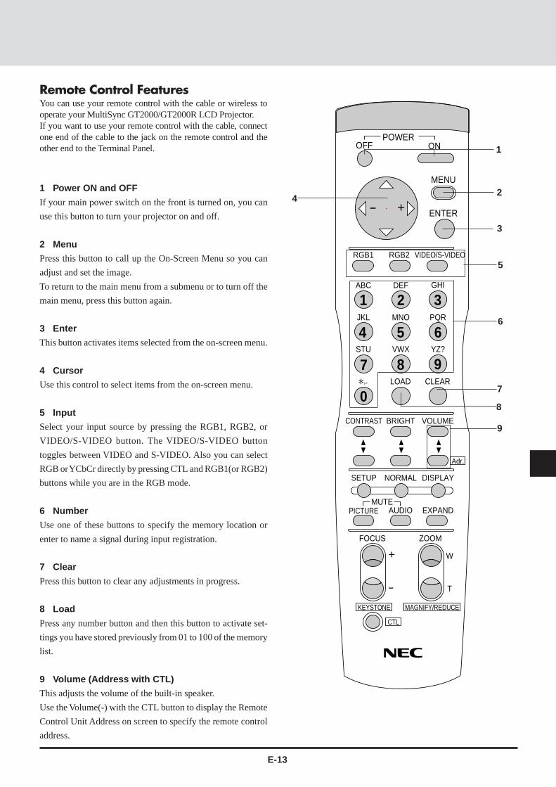
Remote Control FeaturesYou can use your remote control with the cable or wireless tooperate your MultiSync GT2000/GT2000R LCD Projector.If you want to use your remote control with the cable, connectone end of the cable to the jack on the remote control and theother end to the Terminal Panel. 1
5
24
6
8
7
9
1 Power ON and OFF
If your main power switch on the front is turned on, you can
use this button to turn your projector on and off.
2 Menu
Press this button to call up the On-Screen Menu so you can
adjust and set the image.
To return to the main menu from a submenu or to turn off the
main menu, press this button again.
3 Enter
This button activates items selected from the on-screen menu.
4 Cursor
Use this control to select items from the on-screen menu.
5 Input
Select your input source by pressing the RGB1, RGB2, or
VIDEO/S-VIDEO button. The VIDEO/S-VIDEO button
toggles between VIDEO and S-VIDEO. Also you can select
RGB or YCbCr directly by pressing CTL and RGB1(or RGB2)
buttons while you are in the RGB mode.
6 Number
Use one of these buttons to specify the memory location or
enter to name a signal during input registration.
7 Clear
Press this button to clear any adjustments in progress.
8 Load
Press any number button and then this button to activate set-
tings you have stored previously from 01 to 100 of the memory
list.
9 Volume (Address with CTL)
This adjusts the volume of the built-in speaker.
Use the Volume(-) with the CTL button to display the Remote
Control Unit Address on screen to specify the remote control
address.
3

E-14
OFF
+-
+
-
RGB1
ABC DEF GHI
JKL MNO PQR
STU
,. LOAD CLEAR
CONTRAST
SETUP NORMAL
AUDIOMUTE
EXPAND
FOCUS ZOOM
W
T
DISPLAY
Adr.
VOLUMEBRIGHT
PICTURE
VWX YZ?
RGB2 VIDEO/S-VIDEO
ONPOWER
MENU
ENTER
1 2 3
4 5 6
7
0
8 9
KEYSTONE
CTL
MAGNIFY/REDUCE
10
10 Contrast
Adjusts the image' s contrast for room conditions.
11 Brightness
Adjusts the image' s brightness for room conditions.
12 Setup
Press this button and then press the ENTER button to return to
the factory preset. Also you can search the memory by press-
ing the SETUP button and then the LOAD button.
13 Normal
This button returns the brightness, contrast or white balance
to its factory default settings.
14 Display
Press this button to identify the source being projected.
15 Picture Mute
This button turns off the image and the on-screen message for
a short period of time. Press again to restore it.
16 Audio Mute
This button temporarily shuts off or restores the sound.
17 Expand (Digital Zoom Function)
Press this button to turn the image enlargement control on or
off.
18 Focus (Keystone with CTL)
Press the (+) or (-) button to adjust the focus. (These buttons
are not available on GT2000R.)
Use these buttons with the CTL button to correct the keystone
(trapezoidal) distortion, and make the image square.
14
15
16
17
18
11
12
13

E-15
OFF
+-
RGB1
ABC DEF GHI
JKL MNO PQR
RGB2 VIDEO/S-VIDEO
ONPOWER
MENU
ENTER
1 2 3
4 5 6
+
-
SETUP NORMAL
AUDIOMUTE
EXPAND
FOCUS ZOOM
W
T
DISPLAY
Adr.
PICTURE
KEYSTONE
CTL
MAGNIFY/REDUCE
19
20
21
19 Zoom (Magnify/Reduce with CTL)
Press the (W) or (T) button to zoom in or zoom out. (These
buttons are not available on GT2000R.)
Use these buttons with the CTL button to adjust the image
size.
20 CTL(Control)
This button is pressed simultaneously with others (FOCUS,
ZOOM, VOLUME, RGB1, RGB2, KEYSTONE, MAGNIFY,
REDUCE, Adr. and direct selection of RGB and YCbCr) to
operate functions.
21 Remote Jack
Connect your remote control cable here for wired operation.

E-16
Remote Control Notes• Use the remote control within a distance of about 7m (23feet)
and at an angle of 30˚ above, below, to the left and to the right of
the remote control sensor located at the front of the main unit.
• The remote control system may not function when direct
sunlight or strong illumination strikes the remote control sensor
of the main unit, or when there is an obstacle in the path.
• When remote control buttons are pressed and held, main unit
function keys may not operate.
• Do not subject to strong shock.
• Do not allow water or other liquid to splash on the remote
control. If the remote control gets wet, wipe it dry immediately.
• Avoid exposure to heat and steam.
• Remove the batteries from the remote control when the remote
control is not going to be used for a long period.
You cannot operate the projector using the remote con-trol if:
• the remote ID is not set to [00].
• the remote ID is not the same as the projector ID.
See page E-43 for setting remote ID and page E-38 for settingprojector ID.
Attaching the supplied ferrite clamp
The ferrite clamp is provided with this projector in order to reduceelectromagnetic interference that may cause interference to radiocommunication.
1. Push the catch and open the ferrite clamp.
2. Draw the remote cable through the hole and wind the remotecable around the ferrite clamp two times, then close the ferriteclamp. Place the ferrite clamp as closely to the end of the cablethat plugs into the projector as possible.

E-17
INSTALLATION2This section describes how to set up your MultiSync GT2000/GT2000R LCD projector and how to connect video and audiosources.
Setting Up Your MultiSync GT2000/GT2000R LCD ProjectorYour MultiSync GT2000/GT2000R LCD Projector is simple toset up and use. But before you get started, you must first:
1. Determine the image size
2. Set up a screen or select a non-glossy white wall onto whichyou can project your image.
Carrying The LCD Projector Ensure that the power cord andany other cables connecting to video sources are disconnectedbefore moving the projector. When moving the projector orwhen it is not in use, cover the lens with the lens cap.
Selecting A Location The further your LCD projector is fromthe screen or wall, the larger the image. The minimum size theimage can be is approximately 0.5 m (20") measured diago-nally when the projector is roughly 1.0 m from the wall orscreen. The largest the image can be is 7.6 m (300") when theprojector is about 12.0 m from the wall or screen.
Width
Height Screen size(diagonal)
Projection distance
Attaching the lens cap to the lens hood with the suppliedstring and rivet. (GT2000 only)
Lens cap
Rivet
String

E-18
Using A Tabletop Or Cart1. Place your LCD projector on a flat level surface at the
optimal distance from the screen or wall so you realize thesize image you want. (Avoid having bright room lighting orsun light directly on the screen or wall where you'll beprojecting the image.)
2. Connect the power cable, remove the lens cap and turn theprojector on. (If no input signal is available, the projector willdisplay a background image.)
3. Ensure that the projector is centered to the screen.
4. Move the projector left or right to center the image horizon-tally on the screen. (A)
5. To center the image vertically (B), lift the front edge of theprojector and press the buttons on the front of the projector,just above the feet, to release the one-touch tilt feet. (There isapproximately 10.5˚ of up and down adjustment for the frontof the projector. )
6. If a trapezoidal distortion appears on the screen, use theFocus and CTL buttons on the remote control or select theKeystone from the Settings Menu under the Main menu.
Note: The keystone function is not available if no input signalis present.
If necessary, adjust the front or rear feet so that the lenssurface is parallel to the screen. If you use the projector withthe screen tilted, the picture will be distorted. Each of the rearfeet height can be changed up to 5mm (0.2”).
7. Increase or reduce the size of the projected image by press-ing the "Zoom" (+) or (–) buttons on the remote control ortop of the cabinet. (The zoom buttons are not available onGT2000R.)
8. Adjust the focus by pressing the "Focus" (+) or (-) buttons onthe remote control or top of the cabinet.
(The focus buttons are not available on GT2000R. Use theFocus/Floating lock knob and Focus/Floating ring to adjustthe focus on GT2000R. See below.)
To adjust the focus on GT2000R1. Make sure that the focus lock knob and the floating lock knob
are tightened.
2. Adjust the focus at the center of the screen.
1) Loosen the focus lock knob, then grasp the focus ring androtate it.
2) Rotate the focus ring until the best center focus is ob-tained, and tighten the focus lock knob to lock it.
3. Adjust the focus at the edges of the screen.
1) Loosen the floating lock knob, then grasp the floating ringand rotate it.
2) Rotate the floating ring until the best edge focus is ob-tained, and tighten the floating lock knob to lock it.
4. Select the "Projection" and choose "Rear-front" or "Rearceiling" to project an image from the rear.
(A) Top view
(B) Side view
screen
screen
Up Down
Up
Down
AC IN
Focus lock knob
Focus ring
AC IN
Floating lock knob
Floating ring

E-19
Distance Chart (GT2000)
A
C
D
Eα
0
0
1
1
2
3
4
5
6
1 2 3 4 5 6 7 8 9 10 11 12 13 (m)
(m)
(6.8˚-6.7˚)(8.9˚-8.6˚)
Projection Distance and Image Size
Throw Distance
Dia
gona
l Scr
een
Siz
e (in
ch)
20
40
60
80
100
120
160
200
240
300
0 1 2 3 4 5 6 7 8 9 10 11 12 13 im j
Center of WIDE
Center of TELE

E-20
Standard Zoom Lens (Wide)α
β (sin= α)γ (cos= α)
Screen SizeH–Width
4 : 3 Diagonal
A
C
D
E
Degree
inchmminchmm
mminchmminchmminchmminch
9.00.160.99
32812.8
401016
155761.3153760.5-32-1.233613.2
8.90.150.99
481219.2
601524
237793.6234992.5-1
-0.045818.0
8.80.150.99
561422.4
701778
2787109.72754108.4
140.651920.4
8.80.150.99
641625.6
802032
3197125.93160124.4
291.158022.9
8.80.150.99
721828.8
902286
3608142.03566140.4
441.764125.3
8.70.150.99
8020321002540
4018158.23971156.4
602.370227.7
8.70.150.99
962438.4
1203048
4838190.54783188.3
903.582532.5
8.70.150.99
12030481503810
6069238.96000236.21355.3
100839.7
8.70.150.99
1443657.6
1804572
7300287.47217284.11817.1
119146.9
8.60.150.99
16040642005080
8120319.78028316.12118.3
131351.7
8.60.150.99
1924876.8
2406096
9761384.39651380.027210.7155761.3
8.60.150.99
2165486.4
2706858
10992432.7610868427.931712.5174068.5
Standard Zoom Lens (Tele)
8.60.150.99
24060963007620
12223481.212085475.836314.3192375.7
αβ (sin= α)γ (cos= α)
Screen SizeH–Width
4 : 3 Diagonal
A
C
D
E
Degree
inchmminchmm
mminchmminchmminchmminch
7.00.120.99
32812.8
401016
201379.3199978.7-32-1.233613.2
6.80.120.99
481219.2
601524
3075121.13053120.2
-10.045818.0
6.80.120.99
561422.4
701778
3606142.03581141.0
140.651920.4
6.80.120.99
641625.6
802032
4137162.94108161.7
291.158022.9
6.80.120.99
721828.8
902286
4668183.84635182.5
441.764125.3
6.70.120.99
8020321002540
5199204.75163203.3
602.370227.7
6.70.120.99
962438.4
1203048
6260246.56217244.8
903.582532.5
6.70.120.99
12030481503810
7853309.27800307.11355.3
100839.7
6.70.120.99
1443657.6
1804572
9446371.99382369.41817.1
119146.9
6.70.120.99
16040642005080
10508413.710436410.92118.3
131351.7
6.70.120.99
1924876.8
2406096
12631497.312546493.927210.7155761.3
6.70.120.99
2165486.4
2706858
14224560.014128556.231712.5174068.5
6.60.120.99
24060963007620
15817622.715710618.536314.3192375.7
Formulas (mm)H mm=Horizontal Screen WidthC = [(53.22H) / 26.6]– 85.4α= Tan-1(82H) / (26.62C)A =C / cosαE = 92.2 + [(82H) / 26.6]D = (0.3752H) – E
A : Distance between the lens and the screen centerC : Horizontal throw distance between the screen surface and the lensD : Vertical distance between the projector foot and the base of imageE : Vertical distance between the projector foot and the screen center
Formulas (inch)H inch=Horizontal Screen WidthC = [(50.72H)– 85.4] / 25.4α= Tan-1(82H) / (26.62C)A =C / cosαE = [92.2 + (7.62H ) ]/ 25.4D = (0.3752H) – E
Formulas (mm)H mm=Horizontal Screen WidthC = [(53.22H )/ 26.6] – 85.421.3α= Tan-1(82H) / (26.62C)A =C / cosαE = 92.2 + [(82H) / 26.6]D = (0.3752H) – E
A : Distance between the lens and the screen centerC : Horizontal throw distance between the screen surface and the lensD : Vertical distance between the projector foot and the base of imageE : Vertical distance between the projector foot and the screen center
Formulas (inch)H inch=Horizontal Screen WidthC = [(50.72H)– 85.4]21.3 / 25.4α= Tan-1(82H) / (26.62C)A =C / cosαE =[ 92.2 + (7.62H )] / 25.4D = (0.3752H) – E

E-21
WARNING• Only use your LCD projector on a solid, level surface. If the projector falls to the ground, you can be injured and the projector severely damaged.• Do not use the LCD projector where temperatures vary greatly. The projector must be used at temperatures between 0˚C and 40˚C.• Do not expose the LCD projector to moisture, dust, or smoke. This will degrade image performance.• Ensure that you have adequate ventilation around your LCD projector so that heat can dissipate. Do not cover the vents on the side
or the front of the projector.
Ceiling InstallationInstalling your LCD Projector on the ceiling must be done by a qualified technician. Contact your NEC dealer for more information.Do not attempt to install the projector yourself.
NOTE : Distances may vary ± 5%.
A
C
BF
α
A : Distance between the lens and the screen centerB : Vertical distance between the projector bottom and the screen centerC : Horizontal throw distance between the screen surface and the lensF : Vertical distance between the projector bottom and the top of image

E-22
Standard Zoom Lens (Wide)α
β (sin= α)γ (cos= α)
Screen SizeH–Width
4 : 3 Diagonal
A
B
C
F
Degree
inchmminchmm
mminchmminchmminchmminch
9.00.160.99
32812.8
401016
155761.332913.0153760.5-25-1.0
8.90.150.99
481219.2
601524
237793.645117.8234992.5
60.2
8.80.150.99
561422.4
701778
2787109.751220.22754108.4
210.8
8.80.150.99
641625.6
802032
3197125.957322.63160124.4
361.4
8.80.150.99
721828.8
902286
3608142.063425.03566140.4
512.0
8.70.150.99
8020321002540
4018158.269527.43971156.4
672.6
8.70.150.99
962438.4
1203048
4838190.581832.24783188.3
973.8
8.70.150.99
12030481503810
6069238.9100139.46000236.21425.6
8.70.150.99
1443657.6
1804572
7300287.4118446.67217284.11887.4
8.60.150.99
16040642005080
8120319.7130651.48028316.12188.6
8.60.150.99
1924876.8
2406096
9761384.3155061.09651380.027911.0
8.60.150.99
2165486.4
2706858
10992432.76173368.2
10868427.932412.8
Standard Zoom Lens (Tele)
8.60.150.99
24060963007620
12223481.2191675.4
12085475.837014.6
αβ (sin= α)γ (cos= α)
Screen SizeH–Width
4 : 3 Diagonal
A
B
C
F
Degree
inchmminchmm
mminchmminchmminchmminch
7.00.120.99
32812.8
401016
201379.332913.0199978.7-25-1.0
6.80.120.99
481219.2
601524
3075121.145117.83053120.2
60.2
6.80.120.99
561422.4
701778
3606142.051220.23581141.0
210.8
6.80.120.99
641625.6
802032
4137162.957322.64108161.7
361.4
6.80.120.99
721828.8
902286
4668183.863425.04635182.5
512.0
6.70.120.99
8020321002540
5199204.769527.45163203.3
672.6
6.70.120.99
962438.4
1203048
6260246.581832.26217244.8
973.8
6.70.120.99
12030481503810
7853309.2100139.47800307.11425.6
6.70.120.99
1443657.6
1804572
9446371.9118446.69382369.41887.4
6.70.120.99
16040642005080
10508413.7130651.4
10436410.92188.6
6.70.120.99
1924876.8
2406096
12631497.3155061.0
12546493.927911.0
6.70.120.99
2165486.4
2706858
14224560.0173368.2
14128556.232412.8
6.60.120.99
24060963007620
15817622.7191675.4
15710618.537014.6
Formulas (mm)H mm=Horizontal Screen WidthC = [(53.22H) / 26.6]– 85.4α= Tan-1(82H) / (26.62C)A =C / cosαB= 85.2 + [(82H) / 26.6]F = (0.3752H) – B
Formulas (inch)H inch=Horizontal Screen WidthC = [(50.72H)– 85.4] / 25.4α= Tan-1(82H) / (26.62C)A =C / cosαB = [85.2 + (7.62H )] / 25.4F = (0.3752H )– B
Formulas (mm)H mm=Horizontal Screen WidthC = [(53.22H / 26.6) – 85.4]21.3α= Tan-1(82H) / (26.62C)A =C / cosαB = 85.2 + [(82H )/ 26.6]F = (0.3752H) – B
Formulas (inch)H inch=Horizontal Screen WidthC = [(50.72H)– 85.4]21.3 / 25.4α= Tan-1(82H) / (26.62C)A =C / cosαB= [85.2 + (7.62H )] / 25.4F = (0.3752H) – B
A : Distance between the lens and the screen centerB : Vertical distance between the projector bottom and the screen centerC : Horizontal throw distance between the screen surface and the lensF : Vertical distance between the projector bottom and the top of image
A : Distance between the lens and the screen centerB : Vertical distance between the projector bottom and the screen centerC : Horizontal throw distance between the screen surface and the lensF : Vertical distance between the projector bottom and the top of image

E-23
GT2000RIf your projector is mounted on the ceiling and your image isupside down, use the “Menu” and “Select” buttons on yourprojector cabinet or () () buttons on your remote control tocorrect the orientation. (See page E-39.)
Reflecting The ImageUsing a mirror to reflect your LCD projector's image enablesyou to enjoy a much larger image. Contact your NEC dealer ifyou need a mirror.If you're using a mirror and your image is inverted, use the“Menu” and “Select” buttons on your projector cabinet or ()() buttons on your remote control to correct the orientation.(See page E-39.)
Mirror
Screen
Rear Screen ProjectionYou can use your MultiSync GT2000R LCD projector to projectan image from the rear onto a transparent screen. The distancethe projector must be from the screen is the same as if you wereprojecting the image from the front. Contact your NEC dealer ifyou need a transparent screen.If you're projecting the image from the rear and your image isinverted, use the “Menu" and "Select" buttons on your projectorcabinet or () () buttons on your remote control to correct theimage. (See page E-39.)

E-24
αβ (sin= α)γ (cos= α)
Screen SizeH–Width
4 : 3 Diagonal
A (=C)
D
E
inchmminchmm
mminchmminchmminch
32812.8
401016
83332.82218.7843.3
481219.2
601524
130351.337314.7843.3
561422.4
701778
153960.644917.7843.3
641625.6
802032
177469.852520.7843.3
721828.8
902286
200979.160223.7843.3
8020321002540
224488.367826.7843.3
962438.4
1203048
2714106.883032.7843.3
12030481503810
3419134.6105941.7843.3
1443657.6
1804572
4124162.4128750.7843.3
16040642005080
4594180.9144056.7843.3
Formulas (mm)H mm=Horizontal Screen WidthC = [(H/ 26.6) – 30.77]230.8 + 841.3D = (0.3752H) – 84.2E = 84.2
Formulas (inch)H inch=Horizontal Screen WidthC = [(0.952H)– 30.8]21.21 + 33.1
D = (0.3752H) – 3.3E =3.3
C : Horizontal throw distance between the screen surface and the lensD : Vertical distance between the projector foot and the base of imageE : Vertical distance between the projector foot and the screen center
Degree
0
0
1
2
4
3
1
2
3
4
1 2 3 4 5 6 7 8 (m)
(m)
0.00.01.0
C
Screen center line
Desktop line
Screen Bottom
E
D
GT2000R
GT2000R

E-25
S-VIDEO INPUT AUDIO
VIDEO INPUT AUDIO
REMOTE 1
RGB 1 AUDIOREMOTE 2/PC
EXT-CTL
RGB 2AUDIO
AUDIOOUTPUT
REMOTEOUTPUT
REMOTEINPUTL/MONO R L/MONO R
L/MONO R
R/Cr G/Y B/Cb H/HV V
RGB INPUT 2
RGBOUTPUT
Wiring Diagram
Document Camera
IBM VGA or Compatibles
Monitor
DVD Player or LaserDisc Player
Macintosh
ISS-6020
IPS-4000/IPS4000Q
VCR/ Laser disc player
Connecting Your Document CameraYou can connect your MultiSync GT2000/GT2000R LCD Projector to a document camera. Todo so, simply:
1. Turn off the power to your LCD projector and document camera.
2. Use a standard video cable to connect your document camera to the Video input on yourprojector.
3. Turn on the LCD projector and the document camera.
NOTE: Refer to your document camera's owner's manual for more information about yourcamera's video output requirements .
Connecting Your VCR Or Laser Disc PlayerUse common RCA cables (not provided) to connect your VCR or laser disc player to yourMultiSync GT2000/GT2000R LCD Projector. To make these connections, simply:
1. Turn off the power to your LCD projector and VCR or laser disc player.
2. Connect one end of your RCA cable to the video output connector on the back of your VCRor laser disc player, connect the other end to the Video input on your projector. Use standardRCA audio patch cords to connect the audio from your VCR or laser disc player to yourprojector (if your VCR or laser disc player has this capability). Be careful to keep your rightand left channel connections correct for stereo sound.
3. Turn on the LCD projector and the VCR or laser disc player.
NOTE: Refer to your VCR or laser disc player owner's manual for more information about yourequipment's video output requirements.
Connecting An External MonitorYou can connect a separate, external monitor to your LCD projector to simultaneously view ona monitor the image you're projecting. To do so:
1. Turn off the power to your LCD projector, monitor and computer, document camera orvideo source.
2. Use a 15-pin cable to connect your monitor to the RGB Monitor Output (Mini D-Sub 15pin) connector on your LCD projector.
3. Turn on the LCD projector, monitor and the computer, document camera or video source.
CONNECTIONS3
External Control
Connecting Your PC OrMacintosh ComputerConnecting your PC or Macintoshcomputer to your GT2000/GT2000R Projector will enable youto project your computer's screenimage for an impressive presenta-tion.
To connect to a PC or Macintosh,
simply:
1. Turn off the power to your pro-jector and computer.
2. Use the signal cable that's sup-plied to connect your PC orMacintosh computer to the pro-jector.
3. Turn on the projector and thecomputer.
4. If the projector goes blank after aperiod of inactivity, it may becaused by a screen saver in-stalled on the computer you'veconnected to the projector.

E-26
PC ControlInterfaceAn RS-232C cable enables you to use your PC as a controller for your projector.
* RS-232C (Straight cable)* Baud rate: ................................ 9600 bps* Data length: ............................. 8 bits* Parity: ...................................... Odd parity* Stop bit: ................................... 1 bit* Communications procedure: ... Full duplex
Signal Name
Signal Ground
Receive Data
Transmit Data
Clear To Send
Request To Send
-
Not Connected
Function
Ground
Data reception
Data transmission
Reception interrupt
Transmission interrupt
Used iside the projector (Should always be left open)
Not used
Pin No.
9, 15
6
7
12
8
1, 2
3-5, 10, 11, 13, 14
I/O
-
I
O
I
O
-
-
5 123410 6789
15 11121314
* Command specification code: This code specifies whether thecommand is a single control command or a multiple controlcommand.A single control command (C0H) is valid for only the projectorspecified by the unit address.A multiple control command (C1H) is valid for all projectorswhich receive the command, regardless of the unit address. Notethat only projectors in agreement with the unit address willreturn an ACK.
* Unit address: This code specifies the ID of the projector (0-64).You can select the [Settings Menu]->[Projector ID] under themain menu and specify the ID of projector.For a single projector, the ID should be set at 0.
8 bits 8 bits 8 bits 8 bits 8 bits• • • • • • • • •
CKSCommandspecification code
Unitaddress
Functionnumber
Datalength
Data
* Function number: The function's identification code.* Data length: This specifies the number of bytes of data (not
including CKS).* Data: The parameters attached to the function.* CKS (check sum): The lower-order 8 bits of the calculation
results from the first byte (i.e., the command specification code)to the byte in front of CKS.
REMOTE 2/PC Connector
Control Data Format
EMOTE 1
B 1 AUDIOREMOTE 2/PC
EXT-CTL REMOTEOUTPUT
REMOTEINPUTNO R
To RS232C
RS232C straight cable
Signal source

E-27
(1) Command (PC to Projector)Command specification code Unit address Function number Data length Data .............. CKS
(2) ACK (Projector to PC)*When there is return data Command specification code Unit address Function number Data length Data ............. CKS*When there is no return data Command specification code Unit address Function number 00H CKS
(3) Receive error (Projector to PC)Command specification code Unit address 00H 01H EC (Error code) CKS
Command Communications SequenceWhen a command sent from the personal computer has been correctly received by the projector, an "ACK" is returned for the command.When the command has not been received correctly, a "Receive Error" is sent back. An invalid command will cause a "Command Error".
Note: When an"ACK" from the projector is not confirmed and the next command is received by the projector, an error incommunication can result.
Command
ACK
Receive error
EC (Receive Error Codes)02H : Command error04H : Checksum error08H : Busy10H : Parameter error20H : Run error40H : Receiving error on
Projector
Note: For a complete PC Control Command Reference, see page E-83.

E-28
Connections with the ISS-6020
Connections with One ISS-6020 Switcher
Connecting your GT2000/GT2000R projector to a single ISS-6020 switcher (using a cable available separately) delivers aseries of benefits:
• You can handle input from ten sources simultaneously.• The ISS-6020 can be controlled by the remote provided with your GT2000/GT2000R or with the buttons on the projector
cabinet. (Source selection without the use of a CTL-6010 cable must be performed with the GT2000 hand held remotecontrol.)
• “Channel Memory” enables you to set optimal settings individually for as many as ten different sources.
System Connections Diagram
To use the ISS-6020 with the GT2000/GT2000R, do the following:* Select the [Settings Menu]→[Switcher Control]→[SW 1 Level] under the main menu.(The factory default setting is
"Standalone".)* Select the [Memory]->[Channel Memory] under the main menu and perform the Signal Entry.* When using the projector with the external equipment, select the [Memory]->[User Memory] under the main menu and
perform the Signal Entry.* Select the [Switcher] menu from the main menu and make some adjustments such as RGB gain, color, tint, sharpness,
volume and audio control.
To use GT2000/GT2000R with an ISS-6020, the DIP switch (S8601) located inside the ISS-6020 System Control moduleshould be set as shown here. (Leave the pins 5 to 7 in their original factory settings.)
* For more details about operating the ISS-6020, please see your ISS-6020 user's manual
DIP Switch Settings
Lights green
When the GT2000/GT2000R is used with the ISS-6020 switcher inbundled operation, the indicator LED (STATUS) lights green afterswitching on the GT2000/GT2000R power.
MENU
SELECT
ENTER
STATUS
ZOOM FOCUS
POWER
ON / OFF
- +
-
+
-
+
GT2000GT2000RISS-6020
1 1
1 indicates the REMOTE 1 connector
Control cable
Video signal cable
1
10
1 2 3 4 5 6 7 8
SHORT
OPEN
Pin No.8 must be set at "OPEN".

E-29
Connections with Multiple ISS-6020 Switcher
You can accommodate as many as 100 sources by connecting your GT2000/GT2000R to one ISS-6020 switcher that acts as"master" and ten more switchers that are "slaves."To connect several ISS-6020s, the "Switcher Control" on the "Settings Menu" should be set to "SW 2 Level" for multipleprojectors. (See page E-38.)
Note: The more ISS-6020 switchers that are connected, the more time is needed for the projector to start up.
System Connections Diagram
DIP Switch Settings
To use the GT2000/GT2000R with two ISS-6020 switchers or more, the DIP switch (S8601) inside the ISS-6020 SystemControl module should be set as shown here. The pin 8 should be set to "OPEN". (Leave the pins 5 to 7 in their original factorysettings.)
Slide Switch Settings
Set the slide switch located inside the ISS-6020 system control module to the RS-422 side.* Select the [Settings Menu]→[Switcher Control]→[SW 2 Level] under the main menu.* Select the [Memory]→[Channel Memory] under the main menu and perform the Signal Entry.* When using the projector with the external equipment, select the [Memory]→[User Memory]
under the main menu and perform the Signal Entry.* Select the [Switcher] menu from the main menu and make some adjustments such as RGB gain,
color, tint, sharpness, volume and audio control.
GT2000GT2000R
ISS-6020(Slave 1)
1
2
ISS-6020(Master)
12
ISS-6020(Slave 2)
1
2
ISS-6020(Slave 3)
1
2
ISS-6020(Slave 10)
1
2
1
1 indicates connection to the REMOTE 1 connector2 indicates connection to the REMOTE 2 connector
Control cable
Image signal cable
1
10
1
10
1
10
1
10
123
10
1 2 3 4 5 6 7 8
SHORT
OPEN
Master1 2 3 4 5 6 7 8
SHORT
OPEN
Slave 3
1 2 3 4 5 6 7 8
SHORT
OPEN
Slave 4
1 2 3 4 5 6 7 8
SHORT
OPEN
Slave 5
1 2 3 4 5 6 7 8
SHORT
OPEN
Slave 6
1 2 3 4 5 6 7 8
SHORT
OPEN
Slave 7
1 2 3 4 5 6 7 8
SHORT
OPEN
Slave 8
1 2 3 4 5 6 7 8
SHORT
OPEN
Slave 9
1 2 3 4 5 6 7 8
SHORT
OPEN
Slave 10
1 2 3 4 5 6 7 8
SHORT
OPEN
Slave 1
1 2 3 4 5 6 7 8
SHORT
OPEN
Slave 2
RS-422 RS-232C

E-30
Connecting Multiple ProjectorsAs many as 64 projectors can be connected together and controlled by the same PC. For more information about managing multipleprojectors. See page E-31.
External equipment(Max.10 units)
RGB interface(Signal distributor)
To REMOTE2
To RGB/YCbCr input 1
Video Signal
To RGB/YCbCr input 1
To RGB/YCbCr input 1
To REMOTE 2/PC
To REMOTE 1
To REMOTE 2/PC
To REMOTE 1
To REMOTE 2/PC
To REMOTE 1
To REMOTE 2/PC
To REMOTE 1
Control Cable
Control Cable
* When you connect multiple projectors, a different ID number (from 00 to 64) must be assigned to each. To specify an ID of theprojector, select the [Settings Menu]→[Projector ID] under the main menu and enter the ID number.
* The sync termination must be set at "75Ω". To do this, select the [Settings Menu]→[Sync Termination] under the main menu andselect "75Ω".
* The ID number "1" should be assigned to the projector which is connected with a PC and "64" to the projector which is connectedwith the ISS-6020 Switcher.
* When connecting the ISS-6020 Switcher with a control cable in connection of multiple projectors, connect the ISS-6020 Switcherto the last projector with an unused REMOTE 1 connector. The ID number of the last projector should be set at 64.
Also you must set the "RS-232C/RS-422" slide switch inside the ISS-6020 system control module to "RS-422".
RS232C Cable
ID=01
ID=02
ID=63
ID=64

E-31
Operating Multiple Projector with Remote ControlYou can operate as many as 64 projectors with the same remote control in wireless operation.
To do so:
1. Select [Settings Menu]→[Projector ID] under the main menu and assign an ID number to each projector.
2. Specify the remote ID number to the projector to be used. To do, press and hold the CTL and press Adr button to enter the IDnumber.
You can operate the projector assigned the same ID number as the remote address.
Projector ID= 01 Projector ID= 02 Projector ID= 03
Remote Address = 03
You can daisy-chain as many as 64 projectors and operate them separately with the same remote control in wired operation.
To do so:
Use the remote control cable supplied to connect the Remote Control Output of one projector to the Remote Control Input of the nextuntil all the projectors are connected.
REMOTE 2/PC
EXT-CTL REMOTEOUTPUT
REMOTEINPUT
Projector ID= 01 Projector ID= 02 Projector ID= 03
Remote Address = 03

E-32
EX CO8
/
EX C1
EXT-CTL
3
15
EX EN POWER14
EX PW
1ch 2ch 3ch
5
Console Control Unit Setup Example
* This example is when power is ON and channel 1, 2, and3 switching is activated. The circuit setup is valid whenthe contacts of any of the switches are closed.
Small signal Silicone diodes are used.
* Switchs cannot be pressed simultaneously.
* Channel number means slot number on the ISS-6020.
EMOTE 1
B 1 AUDIOREMOTE 2/PC
EXT-CTL REMOTEOUTPUT
REMOTEINPUTNO R
5 14 2310
111213141569 78
External ControlTo turn your projector on and off, to turn the mute on or off and to switch video sources, use the EXT-CTL connector.
* When using the external control, do the following:
1. Select the [Settings Menu]→[Ext.Control] under the main menu and select "On".
2. Set the pin 8 of the DIP switch (S8601) to "SHORT". The DIP switch is located inside the ISS-6020 system control module.
External equipment(Max.10 units)To Slot 1-10
Video SignalISS-6020
Video Signal
To REMOTE 1To REMOTE 1
Control Cable
EXT-CTL Pin Assignments
Pin No. SignalName Function15 Signal Ground Ground14 EX EN External control enable5 EX PW Power ON/OFF10 EX MT Mute ON/OFF8 EX C/O Source selection data bit3 EX C1 Source selection data bit9 EX C2 Source selection data bit4 EX C3 Source selection data bit11 EX C4 Source selection data bit13 EX C5 Source selection data bit12 EX C6 Source selection data bit
1,2,6,7 Not connected Not used
Control MethodWhen the EX EN signal is low, the projector periodically polls the setting data.
Period of external control validity(300 ms or more)
EX EN Hi
Lo

E-33
Setting The DataWhen the EX PW pin is low, the power is on; when high, thepower is off.
When the EX MT pin is low, Picture Mute is on; when high,Picture Mute is off.
EX PW
Low
High
Power
ON
OFF
Note: Channel settings are only valid when the ISS-6020 is connected.
Note: If a channel is switched to another using the remote control when the external control is valid, the channel is forced to switch tothe one set by the external control.
Connecting A Single ISS-6020 Switcher
Slot
1
2
3
4
5
6
7
8
9
10
Channel Number
1
2
3
4
5
6
7
8
9
0
EX C6
Hi
Hi
Hi
Hi
Hi
Hi
Hi
Hi
Hi
Hi
EX C5
Hi
Hi
Hi
Hi
Hi
Hi
Hi
Hi
Hi
Hi
EX C4
Hi
Hi
Hi
Hi
Hi
Hi
Hi
Hi
Hi
Hi
EX C3
Hi
Hi
Hi
Hi
Hi
Hi
Hi
Lo
Lo
Hi
EX C2
Hi
Hi
Hi
Lo
Lo
Lo
Lo
Hi
Hi
Hi
EX C0
Lo
Hi
Lo
Hi
Lo
Hi
Lo
Hi
Lo
Hi
EX C1
Hi
Lo
Lo
Hi
Hi
Lo
Lo
Hi
Hi
Hi
Connecting Multiple ISS-6020 Switchers
Master Slot
1
1
1
1
9
9
9
10
10
10
10
Slave Slot
1
2
3
4
8
9
10
1
2
9
10
Channel Number
11
12
13
14
98
99
90
01
02
09
00
EX C6
Hi
Hi
Hi
Hi
Lo
Lo
Lo
Hi
Hi
Hi
Hi
EX C5
Hi
Hi
Hi
Hi
Lo
Lo
Hi
Hi
Hi
Hi
Hi
EX C4
Hi
Hi
Hi
Hi
Hi
Hi
Lo
Hi
Hi
Hi
Hi
EX C3
Lo
Lo
Lo
Lo
Hi
Hi
Lo
Hi
Hi
Lo
Hi
EX C2
Hi
Lo
Lo
Lo
Hi
Hi
Hi
Hi
Hi
Hi
Hi
EX C1
Lo
Hi
Hi
Lo
Lo
Lo
Lo
Hi
Lo
Hi
Hi
EX C0
Lo
Hi
Lo
Hi
Hi
Lo
Hi
Lo
Hi
Lo
Hi
To calculate:
EX C6-EX C0 can be presented in binary; Lo=1 and Hi=0
Convert a decimal number (channel number) to the binary number.
Example: Channel number14 (master 1 and slave 4)=23 + 22+ 21. Set C3, C2 and C1 to "Lo".
In other words 14=26 x 0 + 25 x 0 + 24 x 0 + 23 x 1 + 22 x 1 + 21 x 1 + 20 x 0
Therefore you will get C6=Hi, C5=Hi, C4=Hi, C3=Lo, C2=Lo, C1=Lo, C0=Hi
EX MT
Lo
Hi
Picture Mute
ON
OFF

E-34
OPERATION4
(OFF) (ON)
STATUS
POWER
ON / OFF
STATUS
POWER
ON / OFF
OFF ONPOWER
RGB1 RGB2 VIDEO/S-VIDEO
Each press toggles between S-VIDEO and VIDEO.
VOLUMEThe volume increases.
The volume decreases.
Volume
– + 32
General ControlsGetting started
This section describes the basic operation of the projector.The operation may differ depending on the makeup of theprojector system; therefore, please follow the directions ofyour system administrator.
Operation using the remote control is described here. Thefollowing controls have the same function: the MENU buttonof the main unit and that of the remote control, the SELECTbutton of the main unit and the cursor button of the remotecontrol, the ENTER button of the main unit and the ENTERbutton of the remote control.
1. Switch On the Main Power
Press the "1" side of the POWER switch located on the frontof the main unit.
The POWER indicator will light up orange and the unit willbe set to the standby mode.
When the STATUS indicator is lit or flashing, see Page E-77.
2. Switch On the Power
<Main unit operation>
Press the POWER (ON/OFF) button.
The lit POWER indicator will change to green and the powerwill be switched on.
<Remote control operation>
Press the POWER ON button.
3. Select the Input
<Select from among the input selection buttons>
Select the desired input connector.
<Select the input from the user memory>
Directly specify and call the list of user memories in whichthe input signals and screen adjustment conditions have al-ready been registered.
This function is valid when the on-screen menu is not dis-played.
• Calling (Loading) Memory Lists "00 to 09"
Hold down the CTL button and press the number keysthat correspond with the numbers.
(Remote control number buttons 0 through 9 correspondwith memory lists 00 through 09.)
• Calling (Loading) Memory Lists "00 to 99"
Use the number buttons to enter the numbers that corre-spond with the memory lists, then press the LOADbutton.
When an entry mistake has been made, press theCLEAR button.
* See "Data Reading of Registration Signals (Load)" on PageE-60 when loading signal data while viewing the contentsfrom the on-screen menu display as well as when loading theswitcher signal data.
4. Adjusting the Volume of the Built-in Speaker
A press of the button will display the volume display for awhile.
* To set the volume display so that it does not appear, see"Selecting the On-screen Display ON/OFF" on Page E-37.
* When the unit is connected with a switcher and [AudioControl] is set to [On], the volume button of the projector willcontrol the volume of the equipment that is connected toAUDIO OUT of the switcher.
The volume adjustment range is from 0 to 63.
E-35
+
-
FOCUS ZOOM
W
T
OFF ONPOWER STATUS
POWER
ON / OFF
(OFF) (ON)
STATUS
POWER
ON / OFF
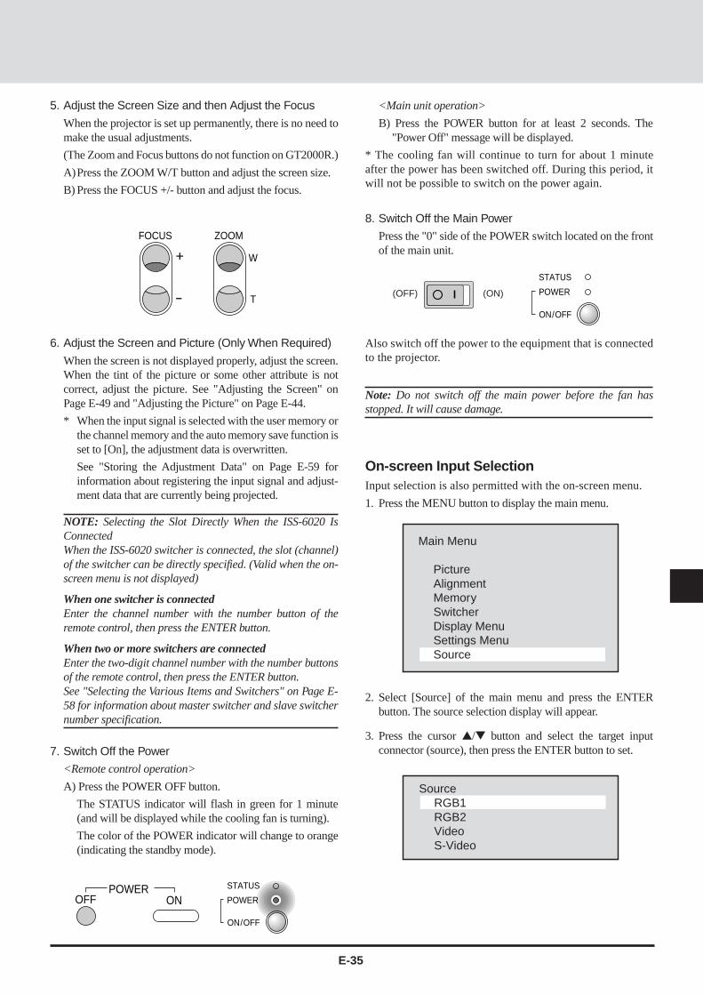
5. Adjust the Screen Size and then Adjust the Focus
When the projector is set up permanently, there is no need tomake the usual adjustments.
(The Zoom and Focus buttons do not function on GT2000R.)
A)Press the ZOOM W/T button and adjust the screen size.
B) Press the FOCUS +/- button and adjust the focus.
6. Adjust the Screen and Picture (Only When Required)
When the screen is not displayed properly, adjust the screen.When the tint of the picture or some other attribute is notcorrect, adjust the picture. See "Adjusting the Screen" onPage E-49 and "Adjusting the Picture" on Page E-44.
* When the input signal is selected with the user memory orthe channel memory and the auto memory save function isset to [On], the adjustment data is overwritten.
See "Storing the Adjustment Data" on Page E-59 forinformation about registering the input signal and adjust-ment data that are currently being projected.
NOTE: Selecting the Slot Directly When the ISS-6020 IsConnectedWhen the ISS-6020 switcher is connected, the slot (channel)of the switcher can be directly specified. (Valid when the on-screen menu is not displayed)
When one switcher is connectedEnter the channel number with the number button of theremote control, then press the ENTER button.
When two or more switchers are connectedEnter the two-digit channel number with the number buttonsof the remote control, then press the ENTER button.See "Selecting the Various Items and Switchers" on Page E-58 for information about master switcher and slave switchernumber specification.
7. Switch Off the Power
<Remote control operation>
A) Press the POWER OFF button.
The STATUS indicator will flash in green for 1 minute(and will be displayed while the cooling fan is turning).
The color of the POWER indicator will change to orange(indicating the standby mode).
<Main unit operation>
B) Press the POWER button for at least 2 seconds. The"Power Off" message will be displayed.
* The cooling fan will continue to turn for about 1 minuteafter the power has been switched off. During this period, itwill not be possible to switch on the power again.
8. Switch Off the Main Power
Press the "0" side of the POWER switch located on the frontof the main unit.
Also switch off the power to the equipment that is connectedto the projector.
Note: Do not switch off the main power before the fan hasstopped. It will cause damage.
Main Menu
PictureAlignmentMemorySwitcherDisplay MenuSettings MenuSource
SourceRGB1RGB2VideoS-Video
2. Select [Source] of the main menu and press the ENTERbutton. The source selection display will appear.
3. Press the cursor / button and select the target inputconnector (source), then press the ENTER button to set.
On-screen Input SelectionInput selection is also permitted with the on-screen menu.
1. Press the MENU button to display the main menu.

E-36
Main Menu
PictureAlignmentMemorySwitcherDisplay MenuSettings MenuSource
Settings Menu
LanguageBackgroundAuto StartAuto SaveOnscreen MuteSwitcher ControlExt. ControlProjector IDSync TerminationProjectionKeystoneKeystone Save
English Currently selecteditem
Setting at Time ofFactory Shipping
EnglishBlue backOffOffOffStandaloneOff00Hi-impedanceFront Floor00Off
Language
EnglishDeutschFrançaisItaliannoEspanolSvenska
SETUP (Various Settings)Please make settings in conjunction with both the projector and the system.
NOTE: To accommodate worldwide use of the projector, the default language setting for the projector is English. See below for thedetailed setting procedure. Descriptions given here assume that the language setting of the unit has already been set to English.
Default Settings of the Settings MenuThe unit is set as described below before it is shipped from the factory.
Please set any required items.
Press the MENU button to display [Main Menu], then select [Settings Menu] with the cursor button and press the ENTER buttonto display the various settings.
Selecting the On-screen Language[Language]This is the language selection for the display characters ofthe on-screen menu and other displays.
1. Select [Settings Menu] → [Language] from the main menu.
2. Press the cursor / button and select the language, thenpress the ENTER button to set.
To turn off the on-screen menu display, press theMENU button.
The display will return to the main menu. Press theMENU button again to turn off the on-screenmenu.

E-37
Background
BlueBlack
Auto Start
OnOff
Auto Save
OnOff
Onscreen Mute
OnOff
Selecting the Background Color When There IsNo Signal [Background]This is the setting of the background color when there is no inputsignal.
1. Select [Settings Menu] → [Background] from the main menu.
2. Press the cursor / button and select the background color, thenpress the ENTER button to set.
Blue...The background color will be blue.
Black...The background color will be black.
Selecting Auto Start [Auto Start]When the main power switch is set to ON, this function switcheson the power without the need to press the power button.
1. Select [Settings Menu] → [Auto Start] from the main menu.
2. Press the cursor / button and select On/Off, then press theENTER button to set.
On .... The projector will start up when the main power isswitched on.
Off .... The projector will enter the standby mode when themain power is switched on.
Selecting the Automatic Memory Save Function[Auto Save]This function automatically saves the adjustment conditions to thememory in use when screen adjustments or picture adjustments areperformed while projecting the image of the input equipment usinguser memory or channel memory.
The auto save function saves the information when the MENU andENTER buttons are used upon exiting from the various adjustmentmenus.
1. Select [Settings Menu] → [Auto Save] from the main menu.
2. Press the cursor / button and select On/Off, then press theENTER button to set.
On .... Auto memory saves are enabled.
Off .... Auto memory saves are disabled.
Selecting the On-screen Display ON/OFF[On-screen Mute]This is a selection of whether or not to show displays other than on-screen menu displays (such as simple condition displays, the ad-justment bar which is displayed when the remote control VOL-UME button is used to make an adjustment, and when switchingthe input signal).
1. Select [Settings Menu] → [On-screen Mute] from the main menu.
2. Press the cursor / button and select On/Off, then press theENTER button to set.
On .... Displays will be muted.
Off .... Displays will not be muted.

E-38
The term switcher refers to the NEC ISS-6020 Switcher.
Switcher Control
StandaloneSW 1 LevelSW 2 Level
Ext. Control
OnOff
Projector ID
No.0 - 64
Selecting the Switcher Control Method [SwitcherControl]The switcher is a unit that switches the input equipment when anumber of different video devices or computers are connected.
When the REMOTE 1 connector is used, input selection andadjustment are permitted by the projector. See "Using UserMemory and Channel Memory" on Page E-56.
See "(Connections with the ISS-6020)" on Page E-28 for informa-tion about connections.
1. Select [Settings Menu] → [Switcher Control] from the main menu.
2. Press the cursor / button and select the switcher connectioncondition, then press the ENTER button to set.
Settings will become effective the next time the power is switchedon.
Standalone ....... The projector used in stand alone opera-tion.
SW 1 Level ....... The projector used with one Switcher.
SW 2 Level ....... The projector used with two or moreSwitchers.
Selecting External Control Connections Settings[Ext. Control]When using the EXT-CTL connector of the projector, set theexternal control setting to [On].
1. Select [Settings Menu] → [Ext. Control] from the main menu.
2. Press the cursor / button and select On/Off, then press theENTER button to set.
On .... Enables the EXT-CTL connector.
Off .... Disables the EXT-CTL connector.
Setting the Projector ID Number [Projector ID]Set identification numbers to the projectors when operating anumber of projectors (GT2000/GT2000R) by remote control orwhen controlling a number of projectors by personal computer.
1. Select [Settings Menu] → [Projector ID] from the main menu.
2. Enter the ID number with the number buttons, then press theENTER button to set.
[00] will be set when using one projector.
When using a number of projectors, set [01] to [64].
• To delete the entry, press the CLEAR button of the remote control.The setting will return to [00].
When operating a number of projectors by remote control, also setthe address of the remote control. See "Setting of the RemoteControl Address" on Page E-43.
Setting the ID of the projector to [00] permits remote controloperation irrespective of the ID of the remote control.

E-39
Sync Termination
75ΩHi-Z
Projection
Front FloorRear CeilingRear FloorFront Ceiling
Sync Signal Termination Setting[Sync Termination]This sets the impedance of the RGB/YCbCr Input 1 connector.
This function sets whether or not the unit will accommodate a 75ohm output (specification) impedance of the video or personalcomputer equipment.
1. Select [Settings Menu] → [Sync Termination] from the mainmenu.
2. Press the cursor / button and select the termination resistancevalue, then press the ENTER button to set.
75 ohms........................... When the impedance of the out-put connector of the connectedequipment is 75 ohm.
High Impedance (Hi-Z) ..... When the impedance of the out-put connector of the connectedequipment is not 75 ohm.
To turn off the on-screen menu display, press the MENU button.The display will return to the main menu. Press the MENU buttonagain to turn off the on-screen menu.
Selecting the Projector’s Projection Method [Pro-jection]This selection of the projection method is made to suit the usageconditions.
Model GT2000 is designed for front projection and modelGT2000R is designed for rear projection.
1. Select [Settings Menu] → [Projection] from the main menu.
2. Press the cursor / button and select the target projection, thenpress the ENTER button to set.
Front floor .............. When the projector is placed on a tableand projects from the front
Rear ceiling ............ When the projector is suspended fromthe ceiling and projects from the rear
Rear floor ............... When the projector is placed on a tableand projects from the rear
Front ceiling ........... When the projector is suspended fromthe ceiling and projects from the front

E-40
[Keystone distortion] [No distortion]
Keystone Save
OnOff
Settings MenuLanguageBackgroundAuto StartAuto SaveOnscreen MuteSwithcer ControlExt. ControlProjector IDSync TerminationProjectionKeystoneKeystone Save
– + –10
Normalize?
Keystone
YesNo
Selecting Correction and Storage of KeystoneDistortion [Keystone]Keystone distortion arises when the angles are off between theprojector and screen in the vertical orientation at the time of settingup the projector. The keystone function is used in this distortionadjustment.
When the setting is permanent, setting the keystone save functionto On will enable projection using this adjustment value from thenext occasion.
• Adjusting Keystone Adjustment [Keystone]
1. Select [Settings Menu] → [Keystone] from the main menu.
The adjustment bar will be displayed.
2. Press the cursor § (–) / © (+) button and adjust so that the left andright sides are parallel.
NOTE: This function will not work when the input signal is notpresent. If this is the case, apply an signal and make the adjusment onit.
• Setting Keystone Save [Keystone Save]
1. Select [Settings Menu] → [Keystone Save] from the main menu.
2. Press the cursor / button and select On/Off, then press theENTER button to set.
On .... Enables the keystone correction value at startingtime.
Off .... Sets the keystone correction value to the defaultvalue at starting time.
To return to the default value, press the NORMAL button of theremote control.
Press the cursor / button and select [Yes], then press theENTER button to return to the default value.

E-41
The picture will become denser. (+ direc-tion)
The picture will become fainter. (- direc-tion)
CONTRAST
The adjustment range is from -31 to +32.
Contrast
– + ±0
The picture will become lighter. (+ direction)
The picture will become darker. (- direction)
The adjustment range is from -31 to +32.
Brightness
– + ±0
BRIGHT
ENTERNORMAL
Normalize?
Picture
YesNo
DISPLAY
SETUP
RGB1VGASource Lock :OffExpand :OnKeystone :On
Adjustments and Settings with the Remote ControlButtons (Direct Operation)
Functions can be called directly using the remote controlbuttons to make adjustments and settings (without the use ofthe on-screen menu display).
Adjustment of the PictureAdjustments can be made for the separate input sources(VIDEO, S-VIDEO, RGB1, and RGB2).
• Adjusting the contrast of the picture (Contrast)
• Adjusting the brightness of the picture (Brightness)
The picture adjustment data can be stored (i.e., saved) to thatmemory. See "Using User Memory and Channel Memory"on Page E-56.
• Returning to Standard Adjustments
Contrast and brightness will return to the standard settings.
This function is valid when the on-screen menu is not dis-played.
Press the NORMAL button. The verification display willappear. Press the ENTER button to set.
To cancel, press the cursor button, select [No], and pressthe ENTER button.
Display of Selected Input InformationThis displays the currently selected input information.
Press the DISPLAY button to show this information.
The information remains for 10 seconds.
Press the CLEAR button to delete this display.

E-42
CTL
DISPLAY
EXPAND
0
0
1
1
2
3
4
5
6
1 2 3 4 5 6 7 8 9 10 11 12 13 im)
im)
0
0
1
1
2
3
4
5
6
1 2 3 4 5 6 7 8 9 10 11 12 13 im)
im)
Digital Zoom OFF
Digital Zoom ON
Each press enlarges the pic-ture.
Each press reduces the pic-ture (toward the original size)
ZOOM
MAGNIFY/REDUCE
W
T
0
0
1
1
2
3
4
5
6
1 2 3 4 5 6 7 8 9 10 11 12 13 im)
im)
+-
2
3
4
5
6im)
Temporarily Turning Off the On-screen MenuDisplayThis function is used to temporarily turn off the on-screenmenu display.
This will be conveniently used when making fine picture orscreen adjustments while viewing the whole screen.
Hold down the CTL button and press the DISPLAY button.
This function will also be cancelled by pressing a buttonother than the cursor / button, but the operation of thebutton that is pressed will take effect.
Using Digital Zoom FunctionThe LCD panel of the projector has 136621024 pixels.
The digital zoom function converts input signals with resolu-tions of less than 136621024 pixels to a number of pixelsthat is close to 136621024 to provide an enlarged display.
A press of the EXPAND button results in a display thatcorresponds to the resolution of the input signal.
A further press returns the display to the original condition.
NOTE: When the Digital Zoom function is set to ON, the picturequality may deteriorate depending on the signal. The defaultsetting of Digital Zoom is ON. When the Digital Zoom functionis switched OFF, the Horizontal/Vertical amplitude and theKeystone adjustment are not available.
Using Digital EnlargementThis function can provide an enlarged display of up to 8times the size of a target portion. Hold down the CTL buttonand press the ZOOM button. To move the selected portion,use the cursor buttons.
CTL
The cursor buttons are used to move the screen position.

E-43
CTL
+
-
FOCUS
KEYSTONE
[Keystone distortion]
[No distortion]
AUDIOMUTE
PICTURE
ENTERSETUP
Adjusting Keystone DistortionKeystone distortion arises when the angles are off betweenthe projector and screen in the vertical orientation.
The keystone function is used in this distortion adjustment.
Hold the CTL button down and use the KEYSTONE +/-buttons to adjust the left and right sides so that they becomeparallel.
When the KEYSTONE item is set to [ON], this adjustmentcondition will take effect when the power is switched on. See"Selecting Keystone Distortion Correction and Storage" onPage E-40.
Temporarily Turning Off the Picture and Au-dioThis function is used to temporarily turn off the picture or theaudio.
Picture ......... A press of the PICTURE button will turnoff the picture. Another press will result inthe picture being projected.
Audio ........... A press of the AUDIO button will turn offthe audio. Another press will result in theaudio being output.
The background color of the screen will be black when thepicture is turned off.
Returning the RGB Input Signal to the Stan-dard AdjustmentThis function is used when something has gone wrong withthe screen at the time of RGB signal entry.
The function is valid when the on-screen menu is not beingdisplayed.
Press the SETUP button, then press the ENTER button.
Select an item from among the adjustment data stored to standardmemory that is close to the input signal.
When readjustment is necessary, adjust the screen or call up an itemthat is close to the input signal from within the user memory.
Upon a return to the standard adjustment, the YCbCr inputsetting becomes RGB input.
When a switcher is connected, the various items of theswitcher return to the default settings. (The sync terminationsetting will be high impedance.)
Memory SearchThis function is valid when the on-screen menu is not beingdisplayed.
Press the SETUP button, then press the LOAD button.
If you've modified the settings in memory, use this function.
Remote Control Address SettingWhen two or more projectors (GT2000/GT2000R) are usedwith wireless remote control operation, identification (ID) isgiven to the projectors and remote control so that otherprojectors are not controlled erroneously. Projectors havingthe same ID can be controlled.
A)Hold down the CTL button and press the Adr. button(VOLUME ). The address display appears.
Address
RC Unit 01
B) Use the number buttons to enter a 2-digit ID that is thesame as the ID of the projector that is being controlled.Addresses that can be specified are from 00 to 64.
Press the ENTER button to set.
When a mistake is made in the entry, press the CLEARbutton and start the entry again from Step A).
* The projector ID of the main unit can be checked with[Settings Menu] → [Projector ID] of the main menu.
* Setting the ID of the remote control to 00 permits remotecontrol operation irrespective of the ID of the projector.
* If the batteries are removed from the remote control, theremote ID will return to "00".

E-44
– + 0
Main Menu
PictureAlignmentMemorySwitcherDisplay MenuSettings MenuSource
Picture
BrightnessContrastVolumeColorTintSharpnessImage ModeWhite BalanceScan ModeInterpolationRGB/YCbCr
Contents of the selected itemare displayed.
Settings at the Time ofShipping from the Factory
Names of items that cannotbe adjusted with the cur-rently selected input modeare displayed in gray.
+-Change to the (–) direction Change to the (+) direction
The various adjustment ranges are from -31 to +32.
– + -10
Picture
BrightnessContrastVolumeColorTintSharpnessImage ModeWhite BalanceScan ModeInterpolationRGB/YCbCr
ADJUSTING THE PICTURE AND THE AUDIO (Picture)These functions adjust the picture and audio with the on-screen menu display.
When the input signal is selected with the user memory or the channel memory and the auto memory save function is set to [On],the adjustment data is overwritten.
Default Picture SettingsPicture settings at the time of shipping from the factory are as described below.
Please set required items.
Press the MENU button to display [Main Menu], select [Picture] with the cursor button, then press the ENTER button to displaythe picture.
Adjusting the Picture (Brightness, Contrast, Color, Tint, and Sharpness)Adjust these items to an optimum level in conjunction with the input image.
Select [Picture] from the main menu, then press the ENTER button.
When the item to be adjusted is selected, the adjustment bar of the selected item is displayed at the bottom edge of the display.
Normal
Auto
PC Mode
RGB

E-45
Item § (–) Button © (+) Button Notes
Brightness Becomes darker Becomes lighter ––––
Contrast Picture becomes fainter Picture becomes denser ––––
Color Color becomes paler Color becomes deeper RGB input does not
apply
Tint Becomes more reddish Becomes more greenish RGB, PAL and
SECAM input do not
apply
Sharpness Picture becomes softer Picture becomes more distinct RGB input does not
apply
White Balance
Brightness RBrightness GBrightness BContrast RContrast GContrast B
– + –10
+-Change to the (–) direction Change to the (+) direction
The various adjustment ranges are from -31 to +32.
Item Contents
Brightness R
Brightness G Adjustment of the black level of the picture
Brightness B
Contrast R
Contrast G Adjustment of the white level of the picture
Contrast B
– + 32
Picture
BrightnessContrastVolumeColorTintSharpnessImage ModeWhite BalanceScan ModeInterpolationRGB/YCbCr
Adjusting the White Balance (White Balance)This function corrects the black and white level of the input signaland adjusts the color reproducibility.
Select [Picture] --> [White Balance] from the main menu.
Adjusting the Volume (Volume)Select [Picture]→[Volume] from the main menu.
When the item to be adjusted is selected, the adjustment barof the selected item is displayed at the bottom edge of thedisplay.
Adjust the volume with the cursor § (–)/ © (+) buttons.
The adjustment range is from 0 to 63.

E-46
– + 0
Picture
BrightnessContrastVolumeColorTintSharpnessImage ModeWhite BalanceScan ModeInterpolationRGB/YCbCr
NORMAL ENTER
Normalize?
Contrast
YesNo
Image Mode
NormalNatural 1Natural 2Natural 3Doc Cam
Returning the Picture Adjustments to the Stan-dard SettingsThis function returns the adjustments of the selected items (i.e.,brightness, contrast, color, tint, sharpness, and white balance) tothe standard adjustments suited to the input mode.
Example: Returning the contrast to the standard setting.
Select [Picture]→[Contrast] from the main menu.
Press the NORMAL button. The verification display will appear.Press the ENTER button to set.
To cancel, press the cursor / button, select [No], then press theENTER button.
Selecting the Image Mode (Image Mode)These are the picture adjustment modes available with the projec-tor. Select the mode that is suited to personal computer text, or theprojected image of a video, etc.
Select [Picture]→[Image Mode] from the main menu.
Select the image mode with the cursor / button. Press theENTER button at the desired image mode.
Normal ......... This is set for RGB input.
Natural 1
Natural 2 This is set for natural pictures.
Natural 3
DOC CAM ... This is set for the use of a monitor camerawhen the screen is dark.

E-47
Scan Mode
AutoNon InterlaceInterlace VideoInterlace PC
Interpolation
PC ModeVideo Mode
Selecting the Scan Mode (Scan Mode)This function selects whether there is a skip to every other scan-ning line, or whether scanning lines are reproduced in order andprojected.
Select [Picture]→[Scan Mode] from the main menu.
Select the scan mode with the cursor / button, then press theENTER button.
Auto ...................... Automatic switching to suit the image.
Non Interlaced ...... Scanning lines are scanned in order toreproduce the image.
Suited for still pictures.
Interlaced Video ..... Every other scanning line in skipped toreproduce the image.
Suited for moving pictures.
Interlaced PC ........ Every other scanning line of the picture ofthe personal computer input is skipped toreproduce the image.
Selecting Smoothing (Interpolation)Select the item that suits the projected image of the personalcomputer or video signal, etc.
Select [Picture]→[Interpolation] from the main menu.
Select PC Mode or Video Mode with the cursor / button, thenpress the ENTER button.
PC Mode .............. Set this mode when importance is placedupon high-definition images such as withworkstations.
Video Mode .......... Set this mode when importance is placedupon natural pictures such as with videoimages.
NOTE: When a personal computer is selected and the Video Mode isset, the picture may be disturbed depending on the signal. Should thishappen, please use the PC Mode.
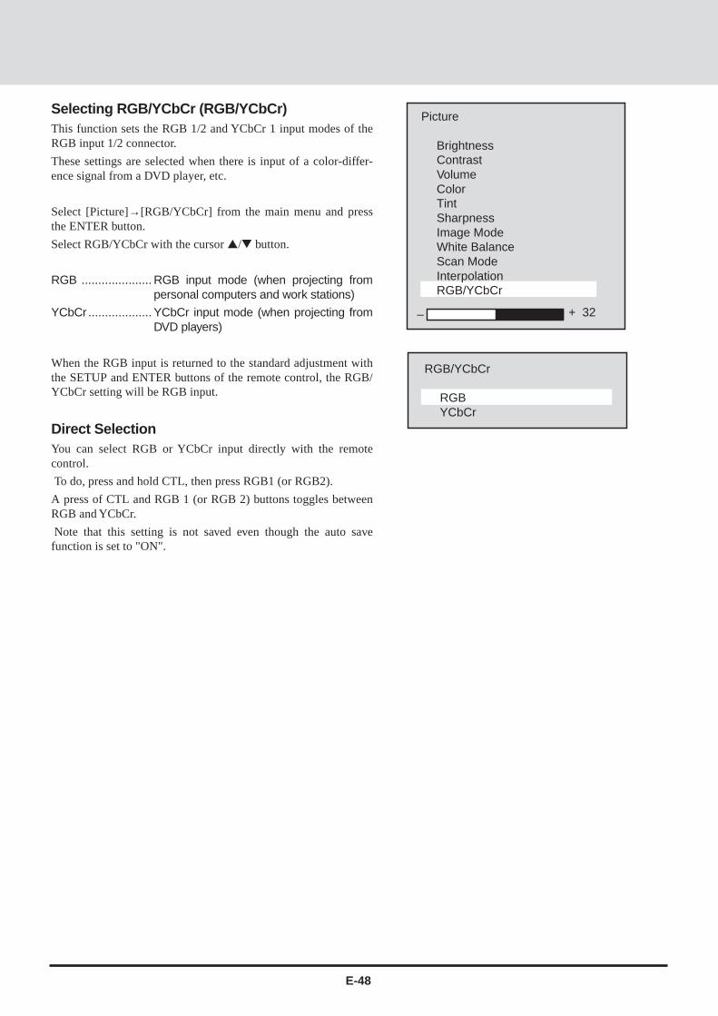
E-48
– + 32
Picture
BrightnessContrastVolumeColorTintSharpnessImage ModeWhite BalanceScan ModeInterpolationRGB/YCbCr
RGB/YCbCr
RGBYCbCr
Selecting RGB/YCbCr (RGB/YCbCr)This function sets the RGB 1/2 and YCbCr 1 input modes of theRGB input 1/2 connector.
These settings are selected when there is input of a color-differ-ence signal from a DVD player, etc.
Select [Picture]→[RGB/YCbCr] from the main menu and pressthe ENTER button.
Select RGB/YCbCr with the cursor / button.
RGB ..................... RGB input mode (when projecting frompersonal computers and work stations)
YCbCr ................... YCbCr input mode (when projecting fromDVD players)
When the RGB input is returned to the standard adjustment withthe SETUP and ENTER buttons of the remote control, the RGB/YCbCr setting will be RGB input.
Direct SelectionYou can select RGB or YCbCr input directly with the remotecontrol.
To do, press and hold CTL, then press RGB1 (or RGB2).
A press of CTL and RGB 1 (or RGB 2) buttons toggles betweenRGB and YCbCr.
Note that this setting is not saved even though the auto savefunction is set to "ON".
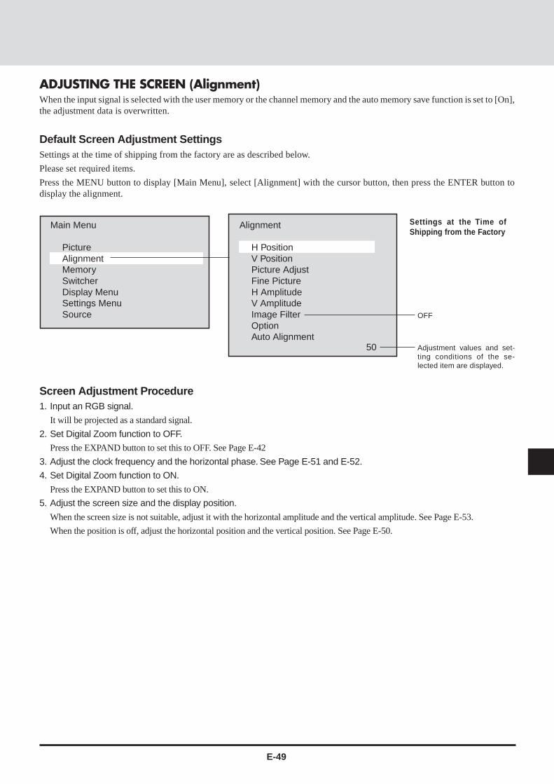
E-49
50
Main Menu
PictureAlignmentMemorySwitcherDisplay MenuSettings MenuSource
Alignment
H PositionV PositionPicture AdjustFine PictureH AmplitudeV AmplitudeImage FilterOptionAuto Alignment
Adjustment values and set-ting conditions of the se-lected item are displayed.
Settings at the Time ofShipping from the Factory
ADJUSTING THE SCREEN (Alignment)When the input signal is selected with the user memory or the channel memory and the auto memory save function is set to [On],the adjustment data is overwritten.
Default Screen Adjustment SettingsSettings at the time of shipping from the factory are as described below.
Please set required items.
Press the MENU button to display [Main Menu], select [Alignment] with the cursor button, then press the ENTER button todisplay the alignment.
Screen Adjustment Procedure1. Input an RGB signal.
It will be projected as a standard signal.
2. Set Digital Zoom function to OFF.
Press the EXPAND button to set this to OFF. See Page E-42
3. Adjust the clock frequency and the horizontal phase. See Page E-51 and E-52.
4. Set Digital Zoom function to ON.
Press the EXPAND button to set this to ON.
5. Adjust the screen size and the display position.
When the screen size is not suitable, adjust it with the horizontal amplitude and the vertical amplitude. See Page E-53.
When the position is off, adjust the horizontal position and the vertical position. See Page E-50.
OFF

E-50
0
0
1
1
2
3
4
5
6
1 2 3 4 5 6 7 8 9 10 11 12 13 im)
im)
0
0
1
1
2
3
4
5
6im)
0
0
1
1
2
3
4
5
6
1 2 3 4 5 6 7 8 9 10 11 12 13 im)
im)
0
0
1
1
2
3
4
5
6
1 2 3 4 5 6 7 8 9 10 11 12 13 im)
im)
0
0
1
1
2
3
4
5
6
1 2 3 4 5 6 7 8 9 10 11 12 13 im)
im)
50
Alignment
H PositionV PositionPicture AdjustFine PictureH AmplitudeV AmplitudeImage FilterOptionAuto Alignment
120
Alignment
H PositionV PositionPicture AdjustFine PictureH AmplitudeV AmplitudeImage FilterOptionAuto Alignment
Adjusting the Screen Position (Horizontal Position andVertical Position)• Adjusting the Horizontal Position
Select [Alignment]→[H Position] from the main menu.
When the item to be adjusted is selected, the adjustment value of the selecteditem is displayed at the bottom edge of the display.
Adjust the horizontal position with the cursor § (–)/ © (+) button.
The adjustment range will differ depending on the input signal.
Each press will move the horizontal position one pixel. Holding down thebutton will move the horizontal position continuously.
• Adjusting the Vertical Position
Select [Alignment]→ [V Position] from the main menu.
When the item to be adjusted is selected, the adjustment value of the selecteditem is displayed at the bottom edge of the display.
Adjust the vertical position with the cursor § (–)/ © (+) button.
The adjustment range will differ depending on the input signal.
Each press will move the vertical position one pixel. Holding down the buttonwill move the vertical position continuously.
Making Adjustments While Viewing the Entire Screen
Hold down the CTL button and press the DISPLAY button to temporarilyturn off the on-screen menu display. Now, only the cursor § (–)/ © (+)button will function. When another button is pressed, the menu will comeback on.

E-51
0
0
1
1
2
3
4
5
6
1 2 3 4 5 6 7 8 9 10 11 12 13 im)
im)
1420
Alignment
H PositionV PositionPicture AdjustFine PictureH AmplitudeV AmplitudeImage FilterOptionAuto Alignment
Adjusting the Horizontal Pixel Size and Phase (PictureAdjust and Fine Picture)Before making the adjustment, press the EXPAND button and turn OFF theDigital Zoom function.
Adjust the clock frequency, then adjust the horizontal position.
• Adjusting the Clock Frequency (Picture Adjust)
This function adjusts the pixel size of the computer and the pixel size of theLCD of the projector so that they become the same size.
Select [Alignment]→ [Picture Adjust] from the main menu.
When the item to be adjusted is selected, the adjustment value of the selecteditem is displayed at the bottom edge of the display.
Adjust the clock frequency with the cursor § (–) / © (+) button.
The optimum adjustment value is where the brightness of the screen becomesconstant (i.e., the bright and dark vertical bands disappear).
The adjustment range will differ depending on the input signal.
Holding down the button will change the clock frequency continuously. Fineadjustments can be made by single presses of the button.

E-52
0
0
1
1
2
3
4
5
6
1 2 3 4 5 6 7 8 9 10 11 12 13 im)
im)
183
Alignment
H PositionV PositionPicture AdjustFine PictureH AmplitudeV AmplitudeImage FilterOptionAuto Alignment
• Adjusting the Horizontal Phase (Fine Picture)
This function adjusts the phase of the pixels of the computer and the phase ofthe pixels of the LCD of the projector so that they are the same phase. Theadjustment is made to the point at which the screen color infidelity and flickerare at a minimum.
Select [Alignment] → [Fine Picture] from the main menu.
When the item to be adjusted is selected, the adjustment value of the selecteditem is displayed at the bottom edge of the display.
Adjust the horizontal phase with the cursor § (–)/ © (+) button.
The optimum adjustment value is where the screen color infidelity and flickerare at a minimum.
The adjustment range is from 0 to 255.
Holding down the button will change the horizontal phase continuously. Fineadjustments can be made by single presses of the button.
Making Adjustments While Viewing the Entire Screen
Hold down the CTL button and press the DISPLAY button to temporarily turnoff the on-screen menu display. Now, only the cursor § (–) / © (+) button willfunction. When another button is pressed, the menu will come back on.
Last press the EXPAND button and turn on the Digital Zoom function.

E-53
0
0
1
1
2
3
4
5
6
1 2 3 4 5 6 7 8 9 10 11 12 13 im)
im)
0
0
1
1
2
3
4
5
6
1 2 3 4 5 6 7 8 9 10 11 12 13 im)
im)
1368
Alignment
H PositionV PositionPicture AdjustFine PictureH AmplitudeV AmplitudeImage FilterOptionAuto Alignment
0
0
1
1
2
3
4
5
6
1 2 3 4 5 6 7 8 9 10 11 12 13 im)
im)
0
0
1
1
2
3
4
5
6
1 2 3 4 5 6 7 8 9 10 11 12 13 im)
im)
1024
Alignment
H PositionV PositionPicture AdjustFine PictureH AmplitudeV AmplitudeImage FilterOptionAuto Alignment
Changing the Display Size (Horizontal Amplitude and Ver-tical Amplitude)The projector already stores the standard personal computer and work stationresolutions in standard memory. When an RGB signal is input, the closestresolution is selected from among those stored and the signal is displayed.(When the information is stored in the user memory, it is searched from theuser memory.) It is for this reason that when the scanning frequency differsfrom the value of the standard memory, the display area or aspect ratio willalso differ. The horizontal magnification and vertical magnification are used toadjust this.
• Adjusting the Horizontal AmplitudeThis function adjusts the horizontal display size to suit the screen.
Select [Alignment] → [H Amplitude] from the main menu.
When the item to be adjusted is selected, the adjustment value of the selecteditem is displayed at the bottom edge of the display.
Adjust the horizontal amplitude with the cursor § (–)/ © (+) button.
The adjustment range will differ depending on the input signal.
Holding down the button will result in a continuous change. Fine adjustmentscan be made by single presses of the button.
• Adjusting the Vertical Amplitude
This function adjusts the vertical display size to suit the screen.
Select [Alignment] → [V Amplitude] from the main menu.
When the item to be adjusted is selected, the adjustment value of the selecteditem is displayed at the bottom edge of the display.
Adjust the vertical amplitude with the cursor § (–)/ © (+) button.
The adjustment range will differ depending on the input signal.
Holding down the button will result in a continuous change. Fine adjustmentscan be made by single presses of the button.
Change the horizontal or the vertical amplitude when the aspect ratio of thescreen differs from normal (i.e., a circle has become and ellipse).

E-54
0
0
1
1
2
3
4
5
6
1 2 3 4 5 6 7 8 9 10 11 12 13 im)
im)
0
0
1
1
2
3
4
5
6
1 2 3 4 5 6 7 8 9 10 11 12 13 im)
im)
Alignment
H PositionV PositionPicture AdjustFine PictureH AmplitudeV AmplitudeImage FilterOptionAuto Alignment
Filter
OnOff
Alignment
H PositionV PositionPicture AdjustFine PictureH AmplitudeV AmplitudeImage FilterOptionAuto Alignment
Option
V PhaseSkew CorrectionSync PositionClamp Timing
Option
V PhaseSkew CorrectionSync PositionClamp Timing
• Reducing Noise (Image Filter)
This function reduces video noise.
Select [Alignment] → [Image Filter] from the main menu, then press theENTER button. The image filter selection display will appear.
Select On/Off with the cursor / button.
On ........................ The low-pass filter is applied.
Off ........................ The filter is removed.
Screen adjustments are possible even when the filter is On.
Other Screen Adjustments (Vertical Phase, Skew Correc-tion, Sync Position, and Clamp Timing)Select [Alignment] → [Option] from the main menu, then press the ENTERbutton. The option menu will be displayed.
• Vertical Phase
This function adjusts the vertical pixel phase when an irregularity arises whilemaking fine vertical movements of the screen or in the interlaced display.
Select [V Phase] with the cursor / button.
When the item to be adjusted is selected, the adjustment value of the selecteditem is displayed at the bottom edge of the display.
Adjust to a normal condition with the cursor § (–)/ © (+) button.
The adjustment range is from 0 to 7.
• Skew Correction
This function adjusts the vertical bending of the screen.
Select [Skew Correction] with the cursor / button.
When the item to be adjusted is selected, the adjustment value of the selecteditem is displayed at the bottom edge of the display.
Adjust the bending with the cursor § (–)/ © (+) button.
The adjustment range is from 0 to 8.

E-55
0
0
1
1
2
3
4
5
6
1 2 3 4 5 6 7 8 9 10 11 12 13 im)
im)
• Sync Position
This function selects whether the leading edge or the trailing edge of thehorizontal sync pulse is set to the standard position (i.e., the PLL phase basisof comparison) and switches the sync position when jitter appears on thescreen.
Select [Sync Position] with the cursor / button.
When an item is selected, its adjustment values are indicated on the rightbottom of the menu.
While viewing the screen, select the item that results in the least distortionwith the cursor § (–)/ © (+) button.
The adjustment values are 0 or 1.
• Clamp Timing
This function sets the standard position of the black level of the picture and isused to set the level of screen brightness to an optimum level.
Select [Clamp Timing] with the cursor / button.
Selecting sync position moves the horizontal position. Adjust the horizontalposition.
While viewing the screen, select 0 or 1 with the cursor § (–)/ © (+) button.
Adjusting the Alignement Automatically (Auto Alignment)This function automatically adjusts the clock frequency, the horizontal/verticalposition and H/V amplitude.
Depending on the pattern, adjustment may not be possible.
Select [Alignment] → [Auto Alignment] from the main menu, then press theENTER button. The verification display will appear.
Select Yes/No with the cursor / button.
Repeat until an optimum screen is obtained.
NOTE: Automatic adjustment will not function with VIDEO or S-VIDEO input.When using RGB input, automatic adjustment will not function when NTSC, PAL/SECAM, or HDTV is input.
Option
V PhaseSkew CorrectionSync PositionClamp Timing
Option
V PhaseSkew CorrectionSync PositionClamp Timing
Alignment
H PositionV PositionPicture AdjustFine PictureH AmplitudeV AmplitudeImage FilterOptionAuto Alignment
Auto Alignment
OnOff

E-56
USING USER MEMORY ANDCHANNEL MEMORY (Memory)
Before Using the Memory FunctionThe projector uses a microprocessor to automatically iden-tify the input signal. Therefore, it is necessary to set and storein the microprocessor the adjustment conditions of such set-tings as the alignments and picture settings that match theinput signal and that an optimum picture can be reproduced.
The projector is equipped with five kinds of memory. Thereis standard memory that cannot be overwritten, user memoryto which the user can freely write or overwrite (and to whichswitcher channels can be registered), special switcher chan-nel memory that is used when this main unit and a number ofswitchers are connected and used together , the default areain a one-to-one correspondence with areas of the standardmemory, and last memory that stores the latest settings foreach source (RGB1, RGB2, Video, and S-Video)
Types of Memory• Standard Memory (Preset at Time of Shipping)
Video signals of the type used in personal computers andwork stations currently on the market have been registered inthe projector as standard data (and cannot be overwritten).See "Displayable Video Signals" on Page E-82.
When displaying personal computer video signals (resolu-tion/frequency) that have not been registered to standardmemory, make the screen and picture adjustments and thenregister them to user memory.
• User Memory
When data that has been adjusted by the user is stored to usermemory, it can be called back and used at any time.
A maximum of 100 items of screen and/or picture adjustmentor setting data can be registered.
• Channel Memory
This special memory for switchers is used to simultaneouslyregister the screen adjustment data and the data of theswitcher when the projector is used in conjunction with aswitcher.
A maximum of 100 channels (10 per switcher with max. of10 switchers) of setting data (for the various pieces of equip-ment that are connected to the switchers) and the screen andpicture adjustment data (adjusted by the projector) can beregistered.
• Default Area
This is a rewritable memory that is in a one-to-one corre-spondence with areas of the standard memory.
The projector searches the settings in the default area beforethe standard memory.
The factory shipped default area settings are the same as inthe standard memory.
• Last Memory
This is a memory that stores the last settings for each source(RGB1, RGB2, Video, and S-Video).
Switching sources will store the settings in memory. For thisreason, even if the memory is not used, returning to itsoriginal source will store the adjustments in memory.
Automatic Searches of MemoryThe channel memory is searched first when used with theswitcher (s).
When the input is switched, the projector searches the usermemory for the existence of applicable registration memoryduring input selection (of input source) or switcher slot selec-tion (RGB and RGB2 only). When more than one suchmemory item appear, the most recent memory number isselected. When there is no such memory item, the unitsearches irrespective of input selection or slot selection.When there is no applicable memory item in user memory,the default area and a standard memory search is performedin this order (but there will not be a search when there is askip setting).

E-57
Memory Selection and Item Contents
Selecting Memory DisplayThe user memory is displayed by pressing the MENU button and displaying [Main Menu], selecting [Memory] with the cursorbutton, and then pressing the ENTER button.
To switch between user memory and channel memory displays, hold down the CTL button and select with the cursor /button.
Switch pages with the cursor § (–)/ © (+) button. (There are 10 pages of user memory and 10 pages of channel memory.)
To display the list number selection and the registration menu, use the cursor / button to align the selection bar with thedesired list number, then press the ENTER button.
Main Menu
PictureAlignmentMemorySwitcherDisplay MenuSettings MenuSource
User MemoryP01/10
No Name Source Slot Lock00 CUTOM 0001 RGB1 Off010203 CUTOM 0004 S-VIDEO Off040506 CUTOM 0007 YCbCr1 On07 CUTOM 0008 RGB2 On0809 CUTOM 0010 VIDEO Off
Channel MemoryP01/10
No Name Source Lock00 CUTOM 0001 RGB1 Off010203 CUTOM 0004 S-VIDEO Off040506 CUTOM 0007 YCbCr1 On07 CUTOM 0008 RGB2 On0809 CUTOM 0010 VIDEO Off
Signal Entry
Entry CopyEntry MoveEntry DeleteChange DefalutMemory editLoadStore

E-58
Selecting the Various Items and Switchers• Selecting User Memory
No......................... List number
Name .................... Signal name entered by the user
Source .................. This is the set input mode.
(RGB 1, RGB 2, YCbCr1, YCbCr2, VIDEO, and S-VIDEO)
Slot ....................... This is the slot number of the channel. It is termed the channel in this manual.
User MemoryP01/10
No Name Source SlotLock00 CUTOM 0007 RGB1 04On01 CUTOM 0008 RGB2 07/08Off02
Currently selected page
Total number of pages
*
The [*] display appears when the skip setting is on.
07/08 indicates the selection of the equipment that is connected to the number 8 slot of
the master switcher, which is connected to the number 7 slot of the slave switcher.
04 indicates the selection of the equipment that is connected to the number 04 slot of the switcher.
Lock ...................... This is the on/off setting of the auto scan function at the time of input signal switching. It is selectedwith the edit menu.
• Selecting Channel Memory
In user memory, the slot specification differs.
Channel MemoryP01/10
No Name SourceLock00 CUTOM 0007 RGB1On01 CUTOM 0008 RGB2Off
Currently selected page
Total number of pages
In channel memory, the memory number becomes the channel number, which corresponds with the slot number of the switcher.
In signal registration, this number is selected and registration is made to this number.
Settings will differ depending on the switcher connection method. See "Changing the Slot Number of the Switcher (slot)Switcher Control" on Page E-67.
When the Setting is [SW 1 Level] (One Unit)
When the Setting is [SW 1 Level] (One Unit)
Channel numbers 10 through 19 correspond with switcher slot numbers 01 through 10. (Note that channel 10 will be slot 10, andchannel 11 will be slot 01.)
When the Setting is [SW 2 Level] (Two or More Units)
Channel numbers 00 through 09 correspond with slot numbers 1 through 10 of the slave switcher that is connected to slot 10 ofthe master switcher.
Channel numbers 10 through 19 correspond with slot numbers 1 through 10 of the slave switcher that is connected to slot 1 of themaster switcher.
Channel numbers 90 through 99 correspond with slot numbers 1 through 10 of the slave switcher that is connected to slot 9 of themaster switcher.

E-59
Storing the Adjustment Data (Store)
This function is used to store the screen and picture adjustment data currentlybeing projected.
The signal name and other data can be edited later.
1. Project the Picture of the Input Equipment
Select [Memory] → [User Memory] or [Channel Memory] from the mainmenu.
The user memory or channel memory will be displayed.
See "Selecting Memory Display" on Page E-57 for details.
2. Select the Number to Be Stored
Press the remote control / button and select the list number or the channelnumber, then press the ENTER button.
The display will change to the signal registration menu.
(When input selection and projection are conducted from the user memory orthe channel memory, the selection cursor will move to that number.)
3. Storing the Adjustment Data
1) Press the remote control / button, select [Store], then press the ENTERbutton.
The display will change to the store verification display.
2) Press the remote control / button, select Yes/No, then press the ENTERbutton.
* When a registered number is selected, the overwrite verification display willappear.
This ends the data storage procedure.
To turn off the display, press the MENU button. When the display has returnedto the main menu, press the MENU button again to turn off the display.
User MemoryP01/10
No Name Source Slot Lock00 CUTOM 0001 RGB1 Off010203 CUTOM 0004 S-VIDEO Off040506 CUTOM 0007 YCbCr1 On07 CUTOM 0008 RGB2 On0809 CUTOM 0010 VIDEO Off
User MemoryP01/10
No Name Source Slot Lock00 CUTOM 0001 RGB1 Off010203 CUTOM 0004 S-VIDEO Off040506 CUTOM 0007 YCbCr1 On07 CUTOM 0008 RGB2 On0809 CUTOM 0010 VIDEO Off
Signal EntryEntry CopyEntry MoveEntry DeleteChange DefalutMemory editLoadStore
Store?YesNo
Overwrite?YesNo

E-60
User MemoryP01/10
No Name Source Slot Lock00 CUTOM 0001 RGB1 Off010203 CUTOM 0004 S-VIDEO Off040506 CUTOM 0007 YCbCr1 On07 CUTOM 0008 RGB2 On0809 CUTOM 0010 VIDEO Off
Data Reading of Registration Signals (Load)
Adjustment and setting data are registered to suit the purpose of the externalequipment in the user memory and channel memory. This allows the input tobe switched and projected immediately when the projector is used in a systemor some other configuration. The desired adjustment and setting data can alsobe called without switching the input.
1. Displaying the Memory Display
Select [Memory] → [User Memory] or [Channel Memory] from the mainmenu.
The user memory or channel memory will be displayed.
See "Selecting Memory Display" on Page E-57 for details.
2. Select the Desired Number
Press the remote control / button and select the list number or the channelnumber, then press the ENTER button.
The display will change to the signal registration menu.
3. Retrieving the Signal Data
Press the remote control / button and select [Load].
Retrieving All the Data
Press the ENTER button.
The display will change to the load verification display.
Press the remote control / button, select Yes/No, then press the ENTERbutton.
Retrieving Data Other than Source Data
(Data is called without performing input switching.)
Hold down the CTL button and press the ENTER button.
The display will change to the data load verification display.
Press the remote control / button, select Yes/No, then press the ENTERbutton.
This ends the data retrieving procedure.
At this time, auto search during input signal switching will be invalid. (Lock Oncondition.)
User MemoryP01/10
No Name Source Slot Lock00 CUTOM 0001 RGB1 Off010203 CUTOM 0004 S-VIDEO Off040506 CUTOM 0007 YCbCr1 On07 CUTOM 0008 RGB2 On0809 CUTOM 0010 VIDEO Off
Signal EntryEntry CopyEntry MoveEntry DeleteChange DefalutMemory editLoadStore
Load?YesNo
Data Load?YesNo

E-61
Copying All the Data (Entry Copy)This function copies the registered signal data (i.e., the copy source) to theselected number (i.e., the copy destination).
1. Displaying the Signal Registration Menu Display
Select [Memory] → [User Memory] or [Channel Memory] from the mainmenu, then press the ENTER button.
The signal registration menu display will appear.
See "Selecting Memory Display" on Page E-57 for details.
2. Copying
Press the remote control / button and select [Entry Copy], then press theENTER button.
The display will change to the user memory or the channel memory display.
"Copy: Copy Source Selection" will appear at the bottom of the display.
1) Press the remote control / button and select the copy source number,then press the ENTER button.
"Copy: Copy Destination Selection" will appear at the bottom of the display.
2) Press the remote control / button and select the copy destination number,then press the ENTER button.
When the signal data has already been registered to the copy destination, theverification display will appear. Press the remote control / button andselect Yes/No, then press the ENTER button.
This ends the copy procedure.
To turn off the display, press the MENU button. The display will return to themain menu. A further press of the MENU button will turn off the display.
Signal Entry
Entry CopyEntry MoveEntry DeleteChange DefalutMemory editLoadStore
User MemoryP01/10
No Name Source Slot Lock00 CUTOM 0001 RGB1 Off010203 CUTOM 0004 S-VIDEO Off040506 CUTOM 0007 YCbCr1 On07 CUTOM 0008 RGB2 On0809 CUTOM 0010 VIDEO OffEntry Copy: Select Source
User MemoryP01/10
No Name Source Slot Lock00 CUTOM 0001 RGB1 Off0102
User MemoryP01/10No Name Source Slot Lock00 CUTOM 0001 RGB1 Off01 CUTOM 0007 YCbCr1 On02
Overwrite?
YesNo

E-62
Signal EntryEntry CopyEntry MoveEntry DeleteChange DefalutMemory editLoadStore
User MemoryP01/10
No Name Source Slot Lock00 CUTOM 0001 RGB1 Off010203 CUTOM 0004 S-VIDEO Off040506 CUTOM 0007 YCbCr1 On07 CUTOM 0008 RGB2 On0809 CUTOM 0010 VIDEO OffEntry Move: Select Source
User MemoryP01/10
No Name Source Slot Lock00 CUTOM 0001 RGB1 Off0102
User MemoryP01/10No Name Source Slot Lock00 CUTOM 0001 RGB1 Off01 CUTOM 0007 YCbCr1 On0203 CUTOM 0004 S-VIDEO Off04050607 CUTOM 0008 RGB2 On0809 CUTOM 0010 VIDEO Off
Overwrite?
YesNo
Moving Data (Entry Move)This function moves the registered signal data (i.e., the move source) to theselected number (i.e., the move destination).
1. Displaying the Signal Registration Menu Display
Select [Memory] → [User Memory] or [Channel Memory] from the mainmenu, then press the ENTER button.
The signal registration menu display will appear.
See "Selecting Memory Display" on Page E-57 for details.
2. Moving
Press the remote control / button and select [Entry Move], then press theENTER button.
The display will change to the user memory or the channel memory display.
"Move: Move Source Selection" will appear at the bottom of the display.
1) Press the remote control / button and select the move source number,then press the ENTER button.
"Move: Move Destination Selection" will appear at the bottom of thedisplay.
2) Press the remote control / button and select the move destinationnumber, then press the ENTER button.
When the signal data has already been registered to the move destination, theverification display will appear. Press the remote control / button andselect Yes/No, then press the ENTER button.
This ends the move procedure.
To turn off the display, press the MENU button. The display will return to themain menu. A further press of the MENU button will turn off the display.

E-63
Deleting a Range of Data (Entry Delete)This function specifies the range that is to be deleted and deletes the signaldata.
1. Displaying the Signal Registration Menu Display
Select [Memory] → [User Memory] or [Channel Memory] from the mainmenu, then press the ENTER button.
The signal registration menu display will appear.
See "Selecting Memory Display" on Page E-57 for details.
2. Deleting
Press the remote control / button and select [Entry Delete], then press theENTER button.
The display will change to the user memory or the channel memory display.
"Delete: Starting No. Selection" will appear at the bottom of the display.
1) Press the remote control / button and select the starting number of thedeletion, then press the ENTER button.
"Delete: Ending No. Selection" will appear at the bottom of the display.
2) Press the remote control / button and select the ending number of thedeletion, then press the ENTER button.
When only one digit is to be deleted, just press the ENTER button.
A verification display to the effect of Delete? will appear. Press the remotecontrol / button and select Yes/No, then press the ENTER button.
This ends the deletion procedure.
To turn off the display, press the MENU button. The display will return to themain menu. A further press of the MENU button will turn off the display.
Signal EntryEntry CopyEntry MoveEntry DeleteChange DefalutMemory editLoadStore
User MemoryP01/10
No Name Source Slot Lock00 CUTOM 0001 RGB1 Off010203 CUTOM 0004 S-VIDEO Off040506 CUTOM 0007 YCbCr1 On07 CUTOM 0008 RGB2On0809 CUTOM 0010 VIDEO OffDelete: Select Start Line
User MemoryP01/10No Name Source Slot Lock00 CUTOM 0001 RGB1 Off010203 CUTOM 0004 S-VIDEO Off040506 CUTOM 0007 YCbCr1 On07 CUTOM 0008 RGB2 On0809 CUTOM 0010 VIDEO OffDelete: Select End Line
User MemoryP01/10No Name Source Slot Lock00010203040506 CUTOM 0007 YCbCr1 On07 CUTOM 0008 RGB2 On0809 CUTOM 0010 VIDEO Off
Delete?NO. 00-03
YesNo

E-64
Changing the Default Values of the Screen Data (ChangeDefault)The projector is equipped with default area that stores screen data having aone- to - one correspondence with the standard memory. At the start, thismemory contains the screen data of the standard memory.
When the display area of the personal computer that is being projected with thestandard memory is not normal, the correct screen data can be written to thedefault area.
1. Projecting Input Signals that Are to Be Default Values
Input the signal of the computer and adjust the screen to a proper screen.
This will be the default value of the screen data at this resolution.
2. Displaying the Signal Registration Menu Display
Select [Memory] → [User Memory] or [Channel Memory] from the mainmenu, then press the ENTER button.
The signal registration menu display will appear.
See "Selecting Memory Display" on Page E-57 for details.
3. Changing the Default Values of the Screen Data
1) Press the remote control / button and select [Change Default], then pressthe ENTER button.
The default change verification display will appear.
2) Press the remote control / button and select the Yes/No, then press theENTER button.
The defaults have now been changed.
To turn off the display, press the MENU button twice. The display will returnto the main menu. A further press of the MENU button will turn off the display.
To initialize the default area (or to become the same as the standard memory)
1) Press the NORMAL button.
2) Press the remote control / button and select the Yes/No, press the ENTERbutton.
The default area has now been returned to its original factory settings.
Signal EntryEntry CopyEntry MoveEntry DeleteChange DefalutMemory editLoadStore
Normalize?Change DefalutYesNo

E-65
Editing the Memory Contents (Source Edit)
This function edits the registration contents of the user memory and thechannel memory.
Skip and Source lock settings are made with Source Edit.
Note: The changes you make to the memory contents will take effect at the nexttime you use the memory.
Preparations Prior to Editing and Closing the Editing1) Select the Memory Number to Be Edited
Select [Memory] → [User Memory] or [Channel Memory] from the mainmenu.
Press the cursor / button and select the memory number that is to be edited,then press the ENTER button.
The signal registration menu display will appear.
2) Display the Editing Menu
Press the cursor / button and select [Source Edit], then press the ENTERbutton.
Display the edit menu.
Advance to the desired item.
3) Turn Off the On-screen Menu Display
To turn off the display, press the MENU button 3 times. The display will returnto the main menu.
Press the button once more to turn off the display.
* Changing the Signal Name (Name)
1) Select [Source Edit] → [Name], then press the ENTER button.
The name entry display will appear.
2) Change the Name
Use the remote control cursor § (–)/ © (+) button to align the cursor with thecharacter that is to be changed, then use the remote control number buttons toselect the character.
(To cancel, press the MENU button.)
Press the ENTER button when the change has been completed.
The display will return to the editing menu.
User MemoryP01/10No Name Source Slot Lock00 CUTOM 0001 RGB1 Off01
Signal EntryEntry CopyEntry MoveEntry DeleteChange DefalutMemory editLoadStore
Memory editNameSlotImage ModeSkipSource LockSync Termination
CUSTOM0001
Memory editNameSlotImage ModeSkipSource LockSync Termination
CUSTOM0001
Name InputCUSTOM0001

E-66
Signal Name Entry Method
Select [Source Edit] → [Name], then press the ENTER button to change to thesignal name entry display.
Here, the character entry and deletion methods will be described.
A maximum of 10 characters can be entered for the signal name.
Use the remote control number buttons and CTL button to enter the letters.
Example: Enter XGA
1) Enter X. (X is on the 8 button.)
Each press of the 8 button moves the selection through the sequence ofV→W→X→8 which repeats. Select X. To enter lower case and other charac-ters, hold down the CTL button and select the characters.
2) Use the cursor / button to move the cursor to the next position.
Enter G and A using the same method as in Step 1).
* If a mistake is made, use the cursor / button to align the cursor with theerror, select the character, and correct it. To delete a character, press the CLEARbutton.
3) Press the ENTER button to set.
Name Input
Name InputX
Name InputX
Name InputXGA
Name InputXG
Correrspondence Table for Number Buttons and Letters
Number Buttons Press Directly Used with CTL
1 ABC1 a b
c !
2 DEF2 d e
f ” 3 GHI3
g h i #
4 JKL4 j k l
$
5 MNO5 m n o %
6 PQR6 p q
r &
7 STU7 s t
u ’
8 VWX8 v w x (
9 YZ?9 y z
/ )
0 * , . 0

E-67
Changing the Slot Number of the Switcher (Slot)The slot number can be changed with user memory when the source setting isRGB 1 / YCbCr 1 or RGB 2 / YCbCr 2.
1) Select [Source Edit] → [Slot], then press the ENTER button.
The switcher control display will appear.
2) Change the Switcher Control Condition
Press the cursor / button and select the slot number, then press the ENTERbutton.
The display will change to the slot master display.
When [Standalone] is selected, the display returns to the editing menu.
3) Changing the Slot
Press the cursor / button and select the slot number, then press the ENTERbutton.
The display will change to the slot slave display.
When [SW 1 Level] (one unit) is selected, the display will return to the editingmenu.
Press the cursor / button and select the slot slave number, then press theENTER button.
The display will return to the editing menu.
Changing the Image Mode (Image)Select [Source Edit] → [Image], then press the ENTER button.
The image mode display will appear. See "Selecting the Image Mode" on PageE-46.
Setting the Skip (Skip)When the input signal is switched, the unit automatically performs a memorysearch.
When a list number that you wish to skip has been set, the unit will skip over it.
1) Select [Source Edit] → [Skip], then press the ENTER button.
The skip display will appear.
2) Setting the Skip
Press the cursor / button and select On/Off.
On .... The setting will be beyond the object of the search. The line ismarked with an asterisk (*).
Off .... The setting will be the object of the search.
(To cancel, press the MENU button.)
Press the ENTER button.
The display will return to the edit menu.
Memory editNameSlotImage ModeSkipSource LockSync Termination
Switcher ControlStandaloneSW 1 LevelSW 2 Level
Slot MasterSlot-01Slot-02
Slot SlaveSlot-01Slot-02
Memory editNameSlotImage ModeSkipSource LockSync Termination
SkipOnOff

E-68
Setting Auto Search Forced Lock (Source Lock)When the input signal is switched, the unit automatically performs a memorysearch.
This setting mandatorily invalidates auto search.
1) Select [Source Edit] → [Source Lock], then press the ENTER button.
The source lock display will appear.
2) Setting the Source Lock
Press the cursor / button and select On/Off.
On .... Auto search will be invalidated.
(Auto search will not be performed even when the input signalchanges.)
Off .... Auto search will be effective. (Normal)
(To cancel, press the MENU button.)
Press the ENTER button.
The display will return to the edit menu.
Sync Signal Termination Setting (Sync Termination)This sets the termination resistance for the input sync of the RGB1/YCbCr1Input connector.
Select [Source Edit]→ [Sync], then press the ENTER button.
The sync termination display appears. See "Sync Signal Termination Setting"on Page E-39.
Memory editNameSlotImage ModeSkipSource LockSync Termination
Source Lock
OnOff

E-69
Viewing the Details of the Input Signal (Display Menu)
This function is convenient for checking the condition of the signal that iscurrently being input.
Select [Display Menu] from the main menu and press the ENTER button.
The display will change to the Display menu.
Press the remote control / button to select [Input Signal], then press theENTER button.
The details of the input signal will be displayed.
To turn off the display, press the MENU button. The display will return to theprevious menu.
Press the MENU button from the main display to turn off the display.
Memory number.... This is the list number or channel number of the userregistration, channel registration, the standardmemory, and the default are:
S : Standard memory, U : Default area, U : Usermemory, C : Channel memory
Horizontal
frequency .............. This is the horizontal scanning frequency.
Vertical
frequency .............. This is the vertical scanning frequency.
Pixel Clock ............ This is the clock frequency.
Sync Polarity ......... This is the polarity of the horizontal sync signal and thevertical sync signal.
Default Area .......... This is the location number where the default data isstored.
Resolution ............. This is the horizontal and vertical resolution for thecurrently displayed signal.
Scan Mode ........... This is the currently selected scan mode.
Main MenuPictureAlignmentMemorySwitcherDisplay MenuSettings MenuSource
DisplayLamp UsageInput Signal
Input SignalMemory No. U--00Frequency fH 37.5kHzFrequency fV 75HzPixel Clock30.0MHzSync Polarity HD(-) VD(-)Default Area 06Resolution6402480Scan Mode Non In-terlace
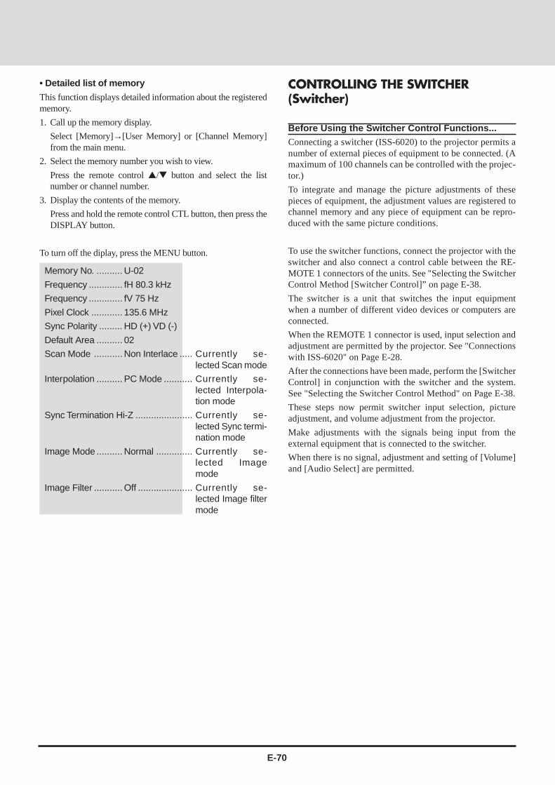
E-70
• Detailed list of memory
This function displays detailed information about the registeredmemory.
1. Call up the memory display.
Select [Memory]→[User Memory] or [Channel Memory]from the main menu.
2. Select the memory number you wish to view.
Press the remote control / button and select the listnumber or channel number.
3. Display the contents of the memory.
Press and hold the remote control CTL button, then press theDISPLAY button.
To turn off the diplay, press the MENU button.
CONTROLLING THE SWITCHER(Switcher)
Before Using the Switcher Control Functions...Connecting a switcher (ISS-6020) to the projector permits anumber of external pieces of equipment to be connected. (Amaximum of 100 channels can be controlled with the projec-tor.)
To integrate and manage the picture adjustments of thesepieces of equipment, the adjustment values are registered tochannel memory and any piece of equipment can be repro-duced with the same picture conditions.
To use the switcher functions, connect the projector with theswitcher and also connect a control cable between the RE-MOTE 1 connectors of the units. See "Selecting the SwitcherControl Method [Switcher Control]” on page E-38.
The switcher is a unit that switches the input equipmentwhen a number of different video devices or computers areconnected.
When the REMOTE 1 connector is used, input selection andadjustment are permitted by the projector. See "Connectionswith ISS-6020" on Page E-28.
After the connections have been made, perform the [SwitcherControl] in conjunction with the switcher and the system.See "Selecting the Switcher Control Method" on Page E-38.
These steps now permit switcher input selection, pictureadjustment, and volume adjustment from the projector.
Make adjustments with the signals being input from theexternal equipment that is connected to the switcher.
When there is no signal, adjustment and setting of [Volume]and [Audio Select] are permitted.
Memory No. .......... U-02
Frequency ............. fH 80.3 kHz
Frequency ............. fV 75 Hz
Pixel Clock ............ 135.6 MHz
Sync Polarity ......... HD (+) VD (-)
Default Area .......... 02
Scan Mode ........... Non Interlace ..... Currently se-lected Scan mode
Interpolation .......... PC Mode ........... Currently se-lected Interpola-tion mode
Sync Termination Hi-Z ...................... Currently se-lected Sync termi-nation mode
Image Mode .......... Normal .............. Currently se-lected Imagemode
Image Filter ........... Off ..................... Currently se-lected Image filtermode

E-71
Default Settings of the SwitcherPicture settings at the time of shipping from the factory are as described below.
Please adjust and set required items.
Press the MENU button to display [Main Menu], select [Switcher] with thecursor button, then press the ENTER button to display the switcher menu.
Main MenuPictureAlignmentMemorySwitcherDisplay MenuSettings MenuSource
SwitcherR GainG GainB GainColorTintSharpnessVolumeAudio Select
– +
Switcher Picture Adjustment
Select [Switcher] from the main menu.
Press the cursor / button and select the adjustment item.
When the item to be adjusted is selected, the adjustment bar of the selecteditem is displayed at the bottom edge of the display.
Adjust with the cursor § (–)/ © (+) button.
Returning the Picture Adjustment to the Standard Set-tingsThis function returns the adjustments of the R, G, and B gains, the color, tint,and sharpness to the standard settings.
Example: Return the R Gain to the Standard Setting.
Press the cursor / button and select [R Gain].
When the item to be adjusted is selected, the adjustment bar of the selecteditem is displayed at the bottom edge of the display.
Press the NORMAL button. A verification display “Normalize ?” will appear.Press the cursor / button, select Yes/No, then press the ENTER button.
The setting will return to the factory setting value of the switcher.
SwitcherR GainG GainB GainColorTintSharpnessVolumeAudio Select
– +32
SwitcherR GainG GainB GainColorTintSharpnessVolumeAudio Select
– +32
Normalize?YesNo
Setting at the time of shippingfrom the factory is ‘Projector”.

E-72
Audio Control of the Switcher
This is the audio adjustment of the switcher AUDIO OUTPUT.
Setting the Volume (Volume)This function sets the volume adjustment data that corresponds to the slot.
Select [Switcher] from the main menu.
Press the cursor / button and select [Volume].
When the item to be adjusted is selected, the adjustment bar of the selecteditem is displayed at the bottom edge of the display.
Adjust with the cursor § (–)/ © (+) button.
The adjustment range is from 0 to 63.
(–) Direction .......... The volume decreases.
(+) Direction .......... The volume increases.
Adjusting Volume of Switcher with Remote Control (AudioSelect)This is a setting that adjusts the volume of the switcher with the VOLUMEbutton on the remote control.
Select [Switcher] → [Audio Select] of the main menu.
When the item to be adjusted is selected, the setting condition is displayed atthe bottom edge of the display.
A press of the ENTER button changes the display to the audio control display.
Press the cursor / button and select Switcher / Remote control.
Switcher ................ Permits volume adjustment of the switcher using theVOLUME button of the remote control.
Projector ............... Permits volume adjustment of the projector using theVOLUME button of the remote control.
* The Switcher menu displays only when the switcher is connected with theGT2000/GT2000R and Switcher Control mode is set to either SW 1 Level orSW 2 Level.
Note:When the switcher is not connected, "Switcher" cannot be selected.
SwitcherR GainG GainB GainColorTintSharpnessVolumeAudio SelectProjector
SwitcherR GainG GainB GainColorTintSharpnessVolumeAudio Select
– +32

E-73
5 MAINTENANCEStep 1
Step 2
Step 3
Step 4
Step 5
This section describes the simple maintenance procedures you should followto replace the lamp, clean or replace the filter, and replace the batteries in theremote control.
Replacing The LampAfter your lamp has been operating for 2000 hours or longer, the red“status” light in the cabinet will go on and the lamp icon will appear onthe above right of the screen whenever the projector is turned on. Thelamp icon remains on after 2100 hours of service. Even though the lampmay still be working, replace it at 2000 hours to maintain optimal projec-tor performance.
CAUTION• DO NOT TOUCH THE LAMP immediately after it has been used. It will be
extremely hot. Allow at least one hour for the lamp to cool beforehandling.
• DO NOT REMOVE ANY SCREWS except the lamp cover set screw andtwo lamp case screws. You could receive an electric shock.
• Do not touch the front surface portion of the replacement lamp body inwhich glass is used.Touching the glass portion or bulb tip may result in a drop of thebrightness or shortened bulb life.
• Turn off the main power to the projector and disconnect the power cord.Allow at least one hour for the lamp to cool.
• If you continue to use the lamp after 2000 hours of use, the lamp bulb mayshatter, and pieces of glass may be scattered in the lamp case. Do nottouch them as the pieces of glass may cause injury. If this happens,contact your NEC dealer for lamp replacement.
To replace the lamp:1. Loosen the single captive screw that secures the lamp housing cover and
remove the cover.2. Loosen the two captive screws securing the lamp case.3. Remove the lamp by pulling out the complete assembly.4. Install a new lamp case assembly and secure it in place with the two
captive screws.
CAUTION: Do not use a lamp other than the NEC replacement lamp.Order this from your NEC dealer using your projector's model number.
5. Reattach the lamp housing cover and tighten the single captive screw.6. After you install a new lamp, select [Display] from the main menu, and press
the ENTER button. Then press the remote / button to select [LampUsage], then press the NORMAL button to display the Reset menu. Press theremote / button to select [Yes] and press the ENTER button.This resets the lamp clock back to zero.
Note: When you replace the lamp, it is also wise to replace the filter. Thefilter comes in the same package with your replacement lamp.
To check and reset the lamp usage time
To view the lamp usage time:1. Select [Display Menu] from the main menu and press the ENTER button.2. Press the remote / button to select [Lamp Usage].
The usage time will be displayed at the bottom right of the menu.
Note: After your lamp has been operating for 2000, a warning icon willappear.
To reset the lamp clock back to zero:1. Select [Display] from the main menu, and press the ENTER button.2. Press the remote / button to select [Lamp Usage], then press the
NORMAL button.3.Press the remote / button to select [Yes] and press the ENTER button.
This resets the lamp clock back to zero. Also the STATUS indicator goes off.
MEMU
SELECT
ZOOMFOCUS
STATUS
POWER
ON / OFF
ENTER
MEMU
SELECT
ZOOMFOCUS
STATUS
POWER
ON / OFF
ENTER
MEMU
SELECT
ZOOMFOCUS
STATUS
POWER
ON / OFF
ENTER
MEMU
SELECT
ZOOMFOCUS
STATUS
POWER
ON / OFF
ENTER
MEMU
SELECT
ZOOMFOCUS
STATUS
POWER
ON / OFF
ENTER
Lamp housing cover
Captive screw
Interlock
Captive screw

E-74
Cleaning Or Replacing The FilterThe air-filter sponge keeps the inside of the MultiSync GT2000/GT2000R LCD Projector free from dust or dirt and should becleaned after every 100 hours of operation (more often in dustyconditions). If the filter is dirty or clogged, your projector mayoverheat.
NOTE: Clean your filter after every 100 hours of operation.
CAUTION• Turn off the main power and unplug the projector before
replacing the filter.
• Only clean the outside of the filter cover with a vacuumcleaner.
• Do not attempt to operate the projector without a filtercover.
• Your LCD projector will not operate unless the filter coveris installed correctly.
To clean the air-filter:Vacuum the filter through the filter cover.To replace the air-filter:1. Remove the filter cover by pushing up on the catch of the
cover until you feel it detach.2. Reinstall the new filter cover.
NOTE: Do not detach the sponge from the filter cover. Do notwash the filter cover with soap and water. Soap andwater will damage the filter membrane.Before replacing the filter cover, remove dust and dirtfrom the projector cabinet. Keep out dust and dirtduring filter replacement.
Remote Control Battery Installation
AC IN
MENU
SELECT
ENTER
STATUSZOOM
FOCUS
POWER
ON / OFF
-
+
-
+-
+
AC IN
MENU
SELECT
ENTER
STATUSZOOM
FOCUS
POWER
ON / OFF
-
+
-
+-
+
Installing the Remote Control BatteriesWhen it comes time to replace the batteries, two "AAA" type
will be required.
1. Press and open the cover.
2. Align the batteries according to the (+) and (-)
indications inside the case.
3. Replace the cover.

E-75
Etape 1
Etape 2
Etape 3
Etape 4
Etape 5
Cette section décrit les procédures simples d’entretien que vous aurez à suivrepour remplacer la lampe, nettoyer ou remplacer le filtre et remplacer les pilesde la télécommande.
Remplacement de la lampeLorsque la lampe a été utilisée pendant 2000 heures ou plus, le voyant“Status” (état) du coffret s’allume. Même si la lampe peut encorefonctionner, remplacez-la au bout de 2000 heures pour conserver uneperformance optimale de votre projecteur.
PRECAUTION• NE TOUCHEZ PAS A LA LAMPE juste après qu’elle a été utilisée. Elle
est très chaude. Laissez-la refoidir pendant au moins une heure avant dela manipuler..
• NE RETIREZ AUCUNE VIS mis à part la vis qui fixe le couvercle delampe et les deux vis du compartiment de lampe. Vous risquez derecevoir une décharge éléctrique.
• Mettez le projecteur hors circuit et débranchez le cordon d’alimentation.Laissez refroidir la lampe pendant au moins une heure.
• Le projecteur s’éteindra et restera en attente après 2100 heuresd’utilisation. Dans ce cas, remplacez la lampe. Si vous continuezd’utiliser la lampe après 2000 heures d’utilisation, l’ampoule peut sebriser et des brisures de verre peuvent être éparpillées dans lecompartiment de la lampe. Ne les touchez pas car elles peuvent vousblesser. Dans ce cas, contactez votre revendeur NEC afin de procéder auremplacement de la lampe.
Pour remplacer la lampe:1. Retirez l’unique vis qui fixe le couvercle de lampe et retirez le couvercle
2. Retirez les deux vis qui fixent le compartiment de lampe. (Afin deprévenir contre un risque de décharge électrique, il y a un enclenchementsur ce compartiment. Ne tentez pas de détourner cet enclenchement.)
3. Retirez la lampe en tirant tout l’assemblage.
4. Installez un nouvel assemblage de compartiment lampe et fixez-le avec lesdeux vis.
PRECAUTION: N’utilisez pas d’autres lampes qu’une lampe de rechangeNECCommandez-la auprès de votre vendeur NEC en donnant le numéro demodèle du projecteur.
5. Fixez de nouveau le couvercle de lampe et replacez la vis unique.
6. Une fois la nouvelle lampe installée.
REMARQUE: Réinitialiser la durée totale d’ usage de lampe. (Se rperorterà la page E-73.)REMARQUE: Lorsque vous remplacez la lampe, Lorsque vous remplacezla lampe, il est recommandé de changer également le filtre. Le filtre setrouve dans le même emballage que la lampe de rechange .
MEMU
SELECT
ZOOMFOCUS
STATUS
POWER
ON / OFF
ENTER
MEMU
SELECT
ZOOMFOCUS
STATUS
POWER
ON / OFF
ENTER
MEMU
SELECT
ZOOMFOCUS
STATUS
POWER
ON / OFF
ENTER
MEMU
SELECT
ZOOMFOCUS
STATUS
POWER
ON / OFF
ENTER
MEMU
SELECT
ZOOMFOCUS
STATUS
POWER
ON / OFF
ENTER
Couvercle de lampe
Vis
Enclenchement
Vis

E-76
Nettoyage ou remplacement du filtreLe coussin éponge du filtre à air maintient l’intérieur duprojecteur à affichage à cristaux liquides MultiSync GT2000 /GT2000R à l’abri de la poussière ou de la saleté et doit êtrenettoyé toutes les 100 heures d’utilisation (plus souvent dans lesendroits poussiéreux). Si le filtre est sale ou bouché, leprojecteur risque de surchauffer.
REMARQUE: Nettoyez le filtre toutes les 100 heuresd’utilisation.
PRECAUTION• Coupez l’alimentation et débranchez le projecteur avant
de remplacer le filtre.
• Nettoyez uniquement le couvercle extérieur du filtre avecun aspirateur.
• N’essayez pas de faire fonctionner le projecteur sansfiltre.
• Votre projecteur à affichage à cristaux liquides nefonctionnera pas tant que le filtre ne sera pas installécorrectement.
Pour nettoyer le filtre à air:Aspirez le filtre à travers le couvercle de filtre.Pour remplacer le filtre à air:1. Retirez le panneau du filtre en poussant vers le haut sur le
cliquet du couvercle à l’aide d’un tournevis à tête platejusqu’à ce que vous sentiez qu’il se détache.
2. Réinstallez le panneau du filtre.
REMARQUE: Ne détachez pas le coussin éponge du couverclede filtre. Ne lavez pas le filtre au savon et à l’eau.Le savon et l’eau endommageront la membrane dufiltre.Avant de remplacer le filtre à air, dépoussiérez etnettoyez le coffret du projecteur. Maintenezpropre pendant le remplacement du filtre.
Installation des piles de latélécommande1. Appuyez fermement et retirez le couvercle des piles en le
faisant glisser.2. Retirez les deux piles usagées et installez de nouvelles piles
(AA). Assurez-vous de respecter la polarité (+/–) des piles.3. Remettez le couvercle des piles en le faisant glisser, jusqu’à
ce qu’il s’emboîte.
AC IN
MENU
SELECT
ENTER
STATUSZOOM
FOCUS
POWER
ON / OFF
-
+
-
+-
+
AC IN
MENU
SELECT
ENTER
STATUSZOOM
FOCUS
POWER
ON / OFF
-
+
-
+-
+

E-77
TROUBLESHOOTING6This section helps you resolve problems you may encounter while setting up or using your MultiSync GT2000/GT2000R LCD
Projector.
Status Light Messages
Status
m Normal
m The projector lamp has exceeded 2000 hours of operation andshould be replaced.
m Either the lamp cover or filter cover is not fastened properly.Check each and reattach them if necessary.
m The cooling fan has stopped. Contact your NEC dealer for service.
m The lamp is not turned on.• The projector was turned off and back on too quickly. Turn
off the projector, wait one minute, then turn the projectorback on. Or the lamp is burnt out.
m Normal (The projector is used with the ISS-6020 switcher inbundled operation.)
m The projector is not connected with the ISS-6020.
Condition
OFF
On continually
Blinking very rapidly(On and off in a cycle of 1 sec.)
Blinking slowly(On and off in a cycle of 8 sec.)
Blinking very slowly(On and off in a cycle of 12 sec.)
On continually
Blinking very slowly(On and off in a cycle of 12sec)
Red
Green

E-78
Common Problems & SolutionsProblem
Does not turn on
No picture
Image isn’t square to the screen
Picture is blurred
Image is scrolling vertically,horizontally or both
Volume button does not work
Remote control does not work
Status indicator is lit orblinking
Cross color in RGB mode
Check These Items
• Check that the cord is plugged in and that the power switch on the front panel is on.• Ensure that the filter cover is installed correctly.• Check to see if the projector has overheated or the lamp usage exceeds 2100 hours. If there is
insufficient ventilation around the projector or if the room where you're presenting is particularlywarm, move the projector to a cooler location. Check the filter and clean it if necessary.
• Select your source (Video, S-Video, RGB1, or RGB2).• Ensure your cables are connected properly.• Adjust the brightness and contrast.• Remove the lens cap.• Check if RGB/YCbCr mode is set to YCbCr when a DVD player with component output is
connected. (See page E-48.)• Check if the Source Lock is set to Off. If not, select [Memory Edit] ->[Source Lock] and set to
Off. If the Source Lock is set to ON, search is not performed when you switch to another input.(See page E-68.)
• Adjust alignment correctly when RGB input is selected. (See page E-49.)
• Reposition the projector to improve its angle to the screen.• Correct the keystone distortion. (See page E-40.)• Set Sync position to "0" or "1" to correct the wave pattern. (See page E-55.)
• Adjust the focus.• Reposition the projector to improve its angle to the screen.• Ensure that the distance between the projector and screen is within the adjustment range of the
lens.• Condensation may form on the lens when the cold projector is brought into a warm place and is
turned on. Should this happen, let the projector stand until there is no condensation on the lens.
• Select the source you want to input.• Make sure the recalled user memory or channel memory supports the current input signal.
(See page E-56.)
• Check if Audio Select is set to Switcher when the switcher is connected. (See page E-72.)
• Install new batteries. (See page E-74.)• Make sure there are no obstacles between you and the projector.• Stand within 7m of the projector.• Check if the projector ID is the same as the remote ID. Or check if the remote ID is set to "00".
(See page E-43.)
See the Status Light message chart on page E-77.
Adjust the image with the Picture Adjustment and Fine Picture Adjustment.

E-79
SPECIFICATIONS7This section provides technical information about the MultiSync GT2000/GT2000R LCD Projector's performance.
Model Number GT2000 / GT2000R
OpticalLCD Panel 1.3", p-Si TFT active-matrix, 136621024 dots
Lens GT2000 : F 2.5 f = 52 – 68 mm (Power zoom, power focus)GT2000R: F2.5 f = 30 mm (Fixed focus)
Lamp New short arc high pressure lamp 150 W
Image Size GT2000 : 20 – 300 inches (50.8 – 762 cm) diagonalGT2000R : 40 – 200 inches (102 – 508 cm) diagonal
Projection Distance GT2000 : 1.0 – 12.0 m (3.08 - 39.37 ft)GT2000R : 0.8 – 4.6 m (2.75 - 15.2 ft)
ElectricalInputs Video (NTSC / PAL / SECAM / NTSC4.43)
RGB (H : 15 – 107 kHz, V : 50 – 105 Hz)
Video Bandwidth RGB: 150 MHz
Color Reproduction Full color, 16.7 million colors simultaneously.
Horizontal Resolution 550 TV lines at S-Video : NTSC / PAL300 TV lines : SECAM / NTSC 4.431000 TV lines : Y/Cb/CrRGB 1366 dots horizontal, 1024 dots vertical
Power Requirement 100 – 120 / 220 – 240 VAC, 50 / 60 Hz
Input Current 5 / 2 A
MechanicalDimensions GT2000 : 29.3 cm (W)217. 1 cm (H)240. 5 cm (D) with lens
11. 6” (W)26. 8” (H)216. 0” (D) with lensGT2000R : 29.3 cm (W)217.1 cm (H)247.8 cm (D) with lens
11. 6” (W)26. 8” (H)218. 9” (D) with lens
Net Weight GT2000 : 8. 0 kg / 17. 7 lbsGT2000R : 10. 0 kg / 22. 1 lbs
Operational Temperatures LCD projector: 0° to 40°C / 32° to 104° F, 20 – 80% humidityRemote control: 0° to 60°C / 32° to 140° F
Regulations UL Approved (UL 1950, CSA 950)Meets DOC Canada requirementsMeets FCC Class A requirementsMeets EMC Directive (EN55022, EN61000-3-2, EN61000-3-3, EN50082-1)Meets Low Voltage Directive (EN60950, TÜV GS Approved)

E-80
Cabinet Dimensions
Unit : mm (inch)
92.2(3.6")
378(15")
171(6.7")
111.5 (4.4")
Lens center
290 (11.4")not including side protrusion
84.2(3.3")
MAX.99.96(3.9")
MAX.95.76(3.8")
378(15")
405(16")
171(6.7")
290 (11.4")not including side protrusion
111.5 (4.4")
Lens center
Lens center
Lens center
GT2000
GT2000R

E-81
D-Sub Pin Assignments PC 15-Pin mini D-Sub
PC 15-Pin mini D-SubPin No. RGB (Analog) YCbCr
1 Red Cr
2 Green or Sync. on Green Y
3 Blue Cb
4 GND
5 GND
6 Red Return (GND) Cr (GND)
7 Green Return (GND) Y (GND)
8 Blue Return (GND) Cb (GND)
9 No Connection
10 Sync Return (GND)
11 GND
12 Bi-dirctional DATA (SDA)
13 H. or Composite sync
14 V. SYNC (VCLK)
15 Data Clock
12345
1112131415678910
Signal level
Video signal : 0.7 Vp-p (analog)
Sync. signal : TTL level

E-82
* 160021200 images are compressed into136621024 with AccuBlend.
Signal Resolution Horizontal VerticalFrequency Frequency
NTSC 337 2 480 15.73 29.9
PAL/SECAM 372 2 574 15.63 25.0
HDTV 1920 2 517 33.75 25.0
640 2 480 31.5 60.0
800 2 600 37.9 60.3
800 2 600 46.9 75.0
1024 2 768 56.5 70.1
1024 2 768 60.0 75.0
1280 2 1024 64.6 59.9
640 2 480 37.9 72.8
640 2 480 37.5 75.0
IBM PC or 640 2 480 43.3 85.0
Compatibles 8002 600 35.2 56.3
800 2 600 48.1 72.2
800 2 600 53.7 85.1
1024 2 768 48.4 60.0
1024 2 768 58.1 72.0
1024 2 768 68.7 85.0
1280 2 1024 80.0 75.0
1600 2 1200 75.0 60.0
1600 2 1200 81.3 65.0
1600 2 1200 87.5 70.0
Apple 640 2 480 35.0 66.7
Macintosh 832 2 624 49.7 74.5
1024 2 768 60.2 74.9*
1152 2 870 68.7 75.6*
1280 2 1024 81.1 76.1*
NEC EWS4800 12802 1024 64.6 59.9
1280 2 1024 75.1 71.0
Sun 1152 2 900 61.8 66.0
1280 2 1024 74.9 69.9
1280 2 1024 81.1 76.1
SGI 1024 2 768 49.7 60.4
1280 2 1024 63.9 60.0
1152 2 900 71.7 76.1
HP 1280 2 1024 78.1 72.0
Displayable Video SignalsThe video signals that can be displayed with your LCD projector fall between ahorizontal frequency of 15 to 107 kHz, a vertical frequency of 50 to 105 Hz.
Typical workstations, personal computers, and video signals that can be pro-jected are as follows:

E-83
1. Power ON
[function] Switching ON the projector power
[Command] C0 00 01 00 CKS
[ACK] C0 00 01 00 CKS
2. Power OFF
[function] Switching OFF the projector power
[Command] C0 00 02 00 CKS
[ACK] C0 00 02 00 CKS
3. Focus
[function] Focus adjustment
[Command] C0 00 03 01 PARA CKS
[ACK] C0 00 03 00 CKS
"PARA=01:+, FF:-"
4. Zoom
[function] Zoom adjustment
[Command] C0 00 04 01 PARA CKS
[ACK] C0 00 04 00 CKS
"PARA=01:Wide, FF:Tele"
5. Digital Zoom
[function] Digital Magnifying function
[Command] C0 00 05 01 PARA CKS
[ACK] C0 00 05 00 CKS
"PARA=01:+, FF:-, 00:Off"
6. Key Cursor
[function] Cursor keys
[Command] C0 00 06 01 PARA CKS
[ACK] C0 00 06 00 CKS
"PARA=00:Up, 01:Down, 02:Right,
03:Left"
available at the time of Digital
Zoom only
7. Expand
[function] Digital Enlagement function
[Command] C0 00 07 01 PARA CKS
[ACK] C0 00 07 00 CKS
"PARA=00:Off, 01:On"
8. Input Select
[function] Video source selection
[Command] C0 00 08 01 PARA CKS
[ACK] C0 00 08 00 CKS
"PARA=00:RGB1, 01:RGB2, 02:VIDEO,
03:S-VIDEO"
9. Brightness
[function] Brightness adjustment
[Command] C0 00 09 01 DATA CKS
[ACK] C0 00 09 00 CKS
DATA= -31 - +32 (decimal)
10. Contrast
[function] Contrast adjustment
[Command] C0 00 0A 01 DATA CKS
[ACK] C0 00 0A 00 CKS
DATA= -31 - +32 (decimal)
11. Volume
[function] Volume adjustment
[Command] C0 00 0B 01 DATA CKS
[ACK] C0 00 0B 00 CKS
DATA= 00 - 63 (decimal)
12. Color
[function] Color adjustment
[Command] C0 00 0C 01 DATA CKS
[ACK] C0 00 0C 00 CKS
DATA= -31 - +32 (decimal)
13. Tint
[function] Tint adjustment
[Command] C0 00 0D 01 DATA CKS
[ACK] C0 00 0D 00 CKS
DATA= -31 - +32 (decimal)
14. Sharpness
[function] Sharpness adjustment
[Command] C0 00 0E 01 DATA CKS
[ACK] C0 00 0E 00 CKS
DATA= -31 - +32 (decimal)
15. Brightness R/G/B
[function] Brightness adjustment for RGB
[Command] C0 00 0F 02 RGB DATA CKS
[ACK] C0 00 0F 00 CKS
"RGB=00:R, 01:G, 02:B"
DATA= -31 - +32 (decimal)
16. Contrast R/G/B
[function] Contrast adjustment for RGB
[Command] C0 00 10 02 RGB DATA CKS
[ACK] C0 00 10 00 CKS
"RGB=00:R, 01:G, 02:B"
DATA= -31 - +32 (decimal)
17. Image Mode
[function] Image mode selection
[Command] C0 00 11 01 PARA CKS
[ACK] C0 00 11 00 CKS
"PARA=00:Normal, 01:Normal 1,
02:Normal 2,03:Normal 3, 04:Doc Cam"
18. Scan Mode
[function] Scan mode selection
[Command] C0 00 12 01 PARA CKS
[ACK] C0 00 12 00 CKS
"PARA=00:Auto, 01:Non Interlace,
02:Interlace Video, 03:Interlace
PC"
PC Control Command ReferenceCommand Codes

E-84
19. Interpolation
[function] Interpolation selection
[Command] C0 00 13 01 PARA CKS
[ACK] C0 00 13 00 CKS
"PARA=00:PC Mode, 01:Video Mode"
20. Picture Normalize
[function] Picture normalization
[Command] C0 00 14 01 PARA CKS
[ACK] C0 00 14 00 CKS
"PARA=00:Brightness&Contrast,
01:Picture All Data"
21. H Position
[function] Horizontal display position ad
justment
[Command] C0 00 15 01 PARA CKS
[ACK] C0 00 15 00 CKS
"PARA=01:Right, FF:Left"
22. V Position
[function] Vertical display position adjust
ment
[Command] C0 00 16 01 PARA CKS
[ACK] C0 00 16 00 CKS
"PARA=01:Up, FF:Down"
23. Picture Adjust
[function] Clock frequency adjustment
[Command] C0 00 17 01 PARA CKS
[ACK] C0 00 17 00 CKS
"PARA=01:+, FF:-"
24. Fine Picture
[function] Horizontal phase adjustment
[Command] C0 00 18 01 PARA CKS
[ACK] C0 00 18 00 CKS
"PARA=01:+, FF:-"
25. H Amplitude
[function] Horizontal magnifying adjustment
[Command] C0 00 19 01 PARA CKS
[ACK] C0 00 19 00 CKS
"PARA=01:+, FF:-"
26. V Amplitude
[function] Vertical magnifying adjustment
[Command] C0 00 1A 01 PARA CKS
[ACK] C0 00 1A 00 CKS
"PARA=01:+, FF:-"
27. Image Filter
[function] Image Filter function
[Command] C0 00 1B 01 PARA CKS
[ACK] C0 00 1B 00 CKS
"PARA=00:Off, 01:On"
28. V Phase
[function] Vertical phase adjustment
[Command] C0 00 1C 01 PARA CKS
[ACK] C0 00 1C 00 CKS
"PARA=01:+, FF:-"
29. Skew Correction
[function] Skew adjustment
[Command] C0 00 1D 01 PARA CKS
[ACK] C0 00 1D 00 CKS
"PARA=01:+, FF:-"
30. Sync Position
[function] Sync position adjustment
[Command] C0 00 1E 01 PARA CKS
[ACK] C0 00 1E 00 CKS
"PARA=01:+, FF:–"
31. Clamp Timing
[function] Clamp timing selection
[Command] C0 00 1F 01 PARA CKS
[ACK] C0 00 1F 00 CKS
"PARA=01:+, FF:–"
32.RGB/YCbCr
[function] RGB/YCbCr selection
[Command] C0 00 20 01 PARA CKS
[ACK] C0 00 20 00 CKS
"PARA=00:RGB, 01:YCbCr"
33. Auto Alignment
[function] Automatic adjustment
[Command] C0 00 21 00 CKS
[ACK] C0 00 21 00 CKS
34. Projector Mute ON/OFF
[function] Projector mute ON/OFF
[Command] C0 00 22 02 PARA DATA CKS
[ACK] C0 00 22 00 CKS
"PARA=00:Picture, 01:Audio"
"DATA=00:Off, 01:On"
35. Memory Store
[function] Memory store
[Command] C0 00 23 02 MEM NO CKS
[ACK] C0 00 23 00 CKS
MEM:type of target storage
"=00:Channel Memory, 01:User
Memory"
NO:memory number for target
storage=00-99 (decimal)

E-85
36. Memory Load
[function] Memory load
[Command] C0 00 24 02 MEM NO CKS
[ACK] C0 00 24 01 DATA CKS
MEM: type of memory to load
"=00:Channel Memory, 01:User
Memory"
NO:number for memory to load
=00 - 99 (decimal)
"DATA=01:OK, FF:No Data"
37. Memory Copy
[function] Memory copy
[Command] C0 00 25 04 SRCMEM SRCNO DESTMEM DESTNO CKS
[ACK] C0 00 25 01 DATA CKS
SRCMEM:type of memory to copy from
"=00:Channel Memory, 01:User
Memory"
SRCNO:number for memory to copy
from = 00 - 99 (decimal)
DESTMEM:type of memory to copy to
"=00:Channel Memory, 01:User
Memory"
DESTNO:number for memory to copy
to = 00 - 99 (decimal)
"DATA=01:OK, FF:No Data"
38. Memory Move
[function] Memory move
[Command] C0 00 26 04 SRCMEM SRCNO DESTMEM DESTNO CKS
[ACK] C0 00 26 01 DATA CKS
SRCMEM:type of memory to copy from
"=00:Channel Memory, 01:User
Memory"
SRCNO:number for memory to copy
from =00 - 99 (decimal)
DESTMEM:type of memory to copy to
"=00:Channel Memory, 01:User
Memory"
DESTNO:number for memory to copy
to =00 - 99 (decimal)
"DATA=01:OK, FF:No Data"
39. Memory Delete
[function] Memory delete
[Command] C0 00 27 03 MEM STARTNO ENDNO CKS
[ACK] C0 00 27 00 CKS
MEM:type of memory to be deleted
"=00:Channel Memory, 01:User
Memory"
STARTNO:number for memory to be
deleted (Start) =00 - 99 (decimal)
ENDNO:number for memory to be
deleted (End) =00 - 99 (decimal)
40. Change Default
[function] Changing default area
[Command] C0 00 28 00 CKS
[ACK] C0 00 28 00 CKS
41. Normalize Default Area
[function] Initializing default area
[Command] C0 00 29 00 CKS
[ACK] C0 00 29 00 CKS
42. Memory Edit(Name)
[function] Editing memory (name)
[Command] C0 00 2A 0C MEM NO NAME1 NAME2 - NAME10 CKS
[ACK] C0 00 2A 01 DATA CKS
MEM:type of memory to edit
"=00:Channel Memory, 01:User
Memory"
NO:number for memory to edit
=00 - 99 (decimal)
NAME1 - NAME10:Memory Name(ASCII)
"DATA=01:OK, FF:No Data"
43. Memory Edit(Slot)
[function] Editing memory (slot)
[Command] C0 00 2B 04 NO LEVEL MASTER SLAVE CKS
[ACK] C0 00 2B 01 DATA CKS
NO:number for memory to edit
=00 - 99 (decimal)
"LEVEL=00:Standalone,
01:SW 1 Level, 02:SW 2 Level"
MASTER=00 - 09
SLAVE=00 - 09
"DATA=01:OK, FF:No Data"
44. Memory Edit(Image Mode)
[function] Editing memory (Image mode)
[Command] C0 00 2C 03 MEM NO IM CKS
[ACK] C0 00 2C 01 DATA CKS
MEM:type of memory to edit
"=00:Channel Memory, 01:User
Memory"
NO:number for memory to edit
=00 - 99 (decimal)
"IM=00:Normal, 01:Natural 1,
02:Natural 2, 03:Natural 3, 04:Doc
Cam"
"DATA=01:OK, FF:No Data"

E-86
45. Memory Edit(Skip)
[function] Editing memory (Skip)
[Command] C0 00 2D 03 MEM NO PARA CKS
[ACK] C0 00 2D 01 DATA CKS
MEM:type of memory to edit
"=00:Channel Memory, 01:User
Memory"
NO:number for memory to edit
=00 - 99 (decimal)
"PARA=00:Off, 01:On"
"DATA=01:OK, FF:No Data"
46. Memory Edit(Source Lock)
[function] Editing (Lock)
[Command] C0 00 2E 03 MEM NO PARA CKS
[ACK] C0 00 2E 01 DATA CKS
MEM:type of memory to edit
"=00:Channel Memory, 01:User Memory"
NO:number for memory to edit
=00 - 99 (decimal)
"PARA=00:Off, 01:On"
"DATA=01:OK, FF:No Data"
47. Memory Edit(Sync Termination)
[function] Editing memory (Sync termination)
[Command] C0 00 2F 03 MEM NO PARA CKS
[ACK] C0 00 2F 01 DATA CKS
MEM:type of memory to edit
"=00:Channel Memory, 01:User Memory"
NO:number for memory to edit
=00 - 99 (decimal)
"PARA=00:75ohm, 01:Hi-Z"
"DATA=01:OK, FF:No Data"
48. Memory Information
[function] Information on memory
[Command] C0 00 30 03 MEM NO PARA CKS
[ACK] C0 00 30 0B DATA DATA1 DATA2 ... DATA10 CKS
MEM:type of memory
"=00:Channel Memory, 01:User Memory"
NO:Memory number
=00 - 99 (decimal)
"PARA=00:Name, 01:Slot, 02:Image Mode,
03:Skip, 04:Source Lock"
05:Sync Termination
"DATA=01:OK, FF:No Data"
DATA1 - DATA10:Data
49. Standard Memory Search
[function] Force standard memory research
[Command] C0 00 31 00 CKS
[ACK] C0 00 31 00 CKS
50. Switcher Channel Select
[function] Selecting switcher channel
[Command] C0 00 32 01 CH CKS
[ACK] C0 00 32 00 CKS
CH=0 - 99 (decimal)
51. Switcher Gain
[function] Switcher gain adjustment
[Command] C0 00 33 02 PARA DATA CKS
[ACK] C0 00 33 00 CKS
"PARA=00:R Gain, 01:G Gain, 02:B
Gain, 03:Color, 04:Tint"
"05:Sharpness, 06:Volume"
DATA= 00 - 3F
52. Switcher Information
[function] Switcher level adjustment
[Command] C0 00 34 01 PARA CKS
[ACK] C0 00 34 01 DATA CKS
"PARA=00:R Gain, 01:G Gain, 02:B
Gain, 03:Color, 04:Tint"
"05:Sharpness, 06:Audio,
07:Switcher Level, 08:Channel No.,
09:Audio Select"
DATA:Data
53. Switcher Normalize
[function] Switcher normalization
[Command] C0 00 35 00 CKS
[ACK] C0 00 35 00 CKS
54. Audio Select
[function] Switching Audio Control
[Command] C0 00 36 01 PARA CKS
[ACK] C0 00 36 00 CKS
"PARA=00:Projector, 01:Switcher"
55. Lamp Usage
[function] Readout of lamp usage time
[Command] C0 00 37 00 CKS
[ACK] C0 00 37 03 TIME1 TIME2 MIN CKS
TIME1:Time(Low order)
TIME2:Time(High order)
MIN:Minute

E-87
56. Lamp Usage Reset
[function] Resetting of lamp usage time
[Command] C0 00 38 00 CKS
[ACK] C0 00 38 00 CKS
57. Language
[function] On-screen language selection
[Command] C0 00 39 01 PARA CKS
[ACK] C0 00 39 00 CKS
"PARA=00:English, 01:German,
02:French, 03:Italian"
"04:Spanish, 05:Swedish, 06:Japanese"
58. Background
[function] Back ground color selection at time
of no signal
[Command] C0 00 3A 01 PARA CKS
[ACK] C0 00 3A 00 CKS
"PARA=00:Blue, 01:Black"
59. Auto Start
[function] Setting of Automatic startup function
[Command] C0 00 3B 01 PARA CKS
[ACK] C0 00 3B 00 CKS
"PARA=00:Off, 01:On"
60. Auto Save
[function] Setting of Auto save
[Command] C0 00 3C 01 PARA CKS
[ACK] C0 00 3C 00 CKS
"PARA=00:Off, 01:On"
61. Onscreen Mute
[function] On-screen mute ON/OFF
[Command] C0 00 3D 01 PARA CKS
[ACK] C0 00 3D 00 CKS
"PARA=00:Off, 01:On"
62. Switcher Control
[function] Changing the number of switcher
connected
[Command] C0 00 3E 01 PARA CKS
[ACK] C0 00 3E 00 CKS
"PARA=00:Standalone,
01:SW 1 Level, 02:SW 2 Level"
63. Ext. Control
[function] Enabling/disabling external control
[Command] C0 00 3F 01 PARA CKS
[ACK] C0 00 3F 00 CKS
"PARA=00:Off, 01:On"
64. Projector ID
[function] Setting the projector' s ID number
[Command] C0 00 40 01 PARA CKS
[ACK] C0 00 40 00 CKS
PARA=00-64 (decimal)
65. Sync Termination
[function] Setting of sync termination
[Command] C0 00 41 01 PARA CKS
[ACK] C0 00 41 00 CKS
"PARA=00:75ohm, 01:Hi-Z"
66. Projection
[function] Setting of projector's orientation
[Command] C0 00 42 01 PARA CKS
[ACK] C0 00 42 00 CKS
"PARA=00:Front Floor, 01:Rear
Ceiling, 02:Rear Floor, 03:Front
Ceiling"
67. Keystone
[function] Keystone correction
[Command] C0 00 43 01 DATA CKS
[ACK] C0 00 43 00 CKS
DATA= -31 - +32
68. Keystone Save
[function] Setting of Keystone save
[Command] C0 00 44 01 PARA CKS
[ACK] C0 00 44 00 CKS
"PARA=00:Off, 01:On"
69. PJ Condition Check
[function] Checking of projector' s status
[Command] C0 00 45 00 CKS
[ACK] C0 00 45 01 DATA CKS
"DATA=00:Standby, 02:PowerOn,
03:Cooling Down, 04:Error Standby"
70. PJ Condition Read
[function] Readout of projector's status
[Command] C0 00 46 01 PARA CKS
[ACK] C0 00 46 01 DATA CKS
"PARA=00:Brightness, 01:Contrast,
02:Volume, 03:Color, 04:Tint"
"05:Sharpness, 06:Image Mode,
07:Brightness R, 08:Brightness G"
"09:Brightness B, 0A:Contrast R,
0B:Contrast G, 0C:Contrast B"
"0D:Scan Mode, 0E:Interpolation,
0F:Image Filter, 10:Sync Position"
"11:Clamp Timing, 12:RGB/YCbCr,
13:Audio Select, 14:Language"
"15:Background, 16:Auto Start,
17:Auto Save, 18:Onscreen Mute"
"19:SW Control, 1A:Ext. Control,
1B:Sync Termination,
1C:Projection"
"1D:Keystone, 1E:Keystone Save,
1F:Input Source, 20:Picture Mute"
"21:Audio Mute, 22:Expand,
23:Source Lock"
DATA:Data
Hexadecimal notation unless otherwise specified.