Graphic Communication Standards and conventions ... · PDF fileGraphic Communication Standards...
12
Graphic Communication Standards and conventions: information and support for candidates Please note that this document may not be taken into an external examination, nor is it permitted to be displayed in any room where an examination is taking place. This edition: August 2016, version 2.0 Published by the Scottish Qualifications Authority The Optima Building, 58 Robertson Street, Glasgow G2 8DQ Lowden, 24 Wester Shawfair, Dalkeith, Midlothian EH22 1FD www.sqa.org.uk The information in this publication may be reproduced in support of SQA qualifications. If it is reproduced, SQA should be clearly acknowledged as the source. If it is to be used for any other purpose, then written permission must be obtained from [email protected]. It must not be reproduced for trade or commercial purposes. © Scottish Qualifications Authority 2016 ©
Transcript of Graphic Communication Standards and conventions ... · PDF fileGraphic Communication Standards...
Graphic Communication
Standards and conventions: information and support for candidates
Please note that this document may not be taken into an external examination, nor is it permitted to be displayed in any room where an examination is taking place.
This edition: August 2016, version 2.0
Published by the Scottish Qualifications AuthorityThe Optima Building, 58 Robertson Street, Glasgow G2 8DQLowden, 24 Wester Shawfair, Dalkeith, Midlothian EH22 1FD
www.sqa.org.uk
The information in this publication may be reproduced in support of SQA qualifications. If it is reproduced, SQA should be clearly acknowledged as the source. If it is to be used for any other purpose, then written permission must be obtained from [email protected]. It must not be reproduced for trade or commercial purposes.
© Scottish Qualifications Authority 2016
©

Page 02
IntroductionThis support document provides information on the expected use of Standards and Conventions for all SQA Graphic Communication Courses. It is not intended to be an exhaustive list of those used in the graphic industry, nor does it cover every single term in the associated Course Assessment Specifications. It should be considered as guidance and should be read in conjunction with the relevant Course, Unit and Assessment Specifications.
Page 03
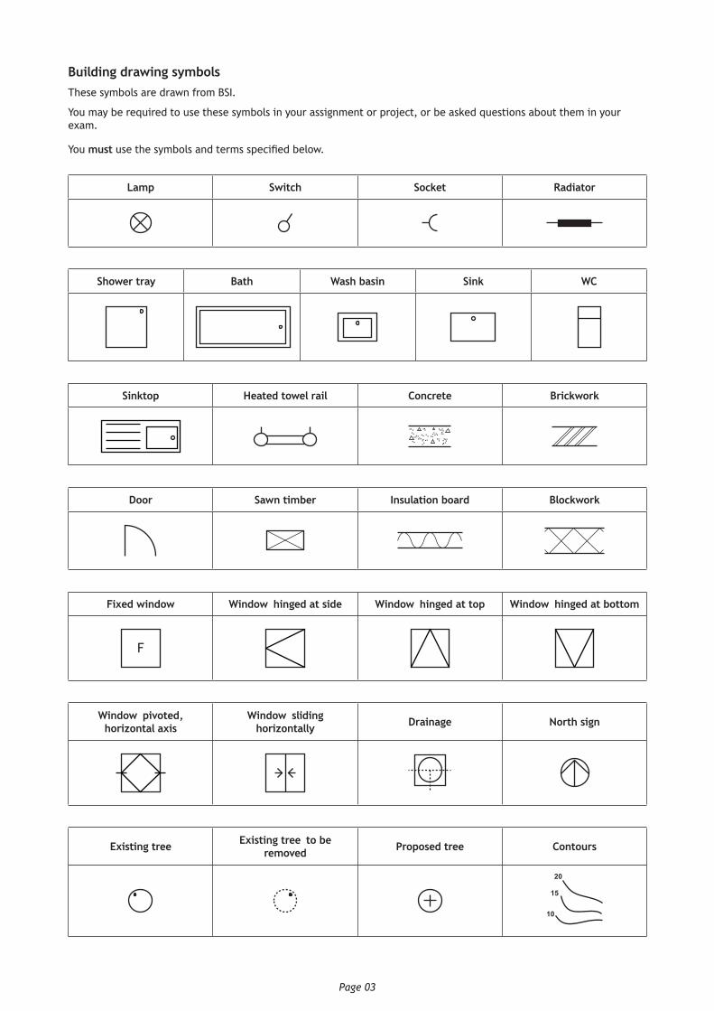
Building drawing symbolsThese symbols are drawn from BSI.
You may be required to use these symbols in your assignment or project, or be asked questions about them in your exam.
You must use the symbols and terms specified below.
Lamp Switch Socket Radiator
Shower tray Bath Wash basin Sink WC
Sinktop Heated towel rail Concrete Brickwork
Door Sawn timber Insulation board Blockwork
Fixed window Window–hinged at side Window–hinged at top Window–hinged at bottom
F
Window–pivoted, horizontal axis
Window–sliding horizontally Drainage North sign
Existing tree Existing tree–to be removed Proposed tree Contours
20
15
10

Page 04
Technical graphic line typesThese are the technical graphic line types that you should use in your work.
Outline solid Projection line Hidden detail line Centre line
Continuous thick line for visible edges and outlines.
Continuous thin line for projecting between views.
Dashed thin line for hidden detail.
Long dash, dot, chain line for centres of symmetry.
Please note that BS (7)308 (long dash, short dash chain) is also acceptable.
Fold line Cutting plane Knurling
Thin long dash, double dot, chain line to indicate folds on surface developments.
BS (7)308 (long dash, short double dash chain) is also acceptable)
A
A
Long dashed dotted thin line, thick at ends. Please note that BS (7)308 (long dash, short dash (chain) line thick at ends is also acceptable.
Springs
Page 05
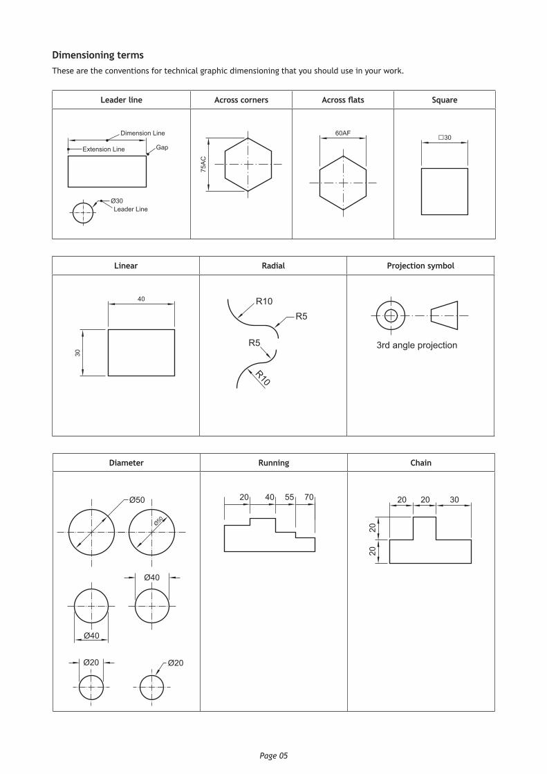
Dimensioning termsThese are the conventions for technical graphic dimensioning that you should use in your work.
Leader line Across corners Across flats Square
Dimension Line
Ø30
Extension Line
Leader Line
Gap
75A
C
60AF □30
Linear Radial Projection symbol
40
30
R10R5
R5
R10
3rd angle projection
Diameter Running Chain
Ø50
Ø20
Ø40
Ø20
Ø40
Ø50
20 40 55 70 20
2020
20 30

Page 06
Parallel Major and minor axis
20
40
70Major Axis
Min
or A
xis
Pitch circle diameter Angular dimension
Pitch Circle PCD 50 67°
Internal screw threads External screw threads
Tolerances
Common tolerance Asymmetrical tolerance
Symmetrical tolerance Functional tolerance Non-functional
tolerance
30,9530,55
+0,3530 – 0,55 30 ± 0,15
F NF
The Common method shows the upper limit of the size placed above the lower limit.
The Asymmetrical method shows the nominal size plus the upper and lower limits of the tolerance.
The Symmetrical method shows the nominal size and the symmetrical tolerance expressed as a plus and minus.
A dimension that is essential to the function of a component or space.
A dimension that is not essential to the function of a component or space.
Page 07
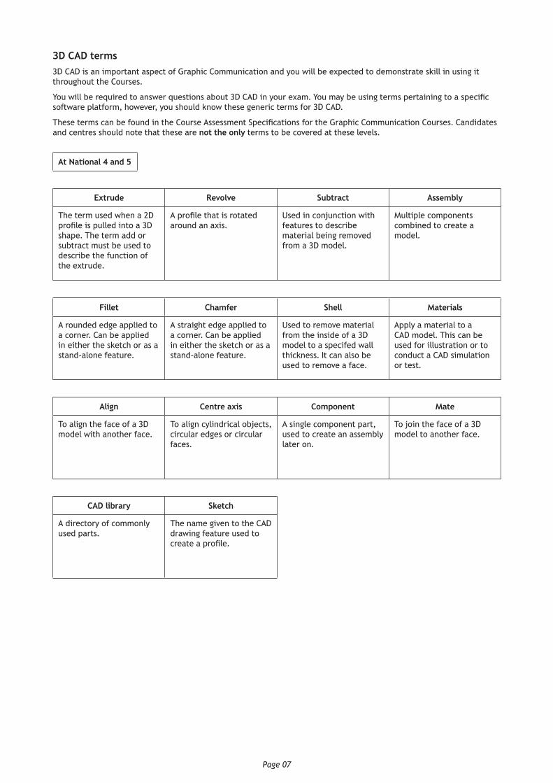
3D CAD terms3D CAD is an important aspect of Graphic Communication and you will be expected to demonstrate skill in using it throughout the Courses.
You will be required to answer questions about 3D CAD in your exam. You may be using terms pertaining to a specific software platform, however, you should know these generic terms for 3D CAD.
These terms can be found in the Course Assessment Specifications for the Graphic Communication Courses. Candidates and centres should note that these are not the only terms to be covered at these levels.
At National 4 and 5
Extrude Revolve Subtract Assembly
The term used when a 2D profile is pulled into a 3D shape. The term add or subtract must be used to describe the function of the extrude.
A profile that is rotated around an axis.
Used in conjunction with features to describe material being removed from a 3D model.
Multiple components combined to create a model.
Fillet Chamfer Shell Materials
A rounded edge applied to a corner. Can be applied in either the sketch or as a stand-alone feature.
A straight edge applied to a corner. Can be applied in either the sketch or as a stand-alone feature.
Used to remove material from the inside of a 3D model to a specifed wall thickness. It can also be used to remove a face.
Apply a material to a CAD model. This can be used for illustration or to conduct a CAD simulation or test.
Align Centre axis Component Mate
To align the face of a 3D model with another face.
To align cylindrical objects, circular edges or circular faces.
A single component part, used to create an assembly later on.
To join the face of a 3D model to another face.
CAD library Sketch
A directory of commonly used parts.
The name given to the CAD drawing feature used to create a profile.

Page 08
At Higher, in addition to those at National 4 and 5
Orientate Offset Offset – (2D CAD)
Constrains faces, straight edges, or workplanes at an angle.
Mates or aligns two faces or workplanes by making their planes parallel and constraining the separation distance between the planes.
Is used to create parallel copies of sketch objects, lines, or curves at a specified distance from the original.
Constraint Add Profile
Dimension tool used to lock 2D geometry to a particular shape, size or position.
Used in conjunction with features to describe an addition to the 3D model.
The name given to a 2D shape, prior to being used to make a 3D feature.
Radial Array Workplane Array Projected edge
An item repeated in a circle with regular spacing.
A surface where sketches can be applied. Most CAD packages will provide three (elevation, end elevation and plan), but more can be added by the user.
A method of repeating a shape along a line, in a box or round a circle.
To select an edge from a CAD model or feature and generate it as a new line in a sketch.
Fixed Vertices Edge Faces
To hold a 3D CAD model in a fixed point, without applying any constraints.
Usually applied to the first component in an assembly.
The “corners” or where edges meet on a 3D object.
The edges of a 3D object. The face of a 3D object.
Loft Irregular fillet Linear array Box array
A command where two or more profiles on workplanes that are spaced apart, are joined to create a 3D feature.
A rounding of an edge, where the radius will change.
An item repeated along an edge, with regular spacing.
An item repeated in a square or rectangle, with regular spacing.
Irregular chamfer Helix Extrude along a path Intersect
The removal of an edge by a cut, where the distance changes along the length of the edge.
A profile that revolves around an axis, but has an offset or pitch’ distance.
Often used to model threads, screws or springs.
A profile that has been extruded by following a set route or ‘path’.
Two 3D CAD features that pass through one another, with the result that only the area that the two touch remains. Everything else is deleted.
Page 09
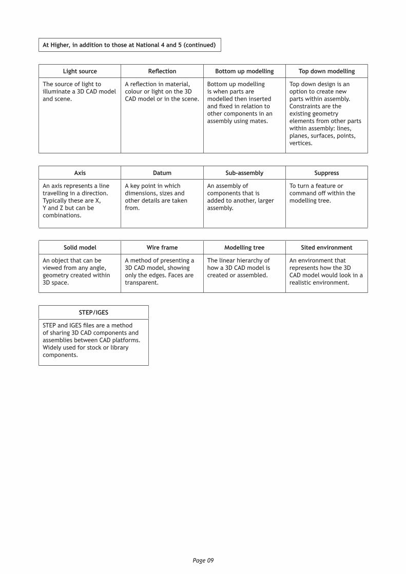
At Higher, in addition to those at National 4 and 5 (continued)
Light source Reflection Bottom up modelling Top down modelling
The source of light to illuminate a 3D CAD model and scene.
A reflection in material, colour or light on the 3D CAD model or in the scene.
Bottom up modelling is when parts are modelled then inserted and fixed in relation to other components in an assembly using mates.
Top down design is an option to create new parts within assembly. Constraints are the existing geometry elements from other parts within assembly: lines, planes, surfaces, points, vertices.
Axis Datum Sub-assembly Suppress
An axis represents a line travelling in a direction. Typically these are X, Y and Z but can be combinations.
A key point in which dimensions, sizes and other details are taken from.
An assembly of components that is added to another, larger assembly.
To turn a feature or command off within the modelling tree.
Solid model Wire frame Modelling tree Sited environment
An object that can be viewed from any angle, geometry created within 3D space.
A method of presenting a 3D CAD model, showing only the edges. Faces are transparent.
The linear hierarchy of how a 3D CAD model is created or assembled.
An environment that represents how the 3D CAD model would look in a realistic environment.
STEP/IGES
STEP and IGES files are a method of sharing 3D CAD components and assemblies between CAD platforms. Widely used for stock or library components.
Page 10
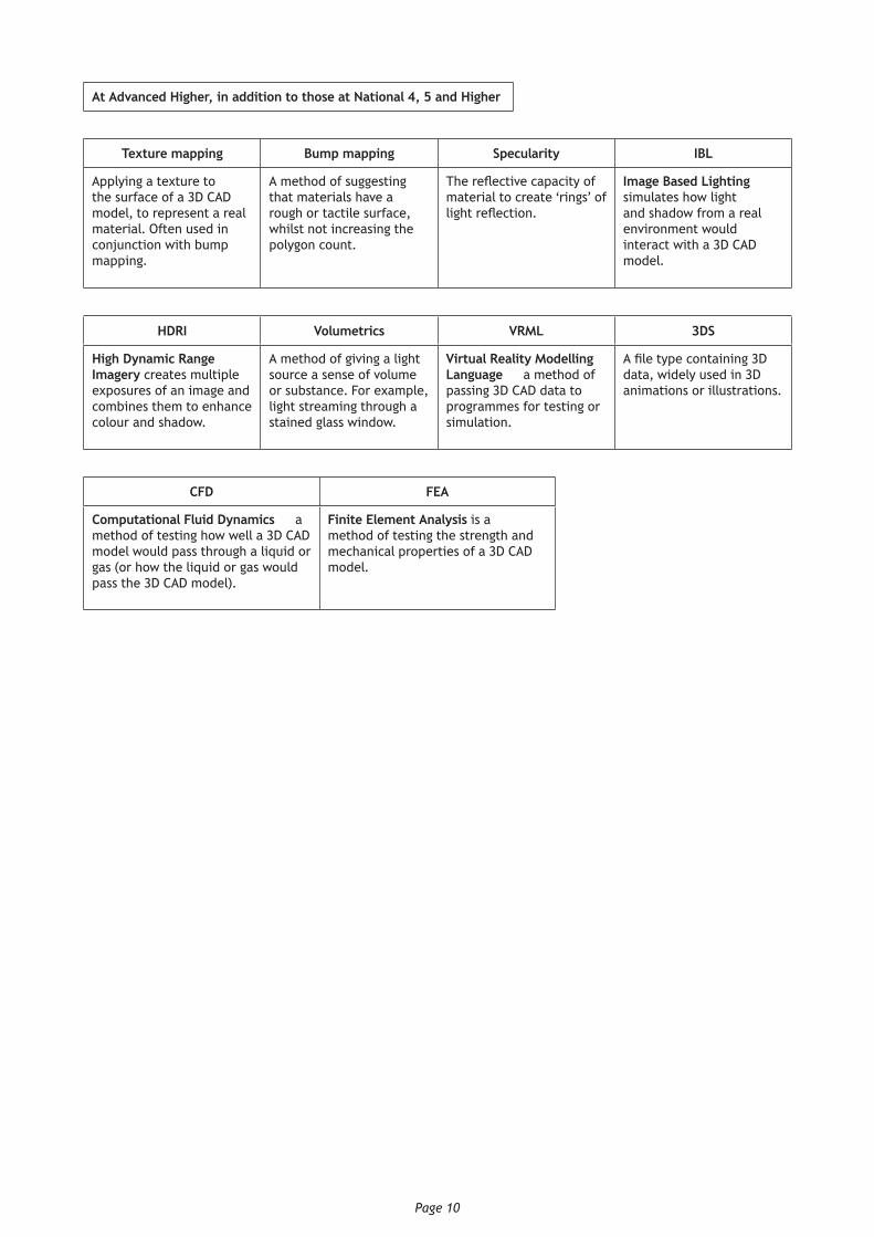
At Advanced Higher, in addition to those at National 4, 5 and Higher
Texture mapping Bump mapping Specularity IBL
Applying a texture to the surface of a 3D CAD model, to represent a real material. Often used in conjunction with bump mapping.
A method of suggesting that materials have a rough or tactile surface, whilst not increasing the polygon count.
The reflective capacity of material to create ‘rings’ of light reflection.
Image Based Lighting simulates how light and shadow from a real environment would interact with a 3D CAD model.
HDRI Volumetrics VRML 3DS
High Dynamic Range Imagery creates multiple exposures of an image and combines them to enhance colour and shadow.
A method of giving a light source a sense of volume or substance. For example, light streaming through a stained glass window.
Virtual Reality Modelling Language — a method of passing 3D CAD data to programmes for testing or simulation.
A file type containing 3D data, widely used in 3D animations or illustrations.
CFD FEA
Computational Fluid Dynamics — a method of testing how well a 3D CAD model would pass through a liquid or gas (or how the liquid or gas would pass the 3D CAD model).
Finite Element Analysis is a method of testing the strength and mechanical properties of a 3D CAD model.
Page 11
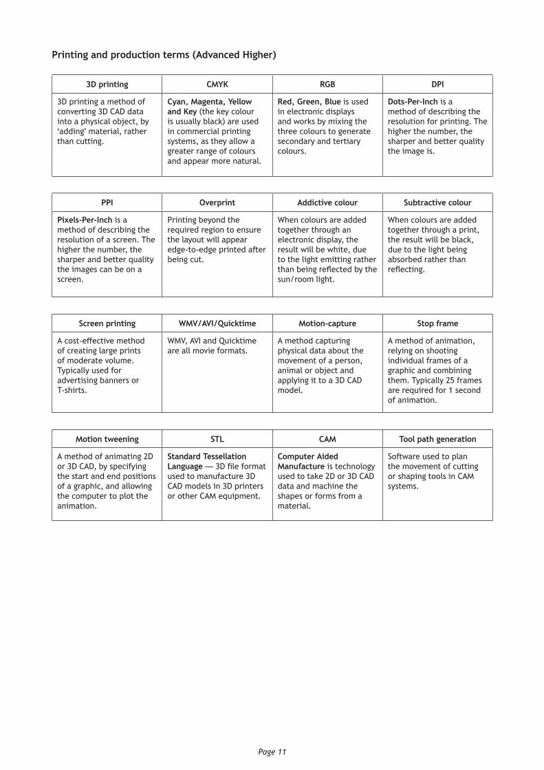
Printing and production terms (Advanced Higher)
3D printing CMYK RGB DPI
3D printing a method of converting 3D CAD data into a physical object, by ‘adding’ material, rather than cutting.
Cyan, Magenta, Yellow and Key (the key colour is usually black) are used in commercial printing systems, as they allow a greater range of colours and appear more natural.
Red, Green, Blue is used in electronic displays and works by mixing the three colours to generate secondary and tertiary colours.
Dots-Per-Inch is a method of describing the resolution for printing. The higher the number, the sharper and better quality the image is.
PPI Overprint Addictive colour Subtractive colour
Pixels-Per-Inch is a method of describing the resolution of a screen. The higher the number, the sharper and better quality the images can be on a screen.
Printing beyond the required region to ensure the layout will appear edge-to-edge printed after being cut.
When colours are added together through an electronic display, the result will be white, due to the light emitting rather than being reflected by the sun/room light.
When colours are added together through a print, the result will be black, due to the light being absorbed rather than reflecting.
Screen printing WMV/AVI/Quicktime Motion-capture Stop frame
A cost-effective method of creating large prints of moderate volume. Typically used for advertising banners or T-shirts.
WMV, AVI and Quicktime are all movie formats.
A method capturing physical data about the movement of a person, animal or object and applying it to a 3D CAD model.
A method of animation, relying on shooting individual frames of a graphic and combining them. Typically 25 frames are required for 1 second of animation.
Motion tweening STL CAM Tool path generation
A method of animating 2D or 3D CAD, by specifying the start and end positions of a graphic, and allowing the computer to plot the animation.
Standard Tessellation Language — 3D file format used to manufacture 3D CAD models in 3D printers or other CAM equipment.
Computer Aided Manufacture is technology used to take 2D or 3D CAD data and machine the shapes or forms from a material.
Software used to plan the movement of cutting or shaping tools in CAM systems.

Published: August 2016
Change since last published:Minor corrections to fix errors