GRAIN CART RETROFIT KINZE 1050 / 900 ... - Cloud Storage · GRAIN CART RETROFIT KINZE 1050 / 900 /...
11
7600240 REVA ©Scale-Tec 2014 GRAIN CART RETROFIT KINZE 1050 / 900 / 1100 / 1300 / 1500 Instructions This manual is copyrighted by Scale-Tec. Redistribution or copy of this manual or portions of this manual must be approved through Scale-Tec and are strictly prohibited.
Transcript of GRAIN CART RETROFIT KINZE 1050 / 900 ... - Cloud Storage · GRAIN CART RETROFIT KINZE 1050 / 900 /...

7600240 REVA ©Scale-Tec 2014
GRAIN CART RETROFIT
KINZE 1050 / 900 / 1100 / 1300 / 1500
Instructions
This manual is copyrighted by Scale-Tec.
Redistribution or copy of this manual or portions of this manual must be approved through Scale-Tec and are strictly prohibited.

TABLE OF CONTENTS
7600240 REVA ©Scale-Tec 2014
Page 2
Anamosa, Iowa USA
TABLE OF CONTENTS
INTRODUCTION ............................................................................................................................................. 3
Charging Battery and Welding .................................................................................................................. 3
SCALE BRACKET AND LOAD CELL MOUNTING INSTALLATION ...................................................................... 4
Scale Installation ....................................................................................................................................... 4
JUNCTION BOX MOUNTING .......................................................................................................................... 9
Four Hole Junction Box ............................................................................................................................. 9
INDICATOR MOUNTING .............................................................................................................................. 10
RAM MOUNT........................................................................................................................................... 10
TESTING AND TROUBLE SHOOTING ............................................................................................................ 11
Inaccurate weights? ................................................................................................................................ 11
Erratic weights?....................................................................................................................................... 11
INTRODUCTION
7600240 REVA ©Scale-Tec 2014
Page 3
INTRODUCTION Congratulations on the purchase of your new Scale-Tec Grain Cart scale system. This scale system is specifically designed to weigh the hopper on your Grain Cart. This scale kit is specifically designed for your make and model of Grain Cart. These instructions will guide you through general installation of the kit. The scale kit can be used to record and monitor seed weight going into or out of the grain cart.
This SAFETY ALERT SYMBOL indicates important safety messages in the manual. When you see this symbol, be alert to the possibility of PERSONAL INJURY and carefully read the message that follows.
NEVER OPERATE WITHOUT ALL COVERS, SHIELDS AND GUARDS IN PLACE. KEEPHANDS, FEET AND CLOTHING AWAY FROM MOVING PARTS. FAILURE TO HEED MAY RESULT INSERIOUS PERSONAL INJURY OR DEATH. Some covers and guards have been removed for illustrative/photographic purposes only in this manual.
For information on ordering repair parts, refer to Parts Section in this book.
This supersedes all previous published instructions.
IMPORTANT!
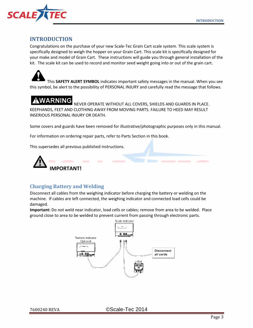
Charging Battery and Welding Disconnect all cables from the weighing indicator before charging the battery or welding on the machine. If cables are left connected, the weighing indicator and connected load cells could be damaged. Important: Do not weld near indicator, load cells or cables; remove from area to be welded. Place ground close to area to be welded to prevent current from passing through electronic parts.

SCALE INSTALLATION
7600240 REVA ©Scale-Tec 2014
Page 4
SCALE BRACKET AND LOAD CELL MOUNTING INSTALLATION
Scale Installation The scale kit consists of mounting two Compression load cells, one hitch load cell, one J-box and a scale
indicator to support the seed hopper.
1. Remove existing hitch as required.
IMPORTANT! Ensure you block and brace the hitch
area while removing the hitch. Jack failure can cause
serious or deadly injury.
Fig. 1
Fig. 2
Refer to Fig. 1.
i. Remove the Existing Hitch from the grain cart.
ii. Depending on features ordered with grain cart, your Kinze 1050 Grain Cart may have a fixed rigid hitch, or a swivel hitch. Both types of hitches including the swivel hitch must be removed from the cart, including the end cap.
iii. If your grain cart has a swivel hitch,
you must keep your receiver and reuse the receiver for the load cell installation.
Refer to Figure 2
i. Install the new end cap utilizing the existing hardware.
ii. Install the load cell into the new end cap sleeve. (Arrow Pointed UP)
iii. Install the receiver onto the end of the load cell.
IMPORTANT! For Digi-Star load cells ensure the arrow sticker is pointed “UP”. For weigh-Tronix weigh bars, ensure the “TOP” sticker is positioned on top.

SCALE INSTALLATION
7600240 REVA ©Scale-Tec 2014
Page 5
1. Utilizing a 20 Ton Jack, raise the rear of the Grain Cart enough to take pressure off of the two rear
axle retaining pins (ensure you block the rear of the grain cart for safety, Jack failure can cause injury
and loss of life)
SAFETY!!! Ensure you properly block the Grain Cart to provide support in the event of a jack
failure or lifting device failure.
2. Remove the two rear horizontal Pins
Fig. 3
Fig. 4
Refer to Fig. 3 To remove horizontal pins…
i. Remove the retaining bolt on the outside of the cart frame.
ii. Remove the inside retaining bolts and four spacer washers.
iii. With pressure completely removed from the horizontal pin, remove it from the cart. Keep the pin a clean environment, it will be neccessary to reinstall the pin once the loadcells have been installed.
Refer to Fig. 4
i. After removing the rear horizontal hinge pins, raise the hopper enough clearance to remove the steel vertical pins. Refer to the arrow on figure 4 for the location of the steel vertical pin.
IMPORTANT! Prior to removing the small vertical pins, ensure you have braced the cart. This is a very vulnerable area and in the event of a jack failure, loss of limb injury can be possible.

SCALE INSTALLATION
7600240 REVA ©Scale-Tec 2014
Page 6
3. Install the rear compression load cells.
Fig. 5
Refer to Fig. 5
i. Loosely install the bottom load cell retaining plate on the Grain Cart. Figure 5 shows the expanded assembly of the load cell retainer.
ii. Install the load cell into the retainer plate. Ensure that the load cell is not suspended by the retainer plate. When installed properly, the load cell should bottom out and make contact with the undercarriage of the Grain Cart.
iii. Tighten the load cell retainer hardware.
IMPORTANT! Ensure the notched end of the load cell fits into the retainer plate. This will prevent the load cell from turning.

SCALE INSTALLATION
7600240 REVA ©Scale-Tec 2014
Page 7
Fig. 6
Fig. 7
Fig. 8
Refer to Fig. 6
i. Slowly lower the hopper, ensuring the load cell fits inside the top gusset ring of the frame. The load cell should be perpendicular to the frame of the cart, if it is not adjust load cell for proper orientation.
ii. IMPORTANT! Ensure the load cell is straight and perpendicular to the frame of the cart prior to lowering and retaining weight on the load cell. If the load cell is not perpendicular to the cart damage may occur to the load cell.
Refer to Fig. 7
iii. Re-install the rear horizontal hinge pin on the grain cart.
Refer to Fig 8 iv. Install three of the four washers on the
horizontal hinge pin. Do not utilize all four washers. This will cause binding and inaccurate loads with the scale system.
v. Grease the horizontal hinge pin.

SCALE INSTALLATION
7600240 REVA ©Scale-Tec 2014
Page 8
4. Route cabling to forward portion of the grain cart into the junction box. 5. Mount Junction box in a clean, dry location, preferably in an area free of moisture and hydraulic oil. Refer to Junction Box mounting section for proper installation.
IMPORTANT! Due to the Kinze Manufacturing process and the welding procedures during the manufacture of the Grain Cart, it may be necessary to “shim” the load cells in order to register an accurate weight on the scale system. Every Kinze Grain Cart is “unique” in this manner and it has been found that various Kinze Grain Carts will need this shim. Scale-Tec has shims available in the event your Grain Cart does not weigh accurately after installation has been performed. While this has not been the case of all Kinze Grain Carts it has been found to be the solution to inaccurate weight readings on the Kinze 900, 1050, 1100, 1300, 1500 and the design of the Grain Cart. Contact Scale-Tec (888) 962-2344 for further questions regarding this matter.

JUNCTION BOX MOUNTING
7600240 REVA ©Scale-Tec 2014
Page 9
JUNCTION BOX MOUNTING
Four Hole Junction Box The junction box is water resistant, not water-proof. It should be mounted to avoid submersion during
wetweather and to avoid physical abuse. The junction box can be mounted on the frame of the grain
cart. All load cell cables must reach the J-Box. Install by removing the double sided tapebacking and
apply to cleaned surface.
Connect Load Cell and Indicator “J-Box” Cable 1. Route front and rear load cell cables to J-box location. Make sure they are not bound or pinched. Cable tie
(customer provided) load cell cables in place.
2. Insert load cell and J-box cables through each of the
water-tight strain-reliefs.
3. Remove each terminal block from the J-box.
4. Connect wires of the same color to the same terminal
block as shown above. See instructions below.
5. Install terminal block into the J-box as shown (location
not important).
6. Tighten nuts on the water-tight strain-reliefs.
7. Assure that gasket is properly installed in the cover.
8. Attach cover using 4 screws (provided).
Installing Wires into Terminal Block 1. Open levers 90º to locked position.
2. Insert individual wires into terminal.
3. Close lever.
4. Tug wire to assure solid connection.
INDICATOR MOUNTING
7600240 REVA ©Scale-Tec 2014
Page 10
INDICATOR MOUNTING
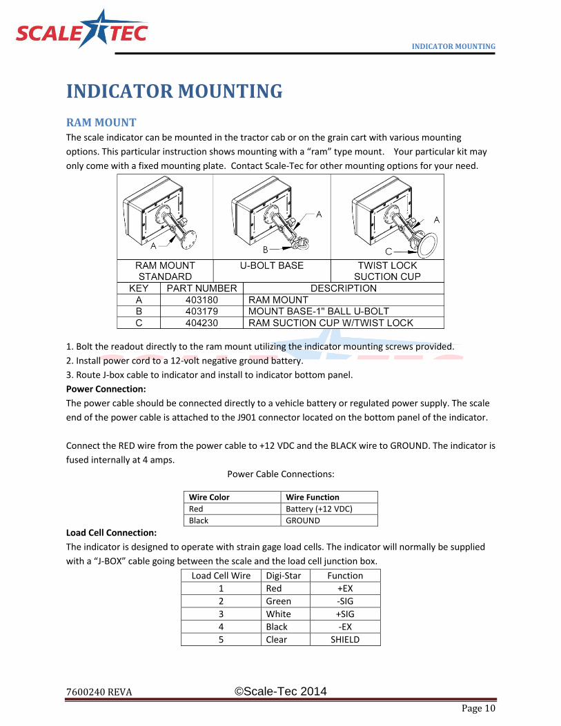
RAM MOUNT The scale indicator can be mounted in the tractor cab or on the grain cart with various mounting
options. This particular instruction shows mounting with a “ram” type mount. Your particular kit may
only come with a fixed mounting plate. Contact Scale-Tec for other mounting options for your need.
1. Bolt the readout directly to the ram mount utilizing the indicator mounting screws provided.
2. Install power cord to a 12-volt negative ground battery.
3. Route J-box cable to indicator and install to indicator bottom panel.
Power Connection:
The power cable should be connected directly to a vehicle battery or regulated power supply. The scale
end of the power cable is attached to the J901 connector located on the bottom panel of the indicator.
Connect the RED wire from the power cable to +12 VDC and the BLACK wire to GROUND. The indicator is
fused internally at 4 amps.
Power Cable Connections:
Wire Color Wire Function
Red Battery (+12 VDC)
Black GROUND
Load Cell Connection:
The indicator is designed to operate with strain gage load cells. The indicator will normally be supplied
with a “J-BOX” cable going between the scale and the load cell junction box.
Load Cell Wire Digi-Star Function
1 Red +EX
2 Green -SIG
3 White +SIG
4 Black -EX
5 Clear SHIELD

TESTING AND TROUBLE SHOOTING
7600240 REVA ©Scale-Tec 2014
Page 11
TESTING AND TROUBLE SHOOTING
IMPROTANT All bars need to weigh accurately before it will be beneficial to recalibrate your
indicator
Inaccurate weights? 1) Measure the same person, or a 200 pound bag of seed, on each of the weigh bars.
If one weighs negative, turn that weigh bar over. (An upside down bar will weigh negative.)
If one side is weighing 20% light, check for an obstruction. Is anything binding or any metal
rubbing?
Could be a faulty weigh bar
If they are all even weights, but are weighing light or heavy, you need to adjust the calibration.
If your scale is more than 5% off, call us for help, as your scale may have had the wrong
calibration number put in it from the factory. 1-888-962-2344.
The hopper being weighed needs to be at least ¾ full for us to adjust calibration.
Check operator’s manual or give us a call at 1-888-962-2344.
Erratic weights? The following process needs to occur in an effort to eliminate one part at a time in an effort to find the
problem! When you reconnect the faulty part you will have erratic readings again.
1) Disconnect the junction box cord from the indicator marked “load cells”. The indicator should
stabilize after 45 seconds. Try to zero out the indicator. IF the indicator won’t zero out, the indicator is
the problem.
IF it will zero out:
2) Connect the junction box back to the indicator. And then disconnect all of the load cells from the
junction box.
3) Zero out the indicator. IF the indicator won’t zero out the problem is the junction box or the junction
box cable.
IF it will zero out:
4) Reconnect the load cells ONE AT A TIME, zeroing out the indicator each time. When you reconnect
the faulty load cell, you will have erratic readings again.