GRAIL: GNSS Introduction in the RAIL sector GRAIL-WP3-TIF-DEL-3.1.1 Issue: 1.0 Date: 25/06/07 GNSS...
52
Project funded by the European GNSS Supervisory Authority 6FP 2 nd Call. Area 1A: User Segment, User Community Contract: GJU/05/2409/CTR/GRAIL GRAIL: GNSS Introduction in the RAIL sector GNSS Subsystem Requirements Specification for Enhanced Odometry Application Issue 1.0 Date 25/06/07 Number of pages 48 Classification PUB Document Reference Project Work package Partner Nature Number GRAIL WP3.1 TIFSA DEL 3.1.1 Partner reference (optional) Responsible Name/Company Signature Date Author AAS-I/ANS/ SIE/ TIF 30/03/07 WP Leader Mª José García /TIFSA 30/03/07 Project coordinator A Urech/INECO 30/03/07 GSA Project Officer Stefano Scarda 22/05/07
Transcript of GRAIL: GNSS Introduction in the RAIL sector GRAIL-WP3-TIF-DEL-3.1.1 Issue: 1.0 Date: 25/06/07 GNSS...

Project funded by the European GNSS Supervisory Authority 6FP 2nd Call. Area 1A: User Segment, User Community
Contract: GJU/05/2409/CTR/GRAIL
GRAIL: GNSS Introduction in the RAIL sector
GNSS Subsystem Requirements Specification for Enhanced Odometry
Application Issue 1.0 Date 25/06/07
Number of pages 48 Classification PUB
Document Reference
Project Work package Partner Nature Number
GRAIL WP3.1 TIFSA DEL 3.1.1
Partner reference (optional)
Responsible Name/Company Signature Date
Author AAS-I/ANS/ SIE/ TIF 30/03/07
WP Leader Mª José García /TIFSA 30/03/07
Project coordinator A Urech/INECO 30/03/07
GSA Project Officer Stefano Scarda 22/05/07

Ref: GRAIL-WP3-TIF-DEL-3.1.1
Issue: 1.0 Date: 25/06/07
GNSS Subsystem Requirement Specification for Enhanced Odometry
Application Class: PUB Page 2 / 48
GRAIL: GNSS Introduction in the RAIL sector GSA Contract Number: GJU/05/2409/CTR/GRAIL
DOCUMENT CHANGE LOG
Issue Date Affected Sections Comments
0.1 12/04/2006 All Functional description - 1st Draft
0.2 12/05/2006 1.4, 1.5, 2, 3 comments from AAS included comments from SIEMENS included comments from ALCATEL included ANSALDO proposal for section 3 included
0.3 23/06/2006 Section 1, 2 and 3 Comments from BOMBARDIER, SIEMENS, ALSTOM and DIMETRONIC Corrections after progress and technical meeting (Madrid, 30th May 2006)
0.4 06/07/06 Section 1.5, 2, 3 and 4
Comments from ALSTOM SIEMENS contribution added
0.5 14/08/06 Section 1.5 and 3 Corrections after progress and technical meeting (Madrid, 13th July 2006)
0.6 29/09/2006 Section 2 and 3 Comments from BOMBARDIER and corrections after progress and technical meeting (Berlin, 30th and 31st August 2006) AAS-I contribution added (section 3.3)
0.7 10/11/2006 Section 3.3.1 Comments from ALSTOM, ALCATEL, BOMBARDIER and SIEMENS implemented according to agreement of 7/11/2006 Madrid meeting
0.8 17/11/2006 All Comments from AASI, CED and ANS Corrections after progress and technical meeting (Madrid, 07th November 2006)
0.9 01/12/2006 All Revision for first official delivery
0.a 10/12/2006 All Review by Coordinator
0.b 30/03/2007 All Review after comments from external reviewer SPMJ Typo review after comments from ALCATEL, ALSTOM and SIE
1.0 25/06/07 All First Approved version.

Ref: GRAIL-WP3-TIF-DEL-3.1.1
Issue: 1.0 Date: 25/06/07
GNSS Subsystem Requirement Specification for Enhanced Odometry
Application Class: PUB Page 3 / 48
GRAIL: GNSS Introduction in the RAIL sector GSA Contract Number: GJU/05/2409/CTR/GRAIL
DOCUMENT DISTRIBUTION
To/cc Organisation Name
To GSA Stefano Scarda
To INECO Alvaro Urech
To TIFSA Mª José García
To ANSALDO-CSEE Celso Prados
To ALSTOM Michel Rousseau
To SIEMENS Klaus Jaschke
To DIMETRONIC Beatriz Muñoz
To THALES Karl Brocke
To BOMBARDIER Georg Mandelka
To THALES ALENIA SPACE Livio Marradi
To CEDEX Daniel Molina
To RSSB Martyn Thomas
To DLR Michael Meyer zu Hoerste
Cc ADIF Javier Vicente
Cc Deimos Space Antonio Fernández
Cc ESSP Umberto Guida
Cc ESYS Bryan Jenkins
Cc IIASL Frans von der Dunk
Cc Indra Espacio Carlos Álvarez
Cc NSL William Roberts

Ref: GRAIL-WP3-TIF-DEL-3.1.1
Issue: 1.0 Date: 25/06/07
GNSS Subsystem Requirement Specification for Enhanced Odometry
Application Class: PUB Page 4 / 48
GRAIL: GNSS Introduction in the RAIL sector GSA Contract Number: GJU/05/2409/CTR/GRAIL
TABLE OF CONTENTS
1 INTRODUCTION.................................................................................................6 1.1 Purpose.................................................................................................................................. 6 1.2 Intended audience / Classification ......................................................................................... 6 1.3 Reference documentation ...................................................................................................... 6 1.4 Associated documentation ..................................................................................................... 6 1.5 Abbreviations and Acronyms ................................................................................................. 6 1.6 Glossary of Terms and Definitions ......................................................................................... 8
2 INTEGRATION OF GNSS INTO CURRENT ETCS ODOMETRY....................14
3 GNSS ENHANCED ODOMETRY SUBSYSTEM REQUIREMENTS SPECIFICATIONS...................................................................................................16 3.1 Functional description .......................................................................................................... 16
3.1.1 GNSS Enhanced Odometry Subsystem ....................................................................... 16 3.1.2 Requirements of performance for odometry macrofunction.......................................... 18
3.2 Architecture .......................................................................................................................... 19 3.3 Requirements for the on–board and trackside modules. Allocation of functions. ................ 20
3.3.1 General requirements for the GNSS Enhanced Odometry Subsystem ........................ 20 3.3.2 Specification for the User Terminal ............................................................................... 21 3.3.3 Specification for the local augmentation ....................................................................... 47
3.4 Interfaces ............................................................................................................................. 47 3.4.1 Definition of internal interfaces...................................................................................... 47 3.4.2 Identification of external interfaces ............................................................................... 47
4 IMPACT ON ETCS SYSTEM REQUIREMENTS SPECIFICATION .................48
APPENDICES:
APPENDIX A: GNSS ACCURACY
APPENDIX B: GNSS ENHANCED ODOMETRYY ARCHITECTURE APPROACHES

Ref: GRAIL-WP3-TIF-DEL-3.1.1
Issue: 1.0 Date: 25/06/07
GNSS Subsystem Requirement Specification for Enhanced Odometry
Application Class: PUB Page 5 / 48
GRAIL: GNSS Introduction in the RAIL sector GSA Contract Number: GJU/05/2409/CTR/GRAIL
LIST OF FIGURES
Figure 1: GNSS Enhanced Odometry Subsystem external interfaces ........................................... 10 Figure 2: User Terminal .................................................................................................................. 13 Figure 3: Data flow between GNSS Enhanced Odometry Subsystem and ETCS on board........... 18 Figure 4: Selected approach........................................................................................................... 20 Figure 5: The travelled distance parameters .................................................................................. 27

Ref: GRAIL-WP3-TIF-DEL-3.1.1
Issue: 1.0 Date: 25/06/07
GNSS Subsystem Requirement Specification for Enhanced Odometry
Application Class: PUB Page 6 / 48
GRAIL: GNSS Introduction in the RAIL sector GSA Contract Number: GJU/05/2409/CTR/GRAIL
1 INTRODUCTION
1.1 Purpose
The purpose of this document is to provide an initial definition of a GNSS-based subsystem to be used for Enhanced Odometry.
This document contains the functional description, the system architecture and the requirements for the new on-board and trackside parts.
This document corresponds to a WP3 deliverable document as planned in the Work Plan and in the Technical Annex of the Contract. An updated version of this document will be prepared near the end of the project including the feedback from the field trials and stakeholder consultation.
1.2 Intended audience / Classification
This document is public. It may be distributed freely, both within and outside the project.
1.3 Reference documentation
[1] GRAIL Contract: GJU/05/2409/CTR/GRAIL
[2] GRAIL Consortium Agreement
[3] Project Management Plan (GRAIL-WP0-INE-DEL-01) Issue 0.2
[4] Project Handbook (GRAIL-WP0-INE-DEL-02) Issue 0.2
[5] ERTMS/ETCS - SSRS - Subset 030 System macro functions overview
[6] ERTMS/ETCS - SSRS - Subset 031 On-board subsystem requirement specification
1.4 Associated documentation
[7] ERTMS/ETCS - FRS version 4_29
[8] ERTMS/ETCS – SRS – Subset 026, v2.2.2 - System Requirement Specification
[9] ERTMS/ETCS –Subset 036 Version 2.3.0 FFFIS for Eurobalise
[10] GIRA-WP2-AAS-DEL-21, Issue 10, GIRASOLE Receiver Specification for Railway Applications
[11] GADEROS-TIF-WP2-DEL-10, On-board Location Subsystem Requirements Specifications
[12] GADEROS-TIF-WP2-DEL-20, Interface Control Document
[13] ERTMS/ETCS Subset-041, version 2.1.0 –Performance a requirements for interoperability
[14] ERTMS/ETCS Subset-035 version 2.1.1– Specific Transmission Module FFFIS
[15] GRAIL-WP3-ANS-DEL-3.2.1, v0.4 – Interface Specification for Enhanced Odometry
1.5 Abbreviations and Acronyms
ATP Automatic Train Protection
BPSK Binary Phase Shift Keying

Ref: GRAIL-WP3-TIF-DEL-3.1.1
Issue: 1.0 Date: 25/06/07
GNSS Subsystem Requirement Specification for Enhanced Odometry
Application Class: PUB Page 7 / 48
GRAIL: GNSS Introduction in the RAIL sector GSA Contract Number: GJU/05/2409/CTR/GRAIL
BTM Balise Transmission Module
CTODL Current Time Odometric Data Line
D_LRBG Distance between the last relevant balise group and the estimated front end of the train of the active cab
DOP Dilution of Precision
E5 Galileo Frequency Band
EPE Estimated Position Error
ERTMS European Railway Traffic Management System
ETCS European Train Control System
EVC European Vital Computer
FFFIS Form Functional Fit Interface Specification
FIS Functional Interface Specification
FFFIS Form Fit Functional Interface Specification
FRS Functional Requirement Specification
GJU Galileo Joint Undertaking
GNSS Global Navigation Satellite System
GPS Global Positioning System
IMU Inertial Measurement Unit
INS Inertial Navigation System
K Confidence Interval
L11 GPS Frequency Band
L22 GPS Frequency Band
LE Local Elements
LRBG Last Relevant Balise Group
LU Location Unit
NID_BG Identity number of the balise group
Q_LINKACC Accuracy of the balise location
PVHT Position, Velocity, Heading, Time
PVT Position, Velocity, Time
RAMS Reliability, Availability, Maintainability, Safety
Rx Receiver
SIL Safety Integrity Level
SIS Signal in Space
1 In ERTMS context L1 means “ERTMS Level 1” 2 In ERTMS context L2 means “ERTMS Level 2”
Ref: GRAIL-WP3-TIF-DEL-3.1.1
Issue: 1.0 Date: 25/06/07
GNSS Subsystem Requirement Specification for Enhanced Odometry
Application Class: PUB Page 8 / 48
GRAIL: GNSS Introduction in the RAIL sector GSA Contract Number: GJU/05/2409/CTR/GRAIL
SoW Statement of Work
SOL Safety of Life
SPS Standard Positioning Service
SRS System Requirement Specification
SQ Safety Qualifier
TBC To Be Confirmed
TBD To Be Defined
UNISIG Union of Signalling Industries
UT User Terminal
UTC Coordinated Universal Time
UEE User Equipment Errors
UERE User Equivalent Range Error
UERRE User equivalent Range Rate Error
WAAS Wide Area Augmentation System
WGS84 World Geodetic System 1984
WP Work Package
WPL Work Package Leader
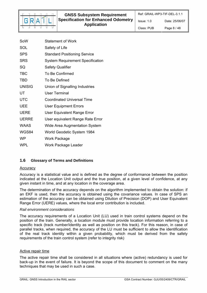
1.6 Glossary of Terms and Definitions
Accuracy
Accuracy is a statistical value and is defined as the degree of conformance between the position indicated at the Location Unit output and the true position, at a given level of confidence, at any given instant in time, and at any location in the coverage area.
The determination of the accuracy depends on the algorithm implemented to obtain the solution: if an EKF is used, then the accuracy is obtained using the covariance values. In case of SPS an estimation of the accuracy can be obtained using Dilution of Precision (DOP) and User Equivalent Range Error (UERE) values, where the local error contribution is included.
Rail environment considerations
The accuracy requirements of a Location Unit (LU) used in train control systems depend on the position of the train. Generally, a location module must provide location information referring to a specific track (track number/identity as well as position on this track). For this reason, in case of parallel tracks, when required, the accuracy of the LU must be sufficient to allow the identification of the real track identity within a given probability, which must be derived from the safety requirements of the train control system (refer to integrity risk)
Active repair time
The active repair time shall be considered in all situations where (active) redundancy is used for back-up in the event of failure. It is beyond the scope of this document to comment on the many techniques that may be used in such a case.

Ref: GRAIL-WP3-TIF-DEL-3.1.1
Issue: 1.0 Date: 25/06/07
GNSS Subsystem Requirement Specification for Enhanced Odometry
Application Class: PUB Page 9 / 48
GRAIL: GNSS Introduction in the RAIL sector GSA Contract Number: GJU/05/2409/CTR/GRAIL
The ERTMS RAMS (Reliability, Availability, Maintainability and Safety) specification may indirectly lead to identification of such a time when specifying the maximum time for recognition of a component failure (5 s). It can be expected that any active repair duration shall be in the same range (max 5 s).
Any case, usage of Galileo-Safety of Life (SoL) spare parts (active redundancy) is directly the consequence of availability requirements. Because of costs it should be avoided. The main availability gap will be caused by signal loss.
Alarm
If requested by the specific functional requirements, the Location Unit shall output the alarm information if:
• information is not ready within the rate interval;
• information is not to be trusted (cause may be reported as option).
Availability
Availability is defined as the intrinsic availability of location information fulfilling its performance requirements at the Location Unit output.
Rail environment considerations
In the current circumstances when the relative unavailability of Signal in Space (SIS) owing to limited visibility shall be accepted as a natural condition for designing a Location Unit with a highly-available positioning output at all locations - so for highly-demanding applications, lack of SIS shall not be a cause of non-availability.
In this case, the only usable standard definition for availability is the intrinsic availability.
The intrinsic availability is the "Probability that a system or equipment is operating satisfactorily at any point in time when used under stated conditions, where the time considered is operating time and active repair time. Preventive maintenance administrative and logistic times are excluded" (MIL - HDBK-388-1A).
The availability of the LU used in train control applications mainly influences the operational conception and the line performance parameters. For transport and infrastructure operators the operational availability (e.g. delay minutes) is important, which depends on the technical availability of the LU and the operational concept. Besides there is also an effect to safety because unavailability causes the use of fault back modes which are not as safe as the normal operation and therefore the “average” safety of the system decreases.
Confidence interval: TBD
Continuity
The continuity of the location information is defined as the probability that the location unit will be able to determine its position within the specified accuracy and is able to monitor the integrity of the determined position over the mission time, in all points of the route within the coverage area.

Ref: GRAIL-WP3-TIF-DEL-3.1.1
Issue: 1.0 Date: 25/06/07
GNSS Subsystem Requirement Specification for Enhanced Odometry
Application Class: PUB Page 10 / 48
GRAIL: GNSS Introduction in the RAIL sector GSA Contract Number: GJU/05/2409/CTR/GRAIL
Coverage
The coverage is defined as the surface area or volume of space where the SIS service is sufficient to permit the user to determine its position with the specified accuracy and to monitor integrity of the determined position.
It should be observed that for a Location Unit using a combination of techniques, the coverage may not have the same significance. Depending on the techniques combined, it may appear the case that some lines (areas) are not covered by ONE SPECIFIC TYPE of Location Unit, e.g. when implementing map matching techniques for improving accuracy the map can only be valid for a specific line (area). Then, it can be a requirement that some specific applications will ask for the Location Unit coverage although the SIS coverage is the ELM (European Land Mass).
Enhanced ETCS Odometry: provides processed speed and distance data provided by the fusion of GNSS User Terminal, tachometer and other sensor information. It also includes reset position and synchronization between the ETCS kernel, the BTM, etc, according to the definition made in subset 031 [6].
Fix Rate
The fix rate is the number of position fixes and the associated integrity checks per unit time. The fix rate is a property of the Location Unit.
GNSS Enhanced Odometry Subsystem
The GNSS Enhanced Odometry subsystem is composed of all new elements trackside and trainborne (GNSS technology based or not) that are needed for a particular application in ETCS involving GNSS: digital map, specific local elements, user terminal, etc., and whose interfaces are ETCS and GNSS SIS. The definition is supported by the following diagram:
GNSS subsystem ETCSSIS
Figure 1: GNSS Enhanced Odometry Subsystem external interfaces
GNSS Receiver
Is the element that has an input from the SIS and an output Position (x, y, z), Velocity, Heading, Time and integrity information.

Ref: GRAIL-WP3-TIF-DEL-3.1.1
Issue: 1.0 Date: 25/06/07
GNSS Subsystem Requirement Specification for Enhanced Odometry
Application Class: PUB Page 11 / 48
GRAIL: GNSS Introduction in the RAIL sector GSA Contract Number: GJU/05/2409/CTR/GRAIL
Integrity
Integrity relates to the trust that can be placed in the correctness of the information supplied by the Location Unit to the application. Integrity is described by three parameters:
• Threshold value or alert limit - the maximum allowable error in the measured position before an alarm is triggered.
• Time-to-alarm - the maximum allowable time between an alarm condition occurring and the alarm being present at the output.
• Integrity risk, that appears when location is out of tolerance limits (false), but the Location Unit reports "information available" and no "alarm" is triggered within the time to alarm. A Safety Integrity Level (SIL) will be assigned by WP3.4.
Rail environment considerations
The integrity risk of the GNSS UT is strongly dependent on implementation. GNSS System and GNSS Rx are only two of the components whose integrity risk contributes to the Global UT integrity risk value.
For safety relevant railway applications the integrity risk can be described by the tolerable hazard rate, which is derived from a risk analysis of the application. A safety integrity level shall be then allocated to the UT according to the application.
Local Element User Terminal (LE UT): TBD
Maintainability
Maintainability performance requirements influence:
• the maintenance and repair policy associated with the GNSS sub-system;
• the GNSS Enhanced Odometry Subsystem availability requirements.
The current most severe requirements are derived from the ETCS Functional Requirement Specification [[7] [7]RD22]:
• Maximum time to detect a module failure: 5 seconds
• Maximum time to replace the module: 5 minutes
• Maximum time to restart the system: 15 seconds
• Maximum additional time to substitute a traction unit after a failure requiring maintenance in a workshop: 3 hours.
These specific parameters may all be gathered together into a single parameter known as the service interruption threshold, which is the maximum acceptable duration for any unintended or intended interruption of service. The only part of the GNSS Enhanced Odometry Subsystem that affects local maintenance policy is the Location Unit that contains the GNSS receiver, which is the only element that is train-borne.
For safety related applications the service interrupt threshold shall be no longer than the requirement for detection of the Location Unit module failure.
Odometry function: provides processed speed and distance data

Ref: GRAIL-WP3-TIF-DEL-3.1.1
Issue: 1.0 Date: 25/06/07
GNSS Subsystem Requirement Specification for Enhanced Odometry
Application Class: PUB Page 12 / 48
GRAIL: GNSS Introduction in the RAIL sector GSA Contract Number: GJU/05/2409/CTR/GRAIL
Odometry macro-function (ETCS): provides processed speed and distance data but also includes reset position and synchronization between the ETCS kernel, the BTM, etc, according to the definition made in subset 031 [6].
Satisfactory function
The satisfactory function shall be defined as the ability of the Location Unit to produce at the output:
• all information as requested, within the allowed response time;
• the information shall be within the tolerance limits.
Sensors: INS, specific sensors for the GNSS-ETCS applications TBD
Safety Qualifier
It is a module that performs an integrity monitoring of the SIS (including local effects) and the UT functions.
Sense of movement: TBD
Standstill: TBD
Stated condition
The stated condition shall refer to the conditions defined for the location function of the Location Unit.
Rail environment considerations
Specifically referring to rail application, these conditions are:
• for a Location Unit that combines more techniques for suppressing the negative effects of masking and shadowing due to landscape, the availability of SIS can not be directly inferred. In this condition the temporary absence of SIS shall be tolerated. The maximum tolerated absence duration may result from experimental tests capable of providing the error of the Location Unit when functioning without SAT positioning. It is expected that the tolerable absence duration is strongly dependent on technological factors (such as the quality and algorithms used for K-filter, error models, quality of gyro and accelerometer). The instant operation sequence (instant error when a Location Unit has used the last GNSS supported position) in relation to route shape - worst case when straight -, speed, and acceleration patterns, may also influence the tolerable absence duration of SIS.
• For Location Units that will use the GNSS alone, the SIS and GNSS receiver are the principal contributors to the availability.
• For all cases, the other external resources are considered available (power supply, accepted environmental conditions, etc.).
Update rate of the speed: TBD

Ref: GRAIL-WP3-TIF-DEL-3.1.1
Issue: 1.0 Date: 25/06/07
GNSS Subsystem Requirement Specification for Enhanced Odometry
Application Class: PUB Page 13 / 48
GRAIL: GNSS Introduction in the RAIL sector GSA Contract Number: GJU/05/2409/CTR/GRAIL
User terminal
It is the part of the GNSS Enhanced Odometry Subsystem that is on-board the train. It can be composed of GNSS receivers, sensors, functions (translation of co-ordinates, data fusion…), local element user terminal…The definition is supported by the following figure:
UT
INS LEUTLEUT
Dataprocessing(Coordinates translation…)Dataprocessing(
GNSSreceiverGNSSreceiver
UT
INS LEUTLEUT
Dataprocessing(Coordinates translation…)Dataprocessing(
GNSSreceiverGNSSreceiver
Figure 2: User Terminal

Ref: GRAIL-WP3-TIF-DEL-3.1.1
Issue: 1.0 Date: 25/06/07
GNSS Subsystem Requirement Specification for Enhanced Odometry
Application Class: PUB Page 14 / 48
GRAIL: GNSS Introduction in the RAIL sector GSA Contract Number: GJU/05/2409/CTR/GRAIL
2 INTEGRATION OF GNSS INTO CURRENT ETCS ODOMETRY
A number of train protection systems rely on speed control at singular spots along the track (end of sections, points, stations, etc). Therefore, trains must be equipped with odometric systems in order to provide train speed instantaneously. One of the systems more widely used is to calculate the train speed from the number of turns of a wheel of the train with corrective mechanisms for avoiding slide and slip phenomena.
In ERTMS, train protection is based on the knowledge of train position with respect to a spot to be protected and the supervision of a braking curve. The spots to be protected are referred with respect to balises located on the track. This system implies the need for odometric systems providing current position and speed.
Odometetry is the function that determines the location of a train (related to a reference point) and its speed. In the ETCS, the usual practice consists of a tachometer attached to an axle or traction component and whose errors are reset periodically by a Eurobalise, whose location is known with a given tolerance (±5m + 5% S - accuracy requirement for location in ERTMS, subset 041 [13][13][13]). Other sensors may also be used, e.g. Doppler radar.
The main modules that make up the train location function in ETCS are:
- Eurobalise
Provides the identity of the reference point and balise telegrams containing system data for the purpose of odometry (linking info, NID_BG, etc...) to the train when passing over it. It communicates with the BTM module. The Eurobalise – BTM is a public interface specified at FFFIS Level (subset-036-v230 [9]).
- BTM
Reads Eurobalise information and provides to the Odometry on board macro-function the identity of the last reference point through an internal ETCS interface (not openly specified). The BTM also passes the system information onto the ETCS kernel (balise telegrams). This interface is also not openly specified
- Odometry macro-function
Taking into account the information of the reference point provided by the BTM and the train movement information (position and speed), it computes the distance travelled from the last reference point and calculates the confidence interval of the measurement. It reports the Location data to the ETCS kernel through an internal interface (not openly specified). The Location data is defined in subset 031§5 [6]and consists of:
− Current LRBG.
− D_LRBG: distance between the LRBG and the estimated front end of the train.
− Confidence interval related to the distance travelled from reference point.
− Current speed.
− Direction of movement.
− Standstill detection.
The direction of the movement of the train is determined from reading the position of each balise inside the balise group. If the number is increasing, the direction of movement is the nominal direction. Otherwise, it is the reverse direction.
The odometry macro-function in ERTMS also includes to reset position (travelled distance = 0, confidence interval = ±Q_LINKACC typically ±5m) under indication of ETCS kernel

Ref: GRAIL-WP3-TIF-DEL-3.1.1
Issue: 1.0 Date: 25/06/07
GNSS Subsystem Requirement Specification for Enhanced Odometry
Application Class: PUB Page 15 / 48
GRAIL: GNSS Introduction in the RAIL sector GSA Contract Number: GJU/05/2409/CTR/GRAIL
system (upon passage over relocation balise) is also a main function of the odometric system
- ETCS Kernel
Provides to the Odometry macro-function the calibration of the Odometry by means of the linking information (the linking information contains the identity and distance to the next Balise Group).
The current coordination system is the longitudinal distance travelled along the track from a given reference point (FRS 4.3.4.5.b [7]). The Identity of the LRBG is transmitted to the ETCS kernel via Euroradio or Eurobalise. The kernel determines the actual Position from this information and the distance travelled from the last reference balise group.
The aim of the additional GNSS Enhanced Odometry Subsystem is to support the odometry with accurate position and speed. The GNSS Enhanced Odometry Subsystem could be used as a substitute for or complement of the current odometer sensors (tachometers, INS, Doppler radar etc.) in the ETCS odometry.
The expected improvements of the Enhanced ETCS Odometry are the overall improvement of Train Location accuracy (reduction in safety distances and tolerances – to be demonstrated). Operational benefits may derive from the increase of the location confidence. These could be:
- reduce safety distances between trains and therefore
- increase of the operational train density (in case of moving block or for a low cost ETCS solution)
- increase of the distance between the track balises - when the balises only have the function of odometry correction.
- Improvement of the availability (by overcoming drawback of existing sensors)
- Cost reduction:
1. A reduction of the onboard equipment cost with identical performances (as long as the GNSS Enhanced Odometry Subsystem is cheaper than the current odometric systems).
2. The possibility to have a train location characterized by an error independent of the travelled distance ==> possible impact on trackside: reduction of balises (only if GNSS alone is able to give SIL 4 odometric info).TBD
The effect of the precise odometry in operation will also support rolling stock braking performance, i.e. the analysis of the dispersion of braking curves.
With regard to safety considerations, in this configuration safety requirements are guaranteed by the following assumed precondition to the balise subsystem:
- The balise information at interface to odometry (BTM) is safe
The GNSS subsystem must fulfil its own safety requirements in order to meet the overall safety figure. (To be defined in WP3.4 - reference to deliverable in W P3.4 when ready should be added)

Ref: GRAIL-WP3-TIF-DEL-3.1.1
Issue: 1.0 Date: 25/06/07
GNSS Subsystem Requirement Specification for Enhanced Odometry
Application Class: PUB Page 16 / 48
GRAIL: GNSS Introduction in the RAIL sector GSA Contract Number: GJU/05/2409/CTR/GRAIL
3 GNSS ENHANCED ODOMETRY SUBSYSTEM REQUIREMENTS SPECIFICATIONS
3.1 Functional description
3.1.1 GNSS Enhanced Odometry Subsystem
In this approach, the GNSS Enhanced Odometry Subsystem will mainly consist of a GNSS receiver and other techniques (modules/sensors) to increase the safety and availability when needed. It could consist of:
- User terminal (Receiver, Data processing, Safety qualifier, - if needed, hybridization - if needed...)
- Local elements: TBD. With the current definition of performance requirements for the GNSS Enhanced Odometry subsystem, the UT is able to achieve the requirements without LE. However, this section will be revisited during this WP.
Currently, other Odometry sensors (tachometers, INS, etc.) are “inside” the Odometry macro-function (private) and provide it with position and speed data (Train movement information). A GNSS location system can provide other functions with real-time accurate position, speed, heading and time data (PVHT data). The GNSS Enhanced Odometry Subsystem will be external to the ETCS (please refer to section 3.2).
With an extra GNSS sensor the odometry macro-function will perform the same functions described in the previous section: compute train position related to the last reference point passed and train speed and report it to the kernel. Train direction can be determined from the balise identity inside the balise group or from the information provided by the GNSS Enhanced Odometry Subsystem (assuming a reference is available).
The functions that are expected from the GNSS Enhanced Odometry Subsystem to be integrated in the odometry macro-function are:
- Measure position and speed (along track velocity)
- Data processing:
1. Data fusion (sensor output elaboration, translation of coordinates, etc.)
2. Status determination: Diagnostic and self-test
- Error estimation:
1. Integrity monitoring of SIS (including Local effects)
2. Compute confidence interval
Outputs
- Travelled distance (from power on or from reset/trigger) - Optional
- Time stamp, UTC time (date of odometry vector) - Mandatory
- Upper limit of confidence interval for travelled distance – Optional
- Lower limit of confidence interval for travelled distance – Optional
- Train speed – Mandatory
- Train acceleration - Optional

Ref: GRAIL-WP3-TIF-DEL-3.1.1
Issue: 1.0 Date: 25/06/07
GNSS Subsystem Requirement Specification for Enhanced Odometry
Application Class: PUB Page 17 / 48
GRAIL: GNSS Introduction in the RAIL sector GSA Contract Number: GJU/05/2409/CTR/GRAIL
- Upper limit of confidence interval for speed – Mandatory
- Lower limit of confidence interval for speed – Mandatory
- Direction - Optional
- Standstill – TBD
- ID number of last reset balise (optional)
Note: direction and standstill can be part of the same output. If GNSS receivers or antennas or both are duplicated for availability, then a possibility is a unique variable with these values: no movement, movement A towards B, B towards A or indeterminate (unknown).
Other additional outputs from the UT (not related to the odometry measurement) could be: loss of signal, integrity parameters, alarms, failure of modules...The status of the System is optional and is included as message in the Enhanced Odometry Interface document [15].
In Figure 3 the data flow diagrams for the Enhanced odometry are shown. The context diagram shows the allocation of the functions, the interactions and the information flow between the ETCS on board and the GNSS Enhanced Odometry Subsystem, listing the data exchanged and the functions involved. The Figure below is the explosion of the GNSS Enhanced odometry subsystem.
GNSS Enhanced OdometrySubsystem
SiS On Board
ETCS System
Navigation data
Context
Initialization
Odometry Measurement (*)
Status
(*) Odometry Measurement : - Travelled distance ( from power on/reset/trigger - optional ) - - Time stamp , UTC time ( date of odometry vector ) - mandatory - Upper limit of confidence interval for travelled distance – optional- Lower limit of confidence interval for travelled distance - optional- Train speed – mandatory - Train acceleration – optional - Upper limit of confidence interval for speed - -mandatory - Lower limit of confidence interval for speed - -mandatory - Direction optional - Standstill – TBD - ID of last reset balise - optional

Ref: GRAIL-WP3-TIF-DEL-3.1.1
Issue: 1.0 Date: 25/06/07
GNSS Subsystem Requirement Specification for Enhanced Odometry
Application Class: PUB Page 18 / 48
GRAIL: GNSS Introduction in the RAIL sector GSA Contract Number: GJU/05/2409/CTR/GRAIL
Figure 3: Data flow between GNSS Enhanced Odometry Subsystem and ETCS on board.
The ETCS System Requirement Specifications (SRS) does not specify how to generate the odometry data but its performance and availability are established in [13]. Within the odometry macro-function, a fusion algorithm generates reliable data from the attached odometry sensors like tachos, Doppler-radars etc. The GNSS Enhanced Odometry Subsystem is considered another data source to be handled by the fusion algorithm and hence has to meet certain requirements to become a part of the system.
3.1.2 Requirements of performance for odometry macrofunction
3.1.2.1 Performance of Resetting
The odometric system must be able to reset distance measurement (as well as associated errors) at least 3 seconds or 1 metre after the reference point information).
3.1.2.2 Performance of Travelled distance measurement
According to [13], proposed precisions are:
- ± 5m ± 5% in safety for pilot lines
- ± 5m ± 2% in safety for commercial lines
The resetting of distance with a reference spot must be carried out with a precision of ± 400 μs with respect to internal odometric clock
3.1.2.3 The target for the confidence interval
for travelled distance is: ±5m ± 2%
PVHT Measurement
(GNSS Receiver )
1
Data Processing
3
PVHT Measurement
(Other Sensors )
(opt ) 2
SiS
On Board ETCS
System
Navigation data
GNSS raw data
Odometry Measurement (*)
Level 1
Additional Sensors: Raw DataSafety Qualifier
LE UT ( opt )
Module Status
Module Status Module Status
Reference Point
Initialization
Status
GNSS augmentation data

Ref: GRAIL-WP3-TIF-DEL-3.1.1
Issue: 1.0 Date: 25/06/07
GNSS Subsystem Requirement Specification for Enhanced Odometry
Application Class: PUB Page 19 / 48
GRAIL: GNSS Introduction in the RAIL sector GSA Contract Number: GJU/05/2409/CTR/GRAIL
3.1.2.4 Performance of speed
The required precision in speed for the odometric function is given by a linear function characterized by the following two points: ± 2 km/h at 30 km/h and ± 12 km/h at 500 km/h (in safety). Below 30 km/h the maximum error is fixed in ± 2 km/h. The target for the accuracy in speed is 1km/h± 1% (TBC by WP3.4).
3.2 Architecture
The GNSS Enhanced Odometry subsystem will be as another sensor and will be external to the ETCS on-board system, where the GNSS UT will be used as another sensor, providing all the information defined in section 3.1.1 (some processing will be needed for data fusion, translation of coordinates, for example). The GNSS information will be managed independently from the other information coming form other sensors. The data fusion of the information from the different sensors will be carried out in the ETCS odometry function as it is currently done. The use of other sensors remains optional for the EVC suppliers. A common definition of the interface GNSS Enhanced Odometry Subsystem/ERTMS on-board equipment will be done.
The rest of the odometry function remains unchanged as it is now in current EVCs.
This approach is supported by Figure 4
- GNSS enhanced odometry subsystem:
1. GNSS receiver/s
2. Other sensors (optional)
3. LE UT (optional)
4. Data processing
5. Safety qualifier (TBD)
- GNSS-ETCS on board subsystem (common interface):
1. outputs:
1. Travelled distance (from power on/reset/trigger…) - optional
2. Time stamp, UTC time (date of odometry vector) - mandatory
3. Upper limit of confidence interval for travelled distance – optional
4. Lower limit of confidence interval for travelled distance- optional
5. Train speed – mandatory
6. Train acceleration – optional
7. Upper limit of confidence interval for speed - mandatory
8. Lower limit of confidence interval for speed - mandatory
9. Direction - optional
10. Standstill – TBD
11. ID number of last balise
Other possible outputs: loss of signal, integrity parameters, alarms, failure of modules...

Ref: GRAIL-WP3-TIF-DEL-3.1.1
Issue: 1.0 Date: 25/06/07
GNSS Subsystem Requirement Specification for Enhanced Odometry
Application Class: PUB Page 20 / 48
GRAIL: GNSS Introduction in the RAIL sector GSA Contract Number: GJU/05/2409/CTR/GRAIL
Note: As defined in Interface Requirements Specification [15] the exchange of information will be standardized by means of different packages that will include the outputs defined above and other optional information like Status, Status request, acknowledgement, etc.
ETCS on board
Balise
BTMODO
Kernel
UT
GNSSreceiver
OtherSensors
Dataprocessing
LE UT
Doppler Radar, tacho and other odometric signals
SQ
Figure 4: Selected approach
3.3 Requirements for the on–board and trackside modules. Allocation of functions.
3.3.1 General requirements for the GNSS Enhanced Odometry Subsystem
The architecture approach proposed in GRAIL for GNSS Enhanced Odometry Subsystem 3.2 is characterized by the following functional requirements:
REQ-GNSS SubSys-FUN-010 Title GNSS Enhanced Odometry Subsystem definition
Description The GNSS Enhanced Odometry Subsystem will be defined by a GNSS UT external to the ETCS on-board system that will provide odometric information as an additional odometry sensor.
Notes
REQ-GNSS SubSys-FUN-020 Title GNSS UT pre-procesing
Description Pre-processing of odometric information will be carried out within the GNSS UT in order to meet the requirements of UT and of the interface GNSS Enhanced Odometry Subsystem/ERTMS on-board equipment.
Notes The architecture outlined in 3.2 takes into account the possible use within the UT not only of information from GNSS receivers but also from other sources as INS, etc
Ref: GRAIL-WP3-TIF-DEL-3.1.1
Issue: 1.0 Date: 25/06/07
GNSS Subsystem Requirement Specification for Enhanced Odometry
Application Class: PUB Page 21 / 48
GRAIL: GNSS Introduction in the RAIL sector GSA Contract Number: GJU/05/2409/CTR/GRAIL
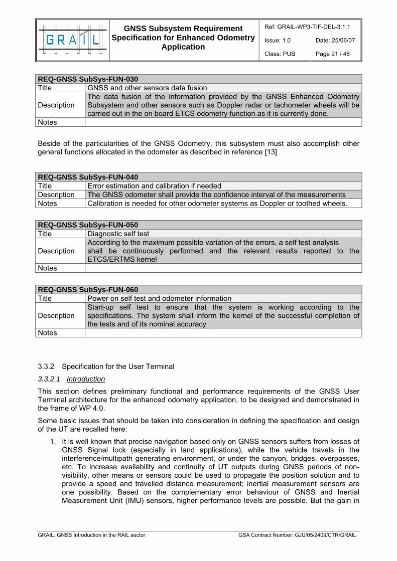
REQ-GNSS SubSys-FUN-030 Title GNSS and other sensors data fusion
Description The data fusion of the information provided by the GNSS Enhanced Odometry Subsystem and other sensors such as Doppler radar or tachometer wheels will be carried out in the on board ETCS odometry function as it is currently done.
Notes
Beside of the particularities of the GNSS Odometry, this subsystem must also accomplish other general functions allocated in the odometer as described in reference [13]
REQ-GNSS SubSys-FUN-040 Title Error estimation and calibration if needed Description The GNSS odometer shall provide the confidence interval of the measurements Notes Calibration is needed for other odometer systems as Doppler or toothed wheels.
REQ-GNSS SubSys-FUN-050 Title Diagnostic self test
Description According to the maximum possible variation of the errors, a self test analysis shall be continuously performed and the relevant results reported to the ETCS/ERTMS kernel
Notes
REQ-GNSS SubSys-FUN-060 Title Power on self test and odometer information
Description Start-up self test to ensure that the system is working according to the specifications. The system shall inform the kernel of the successful completion of the tests and of its nominal accuracy
Notes
3.3.2 Specification for the User Terminal
3.3.2.1 Introduction
This section defines preliminary functional and performance requirements of the GNSS User Terminal architecture for the enhanced odometry application, to be designed and demonstrated in the frame of WP 4.0.
Some basic issues that should be taken into consideration in defining the specification and design of the UT are recalled here:
1. It is well known that precise navigation based only on GNSS sensors suffers from losses of GNSS Signal lock (especially in land applications), while the vehicle travels in the interference/multipath generating environment, or under the canyon, bridges, overpasses, etc. To increase availability and continuity of UT outputs during GNSS periods of non-visibility, other means or sensors could be used to propagate the position solution and to provide a speed and travelled distance measurement; inertial measurement sensors are one possibility. Based on the complementary error behaviour of GNSS and Inertial Measurement Unit (IMU) sensors, higher performance levels are possible. But the gain in

Ref: GRAIL-WP3-TIF-DEL-3.1.1
Issue: 1.0 Date: 25/06/07
GNSS Subsystem Requirement Specification for Enhanced Odometry
Application Class: PUB Page 22 / 48
GRAIL: GNSS Introduction in the RAIL sector GSA Contract Number: GJU/05/2409/CTR/GRAIL
accuracy, availability, integrity and continuity depends also on the architecture of integration and data fusion. For ground applications such as railway navigation applications, the integration of an IMU with a GNSS receiver at user terminal level, consists in the combination of measurements generated by the independent sensors (accelerations, angular rate, position and velocity) using a data fusion techniques, such as Kalman filter technique.
Inertial Navigation Sensors and GNSS have several complementary properties: the inertial sensors have small errors over short times but drift over the long period, while the GNSS solution is able to maintain a more constant level of accuracy.
The GNSS system can provide absolute position, velocity and time estimates with bounded errors (this means that it is under bounded by a sphere or that it is possible to define a sphere radius containing at 95% of probability the error value). Those outputs need to be then transformed into a travelled distance measurement. The sample rate is not very high, typically a few Hertz, which is often too low for control purposes.
Inertial sensors, on the other hand, can provide measurements at higher sampling rates, but in the integration process the error is not bounded.
The fact that Inertial Navigation Sensors and GNSS have these complementary properties can be used advantageously, if the two systems are integrated.
2. Use of local elements (TBD): positioning accuracy can be improved locally by providing users with differential corrections. A differential reference station comprises a fixed receiver that measures pseudo-range to the satellites. Since the location of such a ground-station is precisely known, the differential correction can be calculated, enabling removal of most of the error component common to all users in the coverage area. Enhanced integrity information can also be provided on a local basis through utilization of Local Integrity Monitors. These can deliver enhancements with respect to all aspects of integrity provision, namely Time to Alarm, Alarm Limits and Risk of Missed Detections. On the other hand Local Elements can also include the use of “pseudolites” that is fixed transmitters that provide a “satellite-like” signal usable by the user receiver as an additional signal and measurement source. This feature allows overcoming the GNSS lack of visibility in areas with obstructed line of sight to the GNSS satellites.
The GNSS UT Navigation Equipment is in charge of providing an additional source of position and speed information (with respect to the traditional tachometer) to the ETCS Kernel in order to determine train speed and distance.
The functions that are in charge to the GNSS UT are:
Measure position and speed, and consequently generate the defined output data with the agreed protocol and format.
Process the data, that means:
1. Implement Data fusion process (sensor output elaboration, translation of coordinates, etc.) using navigation data acquired from Navigation Sensors.
2. Status determination (Diagnostic and self-test, Error estimation), verifying the overall GNSS UT Demonstrator functionality and maintain a fault log for diagnostic purpose. More in detail, the GNSS UT shall monitor the integrity of the SIS (including Local effects) and compute the confidence interval.
Ref: GRAIL-WP3-TIF-DEL-3.1.1
Issue: 1.0 Date: 25/06/07
GNSS Subsystem Requirement Specification for Enhanced Odometry
Application Class: PUB Page 23 / 48
GRAIL: GNSS Introduction in the RAIL sector GSA Contract Number: GJU/05/2409/CTR/GRAIL
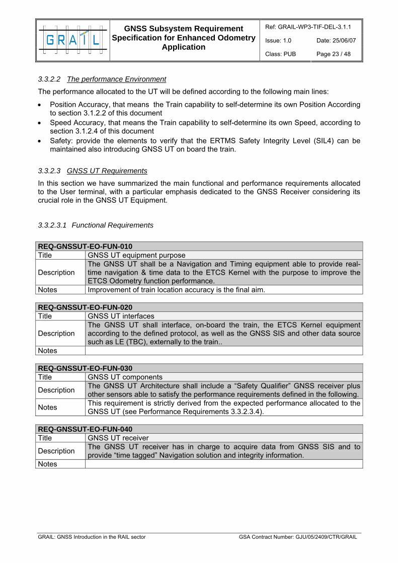
3.3.2.2 The performance Environment
The performance allocated to the UT will be defined according to the following main lines:
• Position Accuracy, that means the Train capability to self-determine its own Position According to section 3.1.2.2 of this document
• Speed Accuracy, that means the Train capability to self-determine its own Speed, according to section 3.1.2.4 of this document
• Safety: provide the elements to verify that the ERTMS Safety Integrity Level (SIL4) can be maintained also introducing GNSS UT on board the train.
3.3.2.3 GNSS UT Requirements
In this section we have summarized the main functional and performance requirements allocated to the User terminal, with a particular emphasis dedicated to the GNSS Receiver considering its crucial role in the GNSS UT Equipment.
3.3.2.3.1 Functional Requirements
REQ-GNSSUT-EO-FUN-010 Title GNSS UT equipment purpose
Description The GNSS UT shall be a Navigation and Timing equipment able to provide real-time navigation & time data to the ETCS Kernel with the purpose to improve the ETCS Odometry function performance.
Notes Improvement of train location accuracy is the final aim. REQ-GNSSUT-EO-FUN-020 Title GNSS UT interfaces
Description The GNSS UT shall interface, on-board the train, the ETCS Kernel equipment according to the defined protocol, as well as the GNSS SIS and other data source such as LE (TBC), externally to the train..
Notes REQ-GNSSUT-EO-FUN-030 Title GNSS UT components
Description The GNSS UT Architecture shall include a “Safety Qualifier” GNSS receiver plus other sensors able to satisfy the performance requirements defined in the following.
Notes This requirement is strictly derived from the expected performance allocated to the GNSS UT (see Performance Requirements 3.3.2.3.4).
REQ-GNSSUT-EO-FUN-040 Title GNSS UT receiver
Description The GNSS UT receiver has in charge to acquire data from GNSS SIS and to provide “time tagged” Navigation solution and integrity information.
Notes
Ref: GRAIL-WP3-TIF-DEL-3.1.1
Issue: 1.0 Date: 25/06/07
GNSS Subsystem Requirement Specification for Enhanced Odometry
Application Class: PUB Page 24 / 48
GRAIL: GNSS Introduction in the RAIL sector GSA Contract Number: GJU/05/2409/CTR/GRAIL
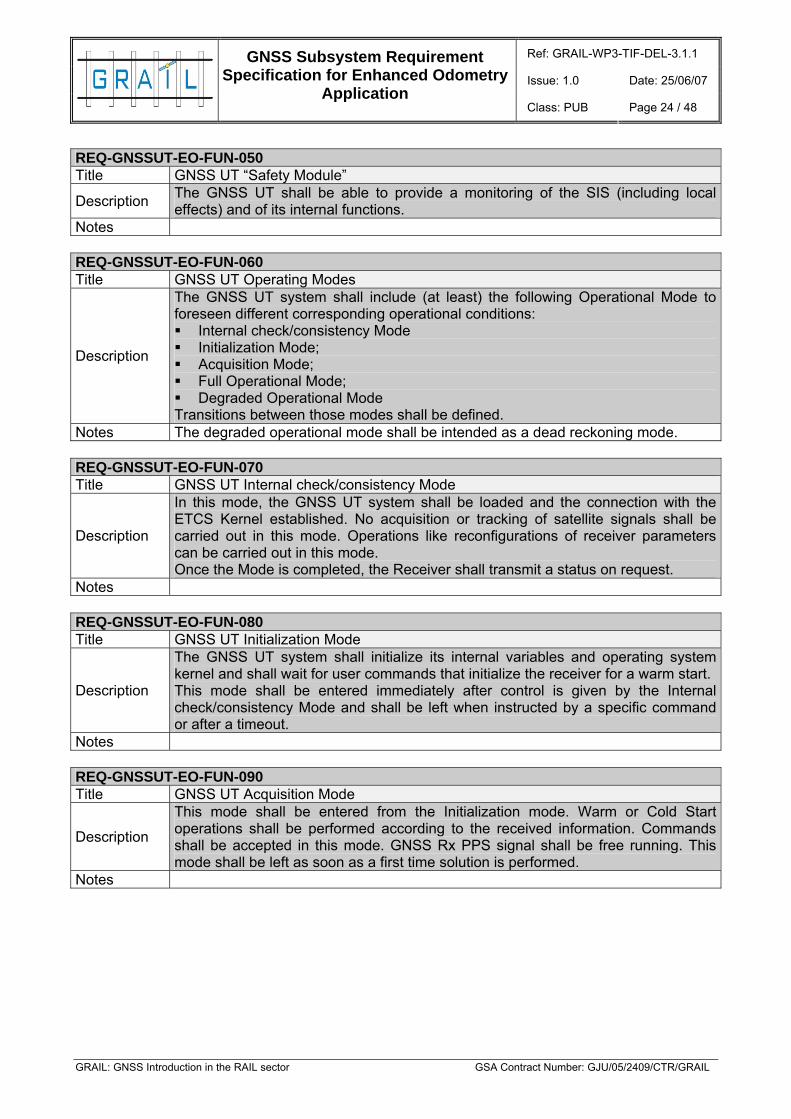
REQ-GNSSUT-EO-FUN-050 Title GNSS UT “Safety Module”
Description The GNSS UT shall be able to provide a monitoring of the SIS (including local effects) and of its internal functions.
Notes REQ-GNSSUT-EO-FUN-060 Title GNSS UT Operating Modes
Description
The GNSS UT system shall include (at least) the following Operational Mode to foreseen different corresponding operational conditions: Internal check/consistency Mode Initialization Mode; Acquisition Mode; Full Operational Mode; Degraded Operational Mode
Transitions between those modes shall be defined. Notes The degraded operational mode shall be intended as a dead reckoning mode. REQ-GNSSUT-EO-FUN-070 Title GNSS UT Internal check/consistency Mode
Description
In this mode, the GNSS UT system shall be loaded and the connection with the ETCS Kernel established. No acquisition or tracking of satellite signals shall be carried out in this mode. Operations like reconfigurations of receiver parameters can be carried out in this mode. Once the Mode is completed, the Receiver shall transmit a status on request.
Notes REQ-GNSSUT-EO-FUN-080 Title GNSS UT Initialization Mode
Description
The GNSS UT system shall initialize its internal variables and operating system kernel and shall wait for user commands that initialize the receiver for a warm start. This mode shall be entered immediately after control is given by the Internal check/consistency Mode and shall be left when instructed by a specific command or after a timeout.
Notes REQ-GNSSUT-EO-FUN-090 Title GNSS UT Acquisition Mode
Description
This mode shall be entered from the Initialization mode. Warm or Cold Start operations shall be performed according to the received information. Commands shall be accepted in this mode. GNSS Rx PPS signal shall be free running. This mode shall be left as soon as a first time solution is performed.
Notes

Ref: GRAIL-WP3-TIF-DEL-3.1.1
Issue: 1.0 Date: 25/06/07
GNSS Subsystem Requirement Specification for Enhanced Odometry
Application Class: PUB Page 25 / 48
GRAIL: GNSS Introduction in the RAIL sector GSA Contract Number: GJU/05/2409/CTR/GRAIL
REQ-GNSSUT-EO-FUN-100 Title GNSS UT Full Operational Mode
Description In this mode the GNSS UT shall perform its nominal Navigation and Integrity functions using all the available data.
Notes
Different operational sub-modes can be foreseen according to the available interfaces: 1. SIS-only Navigation Mode; 2. Inertial Measurements aided Navigation Mode (TBC) 3. Local Precision Navigation Mode (TBC) 4. TBC
REQ-GNSSUT-EO-FUN-110 Title GNSS UT Degraded Operational Mode
Description In this mode the GNSS UT shall perform its Navigation and Integrity functions without GNSS availability.
Notes The performance will be specified in the dedicated section. REQ-GNSSUT-EO-FUN-120 Title Unlocked GNSS Signals
Description When the GNSS RX does not provide navigation data, the UT shall be able to perform a propagation of the solution using available information to reconstruct the train position/velocity profile along-track with the required accuracy.
Notes Max duration of propagation with defined accuracy is TBD. REQ-GNSSUT-EO-FUN-130 Title GNSS Data acquisition/Reacquisition
Description The UT shall be able to detect the GNSS signal restarting, and to recalibrate kinematic information.
Notes With re-acquisition we intend here the GNSS SIS re-acquisition after a loss of signal.
REQ-GNSSUT-EO-FUN-140 Title UT data fusion
Description The UT should implement data fusion filter to blend GNSS data with other sensors data, to calculate the optimal estimate of the kinematic information.
Notes The data fusion can be implemented or not, according to UT internal architecture definition. TBD
REQ-GNSSUT-EO-FUN-150 Title Data Storage
Description The UT shall be able to store the acquired and processed data (including time-stamping) compliant with the specified file format.
Notes Req. valid only for demonstration purposes REQ-GNSSUT-EO-FUN-160 Title Error Log Description The UT shall be able to store in a dedicated file all the error messages. Notes Req. valid only for demonstration purposes

Ref: GRAIL-WP3-TIF-DEL-3.1.1
Issue: 1.0 Date: 25/06/07
GNSS Subsystem Requirement Specification for Enhanced Odometry
Application Class: PUB Page 26 / 48
GRAIL: GNSS Introduction in the RAIL sector GSA Contract Number: GJU/05/2409/CTR/GRAIL
3.3.2.3.2 Output Definition
REQ-GNSSUT-EO-OUT-010 Title UT Output Definition
Description
The GNSS UT shall provide in output the following information: Travelled distance (from power on or reset/trigger)- optional (REQ-GNSSUT-
EO-OUT-020, 030, 040, 070) Time stamp, UTC time (date of odometry vector) - Mandatory (REQ-
GNSSUT-EO-OUT-090, -100) Upper limit of confidence interval for travelled distance – Optional Mandatory
(REQ-GNSSUT-EO-OUT -050) Lower limit of confidence interval for travelled distance – Optional Mandatory
(REQ-GNSSUT-EO-OUT -050) Train speed – Mandatory (REQ-GNSSUT-EO-OUT -080) Train acceleration - Optional (REQ-GNSSUT-EO-OUT-120) Upper limit of confidence interval for speed – Mandatory (REQ-GNSSUT-EO-
OUT -060) Lower limit of confidence interval for speed – Mandatory (REQ-GNSSUT-EO-
OUT -060) Direction - Optional (REQ-GNSSUT-EO-OUT-110) Standstill – TBD (REQ-GNSSUT-EO-OUT-130) ID number of last reset balise - optional
Notes REQ-GNSSUT-EO-OUT-020 Title Travelled distance : Nominal
Description The GNSS UT shall transmit the nominal distance to the ETCS kernel. For any train movement, the GNSS UT shall be able to compute the most probable distance traveled using all the available measurement.
Notes REQ-GNSSUT-EO-OUT-030 Title Travelled distance : Resolution
Description
The GNSS UT shall transmit the resolution part to the ETCS kernel. The resolution part consists of all measurement accuracy limitations which does not grow with distance or time. Resolution part is defined as the non-accumulative limitation in precision of a single report. For any train movement, the GNSS UT shall be able to compute the most probable distance travelled using all the available measurement.
Notes
For odometers based on tachometer sensors the resolution part depends on the distance travelled for a pulse. As the sampling error can be almost one pulse in each direction the resolution part can be rounded to be the length travelled for one pulse counted. Further, a distance includes two endpoints, each adding to the resolution part, hence the distance resolution for this kind of sensor is the distance corresponding to (at least) two pulses. Moreover, Tachometer sensors typically have a constant resolution, as the distancetravelled for a pulse is not depending on speed or other factors. This is not necessarily true for other sensor technologies.

Ref: GRAIL-WP3-TIF-DEL-3.1.1
Issue: 1.0 Date: 25/06/07
GNSS Subsystem Requirement Specification for Enhanced Odometry
Application Class: PUB Page 27 / 48
GRAIL: GNSS Introduction in the RAIL sector GSA Contract Number: GJU/05/2409/CTR/GRAIL
REQ-GNSSUT-EO-OUT-040 Title Travelled distance : accumulative part
Description The GNSS UT shall be able to estimate the distance accumulative part defined as a parameter that changes in proportion to moved distance, but including all accumulative errors that brings estimation to the movement direction.
Notes REQ-GNSSUT-EO-OUT-050 Title Travelled distance : Confidence Interval
Description The GNSS UT shall be able to estimate the distance confidence interval by using all the available measurements
Notes
.
Figure 5: The travelled distance parameters
REQ-GNSSUT-EO-OUT-060 Title UT Confidence level
Description If not differently specified, the confidence level of GNSS UT defined in the frame of Enhanced Odometer application shall be intended as k=7.
Notes
The confidence level (K) is defined as a level of probability that the true position is inside the confidence interval. The confidence level is related to probability according to the table.

Ref: GRAIL-WP3-TIF-DEL-3.1.1
Issue: 1.0 Date: 25/06/07
GNSS Subsystem Requirement Specification for Enhanced Odometry
Application Class: PUB Page 28 / 48
GRAIL: GNSS Introduction in the RAIL sector GSA Contract Number: GJU/05/2409/CTR/GRAIL
REQ-GNSSUT-EO-OUT-070 Title Travelled distance: Trigger
Description The GNSS UT shall implement a reset command able to restart the distance information when required.
Notes OPTIONAL REQ-GNSSUT-EO-OUT-080 Title Speed
Description The speed information provided by GNSS UT shall be the absolute value of the Nominal speed of the train.
Notes REQ-GNSSUT-EO-OUT-090 Title Time Stamp
Description The time stamp provided by GNSS UT shall be the UTC time of the output information.
Notes REQ-GNSSUT-EO-OUT-100 Title GNSS Time
Description The GNSS Time provided by GNSS UT shall be the GNSS (GPS or GST TBD) time of the output information.
Notes REQ-GNSSUT-EO-OUT-110 Title Train movement direction
Description
The GNSS UT shall be able to provide Movement direction information of the train. According to Subset 035 we define: Positive movement direction is defined as movements going in the direction
of cab B to cab A. It shall be indicated with positive speed and increasing odometer distance values.
Negative movement direction is defined as movements going in the direction of cab A to cab B. It shall be indicated with negative speed and decreasing odometer distance values.
Notes
1. This requirement shall be considered as optional. 2. Allocation of cab A and cab B on specific train information is in charge to ETCS
On-board, then transmission information to UT shall be implemented, for example through configuration or initialization parameters.
REQ-GNSSUT-EO-OUT-120 Title Acceleration
Description The GNSS UT shall report to the ETCS on-board the along track acceleration value.
Notes This requirement shall be considered as optional REQ-GNSSUT-EO-OUT-130

Ref: GRAIL-WP3-TIF-DEL-3.1.1
Issue: 1.0 Date: 25/06/07
GNSS Subsystem Requirement Specification for Enhanced Odometry
Application Class: PUB Page 29 / 48
GRAIL: GNSS Introduction in the RAIL sector GSA Contract Number: GJU/05/2409/CTR/GRAIL
Title Standstill
Description At standstill the speed shall be zero. However vehicle vibration and jerk is allowed to give sporadic non-zero speed estimations. Threshold for standstill shall be defined.
Notes This requirement shall be considered as optional. REQ-GNSSUT-EO-OUT-140 Title Status
Description
The GNSS UT shall report to the ETCS on-board its configuration status. General status / integrity (enumerated) Values: Nominal safe mode, all confidence intervals are valid Disturbed non-safe mode, confidence intervals are not valid Failure non-safe mode, critical defect, no data Signal (enumerated) Values: Loss at the moment no satellite signal available Resumed signal is resumed, but there were periods of loss Ok all the time (since reference point/trigger) no loss Alarms (3 variables, all Boolean) Timeout: satellite information is not ready within the rate interval Suspicious satellite information is available, but not to be trusted Sensor: additional sensor defect
Notes
3.3.2.3.3 GNSS Scenarios definition and Requirements
Since the GNSS Enhanced Odometry Subsystem performances strongly depend on the environment, the enhanced odometry performance will be specified for precise configurations.
Two main environments will be considered:
• A rural environment with a good satellite visibility and low probability of indirect paths (typical cases to be defined to describe the rural environment)
• An urban environment corresponding to an area with less satellite visibility and height probability of indirect paths (typical cases to be defined to describe the urban environment).
For each environment, performances are given in the following section.
Ref: GRAIL-WP3-TIF-DEL-3.1.1
Issue: 1.0 Date: 25/06/07
GNSS Subsystem Requirement Specification for Enhanced Odometry
Application Class: PUB Page 30 / 48
GRAIL: GNSS Introduction in the RAIL sector GSA Contract Number: GJU/05/2409/CTR/GRAIL
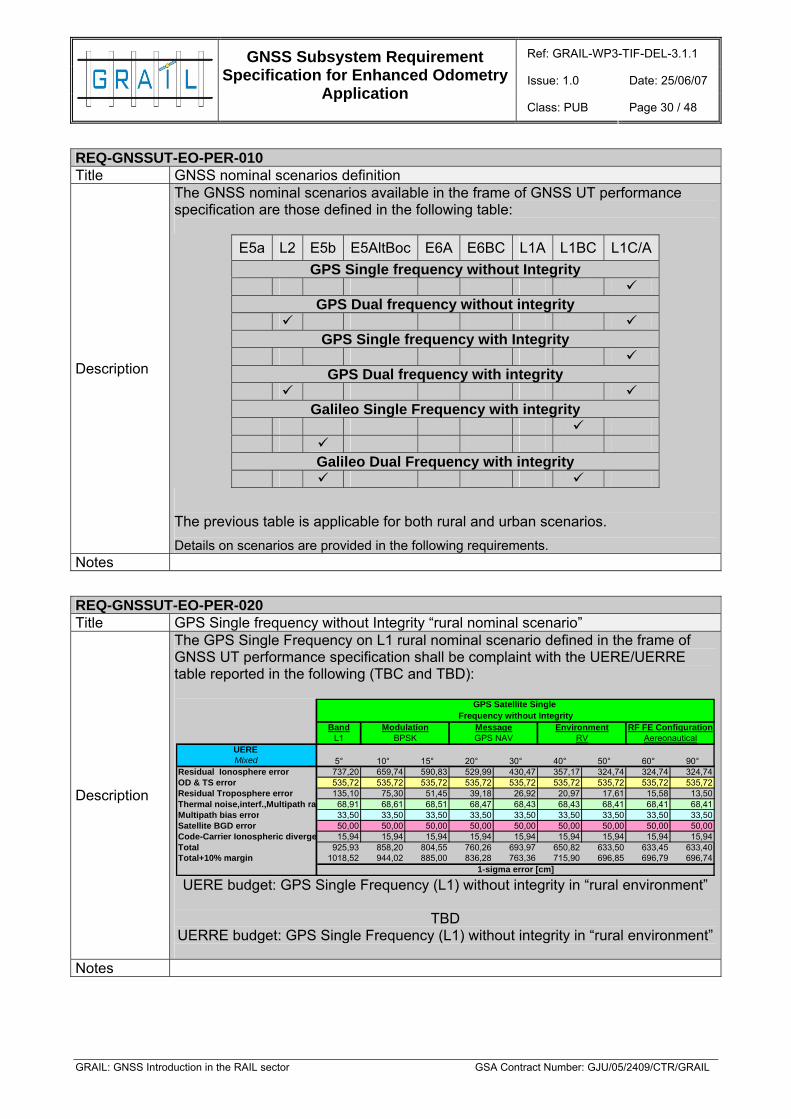
REQ-GNSSUT-EO-PER-010 Title GNSS nominal scenarios definition
Description
The GNSS nominal scenarios available in the frame of GNSS UT performance specification are those defined in the following table:
E5a L2 E5b E5AltBoc E6A E6BC L1A L1BC L1C/A GPS Single frequency without Integrity
GPS Dual frequency without integrity
GPS Single frequency with Integrity
GPS Dual frequency with integrity
Galileo Single Frequency with integrity
Galileo Dual Frequency with integrity
The previous table is applicable for both rural and urban scenarios. Details on scenarios are provided in the following requirements.
Notes
REQ-GNSSUT-EO-PER-020 Title GPS Single frequency without Integrity “rural nominal scenario”
Description
The GPS Single Frequency on L1 rural nominal scenario defined in the frame of GNSS UT performance specification shall be complaint with the UERE/UERRE table reported in the following (TBC and TBD):
BandL1
UERE Mixed
Residual Ionosphere error 737,20 659,74 590,83 529,99 430,47 357,17 324,74 324,74 324,74OD & TS error 535,72 535,72 535,72 535,72 535,72 535,72 535,72 535,72 535,72Residual Troposphere error 135,10 75,30 51,45 39,18 26,92 20,97 17,61 15,58 13,50Thermal noise,interf.,Multipath ra 68,91 68,61 68,51 68,47 68,43 68,43 68,41 68,41 68,41Multipath bias error 33,50 33,50 33,50 33,50 33,50 33,50 33,50 33,50 33,50Satellite BGD error 50,00 50,00 50,00 50,00 50,00 50,00 50,00 50,00 50,00Code-Carrier Ionospheric diverge 15,94 15,94 15,94 15,94 15,94 15,94 15,94 15,94 15,94Total 925,93 858,20 804,55 760,26 693,97 650,82 633,50 633,45 633,40Total+10% margin 1018,52 944,02 885,00 836,28 763,36 715,90 696,85 696,79 696,74
GPS Satellite Single
BPSK GPS NAV
Frequency without IntegrityModulation Message Environment RF FE Configuration
5° 10° 15° 20° 90°
1-sigma error [cm]
RV Aereonautical
30° 40° 50° 60°
UERE budget: GPS Single Frequency (L1) without integrity in “rural environment”
TBD UERRE budget: GPS Single Frequency (L1) without integrity in “rural environment”
Notes

Ref: GRAIL-WP3-TIF-DEL-3.1.1
Issue: 1.0 Date: 25/06/07
GNSS Subsystem Requirement Specification for Enhanced Odometry
Application Class: PUB Page 31 / 48
GRAIL: GNSS Introduction in the RAIL sector GSA Contract Number: GJU/05/2409/CTR/GRAIL
REQ-GNSSUT-EO-PER-030 Title GPS Dual frequencies without Integrity “rural nominal scenario”
Description
The GPS Dual Frequencies rural nominal scenario defined in the frame of GNSS UT performance specification shall be complaint with the UERE/UERRE table reported in the following (TBC and TBD):
BandL1
UERE Mixed
Residual Ionosphere error 184,30 164,94 147,71 132,50 107,62 89,29 81,19 81,19 81,19OD & TS error 133,93 133,93 133,93 133,93 133,93 133,93 133,93 133,93 133,93Residual Troposphere error 33,77 18,82 12,86 9,79 6,73 5,24 4,40 3,90 3,38Thermal noise,interf.,Multipath ra 68,91 68,61 68,51 68,47 68,43 68,43 68,41 68,41 68,41Multipath bias error 33,50 33,50 33,50 33,50 33,50 33,50 33,50 33,50 33,50Satellite BGD error 50,00 50,00 50,00 50,00 50,00 50,00 50,00 50,00 50,00Code-Carrier Ionospheric diverge 15,94 15,94 15,94 15,94 15,94 15,94 15,94 15,94 15,94Total 248,33 232,55 220,20 210,13 195,25 185,73 181,95 181,93 181,92Total+10% margin 273,17 255,80 242,22 231,14 214,78 204,31 200,14 200,13 200,11
RV Aereonautical
GPS Satellite doubleFrequency without Integrity
Modulation Message Environment RF FE Configuration
15° 20°
BPSK GPS NAV
90°
1-sigma error [cm]
30° 40° 50° 60°5° 10°
UERE budget: GPS Dual Frequencies without integrity in “rural environment”
TBD
UERRE budget: GPS Dual Frequencies without integrity in “rural environment” Notes
REQ-GNSSUT-EO-PER-040 Title GPS Single frequency with Integrity “rural nominal scenario”
Description
The GPS Single Frequency on L1 rural nominal scenario defined in the frame of GNSS UT performance specification shall be complaint with the UERE/UERRE table reported in the following (TBC and TBD):
TBD UERE budget: GPS Single Frequency (L1) with integrity in “rural environment”
TBD
UERRE budget: GPS Single Frequency (L1) with integrity in “rural environment” Notes
REQ-GNSSUT-EO-PER-050 Title GPS Dual frequencies with Integrity “rural nominal scenario”
Description
The GPS Dual Frequencies rural nominal scenario defined in the frame of GNSS UT performance specification shall be complaint with the UERE/UERRE table reported in the following (TBC and TBD):
TBD UERE budget: GPS Dual Frequencies with integrity in “rural environment”
TBD
UERRE budget: GPS Dual Frequencies with integrity in “rural environment” Notes

Ref: GRAIL-WP3-TIF-DEL-3.1.1
Issue: 1.0 Date: 25/06/07
GNSS Subsystem Requirement Specification for Enhanced Odometry
Application Class: PUB Page 32 / 48
GRAIL: GNSS Introduction in the RAIL sector GSA Contract Number: GJU/05/2409/CTR/GRAIL
REQ-GNSSUT-EO-PER-060 Title Galileo Single Frequency on L1 with integrity “rural nominal scenario”
Description
The Galileo Single Frequency on L1 rural nominal scenarios defined in the frame of GNSS UT performance specification shall be complaint with the UERE/UERRE table defined in the TUSREQ document and reported in the following:
UERE budget: Galileo Single Frequency (L1) in “rural environment”
UERRE budget (200ms): Galileo Single Frequency (L1) in “rural environment”
Notes TUS Identifier N°15

Ref: GRAIL-WP3-TIF-DEL-3.1.1
Issue: 1.0 Date: 25/06/07
GNSS Subsystem Requirement Specification for Enhanced Odometry
Application Class: PUB Page 33 / 48
GRAIL: GNSS Introduction in the RAIL sector GSA Contract Number: GJU/05/2409/CTR/GRAIL
REQ-GNSSUT-EO-PER-070 Title Galileo Single Frequency on E5b with integrity “rural nominal scenario”
Description
The Galileo Single Frequency on E5b rural nominal scenarios defined in the frame of GNSS UT performance specification shall be complaint with the UERE/UERRE table defined in the TUSREQ document and reported in the following:
UERE budget: Galileo Single Frequency (E5b) in “rural environment”
UERRE budget (200ms): Galileo Single Frequency (E5b) in “rural environment”
Notes TUS Identifier N°16

Ref: GRAIL-WP3-TIF-DEL-3.1.1
Issue: 1.0 Date: 25/06/07
GNSS Subsystem Requirement Specification for Enhanced Odometry
Application Class: PUB Page 34 / 48
GRAIL: GNSS Introduction in the RAIL sector GSA Contract Number: GJU/05/2409/CTR/GRAIL
REQ-GNSSUT-EO-PER-080 Title Galileo Dual Frequencies with integrity “rural nominal scenario”
Description
The Galileo Dual Frequencies rural nominal scenario defined in the frame of GNSS UT performance specification shall be complaint with the UERE/UERRE table defined in the TUSREQ document and reported in the following:
UERE budget: Galileo Dual Frequencies in “rural environment”
UERRE budget (200ms):Galileo Dual Frequencies in “rural environment”
Notes TUS Identifier N°19
REQ-GNSSUT-EO-PER-090 Title GPS Single frequency without Integrity “urban nominal scenario”
Description
The GPS Single Frequency on L1 urban nominal scenario defined in the frame of GNSS UT performance specification shall be complaint with the UERE/UERRE table reported in the following (TBC and TBD):
TBD UERE budget: GPS Single Frequency (L1) without integrity in “urban environment”
TBD
UERRE budget: GPS Single Frequency (L1) without integrity in “urban environment”
Notes
Ref: GRAIL-WP3-TIF-DEL-3.1.1
Issue: 1.0 Date: 25/06/07
GNSS Subsystem Requirement Specification for Enhanced Odometry
Application Class: PUB Page 35 / 48
GRAIL: GNSS Introduction in the RAIL sector GSA Contract Number: GJU/05/2409/CTR/GRAIL
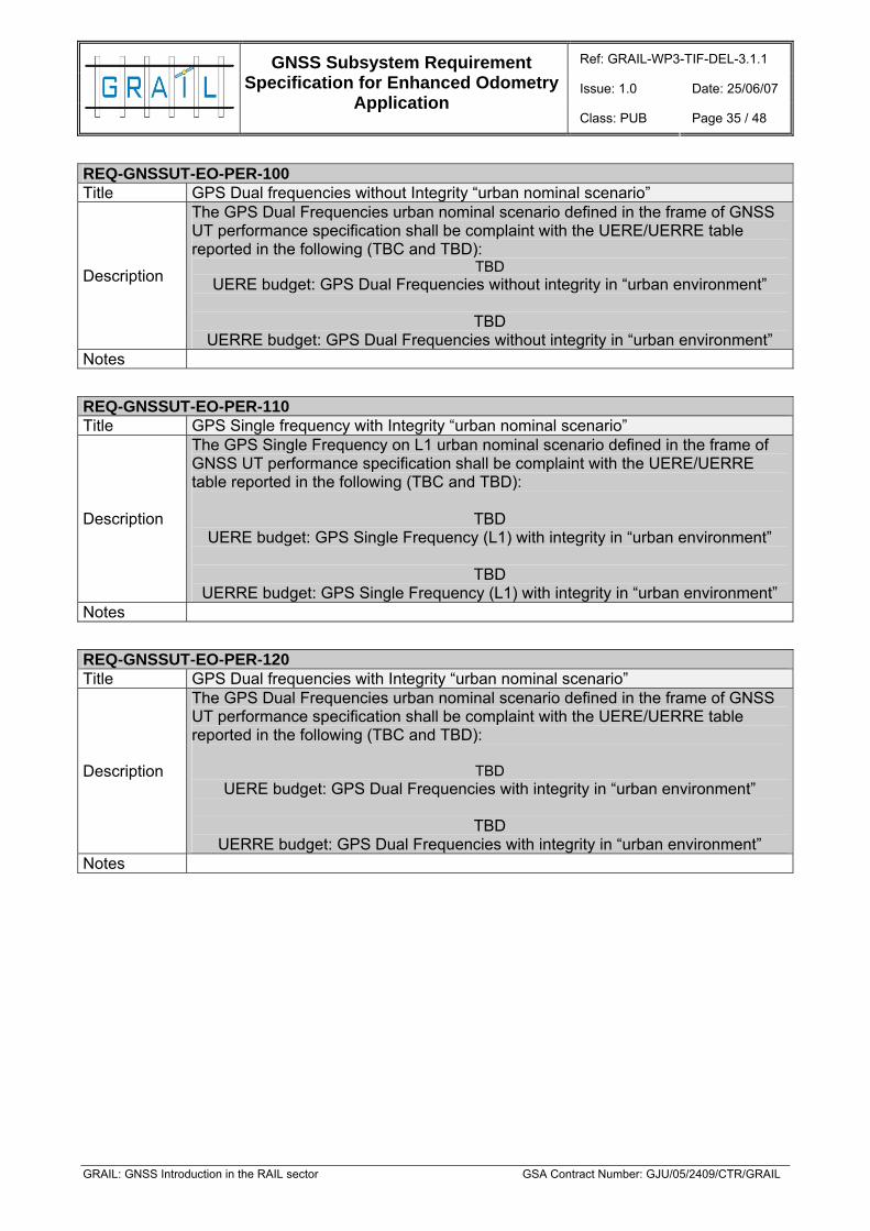
REQ-GNSSUT-EO-PER-100 Title GPS Dual frequencies without Integrity “urban nominal scenario”
Description
The GPS Dual Frequencies urban nominal scenario defined in the frame of GNSS UT performance specification shall be complaint with the UERE/UERRE table reported in the following (TBC and TBD):
TBD UERE budget: GPS Dual Frequencies without integrity in “urban environment”
TBD
UERRE budget: GPS Dual Frequencies without integrity in “urban environment” Notes
REQ-GNSSUT-EO-PER-110 Title GPS Single frequency with Integrity “urban nominal scenario”
Description
The GPS Single Frequency on L1 urban nominal scenario defined in the frame of GNSS UT performance specification shall be complaint with the UERE/UERRE table reported in the following (TBC and TBD):
TBD UERE budget: GPS Single Frequency (L1) with integrity in “urban environment”
TBD
UERRE budget: GPS Single Frequency (L1) with integrity in “urban environment” Notes
REQ-GNSSUT-EO-PER-120 Title GPS Dual frequencies with Integrity “urban nominal scenario”
Description
The GPS Dual Frequencies urban nominal scenario defined in the frame of GNSS UT performance specification shall be complaint with the UERE/UERRE table reported in the following (TBC and TBD):
TBD UERE budget: GPS Dual Frequencies with integrity in “urban environment”
TBD
UERRE budget: GPS Dual Frequencies with integrity in “urban environment” Notes

Ref: GRAIL-WP3-TIF-DEL-3.1.1
Issue: 1.0 Date: 25/06/07
GNSS Subsystem Requirement Specification for Enhanced Odometry
Application Class: PUB Page 36 / 48
GRAIL: GNSS Introduction in the RAIL sector GSA Contract Number: GJU/05/2409/CTR/GRAIL
REQ-GNSSUT-EO-PER-130 Title Galileo Single Frequency on L1 with integrity “urban nominal scenario”
Description
The Galileo Single Frequency on L1 urban nominal scenarios defined in the frame of GNSS UT performance specification shall be complaint with the UERE/UERRE table defined in the TUSREQ document and reported in the following:
TBD UERE budget: Galileo Single Frequency (L1) in “urban environment”
TBD
UERRE budget (200ms): Galileo Single Frequency (L1) in “urban environment”
Notes
REQ-GNSSUT-EO-PER-140 Title Galileo Single Frequency on E5b with integrity “urban nominal scenario”
Description
The Galileo Single Frequency on E5b urban nominal scenarios defined in the frame of GNSS UT performance specification shall be complaint with the UERE/UERRE table defined in the TUSREQ document and reported in the following:
TBD
UERE budget: Galileo Single Frequency (E5b) in “urban environment”
TBD
UERRE budget (200ms): Galileo Single Frequency (E5b) in “urban environment”
Notes
REQ-GNSSUT-EO-PER-150 Title Galileo Dual Frequencies with integrity “urban nominal scenario”
Description
The Galileo Dual Frequencies urban nominal scenario defined in the frame of GNSS UT performance specification shall be complaint with the UERE/UERRE table defined in the TUSREQ document and reported in the following:
TBD
UERE budget: Galileo Dual Frequencies in “urban environment”
UERRE budget (200ms):Galileo Dual Frequencies in “urban environment” Notes
3.3.2.3.4 Performance Requirements
REQ-GNSSUT-EO-PER-160 Title Reset
Description The GNSS UT shall be able to reset distance measurement (as well as associated errors) at least 3 seconds or 1 meter after the reference point information (trigger).
Notes OPTIONAL

Ref: GRAIL-WP3-TIF-DEL-3.1.1
Issue: 1.0 Date: 25/06/07
GNSS Subsystem Requirement Specification for Enhanced Odometry
Application Class: PUB Page 37 / 48
GRAIL: GNSS Introduction in the RAIL sector GSA Contract Number: GJU/05/2409/CTR/GRAIL
REQ-GNSSUT-EO-PER-170 Title Travelled Distance Accuracy
Description
The GNSS UT using data generated by GNSS UT sensors shall provide a Travelled Distance accuracy of 5% (TBC) (of travelled distance) independently of the speed and operational conditions. The accuracy requirement shall depend on the GNSS UT operational conditions as follows:
GNSS Availability Accuracies (m) GPS Egnos Galileo with integrity Urban Rural
Single freq. No Dual freq No
Single freq. Yes Dual freq Yes
Single freq on L1BC Single freq on E5b Dual freq on L1BC/E5b
no no no
1. . Notes REQ-GNSSUT-EO-PER-180 Title Travelled Distance confidence interval
Description
The GNSS UT system shall provide, the confidence interval related to the "safe front-end" position of the train of 5m (TBC). This confidence interval shall be given with a 5σ TBC probability (1e-5). The accuracy requirement shall depend on the GNSS UT operational conditions as follows:
GNSS Availability Accuracies (m) GPS Egnos Galileo with integrity Urban Rural
Single freq. No Dual freq No
Single freq. Yes Dual freq Yes
Single freq on L1BC Single freq on E5b Dual freq on L1BC/E5b
no no no
1. .
Notes
The confidence interval on the safe front-end may be computed as the sum of a fixed offset between the selected reference point (eg. the antenna position for the GNSS receiver) and the train front-end and by the position protection level radius. The accuracy value reported here is derived from SUBSET 059.

Ref: GRAIL-WP3-TIF-DEL-3.1.1
Issue: 1.0 Date: 25/06/07
GNSS Subsystem Requirement Specification for Enhanced Odometry
Application Class: PUB Page 38 / 48
GRAIL: GNSS Introduction in the RAIL sector GSA Contract Number: GJU/05/2409/CTR/GRAIL
REQ-GNSSUT-EO-PER-190 Title Speed Accuracy
Description
The GNSS UT using data generated by GNSS UT sensors shall provide a speed accuracy of 2 km/h independently of operational conditions.
The accuracy requirement shall depend on the GNSS UT operational conditions as follows:
GNSS Availability
Accuracies (m/s)
GPS Egnos Galileo with integrity Urban Rural Single freq. No Dual freq No
Single freq. Yes Dual freq Yes
Single freq on L1BC Single freq on E5b Dual freq on L1BC/E5b
no no no
1. : 2.
Notes The accuracy value reported here are derived from SUBSET 059. REQ-GNSSUT-EO-PER-200 Title Availability
Description The Accuracies specified above shall be met for 95% of the time, in any place within the service volume, when operating in the Nominal SIS Constellation state.
Notes
Availability is defined here as the percentage of time that the GNSS UT navigation system is available for use over a given operation period. This is the percentage of time it provides the required function and performance in terms of position/velocity accuracy.
REQ-GNSSUT-EO-PER-210 Title Continuity
Description
The probability of service discontinuity predicted over the next critical operation period (15 sec TBC) shall not exceed the specified value of 8.0E-5 (TBC) assuming the SoL core system performance requirements (without receiver contribution) of 8.0E-6 on 15 sec.
Notes
Continuity requirement is related to the probability that the system's signal will meet accuracy and integrity requirements continuously for a specified period. Service volume is the area of coverage for which the system's signal will meet availability requirements. The continuity of the signal has been assured without additional facilities or funding.

Ref: GRAIL-WP3-TIF-DEL-3.1.1
Issue: 1.0 Date: 25/06/07
GNSS Subsystem Requirement Specification for Enhanced Odometry
Application Class: PUB Page 39 / 48
GRAIL: GNSS Introduction in the RAIL sector GSA Contract Number: GJU/05/2409/CTR/GRAIL
REQ-GNSSUT-EO-PER-220 Title Integrity Description The GNSS UT integrity shall be > TBD %
Notes
Integrity is defined here as the ability of the GNSS UT equipment to provide timely warnings to the user when data provided by the system should not be used. This definition is related to ability to avoid output of misleading information, that is providing data that has an error larger than the defined protection level without any indication of the error.
REQ-GNSSUT-EO-PER-230 Title Time to Alert Description The GNSS UT Time to Alert shall be better than 5 sec. Notes REQ-GNSSUT-EO-PER-240 Title Common Reference Time – Accuracy
Description
The GNSS UT shall time stamp data received from all equipment with a common reference time. This time should be based on the GNSS receiver PPS signal and PPS creation of data. Accuracy of this creation of data shall be such that the maximum induced error on position determination shall be less than TBC m.
Notes
3.3.2.3.5 Operational requirements
REQ-GNSSUT-EO-OPE-010 Title Acceleration range
Description The GNSS UT shall be able to operate in the following range of acceleration: ± 4 m/sec2
Notes REQ-GNSSUT-EO-OPE-020 Title Speed range
Description The GNSS UT shall be able to operate in the following range of speed : 0 - 500 km/hour.
Notes
3.3.2.3.6 Environmental Requirements
To be completed

Ref: GRAIL-WP3-TIF-DEL-3.1.1
Issue: 1.0 Date: 25/06/07
GNSS Subsystem Requirement Specification for Enhanced Odometry
Application Class: PUB Page 40 / 48
GRAIL: GNSS Introduction in the RAIL sector GSA Contract Number: GJU/05/2409/CTR/GRAIL
3.3.2.3.7 Interface Requirements
REQ-GNSSUT-EO-INT-010 Title GNSS UT external interfaces
Description The GNSS UT shall interface, externally, the ETCS Kernel equipment according to the communication and protocol specified in [15]
Notes REQ-GNSSUT-EO-INT-020 Title GNSS UT internal interfaces
Description The GNSS UT shall interface, internally, the GNSS Rx equipment according to the communication and protocol specified in the following. The interfaces with additional navigation sensors shall be considered as proprietary.
Notes REQ-GNSSUT-EO-INT-030 Title GNSS UT Communication
Description The GNSS UT shall be able to handle the communication with the internal and external devices defined above through a profibus line
Notes REQ-GNSSUT-EO-INT-040 Title GNSS UT Commands/packets
Description The GNSS UT shall be able to send and receive periodic and/or sporadic Commands/packets and to execute received commands.
Notes
3.3.2.3.8 GNSS UT data exchange
REQ-GNSSUT-EO-DAT-010 Title GNSS UT check/consistency Data
Description
When in Internal check/consistency Mode, the GNSS UT shall be able to send packet/packets containing at least the following information: Communication results Internal check results TBC
Notes

Ref: GRAIL-WP3-TIF-DEL-3.1.1
Issue: 1.0 Date: 25/06/07
GNSS Subsystem Requirement Specification for Enhanced Odometry
Application Class: PUB Page 41 / 48
GRAIL: GNSS Introduction in the RAIL sector GSA Contract Number: GJU/05/2409/CTR/GRAIL
REQ-GNSSUT-EO-DAT-020 Title GNSS UT Configuration Data
Description
When in Initialization Mode, the GNSS UT shall be able to receive and validate (TBC) the Configuration data packet/packets containing at least the following information: Cycle time TBC
If no data are available, the GNSS UT shall be able to validate and use internally stored data
Notes
REQ-GNSSUT-EO-DAT-030 Title GNSS UT Initialization Data
Description
When in Initialization Mode, the GNSS UT shall be able to receive and validate (TBC) the Initialization data packet/packets containing at least the following information: Initial ECEF position/velocity Navigation Almanac Enabling GPS/EGNOS/GALILEO satellite positioning Local Elements use/do not use TBC
If no data are available, the GNSS UT shall be able to validate and use internally stored data.
Notes
REQ-GNSSUT-EO-DAT-040 Title GNSS UT Acquisition Mode Data
Description
When in GNSS Acquisition Mode, the GNSS UT shall be able to send packet/packets containing at least the following information: Tracked satellite TBC
This packet/packets shall be periodical with a frequency of TBD Hz. Notes

Ref: GRAIL-WP3-TIF-DEL-3.1.1
Issue: 1.0 Date: 25/06/07
GNSS Subsystem Requirement Specification for Enhanced Odometry
Application Class: PUB Page 42 / 48
GRAIL: GNSS Introduction in the RAIL sector GSA Contract Number: GJU/05/2409/CTR/GRAIL
REQ-GNSSUT-EO-DAT-050 Title GNSS UT Status Data
Description
The GNSS UT shall be able to send “Status Data” packet/packets containing at least the following information: GNSS UT operational Mode GNSS Rx PVT solution Type GNSS UT solution parameters (filter convergence data, TBC) Additional sensors status Failures (enumerated)
Code of component:: Antenna, CPU, RAM, ROM, power supply, additional sensors…
Self-test indication
progress counters of all components where selftests should run TBC
These packet/packets shall be on request (TBC). It should used a transport protocol providing data integrity detecting N-bit errors, sequence errors, data loss and data duplication.
Notes
REQ-GNSSUT-EO-DAT-060 Title GNSS UT Data Packets
Description The Data packets shall be configured according to “Interface Specification for Enhanced Odometry”.
Notes

Ref: GRAIL-WP3-TIF-DEL-3.1.1
Issue: 1.0 Date: 25/06/07
GNSS Subsystem Requirement Specification for Enhanced Odometry
Application Class: PUB Page 43 / 48
GRAIL: GNSS Introduction in the RAIL sector GSA Contract Number: GJU/05/2409/CTR/GRAIL
3.3.2.3.9 UT GNSS Receiver Specifications
REQ-GNSSUT-EO-RX-010 Title GNSS Receiver Architecture
Description
The GNSS receiver architecture should include the following general functions. The GNSS Receiver provides measurements and navigation messages from the following Navigation Satellites Systems:
- Global Positioning System (GPS) - GALILEO - Satellite Based Augmentation Systems (EGNOS/WAAS)
The GNSS Receiver Unit will provide the following functions: - Radio Frequency Conversion:
amplification and filtering of satellite signals down-conversion of the signals to base-band analog-digital conversion
- Digital Signal Processing: acquisition and tracking of code and carrier phase of all in-view satellites demodulation of the navigation messages computation of raw measurements (pseudo-range, Doppler)
- Navigation Data Processing: navigation message decoding PVT computation
- Error Reduction: multipath effect detection and mitigation interference effect detection and mitigation
- Receiver Control: mode selection according to command inputs process control self test status indication I/O function
- Signal Processing functions: They refer to all the functions related to control of the channels operations and processing of the observables. They perform:
Acquisition, Tracking and demodulation functions for each channel Pre-processing of observables to produce raw measurements both for
navigation and observation modes - Tracking list generation: Implements the high level satellites search and selection strategy. Builds and updates the receiver tracking lists and provides all the necessary information to the Signal Processing Modules in order to perform acquisition and tracking.
Notes REQ-GNSSUT-EO-RX-020 Title Antenna Pointing
Description The receiver SW shall assume a zenith-pointing antenna for the purpose of calculating satellites elevation with respect to the local horizontal
Notes

Ref: GRAIL-WP3-TIF-DEL-3.1.1
Issue: 1.0 Date: 25/06/07
GNSS Subsystem Requirement Specification for Enhanced Odometry
Application Class: PUB Page 44 / 48
GRAIL: GNSS Introduction in the RAIL sector GSA Contract Number: GJU/05/2409/CTR/GRAIL
REQ-GNSSUT-EO-RX-030 Title Number of channels Description The receiver should provide at least TBD channels. Notes Req. to be detailed with allocation of channels to GPS/Galileo/EGNOS-WAAS REQ-GNSSUT-EO-RX-040 Title GNSS receiver functionality
Description
The GNSS receiver shall provide the following main functions: - Control GNSS receiver channels, to perform acquisition, tracking, demodulation
and decoding of the GNSS SVs (GPS, GALILEO, GLONASS (optional) and EGNOS);
- Maintain knowledge of the GNSS SVs constellations in order to update channels tracking lists and always keep the highest number of visible SVs signals in lock;
- Derive phase and doppler measurements from GNSS signals and use them to compute navigation (position and velocity) and timing solutions;
- Provide to the on-board equipment a precise synchronization signal (Pulse Per Second) that can be used to synchronize different units.
Notes REQ-GNSSUT-EO-RX-050 Title Output Measurements
Description
The receiver should be able to produce at each measurement epoch the following raw measurements: - Pseudo-range measurement from C/A code from GPS, EGNOS L1,
GALILEO SOL (L1, E5b). - - Data Time Tag in GPS or GALILEO or UTC time - Channel status data: - Space Vehicle identifier - Receiver Channel identifier - Receiver channel status - Detected cycle slips information - Codeless tracking mode (GPS AS status) - Estimated Carrier SNR on L1, L2, E5 - Satellite Azimuth and elevation
Notes REQ-GNSSUT-EO-RX-060 Title PVT solution
Description
The GNSS receiver shall compute a navigation state vector composed of the following elements:
Three position coordinates Three velocity coordinates Receiver clock bias Receiver clock bias rate Time tag of solution
Notes

Ref: GRAIL-WP3-TIF-DEL-3.1.1
Issue: 1.0 Date: 25/06/07
GNSS Subsystem Requirement Specification for Enhanced Odometry
Application Class: PUB Page 45 / 48
GRAIL: GNSS Introduction in the RAIL sector GSA Contract Number: GJU/05/2409/CTR/GRAIL
REQ-GNSSUT-EO-RX-070 Title PVT solution algorithm
Description The receiver PVT solution shall be an instantaneous fix, based on a Least Squares algorithm and not filtered or propagated by internal models.
Notes REQ-GNSSUT-EO-RX-080 Title Reference frame
Description The receiver PVT solution output shall be referenced to the ECEF WGS84 reference frame. The output shall be Cartesian coordinates and/or Latitude, Longitude, Altitude.
Notes REQ-GNSSUT-EO-RX-090 Title Output navigation message
Description The receiver should be able to provide as output the decoded navigation messages from GPS, GALILEO and EGNOS.
Notes REQ-GNSSUT-EO-RX-100 Title Dynamics
Description The receiver signal processing acquisition and tracking loops shall be able to sustain the typical dynamics of the rail application.
Notes All performance requirements should be met under those dynamics conditions. REQ-GNSSUT-EO-RX-110 Title Initialization and First Position Fix Description The GNSS Rx will be able to operate in Cold and Warm start.
Notes
A cold start is defined when no initialization data is provided to the receiver and no previous history is internally available. A warm start is instead defined when the receiver is provided at switch-on with coarse information on the train position and with GNSS Almanac data. Alternatively a warm start could be considered, if the receiver had previously stored computed navigation information and GNSS Almanac data and the time elapsed from the last switch-off is below a given
REQ-GNSSUT-EO-RX-120 Title Initialization Information
Description
Initialization data (e.g. SV Almanacs, system time, etc.) downloaded from the constellation shall have priority on data loaded by user. This means that at user load, the receiver performs a check on the available information from the constellation before using it.
Notes

Ref: GRAIL-WP3-TIF-DEL-3.1.1
Issue: 1.0 Date: 25/06/07
GNSS Subsystem Requirement Specification for Enhanced Odometry
Application Class: PUB Page 46 / 48
GRAIL: GNSS Introduction in the RAIL sector GSA Contract Number: GJU/05/2409/CTR/GRAIL
REQ-GNSSUT-EO-RX-130 Title Warm start data
Description
For a warm start the receiver shall accept any of the following input data from the user: GNSS SVs Almanac; User receiver Cartesian or LLA position; Current time;
Notes REQ-GNSSUT-EO-RX-140 Title Time To Alarm
Description
The GNSS receiver shall provide an indication or output of the loss of navigation capability within 2 sec of the occurrence of any of the following conditions: • detected equipment malfunction or failure; • presence of conditions where there are an inadequate number of usable
satellites to compute PVT; • presence of condition where the fault detection detects a position failure
(exceed the protection level) which cannot be excluded within the time-to-alert. Notes REQ-GNSSUT-EO-RX-150 Title Multipath mitigation
Description Multipath rejection and mitigation techniques should be implemented in the GNSS receiver.
Notes
A strong multipath environment is expected in the railway environment specially when the train travels in urban environments, canyons or is in the station. Typically multipath mitigation techniques involve the antenna design or the design of the receiver signal processing function. The effect of multipath would be to increase the error in code phase measurements and consequently in the final navigation
REQ-GNSSUT-EO-RX-160 Title Interference mitigation
Description Suitable Interference mitigation techniques should be implemented in the GNSS receiver.
Notes
REQ-GNSSUT-EO-RX-170 Title Fast Re-acquisition
Description
To maximize the availability of the navigation, the GNSS receiver shall accept input signal predictions, including velocity and acceleration and (optionally) estimated range data, in order to aid the signal search and acquisition algorithms. Signal reacquisition time of better than 3 sec (TBC) shall be achieved after a satellite returns in view with the following aiding accuracy from the propagation filter: velocity estimation error < TBD m/sec, acceleration estimation error < TBD m/sec2, (optional) range estimation error < 1000 m.
Notes The GNSS UT will not be able to continue to track the GNSS signal when the train will be in the tunnels or in canyons. In the absence of a GNSS PVT solution, a propagator may propagate the position and aid the re-acquisition when exiting the tunnel.

Ref: GRAIL-WP3-TIF-DEL-3.1.1
Issue: 1.0 Date: 25/06/07
GNSS Subsystem Requirement Specification for Enhanced Odometry
Application Class: PUB Page 47 / 48
GRAIL: GNSS Introduction in the RAIL sector GSA Contract Number: GJU/05/2409/CTR/GRAIL
REQ-GNSSUT-EO-RX-180 Title Output PVT solution rate Description PVT solution shall be provided at a 1 Hz rate or higher. Notes
3.3.3 Specification for the local augmentation
With the current definition of performance requirements for the GNSS Enhanced Odometry Subsystem, the GNSS UT is able to achieve the requirements without LE. However, this section will be revisited during this WP.
3.4 Interfaces
3.4.1 Definition of internal interfaces
With reference to the architecture agreed and described in Figure, the Enhanced Odometry Subsystem comprises the User Terminal.
The GNSS UT shall interface, internally, the GNSS Rx equipment according to the communication and protocol specified in the UT specification (section 3.3). This interface shall be considered as proprietary. The interfaces with additional navigation sensors shall be considered as proprietary.
3.4.2 Identification of external interfaces
With reference to the architecture agreed and described in Figure, the GNSS sub-system has one external interface, the GNSS Enhanced Odometry Subsystem to ETCS on board.
The GNSS UT shall interface, externally, the ETCS Kernel equipment according to the communication and protocol specified in the UT specification (section 3.3)

Ref: GRAIL-WP3-TIF-DEL-3.1.1
Issue: 1.0 Date: 25/06/07
GNSS Subsystem Requirement Specification for Enhanced Odometry
Application Class: PUB Page 48 / 48
GRAIL: GNSS Introduction in the RAIL sector GSA Contract Number: GJU/05/2409/CTR/GRAIL
4 IMPACT ON ETCS SYSTEM REQUIREMENTS SPECIFICATION
The ETCS specification [13] asks for performance / accuracy parameters that – at least - shall be met by the GNSS UT to serve as in odometry input. In general, Galileo will be able to act within these thresholds and to offer an improvement in accuracy and reliability.
The approach described in chapter 3.2 and shown in Figure, was chosen for many reasons. One of these was to minimize the impact on the ETCS SRS, not only for the benefits of railway operators, infrastructure managers and the rail industry but for paving the way to an early and less complicated deployment of GNSS in the railway sector. The approach is even more desirable as it offers the easiest way to enable third party GNSS suppliers to develop a UT based on an open interface, connected to the ETCS onboard equipment.
Keeping the impact on the SRS at a minimum, even more having no impact on the current SRS at all, also means not harming the requirement for interoperability of GNSS equipped and non-equipped systems, both wayside and train-borne.
On the other hand the SRS builds up restrictions that prevent features to be solely implemented by single suppliers that lie outside the SRS requirements, better or worse, and have an impact on the interoperability. This also affects an improved odometry performance. Trackside equipment will not benefit from accuracy improvements below the defined thresholds provided by the UT, and so the overall rail system would not. Within current SRS releases vehicles would merely use the Enhanced Odometry to achieve and ensure the required performance through another odometry input. But given the fact, that odometry - and its accuracy - is crucial, it offers ample opportunity to deploy GNSS in the railway sector.
Today, trains with higher odometry accuracy (exceeding the one specified in the SRS) could not increase their performance on SRS equipped lines, but the Version Management as part of future SRS releases offers a path that allows vehicles and tracks, following different SRS releases, to cooperate and interact. So Version Management offers a migration from today’s to tomorrow’s performance specifications. This means that in a future scenario a line would be able to handle vehicles with today’s performance differently form those with enhanced features (as long as they are part of the future SRS), so overall increased performance can be achieved by then, leading to shorter headways, increased safety etc. This issue should be addressed within WP7.
END OF DOCUMENT

Ref: GRAIL-WP3-TIF-DEL-3.1.1
Issue: 1.0 Date: 25/06/07
GNSS Subsystem Requirement Specification for Enhanced Odometry
Application Class: PUB Page A 1
GRAIL: GNSS Introduction in the RAIL sector GSA Contract Number: GJU/05/2409/CTR/GRAIL
APPENDIX: THE GNSS ACCURACY
Accuracy Accuracy is the degree of conformance between the estimated or measured position, time, and/or velocity of a GPS receiver and its true time, position, and/or velocity as compared with a constant standard. Radionavigation system accuracy is usually presented as a statistical measure of system error and is characterized as follows:
Predictable - The accuracy of a radionavigation system's position solution with respect to the charted solution. Both the position solution and the chart must be based upon the same geodetic datum.
Repeatable - The accuracy with which a user can return to a position whose coordinates have been measured at a previous time with the same navigation system.
Relative - The accuracy with which a user can measure position relative to that of another user of the same navigation system at the same time.
Estimated Position Error (EPE) and Error Sources
Definition:
EPE (1-sigma) = HDOP * UERE (1-sigma) (1) Multiplying the HDOP * UERE * 2 gives EPE (2drms) and is commonly taken as the 95% limit for the magnitude of the horizontal error. The probability of horizontal error is within an ellipse of radius 2drms ranges between 0.95 and 0.98 depending on the ratio of the ellipse semi-axes. User Equivalent Range Error (UERE) is computed in the tables lower on this page.
EPE (2drms) = 2 * HDOP * SQRT [URE^2 + UEE^2] (2)
HDOP (Horizontal Geometric Dilution of Precision), GDOP, PDOP and VDOP are determined by the geometry of the current satellites visible above the receiver's mask angle with respect to user receiver's antenna. DOPs can be degraded (made larger) by signal obstruction due to terrain, foliage, building, vehicle structure, etc.
URE (User Range Error) is an estimate of "Signals in Space" errors, i.e., ephemeris data, satellite clocks, ionospheric delay and tropospheric delay. These errors can be greatly reduced by differential and multiple frequency techniques. Differential correction sources include user provided reference stations, community base stations, governmental beacon transmissions, FM sub-carrier transmissions and geosynchronous satellite transmissions.
UEE (User Equipment Errors) includes receiver noise, multipath, antenna orientation, EMI/RFI. Receiver and antenna design can greatly reduce UEE error sources--usually at substantial cost.
Position error can range from tens of meters (recreational) to a few millimeters (survey) depending on equipment, signals and usage. Professional mapping and survey equipment often includes user-settable minimum thresholds for SNR, mask angle, DOP, number of SVs used, etc.

Ref: GRAIL-WP3-TIF-DEL-3.1.1
Issue: 1.0 Date: 25/06/07
GNSS Subsystem Requirement Specification for Enhanced Odometry
Application Class: PUB Page B 1
GRAIL: GNSS Introduction in the RAIL sector GSA Contract Number: GJU/05/2409/CTR/GRAIL
ANNEX B: GNSS ENHANCED ODOMETRY ARCHITECTURE APPROACHES
Two different approaches are proposed in order to implement the architecture of the enhanced odometry based on GNSS technology, according to the interface with ETCS/ERTMS kernel and other modules:
- Integrated GNSS enhancement odometry subsystem: the GNSS odometry is integrated with the other already used odometry modules (toothed wheels, radars, etc). Final odometric information combining different sources is provided to ETCS/ERTMS kernel system through the same interface used in actual systems (private interface).
- Independent GNSS enhancement odometry subsystem: the GNSS Enhancement Odometry is separated from other odometric system. Treatment of odometric information coming from different sources is carried out at the level of ETCS/ERTMS kernel. This approach allows the proposal of a common (public defined) interface between GNSS Odometry system and on-board ETCS/ERTMS.
Integrated GNSS enhancement odometry subsystem In this approach, GNSS receiver is considered at the same level that other odometry sources (toothed wheels, radars, etc). Figure¡Error! No se encuentra el origen de la referencia. shows a schematic representation of an integrated GNSS enhancement odometry architecture:
- GNSS enhancement odometry sensors:
• GNSS receiver/s characteristics to be identified according to requirements and equipments available in the market
• Other sensors (INS, tachometers, etc).
- Sensors – On board ATP interface: As well as interface between other odometry sensors and on board equipment, this interface is particular for every signalling company.
- ETCS Odometry function: This function is a particular implementation of every signalling company. Its function is to calculate speed and distance data with the required precision from those data provided by the individual odometry sensors. In this case is combining information from GNSS Receiver and other odometry sensors (toothed wheels, radars etc). Normally, the exploitation of odometry data coming from different origins is made through digital Kalman filtering including:
• Calculation of kinematic data from different measurements considered as valid
• Calculation of confidence interval from appropriate mathematical models depending on sensors features and number
• Reset of distance information and related confidence interval by balise messages received through BTM-EVC
Interface between ETCS Odometry function and on board Kernel is also a particular implementation of every signalling company.

Ref: GRAIL-WP3-TIF-DEL-3.1.1
Issue: 1.0 Date: 25/06/07
GNSS Subsystem Requirement Specification for Enhanced Odometry
Application Class: PUB Page B 2
GRAIL: GNSS Introduction in the RAIL sector GSA Contract Number: GJU/05/2409/CTR/GRAIL
GNSS Receiver
ATPKernel ODO BTM
Balise Telegram
OtherOdometry
signals
Internal On board Interface (private)
On board ATP
Balise
Other: INS, LE ..
Figure B1. Integrated GNSS enhancement odometry subsystem
Independent GNSS enhancement odometry subsystem In this approach, GNSS information is initially treated independently from other possible odometry information. This allows defining a common interface with the on board ETCS/ERTMS ATP system. Figure B1 shows a schematic representation of the independent GNSS enhancement odometry architecture:
- GNSS enhanced odometry sensors: Similar description as for the previous approach
- GNSS enhanced odometry: It acquires the Navigation Data to be sent as odometry information to the on board ATP system. More in detail this module is in charge of the following actions:
1. To acquire the navigation data generated by navigation sensors (GNSS receiver and other complementary sensors as the inertial navigation sensors proposed in this document)
2. To implement a real time data fusion in order to generate odometric information in a common format.
3. To prepare information to be sent in the appropriate format and timing.
4. Time stamping the data from GNSS receiver
- GNSS enhanced odometry - On board ATP interface: This interface is proposed to be implemented as follows:
1. Information GNSS enhanced odometry -> On board ATP interface: information to be send from GNSS enhanced odometry to ETCS/ERTMS kernel will be the following odometry vector (final format to be defined)
o Train position from last reset point
o Date of odometry vector
o Upper limit of confidence interval for position
o Lower limit of confidence interval for position

Ref: GRAIL-WP3-TIF-DEL-3.1.1
Issue: 1.0 Date: 25/06/07
GNSS Subsystem Requirement Specification for Enhanced Odometry
Application Class: PUB Page B 3
GRAIL: GNSS Introduction in the RAIL sector GSA Contract Number: GJU/05/2409/CTR/GRAIL
o Train speed
o Train acceleration
o Upper limit of confidence interval for speed
o Lower limit of confidence interval for speed
o Number of last reset balise (LRBG_ID)
o Normally GNSS receivers will be duplicated for availability (receivers A and B). Three values are proposed for this variable, movement A towards B, B towards A or indeterminate.
o Two possible values, train at standstill or in movement
2. Information On board ATP interface -> GNSS enhanced odometry: information to be received for GNSS enhanced odometry from ETCS/ERTMS kernel (final format to be defined)
o Required initialization information
o Trigger information (reset point has been reached by the train)
GNSS Receiver
Balise Telegram
OtherOdometry
signals
User terminal
Balise
ATPKernel ODO BTM
Internal On board Interface (private)
On board ATP
Data Processing
Other: INS, LE ..
GNSS - ATP common interface
Figure B2. Independent GNSS enhancement odometry module
Selected approach After considering these two approaches, an intermediate solution was selected, agreed by the UNISIG companies where the GNSS Enhanced Odometry Subsystem will be used as another sensor. This approach is the one with less impact on the ETCS. With this solution, the UNISIG companies will not need to change the interoperable Kernel functions in the on-board equipment because the GNSS Enhanced Odometry Subsystem will be external to the ETCS.