Graco Linelazer Brochure
80
A complete overview of Striping and Road Marking Spray Equipment and Scarifiers PROVEN QUALITY. LEADING TECHNOLOGY. Pavement Solutions 2015-2016
-
Upload
wesley-elkins -
Category
Documents
-
view
80 -
download
8
Transcript of Graco Linelazer Brochure

A complete overview of Striping and Road Marking Spray Equipment and Scarifiers
P R O V E N Q U A L I T Y . L E A D I N G T E C H N O L O G Y .
Pavement Solutions
2015-2016

I 2
ABOUT GRACO
www.gracostriping.com
I 3
ABOUT GRACO Graco is a world leader in fluid handling systems and is a renowned quality brand name with almost 100 years experience in moving, measuring, controlling, dispensing, mixing and applying a wide range of fluids and viscous materials. Processing food and cosmetics, applying coatings on walls, furniture, cars, boats, trains and airplanes, marking of lines on roads and sports fields, spraying insulation foam, sealing glass or gluing boxes, lubricating machinery – on-road or off-road, transferring chemicals from A to B, cleaning with high pressure… Graco’s innovative technologies are designed to handle these fluids and enable you to achieve your application objectives successfully.
Be The fiRsT TO knOw! The easiest way to stay up to date with our latest innovations is by subscribing to our digital E-newsletter. This platform shares success stories from the field, announces new product features and gives our readers VIP info – before anyone else. Subscribe NOW at www.gracostriping.com
fRee GRACO APP! Are you often looking for accessories compatible with Graco’s products? Try our FREE Graco App! Designed for smartphone or tablet, it is your perfect tool to find what you need in no time. www.contractorclub.com
COnTACT OUR exPeRTs Online! Aiming at the best quality support, our specialised distributors are trained in providing professional local expertise. Can’t find what you’re looking for and need help?
I 4
INDEX
Airless Line Striping
Thermoplastic Striping
Every day, striping contractors have the daunting task to deliver high quality marking within the most cost effective deadlines. Since the introduction of our first airless line striper in 1990, Graco has developed an impressive range of solutions, based upon the specific needs of our customers. From airless paint to thermoplastic materials, from mechanical to hydraulic technologies and from walk-behind to ride-on concepts, our systems deliver! We understand that very often the quality of the finish is in the preparation. That’s where our scarifier options come into the picture.
Airless painting technology is primarily known for its speed of application. In combination with sharp and crisp line definition, Graco’s range of innovative LineLazer systems ensure high quality jobs within the most efficient timeframe. To complete the package, note that Airless systems are really easy to clean.
In areas with heavy traffic, the durability of road marking is a key priority. Traffic control typically needs to reduce flow obstruction to a minimum. Using thermoplastic material has proven to increase significantly the long term quality of the line. The record drying time of this application contributes greatly to smooth traffic conditions. Technologies like Graco’s on-board melting system and SmartDie applicators don’t just simplify the process, they also offer the control you need of expected line thickness.
PAinT APPliCATiOns ____________________________________________________________ 08 - 41linelAzeR™ ............................................................................................................................................................. 08 - 41
FEATURES ............................................................................................................................................................ 08 - 31UNITS ................................................................................................................................................................. 18 - 23 LineLazer 3400 ................................................................................................................................................. 19 LineLazer IV 3900 - LineLazer IV 5900 ............................................................................................................... 20 LineLazer 130HS - LineLazer IV 200HS ................................................................................................................ 21 LineLazer 250SPS .............................................................................................................................................. 22 LineLazer 250DC ............................................................................................................................................... 23 LineDriver™ ....................................................................................................................................................... 31SpEcIFIcATIONS .................................................................................................................................................. 24 - 25AccESSORIES ...................................................................................................................................................... 26 - 31
ROADPAk™ ............................................................................................................................................................... 32 - 41FEATURES ............................................................................................................................................................ 33 - 35UNITS ................................................................................................................................................................. 36 - 37
RoadPak ................................................................................................................................................... 36 - 37SpEcIFIcATIONS .................................................................................................................................................. 38 - 39 AccESSORIES ...................................................................................................................................................... 40 - 41
TheRMOPlAsTiC APPliCATiOns ___________________________________________________ 42 - 51TheRMOlAzeR™ ....................................................................................................................................................... 42 - 51
FEATURES ............................................................................................................................................................ 44 - 45UNITS ................................................................................................................................................................ 46 - 49 ThermoLazer 200TC ......................................................................................................................................... 47 ThermoLazer 300TC ......................................................................................................................................... 48 ThermoLazer ProMelt ....................................................................................................................................... 49SpEcIFIcATIONS ......................................................................................................................................................... 50 AccESSORIES ............................................................................................................................................................. 51
I 5
GRinDinG APPliCATiOns _________________________________________________________ 52 - 61GRinDlAzeR™ .......................................................................................................................................................... 54 - 61
FEATURES ............................................................................................................................................................ 54 - 55UNITS ................................................................................................................................................................ 56 - 57 GrindLazer 270 ................................................................................................................................................ 56 GrindLazer 390 ................................................................................................................................................ 56 GrindLazer 630 ................................................................................................................................................ 57 SpEcIFIcATIONS ......................................................................................................................................................... 58 AccESSORIES ...................................................................................................................................................... 59 - 61
PARTs ________________________________________________________________________ 62 - 75OEM pARTS .......................................................................................................................................................... 64 - 65 TIpS & NOZZLES .................................................................................................................................................. 66 - 70 HOSES ....................................................................................................................................................................... 71 SWIVELS, ADApTERS & NIppLES .......................................................................................................................... 72 - 73 REpAIR pARTS ...................................................................................................................................................... 74 - 75
WARRANTy ................................................................................................................................................................. 78
Line Removal
Parts
Warranty
A high quality line is like the cherry on the cake. Using black camouflage paint or adding layer on layer often results in old markings showing through or crisp new lines cracking early. Road safety highly depends on line visibility. Removing existing lines and levelling surfaces brings the solution, delivering promises made. Discover our walk-behind and ride-on options in the GrindLazer section.
Genuine Graco parts greatly contribute to a product’s lifetime. Our set of OEM options add extra flexibility in building application specific systems.

We StripeAlmost Everything
I 6
1990 - 2015
I 7
PAINT APPL ICAT IONS I 8
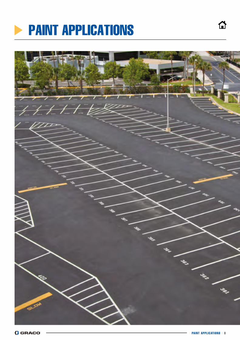
PAINT APPLICATIONS
PAINT APPL ICAT IONS I 9
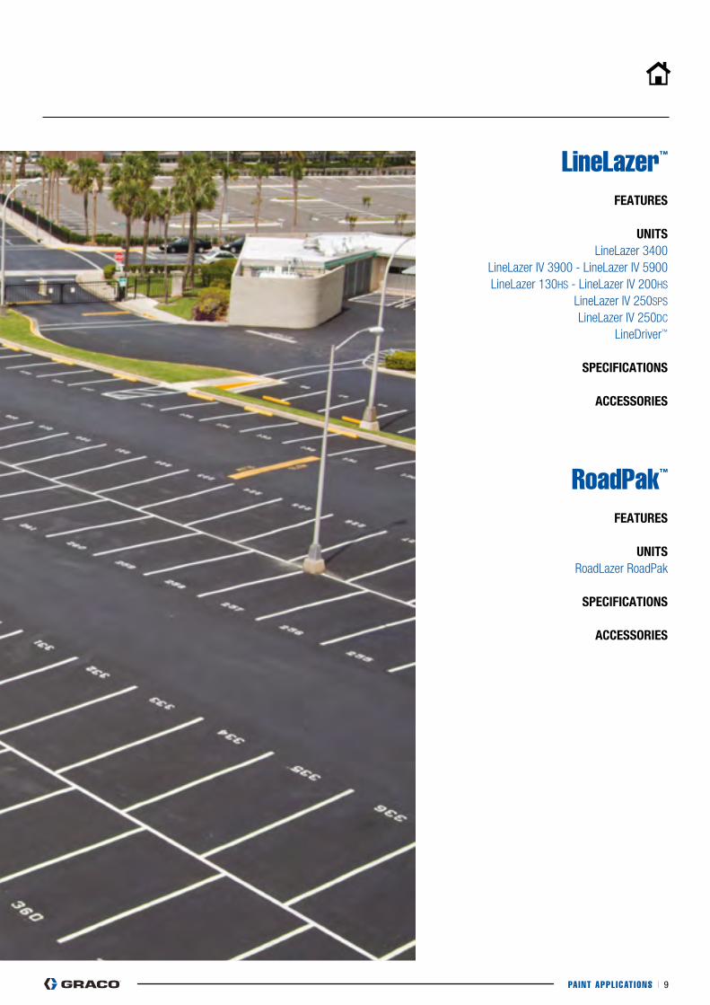
LineLazer™
feATURes
UniTs LineLazer 3400
LineLazer IV 3900 - LineLazer IV 5900 LineLazer 130HS - LineLazer IV 200HS
LineLazer IV 250SPS LineLazer IV 250DC
LineDriver™
sPeCifiCATiOns
ACCessORies
RoadPak™ feATURes
UniTsRoadLazer RoadPak
sPeCifiCATiOns
ACCessORies
PAINT APPL ICAT IONS I 10
pAINT AppLIcATIONS - LINELAZER - FEATURES
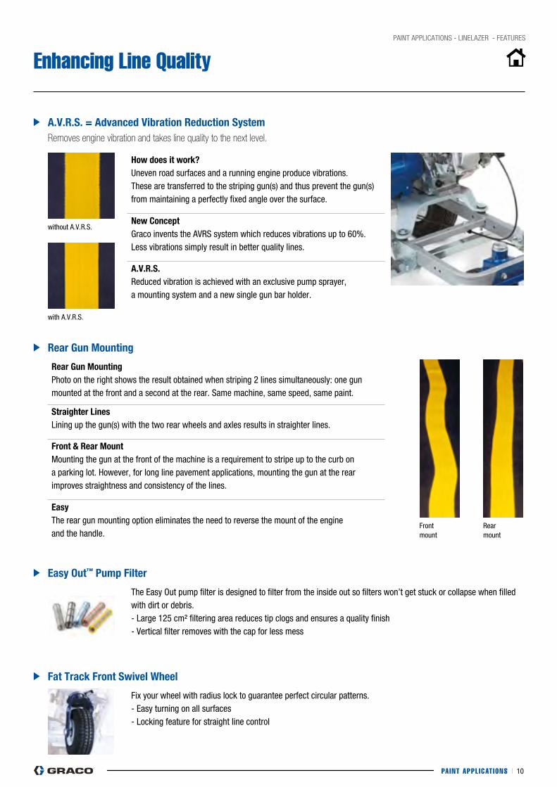
Enhancing Line Quality
A.V.R.s. = Advanced Vibration Reduction system
easy Out™ Pump filter
fat Track front swivel wheel
Rear Gun Mounting
Removes engine vibration and takes line quality to the next level.
without A.V.R.S.
with A.V.R.S.
Front mount
Rear mount
how does it work?Uneven road surfaces and a running engine produce vibrations. These are transferred to the striping gun(s) and thus prevent the gun(s) from maintaining a perfectly fixed angle over the surface.
new ConceptGraco invents the AVRS system which reduces vibrations up to 60%. Less vibrations simply result in better quality lines.
A.V.R.s.Reduced vibration is achieved with an exclusive pump sprayer, a mounting system and a new single gun bar holder.
Rear Gun Mountingphoto on the right shows the result obtained when striping 2 lines simultaneously: one gun mounted at the front and a second at the rear. Same machine, same speed, same paint.
straighter linesLining up the gun(s) with the two rear wheels and axles results in straighter lines.
front & Rear MountMounting the gun at the front of the machine is a requirement to stripe up to the curb on a parking lot. However, for long line pavement applications, mounting the gun at the rear improves straightness and consistency of the lines.
easyThe rear gun mounting option eliminates the need to reverse the mount of the engine and the handle.
The Easy Out pump filter is designed to filter from the inside out so filters won’t get stuck or collapse when filled with dirt or debris.- Large 125 cm² filtering area reduces tip clogs and ensures a quality finish- Vertical filter removes with the cap for less mess
Fix your wheel with radius lock to guarantee perfect circular patterns.- Easy turning on all surfaces- Locking feature for straight line control
PAINT APPL ICAT IONS I 11
pAINT AppLIcATIONS - LINELAZER - FEATURES
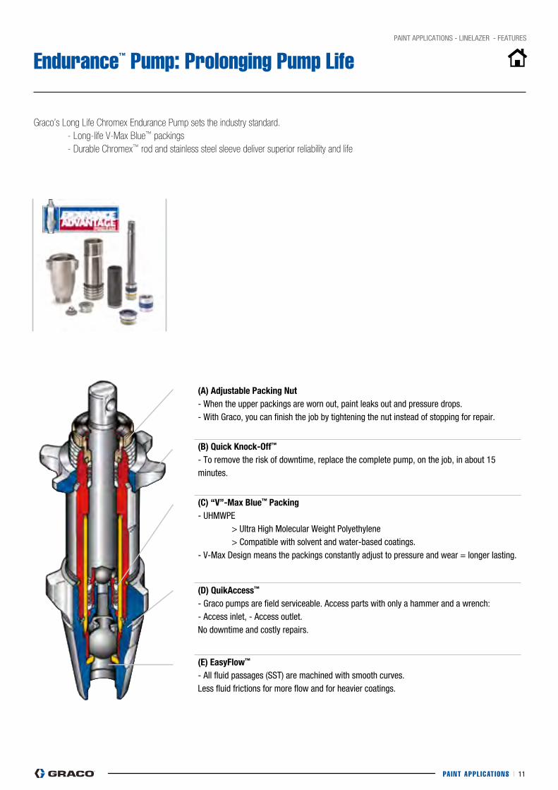
Endurance™ Pump: Prolonging Pump Life
Graco’s Long Life Chromex Endurance Pump sets the industry standard. - Long-life V-Max Blue™ packings - Durable Chromex™ rod and stainless steel sleeve deliver superior reliability and life
(A) Adjustable Packing nut- When the upper packings are worn out, paint leaks out and pressure drops.- With Graco, you can finish the job by tightening the nut instead of stopping for repair.
(B) Quick knock-Off™
- To remove the risk of downtime, replace the complete pump, on the job, in about 15 minutes.
(C) “V”-Max Blue™ Packing- UHMWpE > Ultra High Molecular Weight polyethylene > compatible with solvent and water-based coatings.- V-Max Design means the packings constantly adjust to pressure and wear = longer lasting.
(D) QuikAccess™
- Graco pumps are field serviceable. Access parts with only a hammer and a wrench: - Access inlet, - Access outlet. No downtime and costly repairs.
(e) easyflow™
- All fluid passages (SST) are machined with smooth curves.Less fluid frictions for more flow and for heavier coatings.
Digital Tracking System (DTS) / Système de contrôle numérique (DTS) / Sistema de control digital (DTS) / Digital Tracking System
311017E 27
8 Short press DTS button tomove to Job Film Build.
Note: Displays the averagewet film build (mils or microns)since the last reset.
9 Short press DTS buttonto move to job RESETdisplay.
10 Press and hold DTSbutton to reset jobdistance, job material andfilm build values to zero.
or
short press DTS buttonto return to Pressuredisplay.
8 Appuyer un coup bref sur lebouton DTS pour afficherl’épaisseur de la couche.
NB: Affichage de l’épaisseurde la couche humideappliquée (millièmes depouce ou microns) depuisla dernière remise à zéro.
9 Appuyer un coup bref surle bouton DTS pourafficher RESET.
10 Appuyer sur le boutonDTS et le maintenirenfoncé pour remettrela distance, la quantitéde produit et l’épaisseurde la couche à zéro.
ou
Appuyer un coup bref surle bouton DTS revenir àl’affichage de pression.
8 Pulse brevemente el botónDTS para avanzar hasta laAcumulación de Películade la tarea.
Nota: Visualiza el promediode acumulación de películahúmeda (milésimas o micras)desde la última reposición.
9 Pulse brevemente elbotón DTS para avanzarhasta la visualizaciónde REPOSICIÓN de latarea.
10 Pulse y mantengapulsado el botón DTSpara reponer a cero losvalores de la distancia, elmaterial y la acumulaciónde película de la tarea.
o
pulse brevemente elbotón DTS para regresara la visualización dePresión.
8 Prima o botão DTS paraavançar para a espessurada película do trabalho.
Nota: indica a espessuramédia da película húmida(mils ou mícrones) desde aúltima vez que foi restaurado.
9 Prima o botão DTS paraavançar para a indicaçãoRESET (restaurar) dotrabalho.
10 Prima continuamente obotão DTS para restaurara distância de trabalho,o material de trabalhoe valores de espessurada película do trabalhopara zero.
ou
prima o botão DTS pararegressar ao indicador depressão.
ti6441a ti6442a ti6443a ti6444a
Digital Tracking System (DTS) / Système de contrôle numérique (DTS) / Sistema de control digital (DTS) / Digital Tracking System
28 311017E
DTS Secondary Menu
1 Start engine, page 10.Pressure display appears.
2 Press and hold DTS button. At the same time, turn pumpswitch ON.Sprayer model momentarily displays.e.g. L5900 = LineLazer 5900
3 SERIAL NUM scrollsthrough display anda 3 to 5-digit serial numberdisplays.
Menu DTS secondaire
1 Démarrage du moteur,page 10. La pressions’affiche.
2 Appuyer sur le bouton DTS et le maintenir enfoncé. Dansle même temps, démarrer la pompe en appuyant sur ON.Le modèle de pulvérisateur s’affiche momentanément,p. ex., L5900 = LineLazer 5900.
3 SERIAL NUM apparaît surl’afficheur et un numérode série de 3 à 5 chiffress’affiche.
Menú secundario DTS
1 Ponga en marcha elmotor, página 10. Aparecela visualización depresión.
2 Pulse y mantenga pulsado el botón DTS. Al mismo tiempo,encienda la bomba ON.En la pantalla aparecerá momentáneamente el modelode pulverizador, p. ej., L5900 = LineLazer 5900
3 SERIAL NUM (NUMSERIE) aparece en lapantalla y se muestraun número de seriede 3 a 5 dígitos.
Menu Secundário do DTS
1 Coloque o motor emfuncionamento, página 10.É visualizado o indicadorde pressão.
2 Prima continuamente o botão DTS. Simultaneamente,ligue o interruptor da bomba ON.O modelo do equipamento surge momentaneamente,por ex.: L5900 = LineLazer 5900
3 A indicação SERIAL NUMsurge no visor, seguidade um número de sériede 3 a 5 dígitos.
OR
ti6602a ti6599a
ON
ti6524a
Digital Tracking System (DTS) / Système de contrôle numérique (DTS) / Sistema de control digital (DTS) / Digital Tracking System
311017E 25
Digital Tracking System (DTS) / Système de contrôle numérique (DTS) /Sistema de control digital (DTS) / Digital Tracking System (DTS)
Operation - Main Menu
Short press moves to nextdisplay.Long press changes units orresets data.
1 Start engine, pg 17.Sprayer Model displays briefly.e.g. L5900 = LineLazer 5900.Pressure display appears.Dashes appear when pressureis less than 200 psi (14 bar,1.4 MPa).
2 Short press DTS button tomove to Speed (miles perhour or kilometers perhour).
3 Short press DTS button tomove to rolling average FilmBuild (mils or microns).
Note: Displays the average wetfilm build over the last 20 ft (6 m)sprayed. The proper line width(LW) must be selected, step 7.
Fonctionnement – Menu principal
Appuyer un coup bref pourpasser à l’affichage suivant.Appuyer plus longtemps pourchanger les unités ouréinitialiser les données.
1 Démarrer le moteur,page 17.
Le modèle de pulvérisateurs’affiche brièvement : p. ex.L5900 = LineLazer 5900.L’afficheur de pression appa-raît. Des traits s’affichentquand la pression est inféri-eure à 200 psi (14 bars, 1,4MPa).
2 Appuyer un coup bref surle bouton DTS pourafficher la vitesse (milespar heure ou en kilomètrespar heure).
3 Appuyer un coup bref sur lebouton DTS pour afficherl’épaisseur moyenne de lacouche (millièmes de pouceou microns).
NB: Affichage de l’épaisseurmoyenne de la couche humideappliquée au cours des derniers20 ft (6 m). Il faut sélectionner lalargeur de ligne correcte (LW),point 7.
Operación – Menú principal
Pulsando brevemente el botónse avanza hasta la visual-ización siguiente.Pulsando más tiempo el botónse cambian las unidades o sereponen a cero los datos.
1 Ponga en marcha elmotor, pg 17.
Aparece brevemente el modelode pulverizador, p. ej. L5900 =LineLazer 5900. Aparece visu-alizada la presión. Cuando lapresión es menor de 200 psi(14 bar, 1,4 Mpa) apareceránrayas.
2 Pulse brevemente el botónDTS para avanzar hastaVelocidad (millas por horao kilómetros por hora).
3 Pulse brevemente el botónDTS para avanzar hasta elpromedio de Acumulaciónde Película en el rodillo(milésimas o micras).
Nota: Visualiza el promedio deacumulación de película húm-eda en los últimos 6 m (20 pies)de pulverización. Es necesarioseleccionar la anchura de líneacorrecta (LW), paso 7.
Funcionamento – Menu Principal
Basta premir levemente parapassar à indicação seguinte.Ao premir durante mais tempo,altera as unidades e restauraos dados.
1 Ligue o motor, pág. 17.Aparece momentaneamenteo modelo do equipamento depintura, por exemplo, L5900=LineLazer 5900. Aparece aindicação da pressão. Quandoa pressão é inferior a 200 psi(14 bar, 1,4 MPa) são visua-lizados traços.
2 Prima o botão DTS paraavançar para a velocidade(milhas por hora ouquilómetros por hora).
3 Prima o botão DTS paraavançar para apresentaçãoda espessura da película(mils ou mícrones).
Nota: apresenta a espessuramédia da película húmida nosúltimos 6 m (20 pés) pintados.Deve ser seleccionada a largurade linha correcta (LW), passo 7.
ti6433a OR
ti6602a
ti6435ati6436a
Digital Tracking System (DTS) / Système de contrôle numérique (DTS) / Sistema de control digital (DTS) / Digital Tracking System
311017E 29
4 Short press DTS buttonand date code scrollsthrough display.
5 Short press DTS buttonand part number scrollsthrough display. Partnumber scrolls repeatedly.
6 Short press DTS buttonand MEASure modedisplay appears.
7 MEASure mode displayappears. Use MEASuremode to measureunknown distances.
4 Appuyer brièvement sur lebouton DTS et le codedate défile sur l’écran.
5 Appuyer brièvement sur lebouton DTS et le numérode référence défile surl’écran. Le numéro deréférence défile de façonrépétée.
6 Appuyer brièvement sur lebouton DTS et le modeMEASure s’affiche.
7 Le mode MEASures’affiche. Utiliser le modeMEASure pour mesurerles distances inconnues.
4 Pulse brevemente elbotón DTS y la pantallase desplazará hasta elcódigo de la fecha.
5 Pulse brevemente elbotón DTS y y la pantallase desplazará hasta la ref.pieza. Esta informaciónaparece varias veces.
6 Pulse brevemente elbotón DTS y aparecerá ella pantalla del moto MEdir.
7 Aparece el modo MEdir.Utilice el modo MEdir paramedir las distanciasdesconocidas.
4 Prima o botão DTS, aindicação do código dadata surge no visor.
5 Prima o botão DTS, aindicação da referênciasurge no visor. Estainformação surgerepetidamente.
6 Prima o botão DTS,a indicação do modoMEASure (de medição)surge no visor.
7 O modo MEASure (demedição) surge no visor.Use o modo MEASure (demedição) para medir asdistâncias desconhecidas.
ti6525a ti6600a ti6601a
ti6447a
Digital Tracking System (DTS) / Système de contrôle numérique (DTS) / Sistema de control digital (DTS) / Digital Tracking System
311017E 25
Digital Tracking System (DTS) / Système de contrôle numérique (DTS) /Sistema de control digital (DTS) / Digital Tracking System (DTS)
Operation - Main Menu
Short press moves to nextdisplay.Long press changes units orresets data.
1 Start engine, pg 17.Sprayer Model displays briefly.e.g. L5900 = LineLazer 5900.Pressure display appears.Dashes appear when pressureis less than 200 psi (14 bar,1.4 MPa).
2 Short press DTS button tomove to Speed (miles perhour or kilometers perhour).
3 Short press DTS button tomove to rolling average FilmBuild (mils or microns).
Note: Displays the average wetfilm build over the last 20 ft (6 m)sprayed. The proper line width(LW) must be selected, step 7.
Fonctionnement – Menu principal
Appuyer un coup bref pourpasser à l’affichage suivant.Appuyer plus longtemps pourchanger les unités ouréinitialiser les données.
1 Démarrer le moteur,page 17.
Le modèle de pulvérisateurs’affiche brièvement : p. ex.L5900 = LineLazer 5900.L’afficheur de pression appa-raît. Des traits s’affichentquand la pression est inféri-eure à 200 psi (14 bars, 1,4MPa).
2 Appuyer un coup bref surle bouton DTS pourafficher la vitesse (milespar heure ou en kilomètrespar heure).
3 Appuyer un coup bref sur lebouton DTS pour afficherl’épaisseur moyenne de lacouche (millièmes de pouceou microns).
NB: Affichage de l’épaisseurmoyenne de la couche humideappliquée au cours des derniers20 ft (6 m). Il faut sélectionner lalargeur de ligne correcte (LW),point 7.
Operación – Menú principal
Pulsando brevemente el botónse avanza hasta la visual-ización siguiente.Pulsando más tiempo el botónse cambian las unidades o sereponen a cero los datos.
1 Ponga en marcha elmotor, pg 17.
Aparece brevemente el modelode pulverizador, p. ej. L5900 =LineLazer 5900. Aparece visu-alizada la presión. Cuando lapresión es menor de 200 psi(14 bar, 1,4 Mpa) apareceránrayas.
2 Pulse brevemente el botónDTS para avanzar hastaVelocidad (millas por horao kilómetros por hora).
3 Pulse brevemente el botónDTS para avanzar hasta elpromedio de Acumulaciónde Película en el rodillo(milésimas o micras).
Nota: Visualiza el promedio deacumulación de película húm-eda en los últimos 6 m (20 pies)de pulverización. Es necesarioseleccionar la anchura de líneacorrecta (LW), paso 7.
Funcionamento – Menu Principal
Basta premir levemente parapassar à indicação seguinte.Ao premir durante mais tempo,altera as unidades e restauraos dados.
1 Ligue o motor, pág. 17.Aparece momentaneamenteo modelo do equipamento depintura, por exemplo, L5900=LineLazer 5900. Aparece aindicação da pressão. Quandoa pressão é inferior a 200 psi(14 bar, 1,4 MPa) são visua-lizados traços.
2 Prima o botão DTS paraavançar para a velocidade(milhas por hora ouquilómetros por hora).
3 Prima o botão DTS paraavançar para apresentaçãoda espessura da película(mils ou mícrones).
Nota: apresenta a espessuramédia da película húmida nosúltimos 6 m (20 pés) pintados.Deve ser seleccionada a largurade linha correcta (LW), passo 7.
ti6433a OR
ti6602a
ti6435ati6436a
Digital Tracking System (DTS) / Système de contrôle numérique (DTS) / Sistema de control digital (DTS) / Digital Tracking System
26 311017E
4 Short press DTS button tomove to Job Distance (ft orm).
Note: Displays the linear linelength applied since the lastreset. See Reset screen,step 9.
5 Short press DTS button tomove to Job MaterialCounter.
Note: Displays materialsprayed (gallons or liters x 10)since the last reset.
6 Short press DTS button tomove to Line Width (LW)Selector.
Note: Displays the line widthused to calculate film build(in. or cm).
7 Press and hold DTSbutton to change LW. LWchanges from 2 - 12 in.(5 - 30 cm). Release DTSbutton when desired LWappears.
Note: If your distance readingis feet, LW is inches. If yourdistance reading is meters, LWis centimeters.
4 Appuyer un coup bref surle bouton DTS pour afficherla distance parcourue(ft ou m).
NB: Affichage de la longueurlinéaire de la ligne peintedepuis la dernière remiseà zéro. Voir l’écran deréinitialisation, point 9.
5 Appuyer un coup bref surle bouton DTS pourafficher la quantité deproduit consommée.
NB: Affichage de la quantité deproduit pulvérisé (gallons oulitres x 10) depuis la dernièreremise à zéro.
6 Appuyer un coup bref surle bouton DTS pourafficher le sélecteur delargeur de ligne (LW).
NB: Affichage de la largeurde ligne servant à calculerl’épaisseur de la couche(in. ou cm).
7 Appuyer sur le boutonDTS et le maintenirenfoncé pour changerla LW. La LW varie entre2 et 12 in. (5 – 30 cm).Relâcher le bouton DTSquand apparaît la LWdésirée.
NB: si l’affichage de distanceest en pieds, LW est enpouces. Si l’affichage dedistance est en mètres, LW esten centimètres.
4 Pulse brevemente el botónDTS para avanzar hastaDistancia de la tarea(pies o m).
Nota: Visualiza la longitud dela línea pintada desde la últimareposición a cero. Vea la pan-talla de Reposición, paso 9.
5 Pulse brevemente el botónDTS para avanzar hastaContador de materialde la tarea.
Nota: Visualiza el materialpulverizado (galoneso litros x 10) desde laúltima reposición.
6 Pulse brevemente el botónDTS para avanzar hasta elSelector de Anchura dela línea (LW).
Nota: Visualiza la anchura dela línea utilizada para calcularla acumulación de película(pulg. o cm).
7 Pulse y mantenga pulsadoel botón DTS paracambiar la LW. LWcambia desde 5 – 30 cm(2 – 12 pulg.). Suelte elbotón DTS cuandoaparezca la LW deseada.
Nota: Si la distancia está enpies, LW estará en pulgadas.Si la distancia está en metros,LW estará en centímetros.
4 Prima o botão DTS para irpara a distância de trabalho(ft ou m).
Nota: indica o comprimento dalinha linear aplicada, desde aúltima vez que foi restaurado.Consulte o ecrã de restaurar,passo 9.
5 Prima o botão DTS paraavançar para o contadordo material de trabalho.
Nota: mostra o volume deproduto aplicado (galões oulitros x 10), desde a última vezque foi restaurado.
6 Prima o botão DTS paraavançar para a selecçãoda largura de linha (LW).
Nota: indica a largura delinha utilizada para calculara espessura da película(pol. ou cm).
7 Prima continuamente obotão DTS para mudarde largura de linha (LW).A indicação LW muda de2 – 12 pol. (5 – 30 cm).Solte o botão DTS assimque aparecer a largurapretendida.
Nota: se a indicação de distân-cia for em pés, a largura delinha LW será em polegadas.Se a indicação de distância forem metros, a largura de linhaLW será em centímetros.
ti6437a ti6438a ti6439a ti6440a
Digital Tracking System (DTS) / Système de contrôle numérique (DTS) / Sistema de control digital (DTS) / Digital Tracking System
311017E 31
d Set pump switch OFF toexit MEASure mode.
9 Short press DTS button tomove from MEASuremode display to LIFEmaterial counter display.LIFEappearsmomentarily,then life time gallons(liters x 10) sprayed above800 psi (55 bar, 5.5 MPa).
10 Short press DTS buttonto move to Total MaterialCounter. TOTAL appearsmomentarily, then totalgallons (liters x 10)pumped at all pressures.
11 Short press DTS buttonto move to SPRAY(distance). MILES orKILOMETERS scrollsacross display, then totallength of lines applied.
d Mettre le bouton decommande de la pompesur OFF pour quitterle mode MEASure.
9 Appuyer un coup bref surle bouton DTS pour passerdu mode MEASure àl’affichage du compteurde produit LIFE. LIFEs’affiche un instant, puisc’est le tour des gallons(litres x 10) pulvérisés encontinu au-dessus de800 psi (55 bars, 5,5 MPa).
10 Appuyer un coup bref surle bouton DTS pourafficher la quantité totalede produit pulvérisé.TOTAL s’affiche uninstant, puis c’est le tourdes gallons (litres x 10)pompés à toutespressions.
11 Appuyer un coup brefsur le bouton DTSpour afficher SPRAY(distance). MILES ouKILOMETRES défilentsur l’écran, puis c’est lalongueur totale de lignepeinte.
d Coloque el interruptor dela bomba en OFF parasalir del modo MEdir.
9 Pulse brevemente el botónDTS para avanzar desdela visualización MEdirhasta la visualización delcontador de material LIFE.LIFE aparecerámomentáneamente,y después los galones(litros x 10) pulverizadospor encima de 800 psi(55 bar, 5,5 MPa).
10 Pulse brevemente elbotón DTS para avanzarhasta el Contador Totalde Material. TOTALaparecerámomentáneamente, ydespués el total degalones (litros x 10)bombeados a todas laspresiones.
11 Pulse brevemente elbotón DTS para avanzarhasta PULVERIZAR(distancia). Por la visua-lización se desplazaránMILES (MILLAS)o KILOMETERS (KILÓ-METROS), y después lalongitud total de laslíneas pintadas.
d Desligue a bomba nointerruptor OFF para sairdo modo MEASure (demedição).
9 Prima o botão DTSpara passar do modoMEASure (de medição)para a indicação docontador do materialLIFE. A indicação LIFEsurge momentanea-mente, seguida dovolume total até à data(litros x 10) aplicadoacima de 800 psi (55 bar,5,5 Mpa).
10 Prima o botão DTS parapassar para o contadordo material total. A indi-cação TOTAL aparecemomentaneamente,seguida do volume total(litros x 10) utilizadoa todas as pressões.
11 Prima o botão DTS parapassar para SPRAY(distância). A indicaçãoMILES (milhas) ouKILOMETERS(quilómetros) surge novisor, seguida do númerototal de linhas aplicado.
OFF
ti6477a
ti6452a ti6453a
ti6454a
Digital Tracking System (DTS) / Système de contrôle numérique (DTS) / Sistema de control digital (DTS) / Digital Tracking System
26 311017E
4 Short press DTS button tomove to Job Distance (ft orm).
Note: Displays the linear linelength applied since the lastreset. See Reset screen,step 9.
5 Short press DTS button tomove to Job MaterialCounter.
Note: Displays materialsprayed (gallons or liters x 10)since the last reset.
6 Short press DTS button tomove to Line Width (LW)Selector.
Note: Displays the line widthused to calculate film build(in. or cm).
7 Press and hold DTSbutton to change LW. LWchanges from 2 - 12 in.(5 - 30 cm). Release DTSbutton when desired LWappears.
Note: If your distance readingis feet, LW is inches. If yourdistance reading is meters, LWis centimeters.
4 Appuyer un coup bref surle bouton DTS pour afficherla distance parcourue(ft ou m).
NB: Affichage de la longueurlinéaire de la ligne peintedepuis la dernière remiseà zéro. Voir l’écran deréinitialisation, point 9.
5 Appuyer un coup bref surle bouton DTS pourafficher la quantité deproduit consommée.
NB: Affichage de la quantité deproduit pulvérisé (gallons oulitres x 10) depuis la dernièreremise à zéro.
6 Appuyer un coup bref surle bouton DTS pourafficher le sélecteur delargeur de ligne (LW).
NB: Affichage de la largeurde ligne servant à calculerl’épaisseur de la couche(in. ou cm).
7 Appuyer sur le boutonDTS et le maintenirenfoncé pour changerla LW. La LW varie entre2 et 12 in. (5 – 30 cm).Relâcher le bouton DTSquand apparaît la LWdésirée.
NB: si l’affichage de distanceest en pieds, LW est enpouces. Si l’affichage dedistance est en mètres, LW esten centimètres.
4 Pulse brevemente el botónDTS para avanzar hastaDistancia de la tarea(pies o m).
Nota: Visualiza la longitud dela línea pintada desde la últimareposición a cero. Vea la pan-talla de Reposición, paso 9.
5 Pulse brevemente el botónDTS para avanzar hastaContador de materialde la tarea.
Nota: Visualiza el materialpulverizado (galoneso litros x 10) desde laúltima reposición.
6 Pulse brevemente el botónDTS para avanzar hasta elSelector de Anchura dela línea (LW).
Nota: Visualiza la anchura dela línea utilizada para calcularla acumulación de película(pulg. o cm).
7 Pulse y mantenga pulsadoel botón DTS paracambiar la LW. LWcambia desde 5 – 30 cm(2 – 12 pulg.). Suelte elbotón DTS cuandoaparezca la LW deseada.
Nota: Si la distancia está enpies, LW estará en pulgadas.Si la distancia está en metros,LW estará en centímetros.
4 Prima o botão DTS para irpara a distância de trabalho(ft ou m).
Nota: indica o comprimento dalinha linear aplicada, desde aúltima vez que foi restaurado.Consulte o ecrã de restaurar,passo 9.
5 Prima o botão DTS paraavançar para o contadordo material de trabalho.
Nota: mostra o volume deproduto aplicado (galões oulitros x 10), desde a última vezque foi restaurado.
6 Prima o botão DTS paraavançar para a selecçãoda largura de linha (LW).
Nota: indica a largura delinha utilizada para calculara espessura da película(pol. ou cm).
7 Prima continuamente obotão DTS para mudarde largura de linha (LW).A indicação LW muda de2 – 12 pol. (5 – 30 cm).Solte o botão DTS assimque aparecer a largurapretendida.
Nota: se a indicação de distân-cia for em pés, a largura delinha LW será em polegadas.Se a indicação de distância forem metros, a largura de linhaLW será em centímetros.
ti6437a ti6438a ti6439a ti6440a
Digital Tracking System (DTS) / Système de contrôle numérique (DTS) / Sistema de control digital (DTS) / Digital Tracking System
32 311017E
12 Short press DTS button tomove to TOTAL (distance).MILES or KILOMETERSscrolls across display, thentotal distance traveled,with or without spraying.
13 Short press DTS button tomove to Engine Hourdisplay. ENGINE HOURSscrolls across display andthe clock symbol appears,then the lifetime enginerun hours.
14 Short press DTS button tomove to live Engine RPMdisplay.
15 Short press DTS buttonand LAST ERROR scrollsacross display followed bystored error message anderror code. Thisinformation cyclesrepeatedly until cleared.See manual 311020 forerror code explanations.
12 Appuyer un coup bref surle bouton DTS pourafficher TOTAL (distance).MILES ou KILOMETRESdéfilent sur l’écran, puisc’est la distance totaleparcourue qui s’affiche,avec ou sanspulvérisation.
13 Appuyer un coup bref surle bouton DTS pourafficher ENGINE HOURS.ENGINE HOURS défilesur l’écran et l’icône del’horloge apparaît, puisc’est le nombre d’heuresde marche du moteur.
14 Appuyer un coup bref surle bouton DTS pourafficher le régime moteurcontinu.
15 Appuyer brièvement sur lebouton DTS ; le messageLAST ERROR défile surl’afficheur suivi d’unmessage et code dedéfaut mémorisés. Cetteinformation est répétéejusqu’à son effacement.Voir le manuel 311020pour connaître lasignification du codede défaut.
12 Pulse brevemente el botónDTS para avanzar hastaTOTAL (distancia). Porla visualización sedesplazarán MILES(MILLAS) oKILOMETERS(KILÓMETROS), ydespués la distancia totalrecorrida, pulverizandoo sin pulverizar.
13 Pulse brevemente el botónDTS paraavanzar hasta lapantalla Horas del motor.ENGINE HOURS sedesplaza por la pantallay aparece el símbolo delreloj, y después las horasde funcionamiento delmotor.
14 Pulse brevemente el botónDTS para avanzar hastala visualización en vivode las RPM del Motor.
15 Pulse brevemente el botónDTS y en la pantallaaparecerá LAST ERROR(ÚLTIMO ERROR)seguido del mensajey el código de erroralmacenado. Estainformación aparecevarias veces hasta que seborra. Vea en el manual311020 las explicacionesde los códigos de error.
12 Prima o botão DTS paraavançar para TOTAL(distância). A indicaçãoMILES (milhas) ouKILOMETERS(quilómetros) surge novisor, seguida da distânciatotal percorrida, comaplicação ou não de tinta.
13 Prima o botão DTS paraavançar para o visorEngine Hours (horas domotor). ENGINE HOURS(horas do motor) passano visor e o símbolodo relógio aparece,seguido das horas defuncionamento do motor.
14 Prima o botão DTS paraavançar para a indicaçãodas rpm do motor.
15 Prima o botão DTS, aindicação LAST ERRORsurge no visor, seguida damensagem e do código deerro guardados. Estainformação surgerepetidamente até sereliminada. Consulteo manual 311020 parater conhecimento dasexplicações dos códigosde erro.
ti6455ati6456a
ti6457a
ti6528a
Digital Tracking System (DTS) / Système de contrôle numérique (DTS) / Sistema de control digital (DTS) / Digital Tracking System
311017E 27
8 Short press DTS button tomove to Job Film Build.
Note: Displays the averagewet film build (mils or microns)since the last reset.
9 Short press DTS buttonto move to job RESETdisplay.
10 Press and hold DTSbutton to reset jobdistance, job material andfilm build values to zero.
or
short press DTS buttonto return to Pressuredisplay.
8 Appuyer un coup bref sur lebouton DTS pour afficherl’épaisseur de la couche.
NB: Affichage de l’épaisseurde la couche humideappliquée (millièmes depouce ou microns) depuisla dernière remise à zéro.
9 Appuyer un coup bref surle bouton DTS pourafficher RESET.
10 Appuyer sur le boutonDTS et le maintenirenfoncé pour remettrela distance, la quantitéde produit et l’épaisseurde la couche à zéro.
ou
Appuyer un coup bref surle bouton DTS revenir àl’affichage de pression.
8 Pulse brevemente el botónDTS para avanzar hasta laAcumulación de Películade la tarea.
Nota: Visualiza el promediode acumulación de películahúmeda (milésimas o micras)desde la última reposición.
9 Pulse brevemente elbotón DTS para avanzarhasta la visualizaciónde REPOSICIÓN de latarea.
10 Pulse y mantengapulsado el botón DTSpara reponer a cero losvalores de la distancia, elmaterial y la acumulaciónde película de la tarea.
o
pulse brevemente elbotón DTS para regresara la visualización dePresión.
8 Prima o botão DTS paraavançar para a espessurada película do trabalho.
Nota: indica a espessuramédia da película húmida(mils ou mícrones) desde aúltima vez que foi restaurado.
9 Prima o botão DTS paraavançar para a indicaçãoRESET (restaurar) dotrabalho.
10 Prima continuamente obotão DTS para restaurara distância de trabalho,o material de trabalhoe valores de espessurada película do trabalhopara zero.
ou
prima o botão DTS pararegressar ao indicador depressão.
ti6441a ti6442a ti6443a ti6444a
Digital Tracking System (DTS) / Système de contrôle numérique (DTS) / Sistema de control digital (DTS) / Digital Tracking System
32 311017E
12 Short press DTS button tomove to TOTAL (distance).MILES or KILOMETERSscrolls across display, thentotal distance traveled,with or without spraying.
13 Short press DTS button tomove to Engine Hourdisplay. ENGINE HOURSscrolls across display andthe clock symbol appears,then the lifetime enginerun hours.
14 Short press DTS button tomove to live Engine RPMdisplay.
15 Short press DTS buttonand LAST ERROR scrollsacross display followed bystored error message anderror code. Thisinformation cyclesrepeatedly until cleared.See manual 311020 forerror code explanations.
12 Appuyer un coup bref surle bouton DTS pourafficher TOTAL (distance).MILES ou KILOMETRESdéfilent sur l’écran, puisc’est la distance totaleparcourue qui s’affiche,avec ou sanspulvérisation.
13 Appuyer un coup bref surle bouton DTS pourafficher ENGINE HOURS.ENGINE HOURS défilesur l’écran et l’icône del’horloge apparaît, puisc’est le nombre d’heuresde marche du moteur.
14 Appuyer un coup bref surle bouton DTS pourafficher le régime moteurcontinu.
15 Appuyer brièvement sur lebouton DTS ; le messageLAST ERROR défile surl’afficheur suivi d’unmessage et code dedéfaut mémorisés. Cetteinformation est répétéejusqu’à son effacement.Voir le manuel 311020pour connaître lasignification du codede défaut.
12 Pulse brevemente el botónDTS para avanzar hastaTOTAL (distancia). Porla visualización sedesplazarán MILES(MILLAS) oKILOMETERS(KILÓMETROS), ydespués la distancia totalrecorrida, pulverizandoo sin pulverizar.
13 Pulse brevemente el botónDTS paraavanzar hasta lapantalla Horas del motor.ENGINE HOURS sedesplaza por la pantallay aparece el símbolo delreloj, y después las horasde funcionamiento delmotor.
14 Pulse brevemente el botónDTS para avanzar hastala visualización en vivode las RPM del Motor.
15 Pulse brevemente el botónDTS y en la pantallaaparecerá LAST ERROR(ÚLTIMO ERROR)seguido del mensajey el código de erroralmacenado. Estainformación aparecevarias veces hasta que seborra. Vea en el manual311020 las explicacionesde los códigos de error.
12 Prima o botão DTS paraavançar para TOTAL(distância). A indicaçãoMILES (milhas) ouKILOMETERS(quilómetros) surge novisor, seguida da distânciatotal percorrida, comaplicação ou não de tinta.
13 Prima o botão DTS paraavançar para o visorEngine Hours (horas domotor). ENGINE HOURS(horas do motor) passano visor e o símbolodo relógio aparece,seguido das horas defuncionamento do motor.
14 Prima o botão DTS paraavançar para a indicaçãodas rpm do motor.
15 Prima o botão DTS, aindicação LAST ERRORsurge no visor, seguida damensagem e do código deerro guardados. Estainformação surgerepetidamente até sereliminada. Consulteo manual 311020 parater conhecimento dasexplicações dos códigosde erro.
ti6455ati6456a
ti6457a
ti6528a
Digital Tracking System (DTS) / Système de contrôle numérique (DTS) / Sistema de control digital (DTS) / Digital Tracking System
34 311017E
20 Press DTS again to return to CALibration display.
21 Short press DTS button. SOFTWARE REV scrolls across display followed by a 5-digit revision number.
22 Short press DTS button to return to step 1, Sprayer Model display.
23 Turn pump switch OFF at any time to exit Secondary Menu and return to Pressure display.
20 Appuyer à nouveau sur DTS pour revenir à l’écran affichant CALibration.
21 Appuyer brièvement sur le bouton DTS. SOFTWAREREV défile sur l’écran suivi par un numéro de révision à 5 chiffres.
22 Appuyer brièvement sur le bouton DTS pour passer au point 1, affichage de modèle de pulvérisateur.
23 ARRÊTER la pompe à n’importe quel moment pour quitter le Menu secondaire et revenir à l’affichage de pression.
20 Vuelva a pulsar el botón DTS para regresar a la pantalla CALibración.
21 Pulse brevemente el botón DTS. SOFTWARE REV se desplaza por la pantalla seguido de un número de revisión de 5 dígitos.
22 Pulse brevemente el botón DTS para regresar al paso 1, aparece el Modelo de pulverizador.
23 Apague el interruptor de la bomba OFF para salir en cualquier momento del Menú secundario y regresar a la visualización de la presión.
20 Prima novamente DTS para voltar ao visor CALibration.
21 Prima o botão DTS. A indicação SOFTWAREREV (revisão do software) surge no visor, seguida de um número de revisão de 5 dígitos.
22 Prima o botão DTS para voltar ao passo 1, para a indicação do modelo do equipamento.
23 Desligue a bomba no interruptor OFF em qualquer altura para sair do Menu Secundário e regressar ao indicador de pressão.
ti6462a
ti6463a
ti6608a
ti6464a
OFF
ti6477a
Digital Tracking System (DTS) / Système de contrôle numérique (DTS) / Sistema de control digital (DTS) / Digital Tracking System
311017E 27
8 Short press DTS button tomove to Job Film Build.
Note: Displays the averagewet film build (mils or microns)since the last reset.
9 Short press DTS buttonto move to job RESETdisplay.
10 Press and hold DTSbutton to reset jobdistance, job material andfilm build values to zero.
or
short press DTS buttonto return to Pressuredisplay.
8 Appuyer un coup bref sur lebouton DTS pour afficherl’épaisseur de la couche.
NB: Affichage de l’épaisseurde la couche humideappliquée (millièmes depouce ou microns) depuisla dernière remise à zéro.
9 Appuyer un coup bref surle bouton DTS pourafficher RESET.
10 Appuyer sur le boutonDTS et le maintenirenfoncé pour remettrela distance, la quantitéde produit et l’épaisseurde la couche à zéro.
ou
Appuyer un coup bref surle bouton DTS revenir àl’affichage de pression.
8 Pulse brevemente el botónDTS para avanzar hasta laAcumulación de Películade la tarea.
Nota: Visualiza el promediode acumulación de películahúmeda (milésimas o micras)desde la última reposición.
9 Pulse brevemente elbotón DTS para avanzarhasta la visualizaciónde REPOSICIÓN de latarea.
10 Pulse y mantengapulsado el botón DTSpara reponer a cero losvalores de la distancia, elmaterial y la acumulaciónde película de la tarea.
o
pulse brevemente elbotón DTS para regresara la visualización dePresión.
8 Prima o botão DTS paraavançar para a espessurada película do trabalho.
Nota: indica a espessuramédia da película húmida(mils ou mícrones) desde aúltima vez que foi restaurado.
9 Prima o botão DTS paraavançar para a indicaçãoRESET (restaurar) dotrabalho.
10 Prima continuamente obotão DTS para restaurara distância de trabalho,o material de trabalhoe valores de espessurada película do trabalhopara zero.
ou
prima o botão DTS pararegressar ao indicador depressão.
ti6441a ti6442a ti6443a ti6444a
Digital Tracking System (DTS) / Système de contrôle numérique (DTS) / Sistema de control digital (DTS) / Digital Tracking System
32 311017E
12 Short press DTS button tomove to TOTAL (distance).MILES or KILOMETERSscrolls across display, thentotal distance traveled,with or without spraying.
13 Short press DTS button tomove to Engine Hourdisplay. ENGINE HOURSscrolls across display andthe clock symbol appears,then the lifetime enginerun hours.
14 Short press DTS button tomove to live Engine RPMdisplay.
15 Short press DTS buttonand LAST ERROR scrollsacross display followed bystored error message anderror code. Thisinformation cyclesrepeatedly until cleared.See manual 311020 forerror code explanations.
12 Appuyer un coup bref surle bouton DTS pourafficher TOTAL (distance).MILES ou KILOMETRESdéfilent sur l’écran, puisc’est la distance totaleparcourue qui s’affiche,avec ou sanspulvérisation.
13 Appuyer un coup bref surle bouton DTS pourafficher ENGINE HOURS.ENGINE HOURS défilesur l’écran et l’icône del’horloge apparaît, puisc’est le nombre d’heuresde marche du moteur.
14 Appuyer un coup bref surle bouton DTS pourafficher le régime moteurcontinu.
15 Appuyer brièvement sur lebouton DTS ; le messageLAST ERROR défile surl’afficheur suivi d’unmessage et code dedéfaut mémorisés. Cetteinformation est répétéejusqu’à son effacement.Voir le manuel 311020pour connaître lasignification du codede défaut.
12 Pulse brevemente el botónDTS para avanzar hastaTOTAL (distancia). Porla visualización sedesplazarán MILES(MILLAS) oKILOMETERS(KILÓMETROS), ydespués la distancia totalrecorrida, pulverizandoo sin pulverizar.
13 Pulse brevemente el botónDTS paraavanzar hasta lapantalla Horas del motor.ENGINE HOURS sedesplaza por la pantallay aparece el símbolo delreloj, y después las horasde funcionamiento delmotor.
14 Pulse brevemente el botónDTS para avanzar hastala visualización en vivode las RPM del Motor.
15 Pulse brevemente el botónDTS y en la pantallaaparecerá LAST ERROR(ÚLTIMO ERROR)seguido del mensajey el código de erroralmacenado. Estainformación aparecevarias veces hasta que seborra. Vea en el manual311020 las explicacionesde los códigos de error.
12 Prima o botão DTS paraavançar para TOTAL(distância). A indicaçãoMILES (milhas) ouKILOMETERS(quilómetros) surge novisor, seguida da distânciatotal percorrida, comaplicação ou não de tinta.
13 Prima o botão DTS paraavançar para o visorEngine Hours (horas domotor). ENGINE HOURS(horas do motor) passano visor e o símbolodo relógio aparece,seguido das horas defuncionamento do motor.
14 Prima o botão DTS paraavançar para a indicaçãodas rpm do motor.
15 Prima o botão DTS, aindicação LAST ERRORsurge no visor, seguida damensagem e do código deerro guardados. Estainformação surgerepetidamente até sereliminada. Consulteo manual 311020 parater conhecimento dasexplicações dos códigosde erro.
ti6455ati6456a
ti6457a
ti6528a
Digital Tracking System (DTS) / Système de contrôle numérique (DTS) / Sistema de control digital (DTS) / Digital Tracking System
34 311017E
20 Press DTS again to return to CALibration display.
21 Short press DTS button. SOFTWARE REV scrolls across display followed by a 5-digit revision number.
22 Short press DTS button to return to step 1, Sprayer Model display.
23 Turn pump switch OFF at any time to exit Secondary Menu and return to Pressure display.
20 Appuyer à nouveau sur DTS pour revenir à l’écran affichant CALibration.
21 Appuyer brièvement sur le bouton DTS. SOFTWAREREV défile sur l’écran suivi par un numéro de révision à 5 chiffres.
22 Appuyer brièvement sur le bouton DTS pour passer au point 1, affichage de modèle de pulvérisateur.
23 ARRÊTER la pompe à n’importe quel moment pour quitter le Menu secondaire et revenir à l’affichage de pression.
20 Vuelva a pulsar el botón DTS para regresar a la pantalla CALibración.
21 Pulse brevemente el botón DTS. SOFTWARE REV se desplaza por la pantalla seguido de un número de revisión de 5 dígitos.
22 Pulse brevemente el botón DTS para regresar al paso 1, aparece el Modelo de pulverizador.
23 Apague el interruptor de la bomba OFF para salir en cualquier momento del Menú secundario y regresar a la visualización de la presión.
20 Prima novamente DTS para voltar ao visor CALibration.
21 Prima o botão DTS. A indicação SOFTWAREREV (revisão do software) surge no visor, seguida de um número de revisão de 5 dígitos.
22 Prima o botão DTS para voltar ao passo 1, para a indicação do modelo do equipamento.
23 Desligue a bomba no interruptor OFF em qualquer altura para sair do Menu Secundário e regressar ao indicador de pressão.
ti6462a
ti6463a
ti6608a
ti6464a
OFF
ti6477a
PAINT APPL ICAT IONS I 12
pAINT AppLIcATIONS - LINELAZER - FEATURES
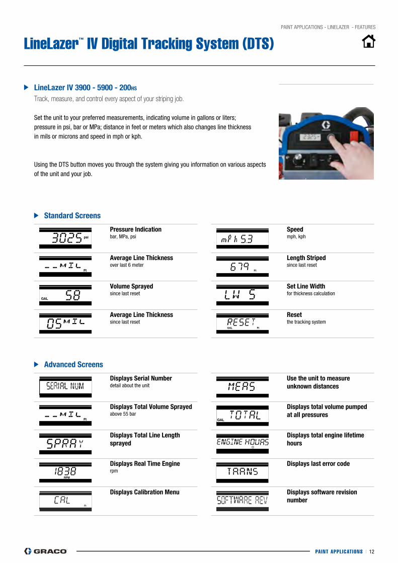
LineLazer™ IV Digital Tracking System (DTS)
linelazer iV 3900 - 5900 - 200hs
Track, measure, and control every aspect of your striping job.
Set the unit to your preferred measurements, indicating volume in gallons or liters; pressure in psi, bar or Mpa; distance in feet or meters which also changes line thickness in mils or microns and speed in mph or kph.
Using the DTS button moves you through the system giving you information on various aspects of the unit and your job.
Pressure indication bar, Mpa, psi
Average line Thickness over last 6 meter
Volume sprayed since last reset
Average line Thickness since last reset
speed mph, kph
length striped since last reset
set line width for thickness calculation
Reset the tracking system
Displays serial number detail about the unit
Displays Total Volume sprayed above 55 bar
Displays Total line length sprayed
Displays Real Time engine rpm
Displays Calibration Menu
Use the unit to measure unknown distances
Displays total volume pumped at all pressures
Displays total engine lifetime hours
Displays last error code
Displays software revision number
standard screens
Advanced screens
PAINT APPL ICAT IONS I 13
pAINT AppLIcATIONS - LINELAZER - FEATURES
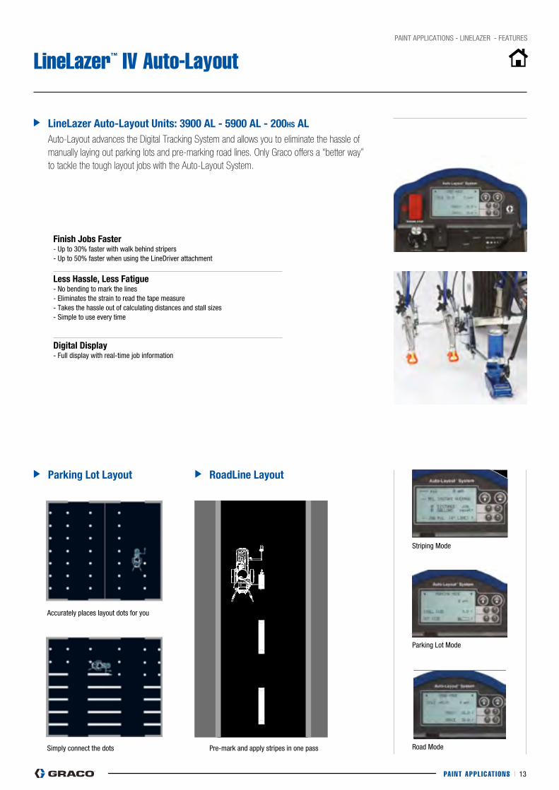
LineLazer™ IV Auto-Layout
Road Mode
parking Lot Mode
Striping Mode
linelazer Auto-layout Units: 3900 Al - 5900 Al - 200hs AlAuto-Layout advances the Digital Tracking System and allows you to eliminate the hassle of manually laying out parking lots and pre-marking road lines. Only Graco offers a “better way” to tackle the tough layout jobs with the Auto-Layout System.
finish Jobs faster - Up to 30% faster with walk behind stripers- Up to 50% faster when using the LineDriver attachment
less hassle, less fatigue- No bending to mark the lines- Eliminates the strain to read the tape measure- Takes the hassle out of calculating distances and stall sizes- Simple to use every time
Digital Display- Full display with real-time job information
Parking lot layout Roadline layout
Simply connect the dots
Accurately places layout dots for you
pre-mark and apply stripes in one pass
Quick Guide - LineLazer IV Auto Layout System
312307E 3
Quick Guide - LineLazer IV Auto Layout System
ti8387b_front
Quick Guide - LineLazer IV Auto Layout System
312307E 3
Quick Guide - LineLazer IV Auto Layout System
ti8387b_front
Quick Guide - LineLazer IV Auto Layout System
312307E 3
Quick Guide - LineLazer IV Auto Layout System
ti8387b_front
Quick Guide - LineLazer IV Auto Layout System
312307E 3
Quick Guide - LineLazer IV Auto Layout System
ti8387b_front
Quick Guide - LineLazer IV Auto Layout System
312307E 3
Quick Guide - LineLazer IV Auto Layout System
ti8387b_front
Quick Guide - LineLazer IV Auto Layout System
312307E 3
Quick Guide - LineLazer IV Auto Layout System
ti8387b_front
Quick Guide - LineLazer IV Auto Layout System
312307E 3
Quick Guide - LineLazer IV Auto Layout System
ti8387b_front
Quick Guide - LineLazer IV Auto Layout System
312307E 3
Quick Guide - LineLazer IV Auto Layout System
ti8387b_front
Quick Guide - LineLazer IV Auto Layout System
312307E 3
Quick Guide - LineLazer IV Auto Layout System
ti8387b_front
Quick Guide - LineLazer IV Auto Layout System
312307E 3
Quick Guide - LineLazer IV Auto Layout System
ti8387b_front
PAINT APPL ICAT IONS I 14
pAINT AppLIcATIONS - LINELAZER - FEATURES
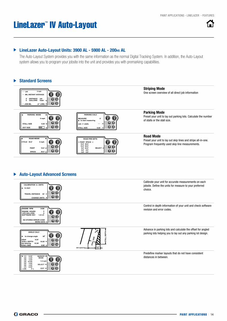
LineLazer™ IV Auto-Layout
linelazer Auto-layout Units: 3900 Al - 5900 Al - 200hs AlThe Auto-Layout System provides you with the same information as the normal Digital Tracking System. In addition, the Auto-Layout system allows you to program your jobsite into the unit and provides you with premarking capabilities.
striping Mode One screen overview of all direct job information
Parking Mode preset your unit to lay out parking lots. calculate the number of stalls or the stall size.
Road Mode preset your unit to lay out skip lines and stripe all-in-one. program frequently used skip line measurements.
calibrate your unit for accurate measurements on each jobsite. Define the units for measure to your preferred choice.
control in depth information of your unit and check software revision and error codes.
Advance in parking lots and calculate the offset for angled parking lots helping you to lay out any parking lot design.
predefine marker layouts that do not have consistent distances in between.
standard screens
Auto-layout Advanced screens

Smart Control Overview
3A2090A Operation 21
Smart Control Overview
Quick Guide
Smart Control Operation
333388B Operation 23
Main MenusUse MENU buttons to scroll thorough the four main menus.
Striping Mode
See Striping Mode, page 26 for features.
Measure Mode
See Measure Mode, page 27 for features.
Layout Mode
See Layout Mode, page 28 for features.
Setup/Information
See Setup/Information, page 31 for features.
World Sym
bol Key
333388B Operation
35
World Sym
bol Key
LL250 GLOBAL SYMBOL KEY MENU SCREENS
STRIPING MODE MEASURE MODE LAYOUT MODE SETTINGS/DATA
MANUAL ORAUTOMATIC MODE
PRESSURE
GALLONS/LITERS
LINE THICKNESS
PAINT LENGTH
SPACE LENGTH
LINE WIDTH
SWITCH 1
SWITCH 2
SWITCH 3
EXIT
PRESS TO START/STOP
HOLD TO SPRAY A DOT
STALL CALCULATOR
ANGLE CALCULATOR
STALL WIDTH
DOT SIZE SELECTOR
CALIBRATE
UNITS
INFORMATION& LIFE DATA
LANGUAGE SELECTION
MARKER LAYOUT MODE
SPECIFIC GRAVITY
ENGINE HOURS
TOTAL DISTANCE
TOTAL GALLONS
SOFTWARE REV
ERROR CODES
BEEP MODE
CONTRAST
DIAGNOSTICS
TIME AND DATE
LOW SPEED SHUTOFF
I/O
........
ENG SPA FRE GLOBAL
÷x+-
÷x+-
1 2 3 4 5 6 7 8 9 10
X'
X'
A
ti23824a
PAINT APPL ICAT IONS I 15
pAINT AppLIcATIONS - LINELAZER - FEATURES
LineLazer™ IV Auto-Layout
linelazer iV 250sPs and 250DC
The LineLazer IV 250SPS and LineLazer IV 250DC provide you with ultimate programmability in striping and layout modes. Equipped with programmable guns, both LineLazer IV 250 units allow you to spray skip lines automatically without the hassle of spray cans.
world symbols linelazer iV 250DC
LineLazer IV 250Dc is equipped with a World Symbols feature which can be used in any language. Use symbols to visualize the Digital Tracking System of your unit.
linelazer iV 250sPs
- Same programming options as Auto-Layout- Built-in Auto-Layout over spray guns- Two automatic gun control solenoids- Automatic safety shut-off in case of sudden brake
linelazer iV 250DC
- Same programming options as LineLazer IV 250SpS
- Three automatic gun control solenoids- Displays information on both pumps- control the auto shut-off speed- Advanced unit diagnostics- World symbols as language
linelazer iV 250 screens and features
sTRiPinG MODe MeAsURe MODe lAYOUT MODe seTTinGs/DATA
MANUAL OR AUTOMATIC MODE
PRESSURE
PRESS TO START/STOP STALL CALCULATOR CALIBRATE
UNITS
INFORMATION & LIFETIME
LANGUAGE SELECTION
MARKER LAYOUT MODE
SPECIFIC GRAVITY
ENGINE HOURS
TOTAL DISTANCE
TOTAL GALLONS
SOFTWARE REV
ERROR CODES
BEEP MODES
CONTRAST
DIAGNOSTICS
TIME AND DATE
LOW SPEED SHUTOFF
ANGLE CALCULATOR
STALL WIDTH
DOT SIZE SELECTOR
HOLD TO SPRAY A DOT
GALLONS/LITERS
LINE THICKNESS
PAINT LENGTH
SPACE LENGTH
LINE WIDTH
SWITCH 1
SWITCH 2
SWITCH 3
EXIT
PAINT APPL ICAT IONS I 16
pAINT AppLIcATIONS - LINELAZER - FEATURES
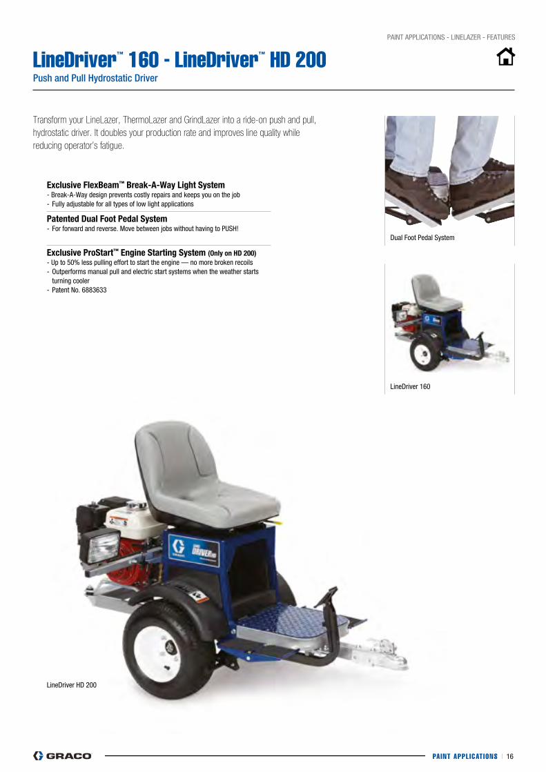
LineDriver™ 160 - LineDriver™ HD 200 Push and Pull Hydrostatic Driver
LineDriver HD 200
Transform your LineLazer, ThermoLazer and GrindLazer into a ride-on push and pull, hydrostatic driver. It doubles your production rate and improves line quality while reducing operator’s fatigue.
LineDriver 160
Dual Foot pedal System
exclusive flexBeam™ Break-A-way light system - Break-A-Way design prevents costly repairs and keeps you on the job- Fully adjustable for all types of low light applications
Patented Dual foot Pedal system- For forward and reverse. Move between jobs without having to pUSH!
exclusive Prostart™ engine starting system (Only on hD 200)- Up to 50% less pulling effort to start the engine — no more broken recoils- Outperforms manual pull and electric start systems when the weather starts turning cooler- patent No. 6883633

PAINT APPL ICAT IONS I 17
PAINT APPL ICAT IONS I 18
pAINT AppLIcATIONS - LINELAZER - UNITS
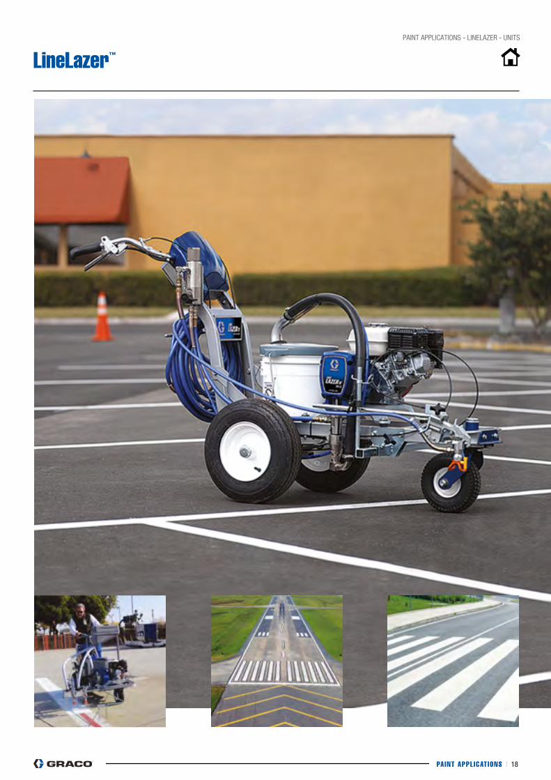
LineLazer™
PAINT APPL ICAT IONS I 19
pAINT AppLIcATIONS - LINELAZER - UNITS
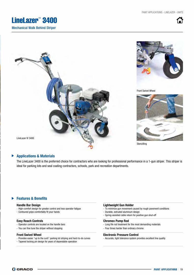
LineLazer™ 3400Mechanical Walk Behind Striper
features & Benefits
Applications & Materials
LineLazer IV 3400
The LineLazer 3400 is the preferred choice for contractors who are looking for professional performance in a 1-gun striper. This striper is ideal for parking lots and seal coating contractors, schools, park and recreation departments.
handle Bar Design - High-comfort design for greater control and less operator fatigue- contoured grips comfortably fit your hands
lightweight Gun holder - To minimize gun movement caused by rough pavement conditions- Durable, extruded aluminum design- Spring-assisted cable return for positive gun shut-off
easy Reach Controls- Operator controls are located on the handle bars
- you can fine tune the striper without stopping
Chromex Pump Rod- Long life rod treatment for the most demanding materials
- Four times harder than ordinary chrome
front swivel wheel- provides easier “up to the curb” parking lot striping and hard-to-do curves- Tapered locking pin design for years of dependable operation
electronic Pressure Control- Accurate, tight tolerance system provides excellent line quality
Stencilling
Front Swivel Wheel
PAINT APPL ICAT IONS I 20
pAINT AppLIcATIONS - LINELAZER - UNITS
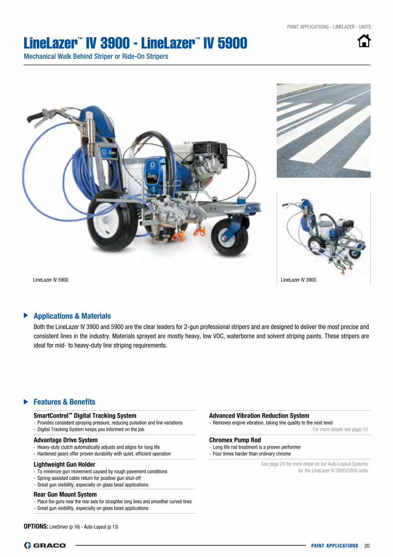
LineLazer™ IV 3900 - LineLazer™ IV 5900 Mechanical Walk Behind Striper or Ride-On Stripers
smartControl™ Digital Tracking system- provides consistent spraying pressure, reducing pulsation and line variations- Digital Tracking System keeps you informed on the job
Advanced Vibration Reduction system- Removes engine vibration, taking line quality to the next level
For more details see page 10
Advantage Drive system- Heavy-duty clutch automatically adjusts and aligns for long life- Hardened gears offer proven durability with quiet, efficient operation
Chromex Pump Rod- Long life rod treatment is a proven performer- Four times harder than ordinary chrome
lightweight Gun holder- To minimize gun movement caused by rough pavement conditions- Spring-assisted cable return for positive gun shut-off- Great gun visibility, especially on glass bead applications
See page 24 for more detail on our Auto-Layout Systems for the LineLazer IV 3900/5900 units
Rear Gun Mount system- place the guns near the rear axle for straighter long lines and smoother curved lines- Great gun visibility, especially on glass bead applications
features & Benefits
OPTiOns: LineDriver (p 16) - Auto-Layout (p 13)
Applications & Materials
LineLazer IV 5900 LineLazer IV 3900
Both the LineLazer IV 3900 and 5900 are the clear leaders for 2-gun professional stripers and are designed to deliver the most precise and consistent lines in the industry. Materials sprayed are mostly heavy, low VOc, waterborne and solvent striping paints. These stripers are ideal for mid- to heavy-duty line striping requirements.
PAINT APPL ICAT IONS I 21
pAINT AppLIcATIONS - LINELAZER - UNITS
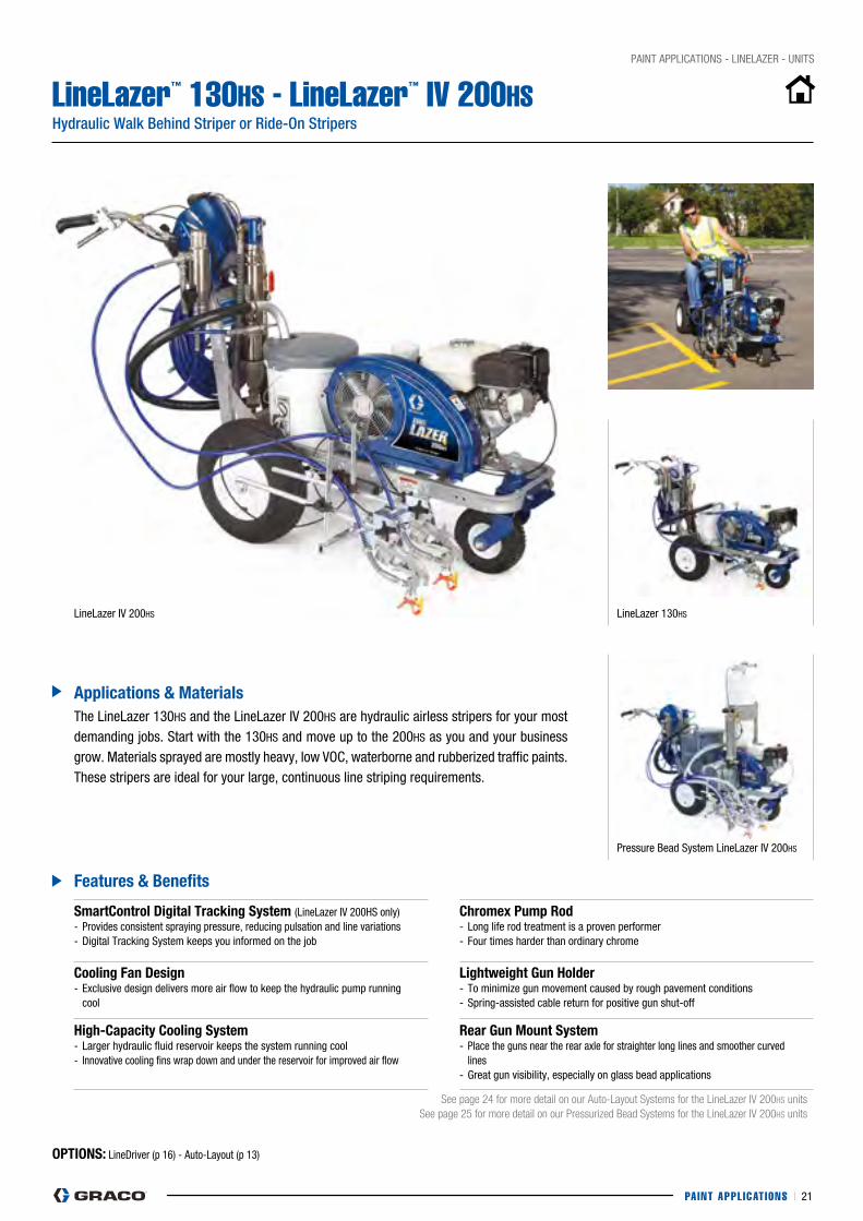
LineLazer™ 130HS - LineLazer™ IV 200HSHydraulic Walk Behind Striper or Ride-On Stripers
OPTiOns: LineDriver (p 16) - Auto-Layout (p 13)
smartControl Digital Tracking system (LineLazer IV 200HS only) - provides consistent spraying pressure, reducing pulsation and line variations- Digital Tracking System keeps you informed on the job
Chromex Pump Rod - Long life rod treatment is a proven performer- Four times harder than ordinary chrome
Cooling fan Design- Exclusive design delivers more air flow to keep the hydraulic pump running cool
lightweight Gun holder- To minimize gun movement caused by rough pavement conditions- Spring-assisted cable return for positive gun shut-off
high-Capacity Cooling system- Larger hydraulic fluid reservoir keeps the system running cool- Innovative cooling fins wrap down and under the reservoir for improved air flow
Rear Gun Mount system- place the guns near the rear axle for straighter long lines and smoother curved lines- Great gun visibility, especially on glass bead applications
See page 24 for more detail on our Auto-Layout Systems for the LineLazer IV 200HS units See page 25 for more detail on our Pressurized Bead Systems for the LineLazer IV 200HS units
features & Benefits
Applications & Materials
LineLazer IV 200HS LineLazer 130HS
The LineLazer 130HS and the LineLazer IV 200HS are hydraulic airless stripers for your most demanding jobs. Start with the 130HS and move up to the 200HS as you and your business grow. Materials sprayed are mostly heavy, low VOc, waterborne and rubberized traffic paints. These stripers are ideal for your large, continuous line striping requirements.
pressure Bead System LineLazer IV 200HS
PAINT APPL ICAT IONS I 22
pAINT AppLIcATIONS - LINELAZER - UNITS
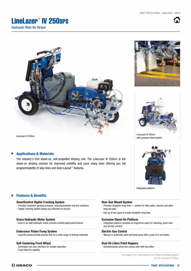
LineLazer™ IV 250SPS Hydraulic Ride-On Striper
smartControl Digital Tracking system- provides consistent spraying pressure, reducing pulsation and line variations- Digital Tracking System keeps you informed on the job
Rear Gun Mount system - provides straighter long lines — perfect for bike paths, airports and other long line jobs
- Use up to four guns to create straighter long lines
Graco hydraulic Motor system - Graco’s no-stall hydraulic motor provides uninterrupted performance
exclusive stand-On Platform - Integrated platform provides an ergonomic place for standing, great view and all-day comfort.
endurance Piston Pump system- Long life pumps provide precise flow for a wide range of striping materials
electric Gun Control- Manual or automatic paint and bead guns with a push of a red button
self-Centering front wheel- Eliminates one user interface for simpler operation- Foam filled for stability
Dual 55-liters Paint hoppers- Simultaneously spray two colours and refill less often
See page 25 for more detail on our Pressurized Bead Systems for the LineLazer IV 250SPS
features & Benefits
Applications & Materials
LineLazer IV 250SpSLineLazer IV 250SpS with pressure bead system
The industry’s first stand-on, self-propelled striping unit. The LineLazer IV 250SpS is the stand-on striping solution for improved visibility and razor sharp lines offering you full programmability of skip lines and Auto-Layout™ features.
Integrated platform
PAINT APPL ICAT IONS I 23
pAINT AppLIcATIONS - LINELAZER - UNITS
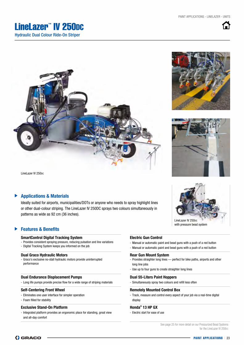
LineLazer™ IV 250DCHydraulic Dual Colour Ride-On Striper
features & Benefits
Applications & MaterialsIdeally suited for airports, municipalities/DOTs or anyone who needs to spray highlight lines or other dual-colour striping. The LineLazer IV 250Dc sprays two colours simultaneously in patterns as wide as 92 cm (36 inches).
smartControl Digital Tracking system- provides consistent spraying pressure, reducing pulsation and line variations- Digital Tracking System keeps you informed on the job
electric Gun Control- Manual or automatic paint and bead guns with a push of a red button
- Manual or automatic paint and bead guns with a push of a red button
Dual Graco hydraulic Motors - Graco’s exclusive no-stall hydraulic motors provide uninterrupted performance
Rear Gun Mount system - provides straighter long lines — perfect for bike paths, airports and other
long line jobs
- Use up to four guns to create straighter long lines
Dual endurance Displacement Pumps- Long life pumps provide precise flow for a wide range of striping materials
Dual 55-liters Paint hoppers - Simultaneously spray two colours and refill less often
self-Centering front wheel- Eliminates one user interface for simpler operation
- Foam filled for stability
Remotely Mounted Control Box- Track, measure and control every aspect of your job via a real-time digital
display
exclusive stand-On Platform- Integrated platform provides an ergonomic place for standing, great view
and all-day comfort
honda® 13 hP Gx- Electric start for ease of use
See page 25 for more detail on our Pressurized Bead Systems for the LineLazer IV 250DC
LineLazer IV 250Dc
with pressure bead system
LineLazer IV 250Dc
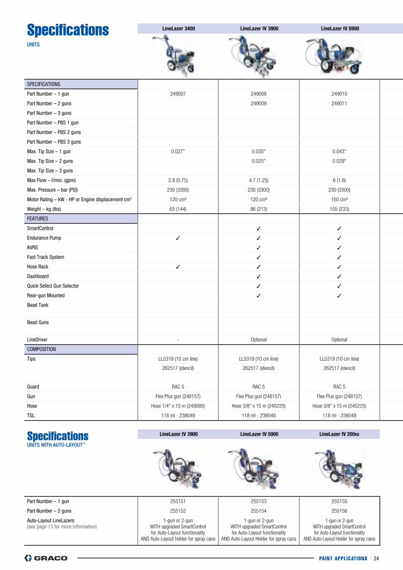
PAINT APPL ICAT IONS I 24
SpecificationsUNITS
linelazer 3400 linelazer iV 3900 linelazer iV 5900 linelazer 130hs linelazer iV 200hs linelazer iV 250sPs linelazer iV 250DC
SpEcIFIcATIONS
part Number – 1 gun 249007 249008 249010 257780 249012 24K961
part Number – 2 guns 249009 249011 249013 24K962 24U242
part Number – 3 guns 24U810
part Number – pBS 1 gun 16V594 16V471
part Number – pBS 2 guns 16V595 16V474 24U243
part Number – pBS 3 guns 24U820
Max. Tip Size – 1 gun 0.027" 0.035" 0.043" 0.037" 0.045" 0.055" 0.055"
Max. Tip Size – 2 guns 0.025" 0.029" 0.033" 0.039" 0.039"
Max. Tip Size – 3 guns 0.031"
Max Flow – l/min. (gpm) 2.8 (0.75) 4.7 (1.25) 6 (1.6) 4.9 (1.3) 7.5 (2.0) 9.5 (2.5) 9.5 (2.5)
Max. pressure – bar (pSI) 230 (3300) 230 (3300) 230 (3300) 230 (3300) 230 (3300) 230 (3300) 230 (3300)
Motor Rating – kW - Hp or Engine displacement cm3 120 cm³ 120 cm³ 160 cm³ 118 cm³ 200 cm3 390 cm³ - Electric Start 390 cm³ - Electric Start
Weight – kg (lbs) 65 (144) 96 (213) 105 (233) 108 (240) 110 (242) 284 (627) 340 (752)
FEATURES
Smartcontrol ✓ ✓ ✓ ✓ ✓
Endurance pump ✓ ✓ ✓ Hydraulic Hydraulic Hydraulic Hydraulic
AVRS ✓ ✓ ✓ ✓ ✓ ✓
Fast Track System ✓ ✓ ✓
Hose Rack ✓ ✓ ✓ ✓
Dashboard ✓ ✓ ✓ ✓ ✓ ✓
Quick Select Gun Selector ✓ ✓ ✓ Automatic Guns Automatic Guns
Rear-gun Mounted ✓ ✓ ✓ ✓ ✓
Bead Tank 1 bead tank (16V594 & 16V595)
1 bead tank (16V471 & 16V474)
2 bead tanks (only for 24U243 & 24U820)
Bead Guns 16V594 (1 bead gun) 16V595 (2 bead guns)
16V471 (1 bead gun) 16V474 (2 bead guns)
24U243 (2 paint+bead guns) 24U820 (3 paint+bead guns)
LineDriver - Optional Optional Optional Optional Self Propelled System Self Propelled System
cOMpOSITION
Tips LL5319 (10 cm line) LL5319 (10 cm line) LL5319 (10 cm line) LL5319 (10 cm line) LL5319 (10 cm line) LL5319 (10 cm line) LL5319 (10 cm line)
262517 (stencil) 262517 (stencil) 262517 (stencil) 262517 (stencil) 262517 (stencil) 262421 (stencil) 262421 (stencil)
262111 (Auto-Layout) 262111 (Auto-Layout)
Guard RAC 5 RAC 5 RAC 5 RAC 5 RAC 5 RAC 5
Gun Flex Plus gun (248157) Flex Plus gun (248157) Flex Plus gun (248157) Flex Plus gun (248157) Flex Plus gun (248157) Flex Plus gun (248157)
Hose Hose 1/4" x 15 m (249080) Hose 3/8" x 15 m (245225) Hose 3/8" x 15 m (245225) Hose 3/8" x 15 m (245225) Hose 3/8" x 15 m (245225) Hose 3/8" x 15 m (245225) Hose 3/8" x 15 m (245225)
TSL 118 ml - 238049 118 ml - 238049 118 ml - 238049 118 ml - 238049 118 ml - 238049 118 ml - 238049
Specifications UNITS WITH AUTO-LAyOUT™
linelazer iV 3900 linelazer iV 5900 linelazer iV 200hs
part Number – 1 gun 255151 255153 255155
part Number – 2 guns 255152 255154 255156
Auto-Layout LineLazers(see page 13 for more information)
1-gun or 2-gun WITH upgraded SmartControl for Auto-Layout functionality
AND Auto-Layout holder for spray cans
1-gun or 2-gunWITH upgraded SmartControl for Auto-Layout functionality
AND Auto-Layout Holder for spray cans
1-gun or 2-gun WITH upgraded SmartControl for Auto-Layout functionality
AND Auto-Layout Holder for spray cans
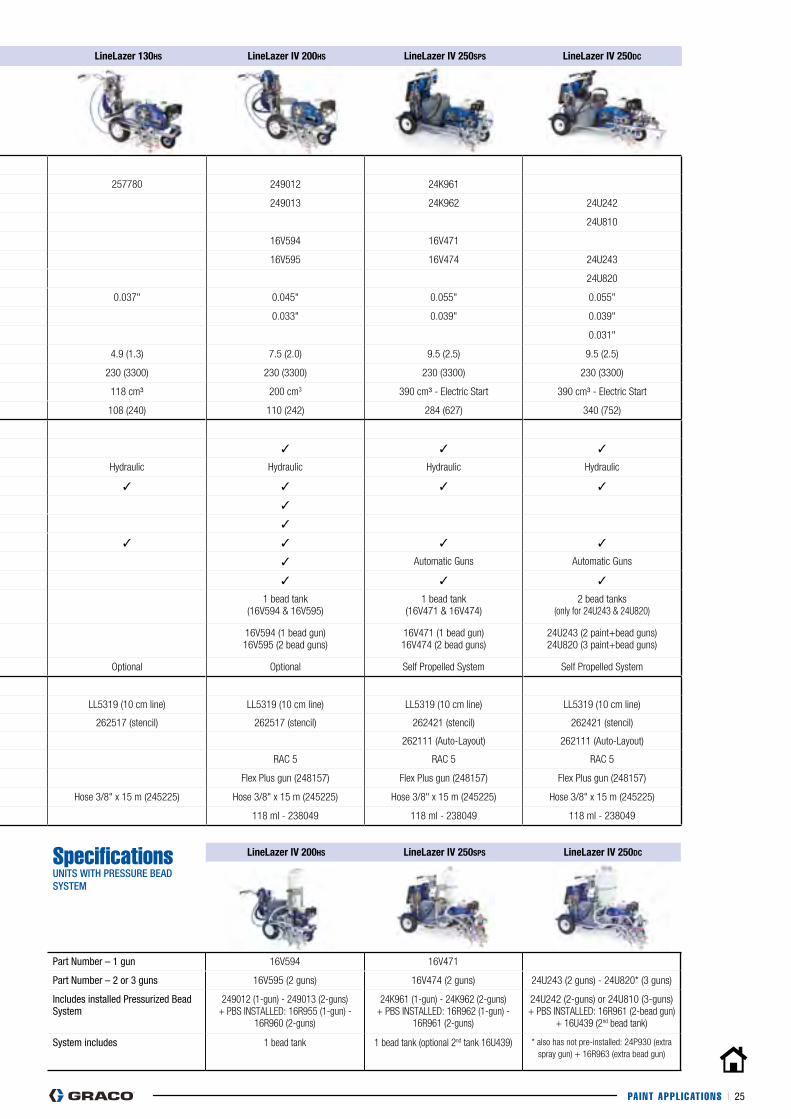
PAINT APPL ICAT IONS I 25
SpecificationsUNITS
linelazer 3400 linelazer iV 3900 linelazer iV 5900 linelazer 130hs linelazer iV 200hs linelazer iV 250sPs linelazer iV 250DC
SpEcIFIcATIONS
part Number – 1 gun 249007 249008 249010 257780 249012 24K961
part Number – 2 guns 249009 249011 249013 24K962 24U242
part Number – 3 guns 24U810
part Number – pBS 1 gun 16V594 16V471
part Number – pBS 2 guns 16V595 16V474 24U243
part Number – pBS 3 guns 24U820
Max. Tip Size – 1 gun 0.027" 0.035" 0.043" 0.037" 0.045" 0.055" 0.055"
Max. Tip Size – 2 guns 0.025" 0.029" 0.033" 0.039" 0.039"
Max. Tip Size – 3 guns 0.031"
Max Flow – l/min. (gpm) 2.8 (0.75) 4.7 (1.25) 6 (1.6) 4.9 (1.3) 7.5 (2.0) 9.5 (2.5) 9.5 (2.5)
Max. pressure – bar (pSI) 230 (3300) 230 (3300) 230 (3300) 230 (3300) 230 (3300) 230 (3300) 230 (3300)
Motor Rating – kW - Hp or Engine displacement cm3 120 cm³ 120 cm³ 160 cm³ 118 cm³ 200 cm3 390 cm³ - Electric Start 390 cm³ - Electric Start
Weight – kg (lbs) 65 (144) 96 (213) 105 (233) 108 (240) 110 (242) 284 (627) 340 (752)
FEATURES
Smartcontrol ✓ ✓ ✓ ✓ ✓
Endurance pump ✓ ✓ ✓ Hydraulic Hydraulic Hydraulic Hydraulic
AVRS ✓ ✓ ✓ ✓ ✓ ✓
Fast Track System ✓ ✓ ✓
Hose Rack ✓ ✓ ✓ ✓
Dashboard ✓ ✓ ✓ ✓ ✓ ✓
Quick Select Gun Selector ✓ ✓ ✓ Automatic Guns Automatic Guns
Rear-gun Mounted ✓ ✓ ✓ ✓ ✓
Bead Tank 1 bead tank (16V594 & 16V595)
1 bead tank (16V471 & 16V474)
2 bead tanks (only for 24U243 & 24U820)
Bead Guns 16V594 (1 bead gun) 16V595 (2 bead guns)
16V471 (1 bead gun) 16V474 (2 bead guns)
24U243 (2 paint+bead guns) 24U820 (3 paint+bead guns)
LineDriver - Optional Optional Optional Optional Self Propelled System Self Propelled System
cOMpOSITION
Tips LL5319 (10 cm line) LL5319 (10 cm line) LL5319 (10 cm line) LL5319 (10 cm line) LL5319 (10 cm line) LL5319 (10 cm line) LL5319 (10 cm line)
262517 (stencil) 262517 (stencil) 262517 (stencil) 262517 (stencil) 262517 (stencil) 262421 (stencil) 262421 (stencil)
262111 (Auto-Layout) 262111 (Auto-Layout)
Guard RAC 5 RAC 5 RAC 5 RAC 5 RAC 5 RAC 5
Gun Flex Plus gun (248157) Flex Plus gun (248157) Flex Plus gun (248157) Flex Plus gun (248157) Flex Plus gun (248157) Flex Plus gun (248157)
Hose Hose 1/4" x 15 m (249080) Hose 3/8" x 15 m (245225) Hose 3/8" x 15 m (245225) Hose 3/8" x 15 m (245225) Hose 3/8" x 15 m (245225) Hose 3/8" x 15 m (245225) Hose 3/8" x 15 m (245225)
TSL 118 ml - 238049 118 ml - 238049 118 ml - 238049 118 ml - 238049 118 ml - 238049 118 ml - 238049
Specifications UNITS WITH PRESSURE BEAD SySTEM
linelazer iV 200hs linelazer iV 250sPs linelazer iV 250DC
part Number – 1 gun 16V594 16V471
part Number – 2 or 3 guns 16V595 (2 guns) 16V474 (2 guns) 24U243 (2 guns) - 24U820* (3 guns)
Includes installed pressurized Bead System
249012 (1-gun) - 249013 (2-guns)+ PBS INSTALLED: 16R955 (1-gun) -
16R960 (2-guns)
24K961 (1-gun) - 24K962 (2-guns)+ PBS INSTALLED: 16R962 (1-gun) -
16R961 (2-guns)
24U242 (2-guns) or 24U810 (3-guns)+ PBS INSTALLED: 16R961 (2-bead gun)
+ 16U439 (2nd bead tank)
System includes 1 bead tank 1 bead tank (optional 2nd tank 16U439) * also has not pre-installed: 24P930 (extra spray gun) + 16R963 (extra bead gun)

PAINT APPL ICAT IONS I 26
PART nUMBeR
DesCRiPTiOn
GUN AND HOSE KITS
248157 FLEXpLUS STRIpING GUN WITH LL5319 TIp
245225 LINELAZER HOSE WITH E-NIcKEL FITTINGS. 3/8" X 15 M (230 BAR)
245798 LINELAZER HOSE WITH E-NIcKEL FITTINGS. 1/4" X 1.8 M (230 BAR) (2nd gun hose)
249080 cOUpLED HOSE, 1/4 X 15M (LINELAZER 3400 only)
124884 LINELAZER HOSE WITH E-NIcKEL FITTINGS, 3/8 IN X 6M, 3300 pSI (LINELAZER IV 250SpS only)
191239 LINELAZER HOSE WITH E-NIcKEL FITTINGS, 3/8 IN X 3.6M, 3300 pSI (LINELAZER IV 250Dc only)
pAINT GUN KITS
287553 cOMpLETE KIT FOR ADDING 2ND GUN (LINELAZER III 3900/5900 – LINELAZER IV)
241284 2ND GUN KIT (for LINELAZER II only)
24M679 cOMpLETE KIT FOR ADDING 2ND GUN (LINELAZER IV 250)
24p930 cOMpLETE KIT FOR ADDING 3RD OR 4TH GUN (LINELAZER IV 250)
BEAD GUN KITS
16R963 cOMpLETE KIT FOR ADDING BEAD GUN TO pBS UNITS
STENcIL KITS
24G778 pAINT GUN STENcIL KIT Includes: (1) paint Gun and 1/4 in x 15m Hose and Mounting Brackets
238957 HAND BEAD STENcIL KIT (Use with the EZ Bead pressurized Dispensing System Only) Includes: (1) Bead Gun, (2) 3/4 in x 7,5m clear Hoses, .234 in /.35 degree Tip, 30 cm Extension Tube and Mounting Brackets
pAINT AppLIcATIONS - LINELAZER - AccESSORIES
LineLazer™ Accessories
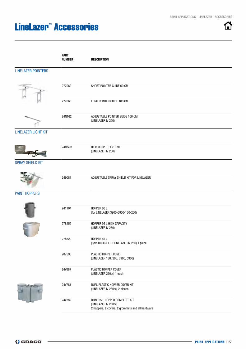
PAINT APPL ICAT IONS I 27
PART nUMBeR
DesCRiPTiOn
LINELAZER pOINTERS
277062 SHORT pOINTER GUIDE 60 cM
277063 LONG pOINTER GUIDE 100 cM
24N162 ADjUSTABLE pOINTER GUIDE 100 cM, (LINELAZER IV 250)
LINELAZER LIGHT KIT
24M598 HIGH OUTpUT LIGHT KIT (LINELAZER IV 250)
SpRAy SHIELD KIT
249081 ADjUSTABLE SpRAy SHIELD KIT FOR LINELAZER
pAINT HOppERS
241104 HOppER 60 L (for LINELAZER 3900-5900-130-200)
278452 HOppER 95 L HIGH cApAcITy (LINELAZER IV 250)
278720 HOppER 55 L (Split DESIGN FOR LINELAZER IV 250) 1 piece
287590 pLASTIc HOppER cOVER (LINELAZER 130, 200, 3900, 5900)
24V687 pLASTIc HOppER cOVER (LINELAZER 250Dc) 1 each
24V781 DUAL pLASTIc HOppER cOVER KIT (LINELAZER IV 250Dc) 2 pieces
24V782 DUAL 55 L HOppER cOMpLETE KIT (LINELAZER IV 250Dc) 2 hoppers, 2 covers, 2 grommets and all hardware
pAINT AppLIcATIONS - LINELAZER - AccESSORIES
LineLazer™ Accessories
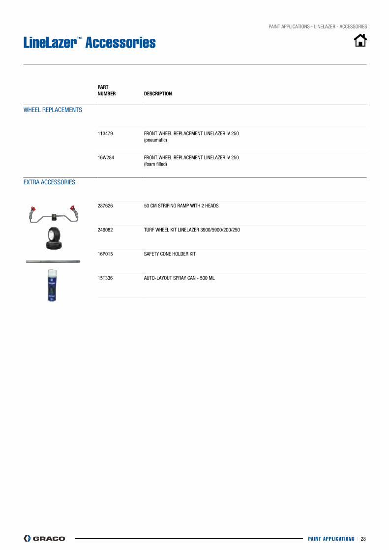
PAINT APPL ICAT IONS I 28
pAINT AppLIcATIONS - LINELAZER - AccESSORIES
LineLazer™ Accessories
PART nUMBeR
DesCRiPTiOn
WHEEL REpLAcEMENTS
113479 FRONT WHEEL REpLAcEMENT LINELAZER IV 250 (pneumatic)
16W284 FRONT WHEEL REpLAcEMENT LINELAZER IV 250 (foam filled)
EXTRA AccESSORIES
287626 50 cM STRIpING RAMp WITH 2 HEADS
249082 TURF WHEEL KIT LINELAZER 3900/5900/200/250
16p015 SAFETy cONE HOLDER KIT
15T336 AUTO-LAyOUT SpRAy cAN - 500 ML
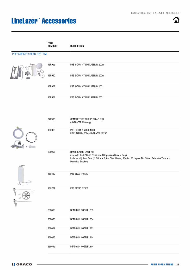
PAINT APPL ICAT IONS I 29
pAINT AppLIcATIONS - LINELAZER - AccESSORIES
LineLazer™ Accessories
PART nUMBeR
DesCRiPTiOn
pRESSURIZED BEAD SySTEM
16R955 pBS 1-GUN KIT LINELAZER IV 200HS
16R960 pBS 2-GUN KIT LINELAZER IV 200HS
16R962 pBS 1-GUN KIT LINELAZER IV 250
16R961 pBS 2-GUN KIT LINELAZER IV 250
24p930 cOMpLETE KIT FOR 3RD OR 4TH GUN (LINELAZER 250 only)
16R963 pBS EXTRA BEAD GUN KIT LINELAZER IV 200HS/LINELAZER IV 250
238957 HAND BEAD STENcIL KIT (Use with the EZ Bead pressurized Dispensing System Only) Includes: (1) Bead Gun, (2) 3/4 in x 7,5m clear Hoses, .234 in /.35 degree Tip, 30 cm Extension Tube and Mounting Brackets
16U439 pBS BEAD TANK KIT
16U272 pBS RETRO FIT KIT
238663 BEAD GUN NOZZLE .203
238666 BEAD GUN NOZZLE .234
238664 BEAD GUN NOZZLE .281
238665 BEAD GUN NOZZLE .344
238665 BEAD GUN NOZZLE .344
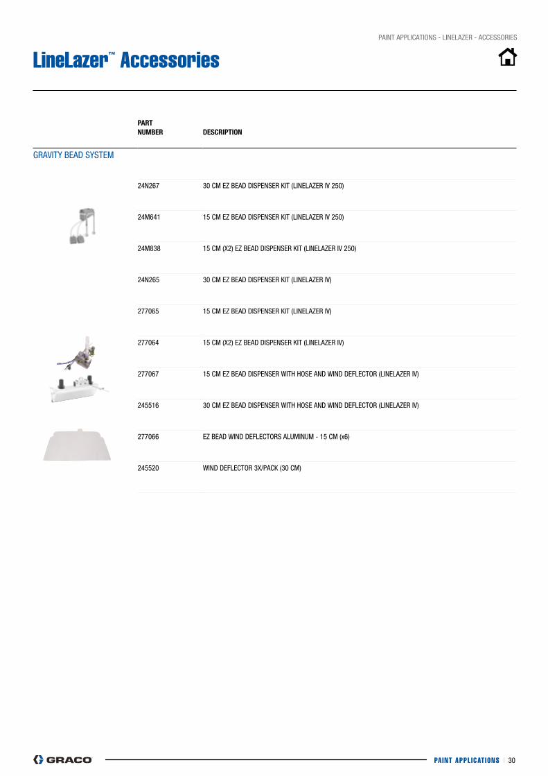
PAINT APPL ICAT IONS I 30
pAINT AppLIcATIONS - LINELAZER - AccESSORIES
LineLazer™ Accessories
PART nUMBeR
DesCRiPTiOn
GRAVITy BEAD SySTEM
24N267 30 cM EZ BEAD DISpENSER KIT (LINELAZER IV 250)
24M641 15 cM EZ BEAD DISpENSER KIT (LINELAZER IV 250)
24M838 15 cM (X2) EZ BEAD DISpENSER KIT (LINELAZER IV 250)
24N265 30 cM EZ BEAD DISpENSER KIT (LINELAZER IV)
277065 15 cM EZ BEAD DISpENSER KIT (LINELAZER IV)
277064 15 cM (X2) EZ BEAD DISpENSER KIT (LINELAZER IV)
277067 15 cM EZ BEAD DISpENSER WITH HOSE AND WIND DEFLEcTOR (LINELAZER IV)
245516 30 cM EZ BEAD DISpENSER WITH HOSE AND WIND DEFLEcTOR (LINELAZER IV)
277066 EZ BEAD WIND DEFLEcTORS ALUMINUM - 15 cM (x6)
245520 WIND DEFLEcTOR 3X/pAcK (30 cM)
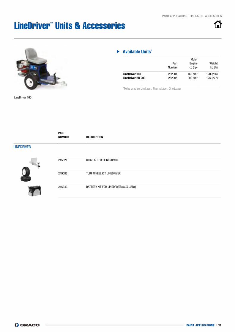
PAINT APPL ICAT IONS I 31
pAINT AppLIcATIONS - LINELAZER - AccESSORIES
LineDriver™ Units & Accessories
LineDriver 160
PART nUMBeR
DesCRiPTiOn
LINEDRIVER
245321 HITcH KIT FOR LINEDRIVER
249083 TURF WHEEL KIT LINEDRIVER
245343 BATTERy KIT FOR LINEDRIVER (AUXILIARy)
Available Units*
part Number
Motor Engine cc (hp)
Weight kg (lb)
lineDriver 160lineDriver hD 200
262004262005
160 cm³200 cm³
120 (266)125 (277)
*To be used on LineLazer, ThermoLazer, GrindLazer

PAINT APPL ICAT IONS I 32
pAINT AppLIcATIONS - ROADpAK - FEATURES
RoadLazer RoadPak™ Hydraulic Walk Behind Striper or Ride-On Stripers
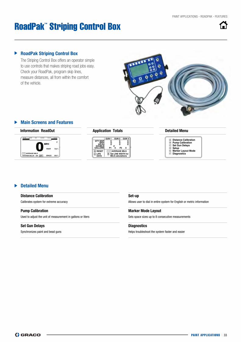
Operation
3A1215C 5
Menus
Information Readout (S tartup/Main Menu)
Measuring Counter: Resets every time HOLD/RESET is activated.
The First Menu is used to set the paint length of a skip line and the frequency of that length.
1. Set paint length with adjacent arrows.2. Set cycle length with adjacent arrows.
AVERAGE MILS (MIC): Continuously displays line thick-ness based on accumulated distance and material usage from application totals in next menu.NOTE: To store current skip line, press and hold any Menu Control button (A - F) to assign the skip line to that button.
Application Totals
The Counter Menu measures the actual paint distance in feet (meters) from each paint gun. This menu also mea-sures the gallons (liters) of paint sprayed by guns 1, 2, and 3. The average rate is calculated in the row at the bottom of the screen based on line width.*
NOTE: The DOUBLE row indicates when Gun 1 and Gun 2 are on at the same time.
Audible Speed Indicator ™
The Speed Alarm Menu allows you to set the speed range (mph) that you would like to work within. The controller will beep rapidly when you exceed the upper limit, and slowly when you fall below the lower limit.
See System Delay Example , page 9.
ti16373a
Switch (J) must be in HOLD position
ti16374a
ti16375a
Operation
6 3A1215C
Distance Calibration
The Distance Calibration Menu is used to calibrate the system against a measured distance (see Distance Calibration Procedure , page 9).1. Use adjacent arrows to enter the length of the mea-
sured course.
2. Press at the beginning of the measured course.
3. Press at the end of the measured course.
NOTE: Distance accuracy is based on calibration. Use a good quality measuring tape.
Pump Calibration
The Pump Calibration Menu is used to adjust the unit of measurement for accurate material usage in gallons or liters.
1. Press to toggle between units for display mea-surements.
2. Use adjacent arrows to change pump cycles per unit volume (RPS 2900 preset value is 14.9, Road-Lazer Tow Behind is 37. Value may need adjusting due to viscosity of material)
Set Gun Delays
The Set Gun Delays Menu is used to synchronize paint and bead guns in inches (cm). Incrementing value is based on the resolution of the distance sensor.
NOTE: In the event of no distance travel sensing the guns will default to a 1 second delay.
NOTE: Follow on-screen instructions.
1. Press to switch between Bead Gun and Paint Gun.
2. Use adjacent arrows to change ON/OFF Delay Distance.
ti16376a
ti16381a
ti16377a
PAINT APPL ICAT IONS I 33
pAINT AppLIcATIONS - ROADpAK - FEATURES
RoadPak™ Striping Control Box
RoadPak striping Control BoxThe Striping Control Box offers an operator simple to use controls that makes striping road jobs easy. Check your RoadPak, program skip lines, measure distances, all from within the comfort of the vehicle.
information ReadOut
Main screens and features
Detailed Menu
Distance Calibrationcalibrates system for extreme accuracy
set-upAllows user to dial in entire system for English or metric information
Pump CalibrationUsed to adjust the unit of measurement in gallons or liters
Marker Mode layout Sets space sizes up to 8 consecutive measurements
set Gun DelaysSynchronizes paint and bead guns
Diagnostics Helps troubleshoot the system faster and easier
Application Totals Detailed Menu
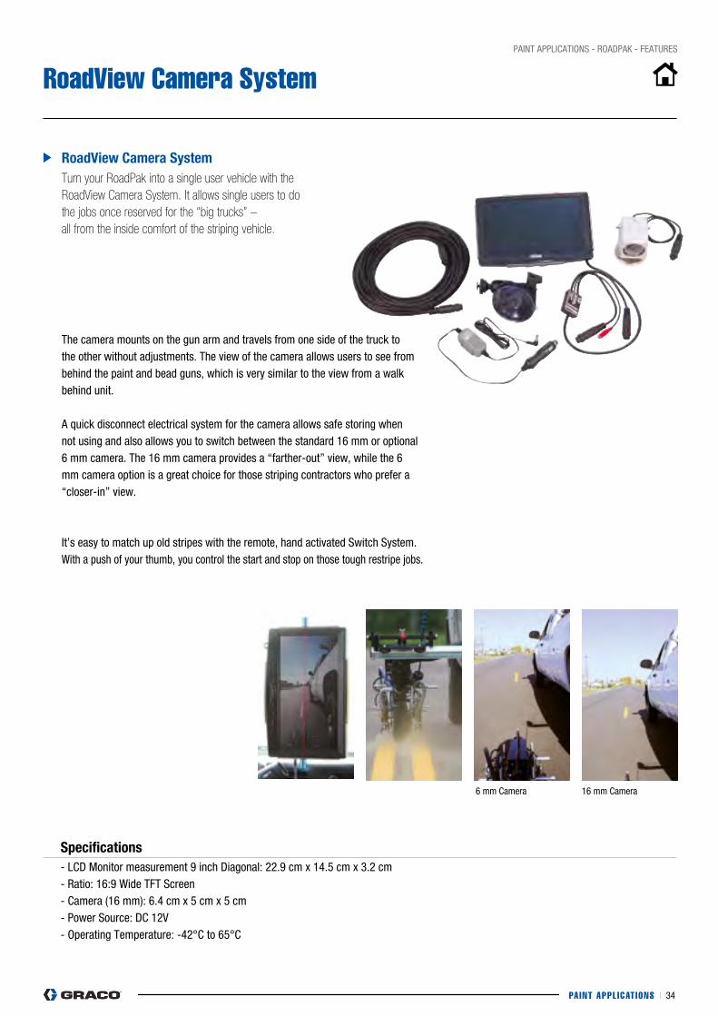
PAINT APPL ICAT IONS I 34
pAINT AppLIcATIONS - ROADpAK - FEATURES
RoadView Camera System
RoadView Camera systemTurn your RoadPak into a single user vehicle with the RoadView Camera System. It allows single users to do the jobs once reserved for the “big trucks” – all from the inside comfort of the striping vehicle.
The camera mounts on the gun arm and travels from one side of the truck to the other without adjustments. The view of the camera allows users to see from behind the paint and bead guns, which is very similar to the view from a walk behind unit.
A quick disconnect electrical system for the camera allows safe storing when not using and also allows you to switch between the standard 16 mm or optional 6 mm camera. The 16 mm camera provides a “farther-out” view, while the 6 mm camera option is a great choice for those striping contractors who prefer a “closer-in” view.
It’s easy to match up old stripes with the remote, hand activated Switch System. With a push of your thumb, you control the start and stop on those tough restripe jobs.
specifications- LcD Monitor measurement 9 inch Diagonal: 22.9 cm x 14.5 cm x 3.2 cm- Ratio: 16:9 Wide TFT Screen- camera (16 mm): 6.4 cm x 5 cm x 5 cm- power Source: Dc 12V- Operating Temperature: -42°c to 65°c
6 mm camera 16 mm camera
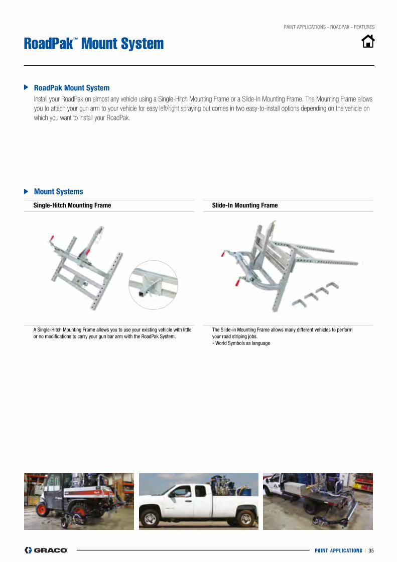
PAINT APPL ICAT IONS I 35
pAINT AppLIcATIONS - ROADpAK - FEATURES
RoadPak™ Mount System
RoadPak Mount systemInstall your RoadPak on almost any vehicle using a Single-Hitch Mounting Frame or a Slide-In Mounting Frame. The Mounting Frame allows you to attach your gun arm to your vehicle for easy left/right spraying but comes in two easy-to-install options depending on the vehicle on which you want to install your RoadPak.
single-hitch Mounting frame
A Single-Hitch Mounting Frame allows you to use your existing vehicle with little or no modifications to carry your gun bar arm with the Roadpak System.
slide-in Mounting frame
The Slide-in Mounting Frame allows many different vehicles to perform your road striping jobs. - World Symbols as language
Mount systems
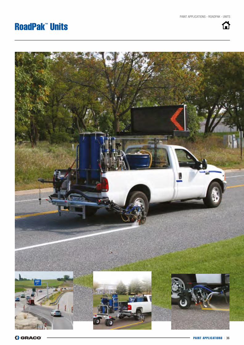
PAINT APPL ICAT IONS I 36
pAINT AppLIcATIONS - ROADpAK - UNITS
RoadPak™ Units
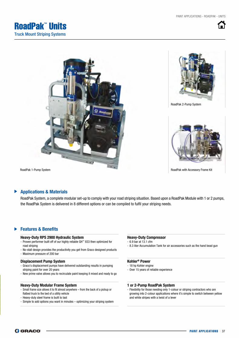
PAINT APPL ICAT IONS I 37
pAINT AppLIcATIONS - ROADpAK - UNITS
RoadPak™ UnitsTruck Mount Striping Systems
heavy-Duty RPs 2900 hydraulic system- proven performer built off of our highly reliable GH™ 833 then optimized for road striping- No-stall design provides the productivity you get from Graco designed products- Maximum pressure of 200 bar
heavy-Duty Compressor- 6.9 bar at 13.1 cfm- 8.3 liter Accumulation Tank for air accessories such as the hand bead gun
Displacement Pump system- Graco’s displacement pumps have delivered outstanding results in pumping striping paint for over 20 years- New prime valve allows you to recirculate paint keeping it mixed and ready to go
kohler® Power- 18 hp Kohler engine- Over 15 years of reliable experience
heavy-Duty Modular frame system- Small frame size allows it to fit almost anywhere – from the back of a pickup or flatbed truck to the bed of a utility vehicle- Heavy-duty steel frame is built to last - Simple to add options you want in minutes – optimizing your striping system
1 or 2-Pump RoadPak system- Flexibility for those needing only 1-colour or striping contractors who are growing into 2-colour applications where it’s simple to switch between yellow and white stripes with a twist of a lever
features & Benefits
Applications & Materials
Roadpak 1-pump System Roadpak with Accessory Frame Kit
Roadpak 2-pump System
Roadpak System, a complete modular set-up to comply with your road striping situation. Based upon a Roadpak Module with 1 or 2 pumps, the Roadpak System is delivered in 8 different options or can be compiled to fulfil your striping needs.
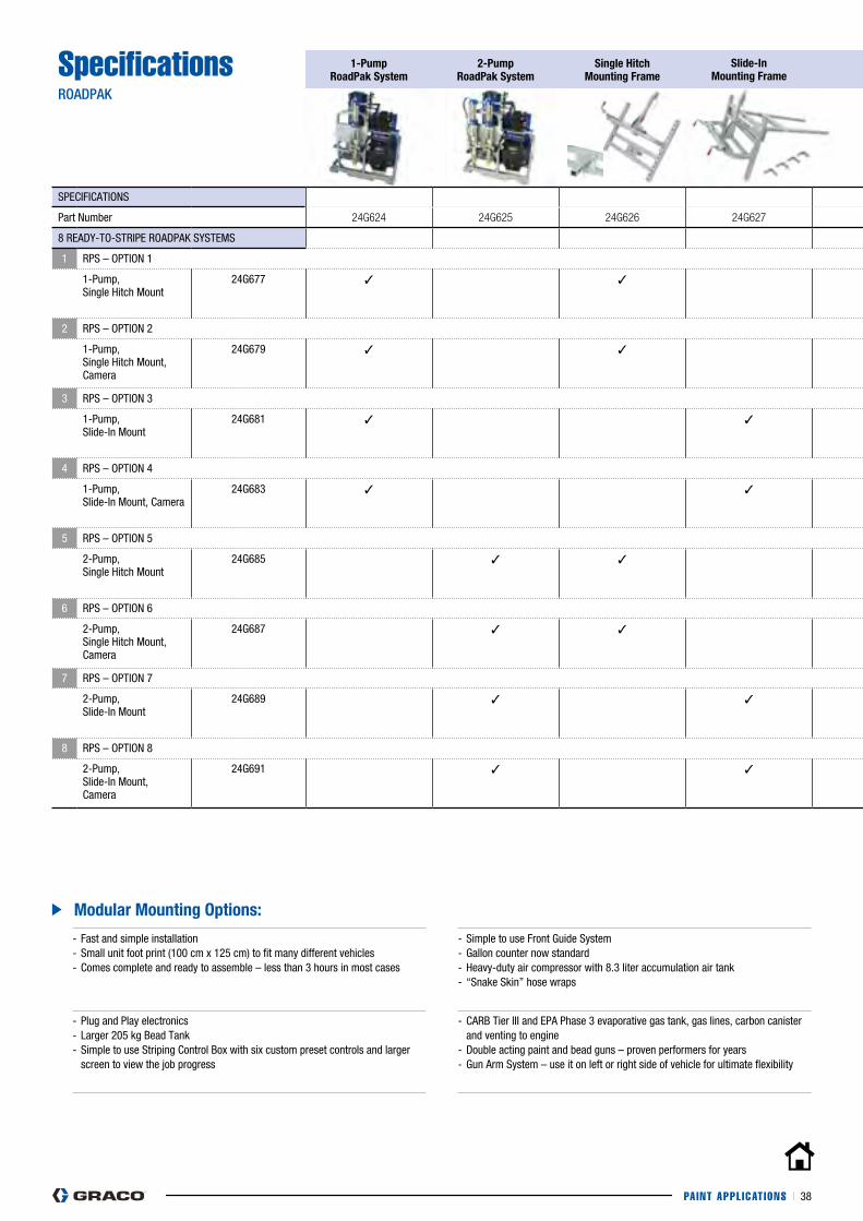
PAINT APPL ICAT IONS I 38
- Fast and simple installation- Small unit foot print (100 cm x 125 cm) to fit many different vehicles- comes complete and ready to assemble – less than 3 hours in most cases
- Simple to use Front Guide System- Gallon counter now standard- Heavy-duty air compressor with 8.3 liter accumulation air tank- “Snake Skin” hose wraps
- plug and play electronics- Larger 205 kg Bead Tank- Simple to use Striping control Box with six custom preset controls and larger screen to view the job progress
- cARB Tier III and EpA phase 3 evaporative gas tank, gas lines, carbon canister and venting to engine- Double acting paint and bead guns – proven performers for years- Gun Arm System – use it on left or right side of vehicle for ultimate flexibility
Modular Mounting Options:
SpecificationsROADPAK
1-Pump RoadPak system
2-Pump RoadPak system
single hitch Mounting frame
slide-in Mounting frame
1-Pump RoadPak Arm
2-Pump RoadPak Arm
Adjustable Gun Arm Beam
Roadlazer/RoadPak Control
RoadView-Camera system
simple Guide system
SpEcIFIcATIONS
part Number 24G624 24G625 24G626 24G627 24G628 24G629 24G630 24G632 24G633 24G634
8 READy-TO-STRIpE ROADpAK SySTEMS
1 RpS – OpTION 1
1-pump, Single Hitch Mount
24G677 ✓ ✓ ✓ ✓ ✓ ✓
2 RpS – OpTION 2
1-pump,Single Hitch Mount, camera
24G679 ✓ ✓ ✓ ✓ ✓ ✓ ✓
3 RpS – OpTION 3
1-pump,Slide-In Mount
24G681 ✓ ✓ ✓ ✓ ✓ ✓
4 RpS – OpTION 4
1-pump,Slide-In Mount, camera
24G683 ✓ ✓ ✓ ✓ ✓ ✓ ✓
5 RpS – OpTION 5
2-pump,Single Hitch Mount
24G685 ✓ ✓ ✓ ✓ ✓ ✓
6 RpS – OpTION 6
2-pump,Single Hitch Mount, camera
24G687 ✓ ✓ ✓ ✓ ✓ ✓ ✓
7 RpS – OpTION 7
2-pump,Slide-In Mount
24G689 ✓ ✓ ✓ ✓ ✓ ✓
8 RpS – OpTION 8
2-pump,Slide-In Mount, camera
24G691 ✓ ✓ ✓ ✓ ✓ ✓ ✓
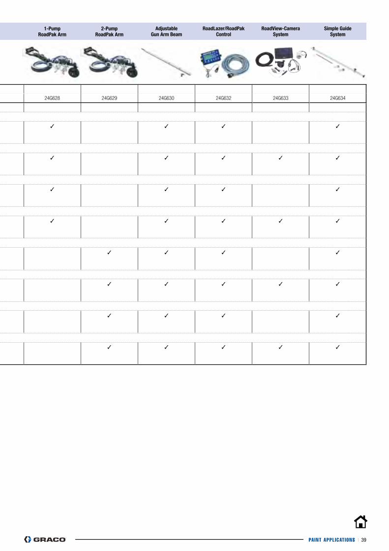
PAINT APPL ICAT IONS I 39
SpecificationsROADPAK
1-Pump RoadPak system
2-Pump RoadPak system
single hitch Mounting frame
slide-in Mounting frame
1-Pump RoadPak Arm
2-Pump RoadPak Arm
Adjustable Gun Arm Beam
Roadlazer/RoadPak Control
RoadView-Camera system
simple Guide system
SpEcIFIcATIONS
part Number 24G624 24G625 24G626 24G627 24G628 24G629 24G630 24G632 24G633 24G634
8 READy-TO-STRIpE ROADpAK SySTEMS
1 RpS – OpTION 1
1-pump, Single Hitch Mount
24G677 ✓ ✓ ✓ ✓ ✓ ✓
2 RpS – OpTION 2
1-pump,Single Hitch Mount, camera
24G679 ✓ ✓ ✓ ✓ ✓ ✓ ✓
3 RpS – OpTION 3
1-pump,Slide-In Mount
24G681 ✓ ✓ ✓ ✓ ✓ ✓
4 RpS – OpTION 4
1-pump,Slide-In Mount, camera
24G683 ✓ ✓ ✓ ✓ ✓ ✓ ✓
5 RpS – OpTION 5
2-pump,Single Hitch Mount
24G685 ✓ ✓ ✓ ✓ ✓ ✓
6 RpS – OpTION 6
2-pump,Single Hitch Mount, camera
24G687 ✓ ✓ ✓ ✓ ✓ ✓ ✓
7 RpS – OpTION 7
2-pump,Slide-In Mount
24G689 ✓ ✓ ✓ ✓ ✓ ✓
8 RpS – OpTION 8
2-pump,Slide-In Mount, camera
24G691 ✓ ✓ ✓ ✓ ✓ ✓ ✓
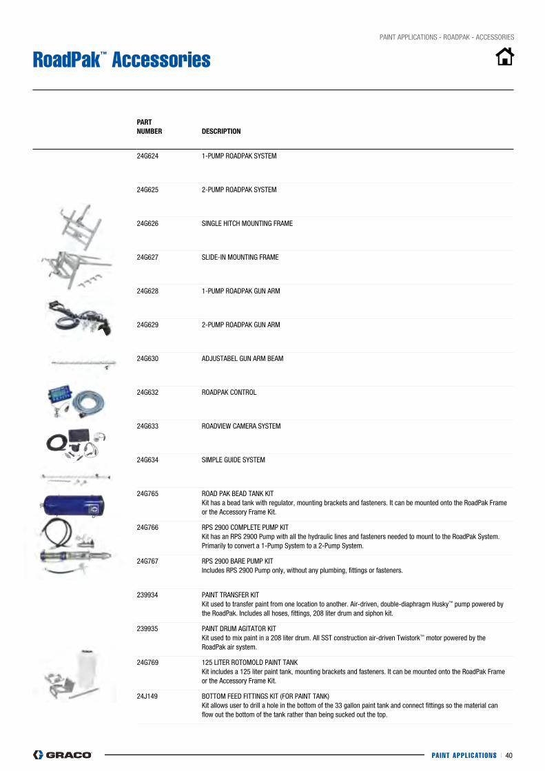
PAINT APPL ICAT IONS I 40
pAINT AppLIcATIONS - ROADpAK - AccESSORIES
RoadPak™ Accessories
PART nUMBeR
DesCRiPTiOn
24G624 1-pUMp ROADpAK SySTEM
24G625 2-pUMp ROADpAK SySTEM
24G626 SINGLE HITcH MOUNTING FRAME
24G627 SLIDE-IN MOUNTING FRAME
24G628 1-pUMp ROADpAK GUN ARM
24G629 2-pUMp ROADpAK GUN ARM
24G630 ADjUSTABEL GUN ARM BEAM
24G632 ROADpAK cONTROL
24G633 ROADVIEW cAMERA SySTEM
24G634 SIMpLE GUIDE SySTEM
24G765 ROAD pAK BEAD TANK KITKit has a bead tank with regulator, mounting brackets and fasteners. It can be mounted onto the Roadpak Frame or the Accessory Frame Kit.
24G766 RpS 2900 cOMpLETE pUMp KIT Kit has an RpS 2900 pump with all the hydraulic lines and fasteners needed to mount to the Roadpak System. primarily to convert a 1-pump System to a 2-pump System.
24G767 RpS 2900 BARE pUMp KIT Includes RpS 2900 pump only, without any plumbing, fittings or fasteners.
239934 pAINT TRANSFER KIT Kit used to transfer paint from one location to another. Air-driven, double-diaphragm Husky™ pump powered by the Roadpak. Includes all hoses, fittings, 208 liter drum and siphon kit.
239935 pAINT DRUM AGITATOR KIT Kit used to mix paint in a 208 liter drum. All SST construction air-driven Twistork™ motor powered by the Roadpak air system.
24G769 125 LITER ROTOMOLD pAINT TANK Kit includes a 125 liter paint tank, mounting brackets and fasteners. It can be mounted onto the Roadpak Frame or the Accessory Frame Kit.
24j149 BOTTOM FEED FITTINGS KIT (FOR pAINT TANK) Kit allows user to drill a hole in the bottom of the 33 gallon paint tank and connect fittings so the material can flow out the bottom of the tank rather than being sucked out the top.
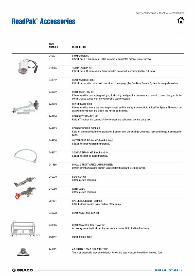
PAINT APPL ICAT IONS I 41
pAINT AppLIcATIONS - ROADpAK - AccESSORIES
RoadPak™ Accessories
PART nUMBeR
DesCRiPTiOn
24G771 6 MM cAMERA KIT Kit includes a 6 mm camera. cable included to connect to monitor (closer in view)
24H555 16 MM cAMERA KIT Kit includes a 16 mm camera. cable included to connect to monitor (farther out view).
24H612 ROADpAK MONITOR KIT Kit includes monitor, windshield mount and power plug. (See RoadView camera System for complete system).
24G772 ROADpAK 3RD GUN KIT Kit comes with a dual acting paint gun, dual acting bead gun, the hardware and hoses to connect the guns to the system. It also comes with three adjustable bead deflectors.
24G773 GUN LIFT/WINcH KIT Kit comes with a winch, the mounting brackets, and the wiring to connect it to a Roadpak System. The winch can easily be moved from one side of the vehicle to the other.
24G774 ROADpAK y-STRAINER KIT Kit is a y-strainer that connects inline between the paint drum and the pump inlet.
24G775 ROADpAK DOUBLE DROp KIT Kit is for element double drop application. It comes with one bead gun, one bead hose and fittings to connect the parts.
24G776 WATERBORNE SIpHON KIT (Roadpak Only) Suction hose for waterborne materials.
24G777 SOLVENT SIpHON KIT (Roadpak Only) Suction hose for oil-based materials.
241880 DyNAMIc FRONT ARTIcULATING pOINTER Dynamic front articulating pointer. Excellent for those hard-to-stripe curves.
24G979 BEAD GUN KIT Kit for a single bead gun.
24G980 pAINT GUN KIT Kit for a single paint gun.
287834 RpS DISpLAcEMENT pUMp KIT Kit is the lower section (paint portion) of the pump.
24G778 ROADpAK STENcIL GUN KIT
24H585 ROADpAK AccESSORy FRAME KIT Accessory frame that includes the hardware to connect it to the Roadpak frame.
238957 HAND BEAD GUN KIT
24j173 ADjUSTABLE BEAD GUN DEFLEcTOR This is an adjustable bead gun deflector. Allows the user to adjust the width of the bead flow.

THERMOPLAST IC APPL ICAT IONS I 42
THERMOPLASTIC APPLICATIONS
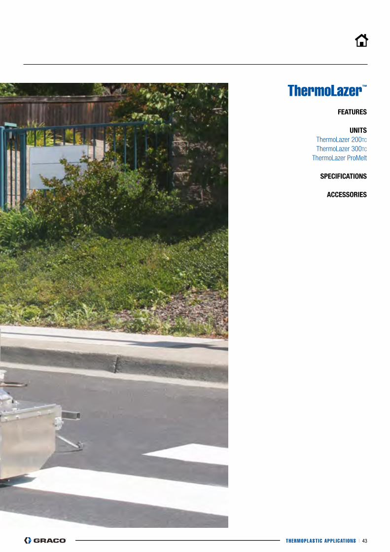
THERMOPLAST IC APPL ICAT IONS I 43
ThermoLazer™ feATURes
UniTs ThermoLazer 200TC
ThermoLazer 300TC
ThermoLazer ProMelt
sPeCifiCATiOns
ACCessORies
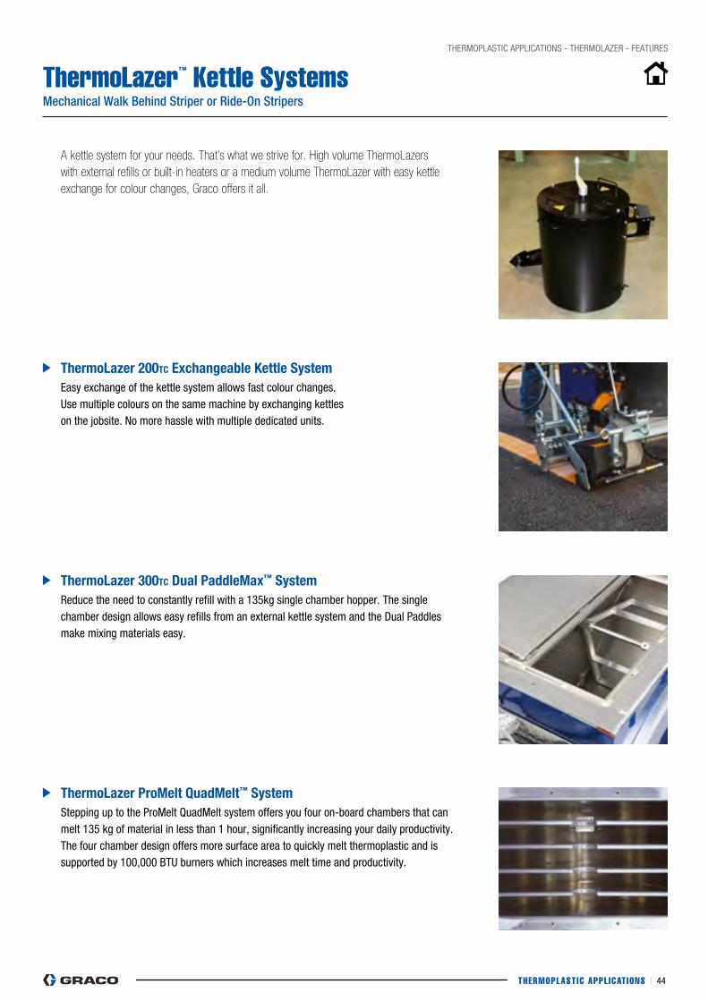
THERMOPLAST IC APPL ICAT IONS I 44
THERMOpLASTIc AppLIcATIONS - THERMOLAZER - FEATURES
ThermoLazer™ Kettle Systems Mechanical Walk Behind Striper or Ride-On Stripers
Thermolazer 200TC exchangeable kettle system
Thermolazer 300TC Dual PaddleMax™ system
Thermolazer ProMelt QuadMelt™ system
Easy exchange of the kettle system allows fast colour changes. Use multiple colours on the same machine by exchanging kettles on the jobsite. No more hassle with multiple dedicated units.
Reduce the need to constantly refill with a 135kg single chamber hopper. The single chamber design allows easy refills from an external kettle system and the Dual paddles make mixing materials easy.
Stepping up to the proMelt QuadMelt system offers you four on-board chambers that can melt 135 kg of material in less than 1 hour, significantly increasing your daily productivity. The four chamber design offers more surface area to quickly melt thermoplastic and is supported by 100,000 BTU burners which increases melt time and productivity.
A kettle system for your needs. That’s what we strive for. High volume ThermoLazers with external refills or built-in heaters or a medium volume ThermoLazer with easy kettle exchange for colour changes, Graco offers it all.
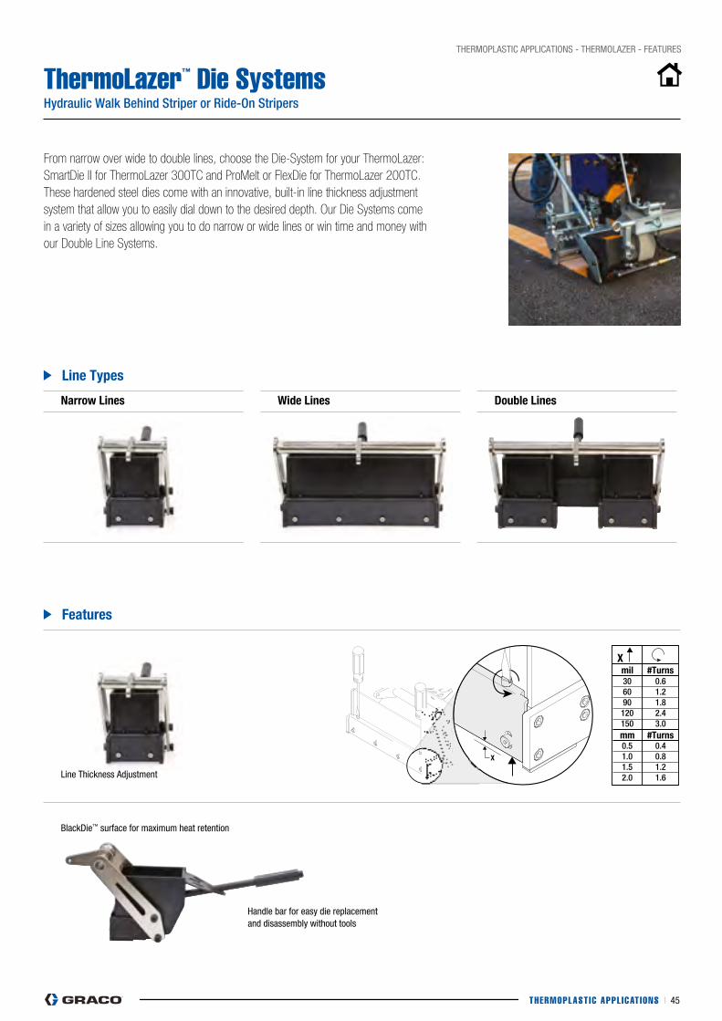
28 3A1319E
X
X mil # Turns 30 0.6 60 1.2 90 1.8 120 2.4 150 3.0 mm # Turns 0.5 0.4 1.0 0.8 1.5 1.2 2.0 1.6
ti17046a
THERMOPLAST IC APPL ICAT IONS I 45
THERMOpLASTIc AppLIcATIONS - THERMOLAZER - FEATURES
ThermoLazer™ Die SystemsHydraulic Walk Behind Striper or Ride-On Stripers
From narrow over wide to double lines, choose the Die-System for your ThermoLazer: SmartDie II for ThermoLazer 300TC and ProMelt or FlexDie for ThermoLazer 200TC. These hardened steel dies come with an innovative, built-in line thickness adjustment system that allow you to easily dial down to the desired depth. Our Die Systems come in a variety of sizes allowing you to do narrow or wide lines or win time and money with our Double Line Systems.
narrow lines wide lines Double lines
line Types
features
Line Thickness Adjustment
BlackDie™ surface for maximum heat retention
Handle bar for easy die replacement and disassembly without tools
mil #Turns
mm #Turns

THERMOPLAST IC APPL ICAT IONS I 46
THERMOpLASTIc AppLIcATIONS - THERMOLAZER - UNITS
ThermoLazer™ Units
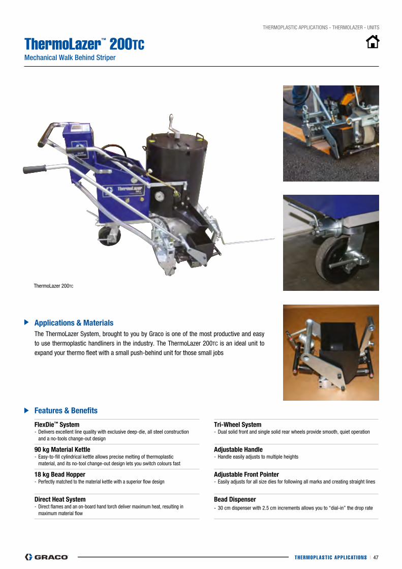
THERMOPLAST IC APPL ICAT IONS I 47
THERMOpLASTIc AppLIcATIONS - THERMOLAZER - UNITS
ThermoLazer™ 200TCMechanical Walk Behind Striper
flexDie™ system- Delivers excellent line quality with exclusive deep-die, all steel construction and a no-tools change-out design
Tri-wheel system- Dual solid front and single solid rear wheels provide smooth, quiet operation
90 kg Material kettle- Easy-to-fill cylindrical kettle allows precise melting of thermoplastic material, and its no-tool change-out design lets you switch colours fast
Adjustable handle- Handle easily adjusts to multiple heights
18 kg Bead hopper- perfectly matched to the material kettle with a superior flow design
Adjustable front Pointer- Easily adjusts for all size dies for following all marks and creating straight lines
Direct heat system- Direct flames and an on-board hand torch deliver maximum heat, resulting in maximum material flow
Bead Dispenser- 30 cm dispenser with 2.5 cm increments allows you to “dial-in” the drop rate
features & Benefits
Applications & Materials
ThermoLazer 200Tc
The ThermoLazer System, brought to you by Graco is one of the most productive and easy to use thermoplastic handliners in the industry. The ThermoLazer 200Tc is an ideal unit to expand your thermo fleet with a small push-behind unit for those small jobs
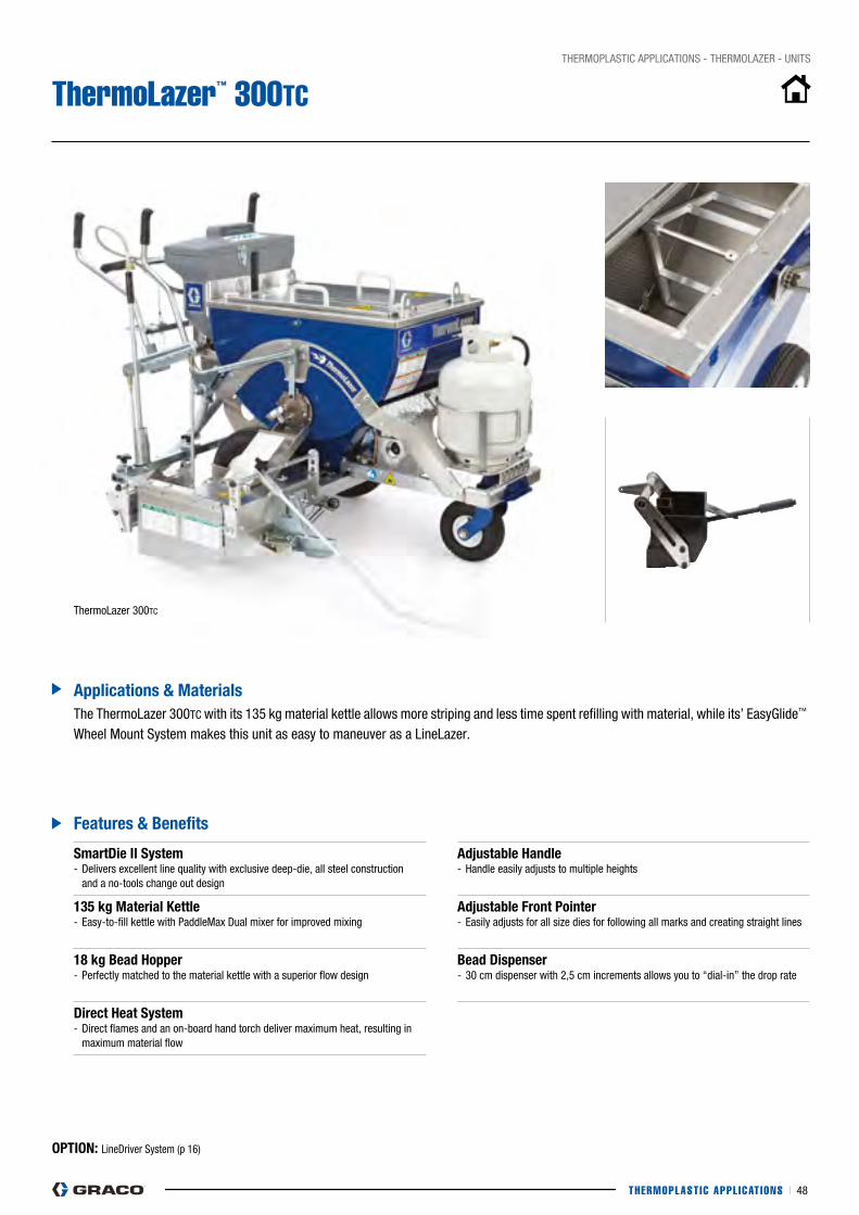
THERMOPLAST IC APPL ICAT IONS I 48
THERMOpLASTIc AppLIcATIONS - THERMOLAZER - UNITS
ThermoLazer™ 300TC
features & Benefits
Applications & Materials
ThermoLazer 300Tc
The ThermoLazer 300Tc with its 135 kg material kettle allows more striping and less time spent refilling with material, while its’ EasyGlide™ Wheel Mount System makes this unit as easy to maneuver as a LineLazer.
smartDie ii system - Delivers excellent line quality with exclusive deep-die, all steel construction and a no-tools change out design
Adjustable handle - Handle easily adjusts to multiple heights
135 kg Material kettle- Easy-to-fill kettle with paddleMax Dual mixer for improved mixing
Adjustable front Pointer- Easily adjusts for all size dies for following all marks and creating straight lines
18 kg Bead hopper- perfectly matched to the material kettle with a superior flow design
Bead Dispenser- 30 cm dispenser with 2,5 cm increments allows you to “dial-in” the drop rate
Direct heat system- Direct flames and an on-board hand torch deliver maximum heat, resulting in maximum material flow
OPTiOn: LineDriver System (p 16)
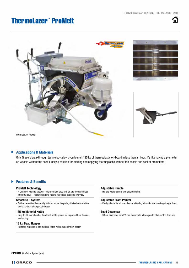
™
THERMOPLAST IC APPL ICAT IONS I 49
THERMOpLASTIc AppLIcATIONS - THERMOLAZER - UNITS
ThermoLazer™ ProMelt
features & Benefits
Applications & Materials
ThermoLazer proMelt
Only Graco’s breakthrough technology allows you to melt 135 kg of thermoplastic on-board in less than an hour. It’s like having a premelter on wheels without the cost. Finally a solution for melting and applying thermoplastic without the hassle and cost of premelters.
ProMelt Technology - 4 chamber Melting System—More surface area to melt thermoplastic fast- 100,000 BTUs—Faster melt time means more jobs get done everyday
Adjustable handle - Handle easily adjusts to multiple heights
smartDie ii system- Delivers excellent line quality with exclusive deep-die, all steel construction and a no-tools change-out design
Adjustable front Pointer- Easily adjusts for all size dies for following all marks and creating straight lines
135 kg Material kettle- Easy-to-fill four chamber Quadmelt kettle system for improved heat transfer and mixing
Bead Dispenser- 30 cm dispenser with 2,5 cm increments allows you to “dial-in” the drop rate
18 kg Bead hopper- perfectly matched to the material kettle with a superior flow design
OPTiOn: LineDriver System (p 16)

THERMOPLAST IC APPL ICAT IONS I 50
SpecificationsUNITS
Thermolazer 200TC Thermolazer 300TC Thermolazer ProMelt
SpEcIFIcATIONS
part Number - unit only 24U281 24H622 24H624
Fuel LP gas (LP tank not included)
LP gas (LP tank not included)
LP gas (LP tank not included)
Die Heater system Tri-Flame Tri-Flame
Main Burners 30.000 BTU 30.000 BTU 100.000 BTU
Material capacity – kg (lb) 90 (200) 135 (300) 135 (300)
Melt Time for full capacity Thermoplastic
4-4,5 hours without premelt system
Less than 1 hour
Melt chamber Single Single QuadMelt
Bead Hopper capacity – kg (lbs) 18 (40) 40 (90) 40 (90)
Weight – kg (lbs) 118 (260) 133 (295) 157 (345)
FEATURES
Dies available (*) FlexDie SmartDie II SmartDie II
Temperature Limit control N/A N/A 475° F Switch
Electronic Ignition No ✓ ✓
Torch ✓ ✓ ✓
LineDriver No Optional Optional
External 4-torch die heat system Burners on FlexDie Optional Standard
Internal Mixing paddles Single mixing paddle Dual PaddleMax System QuadMix System
Hopper Lid System Flat, Single Lid Flat, Dual Lid Raised, Single Lid
Bead Dispense System 30 cm with 2.5 cm doors
30 cm with 2.5 cm doors
30 cm with 2.5 cm doors
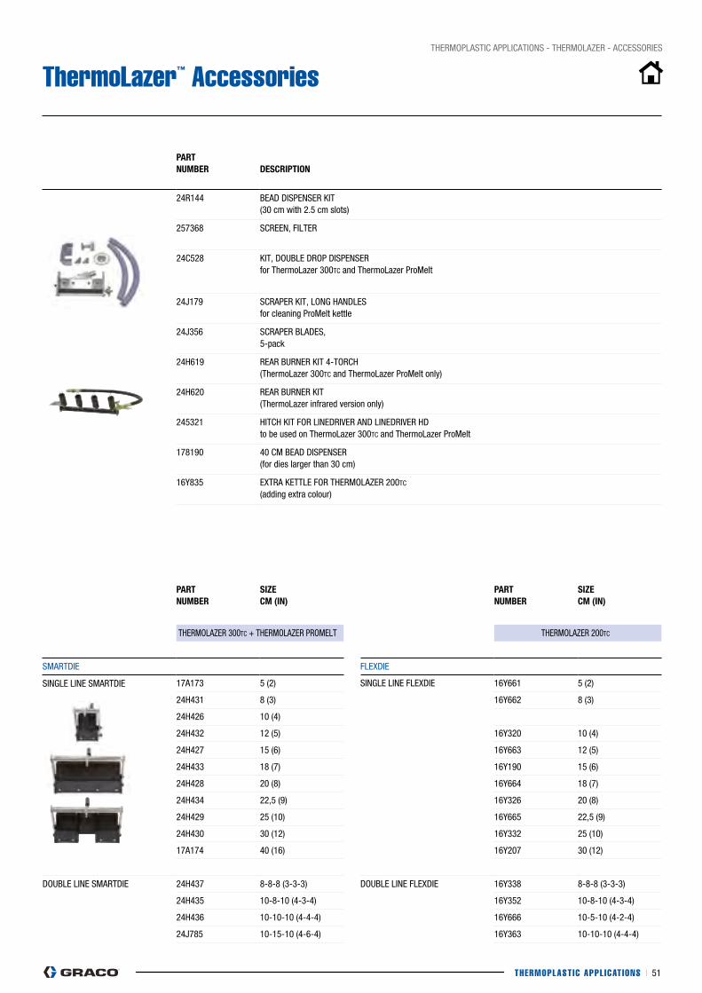
THERMOPLAST IC APPL ICAT IONS I 51
THERMOpLASTIc AppLIcATIONS - THERMOLAZER - AccESSORIES
ThermoLazer™ Accessories
PART nUMBeR
DesCRiPTiOn
24R144 BEAD DISpENSER KIT (30 cm with 2.5 cm slots)
257368 ScREEN, FILTER
24c528 KIT, DOUBLE DROp DISpENSER for ThermoLazer 300Tc and ThermoLazer proMelt
24j179 ScRApER KIT, LONG HANDLES for cleaning proMelt kettle
24j356 ScRApER BLADES, 5-pack
24H619 REAR BURNER KIT 4-TORcH (ThermoLazer 300Tc and ThermoLazer proMelt only)
24H620 REAR BURNER KIT (ThermoLazer infrared version only)
245321 HITcH KIT FOR LINEDRIVER AND LINEDRIVER HD to be used on ThermoLazer 300Tc and ThermoLazer proMelt
178190 40 cM BEAD DISpENSER (for dies larger than 30 cm)
16y835 EXTRA KETTLE FOR THERMOLAZER 200Tc (adding extra colour)
PART nUMBeR
sizeCM (in)
PART nUMBeR
sizeCM (in)
THERMOLAZER 300Tc + THERMOLAZER pROMELT THERMOLAZER 200Tc
SMARTDIE FLEXDIE
SINGLE LINE SMARTDIE 17A173 5 (2) SINGLE LINE FLEXDIE 16y661 5 (2)
24H431 8 (3) 16y662 8 (3)
24H426 10 (4)
24H432 12 (5) 16y320 10 (4)
24H427 15 (6) 16y663 12 (5)
24H433 18 (7) 16y190 15 (6)
24H428 20 (8) 16y664 18 (7)
24H434 22,5 (9) 16y326 20 (8)
24H429 25 (10) 16y665 22,5 (9)
24H430 30 (12) 16y332 25 (10)
17A174 40 (16) 16y207 30 (12)
DOUBLE LINE SMARTDIE 24H437 8-8-8 (3-3-3) DOUBLE LINE FLEXDIE 16y338 8-8-8 (3-3-3)
24H435 10-8-10 (4-3-4) 16y352 10-8-10 (4-3-4)
24H436 10-10-10 (4-4-4) 16y666 10-5-10 (4-2-4)
24j785 10-15-10 (4-6-4) 16y363 10-10-10 (4-4-4)
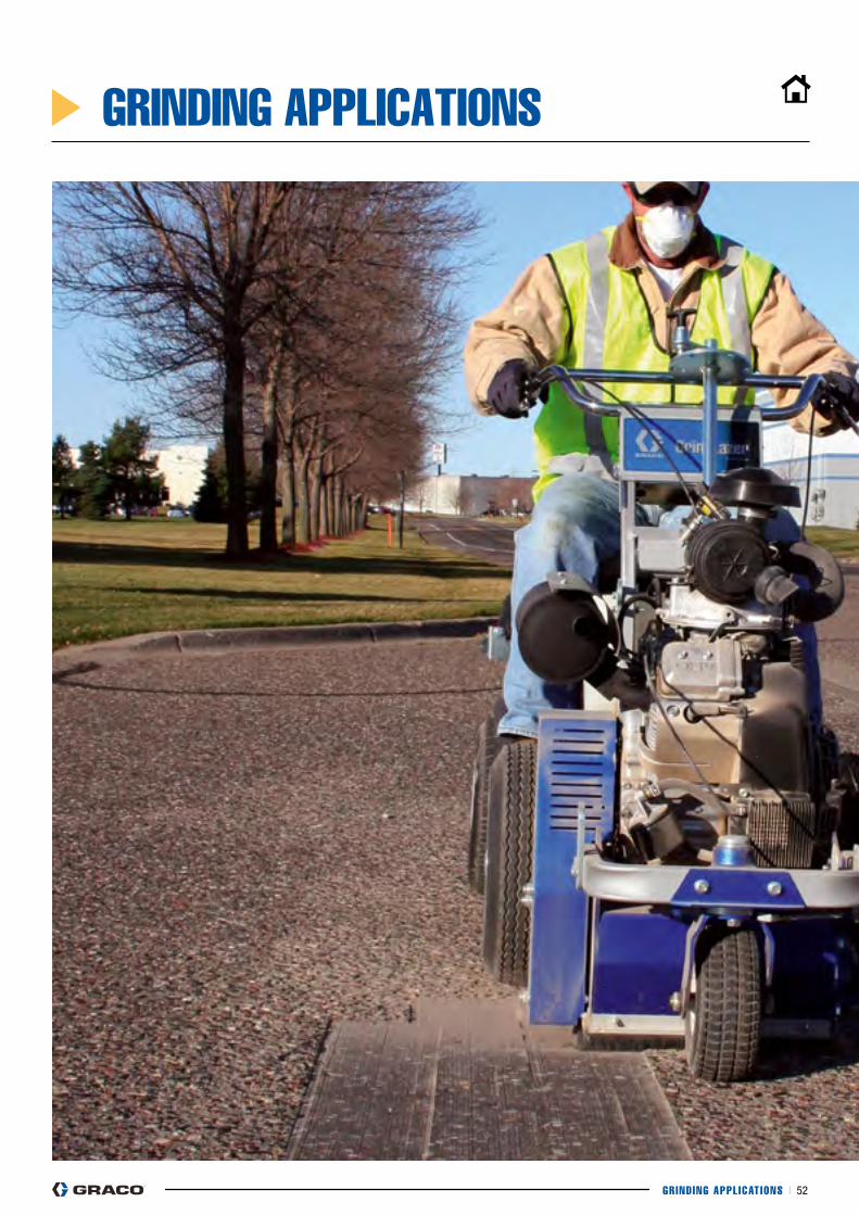
GRIND ING APPL ICAT IONS I 52
GRINDING APPLICATIONS

GRIND ING APPL ICAT IONS I 53
GrindLazer™ feATURes
UniTs GrindLazer 270GrindLazer 390 GrindLazer 630
sPeCifiCATiOns
ACCessORies
GRINDING APPLICATIONS
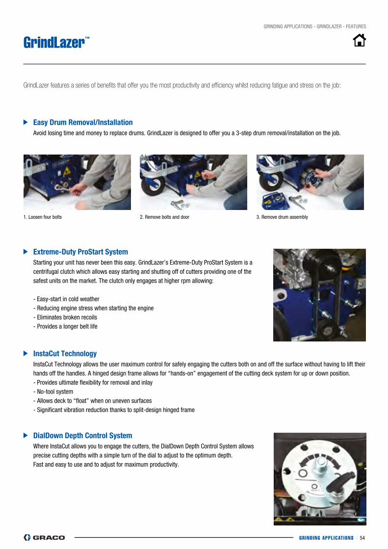
GRIND ING APPL ICAT IONS I 54
GRINDING AppLIcATIONS - GRINDLAZER - FEATURES
GrindLazer™
easy Drum Removal/installation
extreme-Duty Prostart system
instaCut Technology
DialDown Depth Control system
Avoid losing time and money to replace drums. GrindLazer is designed to offer you a 3-step drum removal/installation on the job.
Starting your unit has never been this easy. GrindLazer’s Extreme-Duty proStart System is a centrifugal clutch which allows easy starting and shutting off of cutters providing one of the safest units on the market. The clutch only engages at higher rpm allowing:
- Easy-start in cold weather- Reducing engine stress when starting the engine- Eliminates broken recoils - provides a longer belt life
Instacut Technology allows the user maximum control for safely engaging the cutters both on and off the surface without having to lift their hands off the handles. A hinged design frame allows for “hands-on” engagement of the cutting deck system for up or down position. - provides ultimate flexibility for removal and inlay- No-tool system- Allows deck to “float” when on uneven surfaces- Significant vibration reduction thanks to split-design hinged frame
Where Instacut allows you to engage the cutters, the DialDown Depth control System allows precise cutting depths with a simple turn of the dial to adjust to the optimum depth. Fast and easy to use and to adjust for maximum productivity.
GrindLazer features a series of benefits that offer you the most productivity and efficiency whilst reducing fatigue and stress on the job:
1. Loosen four bolts 2. Remove bolts and door 3. Remove drum assembly
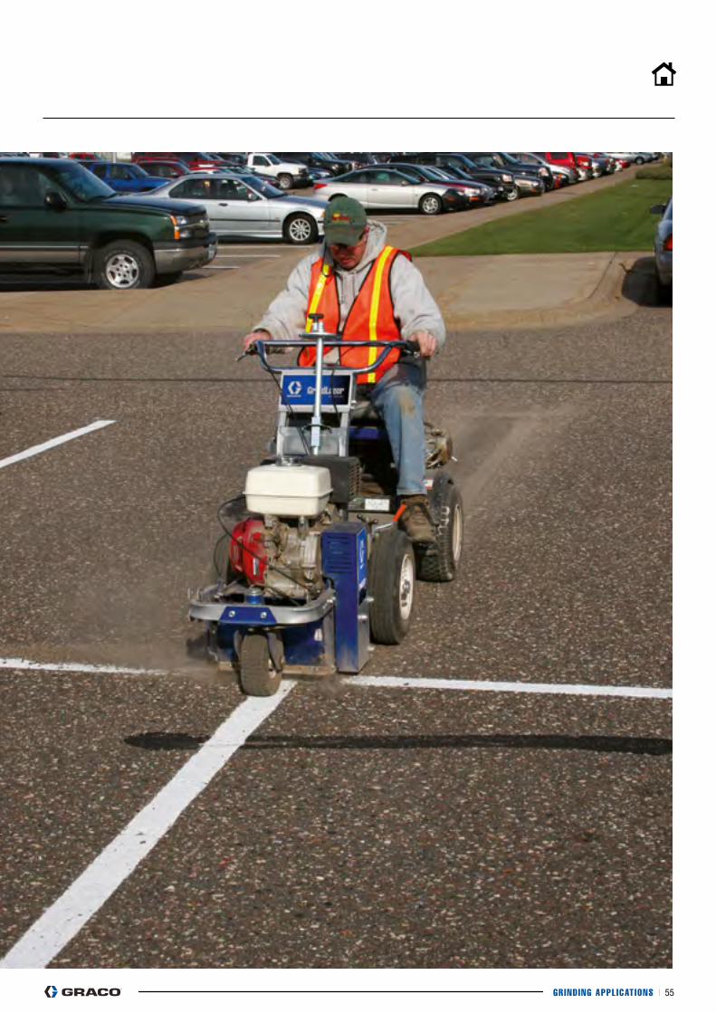
GRIND ING APPL ICAT IONS I 55
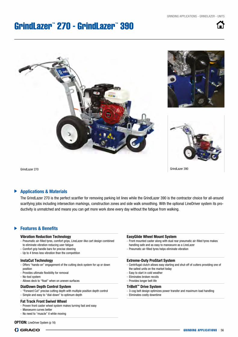
GRIND ING APPL ICAT IONS I 56
GRINDING AppLIcATIONS - GRINDLAZER - UNITS
GrindLazer™ 270 - GrindLazer™ 390
features & Benefits
Applications & Materials
GrindLazer 270
The GrindLazer 270 is the perfect scarifier for removing parking lot lines while the GrindLazer 390 is the contractor choice for all-around scarifying jobs including intersection markings, construction zones and side walk smoothing. With the optional LineDriver system its pro- ductivity is unmatched and means you can get more work done every day without the fatigue from walking.
GrindLazer 390
Vibration Reduction Technology - pneumatic air-filled tyres, comfort grips, LineLazer-like cart design combined to eliminate vibration reducing user fatigue- comfort grip handle bars for precise steering- Up to 4 times less vibration than the competition
easyGlide wheel Mount system - Front mounted caster along with dual rear pneumatic air-filled tyres makes handling safe and as easy to manoeuvre as a LineLazer- pneumatic air-filled tyres helps eliminate vibration
instaCut Technology- Offers “hands-on” engagement of the cutting deck system for up or down position- provides ultimate flexibility for removal - No-tool system- Allows deck to “float” when on uneven surfaces
extreme-Duty Prostart system- centrifugal clutch allows easy starting and shut-off of cutters providing one of the safest units on the market today- Easy to start in cold weather- Eliminates broken recoils- provides longer belt life
DialDown Depth Control system- “Forward cut” precise cutting depth with multiple position depth control - Simple and easy to “dial-down” to optimum depth
TriBelt™ Drive system- 3-cog belt design optimizes power transfer and maximum load handling- Eliminates costly downtime
fat Track front swivel wheel- proven front caster wheel system makes turning fast and easy - Manoeuvre curves better - No need to “muscle” it while moving
OPTiOn: LineDriver System (p 16)

GRIND ING APPL ICAT IONS I 57
GRINDING AppLIcATIONS - GRINDLAZER - UNITS
GrindLazer™ 630
Vibration Reduction Technology- pneumatic air-filled tyres, comfort grips, LineLazer-like cart design combined to eliminate vibration reducing user fatigue- comfort grip handle bars for precise steering- Up to 4 times less vibration than the competition
lineDriver RequiredGrindLazer 630 with Reverse/“Up-cut” cutting direction requires the use of a LineDriver propel System.The GrindLazer 630 unit cannot operate without a LineDriver due to the proStart safety switch interlock system.
extreme-Duty Prostart system- centrifugal clutch allows easy starting and shut-off of cutters providing one of the safest units on the market today- Easy to start in cold weather- Eliminates broken recoils- provides longer belt life
instaCut Technology- Offers “hands-on” engagement of the cutting deck system for up or down position- provides ultimate flexibility for removal and inlay- No-tool system- Allows deck to “float” when on uneven surfaces
features & Benefits
Applications & Materials
GrindLazer 630
The GrindLazer 630 is the high production choice when it comes to the most demanding scarifier jobs. With its “Up-cut” cutting direction, not only you are able to remove all types of lines found on parking lots or road, but now have the power to do inlay/grooving jobs. combined with the LineDriver, you’ll finish jobs faster and more accurately than ever before!
OPTiOn: LineDriver System (p 16)
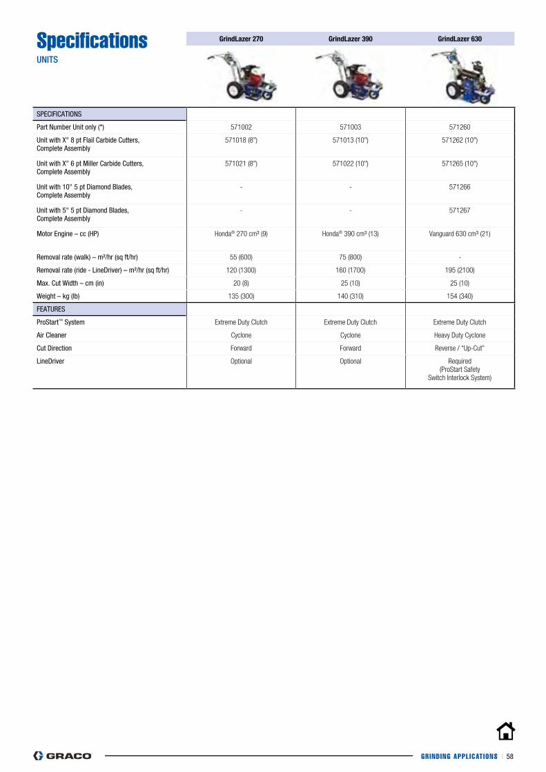
GRIND ING APPL ICAT IONS I 58
SpecificationsUNITS
Grindlazer 270 Grindlazer 390 Grindlazer 630
SpEcIFIcATIONS
part Number Unit only (*) 571002 571003 571260
Unit with X" 8 pt Flail carbide cutters, complete Assembly
571018 (8") 571013 (10") 571262 (10")
Unit with X" 6 pt Miller carbide cutters, complete Assembly
571021 (8") 571022 (10") 571265 (10")
Unit with 10" 5 pt Diamond Blades, complete Assembly
- - 571266
Unit with 5" 5 pt Diamond Blades, complete Assembly
- - 571267
Motor Engine – cc (Hp) Honda® 270 cm³ (9) Honda® 390 cm³ (13) Vanguard 630 cm³ (21)
Removal rate (walk) – m²/hr (sq ft/hr) 55 (600) 75 (800) -
Removal rate (ride - LineDriver) – m²/hr (sq ft/hr) 120 (1300) 160 (1700) 195 (2100)
Max. cut Width – cm (in) 20 (8) 25 (10) 25 (10)
Weight – kg (lb) 135 (300) 140 (310) 154 (340)
FEATURES
proStart™ System Extreme Duty Clutch Extreme Duty Clutch Extreme Duty Clutch
Air cleaner Cyclone Cyclone Heavy Duty Cyclone
cut Direction Forward Forward Reverse / “Up-Cut”
LineDriver Optional Optional Required (ProStart Safety
Switch Interlock System)
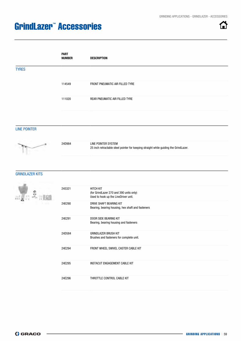
GRIND ING APPL ICAT IONS I 59
PART nUMBeR
DesCRiPTiOn
TyRES
114549 FRONT pNEUMATIc AIR FILLED TyRE
111020 REAR pNEUMATIc AIR FILLED TyRE
LINE pOINTER
24D984 LINE pOINTER SySTEM25 inch retractable steel pointer for keeping straight while guiding the GrindLazer.
GRINDLAZER KITS
245321 HITcH KIT (for GrindLazer 270 and 390 units only)Used to hook up the LineDriver unit.
24E290 DRIVE SHAFT BEARING KITBearing, bearing housing, hex shaft and fasteners
24E291 DOOR SIDE BEARING KITBearing, bearing housing and fasteners
24D584 GRINDLAZER BRUSH KITBrushes and fasteners for complete unit.
24E294 FRONT WHEEL SWIVEL cASTER cABLE KIT
24E295 INSTAcUT ENGAGEMENT cABLE KIT
24E296 THROTTLE cONTROL cABLE KIT
GRINDING AppLIcATIONS - GRINDLAZER - AccESSORIES
GrindLazer™ Accessories
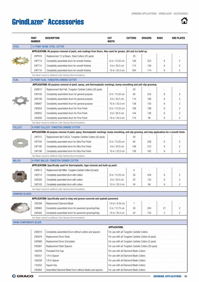
GRIND ING APPL ICAT IONS I 60
GRINDING AppLIcATIONS - GRINDLAZER - AccESSORIES
GrindLazer™ Accessories
PART nUMBeR
DesCRiPTiOn CUTwiDTh
CUTTeRs sPACeRs RODs enD PlATes
STEEL 12-pOINT BEAM: STEEL cUTTER
APPliCATiOn: All purpose removal of paint, and coatings from floors. Also used for grease, dirt and ice build up.
24P818 Replacement 12 pt Beam, Steel Cutters (25 pack) 25 - - -
24P714 Completely assembled drum for smooth finishes 6 in / 15.25 cm 126 222 6 2
24P715 Completely assembled drum for smooth finishes 8 in / 20.5 cm 174 156 6 2
24P716 Completely assembled drum for smooth finishes 10 in / 25.5 cm 204 114 6 2
See Repair manual for additional Cutter Stacking Recommendations.
FLAIL 8-pOINT FLAIL: TUNGSTEN cARBIDE cUTTER
APPliCATiOn: All purpose removal of paint, epoxy, and thermoplastic markings, bump-smoothing and anti-slip grooving.
24D612 Replacement 8pt Flail, Tungsten Carbide Cutters (20 pack) - 20 - - -
24D182 Completely assembled drum for general purpose 6 in / 15.25 cm 84 234 6 2
24D180 Completely assembled drum for general purpose 8 in / 20.5 cm 114 186 6 2
24B957 Completely assembled drum for general purpose 10 in / 25.5 cm 138 150 6 2
24E854 Completely assembled drum for Fine Finish 6 in / 15.25 cm 108 198 6 2
24E855 Completely assembled drum for Fine Finish 8 in / 20.5 cm 144 138 6 2
24E856 Completely assembled drum for Fine Finish 10 in / 25.5 cm 174 90 6 2
See Repair manual for additional Cutter Stacking Recommendations.
FULLcUT 8-pOINT FULLcUT: TUNGSTEN cARBIDE cUTTER
APPliCATiOn: All purpose removal of paint, epoxy, thermoplastic markings, bump-smoothing, anti-slip grooving, and inlay applications for a smooth finish.
24F213 Replacement 8pt FullCut, Tungsten Carbide Cutters (20 pack) - 20 - - -
24F184 Completely assembled drum for Ultra Fine Finish 6 in / 15.25 cm 84 258 6 2
24F185 Completely assembled drum for Ultra Fine Finish 8 in / 20.5 cm 108 210 6 2
24F186 Completely assembled drum for Ultra Fine Finish 10 in / 25.5 cm 138 162 6 2
See Repair manual for additional Cutter Stacking Recommendations.
MILLER 6-pOINT MILLER: TUNGSTEN cARBIDE cUTTER
APPliCATiOn: Specifically used for thermoplastic, tape removal and built-up paint.
24D613 Replacement 6pt Miller, Tungsten Carbide Cutters (6 pack) - 6 - - -
24E214 Completely assembled drum with cutters 6 in / 15.25 cm 30 204 6 2
24D585 Completely assembled drum with cutters 8 in / 20.5 cm 42 132 6 2
24D183 Completely assembled drum with cutters 10 in / 25.5 cm 54 66 6 2
See Repair manual for additional Cutter Stacking Recommendations.
DIAMOND BLADES
APPliCATiOn: Specifically used to inlay and groove concrete and asphalt pavement.
24E289 Replacement Diamond Blade 1/4 in / 6.35 cm 1 - - -
24B965 Completely assembled drum for pavement grooving/inlay 5 in / 12.75 cm 30 204 21 2
24D583 Completely assembled drum for pavement grooving/inlay 10 in / 25.5 cm 42 132 2 2
See Repair manual for additional Cutter Stacking Recommendations.
DRUM cOMpONENTS BLADE
APPliCATiOn:
24D610 Completely assembled Drum without cutters and spacers For use with all Tungsten Carbide Cutters
24D979 Replacement Drum Rods For use with all Tungsten Carbide Cutters (6 pack)
24D980 Replacement Drum End plates For use with all Tungsten Carbide Cutters (2 pack)
24D981 Replacement Steel Spacers For use with all Tungsten Carbide Cutters (20 pack)
16A259 Threaded End Cap For use with all Diamond Blade Cutters
16A257 1/4 in Spacer For use with all Diamond Blade Cutters
16A258 1/8 in Spacer For use with all Diamond Blade Cutters
123252 Square Key For use with all Diamond Blade Cutters
24D982 Assembled Diamond Blade Drum without blades and spacers For use with all Diamond Blade Cutters
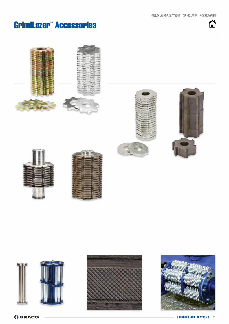
GRIND ING APPL ICAT IONS I 61
GRINDING AppLIcATIONS - GRINDLAZER - AccESSORIES
GrindLazer™ Accessories
PARTS I 62
PARTS
PARTS I 63
PARTSOeM PARTs
TiPs & nOzzles
hOses
swiVels, ADAPTeRs & niPPles
RePAiR PARTs
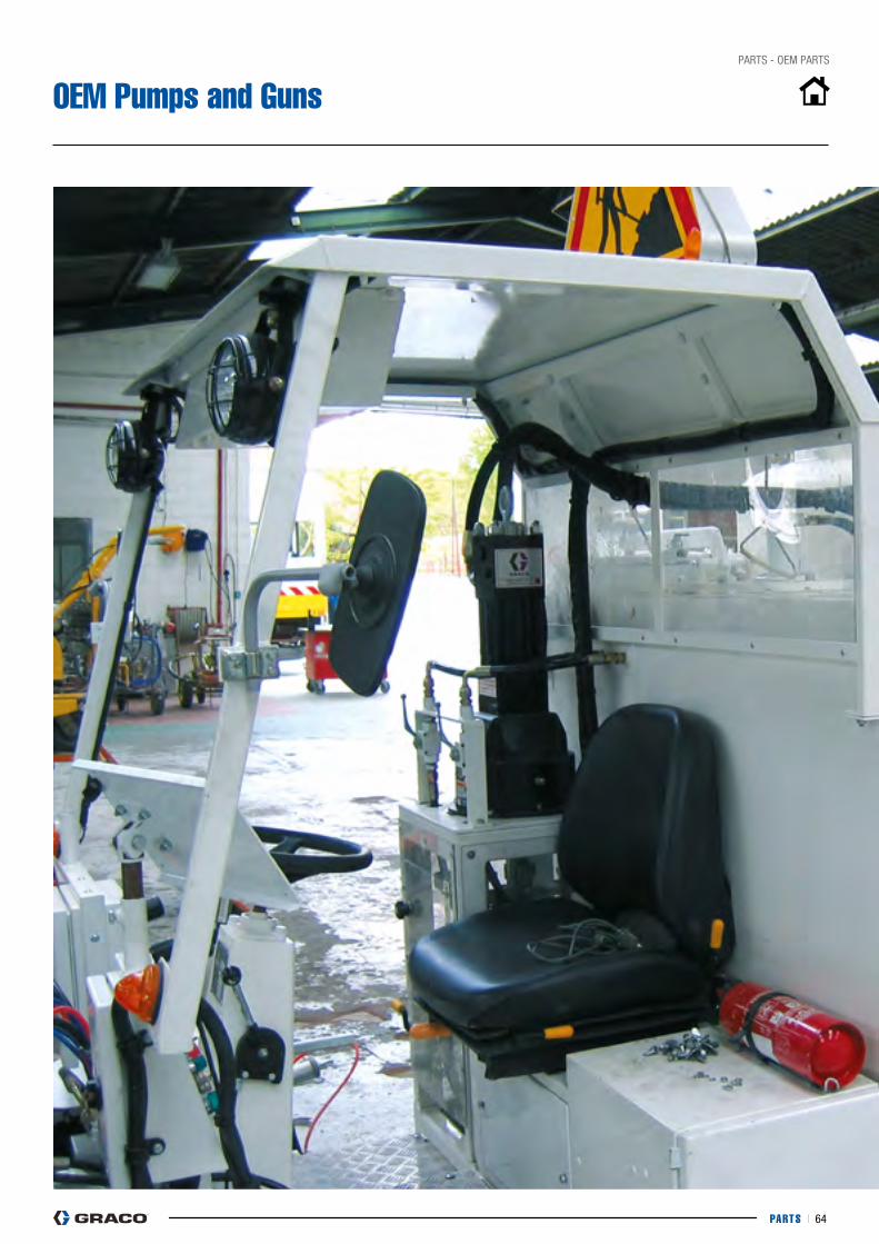
PARTS I 64
pARTS - OEM pARTS
OEM Pumps and Guns
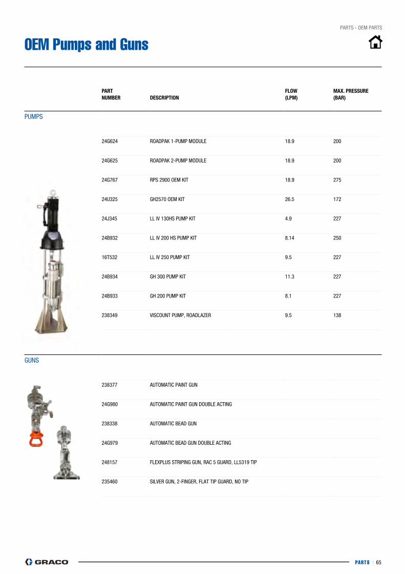
PARTS I 65
pARTS - OEM pARTS
OEM Pumps and Guns
PART nUMBeR DesCRiPTiOn
flOw(lPM)
MAx. PRessURe(BAR)
pUMpS
24G624 ROADpAK 1-pUMp MODULE 18.9 200
24G625 ROADpAK 2-pUMp MODULE 18.9 200
24G767 RpS 2900 OEM KIT 18.9 275
24U325 GH2570 OEM KIT 26.5 172
24j345 LL IV 130HS pUMp KIT 4.9 227
24B932 LL IV 200 HS pUMp KIT 8.14 250
16T532 LL IV 250 pUMp KIT 9.5 227
24B934 GH 300 pUMp KIT 11.3 227
24B933 GH 200 pUMp KIT 8.1 227
238349 VIScOUNT pUMp, ROADLAZER 9.5 138
GUNS
238377 AUTOMATIc pAINT GUN
24G980 AUTOMATIc pAINT GUN DOUBLE AcTING
238338 AUTOMATIc BEAD GUN
24G979 AUTOMATIc BEAD GUN DOUBLE AcTING
248157 FLEXpLUS STRIpING GUN, RAc 5 GUARD, LL5319 TIp
235460 SILVER GUN, 2-FINGER, FLAT TIp GUARD, NO TIp

PARTS I 66
pARTS - TIpS & NOZZLES
LL5 Spray Tips: Creating Laser-Sharp Lines
Graco's linelazer RAC 5 switchTipsSpecially designed for Line Striping Equipment, Graco’s LL5 spray tips create clean and laser-sharp lines with no fuzzy edges. LL5 tips spray heavy waterbase to thin alkyd traffic paint and ensures consistent paint thickness, from edge to edge, less overspray and long-lasting lines.
621
The pump delivers:• paint flow• paint pressure
The tip size tells the pump how hard it must work.
hose
The tip defines:• Spray angle• Spray volume
Understanding Tips
The first digit describes the angle, i.e. 6 = 60°. Multiply first digit by 5 to get the actual fan width when spraying 30 cm away from the wall, i.e. 5 x 5 = 25 cm.
The 2nd and 3rd digits describe the orifice size, i.e. 21 = 0.021".
The secret behind the numbers (All tip specifications are measured 30 cm away from the surface)
Adjusting to the Right Tip Basic rule: when switching tips, adjust to the new fan width and new orifice size. Together. e.g.: 517 - > 619
50°
50°
70°
30°
513
521
717
317
517517
not enough paint? 1. Increase orifice size
2. Increase fan angle
2. Decrease fan angle
0.017" = 1.17 lpm
0.017" = 1.17 lpm
0.013" = 0.7 lpm
0.021" = 1.8 lpm
Too much paint?
PROBleM sOlUTiOns
25cm
25cm
35cm
15cm
1. Reduce orifice size
50°
25cm
SURFAcE
50°
25cm
SURFAcE
SURF
AcE
SURF
AcE
SURF
AcE
SURF
AcE
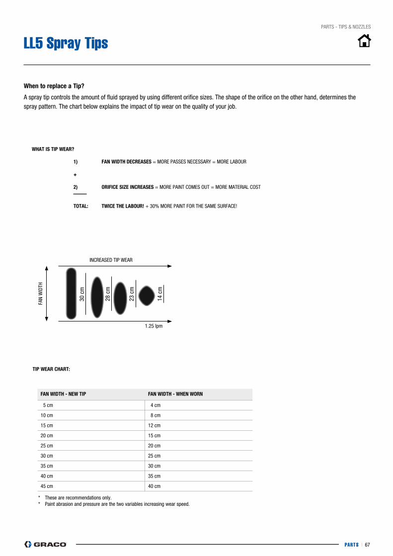
PARTS I 67
pARTS - TIpS & NOZZLES
LL5 Spray Tips
A spray tip controls the amount of fluid sprayed by using different orifice sizes. The shape of the orifice on the other hand, determines the spray pattern. The chart below explains the impact of tip wear on the quality of your job.
30 c
m
28 c
m
23 c
m
14 c
m 1) fAn wiDTh DeCReAses = MORE pASSES NEcESSARy = MORE LABOUR + 2) ORifiCe size inCReAses = MORE pAINT cOMES OUT = MORE MATERIAL cOST
TOTAl: TwiCe The lABOUR! + 30% MORE pAINT FOR THE SAME SURFAcE!
TiP weAR ChART:
* These are recommendations only.* paint abrasion and pressure are the two variables increasing wear speed.
INcREASED TIp WEAR
FAN
WID
TH
fAn wiDTh - new TiP fAn wiDTh - when wORn
05 cm 04 cm
10 cm 08 cm
15 cm 12 cm
20 cm 15 cm
25 cm 20 cm
30 cm 25 cm
35 cm 30 cm
40 cm 35 cm
45 cm 40 cm
1.25 lpm
when to replace a Tip?
whAT is TiP weAR?
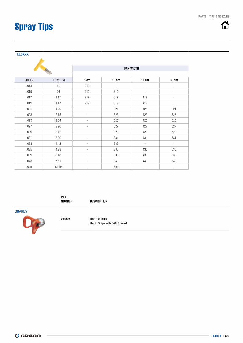
PARTS I 68
pARTS - TIpS & NOZZLES
Spray Tips
LL5XXX
fAn wiDTh
ORIFIcE FLOW LpM 5 cm 10 cm 15 cm 30 cm
.013 .69 213 - - -
.015 .91 215 315 - -
.017 1.17 217 317 417 -
.019 1.47 219 319 419 -
.021 1.79 - 321 421 621
.023 2.15 - 323 423 623
.025 2.54 - 325 425 625
.027 2.96 - 327 427 627
.029 3.42 - 329 429 629
.031 3.90 - 331 431 631
.033 4.42 - 333 - -
.035 4.98 - 335 435 635
.039 6.18 - 339 439 639
.043 7.51 - 343 443 643
.055 12.29 - 355 - -
PART nUMBeR
DesCRiPTiOn
GUARDS
243161 RAc 5 GUARDUse LL5 tips with RAc 5 guard
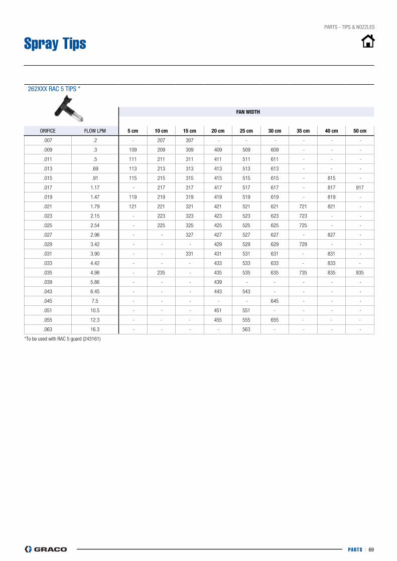
PARTS I 69
pARTS - TIpS & NOZZLES
Spray Tips
262XXX RAc 5 TIpS *
fAn wiDTh
ORIFIcE FLOW LpM 5 cm 10 cm 15 cm 20 cm 25 cm 30 cm 35 cm 40 cm 50 cm
.007 .2 - 207 307 - - - - - -
.009 .3 109 209 309 409 509 609 - - -
.011 .5 111 211 311 411 511 611 - - -
.013 .69 113 213 313 413 513 613 - - -
.015 .91 115 215 315 415 515 615 - 815 -
.017 1.17 - 217 317 417 517 617 - 817 917
.019 1.47 119 219 319 419 519 619 - 819 -
.021 1.79 121 221 321 421 521 621 721 821 -
.023 2.15 - 223 323 423 523 623 723 - -
.025 2.54 - 225 325 425 525 625 725 - -
.027 2.96 - - 327 427 527 627 - 827 -
.029 3.42 - - - 429 529 629 729 - -
.031 3.90 - - 331 431 531 631 - 831 -
.033 4.42 - - - 433 533 633 - 833 -
.035 4.98 - 235 - 435 535 635 735 835 935
.039 5.86 - - - 439 - - - - -
.043 6.45 - - - 443 543 - - - -
.045 7.5 - - - - - 645 - - -
.051 10.5 - - - 451 551 - - - -
.055 12.3 - - - 455 555 655 - - -
.063 16.3 - - - - 563 - - - -
*To be used with RAC 5 guard (243161)
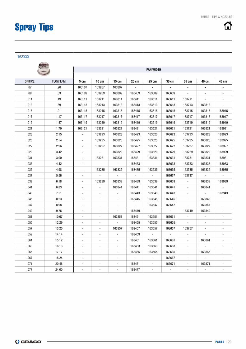
PARTS I 70
pARTS - TIpS & NOZZLES
Spray Tips
163XXX
fAn wiDTh
ORIFIcE FLOW LpM 5 cm 10 cm 15 cm 20 cm 25 cm 30 cm 35 cm 40 cm 45 cm
.07 .20 163107 163207 163307 - - - - - -
.09 .33 163109 163209 163309 163409 163509 163609 - - -
.011 .49 163111 163211 163311 163411 163511 163611 163711 - -
.013 .69 163113 163213 163313 163413 163513 163613 163713 163813 -
.015 .91 163115 163215 163315 163415 163515 163615 163715 163815 163915
.017 1.17 163117 163217 163317 163417 163517 163617 163717 163817 163917
.019 1.47 163119 163219 163319 163419 163519 163619 163719 163819 163919
.021 1.79 163121 163221 163321 163421 163521 163621 163721 163821 163921
.023 2.15 - 163223 163323 163423 163523 163623 163723 163823 163923
.025 2.54 - 163225 163325 163425 163525 163625 163725 163825 163925
.027 2.96 - 163227 163327 163427 163527 163627 163727 163827 163927
.029 3.42 - - 163329 163429 163529 163629 163729 163829 163929
.031 3.90 - 163231 163331 163431 163531 163631 163731 163831 163931
.033 4.42 - - - 163433 - 163633 163733 163833 163933
.035 4.98 - 163235 163335 163435 163535 163635 163735 163835 163935
.037 5.56 - - - - - 163637 163737 - -
.039 6.18 - 163239 163339 163439 163539 163639 - 163839 163939
.041 6.83 - - 163341 163441 163541 163641 - 163841 -
.043 7.51 - - - 163443 163543 163643 - - 163943
.045 8.23 - - - 163445 163545 163645 - 163845 -
.047 8.98 - - - - 163547 163647 - 163847 -
.049 9.76 - - - 163449 - - 163749 163849 -
.051 10.67 - - 163351 163451 163551 163651 - - -
.055 12.29 - - - 163455 163555 163655 - - -
.057 13.20 - - 163357 163457 163557 163657 163757 - -
.059 14.14 - - - 163459 - - - - -
.061 15.12 - - - 163461 163561 163661 - 163861 -
.063 16.13 - - - 163463 163563 163663 - - -
.065 17.17 - - - 163465 163565 163665 - 163865 -
.067 18.24 - - - - - 163667 - - -
.071 20.48 - - - 163471 - 163671 - 163871 -
.077 24.00 - - - 163477 - - - - -
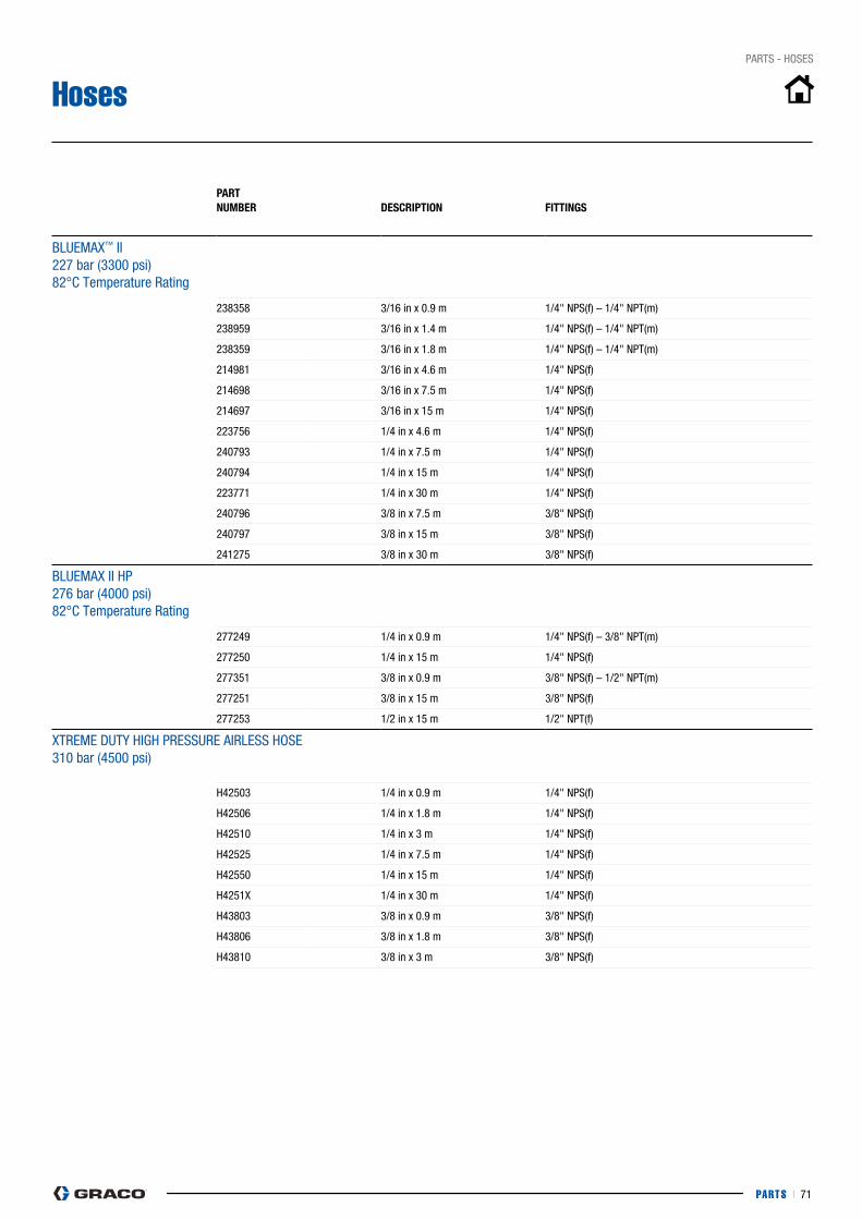
PARTS I 71
pARTS - HOSES
Hoses
PART nUMBeR
DesCRiPTiOn fiTTinGs
BLUEMAX™ II 227 bar (3300 psi) 82°c Temperature Rating
238358 3/16 in x 0.9 m 1/4" NpS(f) – 1/4" NpT(m)
238959 3/16 in x 1.4 m 1/4" NpS(f) – 1/4" NpT(m)
238359 3/16 in x 1.8 m 1/4" NpS(f) – 1/4" NpT(m)
214981 3/16 in x 4.6 m 1/4" NpS(f)
214698 3/16 in x 7.5 m 1/4" NpS(f)
214697 3/16 in x 15 m 1/4" NpS(f)
223756 1/4 in x 4.6 m 1/4" NpS(f)
240793 1/4 in x 7.5 m 1/4" NpS(f)
240794 1/4 in x 15 m 1/4" NpS(f)
223771 1/4 in x 30 m 1/4" NpS(f)
240796 3/8 in x 7.5 m 3/8" NpS(f)
240797 3/8 in x 15 m 3/8" NpS(f)
241275 3/8 in x 30 m 3/8" NpS(f)
BLUEMAX II Hp276 bar (4000 psi) 82°c Temperature Rating
277249 1/4 in x 0.9 m 1/4" NpS(f) – 3/8" NpT(m)
277250 1/4 in x 15 m 1/4" NpS(f)
277351 3/8 in x 0.9 m 3/8" NpS(f) – 1/2" NpT(m)
277251 3/8 in x 15 m 3/8" NpS(f)
277253 1/2 in x 15 m 1/2" NpT(f)
XTREME DUTy HIGH pRESSURE AIRLESS HOSE310 bar (4500 psi)
H42503 1/4 in x 0.9 m 1/4" NpS(f)
H42506 1/4 in x 1.8 m 1/4" NpS(f)
H42510 1/4 in x 3 m 1/4" NpS(f)
H42525 1/4 in x 7.5 m 1/4" NpS(f)
H42550 1/4 in x 15 m 1/4" NpS(f)
H4251X 1/4 in x 30 m 1/4" NpS(f)
H43803 3/8 in x 0.9 m 3/8" NpS(f)
H43806 3/8 in x 1.8 m 3/8" NpS(f)
H43810 3/8 in x 3 m 3/8" NpS(f)
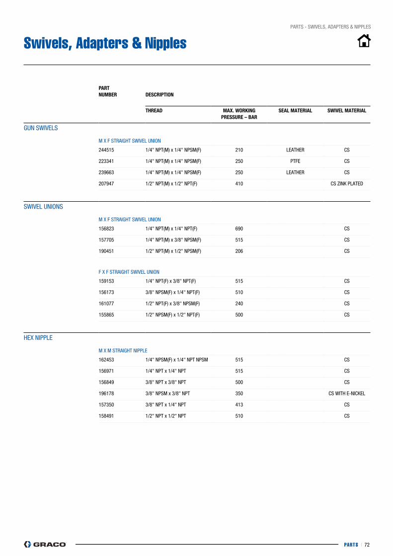
PARTS I 72
pARTS - SWIVELS, ADApTERS & NIppLES
Swivels, Adapters & Nipples
PART nUMBeR
DesCRiPTiOn
ThReAD MAx. wORkinG PRessURe – BAR
seAl MATeRiAl swiVel MATeRiAl
GUN SWIVELS M X F STRAIGHT SWIVEL UNION
244515 1/4" NpT(M) x 1/4" NpSM(F) 210 LEATHER cS
223341 1/4" NpT(M) x 1/4" NpSM(F) 250 pTFE cS
239663 1/4" NpT(M) x 1/4" NpSM(F) 250 LEATHER cS
207947 1/2" NpT(M) x 1/2" NpT(F) 410 cS ZINK pLATED
SWIVEL UNIONS M X F STRAIGHT SWIVEL UNION
156823 1/4" NpT(M) x 1/4" NpT(F) 690 cS
157705 1/4" NpT(M) x 3/8" NpSM(F) 515 cS
190451 1/2" NpT(M) x 1/2" NpSM(F) 206 cS
F X F STRAIGHT SWIVEL UNION
159153 1/4" NpT(F) x 3/8" NpT(F) 515 cS
156173 3/8" NpSM(F) x 1/4" NpT(F) 510 cS
161077 1/2" NpT(F) x 3/8" NpSM(F) 240 cS
155865 1/2" NpSM(F) x 1/2" NpT(F) 500 cS
HEX NIppLE M X M STRAIGHT NIppLE
162453 1/4" NpSM(F) x 1/4" NpT NpSM 515 cS
156971 1/4" NpT x 1/4" NpT 515 cS
156849 3/8" NpT x 3/8" NpT 500 cS
196178 3/8" NpSM x 3/8" NpT 350 cS WITH E-NIcKEL
157350 3/8" NpT x 1/4" NpT 413 cS
158491 1/2" NpT x 1/2" NpT 510 cS

PARTS I 73
pARTS - SWIVELS, ADApTERS & NIppLES
Swivels, Adapters & Nipples
PART nUMBeR
DesCRiPTiOn
ThReAD MAx. wORkinG PRessURe – BAR
seAl MATeRiAl swiVel MATeRiAl
REDUcING NIppLES M X M
191872 1/8" NpT x 1/4" NpSM 345 cS
165274 1/4" NpT x 11/16" - 27 UNS 345 cS
164856 3/8" NpT x 1/4" NpT 550 SS
164672 3/8" NpT x 1/4" NpSM 413 cS
196177 3/8" NpT x 1/4" NpSM 415 cS WITH E-NIcKEL
161800 3/4" NpT x 3/8" NpSM 275 cS
196142 3/4" NpT x 1/2" NpT 345 cS
158979 1/2" NpT x 3/8" NpT 375 cS WITH E-NIcKEL
159239 1/2" NpT x 3/8" NpT 510 cS
ADApTERS M X F
244825 1/4" NpT, 7/8" - 14 UNp 230 cS
104969 1/2" NpT x 3/4" NpT 275 cS
181085 7/8" NpT - 14 UNF, 11/16" NpT - 16 UNEF metric gun to Graco guard
345 cS
181084 7/8" - 14 UNF, 3/4" NpT 345 cS
164120 11/16" - 16 UNEF, 3/4" NpT 7/8" - 14 UNF-2B Graco gun to metric guard
345 cS
159841 1/4" NpT(F) x 3/8" NpT(M) 345 cS
pIpE TEES F X F X M
106228 2 X 1/4" NpT(F) x 1/4" NpT(M) 210 BRASS
108673 2 X 3/8" NpT(F) x 3/8" NpT(M) 275 SS
111337 2 X 3/4" NpT(F) x 3/4" NpT(M) 275 cS
BALL VALVES
239280 1/4" NpT(MBE) 350 FLUOELASTOMER
238694 3/8" NpT(MBE) 350 pTFE / SS
223522 1/4" NpT(M) x DRILLED pLUG 350 FLUOELASTOMER
224441 3/8" NpT(M) x DRILLED pLUG 350 FLUOELASTOMER
238967 3/8" NpT(M) (MBE) 350 pTFE WITH pEEK SEAT
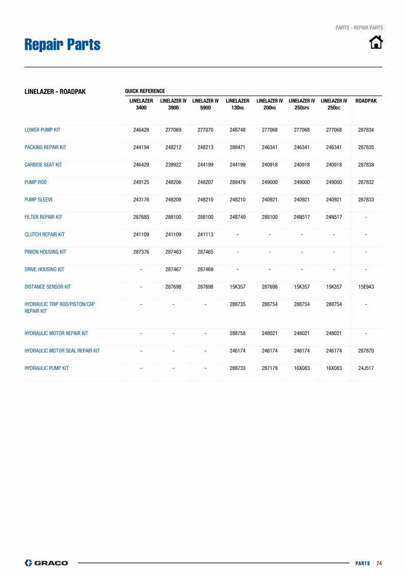
PARTS I 74
pARTS - REpAIR pARTS
Repair Parts
linelAzeR - ROADPAk QUiCk RefeRenCe
linelAzeR 3400
linelAzeR iV 3900
linelAzeR iV 5900
linelAzeR 130hs
linelAzeR iV 200hs
linelAzeR iV 250sPs
linelAzeR iV 250DC
ROADPAk
LOWER pUMp KIT 246428 277069 277070 24B748 277068 277068 277068 287834
pAcKING REpAIR KIT 244194 248212 248213 288471 246341 246341 246341 287835
cARBIDE SEAT KIT 246429 239922 244199 244199 240918 240918 240918 287838
pUMp ROD 249125 248206 248207 288479 249000 249000 249000 287832
pUMp SLEEVE 243176 248209 248210 248210 240921 240921 240921 287833
FILTER REpAIR KIT 287685 288100 288100 24B749 288100 24N517 24N517 -
cLUTcH REpAIR KIT 241109 241109 241113 - - - - -
pINION HOUSING KIT 287376 287463 287465 - - - - -
DRIVE HOUSING KIT - 287467 287469 - - - - -
DISTANcE SENSOR KIT - 287698 287698 15K357 287698 15K357 15K357 15E943
HyDRAULIc TRIp ROD/pISTON/cAp REpAIR KIT
- - - 288735 288754 288754 288754 -
HyDRAULIc MOTOR REpAIR KIT - - - 288758 248021 248021 248021 -
HyDRAULIc MOTOR SEAL REpAIR KIT - - - 246174 246174 246174 246174 287870
HyDRAULIc pUMp KIT - - - 288733 287179 16X083 16X083 24j517
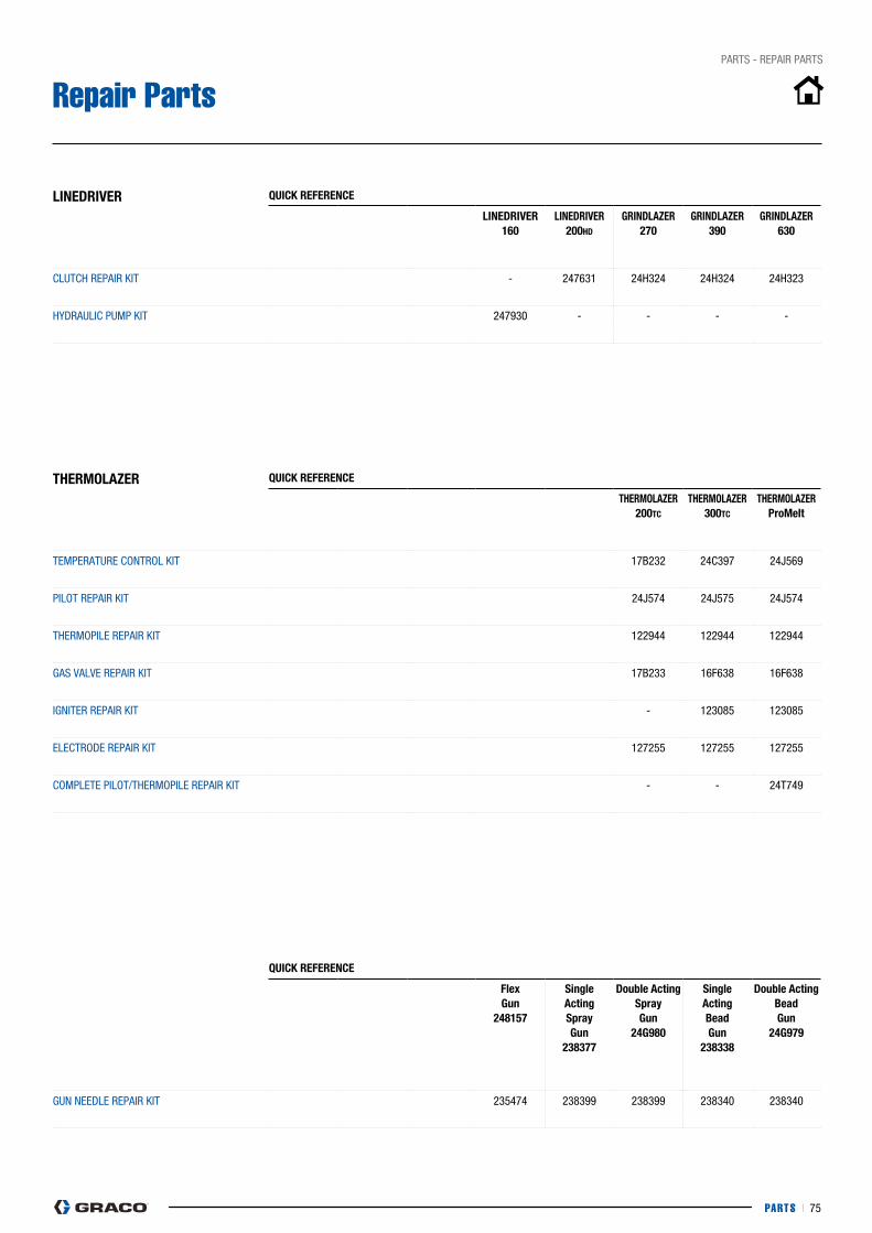
PARTS I 75
pARTS - REpAIR pARTS
Repair Parts
lineDRiVeR QUiCk RefeRenCe
lineDRiVeR 160
lineDRiVeR 200hD
GRinDlAzeR 270
GRinDlAzeR 390
GRinDlAzeR 630
cLUTcH REpAIR KIT - 247631 24H324 24H324 24H323
HyDRAULIc pUMp KIT 247930 - - - -
TheRMOlAzeR QUiCk RefeRenCe
TheRMOlAzeR 200TC
TheRMOlAzeR 300TC
TheRMOlAzeR ProMelt
TEMpERATURE cONTROL KIT 17B232 24c397 24j569
pILOT REpAIR KIT 24j574 24j575 24j574
THERMOpILE REpAIR KIT 122944 122944 122944
GAS VALVE REpAIR KIT 17B233 16F638 16F638
IGNITER REpAIR KIT - 123085 123085
ELEcTRODE REpAIR KIT 127255 127255 127255
cOMpLETE pILOT/THERMOpILE REpAIR KIT - - 24T749
QUiCk RefeRenCe
flex Gun
248157
single Actingspray Gun
238377
Double Actingspray Gun
24G980
single ActingBead Gun
238338
Double ActingBead Gun
24G979
GUN NEEDLE REpAIR KIT 235474 238399 238399 238340 238340

WARRANTY I 76
WARRANTY

WARRANTY I 77
WARRANTY
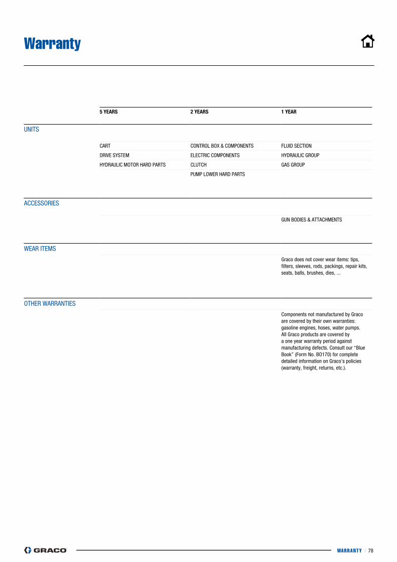
WARRANTY I 78
Warranty
5 YeARs 2 YeARs 1 YeAR
UNITS
cART cONTROL BOX & cOMpONENTS FLUID SEcTION
DRIVE SySTEM ELEcTRIc cOMpONENTS HyDRAULIc GROUp
HyDRAULIc MOTOR HARD pARTS cLUTcH GAS GROUp
pUMp LOWER HARD pARTS
AccESSORIES
GUN BODIES & ATTAcHMENTS
WEAR ITEMS
Graco does not cover wear items: tips, filters, sleeves, rods, packings, repair kits, seats, balls, brushes, dies, ...
OTHER WARRANTIES
components not manufactured by Graco are covered by their own warranties: gasoline engines, hoses, water pumps.All Graco products are covered by a one year warranty period against manufacturing defects. consult our “Blue Book” (Form No. BO170) for complete detailed information on Graco’s policies (warranty, freight, returns, etc.).

WARRANTY I 79
Notes
©2015 Graco BVBA 300720ENEU Rev.A 03/15 printed in Europe.All other brand names or marks are used for identification purposes and are trademarks of their respective owners.
ABOUT GRACO
GRACO lOCATiOns
europe+32 89 770 700
FAx +32 89 770 777www.GRACO.COM
Founded in 1926, Graco is a world leader in fluid handling systems and components. Graco products move, measure, control, dispense and apply a wide range of fluids and viscous materials used in vehicle lubrication, commercial and industrial settings.
The company’s success is based on its unwavering commitment to technical excellence, world-class manufacturing and unparalleled customer service. Working closely with qualified distributors, Graco offers systems, products and technology that set the quality standard in a wide range of fluid handling solutions. Graco provides equipment for spray finishing, protective coating, paint circulation, lubrication, and dispensing sealants and adhesives, along with power application equipment for the contractor industry. Graco’s ongoing investment in fluid management and control will continue to provide innovative solutions to a diverse global market.
Graco is certified ISO 9001.
MAILING ADDRESSp.O. Box 1441Minneapolis, MN 55440-1441Tel: 612-623-6000Fax: 612-623-6777
AMeRiCAsMINNESOTAWorldwide HeadquartersGraco Inc.88-11th Avenue N.E.Minneapolis, MN 55413
CHINAGraco Hong Kong Ltd.Shanghai Representative OfficeBuilding 7 1029 Zhongshan Road South Huangpu DistrictShanghai 200011The people’s Republic of chinaTel: 86 21 649 50088Fax: 86 21 649 50077
KOREAGraco Korea Inc.Shinhan Bank Building4th Floor #1599Gwanyang-Dong, Dongan-Ku,Anyang-si, Korea 431-060Tel: 82 31 476 9400Fax: 82 31 476 9801
eUROPeBELGIUMEuropean HeadquartersGraco BVBAIndustrieterrein-Oude BundersSlakweidestraat 313630 Maasmechelen, BelgiumTel: 32 89 770 700Fax: 32 89 770 777
All written and visual data contained in this document are based on the latest product information available at the time of publication. Graco reserves the right to make changes at any time without notice.
AsiA PACifiCAUSTRALIAGraco Australia pty Ltd.Suite 17, 2 Enterprise Drive Bundoora, Victoria 3083AustraliaTel: 61 3 9468 8500Fax: 61 3 9468 8599
INDIAGraco Hong Kong Ltd. India Liaison OfficeRoom 432, Augusta point Regus Business centre 53 Golf course Road Gurgaon, Haryana India 122001 Tel: 91 124 435 4208Fax: 91 124 435 4001
JAPANGraco K.K.1-27-12 HayabuchiTsuzuki-kuyokohama city, japan 2240025Tel: 81 45 593 7300Fax: 81 45 593 7301