GRAAD 12 NATIONAL SENIOR...
15
Copyright reserved Please turn over MARKS: 200 TIME: 3 hours This question paper consists of 13 pages and a 2-page formula sheet. ELECTRICAL TECHNOLOGY FEBRUARY/MARCH 2015 NATIONAL SENIOR CERTIFICATE GRAAD 12 GRADE 12 *elctdm*
Transcript of GRAAD 12 NATIONAL SENIOR...

Copyright reserved Please turn over
MARKS: 200 TIME: 3 hours
This question paper consists of 13 pages and a 2-page formula sheet.
ELECTRICAL TECHNOLOGY
FEBRUARY/MARCH 2015
NATIONAL SENIOR CERTIFICATE
GRAAD 12
GRADE 12
*elctdm*

Electrical Technology 2 DBE/Feb.–Mar. 2015 NSC
Copyright reserved Please turn over
INSTRUCTIONS AND INFORMATION 1. 2. 3. 4. 5. 6. 7. 8. 9.
This question paper consists of SEVEN questions. Answer ALL the questions. Sketches and diagrams must be large, neat and fully labelled. Show ALL calculations and round off correctly to TWO decimal places. Number the answers correctly according to the numbering system used in this question paper. You may use a non-programmable calculator. Show the units for all answers of calculations. A formula sheet is provided at the end of this question paper. Write neatly and legibly.
Electrical Technology 3 DBE/Feb.–Mar. 2015 NSC
Copyright reserved Please turn over
QUESTION 1: OCCUPATIONAL HEALTH AND SAFETY 1.1 State TWO unsafe acts that may lead to an electric shock in a workshop. (2) 1.2 State THREE safety procedures that should be followed when a person is
being electrocuted.
(3) 1.3 Human rights and work ethics are principles that are important to all
South Africans. Discuss how you would promote these principles with reference to gender.
(2) 1.4 State THREE considerations when conducting a risk analysis to prevent
accidents in an electrical technology workshop.
(3) [10] QUESTION 2: THREE-PHASE AC GENERATION 2.1 State TWO advantages of three-phase power generation over single-phase
power generation.
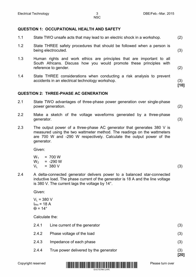
(2) 2.2 Make a sketch of the voltage waveforms generated by a three-phase
generator.
(3) 2.3 The output power of a three-phase AC generator that generates 380 V is
measured using the two wattmeter method. The readings on the wattmeters are 700 W and -290 W respectively. Calculate the output power of the generator.
Given:
W1 = 700 W W2 = -290 W VL = 380 V (3) 2.4 A delta-connected generator delivers power to a balanced star-connected
inductive load. The phase current of the generator is 18 A and the line voltage is 380 V. The current lags the voltage by 14°.
Given:
VL = 380 V IPH = 18 A Ɵ = 14°
Calculate the: 2.4.1 Line current of the generator (3) 2.4.2 Phase voltage of the load (3) 2.4.3 Impedance of each phase (3) 2.4.4 True power delivered by the generator (3) [20]
Electrical Technology 4 DBE/Feb.–Mar. 2015 NSC
Copyright reserved Please turn over
QUESTION 3: THREE-PHASE TRANSFORMERS 3.1 Name TWO types of transformer constructions. (2) 3.2 Explain the purpose of the oil in which the transformer core and windings are
immersed.
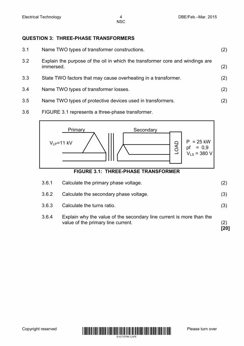
(2) 3.3 State TWO factors that may cause overheating in a transformer. (2) 3.4 Name TWO types of transformer losses. (2) 3.5 Name TWO types of protective devices used in transformers. (2) 3.6 FIGURE 3.1 represents a three-phase transformer.
FIGURE 3.1: THREE-PHASE TRANSFORMER 3.6.1 Calculate the primary phase voltage. (2) 3.6.2 Calculate the secondary phase voltage. (3) 3.6.3 Calculate the turns ratio. (3) 3.6.4 Explain why the value of the secondary line current is more than the
value of the primary line current.
(2) [20]
VLP=11 kV
LOA
D
VLS = 380 V
Primary Secondary
P = 25 kW pf = 0,9

Electrical Technology 5 DBE/Feb.–Mar. 2015 NSC
Copyright reserved Please turn over
QUESTION 4: THREE-PHASE MOTORS AND STARTERS 4.1 Name TWO parts of a three-phase induction motor. (2) 4.2 State TWO advantages of a three-phase induction motor over a single-phase
induction motor.
(2) 4.3 The nameplate of a three-phase induction motor contains specific information
about that motor. List THREE key motor features that would appear on the nameplate.
(3)
4.4 A three-phase induction motor is connected across a 380 V/60 Hz supply.
The motor has a total of 12 poles per phase and a per unit slip of 0,04.
Given:
VL = 380 V f = 60 Hz p = 6 Slip = 0,04 Calculate the: 4.4.1 Synchronous speed (3) 4.4.2 Rotor speed (3) 4.5 Explain why it is important to carry out a mechanical inspection on an
electrical motor before it is energised.
(2) 4.6 State TWO electrical inspections that must be carried out on an electrical
motor before it is energised.
(2) 4.7 Explain the function of an overload unit in a motor starter. (3)

Electrical Technology 6 DBE/Feb.–Mar. 2015 NSC
Copyright reserved Please turn over
4.8 FIGURE 4.1 represents the control circuit of a star-delta starter.
FIGURE 4.1: CONTROL CIRCUIT OF A STAR-DELTA STARTER 4.8.1 State the function of a star-delta starter. (1) 4.8.2 State the mode the motor will be connected in when running at full
load.
(1) 4.8.3 Explain the function of the contacts Retain (Hold in) MC1. (3) 4.8.4 State, with a reason, what would happen to contact T (N/C) when the
timer contactor is energised.
(2) 4.8.5 Describe the interlocking that prevents the star and delta contactors
from being energised at the same time.
(6) 4.9 A three-phase delta-connected motor draws a current of 12 A when
connected to a 380 V/50 Hz supply. The motor has a power factor of 0,8 and an efficiency of 90%.
Given:
VL = 380 V IL = 12 A f = 50 Hz Cos ɸ = 0,8 ŋ = 90% 4.9.1 Calculate the active power of the motor at full load. (3) 4.9.2 Explain what would happen to the active power of the motor if the
efficiency of the motor is improved.
(1) 4.9.3 State the relationship between the line current and the phase current
of the motor.
(1) 4.9.4 Explain what would happen to the current drawn by the motor if the
power factor of the motor is improved.
(2) [40]
O/L
STOP
START
MC1 (N/O)
Retain (Hold in) MC1
T (N/C) T (N/O)
MC3 (N/C)
MC2 (N/C)
MC2 Y
MC3
Δ T
MC1
N
L

Electrical Technology 7 DBE/Feb.–Mar. 2015 NSC
Copyright reserved Please turn over
QUESTION 5: RLC 5.1 Describe ONE practical method of obtaining resonant frequency in a parallel
RLC circuit.
(3) 5.2 Name ONE method that could be used to improve a poor power factor. (1) 5.3 A parallel RLC circuit is at resonant frequency. Describe what would happen
to the current flow if the frequency is decreased below resonant frequency.
(3) 5.4 Study the circuit in FIGURE 5.1 below and answer the questions that follow.
FIGURE 5.1: RLC SERIES CIRCUIT Calculate the: 5.4.1 Resonant frequency (3) 5.4.2 Total current flowing through the circuit at resonance (3) 5.4.3 Q-factor of the circuit (4) 5.4.4 The capacitance of the capacitor required for the circuit to be at
resonance if the frequency of the supply in FIGURE 5.1 is constant at 1 kHz and the inductance is also constant
(3) [20]
VS = 240 V
L = 0,2 mH C = 160 µF R = 30 Ω

Electrical Technology 8 DBE/Feb.–Mar. 2015 NSC
Copyright reserved Please turn over
QUESTION 6: LOGIC
6.1 FIGURE 6.1 represents the block diagram of a PLC system.
FIGURE 6.1: PLC SYSTEM 6.1.1 Explain the function of the input interface. (3) 6.1.2 Name TWO components that may be connected to the input
interface.
(2) 6.1.3 Name TWO electronic devices, other than a relay, that could be
connected to the output interface.
(2) 6.1.4 Describe the THREE steps that make up the programming scan
cycle of a PLC.
(6)

Electrical Technology 9 DBE/Feb.–Mar. 2015 NSC
Copyright reserved Please turn over
6.2 FIGURE 6.2 represents a sequence control diagram.
FIGURE 6.2: SEQUENCE CONTROL CIRCUIT 6.2.1 Draw and label the ladder logic diagram of the control circuit using
the labels in FIGURE 6.2.
(6) 6.2.2 Use a Karnaugh map to simplify the expression below:
C BA C BA C B A C B A X +++=
(6) 6.2.3 Using Boolean algebra, simplify the expression below.
C B A C BA C BA C B A X +++=
(7) 6.2.4 Give ONE example, with an explanation, where a set-reset PLC
programming function could be used in industry.
(3) 6.2.5 Explain the advantage of using an additional emergency stop switch
in a PLC system.
(3) 6.3 Explain how an on-delay timer operates. (2) [40]
C1(Y0)
Start button 2(X5)
Overload 1 (X0)
Stop button 1 (X2)
Contactor 1(Y0)
Start button 1 (X4) C2(Y1)
Contactor 2 (Y1)
Overload 2 (X1)
Stop button 2 (X3)
C1(Y0)

Electrical Technology 10 DBE/Feb.–Mar. 2015 NSC
Copyright reserved Please turn over
QUESTION 7: AMPLIFIERS
7.1 Define a basic 741 operational amplifier device. (3)
7.2 Describe the term infinite bandwidth with reference to an ideal operational amplifier.
(2)
7.3 State TWO ideal characteristics of an operational amplifier other than infinite bandwidth.
(2)
7.4 Describe the following terms with reference to operational amplifiers:
7.4.1 Negative feedback (3) 7.4.2 Positive feedback (3)
7.5 State TWO advantages of negative feedback. (2)
7.6 Refer to FIGURE 7.1.
FIGURE 7.1: OPERATIONAL AMPLIFIER
Redraw the inputs shown and then draw the output of the ideal operational amplifier.
(3)
7.7 FIGURE 7.2 is a non-inverting voltage comparator.
FIGURE 7.2: NON-INVERTING VOLTAGE COMPARATOR
7.7.1 Draw the output voltage wave form if the reference voltage is set at 0 V.
(3)
7.7.2 State ONE application of the operational amplifier. (1)
V
Vin
Vout
0 V
Reference voltage
Rin
V1
V2
Vout
+1
-1
0
+1
-1
0

Electrical Technology 11 DBE/Feb.–Mar. 2015 NSC
Copyright reserved Please turn over
7.8 FIGURE 7.3 is an operational amplifier circuit.
FIGURE 7.3: OPERATIONAL AMPLIFIER CIRCUIT 7.8.1 Identify the type of operational amplifier circuit in FIGURE 7.3. (1) 7.8.2 Redraw the given input signal and then draw the output signal on the
same set of axes. (2)
7.8.3 Calculate the voltage gain of the amplifier. (3) 7.8.4 Calculate the peak output voltage. (3) 7.8.5 Explain how the voltage gain of the operational amplifier will change if
the value of the resistor Rf was decreased.
(2) 7.8.6 Explain the function of Rin. (2) 7.9 Give ONE reason why operational amplifiers are used between stages of
complex circuits. (2)
Rf = 12 kΩ Vin= 3 V
Vout
Rin = 3 kΩ

Electrical Technology 12 DBE/Feb.–Mar. 2015 NSC
Copyright reserved Please turn over
7.10 FIGURE 7.4 is an operational amplifier connected in the configuration of an
integrator circuit.
FIGURE 7.4: INTEGRATOR OPERATIONAL AMPLIFIER 7.10.1 Draw the output wave form of the circuit. (3) 7.10.2 Describe the specific function that Rin and C perform. (3)
C
Rin
Vin Vout
+V
0V
-V
Electrical Technology 13 DBE/Feb.–Mar. 2015 NSC
Copyright reserved
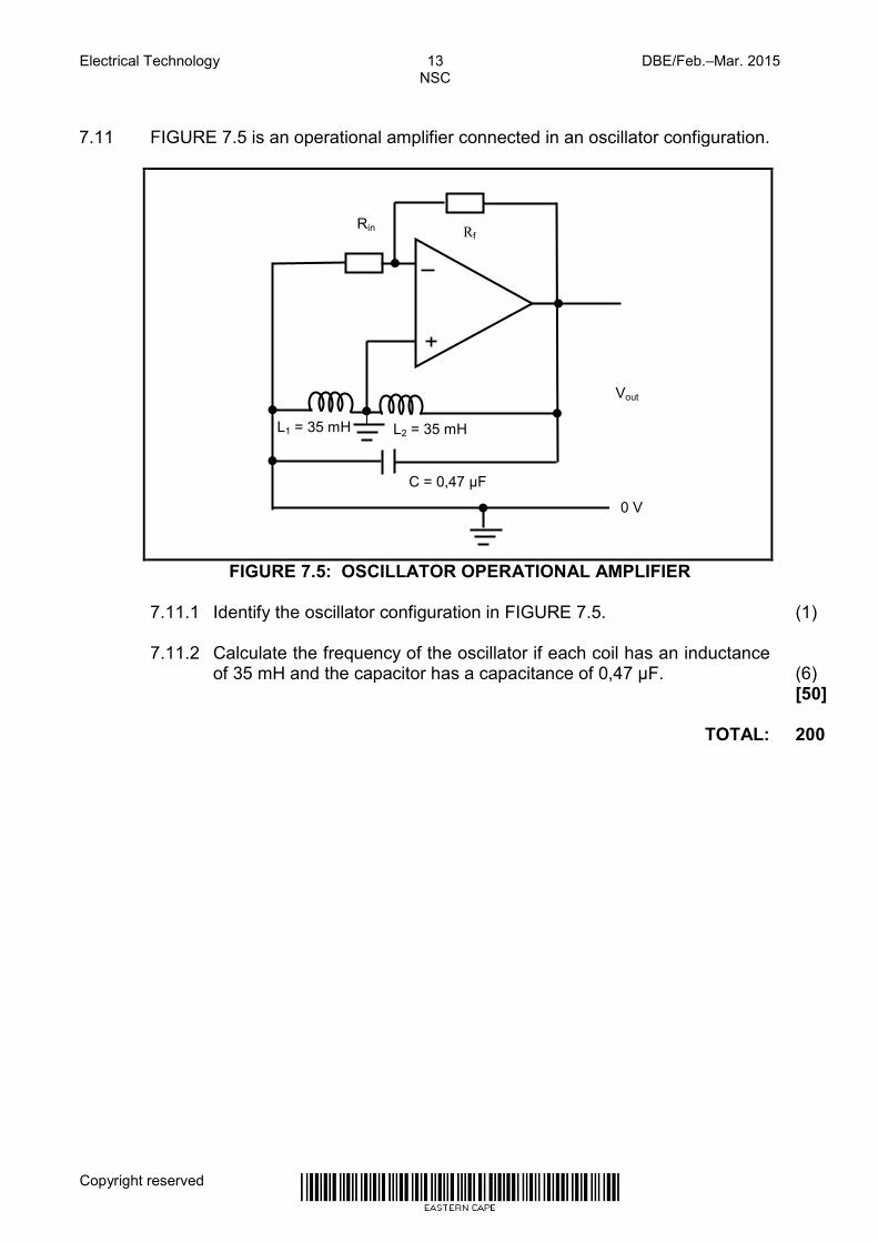
7.11 FIGURE 7.5 is an operational amplifier connected in an oscillator configuration.
FIGURE 7.5: OSCILLATOR OPERATIONAL AMPLIFIER 7.11.1 Identify the oscillator configuration in FIGURE 7.5. (1) 7.11.2 Calculate the frequency of the oscillator if each coil has an inductance
of 35 mH and the capacitor has a capacitance of 0,47 µF.
(6) [50] TOTAL: 200
Rin
Vout
Rf
C = 0,47 µF
L2 = 35 mH
0 V
L1 = 35 mH

Electrical Technology DBE/Feb.–Mar. 2015 NSC
Copyright reserved
FORMULA SHEET
THREE-PHASE AC GENERATION Star
PHL V 3V =
PHL II = Delta
PHL I 3I =
PHL VV =
CosθIV3P LL ×=
LL I V 3=S
θSin I V 3=Q LL
SP
=Cosθ
PH
PHPH I
VZ =
Two wattmeter method 21T PPP +=
THREE-PHASE TRANSFORMERS Star
PHL V 3V =
PHL II = Delta
PHL I 3I =
PHL VV =
θ Cos I V 3=P LL
LL I V 3=S
θSin I V 3=Q LL
SP
=Cosθ
PH(p)
PH(s)
S
P
PH(s)
PH(p)
II
NN
VV
==
RLC CIRUITS
fLπ2=XL
fcπ21
=Xc
(LC)2π1fr =
Series
LCRT I=I=I=I
( )2CL
2 X~XRZ −+=
LL X I=V
CC X I=V
ZI=VT
( )2CL
2RT V~VVV −+=
ZV
=I TT
ZR
=Cosθ
T
R
VV
=Cosθ
RX
Q L=
Parallel LCRT V=V=V=V
RV
=I RR
C
CC X
V=I
L
LL X
V=I
( )2CL
2RT I~III −+=
T
R
II
=Cosθ
RX
Q L=

Electrical Technology DBE/Feb.–Mar. 2015 NSC
Copyright reserved
THREE-PHASE MOTORS AND STARTERS Star
PHL V 3V =
PHL II = Delta
PHL I 3I =
PHL VV = Power
θ Cos I V 3=P LL
LL I V 3=S
θSin I V 3=Q LL
( )in
in
PlossesPη Efficiency −
=
Speed
pf×60
=ns
s
rsPer Unit n
nnSlip
−=
( )Per Unitsr S1nn −=
%100n
nnslip %
s
rs ×−
=
OPERATIONAL AMPLIFIERS
amp op inverting RR
VV
AGain in
f
in
outV
−=−=
amp op inverting-non RR
1VV
AGain in
f
in
outV +==
oscillator-Hartley LC2π
1f r =
oscillatorshift -phase-RC 6RC2π1f RC =
)....V+V+(V=V N21Out