GR MAG & EM GEOPH SUR OF THE CASTLEWOOD L CL BLK
27
NORTHGATE EXPLORATION LIMITED 42E ' 3NE " 3 ' 2 ' 9H9 CASTLEWOOD LAKE SUITE 2701, P. O. BOX 143, 1 FIRST CANADIAN PLACE, TORONTO, CANADA MBX 1C7 - TELEPHONE (416) 362-6683 - TELEX 06-217766 010 GROUND MAGNETIC 6 ELECTROMAGNETIC GEOPHYSICAL SURVEYS OF THE CASTLEWOOD LAKE CLAIM BLOCK THUNDER BAY MINING DIVISION NTS 42-E-13 RECEIVED iir,.; 21986 MIWNG LANDS SECTION Toronto, Ontario May 1986 T. R. Atkins, B.Se. G. Harper, Ph.D.
Transcript of GR MAG & EM GEOPH SUR OF THE CASTLEWOOD L CL BLK

NORTHGATE EXPLORATION LIMITED 42E ' 3NE"3 ' 2 ' 9H9 CASTLEWOOD LAKE
SUITE 2701, P. O. BOX 143, 1 FIRST CANADIAN PLACE, TORONTO, CANADA MBX 1C7 - TELEPHONE (416) 362-6683 - TELEX 06-217766
010
GROUND MAGNETIC 6 ELECTROMAGNETIC
GEOPHYSICAL SURVEYS
OF THE
CASTLEWOOD LAKE CLAIM BLOCK
THUNDER BAY MINING DIVISION
NTS 42-E-13
RECEIVEDiir,.; 21986
MIWNG LANDS SECTION
Toronto, Ontario
May 1986
T. R. Atkins, B.Se.
G. Harper, Ph.D.

TABLE OF42E13N6W931 2.9149 CASTLEWOOD LAKE 010C
SECTION PACE NO.
1.0 INTRODUCTION 1
2.0 LOCATION AND ACCESS 2
3.0 PROPERTY 2
1.0 INFRASTRUCTURE AND ECONOMIC ACTIVITY 2
5.0 TOPOGRAPHY 5
6.0 PREVIOUS GEOLOGICAL WORK 6
7.0 REGIONAL GEOLOGY 7
8.0 GEOPHYSICAL SURVEYS 8
8.1 GENERAL 8
8.2 MAGNETIC SURVEY 8
8.3 MAGNETIC SURVEY INTERPRETATION 9
8.4 ELECTROMAGNETIC SURVEY 10
8.5 ELECTROMAGNETIC CONDUCTOR INTERPRETATION 11
9.0 CONCLUSION 13
10.0 RECOMMENDATIONS 13
II.O REFERENCES 14
12.0 CERTIFICATION OF CREDENTIALS 15
LIST OF TABLE, FIGURE, MAPS
TABLE l - CASTLEWOOD LAKE AREA CLAIMS
FIGURE l - LOCATION MAP
MAPS
MAGNETIC SURVEY MAP
ELECTROMAGNETIC SURVEY MAP
3
4
(In Back Pocket)
(In Back Pocket)

1.0 INTRODUCTION
Northgate Exploration Ltd. holds a block of 14 contiguous claims
northwest of Castlewood Lake, 30 kms north-northwest of Jellicoe,
Ontario. They were staked in April 1985 to cover an area of
anomalous rock geochemistry discovered by a regional survey in
1984. Initial field investigations of the claims were made in August
1985. A total of 19.336 km of picket lines and 2.963 kms of base
line were cut by Mid-Canada Exploration Ltd. covering all 14 claims
of the Castlewood Lake property. The baseline is oriented at 120 0
with perpendicular cross lines at 100 m intervals and picketed every
25 m. Subsequently the geological mapping and VLF-EM and
magnetometer geophysical surveys were performed by Northgate Project
Geologist Tom Atkins and field assistants Lyndon Majid and Terry
Sinclair respectively. The results of the geophysical surveys are
presented in this report. Reference is made to the companion report
which describes the results of the line cutting and geological mapping.
- 2 -
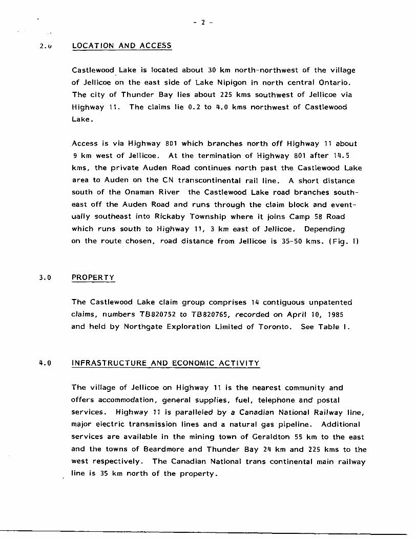
2.u LOCATION AND ACCESS
Castlewood Lake is located about 30 km north-northwest of the village
of Jellicoe on the east side of Lake Nipigon in north central Ontario.
The city of Thunder Bay lies about 225 kms southwest of Jellicoe via
Highway 11. The claims lie 0.2 to 4.0 kms northwest of Castlewood
Lake.
Access is via Highway 801 which branches north off Highway 11 about
9 km west of Jellicoe. At the termination of Highway 801 after 14.5
kms, the private Auden Road continues north past the Castlewood Lake
area to Auden on the CN transcontinental rail line. A short distance
south of the Onaman River the Castlewood Lake road branches south-
east off the Auden Road and runs through the claim block and event
ually southeast into Rickaby Township where it joins Camp 58 Road
which runs south to Highway 11, 3 km east of Jellicoe. Depending
on the route chosen, road distance from Jellicoe is 35-50 kms. (Fig. l)
3.0 PROPERTY
The Castlewood Lake claim group comprises 14 contiguous unpatented
claims, numbers TB820752 to TB820765, recorded on April 10, 1985
and held by Northgate Exploration Limited of Toronto. See Table l.
4.0 INFRASTRUCTURE AND ECONOMIC ACTIVITY
The village of Jellicoe on Highway 11 is the nearest community and
offers accommodation, general supplies, fuel, telephone and postal
services. Highway 11 is paralleled by a Canadian National Railway line,
major electric transmission lines and a natural gas pipeline. Additional
services are available in the mining town of Geraldton 55 km to the east
and the towns of Beardmore and Thunder Bay 24 km and 225 kms to the
west respectively. The Canadian National trans continental main railway
line is 35 km north of the property.

- 3 -
TABLE l
CASTLEWOOD LAKE AREA CLAIMS
Claim No. Recording Date
TB-820752
TB-820753
TB-820754
TB-820755
TB-820756
TB-820757
TB-820758
TB-820759
TB-820760
TB-820761
TB-820762
TB-820763
TB-820764
TB-820765
April 10, 1985
" 10, 1985
10, 1985
10, 1985
10, 1985
10, 1985
10, 1985
10, 1985
10, 1985
10, 1985
10, 1985
10, 1985
10, 1985
10, 1985
Total Claims: 1U

- 4 -
CLAIM LOCATIONul,.r, 0 n.A^
f fi J
PROJECT LOCATION
NORTHGATE EXPLORATION LIMITEDCASTLEWOOD LAKE PROJ. — No. 731
;c! -Oke Area, DisT of Nipigon, Thunder Bay Mng. Div,, Onr —N.TS.42E/13
LOCATION MAP

- 5 -
4.0 INFRASTRUCTURE AND ECONOMIC ACTIVITY - (Cont'd.)
The main activity in the area is timber cutting with Abitibi Power
and Paper Company in the immediate area and Domtar active to the
east. Although there are presently no active metal mines in the area,
the Ceraldton-Beardmore belt to the south has been a prolific gold
mining belt. Lesser gold and silver production is recorded from the
Tashota-Nipigon Mine 15 km to the northeast (1935-38), the Sturgeon
River Cold Mine to the south (1937-42) in adjoining Pifher and Elmhirst
Townships and the Orphan Mine (1934-35) to the southeast in Rickaby
Township. Recently Metalore Resources announced a gold discovery
in Irwin Township immediately south of Pifher Township .
The area has seen several surges of exploration activity with gold the
principle target up to the 1950's and base metals in the 1960's and
early 1970's. This latter period resulted in discovery of sub economic
Cu-Ni deposit 9 kms to the south and a sub economic Ag-Zn deposit
12 km to the northeast. This Ag-Zn deposit is described as being of
the stratiform type by Thurston (1976).
5.0 TOPOGRAPHY
The area is one of very low relief (less than 50 m) but in the
immediate vicinity of the claims Castlewood Lake is the only lake of
any consequence. Sand and gravel deposits cover much of the claims
and have been quarried for road fill at several locations. Extensive
swamp and muskeg areas extend north from near the north boundary
of the claim block.
Most of the area was logged over 10-20 years ago.
- 6 -
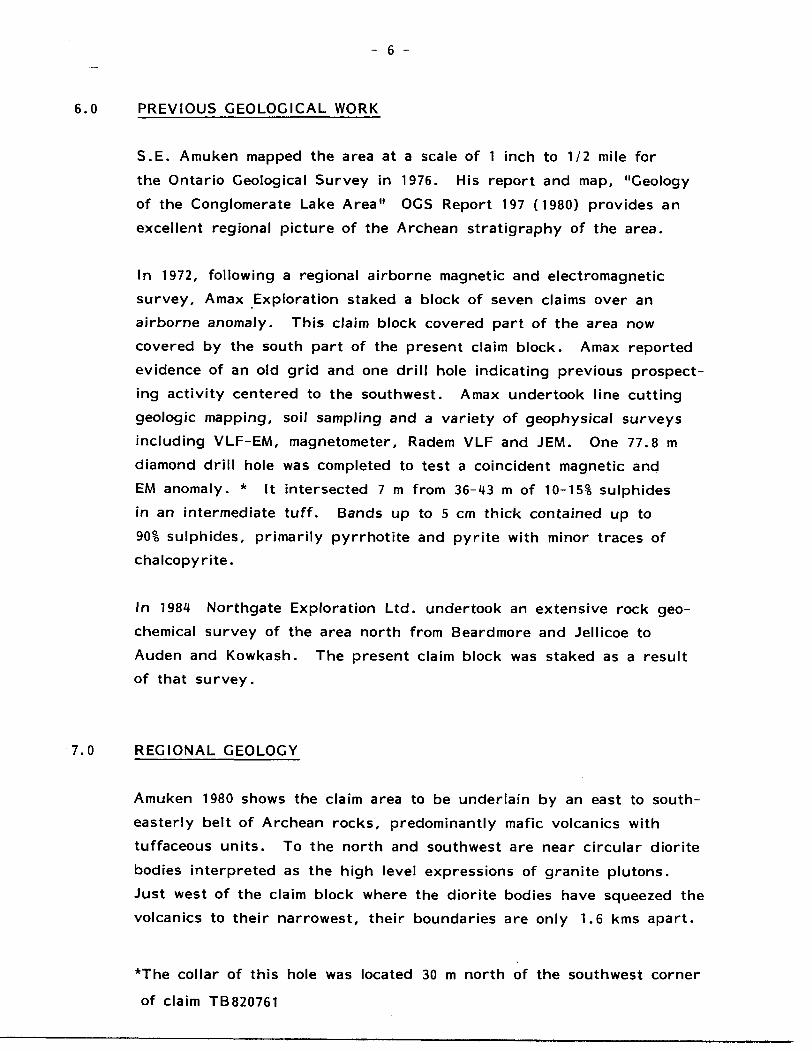
6.0 PREVIOUS GEOLOGICAL WORK
S.E. Amuken mapped the area at a scale of 1 inch to 1/2 mile for
the Ontario Geological Survey in 1976. His report and map, "Geology
of the Conglomerate Lake Area" OGS Report 197 (1980) provides an
excellent regional picture of the Archean stratigraphy of the area.
In 1972, following a regional airborne magnetic and electromagnetic
survey, Amax Exploration staked a block of seven claims over an
airborne anomaly. This claim block covered part of the area now
covered by the south part of the present claim block. Amax reported
evidence of an old grid and one drill hole indicating previous prospect
ing activity centered to the southwest. Amax undertook line cutting
geologic mapping, soil sampling and a variety of geophysical surveys
including VLF-EM, magnetometer, Radem VLF and JEM. One 77.8 m
diamond drill hole was completed to test a coincident magnetic and
EM anomaly. * It intersected 7 m from 36-43 m of 10-151 sulphides
in an intermediate tuff. Bands up to 5 cm thick contained up to
901 sulphides, primarily pyrrhotite and pyrite with minor traces of
chalcopyrite.
In 1984 Northgate Exploration Ltd. undertook an extensive rock geo
chemical survey of the area north from Beardmore and Jellicoe to
Auden and Kowkash. The present claim block was staked as a result of that survey.
7.0 REGIONAL GEOLOGY
Amuken 1980 shows the claim area to be underlain by an east to south
easterly belt of Archean rocks, predominantly mafic volcanics with
tuffaceous units. To the north and southwest are near circular diorite
bodies interpreted as the high level expressions of granite plutons.
Just west of the claim block where the diorite bodies have squeezed the
volcanics to their narrowest, their boundaries are only 1.6 kms apart.
*The collar of this hole was located 30 m north of the southwest corner
of claim TB820761

- 8 -
7.0 REGIONAL GEOLOGY - (Cont'd.)
A variety of later aplite, pegmatite, felsite, granitic and mafic dykes
cut the area. Most are narrow and the commonest trends are north
and northeast.
8.0 GEOPHYSICAL SURVEYS
8.1 GENERAL
During the period August 9-15, 1985 ground magnetometer and VLF-EM
surveys were completed on all the cut lines. The results of these
surveys are shown on the two attached plans in the back pocket of this
report. The magnetometer used was an EG&G Geometrics, Unimag II,
Model G846, portable proton precession magnetometer measuring the total
magnetic field intensity. The VLF-EM instrument used was a Geonics
EM 16 unit which measures the vertical components of secondary fields
radiating from conductive bodies in the ground, which fields are the
result of primary fields transmitted by a worldwide network of VLF
transmitting stations established for communication with submarines.
In this survey the EM 16 was equipped to receive the 24.0 KHz frequency
signal of Cutler, Maine. In all other respects the magnetometer and
EM 16 units were operated in accordance with their standard operating
procedures as described in their manuals.
8.2 MAGNETIC SURVEY
Within the property area a range in magnetic intensity of 2,380 gammas
is recorded ranging from a low of 58,358 to a high of 60,738 gammas.
Over most of the claims there is a rather monotonous background of
59,800 plus or minus 100 gammas. This is banded in an east-southeasterly
direction. The magnetic intensity is generally lower in the east-southeast
and west-northwest with a broad belt 600-800 m wide in the centre of
the property where the values rarely drop below 59,750 gammas. Punct
uating this uniform background are two systems of linear highs and several
very localized highs and lows.

- 9 -
8.0 GEOPHYSICAL SURVEYS
8.2 MAGNETIC SURVEY - (Cont'd.)
The linear high system labelled "C" comprises two sections and is
paralleled by a moderate VLF-EM conductor for almost all its length.
The two sections have a gap of about 100 m associated with a magnetic
depression which extends from the north side of the western section
of C to the south side of the eastern section of C.
The second linear high system comprises several segments labelled
E, F, G and H. These correspond in part with weak to moderate
VLF-EM conductors, the latter being less extensive than the magnetic linears.
Spot highs labelled J and N at the west end of the claims have
coincident weak VLF-EM conductors while the lesser spot high on Line
U W just north of the baseline and the two spot lows on Line 11 W,
north and south of the baseline do not have any corresponding VLF-EM
response.
8.3 MAGNETIC SURVEY INTERPRETATION
With minor disruptions the magnetic expression is of a generally east-
southeast striking layered sequence. Most of the area as indicated by
the geological survey is underlain by intermediate to mafic metavolcanics,
mostly flows or flow breccias with minor tuffaceous interbeds. This
sequence corresponds with the monotonous background magnetic pattern.
The linear magnetic highs, which are conformable to the general strike
of the layered rocks, indicate the presence of narrow almost vertically
dipping units, probably tuffs or cherts with a higher magnetic content
which in places is likely to be sulphides where the VLF-EM confirms
conductors.
Anomaly C appears to be disrupted by a southeast trending low
feature. This feature is likely a dyke or small intrusive body which
has intruded along a fault which caused the slight offset of the two
sections of C and the swing in strike of C approaching it.

- 10 -
8.0 GEOPHYSICAL SURVEYS
8.3 MAGNETIC SURVEY INTERPRETATION - (Cont'd.)
Anomaly E, F, C, H, is probably the result of similar lithology
as C but is offset by two faults, without associated dyking. Folding
or drag rotation of this magnetic unit is also indicated approaching
the fault and there is also an apparent bifurcation of the unit west
wards. Both anomalies C and E, F, C, H can be traced further
than marked on the plan but with much lower relative magnetic
intensity suggesting a significant change in their mineralogy.
North of anomaly E on Lines 00, 1 W and 2 W and possibly on Line 3 E
are indications of another similar linear high but of a lower, more
diffuse character. Overburden depth in this area is likely to be
considerably thicker than over E, which in turn is deeper than C.
Point high J is likely a continuation of the unit from C while point
high N may represent part of the same highly variable horizon as
extends through the point high on Line 4 W, O +2S m N.
The geological mapping shows an intrusive diorite body extending
northward from the north edge of the claims. The diorite is character
ized by a monotonous low magnetic expression similar to the lows.
There is a suggestion that the contact does not trend east-west but
east-southeasterly with several northeasterly offsets either due to
faulting or favourable fracture systems during intrusion.
Interpreted fault zones O and P define a widening wedge southwards
which corresponds to the area of slightly higher background.
8.4 ELECTROMAGNETIC SURVEY
The EM 16 survey revealed one strong conductor A, one moderate
conductor B and several weak conductors C to L. All the conductors
with the exception of E, F, l and L trend east-southeast paralleling
the general geological strike trend. It should be noted that this strike
trend is well oriented with respect to the Cutler, Maine transmitter location.

- 11 -
8.0 GEOPHYSICAL SURVEYS
8.U ELECTROMAGNETIC SURVEY - (Cont'd.)
Conductor A trends ESE for 500 m and is open-ended to the ESE at
the property boundary while at its WNW end it appears to be
terminated at a possible cross conductor L. It is indicative of a near
vertical to steeply south dipping zone probably of sulphides or
graphite with considerable depth. Overburden is shallow.
Conductor B also trends ESE and is open-ended to the WNW at the
property boundary. It has a total length of 800 m. Although displaying
a strong in-phase profile it is not supported by the quadrature, unlike
Anomaly A. This conductor probably is the result of a near vertical
fault or shear zone.
Weak conductors C, D, E, F and C are all indicative of conductive rock
units but probably with low sulphide or graphite contents. Weak
conductors H, l. J, K and L are interpreted as probably shear or fault
zones. Overburden depth over E and the north end of L is substantial.
8.5 ELECTROMAGNETIC CONDUCTOR INTERPRETATION
Conductor A has a strong likelihood of a massive sulphide source.
The lack of magnetic correlation indicates an absence of magnetite or
pyrrhotite. The zone conforms to the regional stratigraphy and is on
strike from a zone of pyrite and pyrrhotite drilled by Amax in 1972
(see accompanying geological report) which gave a high magnetic response
and an EM anomaly.
Conductor B does not have any magnetic support and follows the axis
of a long narrow swamp either side of which is a greater abundance of
outcrops than anywhere else on the property. It trends ESE parallel
to the geologic strike and is likely indicative of an incompetent sheared
tuffaceous unit, possibly with some graphite or sulphides present.

- 12 -
b. J GEOPHYSICAL SURVEYS
8.5 ELECTROMAGNETIC CONDUCTOR INTERPRETATION - (Cont.d)
Conductor C corresponds with a very pronounced linear magnetic
high over its whole length. It is likely a sheet-like zone of weakly
conductive character but some magnetic affinity such as disseminated
pyrrhotite in a tuffaceous unit. Conductor D is similar to C and is
probably the continuation of it beyond a fault disruption (magnetic
fault expression O). The strength of the magnetic anomaly with D
is much less than for C.
Weak conductors E, F and G all correlate with a linear magnetic high
system but are much less extensive than it suggesting that the unit
only locally contains sufficient sulphides to induce a conductive effect.
Weak conductors H, l and J, which do not have magnetic correlations,
may represent intermittent similar sources as E, F and G but are more
characteristic of shear zones in which respect it should be noted they
follow a pair of trends ESE and E sympathetic to and paralleling the
diorite intrusive contact. All are short (of the order of 100-200 m)
and H could be as validly interpreted trending E as ESE, in which case it would suggest an en echelon series of shears.
Conductor K only has a strike extent of 150-200 m and may be largely
the result of conductive overburden although some weakly conductive
bedrock shear component is suspected as well. It has no magnetic
expression.
Conductor L is a very weak expression of a structure, probably a
fault, for which there is some magnetic confirmation in the form of offsets.
- 13 -
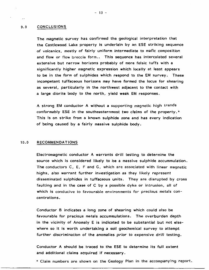
9.0 CONCLUSIONS
The magnetic survey has confirmed the geological interpretation that
the Castlewood Lake property is underlain by an ESE striking sequence
of volcanics, mostly of fairly uniform intermediate to mafic composition
and flow or flow breccia form.. This sequence has intercalated several
extensive but narrow horizons probably of more felsic tuffs with a
significantly higher magnetic expression which locally at least appears
to be in the form of sulphides which respond to the EM survey. These
incompetent tuffaceous horizons may have formed the locus for shearing
as several, particularly in the northwest adjacent to the contact with
a large diorite body to the north, yield weak EM responses.
A strong EM conductor A without a supporting magnetic high trends
conformably ESE in the southeasternmost two claims of the property.*
This is on strike from a known sulphide zone and has every indication
of being caused by a fairly massive sulphide body.
10.0 RECOMMENDATIONS
Electromagnetic conductor A warrants drill testing to determine the
source which is considered likely to be a massive sulphide accummulation.
The conductors C, E, F and C, which are associated with linear magnetic
highs, also warrant further investigation as they likely represent
disseminated sulphides in tuffaceous units. They are disrupted by cross
faulting and in the case of C by a possible dyke or intrusion, all of
which is conducive to favourable environments for precious metals con
centrations.
Conductor B indicates a long zone of shearing which could also be
favourable for precious metals accummulations. The overburden depth
in the vicinity of Anomaly E is indicated to be substantial but not else
where so it is worth undertaking a soil geochemical survey to attempt
further discrimination of the anomalies prior to expensive drill testing.
Conductor A should be traced to the ESE to determine its full extent
and additional claims acquired if necessary.
* Claim numbers are shown on the Geology Plan in the accompanying report.

M.O REFERENCES
Amukun, S.E.1980 : Geology of the Conglomerate Lake Area,
District of Thunder Bay; Ontario Geological
Survey, Report 197, 100 p.
Atkins, T. and Harper, G.
1986 : Line Cutting and Geological Survey of the
Castlewood Lake Claim Block, Thunder Bay
Mining Division, Ontario, NTS 42-E-13;
Northgate Exploration Ltd., unpublished
assessment report.
Thurston, P.C.
1976 : Geology of the North Onaman Area, District
of Thunder Bay; Ontario Division of Mines,
OFR 5197, 118 p.

- 15 -
12'" CERTIFICATION OF CREDENTIALS
l Thomas Atkins certify that:
1) l graduated from McMaster University in 1983 obtaining a
B.Se. degree in Geology.
2) J was employed for two summers prior to my graduation as a
Geological Assistant; working in Ontario and Alberta.
3) l completed an independent study for a B.Se. Thesis.
4) l have been employed by Northgate Exploration Limited as an
Exploration Geologist since graduating ; working in Ontario
and British Columbia.
Thomas Atkins, B.Se.

- 16 -
CERTIFICATION OF CREDENTIALS
l, Gerald Harper, of 26 Orchard Crescent, Toronto, Ontario, declare that:
a) Since 1980 l have been employed as Chief Geologist for Northgate
Exploration Limited of Suite 2701, l First Canadian Place, Toronto,
Ontario.
b) l am a registered member, in good standing, of the Association of
Professional Engineers of the Province of Ontario.
c) l am a 1965, B.Se. Honours graduate of the University of Rhodesia,
having majored in Geology and Chemistry.
d) l was awarded the Ph.D. degree of the University of London,
England, in 1970, for research in the field of geology.
e) l have practiced exploration geology for a period in excess of 20
years, the last 15 being in various Provinces of Canada including,
and in particular, Ontario, Newfoundland and British Columbia.
f) The work undertaken in this report was under my supervision and
l have direct personal knowledge of the performance and abilities
of the author.
Gerald Harper Chief Geologist

4aei3NEoa3i 2.9149 CASTLEWOOD LAKE
Mining Lands Section
Control Sheet
300
File No ^? J/ 5^ 7
TYPE OF SURVEY
MINING LANDS COMMENTS:
GEOPHYSICAL
GEOLOGICAL
GEOCHEMICAL
EXPENDITURE
Signature of Assessor
)ate

Ministry ofNaturalResources
Ontario —
Report of Work(Geophysical, Geological, Geochemical and Expenditures)
- ^---nstruotions: — or print.If ntJTflber of mining claims traversed exceeds space on this form, attach a list.
Note: — Only days credits calculated in the "Expenditures" section may be entered in the "Expend. Days Cr." columns.
\^^Jif M J JffJflT^i/ l lie aiming ri*.l - 1AJ C
Type of Survey(s)
Claim Holder's)
NORTHGATE EXPLORATION LIMITEDW.s BOX 143, 1 FIRST CANADIAN PLACE, TORONTO, ONTARIO
Survey Company Date of S
NORTHGATE EXPLORATION LTD. PJy 1 K
vi.. — uo not ust snaaea areas oeiow.Township or Area
CASTLEWOOD LAKE AREA G'%^Prospector's Licence No.
T835
M5X 1C7
urvey (from St to)
Uo D j l ~JL U i Uo i oJjTOT YT. 1 Day 1 Aflo. 1 ir.
Total Miles of line Cut
22.3 kmName and Address of Author (of Geo-Technical report)
TOM ATKINS c/o NORTHGATE EXPLORATION LTD., - AS ABOVECredits Requested per Each Claim in Columns at rightSpecial Provisions
For first survey:
Enter 40 days. (This includes line cutting)
For each additional survey: using the same grid:
Enter 20 days (for each)
Wan Days
Complete reverse side and enter total (s) here
Geophysical
- Electromagnetic
- Magnetometer
- Radiometric
- Other
Geological
Geochemical
Days perClaim
2020
Geophysicalj Days per ! Claim
- Electromagnetic l
- Magnetometer t
- Radiometric
- Other
Geological
Geochemical
Airborne Credits j
Note: Special provisions l Electromagnetic credits do not apply to Airborne Surveys, j Magnetometer
Radiometric
j Days per i Claim
Expenditures (excludes power stripping)Type of Work Performed
Performed on Claim(s)
Calculation of Expenditure Days Credits
Total ExpendituresTotal
Days Credits
InstructionsTotal Days Credits may be apportioned at the claim holder's choice. Enter number of days credits per claim selected in columns at right.
i m seJe
Apri l 2'86Recorded Hold^6p"rtgwirtJStgTVat
Certification Verifying Report of Wry*
Mining Claims Traversed (List in numerical sequence)
For Office Use OnlyTotal Days Cr.jDate Recorded Recorded
. i
Mining ClaimPrefix
TB
- - -
i ^
-. '.-'i-
~ -.
,i v . i C
1,
\Jf
Number
820752
820753
820754
820755
820756
820757
820758
820759
820760
820761
820762
820763
820764
820765
Expend. Days Cr.
Mining ClaimPrefix
REr t f.*
NlfflW
Number
r - ' - - ~ ~*L u i j i- ~
5.7 M .. r "ia LANlJi) bub l
Expend. Days Cr.
tew—
Total number of mining claims covered by this i ^1 report of work. ^~
irder
l hereby certify that l have a personal and intimate knowledge of the facts set foh m the Report of Work annexed or witnessed same during and/or after its completion and the annexed report isfrue.
ing performed the work
Name and Poital Addreis of Person CertifyingFYDI ORATION t IMITED

May 27, 1986 Report of Work 175
Northgate Exploration UnitedP.O. Box 143l First Canadian PlaceToronto, OntarioM5X 1C7
Dear Sirs:
RE: Mining Claims TB 820752, et al. 1n the Area of Castlewood Lake
We have not received the reports and maps (1n duplicate) for Geophysical (Magnetometer ft Electromagnetic) Surveys on the above-mentioned claims.
As the assessment "Report of Work" was recorded by the Mining Recorder on April 7, 1986 the 60 day period allowed by Section 77 of the Mining Act for the submission of the technical reports and maps to this office will expire on June 6. 1986.
If the material 1s not submitted to this office by June 6, 1986 we will have no alternative but to Instruct the Mining Recorder to delete the work credits from the claim record sheets.
For further Information, please contact Mr. Arthur Barr at (416)965-4888.
Yours sincerely,
J.C. Smith, Supervisor Mining Lands Section
Whitney Block, 6th Floor Queen's Park Toronto, Ontario M7A 1W3
Telephone: (416) 965-4888
AB/roccc: Mining Recorder
Thunder Bay, Ontario175

Ontario
Ministry of Natural Resources
GEOPHYSICAL - GEOLOGICAL - GEOCHEMICAL TECHNICAL DATA STATEMENT
FUe.
TO BE ATTACHED AS AN APPENDIX TO TECHNICAL REPORTFACTS SHOWN HERE NEED NOT BE REPEATED IN REPORT
TECHNICAL REPORT MUST CONTAIN INTERPRETATION, CONCLUSIONS ETC.
Type of Survey(s) GEOPHYSICAL-MAGNETIC AND ELECTROMAGNETIC
Township or A™ CASTLEWOOD LAKE AREA-THUNDER BAY
Claim HnlrfPT(.) NORTHGATE EXPLORATION LIMITED
P.O. Box 143, l First Canadian Place Tor.
Survey nn.np.ny NORTHGATE EXPLORATION LIMITED
Author of Report T. ATKINS AND G. HARPER———————-
Address of Ai.thnr c/o NORTHGATE EXPLORATION LTD.
Covering Dates of——— 01-08-85 - 20-08-85(linecutting to office)
Total Miles of Line r..t 22.3 km (for geological survey)
SPECIAL PROVISIONS CREDITS REQUESTED
ENTER 40 days (includes line cutting) for first survey.ENTER 20 days for each additional survey using same grid.
Geophysical—Electromagnetic.—Magnetometer———Radiometric———Other——————
DAYS per claim
2020
Geological.Geochemical.
AIRBORNE CREDITS (Special provision credits do not apply to airborne surveys)
Magnetometer.
DATE:
-Electromagnetic.(enter days per claim)
SIGNATURE:
. Radiomatric
of Report or Agent
Res. Geol.. . QualificationsPrevious Surveys
File No. Type Date Claim Holder
MINING CLAIMS TRAVERSED List numerically
T.B. 820752(prefix)
820753(number)
820754
820755
820756
820757
820758
820759
820760
820761
820762
820763.
820764
820765
RECEIVEDJ UN '.'"to8b
TOTAL CLAIMS.
837 (5/79)

SELF POTENTIAL
Instrument_____________________________________________ Range.
Survey Method _____________________________________________
Corrections made.
RADIOMETRIC
Instrument ——^
Values measured
Energy windows (levels)^—^—————————^^^————^^^^—.—-.^-^^^^^—-———
Height of instrument_______________________________Background Count.
Size of detector^^—.^—-^^——.^-—-^^^--——.^—^—————.-^^^————.^^^^^-——
Overburden -——-———^^.^^^-————^——.^^-^.—^^——^^^———.——^^^^.————(type, depth — include outcrop map)
OTHERS (SEISMIC, DRILL WELL LOGGING ETC.)
Type of survey.^^-^-—-—^-^——^^———^^—.—
Instrument ̂ —-^—^——.^^^—^^—.^—^———.——
Accuracy—^—-^————^———.^—^——^-————-^—.
Parameters measured.
Additional information (for understanding results).
AIRBORNE SURVEYS
Type of survey(s) ____
Instrument(s) ——————(specify for each type of survey)
Accuracy————-^^—^-———^..—.(specify for each type of survey)
Aircraft used^—^—^^^^^^^——^—.-^^—-^^^———^——.^-^
Sensor altitude.
Navigation and flight path recovery method.
Aircraft altitude _______________________________Line Sparing
Miles flown over total area__________________________Over claims only.

GEOCHEMICAL SURVEY - PROCEDURE RECORD
Numbers of claims from which samples taken.
Total Number of Samples. Type of Sample.
(Nature of Material) Average Sample Weight————————
Method of Collection—————————
Soil Horizon Sampled.
Horizon Development-
Sample Depth—————
Terrain—————————
Drainage Development—————————————
Estimated Range of Overburden Thickness.
ANALYTICAL METHODS Values expressed in: per cent C~ln n
per cent p. p. m. p. p. b.
Cu, Pb,
Others_
Zn, Ni, Co, Ag, Mo, As,-(circle)
Field Analysis (.
E-xtraction Method.
Analytical Method-
Reagents Used———
Field Laboratory Analysis
No. ____________
SAMPLE PREPARATION(Includes drying, screening, crushing, ashing)
Mesh size of fraction used for analysis____
Extraction Method-
Analytical Method .
Reagents Used ——
Commercial Laboratory (.
Name of Laboratory_
Extraction Method——
Analytical Method ——
Reagents Used —^—^—
.tests)
.tests)
-tests)
GeneraL General.

GEOPHYSICAL TECHNICAL DATA
GROUND SURVEYS — If more than one survey, specify data for each type of survey
802 Number of Stations___________________________Number of Readings 802
H WZO
Station interval 25 metres____________________Line spacing IQQ metres
Profile scale____l cm = IO&————^————-——.^——^—^-^—-——-—————————
Contour interval 50 gammas———^-.^——-———————^.^———^^—-^^—-^-^—
Instrument UNIMAC. II PQRTARI E PROTON MAr.NFTOMFTFR MODE! C,
Accuracy — Scale constant 10 ggmmas——^——————^—————.———-^-.——^—.
Diurnal correction method Rago|ino Tje-ln———^-^———-^———————^-^——
Base Station check-in interval (hours)———————^——^————————^——^—-^^—N/ A Base Station location and value '_________________________________
u
o
O
W
Coil configuration VERTICAL AND HORIZONTAL COILSf-4
Coil separation ————-—^^—-^——^^————-——————^—————
Instrument CEONICS EM 16
Accuracy _____~________________________________________________________ Method: C*i Fixed transmitter CD Shoot back CD In line CD Parallel line
24.0 kHz Cutler, Maine U.S.A.-^-———^——^-—————-———^————(specify V.L.F. station)
Parameters measured Tilt Angle of Polarized Ellipse———————^——-^——^——^——^
Instrument
Scale constant.
Corrections made.
Base station value and location .
Elevation accuracy.
Instrument .————.—--———.^-^——^—-^^^—————^——^—^——^^——^—^—-^—-^
Z Method CD Time Domain CD Frequency Domaino ———H Parameters — On time ____________________________ Frequency —————N2
— Delay time
— Off time ____________________________ Range .
Power.
O o*Q WuD Electrode array _Q5 Electrode spacing .
Type of electrode
— Integration time.

2 9149 CASTLEWOOD LAKE 210
magner.c contour depression
't f interpreted from Mag
s of linear magnetic high
SCALE
IOO MET
*- 0~fe ~3J ' " '
T ' 2 5OO
E S25C
NORTHGATE EXPLORATION LIMITEDCASTLEWOOD LAKE PROJ. — No. 731
Cosflewood L^Ke A-ec, District o* Nistgor, ^nunder Say Mng Civ , Cnfano
MAGNETOMETERCONTOUR MAP
T Ath ns Aug '85 l N T S —— 42 E/ 13 | lcm - 25m
z. Or*iz May 96 l
-f/y?

/r-E. M. CONDUCTOR f .
^^mm^Mea^n- QUADRATURE "7 ^"v. Ill- PHASE
"^11 N/ttMMMtfMI H/ea* * t - **
t
, . , T , . r , , , - , [
4O 3lb 2O0* C -20"* -400*POS'TIVE NEGATIVE
-4 \GALE
•43EI3NEa*31 2.9t49 CASTVHWQD LAKE 22O 0 5 1 IV ' ̂ T
M| TRAMSLAJ* ' '
' - -M^—
x0
\\ \ \
.X^^^SS/OyX.
sD- (M^^J^w *i .-t^ .x^O^eoFC^X
1 - 25OO
29C RES
^
\
NORTHGATE EXPLORATION LIMITEDCASTLEWOOD LAKE PROJ. — No. 731
Castlewood Lane Area, DisTic- of Nioigon, Thunder Bay Mng Div , Ontario
VLF-EMPROF 1 LE
Station CUTLER, MAINE Fr*qu*ncy ' 24- KHz
'Ac'- z ~-'-T A'kins Aug '85
0'3*" C, "
Rodel E 0"iz May 86
-) j sNTS —— 4 2 E 7 1 3 lcm z 25m
...,

w t:-\? AWNJFROM DISPOSITION
i UNGhi... 'S C,:' V. "ACE SIGHTS ONt^MMGANDSURrACt , .GriTS
ter W*. OHM O*pc*tto* F**
O)
(3UJ
COUGHLAN L
s
"ll/ l \
\
KABY l
4JE13NE0031 2.9149 CASTLEWOOD LAKE 200
T,
OO'
-5S 1
O N A MA N
It -. C:
1205005
\L- —
,.
C, x' 53'
/
Lu
'Z
ODC UJ .1
ML
L^OTES
TOPOGRAPHY
LAKES. RIVtRS ETC.. FROM FCaEST RESOURCES INVENTOR i' S^CFT So ^:-aS.
ME9ID.AN LINE SURVEYED BY PHILLIPS AN3 BENNER,
O L. S S , 1916. FIELO NOTE BOOK No. 2474.
IHI IN. (.HMATION THAI Al'l'l AHS ON JHI;; MAI HAS R f T N C O M P11 M i f MOM VAHOUS SCniHO'. AMI' ACUJMACY IS Not r.UAMANlFf-f) l H ( .', l WISHINl, 1O SIAKL MIN IN(i C.I AIW5 SIKHII D CON •-III.l WU H fHf MININC. f(! f;OH()[ l! MINISTMY ( )l NOH l H f (IN DI VM Of 1 Ml N! AtJliMINCS F OH AD [JlTlONAt INfOMMAllON ON THf STATUS O( IHf l ANOr, SMOVVN Mf" HI ON
DISPOSmON Of CROWN LANU
TYPE Of DOCUMENTPATENT.SURFACE 8. MINING RIGHTS.
.SURFACE RIGHTS ONLY, ..." .MINING RIGHTS ONLY ___.
LEASE. SURFACE ft MINING RIGHTS -." .SURFACE RIGHTS ONLY.. . ." . MINING RIGK rS ONLY-.. ..
LICENCcOF OCCUPA ION ,___ ,.. ORDER-IN-COUNCIL -. ...____ RESERVATION ___. M ._______ .. CANCELED __ ______ _. SAND St GRAVEL . __ .^ " . _. .1
SYMBOL
e e
aT
___- d)NOTE: MINING KIG* Tt IN P V^CEL. f ATiNT w
19.J. VMTtU IN OW.GIHAL *-AT(MTrt BY JM UBLIC LAND* ACT. W**, t. TO. CHAP 3-0. S*C. ' *. SUSSc- t.
LEGEND-
P\VFO ROAD
GRAVFL i'C^O
CThTR RCADS
TRAIL O^ ' ; .iT
AD c. KIGHT or W*Y! RAP'
ILANDU.SI
. -' - T '-. D
v;' 1 c i-, 'i; r '-v'^
SCALE: 1 INCH * 40 CHAINS
FEET 4000 eooo 8OOO
AREA CASTLEWOOD LAKE
M. N. R. ADMINISTRATIVE DISTRICT
NIPIG 8
soenv
DIVISIOI THUNDER BAY
CAND TITLES/ REGISTRY DIVISION
' 'THUNDER BAY
Ci*i! * JUIY, I960MNflt'o*f
floc