
GPS World - January 2013
76
description
GPS World
Transcript of GPS World - January 2013


A T R I M B L E C O M P A N Y

www.gpsworld.com January 2013 | GPS World 3
January 2013Vol. 24, Number 1gpsworld.com
» coVer storY
Spectrum Interference Standards
Out in Front 6Let the Chips FallBy Alan Cameron
exPert advice 8High-Level Perspective on PNT FrontiersBy James D. Litton
the SyStem 18Galileo IoV-3 broadcasts e1, e5, e6 signals; russian sbAs luch-5b in orbital slot; eGNos and Galileo in emergency call, road tolling; compass IcD rumored
the buSineSS 29locata lands Air Force contract; raytheon uK GPs Anti-Jam; Navman Wireless Professional Fleet tracking; u-blox medical Alert system; leica Viva Gs14; events; there’s an App for GPS World; and more
An Evolving SAASM Receiver Story 74Excerpt from Profession OEM Newsletter by Tony Murfin
OPiniOnS & dePartmentS
2013 Receiver Survey 35SPecial 24-PaGe inSert
the only authoritative industry resource for GPs chipset, module, and receiver manufacturing furnishes detailed design and performance specifications for more than 500 receivers from 55 companies.
INNOVATIONGetting at the Truth 67A Civilian GPS Position Authentication SystemIt’s not difficult to generate false position reports and mislead a monitoring center into believing a receiver is located elsewhere — unless an authentication procedure is used. A clever system uses the concept of supplicant and authenticator to assess the truthfulness of position reports.By Zhefeng Li and Demoz Gebre-Egziabher
Seeking a Win-Win Rebound from Lose-Losebased upon lessons learned from the lightsquared situation, the author identifies important considerations for GPs spectrum interference standards, recommended by the PNt eXcom for future commercial proposals in bands adjacent to the rNss band to avoid interference to GNss.By Christopher J. Hegarty Bow highrise in Calgary; photos courtesy Rocky Annett, MMM Group Ltd.
Sponsored by | receiver Survey 2013
www.gpsworld.com
January 2013 | GPS World 39
Cold start 3
Warm start 4Reacquisition 5
No. of portsPort type
Baud rate
Operating temperature (degrees Celsius)Power source Power consumption (Watts) Antenna type 6
Description or Comments
<45s<15s
<1s
4
2 RS-232, 1 Bluetooth, 1 TNC1,200-115,200
-20 to +65INT/EXT (9-18 V DC) 7 W
INT/EXT
Dual Frequency Geodetic and RTK GNSS receiver
<45s<15s
<1s
4
2 RS-232, 1 Bluetooth, 1 TNC1,200-115,200
-20 to +65INT/EXT (9-18 V DC) 7 W
INT/EXT
Triple Frequency Geodetic and RTK GNSS receiver
<45s<15s
<1s
4
2 RS-232, 1 Bluetooth, 1 TNC1,200-115,200
-20 to +65INT/EXT (9-18 V DC) 7 W
INT/EXT
Dual Frequency Geodetic and RTK GNSS & TERRASTAR
L-Band receiver
<45s<15s
<1s
8
3 RS-232, 1 Bluetooth, 1 USB, 1 Ethernet, 2 TNC
1,200-115,200-20 to +65
EXT (9-30 V DC) 11 W
EXTERNAL (1 or 2)Dual or Triple Frequency Geodetic and RTK, GNSS
Heading, & TERRASTAR L-band receiver
45s35s
3s
3
RS-232, RS-232, USB 2.01 RS232 up to 921.6 kbits/sec (RxD, TxD, CTS and RTS signals)
–40 to +85external
< 0.8W in GPS L1; < 0.95W in GPS L1/L2 or GPS+GLONASS L1
Ext. active patch/antenna.; 2 antenna connectors Compact Dual-Frequency RTK OEM Board.; 2 antenna
connectors for handheld integration.; BLADE Technology
inside.
45s35s
3s
4
RS-232, LV-TTL, LV-TTL, USB 2.0RS-232 up 921.6 kbits/sec; LV-TTL up to 5 Mbits/sec; USB 2.0 up to 12 Mbps
-40° to +185°Fexternal
1.9W (GPS only),; 2.4W (GPS+GLONASS)Ext. active antenna (L1, L2) GPS/GLONASS
GPS+GLONASS+SBAS Dual-Frequency OEM Board.;
Z-BLADE Technology inside.
nrnr
<3s
2
RS-230
300–115,200–30 to +70
external3
Patch, active (ER)
For aviation; designed to FAA/RTCA speci¿cations
45s35s
3s
6
3x RS-232, USB 2.0, Bluetooth, Ethernet RS-232 up 921.6 kbits/sec; USB 2.0 up to 12 Mbps; -22° to +149°F
external5W with one GNSS antenna Ext. active antenna (L1, L2) GPS/
GLONASSGPS+GLONASS+SBAS Dual-board RTK+Heading System.;
Z-BLADE Technology inside.
90s35s
3s
2
RS-232
300–115,200–20 to +55
external6
Patch with ground plane (ER)Precise heading, pitch, roll, and 3D position
90s35s
3s
3
RS-232
300–115,200–30 to +70
external1.2
Microstrip GPS/beaconUses SBAS signals for sub-meter differential positioning
90s35s
3s
3
RS-232
300–115,200–30 to +60
external1.3
Microstrip GPS/beaconSub-meter GPS+Beacon+SBAS receiver
45s35s
3s
3 - 4 2-3 RS-232, USB 2.0,
-22° to +140°Fexternal
2.4 W - 6.5 WGNSS, GLONASS, Galileo, SBAS GNSS-centric engine. GLONASS-only capable. Z-BLADE
Technology inside.
<8 min<50 s
2-5 s
4
RS-422
9600–38,400–25 to +60
ext/int5.5
patch (E)
For LEO satellites
<2min20 s
2–5 s
1,1RS-422, RS-232
9,600–38,400–40 to +85
ext3.75
patch (E)
Smart munitions
<2min20 s
2–5 s
1,1RS-422, RS-232
9,600–38,400–40 to +85
ext3.75
patch (E)
Inertial system integration
<2min20 s
<1s
1, 1RS-232, RS-422
300–19,200–40 to +71
ext/int6
patch (E)
Satellite launchers, missiles
<2min20 s
<5 s
1, 1RS-232, RS-422
300–38,400–40 to +71
ext/int4.5
patch (E)
A/C PODS
<2min5s
<1s
1,1RS-422, RS-232
9,600–115,200–40 to +71
ext14
4X patch (E)
Artilery GPS Àight computer
<2min20s
2–5 s
1,1RS-422, RS-232
115200
–40 to +85ext
4.5
patch (E)
10-MHz in, 2x1PPs out
<2min13 s
3 s
2
TTL
9,600–115,200–40 to +85
ext1
nr
GPS for artilery
<2min6 s
3 s
2
TTL
9,600–115,200–40 to +85
ext/int3
nr
GPS for artilery
<2min5s
<1s
1,1RS-422, RS-232
9,600–115,200–40 to +71
ext14
4X patch (E)
A/J GNSS for high dynamics
2ms2ms
2ms
na
na
na
na
nana
na
SW based GPS receiver
2ms2ms
2ms
2
Serial/Parallel
na
TBD
3.3TBD
na
RFIC module
30s30s
1s
3
I2C, SPI, UART
Up to 1/32 of reference clock –30 to +851.5-3.6 V
13mW
na
Single-chip, single-die baseband and RF tuner
30s30s
1s
3
UART, SDIO, SPI,I2C,PCM, I2SUART: 4M
-30 to +851.2V - 5.5V
10mW
na
Single chip, single die, GPS + GLONASS + Bluetooth +
FM (RX/TX)
30s30s
1s
2
UART, I2C
UART: 4M
-30 to +851.5-3.6 V
13mW
na
Single chip, single die, GPS + GLONASS baseband
and RF tuner
30s30s
1s
96
GPIO, HS UART (x4), SPI, I2C, SDIO/MMC (x3), PCM, I2S UART: 4M
-40 to +85 CCore: 1.2V, I/O: 3.3V, Audio 3V
300mW @ 700MHzna
Highly intergrated ARM11 Apps Processor + VFPU + GPS
Baseband + RF + LNA with support of DDR2
30s30s
1s
2
UART, I2C
UART: 4M
-30 to +851.5-3.6 V
13mW
na
Single chip, single die, GPS + GLONASS baseband
and RF tuner
33s33s
<1s
1
SPI
2 Mbps
–40 to +85Single 1.8v supply 20mW average
na
Single die GPS/AGPS baseband and RF front end
33s33s
<1s
1
SPI
2 Mbps
–40 to +85Single 1.8v supply 20mW average
na
GPS/AGPS Module
33s33s
<1s
1
SPI
2 Mbps
–40 to +85Single 1.8v supply 20mW average
na
Two dies solution. GPS/AGPS baseband and RF front end
+ electronic compass
33s33s
<1s
1
APB
2 Mbps
na
nana
na
GPS/AGPS baseband IP for integration with host-processor
system
33s33s
<1s
1
APB
8 Mbps
na
nana
na
GPS/AGPS baseband IP for integration with host-processor
system
nana
na
1
Serial
12-26 Msps–40 to +85
Single 1.8v supply 30mW maxna
Single die GPS RF front-end
<45s<20s
<1s
2
RS-232
19200-115200“-20 to +70°C”
int LiPo/ext 9-30V 5W
active, external
<35s<34s
<1s
2
UART, SPI, I2C
user selectable-40 to +85
Ext0.008
E
Single die tracker
<35s<34s
<1s
2
UART, SPI, I2C
user selectable-40 to +85
Ext0.008
E
Single die engine
<35s<34s
<1s
na
na
user selectable-40 to +85
Ext~ 0.7 to 0.9
E
SOC: Apps Processor + GPU + GPS
<35s<34s
<1s
na
na
user selectable-40 to +85
Ext~ 0.7 to 0.9
E
SOC: Apps Processor + GPU + GPS
<35s<34s
<1s
na
na
user selectable-40 to +85
Ext~ 0.7 to 1.5
E
SOC: Apps Processor + GPU + video + GPS
<35s<34s
<1s
na
na
user selectable-40 to +85
Ext~ 0.7 to 1.5
E
SOC: Apps Processor + GPU + video + GPS
<35s<34s
<1s
na
na
user selectable -20 to +70
Ext~ 0.55 to 0.9
E
SOC: Apps Processor + GPS
<35s<34s
<1s
na
na
user selectable -20 to +70
Ext~ 0.55 to 0.9
E
SOC: Apps Processor + GPS
<35s<34s
<1s
na
na
user selectable-40 to +85
Ext~ 0.55 to 1.5
E
SOC: Apps Processor + GPU + GPS
<33s<32s
<1s
2
UART, SPI, I2C
user selectable-40 to +85
Ext0.008
E
Single die GNSS engine
<33s<32s
<1s
2
UART, SPI, I2C
user selectable-40 to +85
Ext0.008
E
single die tracker
<40s36s
<1s
1, 1, 1, 1Serial, A/D, USB, Bluetooth
1,200–115,200 bps–30 to +70
int., ext., LiIonP. 2.2
L1/L2 (E)
GPS L1/L2 carrierphase and data collection. WR
<40s36s
<1s
2, 1, 1, 1Serial, A/D, USB, Bluetooth
1,200–115,200 bps–30 to +70
int., ext, ., LiIonP. 3.2
L1/L2 GNSS (E)
RTK,VRS, Precision post-procecssing, Precision GIS, GSM
modem opt. WR
<40s36s
<1s
1,1PC Card (PCMCIA), USB
1,200–115,200 bps-40 to +85
ext.1.5
L1/L2 GNSS (E)
RTK,VRS, Precision post-procecssing, Precision GIS, GSM
modem opt. WR
<40s36s
<1s
1,1USB, Bluetooth option
1,200–115,200 bps-40 to +85
int., ext, ., LiIonP. 1.5 to 2
L1/L2 GNSS InternalRTK,VRS, Precision post-procecssing, Precision GIS, GSM
modem opt. WR. Fully wireless operation capable.
<40s<36s
<1s
2
Serial
1,200–115,200 bps–40 to +85
ext.1.5
L1/L2 GNSS (E)
Based on easy-to-upgrade/modify FPGA design
<40s<36 s
<1s
2
Serial
1,200–115,200 bps–40 to +85
ext.1.5
L1/L2 GNSS (E)
as above
<<34s<33s
<1s
1
1 BT
57600
–20 to +50internal battery
Active, 27 db
5 min2 min
< 1 min
2
1 Ethernet, 1 RS-232
10/100 Base-T, 192000 to +50
External< 10W
L1 (ER)
GPS Time & Frequency
5 min2 min
< 1 min
2
1 Ethernet, 1 RS-232
10/100 Base-T, 192000 to +50
External< 7W
L1 (ER)
GPS Time & Frequency
5 min2 min
< 1 min
2
1 Ethernet, 1 RS-232
10/100 Base-T, 192000 to +50
External< 7W
L1 (ER)
NTP and PTP/IEEE-1588
5 min2 min
< 1 min
2
1 Ethernet, 1 RS-232
10/100 Base-T, 192000 to +50
External< 7W
L1 (ER)
NTP and PTP/IEEE-1588
ext
external, active
<40s<38s
<3s
4
RS-232, CMOS
-40 to +85ext
<1W
external, active
SAASM
p
Baud rate
aturegrees Celsius)Power consump(Watts)
<45s<15s
<1s
4
2 RS-232, 1 Bluetooth, 1 TNC1,200-115,200
-20 to +65INT/EXT (9-18V DC) 7 W
<45s<15s
<1s
4
2 RS-232, 1 Bluetooth, 1 TNC1,200-115,200
-20 to +65INT/EXT (9-18V DC) 7 W
<45s<15s
<1s
4
2 RS-232 1 Bluetooth 1 TNC1 200-115 200
-20 to +65INT/EXT (9-18 7 W
9-30 V DC) 11 W
al< 0.8W in GPS L1; <0.95W in GPS L1/L2 orGPS+GLONASS L1
al1.9W (GPS only),; 2.4W(GPS+GLONASS)
E
G
al3
Patal
5W with one GNSSantenna Ext. aGLON
al6
Patch w
al1.2
Microstr
al1.3
Microstrial2.4 W - 6.5 W
GNSS, G
5.5
patch (E)3.75
patch (E)3.75
patch (E)6
patch (E)4.5
patch (E)14
4X patch (E4.5
patch (E)1
nr3
nr14
4X patch (E)na
naTBD
na
6 V13mW
na5.5V10mW
na6 V13mW
na1.2V, I/O:Audio 3V
300mW @ 700MHzna6 V
13mW
na1.8v supply 20mW averagena1.8v supply 20mW average
na1.8v supply 20mW averagena
na
nana
na1.8v supply 30mW maxna
o/ext 9-30V 5W
active, ex0.008
E0.008
E~ 0.7 to 0.9E~ 0.7 to 0.9
E~ 0.7 to 1.5E
~ 0.7 to 1.5E
~ 0.55 to 0.9E~ 0.55 to 0.9E~ 0.55 to 1.5E
0.008
E0.008
Ext., LiIonP. 2.2
L1/L2 (E)xt, ., LiIonP. 3.2
L1/L2 GNSS (E
1.5
L1/L2 GNSS (E)xt, ., LiIonP. 1.5 to 2
L1/L2 GNSS Int
1.5
L1/L2 GNSS (E
1.5
L1/L2 GNSSal battery
Active, 27 dbal
< 10W
L1 (ER)al< 7W
L1 (ER)al< 7W
L1 (ER)al< 7W
L1 (ER)external, act<1W
external, acti
Now in its 21st year, the annual GPS World Receiver Survey provides
the longest running, most comprehensive database of GPS and
GNSS equipment available in one place.With information provided by 55 manufacturers on more
than 502 receivers, the survey assembles data on the most
important equipment features. Manufacturers are listed
alphabetically. Footnotes and Abbreviations below supply
additional information to guide you through the survey.
We have made every effort to present an accurate listing
of receiver information, but GPS World cannot be held
responsible for the accuracy of information supplied by the
companies or the performance of any equipment listed. In
some cases, data had to be abbreviated or truncated to fit
the space available. Contact the manufacturers directly with
questions about specific units. To be listed in the 2014 Receiver
Survey, e-mail [email protected].
abbreviations apps: applications
ARINC: Aeronautical Radio, Inc.
standard async: asynchronous
bps: bits per second
CP: carrier phase
CEP: circular error probable
diff: differential
ext.: external / int. = internal
m, min: minutes na or NA: not applicable
nr: no response
opt.: optional par.: parallel prog.: programmable
ppm: parts per million
RMS: root mean square
s: seconds SBAS: Satellite-Based
Augmentation System
typ.: typical
VRS: Virtual reference station
WP: waterproof
WR: water resistant
notes1 User environment and applications: 2 Where three values appear, they
refer to autonomous (code), real-time
differential (code), and post-processed
differential; where four values appear,
they refer to autonomous (code),
real-time differential (code), real-
time kinematic, and post-processed
differential.3 Cold start: ephemeris, almanac, and
initial position and time not known.4 For a warm start, the receiver has
a recent almanac, current time,
and initial position, but no current
ephemeris5 Reacquisition time is based on the
loss of signal for at least one minute.6 E = provision for an external antenna
R = antenna is removable
A = aviation C = recreational D = defense G = survey/GIS H = handheld L = land M = marine
Met = meteorology N = navigation O = other P = other position reporting
R = real-time DGPS ref.
S = space T = timing V = vehicle/vessel tracking
1 = end-user product
2 = board/chipset/module for
OEM apps

ONLINE RESOURCES
Looking for an article? GPSworld.com has moved to a new server, and
is adding new content every day. Our Archive
page (www.gpsworld.com/archives) hosts our
back issues in Digital Edition form.
Digital Editions can be easily downloaded to
your desktop for reading at your leisure. Once the
issue loads in your browser, simply click on the
PDF (down arrow) button on the right-hand side.
GPS World Archives
www.gpsworld.com/archives
October 2012 September 2012 August 2012
June 2012 May 2012 April 2012
July 2012
March 2012
February 2012 January 2012 December 2011 November 2011
October 2011 September 2011 August 2011 July 2011
II GPS World I January 2013
APP FOR iPad®
NOW AVAILABLEI
FREE DOWNLOAD
IT TO DAY I Search GPS World HD on the App StoreSM
Direct link: http://itunes.com/apps/GPSWorldHD
For more information, visit GPSWorld.com
Apple logo and iPad are trademarks of Apple Inc., registered in the countries. App Store is a

4,147,200 COLOR DROPLETS
EPSON SureColor T3000 - 24" | $2,995
EPSON SureColor T5000 - 36" | $3,995
EPSON SureColor T7000 - 44" | $4,995
THE NEW EPSON®
SURECOLOR®
T-SERIES
¥ Extreme plotting accuracy at resolutions up to 2880 x 1440 dpi
¥ Advanced pigment ink technology for durable, photographic-quality plots
¥ Capable of producing a precise, color, D-sized plot in 25 seconds
¥ High-capacity ink cartridges up to 700 mL for low printing cost
¥ Space-saving design with easy access front-loading paper and ink
Speeds are based upon print engine speed only.Total throughput times depend upon factors such as computer, file size, printer resolution, ink coverage, and networking. For the SC-T3000, top speed for a D-sized plot is 28 seconds. Prices are MSRP, before rebates. Please check with an EPSON Professional Imaging Authorized Reseller for actual price as dealer prices may vary. EPSON and SureColor are registered trademarks and EPSON Exceed Your Vision is a registered logomark of Seiko Epson Corporation. Copyright 2012 Epson America, Inc.
PER INCH 1"
1"
Our plotters
deliver brilliant
photographic
output up to
2880 x 1440 dpi.

GPS World | January 2013 www.gpsworld.com6
out in front
editorial
Editor-in-Chief and Publisher Alan Cameron | [email protected] Managing Editor Tracy Cozzens | [email protected] Art Director Charles Park | [email protected]
EDITORIAL OFFICES 1360 East 9th St, Suite 1070 IMG Center Cleveland, OH 44114, USA 847-763-4942 | Fax 847-763-9694 www.gpsworld.com | [email protected]
ContributinG editorS
Innovation Richard Langley | [email protected] Defense PNT Don Jewell | [email protected] LBS Insider Kevin Dennehy | [email protected] Professional OEM Tony Murfin | [email protected] Survey/GIS Eric Gakstatter | [email protected] Aviation Bill Thompson | [email protected] Wireless Pulse Janice Partyka | [email protected]
advertiSinG
Associate Publisher and International Account Manager Chris Litton | [email protected] | 323-229-6165
Marketing Manager Ryan Bockmuller | [email protected] | 216-706-3772
PubliShinG ServiCeS
Manager, Production Services Chris Anderson | [email protected]
Sr. Audience Development Manager Antoinette Sanchez-Perkins | [email protected]
PRODUCTION OFFICE 1360 East 9th St, Suite 1070 IMG Center Cleveland, OH 44114 216-978-9778
CIRCULATION/SUBSCRIBER SERvICES [email protected] | USA: 847-763-4942
north CoaSt Media, llC.
President & CEO Kevin Stoltman | [email protected] | 216-706-3740
vice President of Finance & Operations Steve Galperin | [email protected] | 216-706-3705
vP Graphic Design & Production Pete Seltzer | [email protected] | 216-706-3737
ManuSCriPtS: GPS World welcomes unsolicited articles but cannot be held responsible for their safekeeping or return. Send to: 1360 East 9th St, Suite 1070, IMG Center, Cleveland, OH 44114, USA. Every precaution is taken to ensure accuracy, but publishers cannot accept responsibility for the accuracy of information supplied herein or for any opinion expressed. rePrintS: Reprints of all articles are available (500 minimum). Contact 877-652-5295, Nick Iademarco. Wright’s Media, 2407 Timberloch Place, The Woodlands, TX 77380. SubSCriber ServiCeS: To subscribe, change your address, and all other services, e-mail [email protected] or call 847-763-4942. PerMiSSionS: Contact 877-652-5295, Nick Iademarco. Wright’s Media, 2407 Timberloch Place, The Woodlands, TX 77380. international liCenSinG: Contact e-mail [email protected]. aCCountinG offiCe and offiCe of PubliCation: 1360 East 9th St, Suite 1070, IMG Center, Cleveland, OH 44114, USA.
GPS WORLD does not verify any claims or other information appearing in any of the advertisements contained in the publication and cannot take any responsibility for any losses or other damages incurred by readers in reliance on such content.
www.gpsworld.com
Published monthly
We either continue to totter at
the brink of a global financial
precipice, or we sit crumpled
on the canyon floor far below, peering
skyward, wondering what might have
been, and resolving to pick up what
pieces we can and carry on.
It is impossible to tell as this
magazine goes to press in December
just where we may find ourselves, and
in what shape, come the early days of
January 2013. Those elected parties
with responsibility for the state of our
fiscal affairs, who in the best of all
possible worlds would possess some
sort of vision for the future, continue
to posture, prevaricate, pander, and
generally excuse themselves from
worrying about what may happen to the
rest of us. After all, they will still be in
office and drawing good salaries come
the New Year, come what may.
The GNSS industry has pulled
through the last half-decade of
worldwide recession as well as most,
better than many. There have been
some casualties along the way, and
almost universal belt-tightening.
But we keep moving onward and
upward, blessed with a technology
that continues to find new and profit-
bearing applications, and encouraged
by researchers further out in front of us,
who discover and develop yet newer
possibilities at an astonishing rate.
Now we face new uncertainty. The
domino-paths of the global economy
wend this way and that, curving,
intertwining, doubling back, snaking
everywhere. A toppled piece here can
lead to a cascaded pile-up way over
on the other side of the board, and vice
versa.
It all comes down to end-user ability
to buy, to upgrade, to invest in the
future — as opposed to holding tight
to whatever can be preserved in the
present.
If characterizing GNSS end-users
could be done by naming off surveyors,
farmers, fishermen, and other outdoor
enthusiasts, then determining the
economic outlook for this industry
would be easier to do, though the
picture might not necessarily be any
more optimistic. But the GNSS end-
user community has swelled almost
immeasurably to include the automotive
industry, the telecommunications
industry (in both its infrastructure and
its own end-user equipment), utilities,
airlines and the aircraft industry,
militaries around the world, and even
governments themselves — municipal,
state, and national. Every one of these
entities has a budget and acutely feels
the chills — and in more delayed
fashion, the warmings — of national
and global economies.
Should the United States Congress,
in full possession of all its political
wisdom, drive the country over the
fiscal precipice, reverberations of
the crash in the chasm below will
propagate far and wide — and into the
very marrow of our bones.
We have overcome before. With
science and technology as our co-pilots
(or are they our engines?), we shall
overcome again. We may and should
speak out, attempting to influence the
political process, but we cannot control
its outcomes.
We can do our own jobs, and we
will. Accept change, keep calm, carry
on.
Let the Chips Fall
The GNSS industry has pulled through the last half-decade of worldwide recession as well as most, better than many. Now we face new uncertainty.

When you’re working in remote locations, the last thing
you want to worry about is infrastructure. You need reliable
positioning, here and now.
Septentrio receivers, supported by TERRASTAR™ services,
can now realize reliable global DGNSS positioning with
an accuracy to 10 cm for people, vehicles and other assets
anywhere on land. Positioning that does not require local
base stations, radios or cell coverage.
With a background as one of the early innovators in
precise positioning, TERRASTAR™ is a leader in precise
land navigation, positioning, and guidance solutions.
TERRASTAR™ uses both GPS and Glonass satellites, and
its own worldwide network of reference stations to assure
accuracy, availability and reliability.
Why Septentrio?
Because we are reliable experts.
Because we are ahead.
“Septentrio has implemented TERRASTAR™ Global DGNSS services in its high quality GNSS
receivers, so people now have access to decimeter accuracy even
in the most remote areas, without the need for
ground infrastructure.”Giles Mack,
Business Director TERRASTAR™
Visit us at www.septentrio.com
GPS World | January 2013 www.gpsworld.com8
expert advice
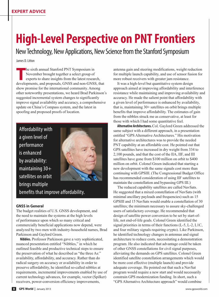
The sixth annual Stanford PNT Symposium in
November brought together a select group of
experts to share insights from the latest research,
developments, and proposals, GNSS and non-GNSS, that
show promise for the international community. Among
other noteworthy presentations, we heard Brad Parkinson’s
suggested incremental system changes to significantly
improve signal availability and accuracy, a comprehensive
update on China’s Compass system, and the latest in
spoofing and proposed proofs of location.
GNSS in General The budget realities of U.S. GNSS development, and
the need to maintain the systems at the high levels
of performance upon which so many critical and
commercially beneficial applications now depend, were
analyzed by two men with industry-household names, Brad
Parkinson and Gaylord Green.
Nibbles. Professor Parkinson gave a very sophisticated,
nuanced presentation entitled “Nibbles,” in which he
outlined feasible and productive technical steps to ensure
the preservation of what he described as “the three As:”
availability, affordability, and accuracy. Rather than do
radical surgery on accuracy or availability in order to
preserve affordability, he identified so-called nibbles at
requirements, incremental improvements enabled by use of
current technology advances, for example, vector (Spilker)
receivers, power-conversion efficiency improvements,
antenna gain and steering modifications, weight reduction
for multiple launch capability, and use of sensor fusion for
more robust receivers with greater jam resistance.
It was a high-level but quantitative system design
approach aimed at improving affordability and interference
resistance while maintaining and improving availability and
accuracy. He made the salient point that affordability with
a given level of performance is enhanced by availability,
that is, maintaining 30+ satellites on orbit brings multiple
benefits that improve affordability. The estimates of gain
from the nibbles struck me as conservative, at least for
those with which I had some quantitative feel.
Alternative Architectures. Col. Gaylord Green addressed the
same subject with a different approach, in a presentation
entitled “GPS Alternative Architectures.” His motivation
for alternative architectures was to provide the needed
PNT capability at an affordable cost. He pointed out that
GPS satellites have increased in dry weight from 334 to
2,100 pounds, and that the cost of the IIA, IIF, and III
satellites have gone from $100 million on orbit to $400
million on orbit. Colonel Green indicated that starting a
new development with the same signals cost more than
continuing with GPSIII. (The Congressional Budget Office
has recommended consideration of using IIF satellites to
maintain the constellation and bypassing GPS III.)
The reduced capability satellites are called NavSats.
He suggested that a mixed constellation of NavSats (with
minimal ancillary payloads and frequencies) such as 15
GPSIII and 15 NavSats would enable a constellation of 30
satellites; the minimum necessary to assure sky-challenged
users of satisfactory coverage. He recommended that
design of satellite power conversion to be set by start-of-
life, not end-of-life goals. Colonel Green identified the
signal priorities in terms of their functions (L-5, L-2, L1C,
and four military signals requiring crypto). Like Parkinson,
he identified technology changes in antennas and signal
architecture to reduce costs, necessitating a demonstration
program. He also indicated that advantage could be taken
of other GNSS constellations for civil signal purposes,
alleviating the demands on GPS satellites. Colonel Green
identified satellite constellation arrangements which would
be more cost effective (multiple launch) and provide
adequate coverage. He pointed out that such a NavSat
program would require a new start and would necessarily
constrain GPS modernization funding. In short, such a
“GPS Alternative Architecture approach” would combine
High-Level Perspective on PNT FrontiersNew Technology, New Applications, New Science from the Stanford SymposiumJames D. Litton
Affordability with a given level of performance is enhanced by availability: maintaining 30+ satellites on orbit brings multiple benefits that improve affordability.
www.trimble.com
GPS World | January 2013 www.gpsworld.com10
expert advice
continuation of GPS III as planned with the addition of
simpler, lighter satellites with reduced diversity of signals
to replace the aging GPS satellites now on orbit beyond
their design life.
Compass. Professor Jingnan Liu of the GNSS Research
Center of Wuhan University gave what most observers
thought was the first comprehensive and data-intensive
description of Precise Positioning results with the
COMPASS (Beidou) system. He showed that the Beidou
regional system, from which he presented copious data, can
currently provide standard positioning service with <10M
horizontal and <20M vertical accuracies at 95% confidence
level. He also showed that results with Beidou plus GPS
are 10-20% better than GPS alone. He provided results
for surveying, for ground-based augmentation, for RTK,
PPP, clock stability, orbital statistics, wide area differential
and many other metrics of PNT. Professor Parkinson
noted, in appreciating the presentation, that it was the first
detailed release of so much technical data on COMPASS
performance. The results noted above were obtained with
4GEO+5 IGSO+2MEO satellites. The constellation is
expected to grow to 5GEO+5IGSO+4MEOs by the end
of 2012 and to 5GEOs+3IGSOs+27 MEOs by 2020 for
a global service. The amount of data and the diversity
(application and instrumentation) of the data were truly
impressive.
GPS Modernization. Dr. Keoki Jackson of Lockheed Martin
presented a comprehensive review of GPS Modernization
with charts which described the evolution of GPS from
Block I to Block III. He depicted the program as on
schedule for delivery of the first GPS III vehicle in May,
2014, with a 2015 launch. Most of this material was the
same as reported from the AFCEA GC-12 program in GPS
World earlier this year. A matrix comparing the attributes of
GPS III with GPSII and beneficial outcomes from “Back-
to-Basics Investments” were key takeaways.
Ground Control. Ray Kolibaba of Raytheon presented
a detailed overview of the OCX program, the next
generation Operational Control System. This presentation
also emphasized improvements in program management,
simplification of development practices, extensive use of
commercial development methods and predicted on-time
delivery with all of the attributes needed for both GPS III
and the existing constellation.
Military User Equipment. Col Bernie Gruber, Director of
the GPS Directorate, gave an update on current activities
with emphasis on progress in Military User Equipment
(MGUE) development. This material was somewhat further
advanced in schedule than the equivalent May 2012 time
frame in which the same subject was presented in much
detail at the AFCEA GC-12 meeting at the Directorate.
The currently ‘hot’ topics of jamming and spoofing threats,
countermeasures and affordability were prominent in the
presentation. Some of the key achievements for 2012 listed
were the release of BAAs (Broad Agency Announcements)
for NavSat studies and the completion of a Congressional
Report on ‘Cost Effective GPS). Launch of GPS IIF-3 and
delivery of GPS IIF-4, 5,6 & 7 were also noted. Security
Certification for MUE cards was a very noteworthy
achievement, which will make future MGUE development
and utilization much easier for the challenging jamming
and spoofing environment which is expected. The themes
of affordability and jamming and spoofing threats were
dominant in this review, as well.
General PNTNorvald Kjerstad is a professor of Nautical Science at
Aalesund University College and a long-time professional
navigator in academic, geophysical, and shipping
communities. His paper vividly depicted the risks brought
about by climate change, by increased commercial interest
in shipping and mineral resource exploration in the Arctic
region, and by the very limited navigation infrastructure
and limited communications assets.
Arctic Navigation. Both DGPS and SBAS systems are
quite limited in the arctic, magnetic compass systems are
Stanford University professors Brad Parkinson, Jim Spilker, Per Enge, Leo Hollberg, Mark Kasevich, Sherman Lo, and Tom Langenstein, among others, conduct an annual PNT Symposium, organized by Tom Langenstein. The presentations given by the invited speakers are generally very good indeed and are selected to communicate new technology, new applications, and new science. The subjects range from breakthroughs in scientific understanding of phenomena revealed by (or for) GNSS (and other sensor systems) to strategic political and economic issues in GNSS — internationally and nationally — in defense and civil sectors, in universities, on farms, and in oil fields. The by-invitation-only audience consists of people whose expertise approximates that of the speakers in their own corners of the field.
This article summarizes the principal messages, not in order of presentation nor in detail, but grouped by general subject matter. Those presentations given short paragraphs here are more generally available and have been presented in other, larger-scale venues. No inference should be drawn about merit; all were very worthwhile and I learned much from each.
— JDL
Stanford PNT Symposium


GPS World | January 2013 www.gpsworld.com12
expert advice
less accurateat the very high latitudes
( and their errors propagate into
navigation radar, collision avoidance
and other systems). Auroral effects
limit the availability of GNSS at times
(Glonass improves GPS because of
the higher orbital inclinations) and
hydrographic charts of the arctic
are frequently quite wrong, due to
changes in water depth and to limited
surveying frequency. Increased
tourism, shipping and resource
interest intensify the consequences of
the increased risk to seafarers.
The advent of Galileo and
Compass, integrated with GPS-
Glonass will greatly improve the
reliability of GNSS signals. However,
navigation through the ice, at places
thin and navigable and at random
places deep and massive (ice ridges)
is much more than knowing where
one is with respect to the center of
the earth. Radar helps with detection
and avoidance of ice ridges but the
sinking and grounding of icebreakers
and commercial vessels demonstrate
that much better knowledge of the
environment is needed to avoid
future disasters. The thousand-
kilometer shorter route over the
Pole can be very expensive and
not necessarily the fastest one.
However the increased activity in
the Arctic is going to continue, and
it is mandatory that safety factors
be given greater attention by the
International Maritime Organization
(satellite compasses are reliable where
magnetic ones are not, but the IMO
has not approved them) and by the
hydrographic services of the affected
areas.
From Farm to Front Office. Jim
Geringer, former governor of
Wyoming, now a director of ESRI and
a member of the GPS Excom gave, as
usual, a very entertaining presentation
(“GPS/GNSS From the Farm to the
Front Office”) with highly interesting
examples of the very broad and deep
impact of GNSS on society, including
financial statistics and object lessons
in the misuse or inaccurate use of
geospatial data. Geringer was an
engineer before he went into politics
and that came through clearly in
the presentations, even though he
was very self-effacing concerning
his technical credentials. He gave
amusing examples, not all from
Apple, of the effects of combining
current and historical geospatial data,
such as airport runways shown in
topography layers obtained before
leveling the airport areas, and a road
running across the valley filled by
Hoover Dam.
Geringer critiqued an attitude
on the part of GNSS professionals
in which their attention is more
devoted to the how of obtaining the
information than to the effects that
future changes might have on the
users. He discussed policy challenges
presented by the FCC mandate to find
500MHz of spectrum for high speed
wireless data, by affordability, by the
potential for jamming and spoofing.
It was good to be reminded of the
awesome realized economic benefits
of GNSS, the manifold applications
which GNSS systems enable and the
ease with which this potential can be
limited or actually damaged by pursuit
of other worthwhile objectives which
are politically favored or which bring
short term revenue into the treasury
at the expense of GNSS system
requirements in bandwidth. The less
obvious but equally or more beneficial
economic benefits of high accuracy
GNSS and the impact of actual lives
lost or resources untappedwere
illustratedand quantified in Geringer’s
broad presentation. One hopes that
this presentation will be or has been
seen at High GSA and policy levels in
the FCC and NTIA.
Geringer’s presentation provides a
nice segue into a presentation by:
LightSquared Lessons Learned. Rich Lee of Greenwood
Telecommunications Consultants,
LLC and iPosi. Entitled Lessons
Learned from the GPS-LightSquared
Proceeding, it was an assessment
of the opportunities missed and
damage done in the drive to enable
the use of spectrum adjacent to GNSS
frequencies for 4G LTE wholesale
services through high power Auxiliary
Terrestrial Components (ATCs)
using MSS spectrum reallocated (or
repurposed) to the purpose under a
conditional waiver by the Chairman
of the FCC, Julius Genachowski, on a
recommendation by the International
Bureau of the FCC. According to
Lee, Greenwood was called in to
solve, “if solutions exist” the problem
of the ‘spectrum collision’ between
the LSQ design and GPS, after the
collision occurred. He likened the
role of Greenwood to that of a tow
truck operator called in to clear up a
collision after the impacts. Lee served
on the TWG (Temporary Working
Group) as head of the cellular
subgroup and headed the NTIA/
Excom cellular tests. The presentation
was very good, technically, in both its
detailed and more strategic aspects
but both the history described and
Geringer critiqued an attitude on the part of GNSS professionals in which their attention is more devoted to the how of obtaining the information than to the effects that future changes might have on the users.

Highway patrols monitor highways and catch those who violate speed limits. There is no serious monitoring of GNSS bands. GNSS bands are routinely intentionally or un-intentionally violated. This webinar focuses on GNSS interference awareness and how to defend, monitor, and report such interferences.”
“
» JaNuary WebiNar
All About GNSS InterferencesHow to Defend, Monitor, and Report
Speaker: Javad ashjaeePresident and CEO, JAVAD GNSS
Thursday, January 3110 a.m. Pacific time / 1 p.m. U.S. Eastern time / 6 p.m. Greenwich Mean Time
register today — Free! at www.gpsworld.com/webinar
market insightswebinar
presents
Interference-free example
Moderately interfered example (5 dB)
Heavily interfered example (18 dB)

GPS World | January 2013 www.gpsworld.com14
expert advice
the lessons learned (see below) were,
understandably, from the perspective
of a party which was unable, in this
particular instance, to achieve the
goals desired by their sponsors.
This failure was for reasons of basic
spectrum policy conflicts between
GNSS applications and those mooted
to become transcendent- mobile high
speed data for consumer and industrial
applications.
Lee depicted the lack of a
requirement in history for regulation
of receiver standards, as opposed to
transmitter standards, to the inability to
anticipate the crowded spectrum (for
example, his statement that spectrum
was regarded as “free” and minimizing
interference was the key objective, a
burden placed on the transmitters).
Now that spectrum is seen as
scarce and underutilized in many
U.S. government applications and
inadequately conserved in many civil
applications, the concept of receiver
standards for avoiding interference and
the use of advanced filterand antenna
technology in receivers as well as in
transmitterswould enable easier, less
confrontational and more lucrative use
of this 21st century El Dorado.
Parenthetically, Pierre de Vries
(University of Colorado, and a member
of the FCC’s Technical Advisory
Committee) and others recently
testified to a House of Representatives
panel, recommending that harm
claim thresholds be established
with which to manage the trade-offs
between intrinsic receiver protection
requirements and transmitter power
distribution, so that instead of just
adding the specification requirement to
receivers, a flexible system approach
be adopted. They noted that it was
very difficult to anticipate the receiver
design needs for all applications. The
failure to understand the requirements
of precision GNSS receivers and the
simplistic concept of fences was a
large driver in the collision between
LightSquared and GNSS.
Lee’s lessons learned summary is:
◾ Upper 10: candidate for ground
augmentation? The upper 10 MHz
(1545-1555 MHz) of spectrum was
originally allocated to LightSquared
through its acquisition of TerraSat.
During the 2012 conflict months,
LightSquared publicly abandoned
operating in the Upper 10.
◾ Question: sound alternatives for this
band? (Including as a good GNSS
guard band)
◾ Consider: sub-microwatt uses for
short range augmentation, such
as Department of Transportation
Intelligent Transport Systems
(ITS)-TWG findings. Given very
low effective isotropically radiated
power (EIRP), ample compatibility
with precision GPS nearby.
◾ Precision GPS: –82 dBm worst case
Upper 10 susceptibility (–1 dB C/
NO)
◾ 1 uW EIRP transmitter is about 13
dB below at 1 meter
◾ Seems suitable for high availability
in urban areas; provides urban in-fill,
redundancy such as ITS
◾ At 100-mETER range: Signals
~-135 dBm incident power at an ITS
receiver antenna
◾ Band continues as a space-to-earth
downlink, shared with geostationary
Earth orbit-mobile satellite services,
including carriage of GPS/GNSS
corrections (OmniSTAR, StarFire)
Lee contested the FCC chairman’s
assertion that the LightSquared-GPS
matter was an anomaly, saying instead
that it was “foreseeable.”
However, foreseeable anomalies
such as singularities exist in predictions
of scientists. I believe that this anomaly
was clearly foreseeable, but a hedge-
fund mentality, financial engineering,
and a long-held attitude toward GPS
in the FCC were the drivers of these
benighted decisions.
The gold rush is still on for finding
underutilized spectrum. Some systems,
including GNSS, utilize bandwidth
that needs protection for purposes
other than the usual communications
requirements. It is vital to honor the
homesteads of GNSS and protect the
noise floors. Receiver standards must
be considered very carefully because
communications receivers and high
precision GNSS receivers are very
different systems.
Scientific SubjectsSome presentations grouped under this
topic are available in ION publications
from GNSS 2012.
Atom Interferometry. Mark Kasevich
of Stanford presented his paper
on precision navigation sensors
based upon atom interferometry.
While application of these sensors
in general awaits many highly
difficult engineering advancements,
the outcome would be a great boon
to navigation, were the outcome
comparable to the evolution of chip-
scale atomic clocks.
Now that spectrum is seen as scarce and underutilized in many U.S. government applications and inadequately conserved in many civil applications, the concept of receiver standards for avoiding interference and the use of advanced filterand antenna technology in receivers as well as in transmitterswould enable easier, less confrontational and more lucrative use of this 21st century El Dorado.

here naviga ion
mee he worl
Sour
ce: p
hoto
case
.de/
Crea
tor:M
auM
yHaT
a
Munich, February 26 — 28, 2013
www.munich-satellite-navigation-summit.orginfo@munich-satellite-navigation-summit.org
GPS World | January 2013 www.gpsworld.com16
expert advice
Andrei Shkel reprised his paper
entitled “Precision Navigation,
Timing, and Targeting enabled by
Microtechnology: Are we there yet?”
Gravity. Tom Murphy of the
University of California, San Diego,
gave a fascinating paper of fundamental
importance to understanding gravity
by laser ranging to retroreflectors left
on the moon by various Apollo and
Russian missions. A highly contrived
initialism for the project is APOLLO,
for Apache Point Laser Observatory
Lunar Laser-Ranging Operation. The
work is a product of a seven-university/
research center consortium.
The system of APOLLO for
measuring the range of the moon
relative to the earth at Apache Point is
a marvel of experimental ingenuity and
advanced instrumentation in collecting
the few photons that get back from
the laser shots at the moon. Laser light
is caught by the retroreflectors and
returned to the telescope at Apache
Point. A very sensitive gravimeter
system at the observatory enables
compensation for the Earth’s crustal
motions, and orbital deviations are
compensated. Precisions of a few
millimeters in range to these devices
on the moon are achieved, almost
good enough to be useful in testing
the “Strong” Equivalence Principle of
General Relativity.
From an engineering point of view,
the timing, motion compensation,
detection sensitivity (a few photons
per shot), and several other features
of the system are truly impressive,
and the potential for improving our
understanding of general relativity,
so-called dark matter or energy, and
more, are exciting aspects of this work.
To have much better precision through
placing laser transceivers on the moon
to increase the number of reflected/
transponder photons in the samples
would appear to be quite valuable
and relatively simple NASA missions
for future work, even though the data
may eventually be sufficient to enable
theoretical advancements without such
added signal-to-noise benefit. This
paper was an example of excellent
engineering in the service of important
science.
Vulnerabilities and Limitations Charles Schue of UrsaNav gave a very
detailed and comprehensive paper on
wide-area timing, navigation, and data
using low-frequency technology. He
provided data for timing, location, and
data transmission over distances greater
than 125 nautical Mmiles.
eLoran. He made the point and
showed examples to demonstrate that
the technology for these systems exists
today, is highly affordable, and can
represent a major strengthening of the
nation’s critical infrastructure. The
systems and hardware he presented
are very attractive and seemingly very
mature.
Schue was preaching to the choir,
as far as I can tell; there is, in the PNT
community, no controversy about the
need for eLoran. Further, there is a
sense of disappointment and wonder
that so little money was saved at the
expense of great risk to our critical
PNT infrastructure, particularly in view
of the vulnerability to jamming and
spoofing of GPS and the other GNSS
systems for civil use; a vulnerability
analysis which informed the balance
(two) of the papers in this summary
report.
Spoofing. Dennis Akos presented
data on spoofing tests conducted at
Lulea, Sweden, near a low-density
commercial airport with limited
road traffic and a restricted Swedish
Air Force weapons test area, and in
Kaohsiung, Taiwan, near a very busy
airport with dense roadway traffic.
The incidence of radio-frequency
interference (RFI) in the latter case was
great and in the former case negligible,
until the team introduced their jamming
and spoofing equipment.In both
cases, a simple automatic gain control
(AGC) monitoring design, which was
computationally efficient, was able to
detect and measure the RFI from the
jammer-spoofer.
Using all commercial off-the-shelf
(COTS) hardware, the jammer was
identified and located with time-of-
arrival and power-difference-of-arrival.
The researchers showed that using a
controlled reception pattern antenna
(CRPA) like the Stanford four-element
CRPA and all-COTS equipment,
jammers could be indentified and
located efficiently through AGC
processing. A large amount of detailed
data were presented with screen shots
and plots of the effects of the jamming
on the receivers.
Proof of Location. Logan Scott of LS
Consulting gave a paper on proof of
location. He projected the need for
location proof in several applications,
ranging from system control and data
acquisition intrusions that would affect
industrial control systems to bogus
Mayday calls, the response to which
is very expensive, and he provided
many examples of data security
applications. He also provided several
schemes, ranging from cryptographic
GPS RF signal structures to the use of
overlapping systems, like Galileo and
GPS, to enable verification of location.
Scott identified the massive security
threat represented by millions of smart
phone and tablet users who can store
millions of bytes of information, such
as maps of sensitive locations. An
authorized user of such a map, GNSS-
Scott identified the massive security threat represented by millions of smart phone and tablet users who can store millions of bytes of information, such as maps of sensitive locations.
www.gpsworld.com January 2013 | GPS World 17
expert advice
enabled, on a tablet or smart phone,
should be able to access the restricted
information if the user is in the right
location. However, a user, authorized
or not, outside of the restricted area
would find that area of the map blank if
he tries to access it externally, a kind of
location need-to-know control.
Scott anticipates the use of
temporary keys for weapons usage;
such keys would require that the user
be in a location authorized for such use.
He provides block diagram descriptions
of systems that would be feasible
to achieve these location proofs for
high-value and dangerous operations.
These block-diagram level descriptions
are accompanied by quantitative
assessments of the difficulties and
benefits of such system modifications.
It was a compelling tour de force
on the subject. We do not have time or
space to cover it well but the material
has gradually been built up from earlier
available publications by Scott at ION
conferences and in GNSS journals
and magazines. Both the need for such
systems and the means by which they
may be practically achieved are well
worth studying by those responsible for
policy and programmatic decisions, and
by technologists seeking new product
ideas and applications.
And MoreA few interesting presentations do
not fit into the above categories.
Stan Honey, founder of the company
Sportvision (the creator of the first-
down yellow-line overlay in televised
American football, and many other
broadcast enhancements for sporting
events) and considered sailing’s
master navigator, gave a wonderful
dinner talk about the PNT technology
being utilized in the America’s Cup
TV graphics, umpiring, and race
management. Honey reflected upon
how competitive sailing, unlike other
professional sports, has fully adopted
the use of advanced PNT technology in
how the sport is umpired and managed.
Jason Wither of Microsoft presented
a paper on spatialized data for mixed
reality, which was very informative in
how various types and layers of data
are combined to create mixed-reality
systems.
Ron Fugelseth of Oxygen
productions showed his very
entertaining video entitled “A Toy
Train in Space.” The video was posted
on YouTube a few months ago and
immediately went viral. It is a fine
example of the use of GPS technology.
James D. Litton heads the Litton Consulting Group and previously played key executive roles at NavCom Technology and Magnavox.
Catamaran Resort Hotel • San Diego, California
www.ion.org/itm
THE INSTITUTE OF NAVIGATION
2013 International Technical Meeting
January 28-30, 2013 Plenary Session
Exploring the Frontiers of Navigation Unique & Exciting New Uses of Navigation Technologies
Partial list of session topics:
• Alternative Sensors and
Emerging Navigation
Technologies
• Augmentation Systems
(SBAS, GBAS, etc.)
• Autonomous Navigation
• Aviation Applications
• Emerging GNSS and
Modernization
• GNSS Processing and
Integration
• Interference and
Spectrum Management
• Marine Applications
• MEMS, Atomic Clock and
Micro PNT
• Receivers and Antenna
Technology
• Space Applications and
Remote Sensing
• Space and Atmospheric
Weather
• Terrestrial Applications
• QZSS
• Urban and Indoor
Applications
GPS World | January 2013 www.gpsworld.com18
GPS | Galileo | GLONASS | Compass
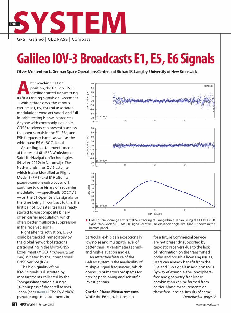
After reaching its final position, the Galileo IOV-3 satellite started transmitting
its first ranging signals on December 1. Within three days, the various carriers (E1, E5, E6) and associated modulations were activated, and full in-orbit testing is now in progress. Anyone with commonly available GNSS receivers can presently access the open signals in the E1, E5a, and E5b frequency bands as well as the wide-band E5 AltBOC signal.
According to statements made at the recent 6th ESA Workshop on Satellite Navigation Technologies (Navitec 2012) in Noordwijk, The Netherlands, the IOV-3 satellite, which is also identified as Flight Model 3 (FM3) and E19 after its pseudorandom noise code, will continue to use binary offset carrier modulation — specifically BOC(1,1) — on the E1 Open Service signals for the time being. In contrast to this, the first pair of IOV satellites has already started to use composite binary offset carrier modulation, which offers better multipath suppression in the received signal.
Right after its activation, IOV-3 could be tracked immediately by the global network of stations participating in the Multi-GNSS Experiment (MGEX; http://www.igs.org/mgex) initiated by the International GNSS Service (IGS).
The high quality of the IOV-3 signals is illustrated by measurements collected by the Tanegashima station during a 10-hour pass of the satellite over Japan (see Figure 1). The E5 AltBOC pseudorange measurements in
particular exhibit an exceptionally low noise and multipath level of better than 10 centimeters at mid- and high-elevation angles.
An attractive feature of the Galileo system is the availability of multiple signal frequencies, which opens up numerous prospects for precise positioning and scientific investigations.
Carrier-Phase MeasurementsWhile the E6 signals foreseen
for a future Commercial Service are not presently supported by geodetic receivers due to the lack of information on the transmitted codes and possible licensing issues, users can already benefit from the E5a and E5b signals in addition to E1. By way of example, the ionosphere-free and geometry-free linear combination can be formed from carrier-phase measurements on these frequencies. Results of some
galileo iOV-3 Broadcasts e1, e5, e6 SignalsOliver Montenbruck, German Space Operations Center and Richard B. Langley, University of New Brunswick
PRN E19
2012/12/03
3.Dec3h 6h 9h
-2.0
-1.5
-1.0
-0.5
0.0
0.5
1.0
1.5
2.0
MP(E1 BOC) [m]
2012/12/03
3.Dec3h 6h 9h
GPS Time [s]
0
10
20
30
40
50
60
70
80
90
Elev [deg]
2012/12/03
3.Dec3h 6h 9h
-2.0
-1.5
-1.0
-0.5
0.0
0.5
1.0
1.5
2.0
MP(E5 AltBOC) [m
]
Continued on page 27
SySteMthe
▲ Figure 1 Pseudorange errors of IOV-3 tracking at Tanegashima, Japan, using the E1 BOC(1,1) signal (top) and the E5 AltBOC signal (center). The elevation angle over time is shown in the bottom panel.


Lift Lift TiltTilt
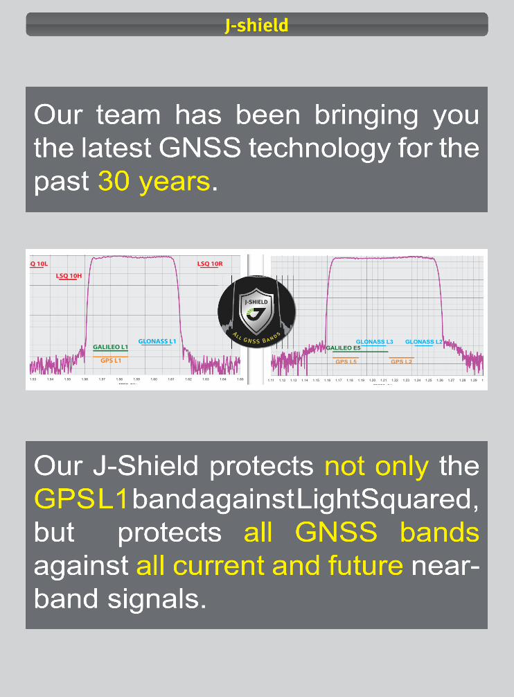
1.53 1.54 1.55 1.56 1.57 1.58 1.59 1.60 1.61 1.62 1.63 1.64 1.65
FREQ, GHz
LSQ 10L LSQ 10R
LSQ 10H
GALILEO L1
GPS L1
GLONASS L1
1.11 1.12 1.13 1.14 1.15 1.16 1.17 1.18 1.19 1.20 1.21 1.22 1.23 1.24 1.25 1.26 1.27 1.28 1.29 1
FDREQ, GHz
GLONASS L2GLONASS L3GALILEO E5
GPS L5 GPS L2
All
G NSS
Band
s
J-SHIELD
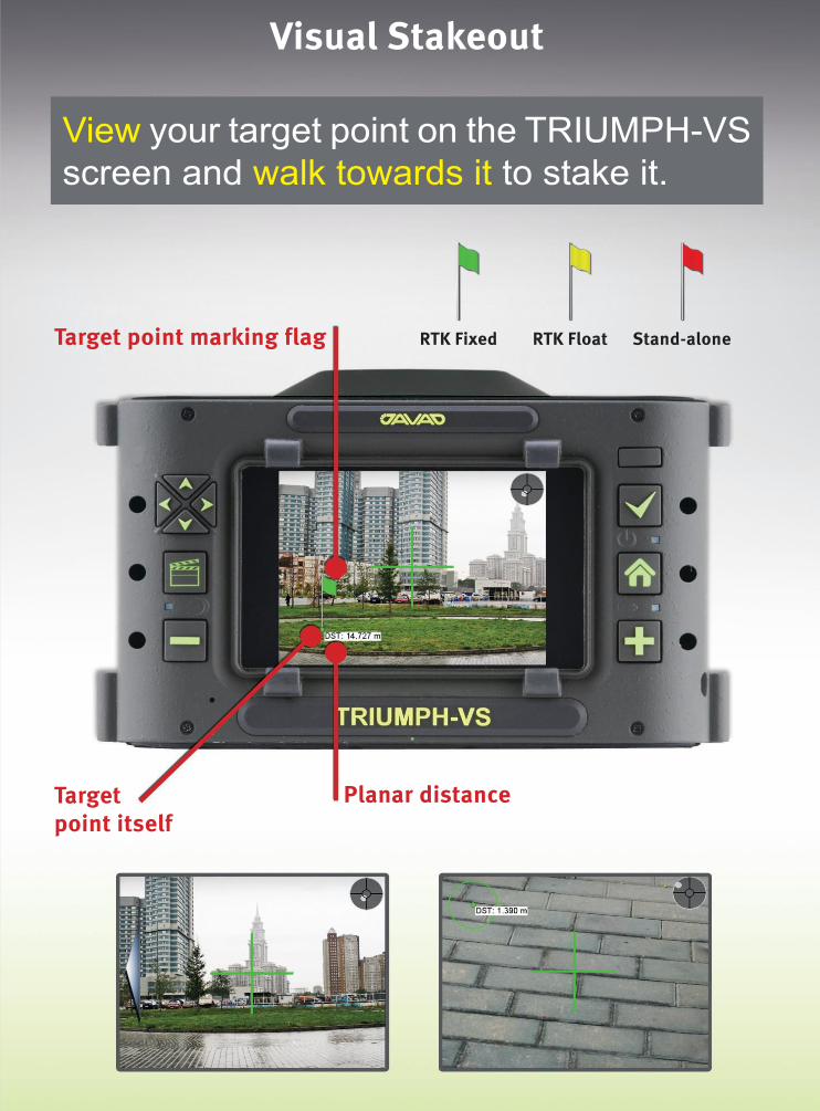
View your target point on the TRIUMPH-VS
screen and walk towards it to stake it.


your GNSS

www.gpsworld.com January 2013 | GPS World 27
the SyStem
first tests using this combination for IOV-3 are shown in Figure 2, based on measurements made at four MGEX stations: CUT0 (Perth, Australia), GMSD (Tanegashima, Japan), KZN2
(Kazan, Russia), and SIN1 (Singapore). The results provide an indication
of carrier-phase noise and multipath effects but are free of long-term variations that have earlier been found in GPS L1/L2/L5 signal combinations.
It is anticipated that similar measurement quality will be
obtained with the E1 and E5 signals of IOV-4, which were activated on December 12 and 13.
This level of performance highlights the potential benefit of Galileo signals in advanced triple-frequency techniques such as undifferenced ambiguity resolution and ionospheric monitoring.
CUT0 GMSD KZN2 SIN1
2012/12/02
21h3.
3h 6h 9h
-0.10-0.08-0.06-0.04-0.020.000.020.040.060.080.10
IF(L1X,L5X)-(L1X,L7X) [m]
Continued from page 18
Galileo E1, E5, E6
▲ Figure 2 The difference between the ionosphere-free carrier-phase combinations formed from E1/E5a and E1/E5b signals received at four MGEX stations: CUT0 (Perth, Australia), GMSD (Tanegashima, Japan), KZN2 (Kazan, Russia), and SIN1 (Singapore).
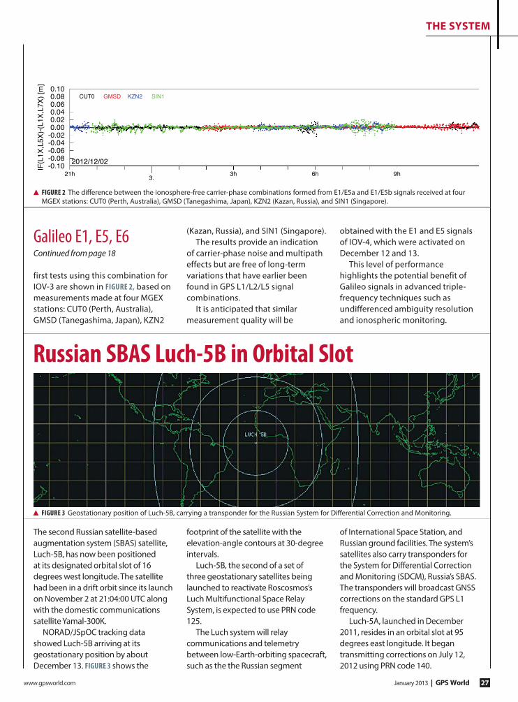
russian SBAS Luch-5B in Orbital Slot
The second Russian satellite-based augmentation system (SBAS) satellite, Luch-5B, has now been positioned at its designated orbital slot of 16 degrees west longitude. The satellite had been in a drift orbit since its launch on November 2 at 21:04:00 UTC along with the domestic communications satellite Yamal-300K.
NORAD/JSpOC tracking data showed Luch-5B arriving at its geostationary position by about December 13. Figure 3 shows the
footprint of the satellite with the elevation-angle contours at 30-degree intervals.
Luch-5B, the second of a set of three geostationary satellites being launched to reactivate Roscosmos’s Luch Multifunctional Space Relay System, is expected to use PRN code 125.
The Luch system will relay communications and telemetry between low-Earth-orbiting spacecraft, such as the the Russian segment
of International Space Station, and Russian ground facilities. The system’s satellites also carry transponders for the System for Differential Correction and Monitoring (SDCM), Russia’s SBAS. The transponders will broadcast GNSS corrections on the standard GPS L1 frequency.
Luch-5A, launched in December 2011, resides in an orbital slot at 95 degrees east longitude. It began transmitting corrections on July 12, 2012 using PRN code 140.
▲ Figure 3 Geostationary position of Luch-5B, carrying a transponder for the Russian System for Differential Correction and Monitoring.

GPS World | January 2013 www.gpsworld.com28
THE SYSTEM
The Intelligent Transport Systems (ITS) World Congress in Vienna this fall drew attention to the multi-constellation advantages provided by Galileo during a session on eCall, the European initiative for safer mobility. “Galileo will provide accuracy and reliability in all the transport markets, but in the case of emergency rapid assistance, the positioning need is even more critical,” said Fiammetta Diani, market development officer at the European GNSS Agency (GSA).
A multiconstellation approach for eCall and similar initiatives will deliver better performance without additional costs. Yaroslav Domaratsky from NIS-GLONASS, the Russian national navigation services provider, confirmed that ERA-GLONASS, the Russian version of eCall, will benefit from multiconstellation. “Solutions including also Galileo are welcome in the Russian initiative.”
Satellite ITS applications in road transport cover much more than in-car navigation. They include road-user charging with satellite-based toll collection systems; in-vehicle dynamic route guidance for drivers; intelligent speed adaptation to control the speed of vehicles externally; traveller information systems; and fleet-tracking systems for better management of freight movements and goods delivery.
Road TollingEuropean road-toll operators outlined how they plan to emply the European Geostationary Navigation Overlay Service (EGNOS) and Galileo to provide new tolling solutions.
Luigi Giacalone, managing director of Autostrade Tech, which provides the technology for the French Ecomouv project, said EGNOS will contribute to reliably collect taxes on the heavy trucks using the road charging scheme. “This is a tax, not a toll. It aims to collect a new tax reliably and fairly according
to distance travelled, while dissuading fraud,” he said. “Thanks to GNSS multi-constellation, only 10 locations out of the 15,000-kilometer network need support beacons.”
Ecomouv, which Includes anti-jamming and anti-spoofing mechanisms, covers 600,000 French lorries and 200,000 foreign ones, and will run from July 2013 for 11.5 years. Giacalone said its performance target was 99.75 percent accuracy of the entire collection chain, and its trials had already 99.8 percent accuracy.
Miroslav Bobošík from SkyToll, which operates Slovakia’s electronic tolling operations, explained how the system was able to cover not only 570 kilometers of motorways, but also 1,800 kilometers of first class roads in the country. “We needed a flexible system to cover different roads in different circumstances. And also to be fair to drivers, so they pay only for what they use,” said Bobošík. “We cover all services, not just toll collection, but enforcement, and technological maintenance and repair.”
GNSS tolling means flexibility as well as feasibility for SkyToll: since its launch in mid-2010, many changes have been made to the operation of the network, but thanks to the technology, they were easy to make. And they were cheap, he said. “While it is difficult to compare costs with other country, SkyToll has the lowest cost per kilometer to operate,” he said. “GNSS is the best possible solution for electronic tolling system in Slovakia, and GNSS is the most suitable for ITS.”
Changing the GameVolker Vierroth from T-Systems, the German IT services subsidiary of Deutsche Telekom, explained GNSS’s game-changing role: the availability of a huge variety of additional data linked to actual positions; more computing power, notably mobile and cloud-based; fast and reliable networks
available now with broad coverage, most recently with the shift from 3G to 4G; and smartphones, powerful and versatile, surging to the fore.
“GNSS [in the form of EGNOS] has proved to be a reliable technology for large-scale road charging on complex networks,” he said. “Galileo will bring further improvements, and may become the cornerstone of future road applications.”
EGNOS and Galileo in Emergency Call, Road Tolling
Compass ICD RumoredAs this magazine goes to press, unconfirmed reports from Shanghai state that the Compass Interface Control Document (ICD) will be released on Decembe 27.
Such rumors surfaced in late 2010 and again in late 2011. An October, 2011 GPS World newsletter reported “The long-awaited signal ICD for China’s growing GNSS will appear this month, according to representatives of the system who spoke in a “Compass: Progress, Status, and Future Outlook” workshop in September [2011].
“The ICD has been rumored to be available previously to receiver manufacturers within China, creating some disgruntlement among companies outside the country. A workshop panelist affirmed that GPS/Compass chips and receivers are being actively developed by many Chinese manufacturers and research institutes.”

www.gpsworld.com January 2013 | GPS World 29
Locata Tests Lead to Air Force ContractThe U.S. Air Force (USAF) signed a sole-source, multi-year, multi-million dollar contract with Locata Corporation to install a ground-based LocataNet positioning system at the White Sands Missile Range in New Mexico. The USAF will field Locata’s technology for reference-truth positioning across a large area of White Sands when GPS is being completely jammed.
In a recent USAF technical report, the need for a new non-GPS based positioning capability was described by the 746th Test Squadron as the key component for “the realization of the new ‘gold standard truth system’ for the increasingly demanding test and evaluation of future navigation systems for the U.S. Department of Defense.” The Air Force has now contracted with Locata to provide this capability for the USAF’s future truth
reference, the Ultra High-Accuracy Reference System (UHARS).
The report documented extensive testing of a LocataNet covering 1,350 square miles (3,500 square kilometers) deployed at White Sands. The USAF and the 746th Test Squadron proved a LocataNet can accurately position USAF aircraft over a large area when GPS is denied. Locata delivered accurate independent positioning as good as, or better than, the USAF’s current CIGTF Reference System (CRS). The Locata non-GPS based positioning capability is core to the UHARS that will replace the CRS in 2014.
After aircraft testing, the USAF concluded that the Locata system had not only met the demanding contractual tracking and positioning requirements, but actually exceeded them on many points. Some of the
milestones documented by the USAF included:◾ LocataNet position accuracy of 2.5
inches (6 centimeters) horizontally and 6 inches (15 cm) vertically for aircraft flying at a distance of 30 miles (50km) at up to 350 mph (550 km/hr) at 25,000 feet, without GPS.
◾ Throughout the period of the testing, the entire White Sands network achieved nanosecond-accurate synchronization within several minutes of the LocataNet being activated, and remained synchronized even during severe weather until turned off at the end of each test.
◾ By attaching a simple10 watt amplifier, the USAF proved that Locata signals could be acquired and tracked by aircraft at distances
▲ GooGle earth depiction of the USAF LocataNet test bed deployed at the White Sands Missile Range.
Industry news and developments | GPS | Galileo | GLONASS
BUSINESSthE
Continued on page 30

GPS World | January 2013 www.gpsworld.com30
the business
Raytheon UK has been awarded a contract by the UK Ministry of Defence for delivery of a new GPS anti-jam antenna land system. The contract is for an undisclosed number of advanced systems for deployment in operational theaters spanning multiple vehicle platforms. This UOR
(Urgent Operational Requirement) contract is the first award for Raytheon’s GPS Anti-Jam (AJ) Land product family. Raytheon UK has delivered more than 7,000 units for air and naval capabilities in the UK and U.S., according to Bob Delorge, chief executive, Raytheon UK.
The contract will see the deployment of the systems under a very short timescale, with final delivery of the capability expected to be completed six months from contract award.
Raytheon UK is a subsidiary of Raytheon Company.
Raytheon UK Wins Contract for GPS Anti-Jam System
» fleet trackinG
Navman Wireless is offering two professional services packages to expedite, optimize and provide problem resolution for 100-plus-vehicle implementations of its OnlineAVL2 fleet management platform. The new services are designed to reduce rollout and configuration time by up to 80 percent, produce a 50 percent faster return on investment, and help corporate and construction fleet managers derive maximum value from the system by doubling the number of features used.
Both the Standard and Turnkey professional services bundles entitle customers to a dedicated project and account team, including a field services
engineer serving as a single point of contact and project manager, plus the use of a dedicated phone line staffed with support specialists assigned exclusively to handle larger accounts.
The Standard package includes installation support, basic OnlineAVL2 configuration, a training website and weekly group training webinars, priority issue escalation, and a yearly account review to evaluate the customer’s use of the system and identify opportunities to realize greater benefits from the deployment.
The Turnkey package includes all Standard features plus 80 hours of project management time for on-site project planning and user training
as well as weekly update calls and advanced OnlineAVL2 configuration for features such as geofences, maintenance module setup, report scheduling, and email and text alerts. This premium package also includes ongoing best practice guidance, regular on-site business reviews, API-based integration into backend systems, and guaranteed 45-day implementation with appropriate advanced notice and asset availability.
Optional add-on services include custom training and documentation, installation and training at additional depots or terminals, and project management for complex implementations.
» defenSe
of up to 60 miles (100 km). Longer distances could be enabled by attaching higher-powered amplifiers.
◾ The Locata system functioned under dynamic aircraft operating maneuvers, including banking, angular and linear accelerations, airspeeds up to 300 knots (560 km/hr), and altitudes up to 30,000 feet above sea level.
◾ The USAF required Locata to design, prototype, and deliver aircraft-certified antennas for use on both the Locata ground-based transmitters and the USAF aircraft. Locata worked with Cooper Antennas Ltd. of Marlow in Buckinghamshire, United Kingdom, to produce an aircraft-certified version of Locata’s quadrifilar helix antenna design. Under the new contract, Locata
will provide the USAF with Locata
receivers and LocataLite transmitters to blanket 2,500 square miles (6,500 sq km) of the White Sands Range. Locata will also deliver extended hardware warranty, along with ongoing Locata software and firmware upgrades, to the year 2025; and provide long-term consultation and expert technical advice to ensure optimal operational performance of the USAF’s fielded LocataNet systems.
LocataContinued from page 29
Navman Wireless Debuts Professional Services for Fleet Tracking
www.gpsworld.com January 2013 | GPS World 31
the business
Munich Navigation Satellite SummitChange of Dates: now June 18–20, Munich, Germanywww.munich-satellite-navigation-summit.orgAn announcement arriving at press time states that the Munich Summit will move from its previous February dates to June 18–20 instead. The Summit features invited high-ranking speakers from industry, science, and governments dealing with the directions of satellite navigation now and in the future.
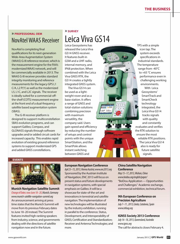
European Navigation ConferenceApil 23–15, 2013, Vienna Austria; www.enc2013.orgSponsored by the Austrian Institute of Navigation, ENC 2013 will focus on present status and future developments in navigation systems, with special emphasis on Galileo. It will be a showcase for state-of-the-art and innovations in terrestrial and satellite navigation. The implementation of new technologies will be illustrated by the industry exhibition, running in parallel to the conference. Status, Development, and Interoperability of GNSS; Certification and Standardization; Receiver and Antenna Technologies; and more.
China Satellite Navigation ConferenceMay 15–17, 2013, Wuhan, Chinawww.beidou.org/english/paper/“BeiDou Application — Opportunities and Challenges.” Academic exchange, commercial exhibition, technical forum.
9th European Conference on Precision AgricultureJuly 7–11 , 2013; Lleida, Catalonia, Spainwww.infoag.org
IGNSS Society 2013 ConferenceJuly 16–18, 2013, Queensland, Australiawww.ignss.orgThe call for abstracts closes February 4.
Leica Geosystems has released the Leica Viva GS14 GNSS receiver. It features built-in GSM and a UHF radio, internal memory, and IP68 protection. When combined with the Leica Viva GNSS RTK, the GS14 creates a tightly integrated GNSS system.
The Viva GS14 can be used as a light-weight rover and as a base station. It offers a range of GNSS and total-station solutions combining precision with maximum versatility, the company said. Users gain speed and efficiency by reducing the number of setups and control points with the unique SmartStation, and the SmartPole allows instant switching between GNSS and
TPS with a simple icon tap. The system exceeds specifications in
industrial standards. The temperature range from -40°C to +65 °C ensures performance even in challenging working environments.
With Leica Geosystems’ SmartTrack and SmartCheck technology integrated, the Leica Viva GS14 tracks signals with quality and constantly
evaluates and verifies the RTK solution to ensure the most
reliable RTK positions. The Leica Viva GS14 also is ready for future satellite signals.
» SurvEy
Leica Viva GS14
» EvENtS
» ProfESSIoNAl oEM
NovAtel is completing final qualifications for its next-generation Wide-Area Augmentation System (WAAS) G-III reference receiver, which is the measurement engine for the FAA’s modernized WAAS network, and will be commercially available in 2013. The WAAS G-III receiver provides standard integrity monitoring and reference measurements for the legacy GPS L1 C/A, L2 P(Y) as well as the modernized L5, L1C, and L2C signals. The receiver is ideally suited for a commercial-off-the-shelf (COTS) measurement engine at the front end of a dual-frequency satellite based augmentation system (SBAS).
The G-III receiver platform is designed to support multiconstellation SBAS evolution programs, and can support Galileo, Compass, and GLONASS signals through software upgrades and/or added circuit cards for increased capacity. This enables rapid evolution of existing ground reference systems to support modernized GPS and added GNSS constellations.
NovAtel WAAS Receiver

GPS World | January 2013 www.gpsworld.com32
the business
Mobile Storefronts Distribute 81 Billion Apps» LOCATION-bASed ServICeS
Alberding GmbH, a developer and distributor of professional GNSS system solutions, will be offering its Alberding A07 personal navigator featuring NVS Technologies AG’s NV08C-CSM high-performance multi-GNSS constellation receiver. The Alberding A07 is a low-cost single-frequency GNSS receiver designed for personal navigation and other sub-meter accuracy positioning applications in an urban environment.
The device integrates NVS
Technologies’ NV08C-CSM multi-constellation (GPS, GLONASS, Galileo, COMPASS, and SBAS) L1 receiver with GPRS and Bluetooth communication modules, an RFID reader, and a processor. The Alberding A07 comes with an integrated GNSS antenna, but for monitoring and tracking applications, it is also available with an external antenna.
Applications include: pedestrian navigation and tracking; navigation for the visually impaired; RFID-based indoor positioning; transportation;
GIS data collection; and displacement monitoring and alarming.
The Alberding DGNSS processing algorithm and Kalman filter take raw GNSS observation data to compute a highly accurate position solution in real time. Position information can then be transmitted via Bluetooth to custom-specific applications running on devices such as smartphones. For example, the Alberding A07 can assist blind or visually impaired people with orientation and navigation on the streets.
NVS Technologies Selected by Alberding for Sub-Meter GNSS Receiver» PrOfeSSIONAL Oem
China Industry Report: Growth in Mobile Market» LOCATION-bASed ServICeS
A new China Navigation Map Industry Report, 2012-2014, released by Sino Market Insight, predicts that the revenue of Chinese navigation electronic map industry will reach RMB 2.1 billion ($334 million) in 2014.
Started in 2002, the navigation industry in China is still in the initial stage of development compared with the international market, the report says. China’s car navigation market,
PND navigation market and mobile phone navigation market are in the stage of rapid development, while the markets of LBS service, real-time traffic information service, and value-added electronic map application services based on mobile communication technology are still in the initial stage of development.
From 2006 to 2011, the sales volume of car navigation in China maintained
high-speed growth, with CAGR hitting 47.5 percent. However, the penetration rate of car navigation is still low, so China’s car navigation market still has huge growth potential. Meanwhile, the growth speed of GPS mobile phone market in China is amazing, the report says. The sales volume of GPS mobile phone in China approximated 100 thousand sets in 2006, and skyrocketed to more than 50 million sets in 2011.
Mobile application storefronts had collectively distributed a cumulative total of 81 billion smartphone and tablet apps as of the end of September 2012, according to a recent market study from ABI Research. Of these, 89 percent were downloaded from native storefronts that come with the device’s operating system.
“The current status quo is based on storefronts that the operating system
vendors provide as part of the OS experience, and there is no evidence that this would change in the future,”
said ABI Research senior analyst Aapo Markkanen. “A year ago it still looked like that, for example, mobile operators could find a viable business case in the curation of Android apps, but that opportunity evaporated once Google got its storefront act together. Today, it makes sense for operators to distribute apps only under special circumstances, such as the ones that we’re seeing in China.”

www.gpsworld.com January 2013 | GPS World 33
the business
Apple iPad owners can now read GPS World on their devices, through a free application that provides an interactive version of the magazine at your touchtip, with access to digital back issues, and an RSS feed of latest industry news.
Downloading the app is free and simple. Search “GPS World” in the App Store, or go to http://itunes.com/apps/GPSWorldHD.
» location-baSed ServiceS
Trimble Outdoors Elite membership program provides access to more than 2,500 topo map bundles that can be stored on smartphones and tablets, and used with other provided tools.
The program caters to hikers, backpackers, and off-roaders, with a smartphone app (iPhone, Android) and tablet app (iPad, Android, Kindle Fire) . Membership includes: ◾ offline topographic maps of
remote areas, in large swathes, storable on mobile devices, bundled by state, county or park—more than 2,500 areas across the United States These map files are dragged-and-dropped onto a SD memory card or into an iTunes account then transferred to the phone or tablet.
◾ Public Lands: With the U.S. patchwork of private and public lands, it’s important to know where the boundaries are and whether the land is under private or public ownership.
◾ Weather Maps: Before heading out the door, members can check interactive weather maps to see what clothing/gear to pack or whether to change their itinerary. Zoom in on exact areas for real-time weather overlays, including Doppler radar, satellite images, wind speed, and temperature.
◾ Printed Maps: Search-and-rescue experts advise outdoor enthusiasts not to depend solely on electronics in the field.
◾ Trip Planner to draw routes and mark waypoints.
Trimble Outdoor Mapping for Fresh-Air Enthusiasts
Telit Wireless Solutions has introduced the Jupiter SE880 ultra-compact GPS receiver module for applications in the commercial, industrial, and consumer segments including wearable and handheld devices. The miniature 4.7 x 4.7 millimeter land grid array, SiRFstarIV-based receiver module employs 3D component embedding technology to achieve performance in all dimensions critical for regular or size-constrained GPS applications. The SE880 receiver module was conceived to shorten time-to-market and to make the chipset-versus-module decision an easy one to make for device integrators. Integrators can attain a working SE880-based design in as little as a week versus several months when starting
from a chipset reference design.
The Jupiter SE880 includes all components necessary for a fully functioning receiver design, requiring only a 32-KHz external
crystal for its time-base and TCXO to complete the design, along with antenna, power and data connections adequate to the integrator’s needs, the company said. For advanced designs incorporating the supported satellite based augmentation system (SBAS), ephemeris data collected from the satellites can be stored to SPI Flash memory instead of the more common and expensive alternative of the EEPROM — again reducing costs and improving the business case for the end-device.
» conSumer oem
Telit Receiver Based on 3D Embedded Technology
» PerSonal trackinG
u-blox runs inside MobileHelp, a provider of M-PERS (Mobile-Personal Emergency Response System) technology. Based on u-blox’ LISA 2G/3G wireless modem and MAX GPS modules, the system includes compact, portable alert devices that function in and around the home, and while traveling. Unlike traditional 911 services, MobileHelp devices deliver instant position information as well as personalized medical data to an emergency response center at the touch of a button.
The system is integrated with nationwide wireless voice, data and GPS for real-time medical monitoring services, location tracking, and instant voice contact with trained emergency response operators; also offers caregiver tools.
u-blox Medical Alert
There’s an App for This

Apply the power of place at www.geospatial-solutions.com.
APPLYING THE POWER OF PLACE
www.geospatial-solutions.com
gives you the edge in a rapidly expanding industry.
The resource for GIS — geographic information systems.
BETTER THAN EVER!!In the biggest market ever.
Sourc
e: Tom
Tom
Sourc
e: U
SG
S
Eric Gakstatter, Survey editor for GPS World, produces
www.geospatial-solutions.com, the Geospatial Solutions Weekly
enewsletter, frequent webinars, and a Twitter newsfeed with the latest news,
analysis, and trends in the expanding geospatial industry: software, services and data.
The GIS industry rang up $5 billion in 2011, and will grow to $10.6 billion by 2015.
Keep up with this growing market. Get ahead of it with expert analysis!
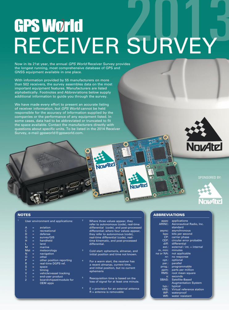
Now in its 21st year, the annual GPS World Receiver Survey provides
the longest running, most comprehensive database of GPS and
GNSS equipment available in one place.
With information provided by 55 manufacturers on more
than 502 receivers, the survey assembles data on the most
important equipment features. Manufacturers are listed
alphabetically. Footnotes and Abbreviations below supply
additional information to guide you through the survey.
We have made every effort to present an accurate listing
of receiver information, but GPS World cannot be held
responsible for the accuracy of information supplied by the
companies or the performance of any equipment listed. In
some cases, data had to be abbreviated or truncated to fit
the space available. Contact the manufacturers directly with
questions about specific units. To be listed in the 2014 Receiver
Survey, e-mail [email protected].
abbreviations
apps: applications
ARINC: Aeronautical Radio, Inc.
standard
async: asynchronous
bps: bits per second
CP: carrier phase
CEP: circular error probable
diff: differential
ext.: external / int. = internal
m, min: minutes
na or NA: not applicable
nr: no response
opt.: optional
par.: parallel
prog.: programmable
ppm: parts per million
RMS: root mean square
s: seconds
SBAS: Satellite-Based
Augmentation System
typ.: typical
VRS: Virtual reference station
WP: waterproof
WR: water resistant
notes1 User environment and applications: 2 Where three values appear, they
refer to autonomous (code), real-time
differential (code), and post-processed
differential; where four values appear,
they refer to autonomous (code),
real-time differential (code), real-
time kinematic, and post-processed
differential.
3 Cold start: ephemeris, almanac, and
initial position and time not known.
4 For a warm start, the receiver has
a recent almanac, current time,
and initial position, but no current
ephemeris
5 Reacquisition time is based on the
loss of signal for at least one minute.
6 E = provision for an external antenna
R = antenna is removable
A = aviation
C = recreational
D = defense
G = survey/GIS
H = handheld
L = land
M = marine
Met = meteorology
N = navigation
O = other
P = other position reporting
R = real-time DGPS ref.
S = space
T = timing
V = vehicle/vessel tracking
1 = end-user product
2 = board/chipset/module for
OEM apps

GPS World | January 2013 www.gpsworld.com2
Beyond General Receiver Specifications
The in-depth specifications presented in this GNSS receiver survey are critical for making the correct purchase decision,
however specifications must always be considered in relation to the demands of your application. Buyers must consider matters of size, weight, accuracy and availability and weigh them in light of other factors such as cost and ease of integration.
As well, certain aspects of a GNSS receiver’s functionality may not be directly comparable by considering receiver specifications alone. When choosing your GNSS provider, consider the following to ensure you optimize your GNSS receiver purchase
Absolute Accuracy versus Relative AccuracyThe receiver survey displays the absolute positioning accuracy of the various receivers, but for some applications this is not the only quality that matters. In traditional GNSS applications such as surveying, absolute position accuracy is
critical. Precision farming and machine automation require position
output that is also very stable over time. GNSS
position accuracy can vary over time with changes in satellite visibility or when the receiver changes
between correction types. These changes can result in
position solution discontinuities. Receivers vary greatly in how they
deal with these shifts. When choosing a receiver for your application, enquire about the receiver’s relative position stability to ensure that the receiver will suit your application. NovAtel’s GL1DE® and mode-match algorithms are specially designed to ensure the position from the receiver is as smooth as possible, regardless of the challenges presented by the operating environment.
Heading and Orientation DeterminationGNSS are by their nature position
determination systems. However many applications such as excavating and drilling, aircraft and marine vessel navigation, mobile or airborne mapping require accurate orientation information as well, which single-antenna GNSS systems cannot easily provide. Direction of travel can be used as an approximation of heading, but true vehicle heading, roll and pitch must be derived using an alternate approach.
There are multiple ways to work around this limitation of GNSS. Heading can be determined by measuring the 3D offset between two or more GNSS antennas fixed to a vehicle. For environments where the GNSS signal availability is good, these systems can give a very accurate measurement of the heading and pitch of a vehicle. GNSS heading products like NovAtel’s ALIGN® technology can be easily deployed onto a vehicle to provide heading for a range of applications.
Inertial sensors (gyroscopes and accelerometers) can also be used along with GNSS to compute a 3D attitude solution (roll, pitch, heading). GNSS/INS systems have the advantage of computing attitude and also of improving the position reliability of the GNSS receiver. NovAtel’s tightly-coupled SPAN® GNSS/INS technology is available on all our OEM6™ receivers. SPAN offers a range of IMUs to suit many applications requiring high-rate, robust positioning and precise attitude.
Raw Data for Post-ProcessingHigh precision applications usually rely on post-mission processing of the GNSS data. GNSS post-processing offers many advantages over real time operation. If a real time solution is not required, the raw GNSS measurement data can be collected in the field and processed post-mission to provide a precise position and velocity solution. Post-processing allows for simplified real time system operation without the need for real time telemetry and allows lower cost receiver hardware to be used. There are publicly available reference station data or precise satellite clock and orbit data for precise point positioning (PPP). When choosing a receiver, consider how the data
James Hamilton
ADVERTORIAL
p
b
www.gpsworld.com January 2013 | GPS World 3
1. Does your vendor compete with you in your market? A true OEM supplier will support you in winning market share in your market and not show up at your customer with their product.
2. Does your vendor have a track record for GNSS innovation and leading-edge technology?
3. Integrating a receiver into your system can be a complex activity. Is your vendor set up to support you with the integration effort? Is the product well documented and designed for integration? Does the company have a support structure of application engineers capable with assisting with integration challenges?
4. Is your vendor a reliable and recognized manufacturer? As receivers become more complex, only proven manufacturers will succeed in offering high product quality and reliability.
5. Is your vendor a cooperative part of your supply chain? Your vendor should support your needs with quick lead times and flexible order fulfillment. NovAtel’s field-upgradeable products allow customers to keep their inventory costs low and offer product flexibility.
6. Is your vendor financially stable? The recent recession has been difficult for the GNSS industry. Make sure your vendor is likely to be around to support you with your current product — and to develop innovative, next-generation technology.
Choosing the right vendorJust as there are technical considerations for choosing the right receiver, there are factors that should influence whom you choose as your GNSS partner. Some questions to consider include:
processing will fit into your overall workflow. An easy to use and easy to integrate software package can make all the difference. NovAtel’s Waypoint® post-processing packages support GNSS and GNSS/INS processing with a simple, yet extremely flexible user interface.
Antenna SelectionChoosing the correct GNSS antenna is vital to GNSS system performance. A high performance GNSS antenna provides superior multipath rejection and highly stable phase center, both important to precision operations. Matching the signals and frequencies between your antenna and receiver is critical. If your vendor has an antenna product-line, they can help fit the right antenna to the application.
With all spectrums of signals being utilized with modern GNSS, intentional and unintentional interference and jamming is becoming major concern. Anti-jamming antennas such as NovAtel’s GAJT™ mitigate the threat to military operations, timing and networks infrastructures.
Ease of IntegrationIntegration factors to be considered before you buy include:
• Scalability:Areceivershouldhaveascalablelevel
of performance so that it can evolve as your needs change. In this way by integrating one receiver, a range of different applications can be satisfied with only a change of software.
• InterfaceProtocols:Thesurveyidentifiesthe
communication options available with the listed receivers. It is also important to make sure the receiver you choose has the interface protocols you need for your application.
• ComplementaryTechnology:SomeGNSSreceivers
can be paired easily with other sensor devices to provide position and velocity solutions with higher precision and quicker update rates. These sensors includes: accelerometers, gyroscope, and odometer etc.
My interview in the 2011 GPS World GNSS Receiver Survey provided additional information and advice regarding the tradeoffs often required when choosing a receiver. This information can be found on the NovAtel website at novatel.com/assets/Documents/Articles/Excerpt-from-2012GPSWorldReceiverSurvey.pdf.
GNSS product information or integration advice can also be obtained by clicking on the “Get Expert Advice” button found throughout novatel.com.
A receiver should have a scalable level of performance so that it cn evolve as your needs change.
ADVERTORIAL

receiver survey 2013 | Sponsored by
GPS World | January 2013 www.gpsworld.com4
Manufacturer Model Channels/tracking
mode
Signal tracked Maximum number of
satellites tracked
User environment and
application 1
Size (W x H x D) Weight Position: autonomous (code) / real-
time differential (code) / ; real-time
kinematic/post-processed 2
Time
(nanosec)
Position Àx update
rate (sec)
Altus Positioning Systems
www.altus-ps.com
APS-3 136 par. GPS+GLONASS L1, C/A & CP; L2, P-code & CP;
L2C; WAAS/EGNOS
All in View GPS +
GLONASS
GLMNOPRV1 17.8 (Ø) x 9.0cm <1.3 kg 1.3m/0.5m/1cm+1ppm/2mm+0.5ppm
(1-sigma)
10 0.04
APS-3G 136 par. GPS L1, C/A L2, P-code & CP; L2C; L5 code &
CP, GALILEO L1 code & CP; E5a code & CP;
WAAS/EGNOS
All in View GPS +
GLONASS + GALILEO
GLMNOPRV1 17.8 (Ø) x 9.0cm <1.3 kg 1.3m/0.5m/1cm+1ppm/2mm+0.5ppm
(1-sigma)
10 0.04
APS-3L 136 par. GPS L1, C/A L2, P-code & CP; L2C; L5 code &
CP, GALILEO L1 code & CP; E5a code & CP;
WAAS/EGNOS
All in View GPS +
GLONASS + GALILEO
GLMNOPRV1 17.8 (Ø) x 9.0cm <1.3 kg 1.3m/0.5m/1cm+1ppm/2mm+0.5ppm
(1-sigma)
10 0.04
APS-U 136 par. GPS L1, C/A L2, P-code & CP; L2C; L5 code &
CP, GALILEO L1 code & CP; E5a code & CP;
WAAS/EGNOS
All in View GPS +
GLONASS + GALILEO
GLMNOPRV1 17.7 x 16.7 x 4.8cm 1.6 kg 1.3m/0.5m/1cm+1ppm/2mm+0.5ppm
(1-sigma)
10 0.04
Ashtech / Boards & Sensors
www.ashtech-oem.com
MB 100 Board 45 par. GPS and GLONASS L1 C/A,; GPS L1/L2 P(Y)-
code, L2C, L1/L2 full wavelength carrier,; SBAS
code & carrier
12 GPS, 12 GLONASS,
3 SBAS
AGLMNOPRV2 2.3 x 2.2 x 0.4in 0.78 oz 3m/25cm+1ppm/1cm+1ppm/ 0.3cm
+ 0.5ppm
nr 0.05s
MB 800 Board 120 par. GPS L1 C/A L1/L2 P-code, L2C, L5- GLONASS
L1 C/A, L2 C/A code- GALILEO E1 and E5 -
SBAS L1 code and carrier (WAAS/EGNOS/
MSAS)- Fully inde
12 GPS, 12 GLONASS,
3 SBAS
AGLMMetNOPRV2 3.9 x 3.1 x 0.5 in 2.18 oz 3m/25cm+1ppm/1cm+1ppm/ 0.3cm
+ 0.5ppm
nr 0.05s
SkyNav GG12W
GPS+SBAS - FAA Certi¿able
Board
12 par. L1 only, C/A-code and carrier (GPS and SBAS) as above ADNO2 4.3 x 3.3 x 0.6in 3.8 oz 3m/1m/nr/5mm + 1 ppm nr 0.2s
HDS800 RTK+Heading
System
240 par. GPS L1 C/A L1/L2 P-code, L2C, L5- GLONASS
L1 C/A, L2 C/A code- GALILEO E1 and E5 -
SBAS L1 code and carrier (WAAS/EGNOS/
MSAS)- Fully inde
12 GPS, 12 GLONASS,
3 SBAS
AGLMMetNOPRV2 8.46x7.87x2.99 in 4.6 lb 3m/25cm+1ppm/1cm+1ppm/ 0.3cm
+ 0.5ppm
nr 0.05s
ADU5 3D Attitude Sensor 56 par./2 beacon L1 only, C/A-code and carrier, SBAS, Beacon 12GPS + 2 SBAS ADLMNOT1 8.5 x 3.75 x 7.7in 4.125 lb 3m/40cm/nr 200 0.2s
DG14 GPS+SBAS Board 12 GPS + 2 WAAS as above as above ADGLMNOPRSTV2 108 x 57mm 2.3 oz 3m/40cm/1cm + 1 ppm/1cm + 1 ppm 200 0.05s
ABX14 receiver 14 par. as above as above ADGLMNOPRTV1 8.70 in x 2.28 in x 6.30 in 2 lbs 15
ounces
as above 200 0.05s
ABX Series GNSS sensors 45, 120 or 240 par. GPS L1 C/A L1/L2 P-code, L2C, L5- GLONASS
L1 C/A, L2 C/A code- GALILEO E1 and E5 -
SBAS L1 (WAAS/EGNOS/MSAS/GAGAN)- QZSS
12 GPS, 12 GLONASS,
3 SBAS
AGLMMetNOPRV2 7.48x2.28x6.3 in 2.70 lb 2.5m/25cm+1ppm/1cm+1ppm/ 0.3cm
+ 0.5ppm
nr 0.05s
BAE Systems Rokar
www.baesystems.com
GPS SpaceNav 24 par. correlator GPS L1 C/A code, 24 GPS 12 - all in view S1 2.49 x 4.33 x 8.11in 1.4 kg 5m/na/na/na 150 1
BP GPS 12 par. Correlator L1 only, C/A–code 12 - all in view ADLNO2 4.72 x 0.63 x 4.82in 105 g 5m/na/na/na 300 1
NT4RLG GPS 12 par. Correlator L1 only, C/A–code 12 - all in view ADLNO2 4.72 x 0.63 x 4.82in 110 g 5m/na/na/na 300 1
GPS SWIFT-NT 24 par. L1 only, C/A–code 24 - all in view ADN1 3.72x2.52x10.37in 1.1 kg 5m/na/na/na 300 1
NAVPOD NT 12 par. L1 only, C/A–code 12 - all in view ADNOR1 3.72 x 1.20 x 7.00in 580 g 5m/na/na/na 300 1
NavComp 36 par. Correlator L1 GPS C/A–code, L1 Glonass 36 - all in view ADNOR1 5.60 x 2.70 x 6.61in 1.7 kg 5m/na/na/na 300 10
HNR-10 12 par. Correlator L1 only, C/A–code 12 - all in view ADNOT2 4.80x0.75x3.66in 150 g 5m/na/na/na 40 10
GH-C GPS 12 par. Correlator L1 only, C/A–code 12 - all in view ADNP2 2.5 in diameter 25 g 5m/na/na/na 300 1
GH-L GPS 12 par. Correlator L1 only, C/A–code 12 - all in view ADNP2 2.3 in diameter 40 g 5m/na/na/na 300 1
A/J SNIR GPS 24 par. Correlator L1 GPS C/A–code, L1 Glonass 24 - all in view ADNP2 2.49 x 4.33 x 8.11in 1.4 kg 5m/na/na/na 300 10
Baseband Technologies, Inc.
www.basebandtech.com
GPS/PC Pro user de¿ne GPS L1 C/A code user de¿ne ACDHLMNOPV12 na na ~5m na 500Hz
BTI-2800LP user de¿ne GPS L1 C/A code user de¿ne ACDHLMNOPV12 0.7 x 0.7cm < 1g ~5m na 500Hz
Broadcom
www.broadcom.com
BCM4751 12 GPS L1, SBAS, QZSS 12 NHC2 3 x 2.9mm < 1g 2m/1m/na/na (CEP) 50 1
BCM2076 12 GPS L1, GLONASS, SBAS 12 NHC2 4.28 x 3.83mm < 1g 2m/1m/na/na (CEP) 50 1
BCM47511 18 GPS L1, GLONASS, SBAS, QZSS 18 NHC2 2.85 x 3.02mm <1g 2m/1m/na/na (CEP) 50 1
BCM4761 12 GPS L1, SBAS 12 NHC2 11 x 11 x 1.2mm <1g 2m/1m/na/na (CEP) 50 1
BCM4752 >100 GPS L1, GLONASS, SBAS, QZSS, IMES >35 NHC2 2.0 x 2.4mm <1g 2m/1m/na/na (CEP) 50 1
CellGuide
www.cell-guide.com
ACLYS GPS/AGPS IC 80 ch. Up to 16 SV GPS L1 C/A All in View CHNV2 5.0 x 5.0 x 0.9mm 0.07g 3m, 3m, 3m, 5m na 1
ACLYS-M GPS/AGPS
Module
80 ch. Up to 16 SV GPS L1 C/A All in View CHNV2 13.0 x 16.0 x 1.97mm 0.6g 3m, 3m, 3m, 5m na 1
CLIOX-C GPS/AGPS+ 3D
Electronic Compass IC
80 ch. Up to 16 SV GPS L1 C/A All in View CHNV2 5.0 x 5.0 x 0.9mm 0.07g 3m, 3m, 3m, 5m na 1
CGsnap GPS/AGPS
Baseband IP
80 ch. Up to 16 SV GPS L1 C/A All in View CHNV2 na na 3m, 3m, 3m, 5m 100nS 1
CGsnap Pro GNSS/A-GNSS
Baseband IP
192 ch. Up to 30 SV GPS L1 C/A, GLONASS G1 All in View CHNV2 na na 3m, 3m, 3m, 5m 100nS 1
ACLYS-L RF Front End All in View GPS, GLONASS, GALILEO, COMPASS All in View CHNV2 5.0 x 5.0 x 0.9mm 0.07g na na na
Communication & Navigation (C&N)
www.c-n.at
TinyBrother GPS 24 GPS L1 C/A code & CP All-in-View AGLV1 73 x 37 x 116mm 250g 5m/<1m/n.a./n.a. <50ns 1Hz
CSR
www.csr.com
GSD4t 48 GPS L1 C/A, SBAS,QZSS 24 CHNV2 3.4 x 2.7 x 0.6mm na 10m/nr/nr/nr (95%) nr Variable
GSD4e 48 GPS L1 C/A, SBAS,QZSS 24 CHNV2 3.5 x 3.2 x 0.6mm na 10m/nr/nr/nr (95%) nr Variable
SiRFPrima Up to 64 GPS L1 C/A, SBAS,QZSS All in View CHNV2 16 x 16 x 1.1mm na 10m/nr/nr/nr (95%) nr Variable
SiRFPrima Automotive Up to 64 GPS L1 C/A, SBAS,QZSS All in View CHNV2 16 x 16 x 1.1mm na 10m/nr/nr/nr (95%) nr Variable
SiRFPrimaII Up to 64 GPS L1 C/A, SBAS, Glonass, Galileo,
Compass, QZSS
All in View CHNV2 17 x 17 x 1.1mm na 10m/nr/nr/nr (95%) nr Variable
SiRFPrimaII Automotive Up to 64 GPS L1 C/A, SBAS, Glonass, Galileo,
Compass, QZSS
All in View CHNV2 17 x 17 x 1.1mm na 10m/nr/nr/nr (95%) nr Variable
SiRFAtlasIV Up to 64 GPS L1 C/A, SBAS,QZSS All in View CHNV2 12 x 12 x 1.1mm na 10m/nr/nr/nr (95%) nr Variable
SiRFAtlasV Up to 64 GPS L1 C/A, SBAS,QZSS All in View CHNV2 10 x 13 x 1.2mm na 10m/nr/nr/nr (95%) nr Variable
SiRFAtlasVI Up to 64 GPS L1 C/A, SBAS, Glonass, Galileo,
Compass, QZSS
All in View CHNV2 13.4 x 12.6 x 1.16mm na 10m/nr/nr/nr (95%) nr Variable
SiRFstarV 5ea Automotive Up to 52 GPS L1 C/A, SBAS, QZSS, Glonass, Galileo,
Compass
24 CHNV2 7.00 x 10.00 x 1.2mm na 10m/nr/nr/nr (95%) nr Variable
5t Up to 52 GPS L1 C/A, SBAS, QZSS, Glonass, Galileo,
Compass
24 CHNV2 3.11x2.20x0.6 10m/nr/nr/nr (95%) nr Variable
DataGrid, Inc.
www.datagrid-international.com
Toughman 336 or more
depending on
con¿g
L1 full cycle CP, C/A–code, L2 full cycle CP, P2 or
L2C code, SBAS, option: GLONASS L1, full cycle
CP, C/A–code, L2 full cycle and L2 C/A code.
20 or more depending
on con¿g
GLMNOVR1 20 x 8.5 x 3.5cm 600g 1.5m/<1m /1cm/<1cm (RMS) <35 1,1/2,1/5, 1/10
Mk3 “Chameleon” 336 or more
depending on
con¿g
as above 20 or more depending
on con¿g
GLMNOVRT1 27 x 8.5 x 3.5cm 750 g 1.5m/<1m /1cm/<1cm (RMS) <35 1,1/2,1/5, 1/10
Gator 336 or more
depending on
con¿g
as above 30 or more depending
on con¿g
GLMNOVRT1 10 x 8.4 x 3.5cm 340 g 1.5m/<1m /1cm/<1cm (RMS) <35 1,1/2,1/5, 1/10, 1/20
Colibri 336 or more
depending on
con¿g
L1 full cycle CP, C/A–code, L2 full cycle CP, P2
or L2C code, SBAS, GLONASS L1, full cycle CP,
C/A–code, L2 full cycle and L2 C/A code.
30 or more depending
on con¿g
GLMNOVRT1 Ø 17cm x 10cm ~400 g
depending on
con¿g.
1.5m/<1m /1cm/<1cm (RMS) <35 1,1/2,1/5, 1/10
DGRx (OEM) 336 or more
depending on
con¿g
L1 full cycle CP, C/A–code, L2 full cycle CP, P2
or L2C code, SBAS, option: GLONASS L1, full
cycle CP, C/A–code.
20 or more depending
on con¿g
AHGLMOVRT2 90 x 60 x 12mm ~ 50 g 1.5m/<1m /1cm/<1cm (RMS) <35 1,1/2,1/5, 1/10, 1/20
standard, higher rates
optional.
DGRx-GNSS (OEM) 336 or more
depending on
con¿g
L1 full cycle CP, C/A–code, L2 full cycle CP, P2
or L2C code, SBAS, GLONASS L1, full cycle CP,
C/A–code, L2 full cycle and L2 C/A code.
30 or more depending
on con¿g
AHGLMOVRT2 90 x 60 x 12mm ~ 50 g 1.5m/<1m /1cm/<1cm (RMS) <35 as above
EfÀgis Geo Solutions / OnPOZ
Products
www.ef¿gis.com
SubX 16 par. GPS L1 C/A code and carrier-phase, SBAS 16 GIS Mapping 12 x 6.5 x 4cm 0.67 lb 2.5m/2m/na/0.01cm (CEP) 1Hz
EndRun Technologies
www.endruntechnologies.com
Meridian Precision
TimeBase
8 par. GPS L1 C/A code 8 T1 17 x 1.75 x 10.75 in. < 5 lb Autonomous < 10 ns RMS 1
Tycho Time & Frequency
Reference
8 par. GPS L1 C/A code 8 T1 17 x 1.75 x 10.75 in. < 5 lb Autonomous < 20 ns RMS 1
Tempus LX Network Time
Server
8 par. GPS L1 C/A code 8 T1 17 x 1.75 x 10.75 in. < 5 lb Autonomous < 30 ns 1
Unison Network Time Server 8 par. GPS L1 C/A code 8 T1 17 x 1.75 x 10.75 in. < 5 lb Autonomous < 30 ns 1
Exelis
www.exelisinc.com
MSN Receiver 12 GPS L1/L2; CA and P(Y) 12 D 18 x 19 x 5.25 inches 30 lbs
EGR 2500 12 GPS L1/L2; CA and P(Y) 12 D 2.45 x 1.76 x 0.38 in 31 grams <10m <30 ns 1Hz

Sponsored by | receiver survey 2013
www.gpsworld.com January 2013 | GPS World 5
Cold start 3 Warm start 4 Reacquisition 5 No. of ports Port type Baud rate Operating temperature
(degrees Celsius)
Power source Power consumption
(Watts)
Antenna type 6 Description or Comments
<45s <15s <1s 4 2 RS-232, 1 Bluetooth, 1 TNC 1,200-115,200 -20 to +65 INT/EXT (9-18
V DC)
7 W INT/EXT Dual Frequency Geodetic and RTK GNSS receiver
<45s <15s <1s 4 2 RS-232, 1 Bluetooth, 1 TNC 1,200-115,200 -20 to +65 INT/EXT (9-18
V DC)
7 W INT/EXT Triple Frequency Geodetic and RTK GNSS receiver
<45s <15s <1s 4 2 RS-232, 1 Bluetooth, 1 TNC 1,200-115,200 -20 to +65 INT/EXT (9-18
V DC)
7 W INT/EXT Dual Frequency Geodetic and RTK GNSS & TERRASTAR
L-Band receiver
<45s <15s <1s 8 3 RS-232, 1 Bluetooth, 1 USB, 1
Ethernet, 2 TNC
1,200-115,200 -20 to +65 EXT (9-30 V DC) 11 W EXTERNAL (1 or 2) Dual or Triple Frequency Geodetic and RTK, GNSS
Heading, & TERRASTAR L-band receiver
45s 35s 3s 3 RS-232, RS-232, USB 2.0 1 RS232 up to 921.6 kbits/
sec (RxD, TxD, CTS and
RTS signals)
–40 to +85 external < 0.8W in GPS L1; <
0.95W in GPS L1/L2 or
GPS+GLONASS L1
Ext. active patch/antenna.; 2
antenna connectors
Compact Dual-Frequency RTK OEM Board.; 2 antenna
connectors for handheld integration.; BLADE Technology
inside.
45s 35s 3s 4 RS-232, LV-TTL, LV-TTL, USB 2.0 RS-232 up 921.6 kbits/sec;
LV-TTL up to 5 Mbits/sec;
USB 2.0 up to 12 Mbps
-40° to +185°F external 1.9W (GPS only),; 2.4W
(GPS+GLONASS)
Ext. active antenna (L1, L2) GPS/
GLONASS
GPS+GLONASS+SBAS Dual-Frequency OEM Board.;
Z-BLADE Technology inside.
nr nr <3s 2 RS-230 300–115,200 –30 to +70 external 3 Patch, active (ER) For aviation; designed to FAA/RTCA speci¿cations
45s 35s 3s 6 3x RS-232, USB 2.0, Bluetooth, Ethernet RS-232 up 921.6 kbits/sec;
USB 2.0 up to 12 Mbps;
-22° to +149°F external 5W with one GNSS
antenna
Ext. active antenna (L1, L2) GPS/
GLONASS
GPS+GLONASS+SBAS Dual-board RTK+Heading System.;
Z-BLADE Technology inside.
90s 35s 3s 2 RS-232 300–115,200 –20 to +55 external 6 Patch with ground plane (ER) Precise heading, pitch, roll, and 3D position
90s 35s 3s 3 RS-232 300–115,200 –30 to +70 external 1.2 Microstrip GPS/beacon Uses SBAS signals for sub-meter differential positioning
90s 35s 3s 3 RS-232 300–115,200 –30 to +60 external 1.3 Microstrip GPS/beacon Sub-meter GPS+Beacon+SBAS receiver
45s 35s 3s 3 - 4 2-3 RS-232, USB 2.0, -22° to +140°F external 2.4 W - 6.5 W GNSS, GLONASS, Galileo, SBAS GNSS-centric engine. GLONASS-only capable. Z-BLADE
Technology inside.
<8 min <50 s 2-5 s 4 RS-422 9600–38,400 –25 to +60 ext/int 5.5 patch (E) For LEO satellites
<2min 20 s 2–5 s 1,1 RS-422, RS-232 9,600–38,400 –40 to +85 ext 3.75 patch (E) Smart munitions
<2min 20 s 2–5 s 1,1 RS-422, RS-232 9,600–38,400 –40 to +85 ext 3.75 patch (E) Inertial system integration
<2min 20 s <1s 1, 1 RS-232, RS-422 300–19,200 –40 to +71 ext/int 6 patch (E) Satellite launchers, missiles
<2min 20 s <5 s 1, 1 RS-232, RS-422 300–38,400 –40 to +71 ext/int 4.5 patch (E) A/C PODS
<2min 5s <1s 1,1 RS-422, RS-232 9,600–115,200 –40 to +71 ext 14 4X patch (E) Artilery GPS Àight computer
<2min 20s 2–5 s 1,1 RS-422, RS-232 115200 –40 to +85 ext 4.5 patch (E) 10-MHz in, 2x1PPs out
<2min 13 s 3 s 2 TTL 9,600–115,200 –40 to +85 ext 1 nr GPS for artilery
<2min 6 s 3 s 2 TTL 9,600–115,200 –40 to +85 ext/int 3 nr GPS for artilery
<2min 5s <1s 1,1 RS-422, RS-232 9,600–115,200 –40 to +71 ext 14 4X patch (E) A/J GNSS for high dynamics
2ms 2ms 2ms na na na na na na na SW based GPS receiver
2ms 2ms 2ms 2 Serial/Parallel na TBD 3.3 TBD na RFIC module
30s 30s 1s 3 I2C, SPI, UART Up to 1/32 of reference
clock
–30 to +85 1.5-3.6 V 13mW na Single-chip, single-die baseband and RF tuner
30s 30s 1s 3 UART, SDIO, SPI,I2C,PCM, I2S UART: 4M -30 to +85 1.2V - 5.5V 10mW na Single chip, single die, GPS + GLONASS + Bluetooth +
FM (RX/TX)
30s 30s 1s 2 UART, I2C UART: 4M -30 to +85 1.5-3.6 V 13mW na Single chip, single die, GPS + GLONASS baseband
and RF tuner
30s 30s 1s 96 GPIO, HS UART (x4), SPI, I2C, SDIO/
MMC (x3), PCM, I2S
UART: 4M -40 to +85 C Core: 1.2V, I/O:
3.3V, Audio 3V
300mW @ 700MHz na Highly intergrated ARM11 Apps Processor + VFPU + GPS
Baseband + RF + LNA with support of DDR2
30s 30s 1s 2 UART, I2C UART: 4M -30 to +85 1.5-3.6 V 13mW na Single chip, single die, GPS + GLONASS baseband
and RF tuner
33s 33s <1s 1 SPI 2 Mbps –40 to +85 Single 1.8v supply 20mW average na Single die GPS/AGPS baseband and RF front end
33s 33s <1s 1 SPI 2 Mbps –40 to +85 Single 1.8v supply 20mW average na GPS/AGPS Module
33s 33s <1s 1 SPI 2 Mbps –40 to +85 Single 1.8v supply 20mW average na Two dies solution. GPS/AGPS baseband and RF front end
+ electronic compass
33s 33s <1s 1 APB 2 Mbps na na na na GPS/AGPS baseband IP for integration with host-processor
system
33s 33s <1s 1 APB 8 Mbps na na na na GPS/AGPS baseband IP for integration with host-processor
system
na na na 1 Serial 12-26 Msps –40 to +85 Single 1.8v supply 30mW max na Single die GPS RF front-end
<45s <20s <1s 2 RS-232 19200-115200 “-20 to +70°C” int LiPo/ext 9-30V 5W active, external
<35s <34s <1s 2 UART, SPI, I2C user selectable -40 to +85 Ext 0.008 E Single die tracker
<35s <34s <1s 2 UART, SPI, I2C user selectable -40 to +85 Ext 0.008 E Single die engine
<35s <34s <1s na na user selectable -40 to +85 Ext ~ 0.7 to 0.9 E SOC: Apps Processor + GPU + GPS
<35s <34s <1s na na user selectable -40 to +85 Ext ~ 0.7 to 0.9 E SOC: Apps Processor + GPU + GPS
<35s <34s <1s na na user selectable -40 to +85 Ext ~ 0.7 to 1.5 E SOC: Apps Processor + GPU + video + GPS
<35s <34s <1s na na user selectable -40 to +85 Ext ~ 0.7 to 1.5 E SOC: Apps Processor + GPU + video + GPS
<35s <34s <1s na na user selectable -20 to +70 Ext ~ 0.55 to 0.9 E SOC: Apps Processor + GPS
<35s <34s <1s na na user selectable -20 to +70 Ext ~ 0.55 to 0.9 E SOC: Apps Processor + GPS
<35s <34s <1s na na user selectable -40 to +85 Ext ~ 0.55 to 1.5 E SOC: Apps Processor + GPU + GPS
<33s <32s <1s 2 UART, SPI, I2C user selectable -40 to +85 Ext 0.008 E Single die GNSS engine
<33s <32s <1s 2 UART, SPI, I2C user selectable -40 to +85 Ext 0.008 E single die tracker
<40s 36s <1s 1, 1, 1, 1 Serial, A/D, USB, Bluetooth 1,200–115,200 bps –30 to +70 int., ext., LiIonP. 2.2 L1/L2 (E) GPS L1/L2 carrierphase and data collection. WR
<40s 36s <1s 2, 1, 1, 1 Serial, A/D, USB, Bluetooth 1,200–115,200 bps –30 to +70 int., ext, ., LiIonP. 3.2 L1/L2 GNSS (E) RTK,VRS, Precision post-procecssing, Precision GIS, GSM
modem opt. WR
<40s 36s <1s 1,1 PC Card (PCMCIA), USB 1,200–115,200 bps -40 to +85 ext. 1.5 L1/L2 GNSS (E) RTK,VRS, Precision post-procecssing, Precision GIS, GSM
modem opt. WR
<40s 36s <1s 1,1 USB, Bluetooth option 1,200–115,200 bps -40 to +85 int., ext, ., LiIonP. 1.5 to 2 L1/L2 GNSS Internal RTK,VRS, Precision post-procecssing, Precision GIS, GSM
modem opt. WR. Fully wireless operation capable.
<40s <36s <1s 2 Serial 1,200–115,200 bps –40 to +85 ext. 1.5 L1/L2 GNSS (E) Based on easy-to-upgrade/modify FPGA design
<40s <36 s <1s 2 Serial 1,200–115,200 bps –40 to +85 ext. 1.5 L1/L2 GNSS (E) as above
<<34s <33s <1s 1 1 BT 57600 –20 to +50 internal battery Active, 27 db
5 min 2 min < 1 min 2 1 Ethernet, 1 RS-232 10/100 Base-T, 19200 0 to +50 External < 10W L1 (ER) GPS Time & Frequency
5 min 2 min < 1 min 2 1 Ethernet, 1 RS-232 10/100 Base-T, 19200 0 to +50 External < 7W L1 (ER) GPS Time & Frequency
5 min 2 min < 1 min 2 1 Ethernet, 1 RS-232 10/100 Base-T, 19200 0 to +50 External < 7W L1 (ER) NTP and PTP/IEEE-1588
5 min 2 min < 1 min 2 1 Ethernet, 1 RS-232 10/100 Base-T, 19200 0 to +50 External < 7W L1 (ER) NTP and PTP/IEEE-1588
ext external, active
<40s <38s <3s 4 RS-232, CMOS -40 to +85 ext <1W external, active SAASM

receiver survey 2013 | Sponsored by
GPS World | January 2013 www.gpsworld.com6
Manufacturer Model Channels/tracking
mode
Signal tracked Maximum number of
satellites tracked
User environment and
application 1
Size (W x H x D) Weight Position: autonomous (code) / real-
time differential (code) / ; real-time
kinematic/post-processed 2
Time
(nanosec)
Position Àx update
rate (sec)
FEI-Zyfer
www.fei-zyfer.com
CommSync II 12 par. Or 24 par. GPS L1 or L1/L2 24 (SAASM MRU) ADLMMetNOPT1 448mm (17.65”) (19” EIA
Rack) x 134mm (5.25”)
(3U) x 381mm (15.0”)
25 lbs max Autonomous <50ns Peak 1
CommSync II-D 12 par. Or 24 par. GPS L1 or L1/L2 24 (SAASM MRU) ADLMMetNOPT1 448mm (17.65”) (19” EIA
Rack) x 87mm (3.50”)
(2U) x 381mm (15.0”)
27 lbs max Autonomous <50ns Peak 1
GSync 12 par. Or 24 par. GPS L1 or L1/L2 24 (SAASM MRU) ADLMMetNOPT1 448mm (17.65”) (19” EIA
Rack) x 44mm (1.75”)
(1U)x 381mm (15.0”)
10 lbs max Autonomous <50ns Peak 1
GSync II 12 par. Or 24 par. GPS L1 or L1/L2 24 (SAASM MRU) ADLMMetNOPT1 448mm (17.65”) (19” EIA
Rack) x 87mm (3.50”)
(2U) x 381mm (15.0”)
15 lbs max Autonomous <50ns Peak 1
AccuSync II 12 par. Or 24 par. GPS L1 or L1/L2 24 (SAASM MRU) ADLMMetNOPT1 448mm (17.65”) (19” EIA
Rack) x 44mm (1.75”)
(1U) x 305mm (12.0”)
10 lbs max Autonomous <50ns Peak 1
NanoSync IV 12 par. Or 24 par. GPS L1 or L1/L2 24 (SAASM MRU) ADLMMetNOPT12 102mm (4.00”) x 89mm
(3.50”) x 210mm (8.25”)
4.4 lbs Autonomous <50ns Peak 1
NanoSync III 12 par. Or 24 par. GPS L1 or L1/L2 24 (SAASM MRU) ADLMMetNOPT12 102mm (4.00”) x 58mm
(2.25”) x 204mm (8.00”)
3 lbs Autonomous <50ns Peak 1
NanoSync II 12 par. GPS L1 Only 12 ADLMMetNOPT12 109mm (4.3”) x 32mm
(1.25”) x 88mm (3.45”)
0.7 lbs Autonomous <50ns Peak 1
GPStar Plus 12 par. GPS L1 Only 12 ADLMMetNOPT1 448mm (17.65”) (19” EIA
Rack) x 44mm (1.75”)
(1U) x 310mm (12.2”)
7.2 lbs max Autonomous <50ns Peak 1
ftech Radio Frequency System
Corporation
www.f-tech.com.tw
FM03 22 tracking + 66
acquisition
GPS L1 C/A code, SBAS 22 ACHLMNRTV2 11.5 x 13.0 x 2.15mm 2g 3m CEP/1.5mCEP < 100ns RMS 1Hz default, max
up to 10Hz by user
de¿ne
FMP04 22 tracking + 66
acquisition
GPS L1 C/A code, SBAS 22 ACHLMNRV2 26 x 26 x 11.7mm 12.5g 3m CEP/1.5mCEP < 100ns RMS 1Hz default, max
up to 10Hz by user
de¿ne
FMP04-TLP 22 tracking + 66
acquisition
GPS L1 C/A code, SBAS 22 ACHLMNRV2 26 x 26 x 11.7mm 12.5g 3m CEP/1.5mCEP < 100ns RMS 1Hz default, max
up to 10Hz by user
de¿ne
FMP04-RLP 22 tracking + 66
acquisition
GPS L1 C/A code, SBAS 22 ACHLMNRV2 26 x 26 x 11.7mm 12.5g 3m CEP/1.5mCEP < 100ns RMS 1Hz default, max
up to 10Hz by user
de¿ne
FMP04-ULP 22 tracking + 66
acquisition
GPS L1 C/A code, SBAS 22 ACHLMNRV2 26 x 26 x 11.7mm 12.5g 3m CEP/1.5mCEP < 100ns RMS 1Hz default, max
up to 10Hz by user
de¿ne
FM06-TLP 22 tracking + 66
acquisition
GPS L1 C/A code, SBAS 22 ACHLMNRTV2 16 x 16 x 6.7mm 6g 3m CEP/1.5mCEP < 100ns RMS 1Hz default, max
up to 10Hz by user
de¿ne
FM11 22 tracking + 66
acquisition
GPS L1 C/A code, SBAS 22 ACHLMNRTV2 11 x 11 x 2.15mm 2g 3m CEP/1.5mCEP < 100ns RMS 1Hz default, max
up to 10Hz by user
de¿ne
FGM-RLP 22 tracking + 66
acquisition
GPS L1 C/A code, SBAS 22 ACLMNRV2 30 x 34.1 x 8mm 50g 3m CEP/1.5mCEP < 100ns RMS 1Hz default, max
up to 10Hz by user
de¿ne
FGM-ULP 22 tracking + 66
acquisition
GPS L1 C/A code, SBAS 22 ACLMNRV2 30 x 34.1 x 8mm 50g 3m CEP/1.5mCEP < 100ns RMS 1Hz default, max
up to 10Hz by user
de¿ne
FGU04-T 50 GPS L1 C/A code, SBAS 50 ACHLMNRV2 26 x 26 x 11.7mm 12.5g 2.5m CEP 60ns RMS 1Hz default, max
up to 5Hz by user
de¿ne
FGU-RLP 50 GPS L1 C/A code, SBAS 50 ACHLMNRV2 30 x 34.1 x 8mm 50g 2.5m CEP 60ns RMS 1Hz default, max
up to 5Hz by user
de¿ne
FSP04-TLP 48 GPS L1 C/A code, SBAS 48 ACHLMNRV2 26 x 26 x 11.7mm 12.5g na/2.5 m CEP50 < 50ns RMS 1Hz
Furuno
www.furuno.com
GN8421 32 L1 only, C/A–code, SBAS 12 Navigation 22.0 x 22.0 x 3.0mm 1ms (Max) 1
GN85 32 L1 only, C/A–code, SBAS 12 GPS, 2 SBAS Navigation 18.0 x 21.5 x 3.0 mm 1ms (Max) 5Hz
GV84H 32 L1 only, C/A–code 12 Navigation 15.0 x 64.0mm 1
GV85 32 L1 only, C/A–code, SBAS 12 GPS, 2 SBAS Navigation 18.0 x 21.5 x 3.0 mm 1Hz
GT8031 16 L1 only, C/A–code, SBAS 12 Timing/CDMA/Wi-MAX/LTE 33.8 x 20.8 x 6.3mm 30ns @ 2
sigma
1
GT8036 12 L1 only, C/A–code 12 Timing/CDMA/Wi-MAX/LTE 40.0 x 60.0mm 34ns 1
GT85 32 L1 only, C/A–code, SBAS 12 GPS, 2 SBAS Timing/CDMA/Wi-MAX/
LTE/Femto
18.0 x 21.5 x 3.0 mm 30ns @ 2
sigma
1
GT8536 32 L1 only, C/A–code, SBAS 12 GPS, 2 SBAS Timing/CDMA/Wi-MAX/LTE 40.0 x 60.0mm 30ns @ 2
sigma
1
eRideOPUS 5SD 32 L1 only, C/A–code, SBAS 12 GPS, 2 SBAS Automotive/Navigation/Timing 9.0 x 9.0mm 30ns @ 2
sigma
5Hz
eRideOPUS 5FS 32 L1 only, C/A–code, SBAS 12 GPS, 2 SBAS Navigation 6.0 x 6.0mm 5Hz
GF180TC 16 L1 only, C/A–code 12 Timing/CDMA/Wi-MAX/LTE 51 x 51 x 16mm <50g 30ns @ 2
sigma
1
GF8052 16 L1 only, C/A–code, SBAS 12 Timing/CDMA/Wi-MAX/LTE 51 x 51 x 19mm <50g 30ns @ 2
sigma
1
GF8048 16 L1 only, C/A–code 12 Timing/CDMA/Wi-MAX/LTE/
Digital Broadcast
207 x 327 x 98.5mm <3kg 30ns @ 2
sigma
1
GF8557 32 L1 only, C/A–code, SBAS 12 GPS, 2 SBAS Timing/CDMA/Wi-MAX/LTE/
Digital Broadcast
100 x 100 x 28.3mm <120g 30ns @ 2
sigma
1
Geneq inc.
www.sxbluegps.com
SXBlue GNSS 39 channel L1 C/A code & phase, GPS + GLONASS, SBAS 27 DGLMNR1 8.5 x 3.5 x 11.2cm .6 lb 2.5m/60cm/3cm/1cm , 95% na 1 to 10Hz, optional
20Hz
SXBlue II GPS 12 channel L1 C/A code & phase GPS, SBAS 12 DGHLMNR1 8.0 x 4.7 x 14.1cm 1 lb (w/batt.) 2.5m/60cm/3cm/1cm , 95% na 1 to 10Hz, optional
20Hz
SXBlue II GNSS 39 channel L1 GPS C/A code & phase, GPS + GLONASS,
SBAS
27 DGHLMNR1 8.0 x 4.7 x 14.1cm 1 lb (w/batt.) 2.5m/60cm/3cm/1cm , 95% na 1 to 10Hz, optional
20Hz
SXBlue II-L GPS 12 channel L1 C/A code & phase GPS, SBAS, OmniSTAR
VBS
12 + 1 DGHLMNR1 8.0 x 5.6 x 14.1cm 1 lb (w/batt.) 2.5m/80cm/3cm/1cm , 95% na 1 to 10Hz, optional
20Hz
SXBlue II-B GPS 12 channel L1 C/A code & phase GPS, SBAS, DGPS Beacon 12 DGHLMNR1 8.0 x 5.6 x 14.1cm 2 lb (w/batt.) 2.5m/60cm/3cm/1cm , 95% na 1 to 10Hz, optional
20Hz
SXBlue GNSS L1/L2 117 channel L1/L2/(L2C) C/A & P code, GPS + GLONASS,
CP, SBAS
27 DGLMNR1 8.5 x 3.5 x 11.2cm .6 lb 2.5m/60cm/3cm/1cm , 95% na 1Hz, optional 10
& 20Hz
SXBlue III GNSS 117 channel L1/L2/(L2C) C/A & P code, GLONASS, CP, SBAS 27 DGHLMNR1 8.0 x 4.7 x 14.1cm 1 lb (w/batt.) 2.5m/60cm/3cm/1cm , 95% na 1Hz, optional 10
& 20Hz
SXBlue III-L GNSS 117 channel L1/L2/(L2C) C/A & P code, CP, GPS +
GLONASS, SBAS, OmniSTAR VBS/XP/HP/G2
27 + 1 DGHLMNR1 8.0 x 5.6 x 14.1cm 1 lb (w/batt.) 2.5m/60cm/3cm/1cm , 95% na 1Hz, optional 10
& 20Hz
Geodetics Inc.
www.geodetics.com
PDSU All in view GPS L1 C/A code, 24 GPS; (L2 optional) All in view 25 Cubic inches 1.5 lbs < 1m CEP 15 ns 1 sec up to 5Hz
Geo-LDV All in view GPS L1 C/A code, 24 GPS; (L2 optional) All in view 25 Cubic inches 15.8 oz +- [10mm + 0.2mm/km)] horizontal. 2
times less precise in vertical (1 standard
deviation)
15 ns 1 sec up to 10Hz
Geo-Pointer All in view GPS L1 C/A code, 24 GPS; (L2 optional) All in view 40 Cubic inches 15.8 oz < O.01 deg depending on antenna
distance
15 ns 1 sec up to 10Hz
SAASM RTK All in view Precise Position Service (PPS) Y-code on
both L1 and L2
All in view 85.6 cubic inches 28.7 oz +- [10mm + 0.2mm/km)] horizontal. 2
times less precise in vertical (1 standard
deviation)
15 ns 1 sec up to 10Hz
GlobalTop Technology
www.gtop-tech.com
FGPMMOPA6C 66 Channels All in
View Tracking
GPS L1 C/A code 66 ACDGHLMMetNPRSTV2 16 x 16 x 6.2mm Weight< 6g Without aid: 3.0m (50% CEP); DGPS
(SBAS(WAAS,EGNOS,MSAS)): 2.5m
(50% CEP)
10 ns RMS Up to 10Hz(Default:
1Hz)
FGPMMOPA6H as above GPS L1 C/A code 66 ACDGHLMMetNPRSTV2 16 x 16 x 4.7mm Weight< 4g Without aid: 3.0m (50% CEP); DGPS
(SBAS(WAAS,EGNOS,MSAS)): 2.5m
(50% CEP)
10 ns RMS Up to 10Hz(Default:
1Hz)

Sponsored by | receiver survey 2013
www.gpsworld.com January 2013 | GPS World 7
Cold start 3 Warm start 4 Reacquisition 5 No. of ports Port type Baud rate Operating temperature
(degrees Celsius)
Power source Power consumption
(Watts)
Antenna type 6 Description or Comments
< 20 min < 2 min < 2 min 4 RS-232/Ethernet/GbE 19.2K 0 to +50 C Ext Varies Active L1 or L1/L2 GPS Timing System - Modular, redundant, 13 expansion
slots
< 20 min < 2 min < 2 min 4 RS-232/Ethernet/GbE 19.2K 0 to +50 C Ext Varies Active L1 or L1/L2 GPS Timing System - Modular, redundant, 8 expansion slots
< 20 min < 2 min < 2 min 3 RS-232/Ethernet/GbE 19.2K 0 to +50 C Ext Varies Active L1 or L1/L2 GPS Timing System - Modular 4 expansion slots
< 20 min < 2 min < 2 min 3 RS-232/Ethernet/GbE 19.2K 0 to +50 C Ext Varies Active L1 or L1/L2 GPS Timing System - Modular, 8 expansion slots
< 20 min < 2 min < 2 min 3 RS-232/Ethernet 19.2K 0 to +50 C Ext Varies Active L1 or L1/L2 GPS Timing System - Multiple ¿xed time and frequency
outputs with PTP/NTP
< 20 min < 2 min < 2 min 2 RS-232/Ethernet 19.2K 0 to +50 C Ext 25W @ 25° C steady state Active L1 or L1/L2 Small form, Rubidium and C/A or SAASM PNT engine with
1PPS/10MHz/NTP/PTP
< 20 min < 2 min < 2 min 1 RS-232 19.2K 0 to +50 C Ext 5W @ 25° C steady state Active L1 or L1/L2 Small form, OCXO and C/A or SAASM PNT engine with
1PPS/10MHz
< 20 min < 2 min < 2 min 1 RS-232 19.2K 0 to +50 C Ext 10W @ 25° C steady state Active L1 Small Form and OEM GPSDO with 1PPS/10MHz
< 20 min < 2 min < 2 min 1 RS-232 Selectable 0 to +50 C Ext 50W @ 25° C steady state Active L1 1U Rackmount, GPS Event Trigger and Time Tag capability
<35s <34s <1s 1 UART 4800–115200 -40 to +85 ext 30mA at 3.3V ext., active or passive MT3329 chipset, very high senstivity at -165dBM
<35s <34s <1s 1 UART 4800–115200 -40 to +85 ext / built-in
backup battery
36mA at 3.3v active internal antenna as above
<35s <34s <1s 1 UART 4800–115200 -40 to +85 ext / built-in
backup battery
24mA at 3.3V active internal antenna as above
<35s <34s <1s 1 RS232 4800–115200 -40 to +85 ext / built-in
backup battery
24mA at 3.3V active internal antenna as above
<35s <34s <1s 1 USB 4800–115200 -40 to +85 ext / built-in
backup battery
31mA at 3.3V active internal antenna as above
<35s <34s <1s 1 UART 4800–115200 -40 to +85 ext 24mA at 3.3V active internal antenna as above
<35s <34s <1s 2 UART 4800–115200 -40 to +85 ext 19mA at 3.3V ext., active or passive as above
<35s <34s <1s 1 UART/RS232 4800–115200 -40 to +85 ext 37mA at 3.3V active internal antenna Smart antenna model, multi type connector and various
cable length availavle
<35s <34s <1s 1 USB 4800–115200 -40 to +85 ext 37mA at 3.3V active internal antenna Smart antenna model, multi type connector and various
cable length availavle
<27s <27s <1s 1 UART 4800–115200 -40 to +85 ext / built-in
backup battery
45mA at 3.3V active internal antenna uBlox AMY-6M
<27s <27s <1s 1 UART/RS232 4800–115200 -40 to +85 ext / built-in
backup battery
45mA at 3.3V active internal antenna Smart antenna model, multi type connector and various
cable length availavle
<35s 35s <1s 1 UART 4800/9600 -40 to +85 ext / built-in
backup battery
24mA at 3.3V active internal antenna SiRF/CSR Star IV chipset GSD4e
38s 33s 2s 1 NMEA 9600 –40 to +85 ext Passive
38s 33s 2s 1 NMEA 4800-115200; –40 to +85 ext Passive or Active
45s 34s 2s 1 NMEA 9600 –30 to +85 ext Direct mount, passive. High
performance Dead Reckoning.
High performance Dead Reckoning, Antenna directly
mounted
38s 33s 2s 2 UART1 (for NMEA Input/Output); UART2/
I2C selectable (for IMU sensor data input),
Wheel tick capable
115200 –40 to +85 ext Passive or Active High performance Dead Reckoning (Fusion)
44.9s 36s 8.4s 1 NMEA 9600 –30 to +80 ext Active
52s 37s 9s 1 M12 (Motorola) compatible 9600 –40 to +85 ext Active M12 (Motorola) compatible
70s 70s 5s 1 NMEA or M12 (Motorola compatible)
¿rmware selectable
4800-115200; –40 to +85 ext Active M12 (Motorola) compatible
70s 70s 5s 1 NMEA or M12 (Motorola compatible)
command selectable
4800-115200; –40 to +85 ext Active M12 (Motorola) compatible
33s 30s 1s NMEA 4800-115200; –40 to +85 ext Passive or Active Timing software available
32s 30s 1s NMEA 4800-115200; –40 to +85 ext Passive or Active Built-in Àash
- - 1 Board to Board Connector; (10MHz,
1PPS, NMEA, TOD)
9600 –40 to +85 ext <0.7W Active GPS Disciplined 10MHz via TCXO oscillator; Master/
Slave Function
1 Board to Board Connector; (10MHz,
1PPS, NMEA, TOD)
9600 –20 to +80 ext Warm up:<6W; Steady
state :<3W
Active GPS Disciplined 10MHz via OXCO oscillator; Master/Slave
Function; Hold Over:<±260 usec / 24h
2+18 Serial (DSUB9pin) ; Alarm (DSUB 15pin);
9BNC(10MHz), 9BNC(1PPS)
4,800 - 230,400 -40 to +70 ext; (internal
battery is available
for short term
powerdown)
Warm up:<63W; Steady
state :<25W
Active GPS Disciplined 10MHz via ; Ribidium oscillator (Low Phase
Noise); Master/Slave Function; Hold Over:<±400 nsec / 1h;
( <±3 usec / 24h)
- - 2 Board to Board Connector; (10MHz,
1PPS, NMEA, TOD); MCX Connector
(10MHz)
4,800 - 115,200 -40 to +85 ext Warm up:<14W; Steady
state :<8W
Active GPS Disciplined 10MHz via OXCO oscillator; Hold
Over:<±8usec/24h
60s 35s <1s 2 Bluetooth, RS-232 (all independent) 4,800 - 230,400 -40 to +85 Ext (5V, 12V
or 24V)
3.2 W L1 GNSS Active The SXBlue series make optimal use of SBAS signals for
ground users
60s 35s <1s 3 Bluetooth, USB, RS-232 (all independent) 4,800 - 115,200 -40 to +85 Integrated battery 1.9 W L1 GPS Active to provide submeter realtime positioning all the time
60s 35s <1s 3 Bluetooth, USB, RS-232 (all independent) 4,800 - 115,200 -40 to +85 Integrated battery 3.3 W L1 GNSS Active to provide submeter realtime positioning all the time
60s 35s <1s 3 Bluetooth, USB, RS-232 (all independent) 4,800 - 230,400 -40 to +70 Integrated battery 2.9 W L1 GPS/LBand Active Worldwide Portable OmniSTAR receiver (VBS Service).
Integrated Battery.
60s 35s <1s 3 Bluetooth, USB, RS-232 (all independent) 4,800 - 230,400 -40 to +85 Integrated battery 2.5 W Combined L1 GPS/DGPS Beacon Portable DGPS Beacon receiver. Integrated battery.
60s 35s <1s 2 Bluetooth, RS-232 (all independent) 4,800 - 230,400 -40 to +85 Ext (5V, 12V
or 24V)
3.3 W L1/L2 GNSS Active Dual Frequency GPS+GLONASS (external power)
60s 35s <1s 3 Bluetooth, USB, RS-232 (all independent) 172 Kbps -20 to +60 (batttery) Integrated battery 3.3 W L1/L2 GNSS Active Dual Frequency RTK GPS+GLONASS. Integrated battery.
60s 35s <1s 3 Bluetooth, USB, RS-232 (all independent) -20 to +60 (batttery) Integrated battery 3.9 W L1/L2/LBand GNSS Active Dual Frequency GNSS, Worldwide 10cm with OmniSTAR G2
service. Integrated battery.
<<34s <33s <1s 2 Serial, Ethernet, RF link TDMA -20 to +60 (batttery) ext/int (LIPO) 39ma External (user provided); will
support active or passive
Ruggedized for dismounted soldeir operations and low
dynamic vehicle
<<34s <33s <1s 2 Serial, Ethernet, RF link TDMA Input power 10-30
volts DC
External (user provided); will
support active or passive
Real-time navigation system for dynamic platforms
<<34s <33s <1s 3 Serial, Ethernet 4800/9600/14400/19200/
38400/57600/115200 bps
Avaliable
–40 to +85 Input power 10-30
volts DC
External (user provided); will
support active or passive
High-accuracy, real-time heading system for dynamic
platforms based on GPS antennae mounted on a platform to
compute precise heading and pitch information.
Serial, Ethernet as above –40 to +85 Input power 10-30
volts DC
External (user provided); will
support active or passive
high-accuracy GPS capabilities using the military Precise
Position Service (PPS) Y-code on both L1 and L2.
<<35s <33s <1s 1 UART as above –40 to +85 ext 66 mW Ceramic Patch Antenna MTK (MediaTek) 3339 chipset, low power consumption,
advanced software supported
<<35s <33s <1s 1 UART as above –40 to +85 ext 66 mW 1. Ceramic Patch Antenna; 2.
Support for External Antenna
MTK (MediaTek) 3339 chipset, additional ext antenna
supported
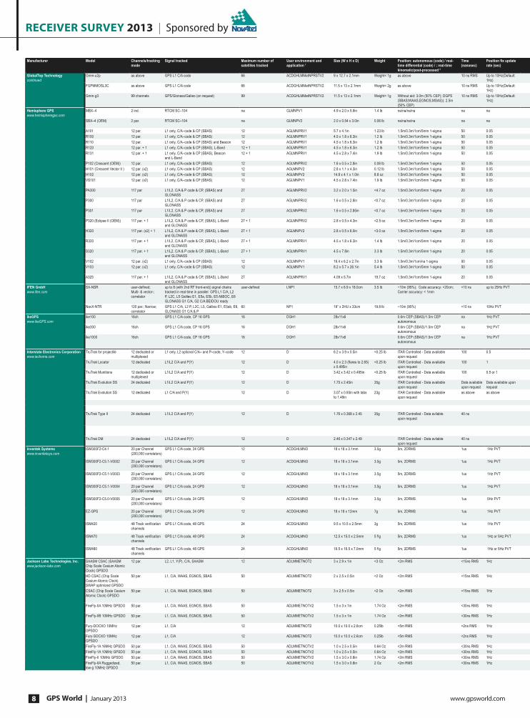
receiver survey 2013 | Sponsored by
GPS World | January 2013 www.gpsworld.com8
Manufacturer Model Channels/tracking
mode
Signal tracked Maximum number of
satellites tracked
User environment and
application 1
Size (W x H x D) Weight Position: autonomous (code) / real-
time differential (code) / ; real-time
kinematic/post-processed 2
Time
(nanosec)
Position Àx update
rate (sec)
GlobalTop Technology
continued
Gmm-u2p as above GPS L1 C/A code 66 ACDGHLMMetNPRSTV2 9 x 12.7 x 2.1mm Weight< 1g as above 10 ns RMS Up to 10Hz(Default:
1Hz)
FGPMMOSL3C as above GPS L1 C/A code 66 ACDGHLMMetNPRSTV2 11.5 x 13 x 2.1mm Weight< 2g as above 10 ns RMS Up to 10Hz(Default:
1Hz)
Gmm-g3 99 channels GPS/Glonass/Galieo (on request) 99 ACDGHLMMetNPRSTV2 11.5 x 13 x 2.1mm Weight< 1g Without aid: 3.0m (50% CEP); DGPS
(SBAS(WAAS,EGNOS,MSAS)): 2.5m
(50% CEP)
10 ns RMS Up to 10Hz(Default:
1Hz)
Hemisphere GPS
www.hemispheregps.com
MBX–4 2 ind. RTCM SC–104 na GLMNPV1 4.9 x 2.0 x 5.9in 1.4 lb na/na/na/na na na
SBX–4 (OEM) 2 par. RTCM SC–104 na GLMNPV2 2.0 x 0.54 x 3.0in 0.06 lb na/na/na/na na na
A101 12 par. L1 only, C/A–code & CP (SBAS) 12 AGLMNPRV1 5.7 x 4.1in 1.23 lb 1.5m/0.3m/1cm/5mm 1-sigma 50 0.05
R100 12 par. L1 only, C/A–code & CP (SBAS) 12 AGLMNPRV1 4.5 x 1.8 x 6.3in 1.2 lb 1.5m/0.3m/1cm/5mm 1-sigma 50 0.05
R110 12 par. L1 only, C/A–code & CP (SBAS) and Beacon 12 AGLMNPRV1 4.5 x 1.8 x 6.3in 1.2 lb 1.5m/0.3m/1cm/5mm 1-sigma 50 0.05
R120 12 par. + 1 L1 only, C/A–code & CP (SBAS), L-Band 12 + 1 AGLMNPRV1 4.5 x 1.8 x 6.3in 1.2 lb 1.5m/0.3m/1cm/5mm 1-sigma 50 0.05
R131 12 par. + 1 L1 only, C/A–code & CP (SBAS), Beacon
and L-Band
12 + 1 AGLMNPRV1 4.5 x 2.8 x 7.4in 1.9 lb 1.5m/0.3m/1cm/5mm 1-sigma 50 0.05
P102 (Crescent (OEM)) 12 par. L1 only, C/A–code & CP (SBAS) 12 AGLMNPRV2 1.6 x 0.5 x 2.8in 0.06 lb 1.5m/0.3m/1cm/5mm 1-sigma 50 0.05
H101 (Crescent Vector II ) 12 par. (x2) L1 only, C/A–code & CP (SBAS) 12 AGLMNPV2 2.8 x 1.1 x 4.3in 0.12 lb 1.5m/0.3m/1cm/5mm 1-sigma 50 0.05
H102 12 par. (x2) L1 only, C/A–code & CP (SBAS) 12 AGLMNPV2 14.8 x 4.1 x 1.0in 8.8 oz 1.5m/0.3m/1cm/5mm 1-sigma 50 0.05
VS101 12 par. (x2) L1 only, C/A–code & CP (SBAS) 12 AGLMNPV1 4.5 x 2.8 x 7.4in 1.9 lb 1.5m/0.3m/1cm/5mm 1-sigma 50 0.05
PA300 117 par L1/L2, C/A & P code & CP, (SBAS) and
GLONASS
27 AGLMNPRV2 3.2 x 2.0 x 1.5in <4.7 oz 1.5m/0.3m/1cm/5mm 1-sigma 20 0.05
P300 117 par L1/L2, C/A & P code & CP, (SBAS) and
GLONASS
27 AGLMNPRV2 1.6 x 0.5 x 2.8in <0.7 oz 1.5m/0.3m/1cm/5mm 1-sigma 20 0.05
P301 117 par L1/L2, C/A & P code & CP, (SBAS) and
GLONASS
27 AGLMNPRV2 1.6 x 0.5 x 2.85in <0.7 oz 1.5m/0.3m/1cm/5mm 1-sigma 20 0.05
P320 (Eclipse II (OEM)) 117 par. + 1 L1/L2, C/A & P code & CP, (SBAS), L-Band
and GLONASS
27 + 1 AGLMNPRV2 2.8 x 0.5 x 4.3in <2.5 oz 1.5m/0.3m/1cm/5mm 1-sigma 20 0.05
H320 117 par. (x2) + 1 L1/L2, C/A & P code & CP, (SBAS), L-Band
and GLONASS
27 + 1 AGLMNPV2 2.8 x 0.5 x 6.0in <3.0 oz 1.5m/0.3m/1cm/5mm 1-sigma 20 0.05
R320 117 par. + 1 L1/L2, C/A & P code & CP, (SBAS), L-Band
and GLONASS
27 + 1 AGLMNPRV1 4.5 x 1.8 x 6.3in 1.4 lb 1.5m/0.3m/1cm/5mm 1-sigma 20 0.05
S320 117 par. + 1 L1/L2, C/A & P code & CP, (SBAS), L-Band
and GLONASS
27 + 1 AGLMNPRV1 4.5 x 7.8in 3.3 lb 1.5m/0.3m/1cm/5mm 1-sigma 20 0.05
V102 12 par. (x2) L1 only, C/A–code & CP (SBAS) 12 AGLMNPV1 16.4 x 6.2 x 2.7in 3.3 lb 1.5m/0.3m/1cm/na 1-sigma 50 0.05
V103 12 par. (x2) L1 only, C/A–code & CP (SBAS) 12 AGLMNPV1 8.2 x 5.7 x 26.1in 5.4 lb 1.5m/0.3m/1cm/5mm 1-sigma 50 0.05
A325 117 par. + 1 L1/L2, C/A & P code & CP, (SBAS), L-Band
and GLONASS
27 AGLMNPRV1 4.09 x 5.7in 19.7 oz 1.5m/0.3m/1cm/5mm 1-sigma 20 0.05
IFEN GmbH
www.ifen.com
SX-NSR user-de¿ned;
Multi- & vector-;
correlator
up to 8 (with 2nd RF front-end)) signal chains
tracked in real-time in parallel GPS L1 C/A, L2
P, L2C, L5 Galileo E1, E5a, E5b, E5 AltBOC, E6
GLONASS G1 C/A, G2 C/A BEIDOU ready
user-de¿ned LNP1 15.7 x 6.9 x 18.0cm 3.5 lb ~10m (95%); Code accuracy: <20cm;
Carrier accuracy: < 1mm
<10 ns up to 25Hz PVT
NavX-NTR 120 par.; Narrow;
correlator
GPS L1 C/A, L2 P, L2C, L5, Galileo E1, E5ab, E6,
GLONASS G1 C/A & P
60 NP1 19” x 2HU x 33cm 19.8 lb ~10m (95%) <10 ns 10Hz PVT
ikeGPS
www.ikeGPS.com
ike100 16ch GPS L1 C/A code, CP 16 GPS 16 DGH1 28x11x6 0.6m CEP (SBAS)/1.5m CEP
autonomous
na 1Hz PVT
ike300 16ch GPS L1 C/A code, CP 16 GPS 16 DGH1 28x11x6 0.6m CEP (SBAS)/1.5m CEP
autonomous
na 1Hz PVT
ike1000 16ch GPS L1 C/A code, CP 16 GPS 16 DGH1 28x11x6 0.6m CEP (SBAS)/1.5m CEP
autonomous
na 1Hz PVT
Interstate Electronics Corporation
www.iechome.com
TruTrak for projectile 12 dedicated or
multiplexed
L1 only, L2 optional C/A– and P–code, Y–code 12 D 6.2 x 3.9 x 0.5in <0.25 lb ITAR Controlled - Data available
upon request
100 0.5
TruTrak Locator 12 dedicated L1/L2 C/A and P(Y) 12 D 4.0 x 2.3 (Àares to 2.65)
x 0.495in
<0.25 lb ITAR Controlled - Data available
upon request
100 1
TruTrak Munitions 12 dedicated or
multiplexed
L1/L2 C/A and P(Y) 12 D 3.42 x 3.42 x 0.495in <0.25 lb ITAR Controlled - Data available
upon request
100 0.5 or 1
TruTrak Evolution DS 24 dedicated L1/L2 C/A and P(Y) 12 D 1.75 x 2.45in 35g ITAR Controlled - Data available
upon request
Data available
upon request
Data available upon
request
TruTrak Evolution SS 12 dedicated L1 C/A and P(Y) 12 D 3.07 x 0.93in with tabs
to 1.49in
23g ITAR Controlled - Data available
upon request
as above as above
TruTrak Type II 24 dedicated L1/L2 C/A and P(Y) 12 D 1.76 x 0.368 x 2.45 35g ITAR Controlled - Data avliable
upon request
40 ns
TruTrak DM 24 dedicated L1/L2 C/A and P(Y) 12 D 2.46 x 0.347 x 2.49 ITAR Controlled - Data avliable
upon request
40 ns
Inventek Systems
www.inventeksys.com
ISM300F2-C4.1 20 par Channel
(200,000 correlators)
GPS L1 C/A code, 24 GPS 12 ACDGHLMNO 18 x 18 x 3.1mm 3.5g 5m, 2DRMS 1us 1Hz PVT
ISM300F2-C5.1-V0002 20 par Channel
(200,000 correlators)
GPS L1 C/A code, 24 GPS 12 ACDGHLMNO 18 x 18 x 3.1mm 3.5g 5m, 2DRMS 1us 1Hz PVT
ISM300F2-C5.1-V0003 20 par Channel
(200,000 correlators)
GPS L1 C/A code, 24 GPS 12 ACDGHLMNO 18 x 18 x 3.1mm 3.5g 5m, 2DRMS 1us 1Hz PVT
ISM300F2-C5.1-V0004 20 par Channel
(200,000 correlators)
GPS L1 C/A code, 24 GPS 12 ACDGHLMNO 18 x 18 x 3.1mm 3.5g 5m, 2DRMS 1us 1Hz PVT
ISM300F2-C5.0-V0005 20 par Channel
(200,000 correlators)
GPS L1 C/A code, 24 GPS 12 ACDGHLMNO 18 x 18 x 3.1mm 3.5g 5m, 2DRMS 1us 5Hz PVT
EZ-GPS 20 par Channel
(200,000 correlators)
GPS L1 C/A code, 24 GPS 12 ACDGHLMNO 18 x 18 x 12mm 7g 5m, 2DRMS 1us 1Hz PVT
ISM420 48 Track veri¿cation
channels
GPS L1 C/A code, 48 GPS 24 ACDGHLMNO 9.5 x 10.5 x 2.5mm 3g 5m, 2DRMS 1us 1Hz PVT
ISM470 48 Track veri¿cation
channels
GPS L1 C/A code, 48 GPS 24 ACDGHLMNO 12.5 x 15.0 x 2.5mm 5 f\g 5m, 2DRMS 1us 1Hz or 5Hz PVT
ISM480 48 Track veri¿cation
channels
GPS L1 C/A code, 48 GPS 24 ACDGHLMNO 16.5 x 16.5 x 7.0mm 5 f\g 5m, 2DRMS 1us 1Hz or 5Hz PVT
Jackson Labs Technologies, Inc.
www.jackson-labs.com
SAASM CSAC (SAASM
Chip Scale Cesium Atomic
Clock) GPSDO
12 par. L2, L1, Y(P), C/A, SAASM 12 ADLMMETNOT2 3 x 2.9 x 1in <3 Oz <2m RMS <15ns RMS 1Hz
HD CSAC (Chip Scale
Cesium Atomic Clock)
SWAP optimized GPSDO
50 par. L1, C/A, WAAS, EGNOS, SBAS 50 ADLMMETNOT2 2 x 2.5 x 0.5in <2 Oz <2m RMS <15ns RMS 1Hz
CSAC (Chip Scale Cesium
Atomic Clock) GPSDO
50 par. L1, C/A, WAAS, EGNOS, SBAS 50 ADLMMETNOT2 3 x 2.5 x 0.5in <2 Oz <2m RMS <15ns RMS 1Hz
FireFly-IIA 10MHz GPSDO 50 par. L1, C/A, WAAS, EGNOS, SBAS 50 ADLMMETNOTV2 1.5 x 3 x 1in 1.74 Oz <2m RMS <30ns RMS 1Hz
FireFly-IIB 10MHz GPSDO 50 par. L1, C/A, WAAS, EGNOS, SBAS 50 ADLMMETNOTV2 1.5 x 3 x 1in 1.74 Oz <2m RMS <30ns RMS 1Hz
Fury-DOCXO 10MHz
GPSDO
12 par. L1, C/A 12 ADLMMETNOT2 10.0 x 10.0 x 2.6cm 0.25lb <5m RMS <2ns RMS 1Hz
Fury-SOCXO 10MHz
GPSDO
12 par. L1, C/A 12 ADLMMETNOT2 10.0 x 10.0 x 2.6cm 0.25lb <5m RMS <2ns RMS 1Hz
FireFly-1A 16MHz GPSDO 50 par. L1, C/A, WAAS, EGNOS, SBAS 50 ADLMMETNOTV2 1.0 x 2.5 x 0.5in 0.64 Oz <2m RMS <30ns RMS 1Hz
FireFly-1A 10MHz GPSDO 50 par. L1, C/A, WAAS, EGNOS, SBAS 50 ADLMMETNOTV2 1.0 x 2.5 x 0.5in 0.64 Oz <2m RMS <30ns RMS 1Hz
FireFly-II 10MHz GPSDO 50 par. L1, C/A, WAAS, EGNOS, SBAS 50 ADLMMETNOTV2 1.5 x 3.0 x 0.8in 1.74 Oz <2m RMS <30ns RMS 1Hz
FireFly-IIA Ruggedized,
low-g 10MHz GPSDO
50 par. L1, C/A, WAAS, EGNOS, SBAS 50 ADLMMETNOTV2 1.5 x 3.0 x 0.8in 2 Oz <2m RMS <30ns RMS 1Hz

Sponsored by | receiver survey 2013
www.gpsworld.com January 2013 | GPS World 9
Cold start 3 Warm start 4 Reacquisition 5 No. of ports Port type Baud rate Operating temperature
(degrees Celsius)
Power source Power consumption
(Watts)
Antenna type 6 Description or Comments
<<35s <33s <1s 2 UART as above –40 to +85 ext 50 mW ext MTK (MediaTek) 3339 chipset, low power consumption,
advanced software supported
<<35s <33s <1s 2 UART 4,800–9,600 –30 to +70 ext 50 mW ext MTK (MediaTek) 3339 chipset, additional ext antenna
supported
<<35s <33s <1s 2 UART 4,800–115,200 –30 to +70 ext 96 mW ext MTK (MediaTek) 3333 chipset, additional ext antenna
supported
<60s <2s 2s 1 RS-232 or RS-422 4,800–115,200 –40 to +70 External 2.5 Beacon (ER) (included) 61108-4 compliant beacon receiver
<60s 30s <10s 2 3.3 V HCMOS 4,800–115,200 –30 to +70 External <0.25 Beacon (ER) 61108-4 compliant beacon board with database search
receiver module
60s 30s <10s 2 RS-232, CAN 4,800–115,200 –30 to +70 External <3 Integrated GPS+SBAS GPS and SBAS smart antenna
60s 30s <10s 3 RS-232, USB 4,800–115,200 –30 to +70 External <3 GPS + SBAS + LBand (ER) (inc.) GPS and SBAS receiver
60s 30s <10s 3 RS-232, USB 4,800–115,200 –30 to +70 External <3 GPS + SBAS + LBand (ER) (inc.) GPS, Beacon and SBAS receiver
60s 30s <10s 3 RS-232, USB 4,800–115,200 –30 to +70 External <3 GPS + Beacon + SBAS (ER) (inc.) GPS, OmniSTAR and SBAS receiver
60s 30s <10s 3 RS-232, USB 4,800–115,200 –30 to +70 External <3 GPS + SBAS + LBand (ER) (inc.) GPS, OmniSTAR, Beacon and SBAS receiver
60s 30s <10s 4 3.3 V HCMOS 4,800–115,200 –30 to +70 External <1.0 GPS + SBAS (ER) GPS and SBAS receiver module
60s 30s <10s 4 3.3 V HCMOS 4,800–115,200 –30 to +70 External <1 GPS + SBAS (ER) GPS and SBAS compass receiver module
60s 30s <10s 2 RS-232 4,800–115,200 –40 to +70 External <3 GPS + SBAS (ER) GPS and SBAS compass receiver module
60s 30s <10s 2 RS-232 4,800–115,200 –30 to +70 External <5 GPS + SBAS (ER) (included) GPS and SBAS compass computes heading < 0.1° accuracy
(optional beacon differential)
60s 30s <10s 2 3.3 V HCMOS 4,800–115,200 –30 to +70 External <1.9 GPS + SBAS + GLONASS (ER) L1/L2 GPS & GLONASS and SBAS receiver module
60s 30s <10s 4 3.3 V HCMOS, USB 4,800–115,200 –40 to +85 External <1.9 GPS + SBAS + GLONASS (ER) L1/L2 GPS & GLONASS and SBAS receiver module
60s 30s <10s 4 3.3 V HCMOS, USB 4,800–115,200 –30 to +70 External <1.9 GPS + SBAS + GLONASS (ER) L1/L2 GPS & GLONASS and SBAS receiver module
60s 30s <10s 5 3.3 V HCMOS, USB 4,800–115,200 –40 to +70 External <2.5 GPS + SBAS + Lband +
GLONASS (ER)
L1/L2 GPS & GLONASS, OmniSTAR VBS/HP/XP/G2, and
SBAS receiver module
60s 30s <10s 5 3.3 V HCMOS, USB 4,800–115,200 –30 to +70 External <3.25 GPS + SBAS + Lband +
GLONASS (ER)
L1/L2 GPS & GLONASS, OmniSTAR VBS/HP/XP/G2
compass receiver module
60s 30s <10s 4 RS-232, USB 4,800–115,200 –30 to +70 External <4.3 GPS + SBAS + Lband + GLONASS
(ER) (inc.)
L1/L2 GPS & GLONASS, OmniSTAR VBS/HP/XP/G2, and
SBAS receiver
60s 30s <10s 6 RS-232 (Multi-Use), RS-232, Bluetooth,
USB, Bluetooth, SD
4,800–38,400 –30 to +70 Internal w/ Option
of External
Rover: 4.4 Base Tx
UHF: 7
Integrated GPS + SBAS + Lband +
GLONASS (ER)
L1/L2 GPS & GLONASS, OmniSTAR VBS/HP/XP/G2, and
SBAS Samrt Antenna
60s 30s <10s 2 RS-232 4,800–115,200 -40 to +70 External <3 GPS + SBAS GPS and SBAS compass receiver
60s 30s <10s 2 RS-232 480 Mbps USB 0 to +50 External <5 Integrated GPS + SBAS GPS ans SBAS compass receiver with integrated antennas
(optional beacon differential)
60s 30s <10s 2 RS-232, Bluetooth, CAN 10/100 Mbps -10 to +60 External <4.6 GPS + SBAS + Lband + GLONASS
(ER) (inc.)
L1/L2 GPS & GLONASS, OmniSTAR VBS/HP/XP/G2, and
SBAS receiver module
<55s <10s <1s 1 (2) 1 USB 2.0; (2 USB 2.0 with 2nd RF
front-end)
-10 to +50 external <7.5W (<15W with 2nd
RF front-end)
Active, external Multi-frequency real-time software receiver with heading
(dual antenna) feature and external sensor data interface;;
includes an external notebook
<60s <30s <1s 1 1 Ethernet -10 to +50 ext (AC/DC) 90W Active, external Monitoring and reference station apps
<35s <20s <5s 1 USB, RS232 -10 to +50 int na Internal Patch internal Laser range¿nder (100m), compass and camera. For
measuring remote positions and dimensions from images
<35s <20s <5s 1 USB, RS232 153.6k (nominal) –42 to +85 int na Internal Patch internal Laser range¿nder (300m), compass and camera. For
measuring remote positions and dimensions from images
<35s <20s <5s 1 USB, RS232 9,600 (nominal) –20 to +70 int na Internal Patch internal Laser range¿nder (1000m), compass and
camera. For measuring remote positions and dimensions
from images
120s 35s 5s 2 RS-422, TTL 153.6k (nominal) –40 to +85 ext 3 (typ) E
120s 35s 5s 2 Serial RS-232 Serial TTL - CDU (debug) Data available upon
request
Data available upon
request
ext 3 (typ) E
120s 35s 5s 2 Serial RS-422 Serial TTL - CDU (debug) as above as above ext 3 (typ) E
Data available
upon request
Data available
upon request
Data available upon
request
3 COM1 ( either RS-232 or CMOS), COM2
(CMOS), DS-101/102, TOD and 1PPS
Input power
3.3 VDC
Data available upon
request
Two active Fully security approved con¿guration
as above as above as above 3 1 x RS 232 and 2 x CMOS serial ports,
DS-101,TOD and 1-10PPS
as above as above Passive as above
- 40 to +85
<120s <60 Data Avaliable on
request
8 serial data ports, 2RS - 232 2 SPI ( 7
slaves) 2 SDLC AMRAAM IMU Ports 21
general purpose I/O Extrenal 10MHz input
- 40 to +85 3.3 1.5 Passive and Active
4800 NMEA and 57,600
SiRF Binary
–40to +85
Data avliable on
request
Data avliable on request 5 x RS - 422 supports SDLC/AMRAAM
DS101/102 TOD & 1PPS
4800 NMEA and 57,600
SiRF Binary
–40to +85 3.3 2 Passive
<<35 <<35 100ms 2 UARTS up to 115200 Kbps 4800 NMEA and 57,600
SiRF Binary
–40to +85 3.0-5V dc 100 mW acquisition, 65
mW tracking
Active direct connect via U.FL or
Pin 1 trace
Standard Firmware with -159 dBm tracking mode.
<<35s <<35s 100ms 1 UART NMEA 57600 SBAS enabled 4800 NMEA and 57,600
SiRF Binary
–40to +85 3.0-5V dc 25 mA tracking Active direct connect via U.FL or
Pin 1 trace
Standard Firmware with -159 dBm tracking mode.
<<35s <<35s 100ms 2 NMEA 4800, Sirf Binary 57600 MID41 only 4800 NMEA and 57,600
SiRF Binary
–40to +85 3.0-5V dc 25 mA tracking Active direct connect via U.FL or
Pin 1 trace
MID41 only
<<35s <<35s 100ms 2 Sirf Binary 57600, NMEA 4800, High
Altitude Build 42000 meters
4800 NMEA and 57,600
SiRF Binary
–40to +85 3.0-5V dc 25 mA tracking Active direct connect via U.FL or
Pin 1 trace
High Altitude for Balloons
<<35s <<35s 100ms 2 Sirf Binary 115200, NMEA 57600,
5Hz outpu
4800 NMEA, 57,600
OSP, ROM
–35 to +85 3.0-5V dc 25 mA tracking Active direct connect via U.FL or
Pin 1 trace
True 5Hz output
<<35s <<35s 100ms 1 UART NMEA 4800 4800 NMEA, 57,600
OSP - Prog.
–35 to +85 3.0-5V dc 25 mA tracking SMA tp actoive antennna USB dongle with external GPS
<<35s <<8s 100ms 1 SPI,UART,I2C 4800 NMEA, 5,7600
OSP - Prog.
–35 to +85 1.8 V dc 10 mW trickle mode Ext. passive antenna, surface
mount device
Integrated LNA, Low Cost ROM based.
<<35s <<8s 100ms 1 SPI,UART,I2C 9,600 - 115,200 -45 to +85’ 1.8 V dc 10 mW trickle mode Ext. passive antenna, surface
mount device
Integrated LNA, Flashed based,SGEE and CGEE capability
<<35s <<8s 100ms 1 SPI,UART,I2C 9,600 - 115,200 -45 to +85’ 1.8 V dc 10 mW trickle mode Integrated ceramic Antenna 12 pin connector, fully integrated stand alone GPS with anti
jamming, SGEE and CGEE
<45s <1s <1s 2 DS101 Key-Port, RS-232, USB, Alarm,
10MHz, 5MHz, 1PPS, LCD port
9,600 - 115,200 -45 to +85’ 8.0-36.0 V <2.7W 5V SAASM GPS with Y(P) code (Keyed), C/A code, and Chip
Scale Cesium Atomic Clock, two NMEA and SCPI ports
<45s <1s <1s 2 RS-232, Alarm, 10MHz, 1PPS 9,600 - 115,200 -20 to +85’ 11.0-14.0 V <1.2W 5V Chip Scale Cesium Atomic Clock with GPS Disciplining, low
Size Weight And Power optimized
<45s <1s <1s 2 RS-232, USB, Alarm, 10MHz, 5MHz,
1PPS, LCD port
9,600 - 115,200 -20 to +85’ 8.0-36.0 V <1.4W 5V Chip Scale Cesium Atomic Clock with GPS Disciplining,
two NMEA and SCPI ports, and Distribution Ampli¿er with
5 isolated outputs
<45s <1s <1s 1 RS-232, Alarm, 10MHz, 1PPS 9,600 - 115,200 -20 to +85’ 11.0-14.0 V <3.5W 5V Built-In 10MHz Distribution Ampli¿er, 3-Axis Accelerometer,
low-g option
<45s <1s <1s 1 RS-232, Alarm, 10MHz, 1PPS 9,600 - 115,200 -20 to +85’ 11.0-14.0 V <3.5W 5V Built-In 4-channel 10MHz Distribution Ampli¿er, low
vibration sensitivity
<150s <40s <1s 1 RS-232, Alarm, 10MHz, 1PPS 9,600 - 115,200 -20 to +85’ 11.0-14.0 V <4.5W 3.3V or 5V Rubidium Oscillator Replacement
<150s <40s <1s 1 RS-232, Alarm, 10MHz, 1PPS 9,600 - 115,200 -20 to +85’ 11.0-14.0 V <4.5W 3.3V or 5V Better than 1E-012 stability
<45s <1s <1s 1 RS-232, Alarm, 16MHz, 1PPS 9,600 - 115,200 -20 to +85’ 8.0-14.0 V <1.4W 3.3V Ultra small and light, 16MHz output
<45s <1s <1s 1 RS-232, Alarm, 10MHz, 1PPS 9,600 - 115,200 -20 to +85’ 8.0-14.0 V <1.4W 3.3V Ultra small and light GPS Disciplined Oscillator
<45s <1s <1s 1 RS-232, Alarm, 10MHz, 1PPS 9,600 - 115,200 -20 to +85’ 11.0-14.0 V <3.5W 3.3V 3D velocity, stability: <1E-011
<45s <1s <1s 1 RS-232, Alarm, 10MHz, 1PPS 9,600 - 115,200 -20 to +85’ 11.0-14.0 V <3.5W 3.3V Mil rugged, stability <1E-011, <3E-010 per-g sensitivity

receiver survey 2013 | Sponsored by
GPS World | January 2013 www.gpsworld.com10
Manufacturer Model Channels/tracking
mode
Signal tracked Maximum number of
satellites tracked
User environment and
application 1
Size (W x H x D) Weight Position: autonomous (code) / real-
time differential (code) / ; real-time
kinematic/post-processed 2
Time
(nanosec)
Position Àx update
rate (sec)
Jackson Labs Technologies, Inc.
continued
ULN-2550
25MHz/100MHz/10MHz
GPSDO
50 par. L1, C/A, WAAS, EGNOS, SBAS 50 ADLMMETNOTV2 1.5 x 3.5 x 0.8in 1.8 Oz <2m RMS <30ns RMS 1Hz
ULN-1100 100MHz GPSDO 50 par. L1, C/A, WAAS, EGNOS, SBAS 50 ADLMMETNOTV2 1.5 x 4 x 1in 1.8 Oz <2m RMS <30ns RMS 1Hz
EuroCan GPSOCXO
10MHz/16MHz
50 par. L1, C/A, WAAS, EGNOS, SBAS 50 ADLMMETNOTV2 1.07 x 1.42 x 0.5in 0.8 Oz <2m RMS <30ns RMS 1Hz
EuroCan GPSTCXO
10MHz/16MHz
50 par. L1, C/A, WAAS, EGNOS, SBAS 50 ADLMMETNOTV2 1.07 x 1.42 x 0.5in 0.8 Oz <2m RMS <30ns RMS 1Hz
USB GPSTCXO 10MHz 50 par. L1, C/A, WAAS, EGNOS, SBAS 50 ADLMMETNOTV2 3 x 2 x 0.5in 2 Oz <2m RMS <30ns RMS 1Hz
Mini-JLT GPSDO 50 par. L1, C/A, WAAS, EGNOS, SBAS 50 ADLMMETNOTV2 5.05 x 1.38 x 0.7in 2 Oz <2m RMS <15ns RMS 1Hz
LC_XO GPSDO 10MHz 50 par. L1, C/A, WAAS, EGNOS, SBAS 50 ADLMMETNOTV2 0.97x0.97x0.5 <1 Oz <2m RMS <30ns RMS 1Hz
Japan Radio Co., Ltd.
www.jrc.co.jp/eng/
GPS9 Series: CCA-700 16 channels +
search channel
GPS/Galileo/SBAS/Quasi-zenith 16 CHLMNPV2 12.4mm(D) x 12.4mm(W)
x 2.5mm(H)
0.7g (approx) 2.3m typ;./2.0m typ;./na; (CEP) na 1Hz
JAVAD GNSS
www.javad.com
TRIUMPH-1 216 GPS CA/P1/P2/L2C/L5; Galileo E1/E5A/E5B;
GLONASS CA/P1/P2/L2C/L3; SBAS L1/L5;
QZSS CA/SAIF/L2C/L5/L1C; Compass E1/E5B
all in view 1AGLMTNPROMet 178 x 96 x 178mm 1700 g <2m/<0.5m /1cm+1 ppm/; 0.3cm+0.5
ppm
3 100Hz
TRIUMPH-VS 216 GPS CA/P1/P2/L2C/L5; Galileo E1/E5A/E5B;
GLONASS CA/P1/P2/L2C/L3; SBAS L1/L5;
QZSS CA/SAIF/L2C/L5/L1C; Compass E1/E5B
all in view 1GHLMTNPROMet 178 x 109 x 110mm 1700 g <2m/<0.5m /1cm+1 ppm/; ; 0.3cm+0.5
ppm
3 100Hz
TRIUMPH-NT 216 GPS CA/P1/P2/L2C/L5; Galileo E1/E5A/E5B;
GLONASS CA/P1/P2/L2C/L3; SBAS L1/L5;
QZSS CA/SAIF/L2C/L5/L1C; Compass E1/E5B
all in view 1GHLMTNPROMet 178 x 100 x 110mm 1700 g <2m/<0.5m /1cm+1 ppm/; 0.3cm+0.5
ppm
3 100Hz
TRUIMPH-4X 216 4x GPS CA/P1/P2/L2C/L5; 4x Galileo E1/E5A;
4x SBAS L1/L5; 4x QZSS CA/SAIF/L2C/L5/L1C;
4x Compass E1
all in view 1AGLMTNPROMet 178 x 93 x 178mm 1850 g <2m/<0.5m /0.6cm+1 ppm/;
0.3cm+0.5 ppm
3 20Hz
Alpha G3 216 GPS CA; Galileo E1; GLONASS CA; SBAS L1;
QZSS CA/SAIF/L1C; Compass E1
all in view 1AGLMTNPROMet 148 x 85 x 35mm 430 g <2m/<0.5m /1.5cm+2 ppm/;
0.5cm+1.5ppm
3 100Hz
Alpha G2T 216 GPS CA/P1/P2/L2C/L5; Galileo E1/E5A; SBAS
L1/L5; QZSS CA/SAIF/L2C/L5/L1C; Compass E1
all in view 1AGLMTNPROMet 148 x 85 x 35mm 435 g <2m/<0.5m /1cm+1 ppm/; 0.3cm+0.5ppm 3 100Hz
Alpha G3T 216 GPS CA/P1/P2/L2C/L5; Galileo E1/E5A;
GLONASS CA/P1/P2/L2C; SBAS L1/L5; QZSS
CA/SAIF/L2C/L5/L1C; Compass E1
all in view 1AGLMTNPROMet 148 x 85 x 35mm 448 g <2m/<0.5m /1cm+1 ppm/; 0.3cm+0.5
ppm
3 100Hz
Alpha2-G3 216 GPS CA; Galileo E1; GLONASS CA; SBAS L1;
QZSS CA/SAIF/L1C; Compass E1
all in view 1AGLMTNPROMet 148 x 85 x 35mm 430 g <2m/<0.5m /1.5cm+2 ppm/;
0.5cm+1.5 ppm
3 100Hz
Alpha2-G2 216 GPS CA; Galileo E1; SBAS L1; QZSS CA/SAIF/
L1C; Compass E1
all in view 1AGLMTNPROMet 148 x 85 x 35mm 415 g <2m/<0.5m /1.5cm+2 ppm/;
0.5cm+1.5 ppm
3 100Hz
Alpha2-G2T 216 GPS CA/P1/P2/L2C/L5; Galileo E1/E5A; SBAS
L1/L5; QZSS CA/SAIF/L2C/L5/L1C; Compass E1
all in view 1AGLMTNPROMet 148 x 85 x 35mm 435 g <2m/<0.5m /1cm+1 ppm/; 0.3cm+0.5
ppm
3 100Hz
Alpha2-G3T 216 GPS CA/P1/P2/L2C/L5; Galileo E1/E5A;
GLONASS CA/P1/P2/L2C; SBAS L1/L5; QZSS
CA/SAIF/L2C/L5/L1C; Compass E1
all in view 1AGLMTNPROMet 148 x 85 x 35mm 448 g <2m/<0.5m /1cm+1 ppm/; 0.3cm+0.5
ppm
3 100Hz
Delta G2T 216 GPS CA/P1/P2/L2C/L5; Galileo E1/E5A; SBAS
L1/L5; QZSS CA/SAIF/L2C/L5/L1C; Compass E1
all in view 1AGLMTNPROMet 109 x 35 x 169mm 394 g <2m/<0.5m /1cm+1 ppm/; 0.3cm+0.5
ppm
3 100Hz
Delta G3T 216 GPS CA/P1/P2/L2C/L5; Galileo E1/E5A/E5B;
GLONASS CA/P1/P2/L2C/L3; SBAS L1/L5;
QZSS CA/SAIF/L2C/L5/L1C; Compass E1/E5B
all in view 1AGLMTNPROMet 109 x 35 x 169mm 401 g <2m/<0.5m /1cm+1 ppm/; 0.3cm+0.5
ppm
3 100Hz
Delta-G3TAJ 216 GPS CA/P1/P2/L2C/L5; Galileo E1/E5A/E5B;
GLONASS CA/P1/P2/L2C/L3; SBAS L1/L5;
QZSS CA/SAIF/L2C/L5/L1C; Compass E1/E5B
all in view 1AGLMTNPROMet 109 x 35 x 169mm 401 g <2m/<0.5m /1cm+1 ppm/; 0.3cm+0.5
ppm
3 100Hz
Delta D-G2 216 2x GPS CA; 2x Galileo E1; 2x SBAS L1; 2x QZSS
CA/SAIF/L1C; 2x Compass E1
all in view 1AGLMTNPROMet 109 x 35 x 169mm 414 g <2m/<0.5m /1.5cm+2 ppm/;
0.5cm+1.5 ppm
3 100Hz
Delta D-G2D 216 2x GPS CA/P1/P2/L2C; 2x Galileo E1; 2x SBAS
L1; 2x QZSS CA/SAIF/L2C/L1C; 2x Compass E1
all in view 1AGLMTNPROMet 109 x 35 x 169mm 414 g <2m/<0.5m /1cm+1 ppm/; 0.3cm+0.5
ppm
3 100Hz
Delta D-G3D 216 2x GPS CA/P1/P2/L2C; 2x Galileo E1; 2x
Glonass CA/P1/P2/L2C; 2x SBAS L1; 2x QZSS
CA/SAIF/L2C/L1C; 2x Compass E1
all in view 1AGLMTNPROMet 109 x 35 x 169mm 414 g <2m/<0.5m /1cm+1 ppm/; 0.3cm+0.5
ppm
3 100Hz
Delta Q-G3D 216 4x GPS CA/P1/P2/L2C; 4x Galileo E1; 1x
Glonass CA/P1/P2/L2C; 4x SBAS L1; 4x QZSS
CA/SAIF/L2C/L1C; 4x Compass E1
all in view 1AGLMTNPROMet 109 x 35 x 169mm 454 g <2m/<0.5m /1cm+1 ppm/; 0.3cm+0.5
ppm
3 100Hz
Sigma G2T 216 GPS CA/P1/P2/L2C/L5; Galileo E1/E5A; SBAS
L1/L5; QZSS CA/SAIF/L2C/L5/L1C; Compass E1
all in view 1AGLMTNPROMet 132 x 61 x 190mm 1270 g <2m/<0.5m /1cm+1 ppm/; 0.3cm+0.5
ppm
3 100Hz
Sigma G3T 216 GPS CA/P1/P2/L2C/L5; Galileo E1/E5A/E5B;
GLONASS CA/P1/P2/L2C/L3; SBAS L1/L5;
QZSS CA/SAIF/L2C/L5/L1C; Compass E1/E5B
all in view 1AGLMTNPROMet 132 x 61 x 190mm 1277 g <2m/<0.5m /1cm+1 ppm/; 0.3cm+0.5
ppm
3 100Hz
Sigma G3TAJ 216 GPS CA/P1/P2/L2C/L5; Galileo E1/E5A/E5B;
GLONASS CA/P1/P2/L2C/L3; SBAS L1/L5;
QZSS CA/SAIF/L2C/L5/L1C; Compass E1/E5B
all in view 1AGLMTNPROMet 132 x 61 x 190mm 1270 g <2m/<0.5m /1cm+1 ppm/; 0.3cm+0.5
ppm
3 100Hz
Sigma D-G2 216 2x GPS CA; 2x Galileo E1; 2x SBAS L1; 2x QZSS
CA/SAIF/L1C; 2x Compass E1
all in view 1AGLMTNPROMet 132 x 61 x 190mm 1290 g <2m/<0.5m /1.5cm+2 ppm/;
0.5cm+1.5 ppm
3 100Hz
Sigma D-G2D 216 2x GPS CA/P1/P2/L2C; 2x Galileo E1; 2x SBAS
L1; 2x QZSS CA/SAIF/L2C/L1C; 2x Compass E1
all in view 1AGLMTNPROMet 132 x 61 x 190mm 1290 g <2m/<0.5m /1cm+1 ppm/; 0.3cm+0.5
ppm
3 100Hz
Sigma D-G3D 216 2x GPS CA/P1/P2/L2C; 2x Galileo E1; 2x
Glonass CA/P1/P2/L2C; 2x SBAS L1; 2x QZSS
CA/SAIF/L2C/L1C; 2x Compass E1
all in view 1AGLMTNPROMet 132 x 61 x 190mm 1290 g <2m/<0.5m /1cm+1 ppm/; 0.3cm+0.5
ppm
3 100Hz
Sigma Q-G3D 216 4x GPS CA/P1/P2/L2C; 4x Galileo E1; 1x
Glonass CA/P1/P2/L2C; 4x SBAS L1; 4x QZSS
CA/SAIF/L2C/L1C; 4x Compass E1
all in view 1AGLMTNPROMet 132 x 61 x 190mm 1330 g <2m/<0.5m /1cm+1 ppm/; 0.3cm+0.5
ppm
3 100Hz
GISmore 216 GPS CA; Galileo E1; GLONASS CA; SBAS L1;
QZSS CA/SAIF/L1C; Compass E1
all in view 1GORPV 79 x 36 x 131mm 303 g <3m/<0.5m /1.5cm+2 ppm/;
0.7cm+1.5 ppm
3 100Hz
TR-G2 216 GPS CA; Galileo E1; SBAS L1; QZSS CA/SAIF/
L1C; Compass E1
all in view 2AGLMTNPROMet 55 x 40 x 13mm 21 g <2m/<0.5m /1.5cm+2 ppm/;
0.5cm+1.5 ppm
3 100Hz
TR-G3 216 GPS CA; Galileo E1; GLONASS CA; SBAS L1;
QZSS CA/SAIF/L1C; Compass E1
all in view 2AGLMTNPROMet 57 x 66 x 12mm 34 g <2m/<0.5m /1.5cm+2 ppm/;
0.5cm+1.5 ppm
3 100Hz
TR-G2T 216 GPS CA/P1/P2/L2C/L5; Galileo E1/E5A; SBAS
L1/L5; QZSS CA/SAIF/L2C/L5/L1C; Compass E1
all in view 2AGLMTNPROMet 57 x 66 x 12mm 34 g <2m/<0.5m /1cm+1 ppm/; 0.3cm+0.5
ppm
3 100Hz
TR-G3T 216 GPS CA/P1/P2/L2C/L5; Galileo E1/E5A;
GLONASS CA/P1/P2/L2C; SBAS L1/L5; QZSS
CA/SAIF/L2C/L5/L1C; Compass E1
all in view 2AGLMTNPROMet 57 x 88 x 12mm 47 g <2m/<0.5m /1cm+1 ppm/; 0.3cm+0.5
ppm
3 100Hz
TRE-G2T 216 GPS CA/P1/P2/L2C/L5; Galileo E1/E5A; SBAS
L1/L5; QZSS CA/SAIF/L2C/L5/L1C; Compass E1
all in view 2AGLMTNPROMet 100 x 80 x 14mm 70 g <2m/<0.5m /1cm+1 ppm/; 0.3cm+0.5
ppm
3 100Hz
TRE-G3T 216 GPS CA/P1/P2/L2C/L5; Galileo E1/E5A/E5B;
GLONASS CA/P1/P2/L2C/L3; SBAS L1/L5;
QZSS CA/SAIF/L2C/L5/L1C; Compass E1/E5B
all in view 2AGLMTNPROMet 100 x 80 x 14mm 77 g <2m/<0.5m /1cm+1 ppm/; 0.3cm+0.5
ppm
3 100Hz
TRE-G3TAJ 216 GPS CA/P1/P2/L2C/L5; Galileo E1/E5A/E5B;
GLONASS CA/P1/P2/L2C/L3; SBAS L1/L5;
QZSS CA/SAIF/L2C/L5/L1C; Compass E1/E5B
all in view 2AGLMTNPROMet 100 x 80 x 14mm 77 g <2m/<0.5m /1cm+1 ppm/; 0.3cm+0.5
ppm
3 100Hz
Duo-G2 216 2x GPS CA; 2x Galileo E1; 2x SBAS L1; 2x QZSS
CA/SAIF/L1C; 2x Compass E1
all in view 2AGLMTNPROMet 100 x 80 x 14mm 90 g <2m/<0.5m /1.5cm+2 ppm/;
0.5cm+1.5 ppm
3 100Hz
Duo-G2D 216 2x GPS CA/P1/P2/L2C; 2x Galileo E1; 2x SBAS
L1; 2x QZSS CA/SAIF/L2C/L1C; 2x Compass E1
all in view 2AGLMTNPROMet 100 x 80 x 14mm 90 g <2m/<0.5m /1cm+1 ppm/; 0.3cm+0.5
ppm
3 100Hz
Duo-G3D 216 2x GPS CA/P1/P2/L2C; 2x Galileo E1; 2x
Glonass CA/P1/P2/L2C; 2x SBAS L1; 2x QZSS
CA/SAIF/L2C/L1C; 2x Compass E1
all in view 2AGLMTNPROMet 100 x 80 x 14mm 90 g <2m/<0.5m /1cm+1 ppm/; 0.3cm+0.5
ppm
3 100Hz
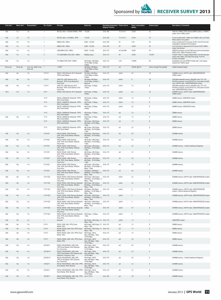
Sponsored by | receiver survey 2013
www.gpsworld.com January 2013 | GPS World 11
Cold start 3 Warm start 4 Reacquisition 5 No. of ports Port type Baud rate Operating temperature
(degrees Celsius)
Power source Power consumption
(Watts)
Antenna type 6 Description or Comments
<45s <1s <1s 1 RS-232, Alarm, 10/25/50/100MHz, 1PPS 115,200 -20 to +85’ 11.0-14.0 V <3.5W 5V Adds four 25MHz LVDS outputs (50MHz option), a 100MHz
output, and a 10MHz output
<45s <1s <1s 1 RS-232, Alarm, 10/100MHz, 1PPS 115,200 -20 to +85’ 11.0-14.0 V <3.5W 5V 3-Axis Accelerometer, 10MHz and 100MHz Ultra Low Phase
Noise outputs, low-g option
<45s <1s <1s 1 NMEA-0183, 10MHz 9,600 - 115,200 -20 to +85’ 5V <1W 5V Drop-In replacement for Eurocan OCXO, Form-Fit-Function
compatible to standard OCXO footprint
<45s <1s <1s 1 NMEA-0183, 10MHz 9,600 - 115,200 -40 to +80’ 5V <0.6W 5V Low-Cost drop-In replacement for Eurocan OCXO, NMEA
output, fast warmup
<45s <1s <1s 1 USB NMEA-0183, 10MHz 9,600 - 115,200 -20 to +75’ 5V and USB <0.6W 5V GPSDO Evaluation unit with USB power and communication,
NMEA-0183, 10MHz Disciplined output
<45s <1s <1s 2 TTL/USB NMEA-0183, SCPI, 10MHz 9600bps async -30 to +70 5V <2.5W 3.3V/5V Trimble™ Mini-T™ Legacy Replacement unit with improved
phase noise, ADEV, and wider temp-range, Form-Fit-
Function compatible
<45s <1s <1s 1 TTL NMEA-0183, SCPI, 10MHz 460.8 kbps,; 480 Mbps;
10/100 Mbps; 54 Mps;
2 Mbps
-35 to +75 3.3V <0.55W 5V Socketable Low Cost GPSDO module with 1 inch square
footprint and 10MHz output
35 sec typ. 33 sec typ. 3 sec. typ. (within 5 sec.
block out)
1 1 UART 480 Mbps; 480 Mbps;
10/100 Mbps; 54 Mps;
2 Mbps
-35 to +75 ext 140mW; @3.3V Active, Includes Pre-ampli¿er Galileo:Hardware Ready
<35s <5s <1s 2111111 RS232; USB; Ethernet; Wi-Fi; Bluetooth;
1PPS; Event Marker
480 Mbps; 480 Mbps;
10/100 Mbps; 54 Mps;
2 Mbps
-35 to +75 ext/int 4.5 I/E 2048MB memory; UHF/FH radio; GSM/GPRS/EDGE/
CDMA modem
<35s <5s <1s 1111111 USB OTG; USB; Ethernet; Wi-Fi;
Bluetooth; 1PPS; Event Marker/Ext.
Freq In/Out
480 Mbps; 480 Mbps;
10/100 Mbps; 54 Mps; 2
Mbpsove
-35 to +75 ext/int 8 I/E 2048 MB embedded memory, 800x480 colour TFT LCD,
600 MHz processor running WinCE 6.0, removable microSD
card, UHF/FH radio,; GSM/GPRS/EDGE modem
<35s <5s <1s 1111111 USB OTG; USB; Ethernet; Wi-Fi;
Bluetooth; 1PPS; Event Marker or Ext.
Freq In/Out
460.8 kbps; 12 Mbps;
2 Mbps
-35 to +75 ext/int 7.5 E 2048 MB embedded memory, 800x480 colour TFT LCD,
600 MHz processor running WinCE 6.0, removable microSD
card, GSM/GPRS/EDGE modem
<35 s <5 s <1 s 21111 RS232; USB; Ethernet; Wi-Fi; Bluetooth 460.8 kbps; 12 Mbps;
2 Mbps
-35 to +75 ext/int 6.2 I/E 2048MB memory; UHF/FH radio; GSM/GPRS/EDGE/
CDMA modem
11111 RS232; USB/RS232; Bluetooth; 1PPS/
IRIG; Event Marker
460.8 kbps; 12 Mbps;
2 Mbps
-35 to +75 ext/int 1.8 E 256MB memory; GSM/GPRS modem
11111 RS232; USB/RS232; Bluetooth; 1PPS/
IRIG; Event Marker
460.8 kbps; 12 Mbps;
2 Mbps
-35 to +75 ext/int 1.9 E 256MB memory; GSM/GPRS modem
11111 RS232; USB/RS232; Bluetooth; 1PPS/
IRIG; Event Marker
460.8 kbps; 12 Mbps;
2 Mbps
-35 to +75 ext/int 2.6 E 256MB memory; GSM/GPRS modem
11111 RS232; USB/RS232; Bluetooth; 1PPS/
IRIG; Event Marker
460.8 kbps; 12 Mbps;
2 Mbps
-35 to +75 ext 1.6 E 256MB memory
<35s <5s <1s 11111 RS232; USB/RS232; Bluetooth; 1PPS/
IRIG; Event Marker
460.8 kbps; 12 Mbps;
2 Mbps
-35 to +75 ext 1.4 E 256MB memory
11111 RS232; USB/RS232; Bluetooth; 1PPS/
IRIG; Event Marker
460.8 kbps,; 460.8 kbps,
480 Mbps, 10/100 Mbps,
1 Mps
-35 to +75 ext 1.7 E 256MB memory
11111 RS232; USB/RS232; Bluetooth; 1PPS/
IRIG; Event Marker
460.8 kbps,; 460.8 kbps,;
480 Mbps,; 10/100 Mbps,;
1 Mps
-35 to +75 ext 2.4 E 256MB memory
<35s <5s <1s 31111221 RS232; RS422; USB; Ethernet;
CAN; 1PPS; Event Marker; IRIG/Ext.
Freq In/Out
460.8 kbps,; 460.8 kbps,;
480 Mbps,; 10/100 Mbps,;
1 Mps
-35 to +75 ext 2.5 E 2048MB memory
<35s <5s <1s 31111221 RS232; RS422; USB; Ethernet;
CAN; 1PPS; Event Marker; IRIG/Ext.
Freq In/Out
460.8 kbps,; 460.8 kbps,;
480 Mbps,; 10/100 Mbps,;
1 Mps
-35 to +75 ext 3.4 E 2048MB memory
<35s <5s <1s 31111221 RS232; RS422; USB; Ethernet;
CAN; 1PPS; Event Marker; IRIG/Ext.
Freq In/Out
460.8 kbps,; 460.8 kbps,;
480 Mbps,; 10/100 Mbps,;
1 Mps
-35 to +75 ext 4.2 E 2048MB memory; ; In Band Interference Rejection
<35s <5s <1s 31111221 RS232; RS422; USB; Ethernet;
CAN; 1PPS; Event Marker; IRIG/Ext.
Freq In/Out
460.8 kbps,; 460.8 kbps,;
480 Mbps,; 10/100 Mbps,;
1 Mps
-35 to +75 ext 2.2 E 2048MB memory
<35s <5s <1s 31111221 RS232; RS422; USB; Ethernet;
CAN; 1PPS; Event Marker; IRIG/Ext.
Freq In/Out
460.8 kbps,; 460.8 kbps,;
480 Mbps,; 10/100 Mbps,;
1 Mps
-35 to +75 ext 2.2 E 2048MB memory
<35s <5s <1s 31111221 RS232; RS422; USB; Ethernet;
CAN; 1PPS; Event Marker; IRIG/Ext.
Freq In/Out
460.8 kbps,; 460.8 kbps,;
480 Mbps,; 10/100 Mbps,; 2
Mbps,; 1 Mps
-35 to +75 ext 3.9 E 2048MB memory
<35s <5s <1s 31111221 RS232; RS422; USB; Ethernet;
CAN; 1PPS; Event Marker; IRIG/Ext.
Freq In/Out
460.8kbps,; 460.8kbps,;
480Mbps,; 10/100 Mbps,; 2
Mbps,; 1Mps
-35 to +75 ext 5.2 E 2048MB memory
<35s <5s <1s 211111221 RS232; RS422; USB; Ethernet; Bluetooth;
CAN; 1PPS; Event Marker; IRIG/Ext.
Freq In/Out
460.8 kbps,; 460.8 kbps,;
480 Mbps,; 10/100 Mbps,; 2
Mbps,; 1 Mps
-35 to +75 ext/int 3.3 E 2048MB memory; UHF/FH radio; GSM/GPRS/EDGE modem
<35s <5s <1s 211111221 RS232; RS422; USB; Ethernet; Bluetooth;
CAN; 1PPS; Event Marker; IRIG/Ext.
Freq In/Out
460.8 kbps,; 460.8 kbps,;
480 Mbps,; 10/100 Mbps,; 2
Mbps,; 1 Mps
-35 to +75 ext/int 4.2 E 2048MB memory; UHF/FH radio; GSM/GPRS/EDGE modem
<35s <5s <1s 211111221 RS232; RS422; USB; Ethernet; Bluetooth;
CAN; 1PPS; Event Marker; IRIG/Ext.
Freq In/Out
460.8kbps,; 460.8kbps,;
480Mbps,; 10/100 Mbps,; 2
Mbps,; 1Mps
-35 to +75 ext/int 5 E 2048MB memory; UHF/FH radio; GSM/GPRS/EDGE
modem; In Band Interference Rejection
<35s <5s <1s 211111221 RS232; RS422; USB; Ethernet; Bluetooth;
CAN; 1PPS; Event Marker; IRIG/Ext.
Freq In/Out
460.8 kbps,; 460.8 kbps,;
480 Mbps,; 10/100 Mbps,; 2
Mbps,; 1 Mps
-35 to +75 ext/int 3 E 2048MB memory; UHF/FH radio; GSM/GPRS/EDGE modem
<35s <5s <1s 211111221 RS232; RS422; USB; Ethernet; Bluetooth;
CAN; 1PPS; Event Marker; IRIG/Ext.
Freq In/Out
460.8 kbps,; 460.8 kbps,;
480 Mbps,; 10/100 Mbps,; 2
Mbps,; 1 Mps
-35 to +75 ext/int 3 E 2048MB memory; UHF/FH radio; GSM/GPRS/EDGE modem
<35s <5s <1s 211111221 RS232; RS422; USB; Ethernet; Bluetooth;
CAN; 1PPS; Event Marker; IRIG/Ext.
Freq In/Out
2 Mbps -35 to +75 ext/int 4.7 E 2048MB memory; UHF/FH radio; GSM/GPRS/EDGE modem
<35s <5s <1s 211111221 RS232; RS422; USB; Ethernet; Bluetooth;
CAN; 1PPS; Event Marker; IRIG/Ext.
Freq In/Out
460.8 kbps,; 12 Mbps;
1 Mps
-35 to +75 ext/int 6 E 2048MB memory; UHF/FH radio; GSM/GPRS/EDGE modem
<35s <5s <1s 1 Bluetooth 460.8 kbps,; 460.8 kbps; 12
Mbps; 1 Mps
-35 to +75 ext/int 1.4 I GSM/GPRS modem
<35s <5s <1s 211111 RS232; USB; CAN; 1PPS; Event
Marker; IRIG
460.8 kbps,; 460.8 kbps; 12
Mbps; 1 Mps
-35 to +75 ext 1.2 E 256MB memory
<35s <5s <1s 211111 RS232; RS422; USB; CAN; 1PPS; Event
Marker; IRIG
460.8 kbps,; 460.8 kbps; 12
Mbps; 1 Mps
-35 to +75 ext 1.4 E 256MB memory
<35s <5s <1s 211111 RS232; RS422; USB; CAN; 1PPS; Event
Marker; IRIG
460.8 kbps,; 460.8
kbps; 480 Mbps; 1 Mps;
10/100 Mbps
-35 to +75 ext 1.5 E 256MB memory
<35s <5s <1s 211111 RS232; RS422; USB; CAN; 1PPS; Event
Marker; IRIG
460.8 kbps,; 460.8
kbps; 480 Mbps; 1 Mps;
10/100 Mbps
-35 to +75 ext 2.2 E 256MB memory
<35s <5s <1s 22122211 RS232; RS232/RS422; USB; CAN;
1PPS; Event Marker; IRIG; Ethernet;
Ext. Freq In/Out
460.8 kbps,; 460.8
kbps; 480 Mbps; 1 Mps;
10/100 Mbps
-35 to +75 ext 2.5 E 2048MB memory
<35s <5s <1s 221222111 RS232; RS232/RS422; USB; CAN;
1PPS; Event Marker; IRIG; Ethernet; Ext.
Reference; Frequency; input
460.8 kbps,; 460.8
kbps; 480 Mbps; 1 Mps;
10/100 Mbps
-35 to +75 ext 3.4 E 2048MB memory
<35s <5s <1s 221222111 RS232; RS232/RS422; USB; CAN;
1PPS; Event Marker; IRIG; Ethernet;
Ext. Freq In/Out
460.8 kbps,; 460.8
kbps; 480 Mbps; 1 Mps;
10/100 Mbps
-35 to +75 ext 4.2 E 2048MB memory; ; In Band Interference Rejection
<35s <5s <1s 22122211 RS232; RS232/RS422; USB; CAN; 1PPS;
Event Marker; IRIG; Ethernet
460.8 kbps,; 460.8
kbps; 480 Mbps; 1 Mps;
10/100 Mbps
-35 to +75 ext 2.2 E 2048MB memory
<35s <5s <1s 22122211 RS232; RS232/RS422; USB; CAN; 1PPS;
Event Marker; IRIG; Ethernet
460.8 kbps,; 460.8
kbps; 480 Mbps; 1 Mps;
10/100 Mbps
-35 to +75 ext 2.2 E 2048MB memory
<35s <5s <1s 22122211 RS232; RS232/RS422; USB; CAN; 1PPS;
Event Marker; IRIG; Ethernet
Up to 115.2 k -40 to +85 ext 3.9 E 2048MB memory
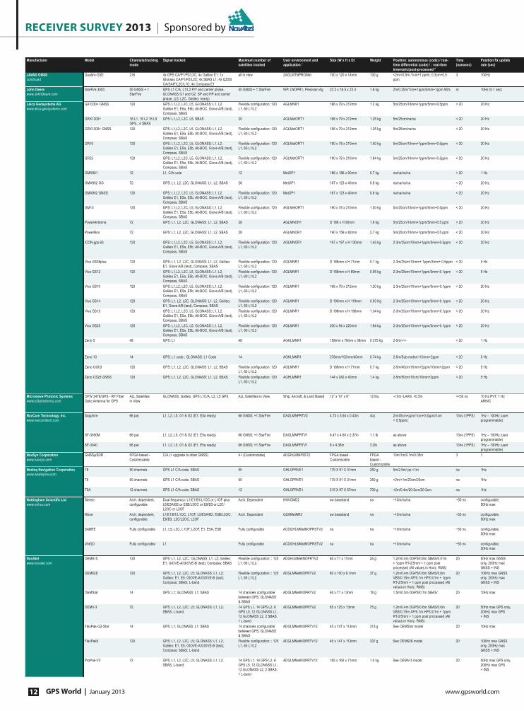
RECEIVER SURVEY 2013 | Sponsored by
GPS World | January 2013 www.gpsworld.com12
Manufacturer Model Channels/tracking
mode
Signal tracked Maximum number of
satellites tracked
User environment and
application 1
Size (W x H x D) Weight Position: autonomous (code) / real-
time differential (code) / ; real-time
kinematic/post-processed 2
Time
(nanosec)
3RVLWLRQ�À[�XSGDWH�
rate (sec)
JAVAD GNSS
continued
Quattro-G3D 216 4x GPS CA/P1/P2/L2C; 4x Galileo E1; 1x
Glonass CA/P1/P2/L2C; 4x SBAS L1; 4x QZSS
CA/SAIF/L2C/L1C; 4x Compass E1
all in view 2AGLMTNPROMet 100 x 120 x 14mm 130 g <2m/<0.5m /1cm+1 ppm/; 0.3cm+0.5
ppm
3 100Hz
John Deere
www.JohnDeere.com
StarFire 3000 55 GNSS + 1
StarFire
GPS L1 C/A, L1/L2 P/Y and carrier phase,
GLONASS G1 and G2, SP and HP and carrier
phase, (L5, L2C, Galileo; ready)
55 GNSS + 1 StarFire WP, LNOPR1, Precision Ag 22.3 x 16.5 x 22.3 1.6 kg 2m/0.25m/1cm+1ppm/5mm+1ppm 95% nr 10Hz (0.1 sec)
Leica Geosystems AG
www.leica-geosystems.com
GX1230+ GNSS 120 GPS: L1,L2, L2C, L5, GLONASS: L1, L2,
Galileo E1, E5a, E5b, Alt-BOC, Giove A/B (test),
Compass, SBAS
)OH[LEOH�FRQ¿JXUDWLRQ������
L1, 60 L1/L2
AGLMNR1 166 x 79 x 212mm 1.2 kg 5m/25cm/10mm+1ppm/5mm+0.5ppm < 20 20 Hz
GRX1200+ 16 L1, 16 L2 16 L5
GPS,; 4 SBAS
GPS: L1,L2, L2C, L5, SBAS 20 AGLMetORT1 166 x 79 x 212mm 1.25 kg 5m/25cm/na/na < 20 20 Hz
GRX1200+ GNSS 120 GPS: L1,L2, L2C, L5, GLONASS: L1, L2,
Galileo E1, E5a, E5b, Alt-BOC, Giove A/B (test),
Compass, SBAS
)OH[LEOH�FRQ¿JXUDWLRQ������
L1, 60 L1/L2
AGLMetORT1 166 x 79 x 212mm 1.25 kg 5m/25cm/na/na < 20 20 Hz
GR10 120 GPS: L1,L2, L2C, L5, GLONASS: L1, L2,
Galileo E1, E5a, E5b, Alt-BOC, Giove A/B (test),
Compass, SBAS
)OH[LEOH�FRQ¿JXUDWLRQ������
L1, 60 L1/L2
AGLMetORT1 190 x 78 x 210mm 1.50 kg 5m/25cm/10mm+1ppm/5mm+0.5ppm < 20 20 Hz
GR25 120 GPS: L1,L2, L2C, L5, GLONASS: L1, L2,
Galileo E1, E5a, E5b, Alt-BOC, Giove A/B (test),
Compass, SBAS
)OH[LEOH�FRQ¿JXUDWLRQ������
L1, 60 L1/L2
AGLMetORT1 190 x 78 x 210mm 1.84 kg 5m/25cm/10mm+1ppm/5mm+0.5ppm < 20 20 Hz
GMX901 12 L1, C/A code 12 MetOP1 186 x 186 x 60mm 0.7 kg na/na/na/na < 20 1 Hz
GMX902 GG 72 GPS: L1, L2, L2C, GLONASS: L1, L2, SBAS 28 MetOP1 167 x 123 x 40mm 0.8 kg na/na/na/na < 20 20 Hz
GMX902 GNSS 120 GPS: L1,L2, L2C, L5, GLONASS: L1, L2,
Galileo E1, E5a, E5b, Alt-BOC, Giove A/B (test),
Compass, SBAS
)OH[LEOH�FRQ¿JXUDWLRQ������
L1, 60 L1/L2
MetOP1 167 x 123 x 40mm 0.8 kg na/na/na/na < 20 20 Hz
GM10 120 GPS: L1,L2, L2C, L5, GLONASS: L1, L2,
Galileo E1, E5a, E5b, Alt-BOC, Giove A/B (test),
Compass, SBAS
)OH[LEOH�FRQ¿JXUDWLRQ������
L1, 60 L1/L2
AGLMetORT1 190 x 78 x 210mm 1.50 kg 5m/25cm/10mm+1ppm/5mm+0.5ppm < 20 20 Hz
PowerAntenna 72 GPS: L1, L2, L2C, GLONASS: L1, L2, SBAS 28 AGLMNOR1 D 186 x H 90mm 1.6 kg 5m/25cm/10mm+1ppm/5mm+0.5 ppm < 20 20 Hz
PowerBox 72 GPS: L1, L2, L2C, GLONASS: L1, L2, SBAS 28 AGLMNOR1 190 x 159 x 82mm 2.7 kg 5m/25cm/10mm+1ppm/5mm+0.5 ppm < 20 20 Hz
iCON gps 60 120 GPS: L1,L2, L2C, L5, GLONASS: L1, L2,
Galileo E1, E5a, E5b, Alt-BOC, Giove A/B (test),
Compass, SBAS
)OH[LEOH�FRQ¿JXUDWLRQ������
L1, 60 L1/L2
AGLMNOR1 197 x 197 x H 130mm 1.45 kg 2-3m/25cm/10mm+1ppm/3mm+0.5ppm < 20 20 Hz
Viva GS08plus 120 GPS: L1, L2, L2C, GLONASS: L1, L2, Galileo:
E1, Giove A/B (test), Compass, SBAS
)OH[LEOH�FRQ¿JXUDWLRQ������
L1, 60 L1/L2
AGLMNR1 D 186mm x H 71mm 0.7 kg 2-3m/25cm/10mm+ 1ppm/3mm+ 0.5ppm < 20 5 Hz
Viva GS12 120 GPS: L1,L2, L2C, L5, GLONASS: L1, L2,
Galileo E1, E5a, E5b, Alt-BOC, Giove A/B (test),
Compass, SBAS
)OH[LEOH�FRQ¿JXUDWLRQ������
L1, 60 L1/L2
AGLMNR1 D 186mm x H 89mm 0.95 kg 2-3m/25cm/10mm+1ppm/3mm+0.1ppm < 20 5 Hz
Viva GS10 120 GPS: L1,L2, L2C, L5, GLONASS: L1, L2,
Galileo E1, E5a, E5b, Alt-BOC, Giove A/B (test),
Compass, SBAS
)OH[LEOH�FRQ¿JXUDWLRQ������
L1, 60 L1/L2
AGLMNR1 166 x 79 x 212mm 1.20 kg 2-3m/25cm/10mm+1ppm/3mm+0.1ppm < 20 20 Hz
Viva GS14 120 GPS: L1, L2, L2C, GLONASS: L1, L2, Galileo:
E1, Giove A/B (test), Compass, SBAS
)OH[LEOH�FRQ¿JXUDWLRQ������
L1, 60 L1/L2
AGLMNR1 D 190mm x H 119mm 0.93 Kg 2-3m/25cm/10mm+1ppm/3mm+0.1ppm < 20 20 Hz
Viva GS15 120 GPS: L1,L2, L2C, L5, GLONASS: L1, L2,
Galileo E1, E5a, E5b, Alt-BOC, Giove A/B (test),
Compass, SBAS
)OH[LEOH�FRQ¿JXUDWLRQ������
L1, 60 L1/L2
AGLMNR1 D 198mm x H 196mm 1.34 kg 2-3m/25cm/10mm+1ppm/3mm+0.1ppm < 20 20 Hz
Viva GS25 120 GPS: L1,L2, L2C, L5, GLONASS: L1, L2,
Galileo E1, E5a, E5b, Alt-BOC, Giove A/B (test),
Compass, SBAS
)OH[LEOH�FRQ¿JXUDWLRQ������
L1, 60 L1/L2
AGLMNR1 200 x 94 x 220mm 1.84 kg 2-3m/25cm/10mm+1ppm/3mm+0.1ppm < 20 20 Hz
Zeno 5 48 GPS: L1 48 AGHLMNR1 158mm x 78mm x 38mm 0.375 kg 2-5m/-/-/- < 20 1 Hz
Zeno 10 14 GPS: L1 code ; GLONASS: L1 Code 14 AGHLMNR1 278mm/102mm/45mm 0.74 kg 2-5m/Sub-meter/-/10mm+2ppm < 20 5 Hz
Zeno GG03 120 GPS: L1, L2, L2C, GLONASS: L1, L2, SBAS )OH[LEOH�FRQ¿JXUDWLRQ������
L1, 60 L1/L2
AGLMNR1 D 186mm x H 71mm 0.7 kg 2-5m/40cm/10mm+2ppm/10mm+2ppm < 20 5 Hz
Zeno CS25 GNSS 120 GPS: L1, L2, L2C, GLONASS: L1, L2, SBAS )OH[LEOH�FRQ¿JXUDWLRQ������
L1, 60 L1/L2
AGHLMNR1 144 x 242 x 40mm 1.4 kg 2-5m/50cm/10cm/10mm+2ppm < 20 5 Hz
Microwave Photonic Systems
www.b2bphotonics.com
OFW 3478/GPS - RF Fiber
Optic Antenna for GPS
ALL Satellites
in View
GLONASS, Galileo, GPS L1C/A, L2, L5 GPS ALL Satellites in View Ship, Aircraft, & Land Based 12” x 10” x 6” 12 lbs. ~10m /LAAS: <0.5m <<50 ns 10 Hz PVT, 1 Hz
ARINC
NavCom Technology, Inc.
www.navcomtech.com
Sapphire 66 par. L1, L2, L5, G1 & G2 (E1, E5a ready) 66 GNSS; +1 StarFire DAGLMNPRTV2 4.73 x 3.94 x 0.43in 4oz 2m/45cm+ppm/1cm+0.5ppm/1cm
+ 0.5ppm)
13ns (1PPS) 1Hz – 100Hz (user
programmable)
SF-3050M 66 par. L1, L2, L5, G1 & G2 (E1, E5a ready) 66 GNSS; +1 StarFire DAGLMNPRTV1 6.47 x 4.60 x 2.37in 1.1 lb as above 13ns (1PPS) 1Hz – 100Hz (user
programmable)
SF-3040 66 par. L1, L2, L5, G1 & G2 (E1, E5a ready) 66 GNSS; +1 StarFire DAGLMNPRTV1 8 x 4.36in 3.2lb as above 13ns (1PPS) 1Hz – 100Hz (user
programmable)
NavSys Corporation
www.navsys.com
GNSSμSDR FPGA based -
Customizable
C/A (+ upgrade to other GNSS) 4+ (Customizable) ADGHLMNPRST2 FPGA based -
Customizable
FPGA
based -
Customizable
10m/1m/0.1m/0.05m 3 1
Nexteq Navigation Corporation
www.nexteqnav.com
T8 50 channels GPS L1 C/A code, SBAS 50 GHLOPRVE1 179 X 91 X 31mm 250 g 5m/2.5m/ pp <1m na 1Hz
T6 50 channels GPS L1 C/A code, SBAS 50 GHLOPRVE1 179 X 91 X 31mm 250 g <2m/<1m/20cm/20cm na 1Hz
T5A 12 channels GPS L1 C/A code, SBAS 12 GHLOPRVE1 215 X 97 X 57mm 700 g <2m/0.4m/20-2cm/20-2cm na 1Hz
1RWWLQJKDP�6FLHQWLÀF�/WG�
www.nsl.eu.com
Stereo Arch. dependent,
FRQ¿JXUDEOH
Dual frequency: L1/E1/B1/L1OC or L1OF plus
L5/E5A/B2 or E5B/L3OC or E6/B3 or L2C/
L2OC or L2OF
Arch. Dependent HNVCMD2 sw baseband na ~10m/na/na ~50 ns FRQ¿JXUDEOH��
50Hz max
Wave Arch. dependent,
FRQ¿JXUDEOH
L1/E1/B1/L1OC, L1OF, L5/E5A/B2, E5B/L3OC,
E6/B3, L2C/L2OC, L2OF
Arch. Dependent GLMMetNR2 sw baseband na ~10m/na/na ~50 ns FRQ¿JXUDEOH��
50Hz max
SABRE )XOO\�FRQ¿JXUDEOH L1, L5, L2C, L1OF, L2OF, E1, E5A, E5B )XOO\�FRQ¿JXUDEOH ACDGHLMMetNOPRSTV2 na na ~10m/na/na ~50 ns FRQ¿JXUDEOH��
50Hz max
JINGO )XOO\�FRQ¿JXUDEOH L1 )XOO\�FRQ¿JXUDEOH ACDGHLMMetNOPRSTV2 na na ~10m/na/na ~50 ns FRQ¿JXUDEOH��
50Hz max
NovAtel
www.novatel.com
OEM615 120 GPS: L1, L2, L2C,; GLONASS: L1, L2; Galileo:
E1; GIOVE-A/GIOVE-B (test); Compass; SBAS
)OH[LEOH�FRQ¿JXUDWLRQ��������
L1, 60 L1/L2
ADGHLMMetNOPRTV2 46 x 71 x 11mm 24 g 1.2m/0.4m DGPS/0.6m SBAS/0.01m
+ 1ppm RT-2/5mm + 1 ppm post
processed (All values in Horiz. RMS)
20 50Hz max GNSS
only, 200Hz max
GNSS + INS
OEM628 120 GPS: L1, L2, L2C, L5; GLONASS: L1, L2;
Galileo: E1, E5; GIOVE-A/GIOVE-B (test);
Compass; SBAS; L-band
)OH[LEOH�FRQ¿JXUDWLRQ��������
L1, 60 L1/L2
ADGLMMetNOPRTV2 60 x 100 x 9.1mm 37 g 1.2m/0.4m DGPS/0.6m SBAS/0.6m
VBS/0.15m XP/0.1m HP/0.01m + 1ppm
RT-2/5mm + 1 ppm post processed (All
values in Horiz. RMS)
20 100Hz max GNSS
only, 200Hz max
GNSS + INS
OEMStar 14 GPS: L1; GLONASS: L1; SBAS ���FKDQQHOV�FRQ¿JXUDEOH�
between GPS, GLONASS
& SBAS
ADGLMMetNOPRTV2 46 x 71 x 13mm 18 g 1.5m/0.5m DGPS/0.7m SBAS/ 20 10Hz max
OEMV-3 72 GPS: L1, L2, L2C, L5; GLONASS: L1, L2;
SBAS; L-band
14 GPS L1, 14 GPS L2, 6
GPS L5, 12 GLONASS L1,
12 GLONASS L2, 2 SBAS,
1 L-band
ADGLMMetNOPRTV2 85 x 125 x 13mm 75 g 1.2m/0.4m DGPS/0.6m SBAS/0.6m
VBS/0.15m XP/0.1m HP/0.01m + 1ppm
RT-2/5mm + 1 ppm post processed (All
values in Horiz. RMS)
20 50Hz max GPS only,
200Hz max GPS
+ INS
FlexPak-G2-Star 14 GPS: L1; GLONASS: L1; SBAS ���FKDQQHOV�FRQ¿JXUDEOH�
between GPS, GLONASS
& SBAS
ADGLMMetNOPRTV12 45 x 147 x 113mm 313 g See OEMStar model 20 10Hz max
FlexPak6 120 GPS: L1, L2, L2C, L5; GLONASS: L1, L2;
Galileo: E1, E5; GIOVE-A/GIOVE-B (test);
Compass; SBAS; L-band
)OH[LEOH�FRQ¿JXUDWLRQ��������
L1, 60 L1/L2
ADGLMMetNOPRTV12 45 x 147 x 113mm 337 g See OEM628 model 20 100Hz max GNSS
only, 200Hz max
GNSS + INS
ProPak-V3 72 GPS: L1, L2, L2C, L5; GLONASS: L1, L2;
SBAS; L-band
14 GPS L1, 14 GPS L2, 6
GPS L5, 12 GLONASS L1,
12 GLONASS L2, 2 SBAS,
1 L-band
ADGLMMetNOPRTV12 185 x 160 x 71mm 1.0 kg See OEMV-3 model 20 50Hz max GPS only,
200Hz max GPS
+ INS

Sponsored by | receiver survey 2013
www.gpsworld.com January 2013 | GPS World 13
Cold start 3 Warm start 4 Reacquisition 5 No. of ports Port type Baud rate Operating temperature
(degrees Celsius)
Power source Power consumption
(Watts)
Antenna type 6 Description or Comments
<35s <5s <1s 221222111 RS232; RS232/RS422; USB; CAN;
1PPS; Event Marker; IRIG; Ethernet;
Ext. Freq In/Out
2,400–115,200 –40 to +65 ext 5.2 E 2048MB memory
<60s <50s <20s 4 1xCAN/ 3xRS232 2,400–115,200 –40 to +65 9 to 26 V DC 7.2 Internal dipole, Ext Integrated 6-axis terrain compensation, proprietary RTK-
Extend operating mode, compatibility with space-based
differential corrections network (StarFire)
50s 35s 0.5s 4 4 RS-232, 1 Power, 1 TNC, 1 PPS Out,2
Event-Optional
2,400–115,200 –40 to +65 ext/int 3.2 AR10/AS10 triple frequency or
AR25/AR20 choke ring
Triple frequency geodetic and RTK GNSS receiver.
50s 35s 0.5s 5 4 RS-232; 2 power; 1 TNC, Ethernet, PPS,
ext osc, event
2,400–115,200 –40 to +65 ext/int 3.2 AR10/AS10 triple frequency or
AR25/AR20 choke ring
Permanent dual frequency GPS receiver w/ Ethernet.
50s 35s 0.5s 5 4 RS-232; 2 power; 1 TNC, Ethernet, PPS,
ext osc, event
2,400–115,200 –40 to +65 ext/int 3.2 to 3.9 AR10/AS10 triple frequency or
AR25/AR20 choke ring
Permanent triple frequency GNSS receiver w/ Ethernet.
50s 35s 0.5s 5 1 (2 port) power, 1 RS-232, UART, USB,
TNC, Ethernet, ext osc
4800 – 115’200 –40 to +65 ext 3.1 to 3.5 AR10/AS10 triple frequency or
AR25/AR20 choke ring
Permanent triple frequency GNSS receiver w/ Ethernet.
50s 35s 0.5s 7 1 (2 port) power, 2 RS-232, 1 UART, 2
USB, 1 Ethernet, 1 bluetooth (plus TNC,
PPS, event, Oscillator)
2,400–230,400 –40 to +65 ext/int 3.1 to 3.3 AR10/AS10 triple frequency or
AR25/AR20 choke ring
Permanent triple frequency GNSS receiver w/ Ethernet.
<120 s * <45 s* <10 s 1 1 LEMO-1 connector, 8 pin 2,400–230,400 –40 to +65 ext 1.7 Integrated Leica AT501 microstrip
antenna with built-in groundplane
Single frequency GPS smart antenna for structural
monitoring
50s 35s 0.5s 2 2 RS-232, 2 Power, 1 TNC, 1 PPS output 2,400–115,200 –40 to +65 ext 1.7 AR10/AS10 triple frequency or
AR25/AR20 choke ring
Dual frequency GNSS receiver for structural monitoring
50s 35s 0.5s 2 2 RS-232, 2 Power, 1 TNC, 1 PPS output 2,400–115,200 –40 to +65 ext 1.7 AR10/AS10 triple frequency or
AR25/AR20 choke ring
Triple frequency GNSS receiver for structural monitoring
50s 35s 0.5s 5 1 (2 port) power, 1 RS-232, UART, USB,
TNC, Ethernet, ext osc
2,400–115,200 –40 to +65 ext 3.1 to 3.5 AR10/AS10 triple frequency or
AR25/AR20 choke ring
Permanent triple frequency GNSS receiver w/ Ethernet
for monitoring
50s 35s 0.5s 1 1 RS-232/Power in, 1x RS422/Power
in, Bluetooth
2,400–115,200 –40 to +60 ext/int 3.8 Internal Dual frequency RTK GNSS receiver for site survey and
machine navigation
50s 35s 0.5s 5 2 RS-232, 1 Power/RS-232, 1 RS232/
RS422, 2 CAN, 1 TNC
2,400–115,200 –30 to +60 ext 3.8 MNA1202 GG Dual frequency RTK GNSS machine navigation receiver
50s 35 s 0.5s 6 1 combined RS-232/PWR in/PWR out, 1
USB Host, 1 UART &USB, 1 TNC, 1 QN,
1 Bluetooth; 1 USB Host; 1 UART&USB;
1 Bluetooth
2,400–115,200 –40 to +65 ext/int 6.0 Internal or external (e.g.
MNA1202 GG)
Triple frequency construction RTK GNSS receiver; including
build in Display and Keyboard; external GNSS antenna
support to be used on a construction machine
50s 35s 0.5s 2 Combined (RS-232, Power, USB), 1
Bluetooth
2,400–115,200 –40 to +65 ext/int 2.0 Internal Dual frequency geodetic and RTK GNSS receiver
50s 35s 0.5s 2 Combined (RS-232, Power, USB), 1
Bluetooth
2,400–115,200 –40 to +65 ext/int 1.8 Internal Triple frequency geodetic and RTK GNSS receiver
50s 35s 0.5s 4 2 RS-232, 1 Combined (RS-232, USB), 1
Power, 1 TNC, 1 Bluetooth
2,400–115,200 –40 to +65 ext/int 3.2 AR10/AS10 triple frequency or
AR25/AR20 choke ring
Triple frequency geodetic and RTK GNSS receiver
50s 35s 0.5s 2 1 RS-232, 1 combined (RS-232, Power,
USB), 1 UART &USB, 1 Bluetooth
2,400–115,200 –40 to +65 ext/int 2.0 Internal Dual frequency geodetic and RTK GNSS receiver
50s 35s 0.5s 4 1 RS-232, 1 combined (RS-232, Power,
USB), 1 UART &USB, 1 Bluetooth
2,400–115,200 –10 to +50 ext/int 3.2 Internal Triple frequency geodetic and RTK GNSS receiver
50s 35s 0.5s 8 2 RS-232, 1 Combined (RS-232, USB), 1
UART &USB, 1 PPS, 2 Event, 1 Mini USB,
1 Power, 1 TNC, 1 Bluetooth
ext/int 3.4 AR10/AS10 triple frequency or
AR25/AR20 choke ring
Triple frequency geodetic and RTK GNSS receiver
<120 s * <35 s* <10 s 2 1 Bluetooth, 1 USB (SnapOn module) ext/int 1.3 Internal Single Frequency Handheld GPS receiver
2,400–115,200 –40 to +65
2,400–115,200 –40 to +65
<120 s * <35 s* <10 s 4 1 Bluetooth, Wireless LAN, 1 RS-232, 1
Combined (RS-232, USB)
2,400–115,200 –23 to +60 ext/int 2.5 Internal/External Single Frequency Handheld GNSS receiver
50s 35s 0.5s 2 Combined (RS-232, Power, USB), 1
Bluetooth
100 Kbps ARINC –55 to +80 ext/int 2.0 Internal Dual frequency geodetic and RTK GNSS receiver
50s 35s 0.5s 5 2 USB, 1 RS-232, LAN, Power, 1
Bluetooth
RS232: 9.6kbps – 115kbps;
USB: up to 12Mbps;
Ethernet: up to 100Mbps;
Bluetooth: up to 230.4kbps
-40 to +85 ext/int 7-10 Internal/External Dual frequency geodetic and RTK GNSS receiver
<<75 s <20 s <1 s 1 8 I/P, 3 O/P ARINC H/L,; 1 RS-232 RS232: 9.6kbps – 115kbps;
USB: up to 12Mbps;
Ethernet: up to 100Mbps;
Bluetooth: up to 230.4kbps
-40 to +70 ext 14W Active, RTCA DO-228 Change
1 compliant
ARINC-743 Compliant sensor
<60 s <50 s <20 s 5 2 x RS232 (1 con¿gurable to RS422); 1
x USB 2.0 (host or device); 1 x Ethernet
(10T/100T); 1 x Bluetooth
RS232: 9.6kbps – 115kbps;
USB: up to 12Mbps;
Ethernet: up to 100Mbps;
Bluetooth: up to 230.4kbps
-40 to +70 ext 6W typical Crossed dipole (ER) Latest generation of John Deere technology
<60 s <50 s <20 s 5 as above FPGA based -
Customizable
FPGA based -
Customizable
ext < 4 W Crossed dipole (ER) Integrated StarFire/RTK Extend multi-frequency receivers
<60 s <50 s <20 s 5 as above 300-115,200 I10 to +60 hot swappable
batteries
< 4 W Crossed dipole (ER) Integrated StarFire/RTK Extend multi-frequency receivers
15mn max 30 sec <10s FPGA based -
Customizable
FPGA based - Customizable 300-115,200 I10 to +60 FPGA based -
Customizable
FPGA based -
Customizable
Selectable
29s 29s <1s 2 USB/Blue tooth 300-115,200 I20 to +60 battery/ext.USB 0.5W with the GPS on intertnal/external Rugged and ready-to-use handheld with GIS data
collection SW
26s 26s <1s 2 USB/Blue tooth Fully con¿gurable battery/ext USB 0.5W with the GPS on intertnal/external RTK, i-PPP data service, Post processing,GIS data
collection SW preinstalled
60s 45s <1s 2 USB/Blue tooth Fully con¿gurable battery/ext USB <2W intertnal/external RTK, i-PPP data service, Post processing ,GIS data
collection SW preinstalled
<40s <35s <2s Arch. dependent IP, USB Fully con¿gurable ext Arch. dependent E Dual frequency GNSS front end to be used with, for
example, software de¿ned radio GNSS receiver. Stereo
contains two Front Ends (with common clock).
<40s <35s <2s Arch. dependent IP, USB, LVDS Fully con¿gurable ext Arch. dependent E Multiple frequency direct bandpass GNSS front end to
be used with, for example, software de¿ned radio GNSS
receiver.
<40s <35s <2s Fully con¿gurable Fully con¿gurable 300 to 921,600 bps;; 1
Mbps; 12 Mbps
-40 to +85 na na na Pure SW receiver for GPS, GLONASS and GALILEO. Single
or combined constellations. Snap-shot, kalman ¿ltering, PPP
positioning. Real-time or post-processing on digital IF.
<40s <35s <2s Fully con¿gurable Fully con¿gurable 300 to 921,600 bps; 300 to
921,600 bps;; 1 Mbps; 12
Mbps; 10/100 Mbps
-40 to +85 na na na SW GPS receiver for detection of GPS SPS SIGNAL
INTERFERENCE. Uses pre-correlation, correlation and
post-correlation techniques.
50s 35s 0.5s 6 3 x LV-TTL, 2 x CAN, 1 x USB2.0 300 to 230,400 bps;
12 Mbps
-40 to +85 3.3 V DC 1W (typical) Active (E) RoHS-compliant; RT-2, GL1DE, PDP, RAIM, ALIGN and
SPAN software features available
50s 35s 0.5s 7 1 x RS-232 or RS-422, 2 x LV-TTL, 2 x
CAN, 1 x USB2.0, 1 x Ethernet
300 to 921,600 bps; 300
to 921,600 bps; 300 to
230,400 bps; 1 Mbps;
5 Mbps
-40 to +85 3.3 V DC 1.3W (typical) Active (E) RoHS-compliant; RT-2, OmniSTAR VBS/HP/XP, GL1DE,
PDP, RAIM, ALIGN and SPAN software features available
65s 35s <1.0s 3 2 x LV-TTL; 1 x USB2.0 300 to 921,600 bps; 300 to
230,400 bps;; 12 Mbps
-40 to +85 3.15 to 5.25 VDC 0.36W GPS; 0.45W
GLONASS
Active (E) RoHS-compliant; GL1DE and PDP software features
available
60s 35s 0.5s 6 1 x RS-232 or RS-422; 1 x RS-232 or LV-
TTL; 1 x LV-TTL; 2 x CAN, 1 x USB1.1
300 to 921,600 bps; 300 to
921,600 bps;; 12 Mbps; 1
Mbps; 10/100 Mbps
-40 to +75 4.5 to 18 VDC 2.1W (typical) Active (E) RoHS-compliant; RT-2, OmniSTAR VBS/HP/XP, GL1DE,
PDP, ALIGN, and SPAN software features available
65s 35s <1.0s 3 1 x RS-232; 1 x RS-232 or RS-422,
1 x USB1.1
300 to 921,600 bps; 300
to 230,400 bps; 300 to
230,400 bps; 5 Mbps
-40 to +75 6 to 18 V DC 0.6W (typical); Active (E) RoHS-compliant; GL1DE and PDP software features
available
50s 35s 0.5s 5 1 x RS-232, 1 x RS-232 or RS-422, 1 x
USB2.0, 1 x CAN, 1 x Ethernet
300 to 921,600 bps; 300
to 230,400 bps; 300 to
230,400 bps; 5 Mbps,
10/100 Mbps
-40 to +75 6 to 36 V DC 1.8W (typical) Active (E) RoHS-compliant; RT-2, OmniSTAR VBS/HP/XP, GL1DE,
PDP, RAIM, ALIGN and SPAN software features available
60s 35s 0.5s 4 3 x RS-232 or 2 x RS-422 plus 1 x RS-
232; 1 x USB1.1
300 to 921,600 bps; 12
Mbps; 10/100 Mbps
-40 to +65 6 to 18 V DC ; 2.8 W typical Active (E) RoHS-compliant; RT-2, OmniSTAR VBS/HP/XP, GL1DE,
PDP, ALIGN, and SPAN software features available
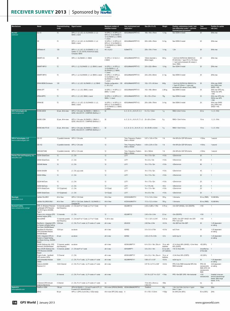
RECEIVER SURVEY 2013 | Sponsored by
GPS World | January 2013 www.gpsworld.com14
Manufacturer Model Channels/tracking
mode
Signal tracked Maximum number of
satellites tracked
User environment and
application 1
Size (W x H x D) Weight Position: autonomous (code) / real-
time differential (code) / ; real-time
kinematic/post-processed 2
Time
(nanosec)
3RVLWLRQ�À[�XSGDWH�
rate (sec)
NovAtel
continued
DL-V3 72 GPS: L1, L2, L2C, L5; GLONASS: L1, L2;
SBAS; L-band
14 GPS L1, 14 GPS L2, 6
GPS L5, 12 GLONASS L1,
12 GLONASS L2, 2 SBAS,
1 L-band
ADGLMMetNOPRTV12 185 x 163 x 76mm 1.3 kg See OEMV-3 model 20 50Hz max
SE 72 GPS: L1, L2, L2C, L5; GLONASS: L1, L2;
SBAS; L-band
14 GPS L1, 14 GPS L2, 6
GPS L5, 12 GLONASS L1,
12 GLONASS L2, 2 SBAS,
1 L-band
ADGLMMetNOPRTV12 200 x 248 x 76mm 3.4 kg See OEMV-3 model 20 20Hz max
GPStation-6 120 GPS: L1, L2, L2C, L5; GLONASS: L1, L2;
Galileo: E1, E5; GIOVE-A/GIOVE-B (test);
Compass; SBAS
40 L1/L2/L5 ALMetOT12 235 x 154 x 71mm 1.4 kg 1.2m 20 50Hz max
SMART-AG 36 GPS: L1; GLONASS: L1; SBAS 14 GPS L1; 12 GLO L1;
2 SBAS
ADGLMMetNOPRTV12 155mm diameter x
68mm height
500 g 1.2m/0.4m DGPS/0.8m SBAS/0.2m
RT-20/0.02m + 1ppm RT-2 L1TE/ 5mm
+ 1 ppm post processed (All values in
Horiz. RMS)
20 20Hz max
SMART-MR10 72 GPS: L1, L2; GLONASS: L1, L2; SBAS; L-band 14 GPS L1, 14 GPS L2,
12 GLONASS L1, 12
GLONASS L2, 2 SBAS,
1 L-band
ADGLMMetNOPRTV12 233 x 232 x 89mm 1.9 kg See OEMV-3 model 20 20Hz max
SMART-MR15 72 GPS: L1, L2; GLONASS: L1, L2; SBAS; L-band 14 GPS L1, 14 GPS L2,
12 GLONASS L1, 12
GLONASS L2, 2 SBAS,
1 L-band
ADGLMMetNOPRTV12 233 x 233 x 90mm 2.1 kg See OEMV-3 model 20 20Hz max
SPAN MEMS Enclosure 120 GPS: L1, L2, L2C; GLONASS: L1, L2; SBAS )OH[LEOH�FRQ¿JXUDWLRQ��������
L1, 60 L1/L2
ADGLMMetNOPRTV12 152 x 137 x 50.5mm 640g 1.2m/0.4m DGPS/0.6m SBAS/0.01m
+ 1ppm RT-2/5mm + 1 ppm post
processed (All values in Horiz. RMS)
20 20Hz max GNSS
only, 200Hz max
GNSS + INS
SPAN-CPT 72 GPS: L1, L2, L2C; SBAS; L-band 14 GPS L1, 14 GPS L2, 2
SBAS, 1 L-band
ADGLMMetNOPRTV12 152 x 168 x 89mm 2.36 kg See OEMV-3 model 20 20Hz max GPS only,
100Hz max GPS
+ INS
SPAN-MPPC 72 GPS: L1, L2, L2C; SBAS; L-band 14 GPS L1, 14 GPS L2, 2
SBAS, 1 L-band
ADGLMMetNOPRTV12 85 x 125 x 27mm 75g See OEMV-3 model 20 20Hz max GPS only,
200Hz max GPS
+ INS
SPAN-SE 72 GPS: L1, L2, L2C, L5; GLONASS: L1, L2;
SBAS; L-band
14 GPS L1, 14 GPS L2, 6
GPS L5, 12 GLONASS L1,
12 GLONASS L2, 2 SBAS,
1 L-band
ADGLMMetNOPRTV12 200 x 248 x 76mm 3.4 kg See OEMV-3 model 20 20Hz max GNSS
only, 200Hz max
GNSS + INS
NVS Technologies AG
www.nvs-gnss.com
NV08C-MCM 32 par., All-in-view GPS L1 C/A code, GLONASS L1, SBAS L1,;
QZSS, GALILEO E1, COMPASS (BeiDou) L1
32 A, C, G, H, L, M, N, R, V, 2 9 x 12 x 1.5mm 1 g RMS:<2.5m/<1m/na 25 ns 1, 2, 5, 10Hz
NV08C-CSM 32 par., All-in-view GPS L1 C/A code, GLONASS L1, SBAS L1,
QZSS, GALILEO E1, COMPASS (BeiDou) L1
32 A, C, G, H, L, M, N, R, T, V, 2 20 x 26 x 2.5mm 5 g RMS:<1.5m/<1m/na 15 ns 1, 2, 5, 10Hz
NV08C-Mini PCI-E 32 par., All-in-view GPS L1 C/A code, GLONASS L1, SBAS L1,
QZSS, GALILEO E1, COMPASS (BeiDou) L1
32 A, C, D, G, H, L, M, N, R, V, 2 30 x 50.95 x 4.2mm 7 g RMS:<1.5m/<1m/na 15 ns 1, 2, 5, 10Hz
ORCA Technologies, LLC
www.orcatechnologies.com
GS-101 12 parallel channels GPS L1 C/A code 12 Time, Frequency, Position -
Static or Mobile
3.07 x 1.06 x 4.72in 1 lb <9m 90%/2m CEP 50%/na/na <100ns 1 second
GS-102 12 parallel channels GPS L1 C/A code 12 Time, Frequency, Position -
Static or Mobile
4.06 x 2.09 x 4.72in 1 lb <9m 90%/2m CEP 50%/na/na <100ns 1 second
ORCA637VME 12 parallel channels GPS L1 C/A code 12 Time, Frequency, Position -
Static or Mobile
6U x 160mm 1 lb <9m 90%/2m CEP 50%/na/na <100ns 1 second
Precise Time and Frequency, Inc.
ZZZ�SW¿QF�FRP
3203A GlobalTyme 12 L1, C/A 12 LOT1 19 x 1.75 x 12in <10 lb <25m/nr/nr/nr 20 1
3204A GlobalTyme 12 L1, C/A 12 LOT1 19 x 3.5 x 12in <10 lb <25m/nr/nr/nr 20 1
3203AB Mobile 12 L1, C/A 12 LOT1 19 x 1.75 x 12in <10 lb <25m/nr/nr/nr 60 1
3203A SAASM 12 L1, C/A, p(y) code 12 LOT1 19 x 1.75 x 12in <10 lb <25m/nr/nr/nr 40 1
3203A WiMax 12 L1, C/A 12 LOT1 19 x 1.75 x 12in <10 lb <25m/nr/nr/nr 20 1
3223A NetTyme 12 L1, C/A 12 LOT1 19 x 1.75 x 12in <10 lb <25m/nr/nr/nr 20 1
3225A NetTyme 12 L1, C/A 12 LOT1 7 x 1.75 x 9in <5 lb <25m/nr/nr/nr 20 1
3207A GlobalTyme 12+12(optional) L1, C/A 12+12(opt) LOT1 19 x 1.75 x 16in <10 lb <25m/nr/nr/nr 20 1
3208A GlobalTyme 12+12(optional) L1, C/A 12+12(opt) LOT1 19 x 3.5 x 16in <10 lb <25m/nr/nr/nr 20 1
Racelogic
www.labsat.co.uk
LabSat; RLLSR01 All in View GPS L1 C/A Code All in View ACDGHLMNOTV1 17.0 x 12.8 x 3.8cm 750 g 1.5m/na/na 50 ns; (RMS) 16.368 MHz
LabSat; RLLSR02-GNL1 All in View GPS L1 C/A Code, Galileo E1, GLONASS L1,
Compass B1
All in View ACDGHLMNOTV1 17.0 x 12.3 x 4.6cm 750 g 1.5m/na/na 50 ns; (RMS) 16.368 MHz
Rockwell Collins
www.rockwellcollins.com/gs/
MPE–S, Miniature Precision
Lightweight GPS Receiver
(PLGR) Engine (SAASM)
Type II
12 channels parallel,
dual frequency
L1, C/A and P or Y Code; L2, P or Y Code 12 ADLMNTV2 2.45 x 0.285 x 1.76in 0.75 oz <4m CEP (WAGE), <2m (SDGPS) <100 1
Polaris Link, miniature GPS
receiver engine (SPS)
12 channels L1, C/A 12 ADLMNTV2 2.45 x 0.6 x 3.4in 2.5 oz <2m (SDGPS) <100 1
MicroGRAM 12 channels parallel,
dual frequency
L1, C/A and P or Y Code; L2, P or Y Code 12; All in view 1.0” x 1.25” x 0.275” 0.25 oz DGPS: <2m CEP; WAGE <4m CEP;
PPS <12m CEP
<100 1
NavStorm+, Integrated GPS-
AJ System w/Digital Nulling,
Gun Hard, SAASM-Based
12/24 par. L1, C/A, P or Y–code; L2, P–code or Y–code all in view ADLNO2 2.62 Dia x 0.9in <0.5 lb <8m SEP/na/<16m SEP 30 1–25 dependent
on aiding
NavStrike-24–Munitions
GPS Embedded Module,
SAASM-Based
12/24 par. as above all in view ADNS2 3.5 x 3.0 x 0.75in <0.5 lb na/3.7m/nr 30 1–25 dependent
on aiding
IGAS, Integrated GPS-AJ
System w/ Digital Nulling
and Beam-forming, SAASM-
Based
24 par. as above all in view ADNS2 4.35 x 5.15 x 0.9in <2 lb na/2m typ./nr 30 1–25 dependent
on aiding
DAGR (Defense Adv. GPS
Receiver) SAASM-Based
12 channel, parallel,
dual frequency
as above all in view ADGHLMNPTV1 6.4 x 3.5 x 1.6in, 25cu in 15 oz. with
batteries
<5.1m Horiz 95% (WAGE), <2.4m Horiz
95% (DGPS)
<52 (95%) 1
Micro DAGR (Defense Adv.
GPS Receiver) SAASM
Based
12 channel, parallel L1, C/A and P or Y code all in view ADHLMNPT1 3.9 x 2.6 x 1.4in 6.5 oz with;
L91 batteries
<18.1m Horiz 95% 8QYHUL¿HG�DV�
of this date
1
Polaris Guide ; handheld
GPS receiver (SPS)
12 Channel L1, C/A all in view ADGHLMNPTV1 6.4 x 3.5 x 1.6in, 25cu in 15 oz. w/
batteries
<2.4m Horiz 95% (DGPS) <52 (95%) 1
GPS Embedded Module
(GEM)
12/24 L1, C/A, P or Y code, L2, P–code or Y–code all in view ADLMNPRSTV1 5.88 x 5.7 x 0.57 <0.8 lb na/2m typ./nr 30 1–25 dependent
on aiding
Airborne SAASM
Reciever 3.3
12/24 Channel L1, C/A, P or Y code, L2, P–code or Y–code all in view 4.9” W x 3.2” H x 0.80” <0.6 lb PPS:<5.6m RMS horizontal SPS:<6m
RMS horizontal
PPS:<30
nanoseconds
RMS; SPS:<45
nanoseconds
RMS
4-25 dependent
on aiding
DIGAR 24 channel L1, C/A, P or Y code, L2, P–code or Y–code all in view 8.0” W x 2.27” H x 12.0” <11lbs PPS: <5m SEP; SPS: <6m horizontal <100
nanoseconds
Unaided: once-per-
second pseudorange
based, delta range
based, 10 Hz
4 Element GPS Anti-jam
Antenna Electronics
4 Channel L1, C/A, P or Y–code; L2, P–code or Y–code na 17cm (W) x 20cm (L)
x 5cm (H)
<5lbs na na
Septentrio
www.septentrio.com
AsteRx-m OEM 136 par. GPS+GLONASS L1, C/A and P-code & CP; L2,
P-code & CP; WAAS/EGNOS
All in view (GPS/GLONASS) ADGHLMMetNOPRTV2 70x48mm 40g 1.5m (1s)/ 0.6m (1s)/1cm +1 ppm/
5mm + 1 ppm
10sec 25Hz
AiRx2 64 par GPS L1; (GPS L5 and GAL L1-E5a ready) All in view GPS (GAL ready) A 61 x 100 x 13.5mm <100gr 5m (95%)/3m (95%) 50 ns (95%) 20Hz

Sponsored by | receiver survey 2013
www.gpsworld.com January 2013 | GPS World 15
Cold start 3 Warm start 4 Reacquisition 5 No. of ports Port type Baud rate Operating temperature
(degrees Celsius)
Power source Power consumption
(Watts)
Antenna type 6 Description or Comments
60s 35s 0.5s 6 3 x RS-232 or 2 x RS-422 plus 1 x
RS-232; USB1.1, Ethernet, Bluetooth,
Compact Flash card drive
9,600 to 230,400 bps;
12 Mbps
-40 to +65 9 to 28 V DC 3.5 W typical Active (E) RoHS-compliant; RT-2, OmniSTAR VBS/HP/XP, GL1DE,
PDP, and ALIGN software features available
60s 35s 0.5s 10 4 x RS-232 or RS-422; 1 x UART COM
Port; 1 x USB 2.0 Host; 1 x USB 2.0
Device; 1 x Ethernet; 1 x SD card drive; 1
x IMU Connection
300 to 460,800 bps;;
1 Mbps
-40 to +75 9 to 28 VDC 10W (typical) Active (E) (dual antenna input
optional)
RoHS-compliant; RT-2, OmniSTAR VBS/HP/XP, GL1DE,
PDP, and ALIGN software features available
60s 35s 0.5s 4 3 x RS-232 or RS-422, 1 x USB2.0 300 to 230,400 bps; ;
1 Mbps;
-40 to +70 4.5 to 18 V DC 6W (typical) Active (E) Multi-frequency multi-constellation GNSS Ionospheric
Scintillation and TEC Monitor (GISTM); receiver. Provides
50Hz phase and amplitude scintillation measurements (S4,
σф), TEC and TEC phase.
60s 35s 0.5s 4 2 x RS-232; 1 x CAN NMEA2000; 1 x
Bluetooth (optional)
300 to 230,400 bps; ;
1 Mbps;
-40 to +65 8 to 36 V DC 2.5W (typical) Patch RoHS-compliant; RT-2 L1TE, GL1DE, and ALIGN software
features available
65s 35s 0.5s 6 1 x RS-232 or RS-422; 2 x RS-232; 1
x CAN NMEA2000; 1 x Bluetooth; 1 x
Emulated Radar
300 to 921,600 bps; 1
Mbps; 12 Mbps
-40 to +65 9 to 36 VDC 3.7W (typical) Pinwheel RoHS-compliant; RT-2, OmniSTAR VBS/HP/XP, GL1DE,
PDP, and ALIGN software features available
65s 35s 0.5s 6 1 x RS-232 or RS-422; 1 x RS-232; 1
x CAN NMEA2000; 1 x Bluetooth; 1 x
Ground speed output, 1 x GPRS/HSDPA
or CDMA radio
300 to 921,600 bps; 1
Mbps; 5 Mbps
-40 to +65 9 to 36 VDC 4.5W (typical) Pinwheel RoHS-compliant; RT-2, OmniSTAR VBS/HP/XP, GL1DE,
PDP, and ALIGN software features available
50s 35s 0.5s 4 1 x RS-232; 1 x RS-232 UART COM Port;
1 x CAN; 1 x USB1.1
300 to 921,600 bps; 12
Mbps; 10/100 Mbps
-40 to +85 10 to 30 VDC TBD Active (E) RoHS-compliant; RT-2 software features available
60s 35s 0.5s 4 2 x RS-232 UART COM Port; 1 x CAN;
1 x USB1.1
300 to 921,600 bps; 12
Mbps; 10/100 Mbps
-40 to +65 9 to 18 VDC 15W (max) Active (E) RoHS-compliant; RT-2, and OmniSTAR VBS/HP/XP
software features available
60s 35s 0.5s 9 4 x RS-232 or RS-422; 1 x UART COM
Port; 1 x USB 2.0 Host; 1 x USB 2.0
Device; 1 x Ethernet; 1 x IMU Connection
up to 230 400 bps -30 to +85 °C 9 to 30 VDC 8W (typical) Active (E) RoHS-compliant; RT-2, and OmniSTAR VBS/HP/XP
software features available
60s 35s 0.5s 10 4 x RS-232 or RS-422; 1 x UART COM
Port; 1 x USB 2.0 Host; 1 x USB 2.0
Device; 1 x Ethernet; 1 x SD card drive; 1
x IMU Connection
up to 230 400 bps -40 to +85 °C 9 to 28 VDC 10W (typical) Active (E) (dual antenna input
optional)
RoHS-compliant; RT-2, and OmniSTAR VBS/HP/XP
software features available
30s 30s <1s 2 2xUART; 2xSPI; 1xTWI (I2C compatible);
1PPS
up to 230 400 bps -40 to +85 °C ext. 150mW (GNSS)/100mW
(GPS)/20mW
(GNSS)/16mW
(GPS)/5mW (Sleep mode)
Active & Passive (auto-switching
current detector)
In-car & PNDs, asset & personal tracking, Telematics & anti-
theft, surveillance & security + other mobile applications/A-
GNSS, dead reckoning & raw data output
25s 25s <1s 2 2xUART; 1xSPI; 1xTWI (I2C compatible);
1PPS
9600 bps - 115200 bps 0 to 50 ext. 180mW (GNSS)/120mW
(GPS)/24mW
(GNSS)/18mW
(GPS)/5mW (Sleep mode)
Active Fleet mgmt, Telematics & anti-theft, in-car & PNDs, asset
and personal tracking, surveillance & security/LTE, WiMAX,
Wi-Fi & cell. base station timing/A-GNSS, dead reckoning,
raw data output/Flash memory + power mgmt
25s 25s <1s 1/NMEA (default)
or binary protocol
PCI-Express standard bus/virtual COM
port device
9600 bps - 115200 bps 0 to 50 ext. 200mW (GNSS)/140mW
(GPS)/0.4mA (Sleep
mode)
Active & Passive (auto-switching
current detector)
Rugged notebook PCs, tablets & handheld computers.
Telematics & marine navigation. Surveillance, security and
public safety. GIS, survey, machine control & PrecisionAg/A-
GNSS, dead reckoning, raw data output/Flash memory
+ power mgmt.;
<20min <1min <1s 3 2 serial/1 USB 0 to 50 external 30 mw active Small portable GPS Receiver providing IRIG time, pulse
rates, event capture and position over serial and USB ports.
Can be portable with optional battery.
<20min <1min <1s 3 2 serial/1 USB 1,200–57,600 0 to +50 external 30 mw active Small portable GPS Receiver providing IRIG time, pulse
rates, event capture and position over serial and USB ports.
Powered by external supply or internal rechargeable battery.
<20min <1min <1s 1,200–57,600 0 to +50 bus active VME Time & Frequency Processor
<20min <5min 1s 2 RS-232, 100baseT 1,200–57,600 0 to +50 Internal 90–264
AC
<10 35 dBi, 5 V DC Multiple frequency outputs, IRIG B, Low phase noise
<20min <5min 1s 2 RS-232, 100baseT 1,200–57,600 0 to +50 Internal 90–264
AC
<10 35 dBi, 5 V DC as above
<20min <5min 1s 2 RS-232, 100baseT 1,200–57,600 0 to +50 Internal 90–264
AC Internal 20 -
70VDC (optional)
<10 35 dBi, 5 V DC Multiple frequency outputs, IRIG B, Low phase noise
<20min <5min 5s 2 RS-232, 100baseT 1,200–57,600 0 to +50 Internal 90–264
AC
<10 35 dBi, 5 V DC Multiple frequency outputs, IRIG B, Low phase noise
<20min <5min 1s 2 RS-232, 100baseT 1,200–57,600 0 to +50 Internal 90–264
AC 20 - 70VDC
(optional)
<10 35 dBi, 5 V DC 3x10MHz sine (low phase noise) + 3 x 1PPS TTL outputs,
<20min <5min 1s 2 RS-232, 100baseT 1,200–57,600 0 to +50 Internal 90–264
AC
<10 35 dBi, 5 V DC 1PPS, IRIG B, NTP
<20min <5min 1s 2 RS-232, 100baseT 1,200–57,600 0 to +50 15V DC <10 35 dBi, 5 V DC 1PPS, NTP
<20min <5min 1s 2 RS-232, 100baseT na 0 to +50 Internal 90–264
AC
<10 35 dBi, 5 V DC Multiple frequency outputs, IRIG B, Low phase noise,
Multiple input options, dual receiver engines (optional)
<20min <5min 1s 2 RS-232, 100baseT na 0 to +50 Internal 90–264
AC
<10 35 dBi, 5 V DC as above
na na na 3 2 x SMA , 1 x USB Variable –40 to +85 8V to 30V DC 5.8W; (Max) Active RF Record and Replay for GPS L1 C/A Code, Galileo E1
na na na 3 3 x SMA , 2 x USB Variable –40 to +85 8V to 30V DC 7.0W; (Max) Active RF Record and Replay for GPS L1, Galileo E1, GLONASS
L1, Compass B1
<100s typical <60s typical <8s for; <10s typical 3 RS-232, CMOS, Crypto (DS-101 and DS-
102), HVQK, 1PPS, NMEA, ant.
Variable –40 to +85 ext 0.7 W operating, 4 mW
keep–alive
active remote (E) U.S. Army standard; GB-GRAM; backward compatible
<100s typical <60s typical 3 RS-232, CMOS, HVQK, 1PPS,
NMEA, ant.
9,600–230,400 –54 to +85 ext 0.7 W operating, 4 mW
keep–alive
active remote (E) SPS version of MPE-S/GB-GRAM; backward compatible
<110s typical <90s typical <20s 2 Two independent serial ports (full duplex
CMOS), 1 PPS, DS-101 and DS-102, ant.
9,600–230,400 –54 to +85 ext <0.5 W operating, <0.3
mW Keep alive
active remote (E) The worlds smallest, lightest , lowest powered SAASM-
based GPS receiver in the world
<60s <8s <15s nr DS-101, 1PPS, 10PPS input, antenna(s) 9,600–230,400 –54 to +85 ext <2W passive, 2-element (E) 2-card GPS-AJ system with 2-element digital nulling;
20k-Gee hardened, Deep Integration capable
<60s <8s <15s nr RS-422, RS-232, DS-102, DS-101, HVQK,
1PPs, antenna
Variable –32 to +70 ext <4 W acquisition, <3 W
tracking
passive (E) Updated NavStrike GPS receiver using same form-factor,
interfaces
<60s <8s <15s nr RS-422, DS-102, DS-101, HVQK, 1PPs,
antenna (4)
Variable -20 to +60 ext <12 W continuous active remote, 4-element (E) 2-card integrated GPS-AJ system with 4-element RF
interface
<100s <70s <15s for <15min 3 RS-232, RS-422; radio, crypto, HVQK, 1
PPS, 10 PPS, SINCGARS, ant.
Variable –32 to +70 ext 9–32 V DC/intl
4 AA batteries
< 0.7 W tracking, < 1.5 W
acquisition
active integral or active remote (E) THE handheld GPS receiver used by the US Army and other
services. Proven with over 450K units delivered.
Unveri¿ed as of
this date
<25s Unveri¿ed as of this date 1 RS-232, key¿ll, external power Variable –54 to +85 Intl 2 AA batteries Unveri¿ed as of this date integral SAASM-based, small, light-weight, portable 12-channel all-
in-view, with commercial style graphical user interface
<100s <70s <15s for <15min 3 RS-232, RS-422; radio, HVQK, 1 PPS, 10
PPS, SINCGARS, ant.
variable -54° to +85° ext 9–32 V DC/intl
4 AA batteries
< 0.7 W tracking, < 1.5 W
acquisition
active integral or active remote (E) Small, light-weight, portable 12-channel all-in-view GPS
receiver
<60s <10s <15s nr RS-232, RS-422, DS-102, DS-101, HVQK,
1PPs, DP RAM
up to 921kbaud -40°C to +71°C ext <3 W active or passive GRAM-S (SEM-E) module
<60s <10s <15s nr RS-232, RS-422, DS-102, DS-101,
HVQK, 1PPs
9600-230400 -55 °C to +71 °C ( ext <2W Active or passive ASR Form Factor
<60s <10s <15s 4 Dual redundant, RS-422 interfaces as
SHCI buses; 1553; DS101/102; HVQK
300–230,400; -40 to +85 115V/400Hz 36 Passive 7-element CRPA
na na na 2 Dual redundant, RS-422 interfaces as
SHCI buses; 1553; DS101/102; HVQK
19.2 kbps - 115.2 kbps -40 to +85 28VDC 10 Active 4-element CRPA AJ accessory with RF output
<45s <15s (after
reset)
<1s 3,1,1,1 RS232, USB, event marker, PPS out 300–230,400; 1-2 Mbps -40 to +85 3.3V DC 500mW (E) Compact low-power dual frequency GPS/GLONASS
OEM receiver
<75s <3s 4 RS232 or RS422 (ARINC ready) 300–230,400; 1-2 Mbps -40 to + 60 3 - 5.5 VDC 3W max (E) FAA TSO certi¿able aviation receiver (BETA-3)

receiver survey 2013 | Sponsored by
GPS World | January 2013 www.gpsworld.com16
Manufacturer Model Channels/tracking
mode
Signal tracked Maximum number of
satellites tracked
User environment and
application 1
Size (W x H x D) Weight Position: autonomous (code) / real-
time differential (code) / ; real-time
kinematic/post-processed 2
Time
(nanosec)
Position Àx update
rate (sec)
Septentrio
continued
AsteRx3 OEM 136 par. GPS L1, C/A L2, P-code & CP; L2C; L5 code &
CP, GALILEO L1 code & CP; E5abAltBOC code &
CP; GLONASS L1L2L2CA, P-Code; COMPASS,
QZSS, WAAS/EGNOS
All in View
GPS+GLONASS+GALILEO
ADGLMMetNOPRTV2 60 x 90mm 60 gr 1.5m (1s)/ 0.6m (1s)/1cm +1 ppm/
5mm + 1 ppm
10 25Hz
AsteRx3 HDC 136 par. as above as above ADGLMMetNOPRTV1 130 x 185 x 46mm 510 gr 1.5m (1s)/ 0.6m (1s)/1cm +1 ppm/
5mm + 1 ppm
10 25Hz
AsteRx2eH OEM 272 par. GPS+GLONASS L1, C/A and P-code & CP; L2,
P-code & CP; WAAS/EGNOS
14 ADGLMMetNOPRTV2 77 x 120mm 90 gr 1.3m (1s)/ 0.6m (1s)/1cm +1 ppm/ 5mm
+ 1 ppm/0.3-0.6°/m
10 20Hz
AsteRx2eH PRO 272 par. as above 14 ADGLMMetNOPRTV1 245 x 140 x 37mm 930 gr 1.3m (1s)/ 0.6m (1s)/1cm +1 ppm/ 5mm
+ 1 ppm/0.3-0.6°/m
10 20Hz
AsteRx2i OEM 136 par. as above All in View GPS+GLONASS ADGHLMMetNOPRTV2 60 x 90mm 60 gr 1.5m (1s)/ 0.6m (1s)/1cm +1 ppm/
5mm + 1 ppm
10 50Hz
AsteRx2i HDC 136 par. as above as above ADGHLMMetNOPRTV1 130 x 185 x 46mm 510 gr 1.5m (1s)/ 0.6m (1s)/1cm +1 ppm/
5mm + 1 ppm
10 50Hz
AsteRx2e OEM 136 par. GPS+GLONASS L1, C/A & CP; L2, P-code & CP;
L2C; WAAS/EGNOS
as above ADGHLMMetNOPRTV2 60 x 90mm 60 gr 1.5m (1s)/ 0.6m (1s)/1cm +1 ppm/
5mm + 1 ppm
10 25Hz
AsteRx2e HDC 136 par. as above as above ADGHLMMetNOPRTV1 130 x 185 x 46mm 510 gr 1.5m (1s)/ 0.6m (1s)/1cm +1 ppm/
5mm + 1 ppm
10 25Hz
AsteRx2eL OEM 136 par. GPS+GLONASS L1, C/A & CP; L2, P-code & CP;
L2C; WAAS/EGNOS, L-Band (TERRASTAR)
as above ADGHLMMetNOPRTV2 60 x 90mm 60 gr 1.5m (1s)/ 0.6m (1s)/1cm +1 ppm/
5mm + 1 ppm
10 25Hz
AsteRx2eL HDC 136 par. as above as above ADGLMMetNOPRTV1 130 x 185 x 46mm 510 gr 1.5m (1s)/ 0.6m (1s)/1cm +1 ppm/
5mm + 1 ppm
10 25Hz
PolaRx4 PRO 264 Par. GPS L1, C/A L2, P-code & CP; L2C; L5 code &
CP, GALILEO L1 code & CP; E5a code & CP;
WAAS/EGNOS; GLONASS L1 L2 L2 CA, P,
COMPASS, QZSS
All in View ADGHLMMetNOPRTV1 235 x 140 x 37mm 980 gr 1.5m (1s)/ 0.6m (1s)/1cm +1 ppm/
5mm + 1 ppm
10 50Hz
PolaRx4TR PRO 264 par. GPS L1, C/A L2, P-code & CP; L2C; L5 code &
CP, GALILEO L1 code & CP; E5a code & CP;
WAAS/EGNOS; GLONASS L1 L2 L2 CA, P,
COMPASS, QZSS
as above DGLMetOPRTV1 235 x 140 x 37mm 980 gr 1.5m (1s)/ 0.6m (1s)/1cm +1 ppm/
5mm + 1 ppm
10 50Hz
PolaRxS PRO 136 par. GPS L1, C/A L2, P-code & CP; L2C; L5 code &
CP, GALILEO L1 code & CP; E5abAltBOC code &
CP; WAAS/EGNOS, COMPASS, QZSS
All in View
GPS+GLO+GALILEO
DGLMetOPRTV1 300 x 140 x 37mm 980 gr 1.3m (1s)/ 0.6m (1s)/1cm +1 ppm/
5mm + 1 ppm
10 100Hz
PolaRx2e@ OEM 48 par. L1, C/A and P-code & CP; L2, P-code & CP;
WAAS/EGNOS
9 + 1 SBAS; 16; 12 ADGLMMetNOPRTV2 160 x 100mm (Eurocard) 120 gr 1.5m (1s)/ 0.6m (1s)/1cm +1 ppm/ 5mm
+ 1 ppm/0.3-0.6°/m
10 10Hz
PolaRx2e@ PRO 48 par. as above 9 + 1 SBAS; 16; 12 ADGLMMetNOPRTV1 280 x 140 x 37mm 930 gr 1.5m (1s)/ 0.6m (1s)/1cm +1 ppm/ 5mm
+ 1 ppm/0.3-0.6°/m
10 10Hz
SILICOM
www.silicom.eu
SORGA 12 L1C/A, L1C, L2C, L5, E1, E5, G1, G2, SBAS,
Military
36 ADGHLMMetNOS2 na: Pure real-time
Software
na <5m autonomous (L1C/A) monofreq. na 10 Hz PVT
CIPREE 50 L1C/A, L1C, L2C, L5, E1, E5, G1, G2, SBAS,
Military
>50 ADGHLMMetNOS2 150mm x 150mm x
350mm
2.3 kg <1 to 5m autonomous (L1C/A,
L2C, SBAS)
20 ns 10 Hz PVT
SiFEnR_One_By_One 3 gnss frequencies ALL SIGNALS all existing constellations ADGHLMMetNOS2 98.3 x 22 x 300mm 800g na na na
SkyTraq Technology, Inc.
www.skytraq.com.tw
Venus628LP 65 L1 GPS, SBAS 12 ACDGHLMMetNPRTV2 7 x 7 x 0.75mm 0.1g <2.5m/nr/nr/nr(CEP) 60ns 1,2,4,5,8,10,20Hz
Venus638LPx 65 L1 GPS, SBAS 12 ACDGHLMMetNPRTV2 10 x 10 x 1.3mm 0.3g <2.5m/nr/nr/nr(CEP) 60ns 1,2,4,5,8,10,20Hz
Venus638FLPx 65 L1 GPS, SBAS 12 ACDGHLMMetNPRTV2 10 x 10 x 1.3mm 0.3g <2.5m/<2.0m/nr/nr(CEP) 60ns 1,2,4,5,8,10,20Hz
S2532DR 65 L1 GPS, SBAS 12 ACDHLMNTV2 25 x 32 x 2.3mm 4g <2.5m/nr/nr/nr(CEP) 60ns 1,5,10Hz
S1722G2F 88 L1 GLONASS/GPS, SBAS 24 ACDGHLMMetNPRTV2 17 x 22 x 2.3mm 2g <2.5m/nr/nr/nr(CEP) 6ns 1Hz
S2532G2DR 88 L1 GLONASS/GPS, SBAS 24 ACDHLMNTV2 25 x 32 x 2.3 mm 5g <2.5m/nr/nr/nr(CEP) 6ns 1,5,10Hz
Venus8410 167 L1 GLONASS/GPS/COMPASS/GALILEO,
SBAS, QZSS
32 ACDGHLMMetNPRTV2 6 x 6 x .75mm 0.1g <2.5m/<2.0m/nr/nr(CEP) 6ns 1,2,4,5,8,10,20,25,40,
50Hz
Sokkia
www.sokkia.com
GRX2 226 Channels with
Universal Tracking
Channel Technology
GPS: L1 C/A, L2C, L2 P(Y); GLONASS: L1/L2
code and carrier
>50 GL1 184 (Ø) x 95mm 1.1 kg 2–3m /50cm /10mm/3mm 10 0.05
GSX2 226 Channels with
Universal Tracking
Channel Technology
GPS: L1 C/A, L2C, L2 P(Y); GLONASS: L1/L2
code and carrier
>50 GL1 150 x 150 x 64 (mm) 0.85 kg 2–3m /40cm /10mm/3mm 10 0.01
Spectra Precision
www.spectraprecision.com
www.ashtech.com
ProMark 120 45 par. SBAS; GPS L1 C/A ; Glonass L1 C/A All-in-view HGLN1 9.0 x 19.0 x 4.3cm 0.63 kg 3m/30cm+1ppm/1cm+1ppm/0.5cm+1
ppm
100 0.05s
ProMark 220 45 par. SBAS; GPS L1 C/A L1/L2 P-code, L2C; Glonass
L1 C/A, L2 C/A
All-in-view HGLN1 9.0 x 19.0 x 4.3cm 0.63 kg 3m/25cm+1ppm/1cm+1ppm/0.5cm+1
ppm
100 0.05s
Epoch 50 220 GPS L1C/A, L2C, L2P, L5; GLONASS L1C/A,
L1P, L2C/A, L2P; SBAS L1C/A, L5; Galileo
GIOVE-A and GIOVE-B
44 GHLPR1 19.0 x 10.7 x 20.0cm 1.34 kg 1–5m/25cm+1ppm/1cm+1ppm/3mm+
0.1 ppm
100 1s
ProMark 800 120 par. GPS L1 C/A L1/L2 P-code, L2 C, L5, L1/L2/L5
full wavelength carrier; GLONASS L1 C/A and L2
C/A, L1/L2 full wavelength carrier; GALILEO E1
and E5 ; SBAS code and carrier
All-in-view GL1 22.8 x 18.8 x 8.4cm 1.4 kg 3m/25cm+1ppm/1cm+1ppm/3mm
+0.5ppm
nr 0.05s
ProFlex 800 120 par. GPS L1 C/A L1/L2 P-code, L2 C, L5, L1/L2/L5
full wavelength carrier; GLONASS L1 C/A and L2
C/A, L1/L2 full wavelength carrier; GALILEO E1
and E5 ; SBAS code and carrier
12GPS/12Glonass/3SBAS
+ low signal acquisition
engines
AGLMNOPR1 21.5 x 20 x 7.6cm 2.1 kg 3m/25cm+1ppm/1cm+1ppm/3mm
+0.5ppm
nr 0.05s
Spectrum Instruments
www.spectruminstruments.com
Custom Time/Frequency
Modules
12 or 16 par. L1, C/A-code 12 or 16 ADGLMMetOPT12 Various Various 2.5m/2.0m CEP 10 1
TM-4 12 or 16 par. L1, C/A-code 12 or 16 DGLMMetNOPT1 4.0 x 1.5 x 4.125in Rack
Brax avail.
1 lb 2.5m/2.0m CEP 15 1
TM-4D 12 or 16 par. L1, C/A-code 12 or 16 DGLMetOPT1 19.0 x 1.75 x 8.0in 6.5 lb 2.5m/2.0m CEP 10 1
TM-4M, TM4-M+,
TM4-M/D
12 or 16 par. L1, C/A-code 12 or 16 DGLMMetOPT1 9.5 x 1.75 x 9.0in 4 lb 2.5m/2.0m CEP 10 1
TM-4MR 12 or 16 par. L1, C/A-code 12 or 16 DGLMMetOPT1 9.5 x 3.5 x 12.0in Rack
Mountable
7.5 lb 2.5m/2.0m CEP 5 1
TM4-MRII 12 or 16 par. L1, C/A-code 12 or 16 DLMetOPT1 19.0 x 3.5 x 8.0in 6 lb 2.5m/2.0m CEP 5 1
TM-4OEM 12 or 16 par. L1, C/A-code 12 or 16 ADGLMMetOPT2 3.875 x 1.0 x 4.00in 0.5 lb 2.5m/2.0m CEP 10 1
TM4-PC/104 12 or 16 par. L1, C/A-code 12 or 16 ADGLMMetOPT2 3.775 x 0.497 x 3.55in 0.5 lb 2.5m/2.0m CEP 10 1
TM4-SN, TM4-S 16 par. L1, C/A-code 16 ADGLMNOPT2 5.1 x 1.0 x 1.6in 0.5 lb 2.5m/2.0m CEP 15 1
TM5-OEM 16 par. L1, C/A-code 16 ADGLMNOPT2 60 x 114 x 16mm 0.5 lb 2.5m/2.0m CEP 10 1
STMicroelectronics
www.st.com/gps
Cartesio PLUS (STA2064) 32 GPS/Galileo (L1), SBAS 32 ACDGLHMNPTV 15 x 15 x 1.2mm na 2m/1.5m/na/na <50(rms) 1Hz
Cartesio PLUS (STA2065) 32 GPS/Galileio (L1), SBAS 32 ACDGLHMNPTV 16 x 16 x 1.2mm na 2m/1.5m/na/na <50(rms) 1Hz
Teseo Chipset 16 GPS (L1), SBAS 13 ACDGLHMNPTV2 RF 5x5mm BB 10x10mm na 2m/1.5m/na/na 50 (rms) 1Hz
Teseo MCM (STA8058) 16 GPS (L1), SBAS 13 ACDGLHMNPTV2 11 x 7 x 1.4mm na 2m/1.5m/na/na 50 (rms) 1Hz
TeseoII SOC;
(STA8088EXG)
32 GPS/Galileio/Glonass QZSS (L1), SBAS 32 ACDGLHMNPTV2 9x9x1.2 na 2m/1.5m/na/na <50(rms) 1Hz/5Hz/10Hz
TeseoII SAL; (STA8088FG) 32 GPS/Galileio/Glonass QZSS (L1), SBAS 32 ACDGLHMNPTV2 7x7x1 na 2m/1.5m/na/na <50(rms) 1Hz/5Hz/10Hz
RF Front-End (STA5620) na L1 na ACDGLHMNPTV2 5 x 5 x 1.0mm na na na na
RF Front-End (STA5630) na L1 na ACDGLHMNPTV2 5 x 5 x 1.0mm na na na na
Surrey Satellite Technology Ltd.
www.sstl.co.uk
SGR-10 24 GPS L1 C/A >12 NS1 160 x 50 x 160mm 1 kg <10m/-/-/1m (95%) 500 1
SGR-20 24 GPS L1 C/A >12 NOS1 160 x 50 x 160mm 1 kg <10m/-/-/1m (95%) 500 1
SGR-07 12 GPS L1 C/A 12 NS1 120 x 47 x 76mm 450g <10m/-/-/1m (95%) 500 1
SGR-05P 12 GPS L1 C/A 12 NS2 70 x 10 x 70mm 60 g <10m/-/-/1m (95%) 500 1
SGR-05U 12 GPS L1 C/A 12 NS2 70 x 10 x 45mm 30 g <10m/-/-/1m (95%) 500 1
SGR-ReSI 24 GPS L1 C/A, L2C >12 NS1 300 x 40 x 200mm 1 kg 10m/-/-/<1m (95%) 500 1
SGR-Axio 24 GPS L1 C/A, L2C >12 NS1 160 x 50 x 180mm 1 kg 5m/-/-/<1m (95%) 100 1
Symmetricom
www.symmetricom.com
bc637PCIe 8 par. L1 only, C/A-code 8 ADLMMetNPRT12 (dd) PCI Express Low Pro¿le nr/nr/25m 170 1

Sponsored by | receiver survey 2013
www.gpsworld.com January 2013 | GPS World 17
Cold start 3 Warm start 4 Reacquisition 5 No. of ports Port type Baud rate Operating temperature
(degrees Celsius)
Power source Power consumption
(Watts)
Antenna type 6 Description or Comments
<45s <15s (after
reset)
<1s 4,1, 1, 2, 1 RS232, Ethernet, USB, event marker,
PPS out
300–230,400, 10 Mbps –40 to +85 3–5.5 V DC 2.5W typ (E) Triple frequency high accuracy GPS/GLONASS/GALILEO
OEM receiver.
<45s <15s (after
reset)
<1s 3, 1,1, 2, 1 as above 300–230,400, 10 Mbps –40 to +60 9–30 V DC 3W typ (E) Tripple frequency high accuracy GPS/GLONASS/
GALILEO receiver in a versatile waterproof high-impact
plastic housing.
<45s <15s (after
reset)
<1s 4, 1,1, 2, 1, 2 RS-232, Ethernet, USB, event marker,
PPS out, Ref in/out
300–230,400; 1-2 Mbps -40 to + 85 5 V DC 4W typ (E) Single-board, dual-antenna/heading GPS/GLONASS/SBAS
receiver board
<45s <15s (after
reset)
<1s 4, 1,1, 2, 1, 2 as above 300–230,400; 1-2 Mbps -40 to + 60 9-30 V DC 5W typ (E) High precision dual-frequency 2-antenna GPS/GLONASS/
SBAS heading receiver
<45s <15s (after
reset)
<1s 4, 1, 2, 1 RS232, USB, event marker, PPS out 300–230,400; 1-2 Mbps -40 to + 85 3.3V DC 2W IMU incl (E) high precision IMU enhanced GPS/GLONASS Dual-
frequency OEM receiver.
<45s <15s (after
reset)
<1s 3, 1, 2, 1 as above 300–230,400; 1-2 Mbps -40 to + 60 9–30 V DC 2.5W IMU incl (E) high precision IMU enhanced GPS/GLONASS Dual-
frequency receiver in a versatile waterproof high-impact
plastic housing.
<45s <15s (after
reset)
<1s 2, 1, 1, 2, 1,1 RS232, Ethernet, USB, event marker,
PPS out, Ref in
300–230,400; 1-2 Mbps -40 to +85 3.3V DC 1.5W typ (E) Dual frequency high accuracy GPS/GLONASS OEM
receiver .
<45s <15s (after
reset)
<1s 2,1, 1, 2, 1 RS232, Ethernet, USB, event marker,
PPS out
300–230,400; 1-2 Mbps -40 to + 60 9–30 V DC 2W typ (E) Dual frequency high accuracy GPS/GLONASS receiver in a
versatile waterproof high-impact plastic housing.
<45s <15s (after
reset)
<1s 4,1, 1, 2, 1 RS232, Ethernet, USB, event marker,
PPS out
300–230,400; 1-2 Mbps -40 to + 60 3–5.5 V DC 2.5W typ (E) Dual frequency high accuracy GPS/GLONASS OEM
receiver. TERRASTAR supported.
<45s <15s (after
reset)
<1s 3, 1,1, 2, 1 as above 300–230,400; 1-2 Mbps -40 to + 60 9–30 V DC 3W typ (E) Dual frequency high accuracy GPS/GLONASS receiver
in a versatile waterproof high-impact plastic housing.
TERRASTAR supported.
<45s <15s (after
reset)
<1s 2, 1, 1, 2, 1,1 RS232, Ethernet, USB, event marker,
PPS out, Ref in
300–230,400; 1-2 Mbps -40 to + 70 9–30 V DC 6W typ (E) Multi-frequency GNSS reference receiver.
<45s <15s (after
reset)
<1s 2,1, 1, 2, 1,1,1,1 RS232, Ethernet, USB, event marker, PPS
out, Ref in, PPS in, Ref out
300–230,400, 10 Mbps –30 to +70 9–30 V DC 6W typ (E) Multi-frequency GNSS reference receiver for highly accurate
timing and frequency transfer
<45s <15s (after
reset)
<1s 4, 1, 2, 1, 2 RS232, Ethernet, event marker, PPS
out, Ref out
300–230,400, 10 Mbps –30 to +70 9–30 V DC 6W typ (E) Scintillation monitoring receiver
<90s <20s (after
reset)
<2s 4, 1, 2, 1, 2 RS-232, Ethernet, event marker, PPS
out, Ref in/out
na na 5 V DC Application-dependent (E) Single-board, triple-antenna/attitude GPS/SBAS receiver
board
<90s <20s (after
reset)
<2s 4, 1, 2, 1, 1 RS-232, Ethernet, event marker, PPS
out, Ref in
115kbps, 1Gb/s 10°C to + 40°C for
standard version
9–30 V DC Application-dependent (E) Versatile and high precision attitude GPS/SBAS receiver
<40s <20s <2s na na 8.4Gb/s (FMC) 10°C to + 40°C na na na Real Time Software Receiver, runs on PC, proposed to be
ported by SILICOM on any hardware
<40s <20s <2s 2 Serial, Ethernet 4800/9600/38400/115200 -40 to +85 ext 35W E FPGA Based multiconstellation Receiver
na na na 2 FMC, PCI express (if delivered with
FMC Boad)
4800/9600/38400/115200 -40 to +85 ext 25W E 3 channel input RF Stage
29s 28s <1s 1 UART 4800/9600/38400/115200 -40 to +85 ext 0.067 active or passive ROM GPS chipset
29s 28s <1s 1 UART 4800/9600/38400/115200 -40 to +85 ext 0.06 active or passive ROM GPS module
29s 28s <1s 5 2 UART, 2 SPI, I2C 4800/9600/38400/115200 -40 to +85 ext 0.067 active or passive Flash GPS module
1s 1s <1s 1 UART 4800/9600/38400/115200 -40 to +85 ext 0.13 active Dead-Reckoning GPS module
29s 28s <1s 1 UART 4800/9600/38400/115200 -40 to +85 ext 0.2 active GLONASS/GPS module
1s 1s <1s 1 UART 460800 –40 to +65 ext 0.25 active Dead-Reckoning GLONASS/GPS module
26s 25s <1s 3 UART, SPI, I2C 460800 –40 to +65 ext 0.02 active or passive GLONASS /GPS/Compass/Galileo, SBAS, QZSS chipset
<40 <20s <1s 2 RS-232, Ext Power 2,400–115,200 –20 to +60 ext./int. 4 int. Internal UHF digital radio and cellular option; Bluetooth
<40 <20s <1s 2 RS-232/Ext Power and mini USB 2,400–115,200 –20 to +60 ext./int. 2 int. LongRange Technology; Bluetooth
90s 15s 15s 3 RS232, USB, Bluetooth up to 115200 -40 to +60 Ext./int. 3 Patch internal, patch active
(ER) ext.
Versatile GNSS solution with exceptional post-processing
90s 15s 15s 3 RS232, USB, Bluetooth up to 115200 –30 to +55 Ext./int. 3 Patch internal, patch active
(ER) ext.
All-in-one solution for network RTK
60s 30s 15s 3 2 x RS232, Bluetooth RS232/422: up to 921.6
kbits/sec; USB 2.0 host
& device; Bluetooth 2.0 +
EDR Class 2, SPP pro¿le
-30 to +65 Int./ext. 4.4 Internal patch (ER) Survey-grade GNSS receiver capable of high accuracy
positioning
110s 30s 3s 4 RS232, RS422, USB, Bluetooth Selectable to 115,200 -40 to +85 Int./ext. 4.5 Internal patch active. GPS/GLO/
GAL L1/L2/L5
The Full GNSS Productivity; GNSS Centric; Z-Blade
90s 35s 3s 7 1 RS232/RS422, 2 RS232, USB,
Bluetooth, Ethernet, 3.5G/GPRS GSM,
Earth terminal
Selectable to 115,200 -20 to +70 Int./ext. with UHF and GNSS
antenna < 5
External active antenna depending
on application: Geodetic Survey
Antenna, Machine, Marine or
Choke Ring
Outstanding GNSS Performance in Ultra Rugged Design;
GNSS Centric; Z-Blade
<35s <38s <1s Various sine, 1PPS, RS-232, TTL, IRIG B,
NTP, various
Selectable to 115,200 -20 to +70 ext Various ext. Customizable time/frequency platform
<35s <38s <1s 2, 9 as above Selectable to 115,200 -20 to +70 ext 3.2 ext. Time/Frequency reference instrument. IRIG-B
<35s <38s <1s 24, 9 as above Selectable to 115,200 0 to +70 ext 4 ext. Time/Frequency instrument with integrated Distribution
Ampli¿er. IRIG-capable.
<35s <38s <1s 6, 9 as above Selectable to 115,200 0 to +70 Universal AC 3.2 ext. Time/Frequency instrument with internal UPS
<35s <38s <1s 6, 9 as above Selectable to 115,200 -20 to +70 or -40 to +85 Universal AC < 12 ext. Time/Frequency instrument with Rubidium oscillator and
integrated UPS
<35s <38s <1s 6, 9 as above Selectable to 115,200 -20 to +70 or -40 to +85 Universal AC <12 ext. Time/Frequency instrument with Rubidium oscillator.
Rack Mount
<35s <38s <1s 2, 9 as above Selectable to 115,200 -40 to +85 ext Various to under 2 W ext. Board level module, Time/Frequency, IRIG-B
<35s <38s <1s 3, 9 10 MHz sine(x2), 1PPS, RS-232, TTL,
IRIG B, NTP, various
Selectable to 115,200 -20 to +70 or -40 to +85 ext as above ext. Board level module, Time/Frequency, IRIG-B, PC/104
compliant
<35s <38s <1s 2, 5 10 MHz LVDS, 1PPS LVDS, TTL, Custom 4800-115500 -40 to + 85 ext as above ext. Board level module, Time/Frequency, MGRS, WAAS, High
Sensitivity, Fully Shielded
<35s <38s <1s 2, 8 sine, 1PPS, TTL, various 4800-115500 -40 to + 85 ext 3.2 ext. Board level module, Time/Frequency, high sensitivity, WAAS,
Fully Shielded
35s 34s <1s 17 UART, SPI, I2C, USB, CAN, SD/MMC,
I2S/TDM, SPDIF, GPIOs
4800-115500 -40 to + 85 1.25V Variable (inquire) E (passive & active) Infotainment application processor with embedded GPS
35s 34s <1s 22 UART, SPI, I2C, USB, CAN, USB, SD/
MMC, I2S/TDM, SPDIF, SmartCard,
GPIOs
4800-115500 -40 to + 85 1.25V Variable (inquire) E (passive & active) Infotainment application processor with embedded GPS
39s 34s <1s 10 UART, SPI, I2C, USB and CAN 4800-115500 -40 to + 85 ext/int Variable (inquire) E (passive & active) Embedded Flash + EMI
39s 34s <1s 9 UART, SPI, I2C, USB and CAN 4800-115500 -40 to + 85 ext/int Variable (inquire) E (passive & active) Embedded Flash
35s 34s <1s UART, SPI, SQI, 2C, USB, CAN, , SD/
MMC, I2S, FSMC, GPIOs
na -40 to + 85 1.2V/1.8V Variable (inquire) E (passive & active) Multiconstellation Sistem On Chip
35s 34s <1s UART, SPI, SQI, 2C, USB, CAN, ,GPIOs na -40 to + 85 1.2V/1.8V Variable (inquire) E (passive & active) Multiconstenstellatin Stand-Alone
na na na na na 9,600–38,400 –20 to +50 2.56 - 3.3V 40mW na Fully integrated RF Front-end
na na na na na 9,600–38,400 –20 to +50 1.62-1.98V 29mW na Low power GPS-Galileo RF Front-end
3.5min 60s nr 2 RS-422, CAN bus 9,600–38,400 –20 to +50 External <6 2 patch + LNAs Heritage space receiver
3.5min 60s nr 2 RS-422, CAN bus 9,600–38,400 –20 to +50 External <7 4 patch + LNAs Spacecraft att. determ.
9m/2m 60s nr 2 RS-422, CAN bus 9,600–38,400 –20 to +50 External <2 1 patch + LNA Packaged SGR-05P
9m/2m 60s nr 2 TTL, RS422, CAN 9,600–115,200 –20 to +50 External 1.5 1 Quadri¿lar/patch + LNA Rdcd-size OEM w TMR
9min 60s nr 1 UART TTL 9,600–115,200 –20 to +50 External 1 1 Quadri¿lar + LNA University-grade space OEM
3/2min 60s nr 3 RS-422, CAN bus, LVDS External 10 Four spiral array, plus standard
patches
Remote Sensing Capability (ReÀection & RO)
3/2min 60s nr 3 RS-422, CAN bus, LVDS na 0 to +70 External 4-6 Up to 4 patches New Generation Space Receiver
na 0 to +70

receiver survey 2013 | Sponsored by
GPS World | January 2013 www.gpsworld.com18
Manufacturer Model Channels/tracking
mode
Signal tracked Maximum number of
satellites tracked
User environment and
application 1
Size (W x H x D) Weight Position: autonomous (code) / real-
time differential (code) / ; real-time
kinematic/post-processed 2
Time
(nanosec)
Position Àx update
rate (sec)
Symmetricom
continued
bc637PCI-V2 8 par. L1 only, C/A-code 8 ADLMMetNPRT12 (dd) Single-width (4.2 x
6.875in)
module =
5.8 oz
nr/nr/25m 170 1
bc637PMC 8 par. L1 only, C/A-code 8 ADLMMetNPRT12 (dd) Std (2.91 x 5.86in) height
10mm
module =
3.4 oz
nr/nr/25m 1000 1
XLi 12 par L1 only, C/A-code 12 ADLMMetNT1 17 x 1.75 x 15.4in 10 lb Autonomous <30 1
XL-GPS 12 par L1 only, C/A-code 12 ADLMMetNT1 17 x 1.75 x 15.4in 8 lb Autonomous <30 1
XLi SAASM GB-GRAM 12 par L1/L2 12 ADLMMetNT1 17 x 1.75 x 15.4in 10 lb Autonomous <30 1
SyncServer S250 12 par L1 only, C/A-code 12 ADLMMetNT1 17 x 1.75 x 15.4in 9 lb Autonomous <100 1
SyncServer S350 12 par L1 only, C/A-code 12 ADLMMetNT1 17 x 1.75 x 15.4in 9 lb Autonomous <100 1
SyncServer S350 SAASM 12 par L1/L2 12 ADLMMetNT1 17 x 1.75 x 15.4in 9 lb Autonomous <100 1
Tallysman Wireless
www.tallysman.com
TW5300 16 GPS L1 C/A code, 16 GPS 16 LV1 66.5 x 21mm 150gm ~10m na 1Hz
TW5310 16 GPS L1 C/A code, 16 GPS 16 DLMNV1 66.5 x 21mm 150gm ~10m <100ns 1Hz
TW5330 16 GPS L1 C/A code, 16 GPS 16 DLMNT1 66.5 x 21mm 150gm ~10m <100ns 1Hz
TW5210 16 GPS L1 C/A code, 16 GPS 16 DLMNV1 57 x 15mm 175 gm ~10m <100ns 1Hz
TW5115 16 GPS L1 C/A code, 16 GPS 16 2 33 x 33 x 7.6mm 30gm ~10m <100ns 1Hz
THALES - Avionics Division
www.thalesgroup.com
GNSS 1000C 12 L1 : C/A All in view ADLMNPT2 149.35 x 144.65 x; 19mm 430 g < 5m (95%) < 50 10Hz
GNSS 1000G 20 par. GPS L1 C/A code and; GLONASS L1 10 GPS + 10; GLONASS ADLMN2 149.35 x 144.65 x; 19mm 430 g < 30m (95%) < 50 5Hz
GNSS 1000S, SAASM-
Based
24 par. L1 : C/A, P or Y code; L2 : P or Y code All in view ADLMNPT2 149.35 x 144.65 x; 19mm 430 g < 5m (95%) < 50 10Hz
GNSS 100-2,; SAASM-
Based
24 par. L1 : C/A, P or Y code; L2 : P or Y code All in view ADLMNPT1 221.5 x 162 x; 67.3mm 1,6 kg < 5m (95%) < 50 10Hz
GNSS 100-3, SAASM-Based 24 par. L1 : C/A, P or Y code; L2 : P or Y code All in view ADLMNPT1 211 x 160 x 49mm 1,4 kg < 5m (95%) < 50 10Hz
TOPSTAR 200NG 12 L1 : C/A All in view AN1 66 x 216 x 241mm 1,6 kg < 15m, 5m; (SBAS), 2.5; m (GBAS)
(95%)
< 50 1Hz or 5Hz
Topcon
www.topconpositioning.com
GR-5 216 Universal
Tracking Channels
GPS: L1, L2, & L5 carrier; C/A L1, P L1, P L2,
L2C - GLONASS: L1, L2, & L5 carrier, C/A
L1, P L1, P L2, C/A L2 - Galileo: Giove-A,B
(E1 and E5a)
>50 GL1 158.1 x 253.0 x 158.1mm 1.44 kg 2–3m /30cm /10mm/3mm 10 0.01
HiPer V 226 Channels with
Universal Tracking
Channel Technology
GPS: L1 C/A, L2C, L2 P(Y); GLONASS: L1/L2
code and carrier
>50 GL1 184 (Ø) x 95mm 1.1 kg 2–3m /50cm /10mm/3mm 10 0.05
HiPer SR 226 Channels with
Universal Tracking
Channel Technology
GPS: L1 C/A, L2C, L2 P(Y); GLONASS: L1/L2
code and carrier
>50 GL1 150 x 150 x 64 (mm) 0.85 kg 2–3m /40cm /10mm/3mm 10 0.01
Net G3A 144 Universal
Tracking Channels
GPS: L1, L2, & L5 carrier; C/A L1, P L1, P L2,
L2C - GLONASS: L1, L2, & L5 carrier, C/A
L1, P L1, P L2, C/A L2 - Galileo: Giove-A,B
(E1 and E5a)
>50 GLR1 166 x 93 x 275mm 3.0 kg 2–3m /30cm /10mm/3mm 10 0.01
GB-3 72 See GR-3 36 GL1 110 x 35 x 240mm 0.6 kg 2–3m /30cm /10mm/3mm 10 0.05
MR-1 72 Universal
Tracking Channels
GPS: L1 C/A, L2C, L2 P(Y); GLONASS: L1/L2
code and carrier; WAAS/EGNOS/MSAS
20 GLM1 115x35x155mm 0.4 Kg 2–3m /30cm /10mm/3mm 10 0.01
GRS-1 72 Universal
Tracking Channels
GPS: L1 C/A, L2C, L2 P(Y); GLONASS: L1/L2
code and carrier; SBAS
36 GHNLR7E 199 x 90 x 63mm 0.67 2–3m /30cm /10mm/3mm 10 0.05
B110 226 Universal
Tracking Channels
GPS: L1 C/A, L2C, L2 P(Y); GLONASS: L1/L2
code and carrier; Galileo E1 and Compass ready
>50 2 40 x 55 x 10mm na 2–3m /30cm /10mm/3mm 10 0.01
OEM-1 72 Universal
Tracking Channels
GPS: L1 C/A, L2C, L2 P(Y); GLONASS: L1/L2
code and carrier; WAAS/EGNOS/MSAS
20 2 60 x 13 x 100mm < 60 gms 2–3m /30cm /10mm/3mm 10 0.01
112 PII 144 GPS: L1, L2, & L5 carrier; C/A L1, P L1, P L2,
L2C - GLONASS: L1, L2, & L5 carrier, C/A
L1, P L1, P L2, C/A L2 - Galileo: Giove-A,B
(E1 and E5a)
>50 2 112 x 14.7 x 100mm na 2–3m /30cm /10mm/3mm 10 0.01
Trimble
www.trimble.com
Trimble AP10 Board Set 72 GPS L1/L2, GLONASS L1/L2, SBAS, QZSS,
GALILEO, OmniSTAR
24 ADGLMNOPR2 167 x 100 x 45Hmm
(including IMU)
0.68 kg
(including
IMU)
1.5 – 3m/0.25- 1m/0.02 - 0.05m
/0.02 - 0.05m
100 200Hz
Trimble AP20 Board Set 72 GPS L1/L2, GLONASS L1/L2, SBAS, QZSS,
GALILEO, OmniSTAR
24 ADGLMNOPR2 130 x 100 x 39Hmm (not
including IMU)
0.35 kg (not
including
IMU)
1.5 – 3m/0.5 - 2m/0.02 - 0.05m
/0.02 - 0.05m
100 100Hz
Trimble AP40 Board Set 72 GPS L1/L2, GLONASS L1/L2, SBAS, QZSS,
GALILEO, OmniSTAR
24 ADGLMNOPR2 130 x 100 x 39Hmm (not
including IMU)
0.35 kg (not
including
IMU)
1.5 – 3m/0.5 - 2m/0.02 - 0.05m
/0.02 - 0.05m
100 200Hz
Trimble AP50 Board Set 72 GPS L1/L2, GLONASS L1/L2, SBAS, QZSS,
GALILEO, OmniSTAR
24 ADGLMNOPR2 130 x 100 x 39Hmm (not
including IMU)
0.35 kg (not
including
IMU)
1.5 – 3m/0.5 - 2m/0.02 - 0.05m
/0.02 - 0.05m
100 200Hz
Trimble AP60 Board Set 72 GPS L1/L2, GLONASS L1/L2, SBAS, QZSS,
GALILEO, OmniSTAR
24 ADGLMNOPR2 130 x 100 x 39Hmm (not
including IMU)
0.35 kg (not
including
IMU)
1.5 – 3m/0.5 - 2m/0.02 - 0.05m
/0.02 - 0.05m
100 200Hz
BD910 GNSS Receiver 220 GPS L1/L2, GLONASS L1/L2, SBAS, QZSS,
GALILEO, COMPASS
44 DGLMNPRTV2 41 x 41 x 7mm 0.7 oz 1–5m/0.25m+0.5ppm/8mm+1ppm/3mm+
0.1 ppm
100 20
BD920 GNSS Receiver 220 GPS L1/L2, GLONASS L1/L2, SBAS, QZSS,
GALILEO, COMPASS
44 DGLMNPRTV2 51 x 41 x 7mm 0.85 oz 1–5m/0.25m+0.5ppm/8mm+1ppm/3mm+
0.1 ppm
100 50
BD920 -W3G GNSS
Receiver
220 GPS L1/L2, GLONASS L1/L2, SBAS, QZSS,
GALILEO, COMPASS
44 DGLMNPRTV2 50 x 62 x 14mm 54 oz 1–5m/0.25m+0.5ppm/8mm+1ppm/3mm+
0.1 ppm
100 50
BD982 GNSS Heading
Receiver
220 x 2 GPS L1/L2, GLONASS L1/L2, SBAS, QZSS,
GALILEO, VECTOR Antenna -GPS, GLONASS
44 DGLMNPRTV2 100 x 84.9 x 11.6mm 3.2 oz 1–5m/0.25m+0.5ppm/8mm+1ppm/3mm+
0.1 ppm
100 50
BD970 GNSS Receiver 220 GPS L1/L2, GLONASS L1/L2, SBAS, QZSS,
GALILEO, COMPASS
44 DGLMNPRTV2 100 x 60 x 11.6mm 2.2 oz 1–5m/0.25m+0.5ppm/8mm+1ppm/3mm+
0.1 ppm
100 50
BX982 GNSS Heading
Receiver
220 x 2 GPS L1/L2, GLONASS L1/L2, SBAS, QZSS,
GALILEO, VECTOR Antenna -GPS, GLONASS
44 DGLMNPRTV2 262 x 140 x 55mm 1.6 kg 1–5m/0.25m+0.5ppm/8mm+1ppm/3mm+
0.1 ppm
100 50
Buffalo 32 L1, C/A code GPS, GLONASS, future FW
upgrades for Galileo and Compass
32 AGHLMMETNPV2 19 x 19 x 2.54mm 1.74 grams <1.5 50 1 Hz
Aardvark 22 L1, C/A code 22 AGHLMMETNPV2 16 x 12.2 x 2.13mm 0.544 grams <2.5 1, 5, 10Hz
A3000 22 L1, C/A code 22 LV1 115 x 78 x 26mm 100g <2.5 1, 5, 10Hz
Copernicus II GPS 12 L1, C/A code 12 AGHLMMETNPV2 2.54 H x 19 W x 19 L 0.7 oz 3m 50 1
Condor C1011 22 L1, C/A code 22 AGHLMMETNPV2 10 x 10 x 2mm 0.364 grams <2.5 1Hz
Condor C1216 22 L1, C/A code 22 AGHLMMETNPV2 16 x 12.2 x 2.13mm 0.544 grams <2.5 1Hz
Condor C1722 22 L1, C/A code 22 AGHLMMETNPV2 17 x 22.4 x 2.13mm 0.953 grams <2.5 1Hz
Condor C1919 22 L1, C/A code 22 AGHLMMETNPV2 19 x 19 x 2.54mm 1.74 grams <2.5 1Hz
Condor C2626 22 L1, C/A code 22 AGHLMMETNPV2 26 x 26 x 6mm 6.486 grams <2.5 1Hz
Acutime Gold GPS Smart
Antenna
12 L1 only, C/A-code 8 LMPST1 3.74 D, 2.85in H 5.4 oz 40m CEP; velocity 0.25m/s CEP 50 1
Acutime Gold GPS
Starter Kit
12 L1 only, C/A code 8 LMPST1 5 x 6.12in 12.8 oz na 50 1
Acutime GG Mulit-GNSS
Smart Antenna
12 L1, C/A code GPS, GLONASS, future FW
upgrades for Galileo and Compass
32 LMPST1 3.74 D, 2.85in H 5.4 oz 40m CEP; velocity 0.25m/s CEP 15 1
Acutime GG Mulit-GNSS
Starter Kit
12 L1, C/A code GPS, GLONASS, future FW
upgrades for Galileo and Compass
32 LMPST1 5 x 6.12in 12.8 oz na 15 1
Bullet III GPS Antenna na L1 na TI 3.05 x 2.61 6.0 oz na na na
Bullet Multi-GNSS Antenna na L1, C/A Code GPS & GLONASS na TI 3.05 x 2.61 6.0 oz na na na
Resolution SMT Embedded
GPS Timing Module
14 L1 only, C/A code 14 T2 19 x 19 x 2.54mm 1.8 oz na 15 ns 1Hz
Resolution SMTx Embedded
GPS Timing Module
14 L1 only, C/A code 14 T2 19 x 19 x 2.54mm 1.8 oz na 15 ns 1Hz
Resolution SMT GG
Embedded Multi-GNSS
Timing Moduel
32 L1, C/A code GPS, GLONASS, future FW
upgrades for Galileo and Compass
32 T2 19 x 19 x 2.54mm 1.8oz <1.5 15 ns 1 Hz
Resolution T 12 L1 only, C/A code 12 T2 1.25 x 0.33 x 2.61in 0.4 <6m 50%,<9m 90% <15 ns 1
Thunderbolt E Disciplined
Clock
12 L1 only C/A code 12 T2 5 L x 4 w x 2 h 0.628 lbs na <15 ns 1Hz

Sponsored by | receiver survey 2013
www.gpsworld.com January 2013 | GPS World 19
Cold start 3 Warm start 4 Reacquisition 5 No. of ports Port type Baud rate Operating temperature
(degrees Celsius)
Power source Power consumption
(Watts)
Antenna type 6 Description or Comments
20 min 2 min 2 min na Register-based interface Selectable 0 to +50 ext 5V dc 900 mA L1 (ER/WR) PCIbus Universal signaling time/frequency processor
20 min 2 min 2 min na Register-based interface Selectable 0 to +50 ext +5 V DC @ 350 mA L1 (ER/WR) PCI mezzanine card GPS time/frequency processor
<20 min <2 min <2 min 2 RS-232/RS-422 Ethernet Selectable 0 to +50 ext 10-70 watts L1 (ER/WR) Modular, plug-&-play
<20 min <2 min <2 min 2 RS-232/RS-422 Ethernet na 0 to +50 ext 10-30 watts L1 (ER/WR) GPS time and frequency
<20 min <2 min <2 min 2 RS-232/RS-422 Ethernet ext 10-70 watts L1/L2 (ER/WR) Modular, plug-&-play
<20 min <2 min <2 min 3 Ethernet ext 25-45 watts L1 (ER/WR) Network Time Server
Con¿gurable to 115.2kb -45C, +85C
Con¿gurable to 115.2kb -45C, +85C
<39s <34s <1s 1 1 RS-232, 2 digital inputs Con¿gurable to 115.2kb -45C, +85C 12 V ext 1W Integrated Active antenna Integrated Telematics GPS Receiver/Antenna
<39s <34s <1s 1 1 RS-232, differential 1PPS (RS-242) Con¿gurable to 115.2kb -45C, +85C 5V or 12V ext 1W Integrated Active antenna Fixed mount, Integrated GPS Receiver/antenna
<39s <34s <1s 1 1 RS-232, differential 1PPS (RS-242) Con¿gurable to 115.2kb -45C, +85C 5V or 12 V ext 1W Integrated Active antenna Fixed Mount, Timing applications
<39s <34s <1s 1 RS232 & opt USB 115 200 -46°C to; +101°C 5v or 12V ext 1W Integrated Active antenna Magnetic Mount GPS Receiver/Antenna
<39s <34s <1s 1 1 RS-232, 1 CMOS, opt 1PPS 115 200 -46°C to; +92°C 3.3V ext 0.25W Integrated Active antenna OEM GPS Receiver/Antenna
<60s 20s <5s 4, 1, 1, 1, 2 RS 422, DPRAM, DS-101,; DS-102,
HVQK, 1PPS; In/Out
115 200 -46°C to; +101°C External < 10W Ext. Passive; or active (E) SPS receiver, pin to pin compatible with GNSS 1000S.
GPS : 200 s;
GLO : 290 s
GPS : 50 s;
GLO : 60 s
<15s 3, 1 RS 422, DPRAM 4800, 115; 200 -46°C to; +71°C External 14 W Ext. Passive; or active (E)
<60s 20s <5s 4, 1, 1, 1, 2 RS 422, DPRAM, DS-101,; DS-102,
HVQK, 1PPS; In/Out
115200 -45°C to; +82°C External < 10W Ext. Passive; or active (E) SAASM Based,; GRAM-S (SEM E); module
<60s 20s <5s 1 or 2, 2, 1, 1,
1, 1, 2
1553 or ARINC 429,; RS422, NMEA, DS-
101, DS-102, HVQK, 1PPS In/Out
100 000,; 19200 -40°C to; +70°C 28 V dc < 25 W Ext. Passive; or active (E) SAASM Based
<60s 20s <5s 4, 1, 2 RS 422, HVQK, 1PPS; In/Out 460800 –30 to +70 28 V dc < 20 W Ext. Passive; or active (E) SAASM Based
<210s 75s <10s 8,1, 3, 3 ARINC 429, RS 232, Time; Mark Pulse;
discrete
460800 –40 to +65 28 V dc < 18 W Ext. Passive; or active (E) TSO C145; certi¿ed (Beta-3, Delta-4)
<30s <5s <1s 3 RS-232, USB, Ext Pwr 460800 –40 to +65 ext./int. 3.3 int./ext. Internal UHF and FH915 (SpSp) digital radio and cellular
option; Bluetooth
<40 <20s <1s 2 RS-232, Ext Power 460800 40 to +65C ext./int. 4 int. Internal UHF and FH915 (SpSp) digital radio and cellular
option; Bluetooth
<40 <20s <1s 2 RS-232/Ext Power and mini USB 460800 –40 to +60 ext./int. 2 int. LongLink Technology; Bluetooth
<30s <5s <1s 8 4 RS-232, 1 USB, 2 Power, 1 Ethernet 460800 –40 to +75 ext. < 4.5 ext. GNSS reference network receiver; internal back up power
(UPS); upto 5 IP addresses available, client and server
functionality:
<30s <5s 1s 4 RS-232, USB, Ethernet 460800 –40 to +60 ext. 3.3 ext. Modular Recv, 20Hz, Bluetooth, PPS out, EM
<60s <10s <1s 3 1 common port for 2xRS-232 and Power,
2 ext antenna
460800 –40 to +85 ext 4.0W Max ext. GNSS Modular receiver with dual antenna input support
for precise heading (and inclination) determination using
Topcon’s VISOR technology.
<60 s <10 s 1s 3 Mini USB, Power, Mini Serial 460800 –30 to +85 ext./int. 3 int./ext. Internal GSM or CDMA modem; external 2W 915 MgHz TX/
Rx SpSp or DSP digital radio option
<60 s <35 s <1s 9 2 RS232, 4 LVTTL UART, 1 USB, 1 CAN,
1 I2C interface
460800 40 to +65C ext. 1 int./ext. Compact OEM L1/L2 GNSS board for high precision
RTK positioning
<60s <10s <1s 6 3 RS-232, 1 USB, 2 CAN 2,400–115,200 -40 to +75 C ext. 1.8 int./ext. OEM GPS Board with dual antenna input support for precise
heading (and inclination) determination using Topcon’s
VISOR technology.
<30s <5s <1s 6 4 RS-232, 1 Ethernet, 1 USB 2,400–115,200 -40 to +75 C ext. 5 int./ext. OEM GPS Board; USB Host and Device
<60s <30s <15s 1,4,1,5 Ethernet, RS232, 1PPS, Event 2,400–115,200 -40 to +75 C ext < 20 Watts (incl IMU
and ant)
MMCX receptacle GNSS + Inertial for continuous positioning during satellite
blockage
<60s <30s <15s 1,4,1,5 Ethernet, RS232, 1PPS, Event 2,400–115,200 -40 to +75 C ext < 20 Watts (incl ant, not
incl IMU)
MMCX receptacle GNSS + Inertial for continuous positioning during satellite
blockage and high accuracy orientation for mobile mapping
<60s <30s <15s 1,4,1,5 Ethernet, RS232, 1PPS, Event 2,400–115,200 -40 to +75 C ext < 20 Watts (incl ant, not
incl IMU)
MMCX receptacle GNSS + Inertial for continuous positioning during satellite
blockage and high accuracy orientation for mobile mapping
<60s <30s <15s 1,4,1,5 Ethernet, RS232, 1PPS, Event 115,200 RS-232,
10/100Mbps Ethr
-40 to +85 ext < 20 Watts (incl ant, not
incl IMU)
MMCX receptacle GNSS + Inertial for continuous positioning during satellite
blockage and high accuracy orientation for mobile mapping
<60s <30s <15s 1,4,1,5 Ethernet, RS232, 1PPS, Event 115,200 RS-232,
10/100Mbps Ethr
-40 to +85 ext < 20 Watts (incl ant, not
incl IMU)
MMCX receptacle GNSS + Inertial for continuous positioning during satellite
blockage and high accuracy orientation for mobile mapping
<45s <30s <2s 4,1,1 RS-232, Ethernet, USB 115,200 RS-232,
10/100Mbps Ethr
-40 to +85 ext 1.1W MCXX receptacle
<45s <30s <2s 4,1,2 RS-232, Ethernet, USB 460,800 RS-232,
10/100Mbps Ethr
-40 to +75 ext 1.3W MCXX receptacle
<45s <30s <2s 4,1,2 RS-232, Ethernet, USB 115,200 RS-232,
10/100Mbps Ethr
-40 to +75 ext 1.3W MMCX receptacle, 44-pin header
<45s <30s <2s 4,1,1,1 RS-232, Ethernet, USB, CAN 460,800 RS-232,
10/100Mbps Ethr
-40 to +75 ext 2.1 W MCXX receptacle
<45s <30s <2s 3,1,1,1 RS-232, Ethernet, USB, CAN 38400 -40 to +85 ext 1.5W MCXX receptacle
<45s <30s <2s 3,1,1,1 RS-232, Ethernet, USB, CAN 57600 –40 to +85 ext 4.1 W TNC
35s 32s 2.5s 2 serial 57600 –40 to +85 ext 45mA @ 3V typical Can produce position solution from GPS + GLONASS
combined constellations
38s 35s 2s 1 + 1 serial & usb 38400 –40 to +85 ext <37 mA typical 20◦C Dead reckoning position when connected to vehicle speed.
Onboard gyro.
38s 35s 2s 1 + 1 serial 9600 –40 to +85 ext/int battery <40 mA typical, 9 -
30 VDC
supports active antenna Dead reckoning position when connected to vehicle speed.
Onboard gyro. IP54 packaging, onboard battery and charger
38s 35s 2s 2 TTL –40 to +85 ext/int 44 mA @3.0 V Micropatch (ER)
38s 35s 2s 1 serial –40 to +85 <37 mA typical 20◦C
38s 35s 2s 1 + 1 serial & usb –40 to +85 <37 mA typical 20◦C
38s 35s 2s 1 serial & usb –40 to +85 <37 mA typical 20◦C
38s 35s 2s 1 serial 9600 –40 to +85 <37 mA typical 20◦C
38s 35s 2s 1 serial 9600 –40 to +85 <37 mA typical 20◦C
<60s <2s <2s 2 RS-422/485 or RS-232 9600 –40 to +85 ext <1.5 Patch
<60s <2s <2s 2 RS-422 9600 –40 to +85 ext <1.5 Patch
<60s <2s <2s 2 RS-422/485 or RS-232 na –40 to +85 ext <1.0 Patch
<60s <2s <2s 2 RS-422 na –40 to +85 ext <1.0 Patch
na na na na na 9600 –40 to +85 ext <20 mA - 3V 30 mA - 5V na
na na na na na 9600 –40 to +85 ext <20 mA - 3V 30 mA - 5V na
na na na 2 TTL 38400 -40 to +85 ext 330 mW Active/external
na na na 2 TTL 9600 –40 to +85 ext 330 mW Active/external
35s 32s 2.5s 2 serial 9600 0 - +60 ext 45mA @ 3V typical
<50s (90%) <45s (90%) <2s 1 TTL ‘–40 to +65 Internal, External,
Power over Ethernet
(PoE)
ext 350 mW @3.3 V External active
na na na 1 RS232 115,200 (RS 232);
USB 1Mbp
–30 to +60 ext na External active 5v

receiver survey 2013 | Sponsored by
GPS World | January 2013 www.gpsworld.com20
Manufacturer Model Channels/tracking
mode
Signal tracked Maximum number of
satellites tracked
User environment and
application 1
Size (W x H x D) Weight Position: autonomous (code) / real-
time differential (code) / ; real-time
kinematic/post-processed 2
Time
(nanosec)
Position Àx update
rate (sec)
Trimble
continued
Trimble NetR9 440 GPS: L1 C/A, L2C, L2E (Trimble method for
tracking L2P), L5 GLONASS: L1 C/A and
unencrypted P code, L2 C/A2 and unencrypted
P code, L3 CDMA Galileo L1 CBOC, E5A, E5B
& E5AltBOC Compass: B1, B2, B3QZSS: L1
C/A, L1C, L1 SAIF, L2C, L5, LEX SBAS: L1C/A,
L5 L-Band OmniSTAR (VBS, HP and XP) +
RTX Expandable for future signals pending
ICD releases.
88 GLMMetNVPRT1 26.5 x 13.0 x 5.5cm 1.75 kg 1–5m/0.25m+0.5ppm/8mm+1ppm/3mm+
0.1 ppm
100 50Hz <60s
Trimble R3 12 L1 C/A Code, L1 Full Cycle Carrier, WAAS/
EGNOS
12 GHLP1 9.5 x 4.4 x 24.2cm 0.62kgs 1-5m/na/na/5mm+0.5ppm 100 1Hz
Trimble R4 72 GPS: L1C/A, L2E (Trimble method for tracking
L2P); – GLONASS1: L1C/A, L1P, L2C/A
(GLONASS M only), L2P; – SBAS: L1C/A
24 GLMNVPR1 19.0 (Ø) x 11.5cm 1.35 kg 1–5m/0.25m+1ppm/8mm+1ppm/3mm+
0.1 ppm
100 1Hz RTK
Trimble R5 72 GPS L1 C/A Code, L2C, L1/L2 Full Cycle
Carrier; – GLONASS L1 C/A Code, L1 P Code,
L2 P Code, L1/L2 Full Cycle Carrier; WAAS/
EGNOS Channels
24 GLMMetNVPRT1 13.5 x 8.5 x 24cm 1.5 kg 1–5m/0.25m+0.5ppm/8mm+1ppm/3mm+
0.1 ppm
100 1Hz RTK
Trimble R6 72 GPS: L1C/A, L2C, L2E (Trimble method for
tracking L2P); – GLONASS: L1C/A, L1P, L2C/A
(GLONASS M only), L2P; – SBAS: L1C/A
24 GLMNVPR1 19.0 (Ø) x 11.5cm 1.35 kg 1–5m/0.25m+1ppm/8mm+1ppm/3mm+
0.1 ppm
100 1Hz RTK
Trimble R7 72 GPS L1 C/A Code, L2C, L1/L2/L5 Full Cycle
Carrier1; – GLONASS L1 C/A Code, L1 P Code,
L2 P Code, L1/L2 Full Cycle Carrier, WAAS,
EGNOS; – OmniSTAR VBS, HP, XP
24 GLMMetNVPRT1 13.5 x 8.5 x 24cm 1.5 kg 1–5m/0.25m+1ppm/8mm+1ppm/3mm+
0.1 ppm
100 1Hz RTK
Trimble R8 220 GPS: L1C/A, L2C, L2E (Trimble method for
tracking L2P), L5; – GLONASS: L1C/A, L1P,
L2C/A (GLONASS M only), L2P; – SBAS: L1C/A,
L5; – Galileo
44 GLMNVPR1 19.0 (Ø) x 11.2cm 1.35 kg 1–5m/0.25m+1ppm/8mm+1ppm/3mm+
0.1 ppm
100 1Hz RTK
Trimble R10 440 GPS: L1C/A, L1C, L2C, L2E (Trimble method
for tracking L2P), L5; – GLONASS: L1C/A, L1P,
L2C/A (GLONASS M only), L2P, L3; – SBAS:
L1C/A, L5; – Galileo: E1, E5a, E5B; – COMPASS:
B1, B2, B3; – OmniSTAR VBS, HP, XP, G2; –
WAAS, QZSS, MSAS, EGNOS, GAGAN
88 GLMNVPR1 11.9 (Ø) x 13.6cm 1.12 kg 1–5m/0.25m+1ppm/8mm+1ppm/3mm+
0.1 ppm
100 1Hz RTK
GeoXR 220 GPS: L1C/A, L2C, L2E (Trimble method for
tracking L2P); – GLONASS: L1C/A, L1P, L2C/A
(GLONASS M only), L2P; – SBAS (WAAS/
EGNOS/MSAS): L1C/A
44 GHLN1 9.9 x 23.4 x 5.6cm 0.925 kg 1–5m/0.25m+1ppm/13mm+1ppm/5mm+
0.5 ppm
100 1Hz RTK
Trimble SP985 GNSS Smart
Antenna
440 L1/L2/L5,GLONASS L1/L2, Galileo, Compass,
SBAS, OmniSTAR, QZSS
Unrestricted GLVPRT1 12cm × 13cm (4.7 in
x 5.1 in)
1.55 kg (3.42
lb) receiver
only including
radio and
battery
1–5m/0.25m+1ppm/8mm+1ppm/3m
m+0.1ppm
100 1,2,5,10,20Hz
Trimble SPS855 GNSS
Modular Receiver
440 L1/L2/L5,GLONASS L1/L2, Galileo, Compass,
SBAS, OmniSTAR, QZSS
Unrestricted LMNPRTV1 24cm × 12cm × 5cm (9.4
in x 4.7 in x 1.9 in)
1.65 kg (3.64
lb) receiver
with internal
battery and
radio
1–5m/0.25m+1ppm/8mm+1ppm/3m
m+0.1ppm
100 1,2,5,10,20Hz
Nomad 900G Series 12 par. L1 C/A code, SBAS 12 3.9 x 6.9 x 2.0in 1.23 lb na/2 - 5m/1 - 3m Post-proc na 1
GPS Path¿nder ProXT 12 par. L1 C/A code and carrier, SBAS 12 GLN1 4.2 x 5.75 x 1.6in 1.16 lb na/<1m /50cm Post-proc (1cm with
carrier)
na 1
GPS Path¿nder ProXH 12 par. L1 C/A code and carrier , L2 carrier, SBAS 12 GLN1 4.2 x 5.75 x 1.6in 1.16 lb na/<1m/10-30cm Post-proc (1cm
with carrier)
na 1
Juno SB 12 par. L1 C/A code, SBAS 12 GHLN1 5.1 x 2.9 x 1.2in 0.52 lb na/2 - 5m/1 - 3m Post-proc na 1
Juno SC 12 par. L1 C/A code, SBAS 12 GHLN1 5.1 x 2.9 x 1.2in 0.54 lb na/2 - 5m/1 - 3m Post-proc na 1
Juno SD 12 par. L1 C/A code, SBAS 12 GHLN1 5.1 x 2.9 x 1.2in 0.54 lb na/2 - 5m/1 - 3m Post-proc na 1
Trimble Yuma tablet 12 par. L1 C/A code, SBAS 12 GLN1 5.5 x 9 x 2in 3.1 lb na/2 - 5m/2 - 5m Post-proc na 1
Trimble Pro 6T 220 GPS: L1C/A; GLONASS: L1C/A, L1P 24 GLN1 Height: 204mm (8
in); Diameter: 138mm
(5.4 in)
inc. battery:
1040 g
(2.3 lb)
2-5m/ 75cm/50cm/50cm na 1HZ
Trimble Pro 6H 220 GPS: L1C/A, L2C, L2E; GLONASS: L1C/A,
L1P, L2C/A, L2P
24 GLN1 Height: 204mm (8
in); Diameter: 138mm
(5.4 in)
inc. battery:
1040 g
(2.3 lb)
2-5m/ 75cm/10cm/10cm na 1HZ
Juno 3C 12 L1 C/A code, SBAS 12 GLN1 138mm x 79mm x
31mm (5.43 in x 3.11 in
x 1.22 in)
0.31 kg
(0.69 lb) with
battery
na/2 - 5m/1 - 3m Post-proc na 1HZ
Juno 3D 12 L1 C/A code, SBAS 12 GLN1 138mm x 79mm x
31mm (5.43 in x 3.11 in
x 1.22 in)
0.31 kg
(0.69 lb) with
battery
na/2 - 5m/1 - 3m Post-proc na 1HZ
Juno 5B 12 L1 C/A code, SBAS 12 GLN1 15.5cm x 8.2cm x 2.5cm
(6.1 in x 3.2 in x 0.9 in)
0.4 kg (0.84
lb) with
battery
na/2 - 4m/2-4m Post-proc na 1HZ
Juno 5D 12 L1 C/A code, SBAS 12 GLN1 15.5cm x 8.2cm x 2.5cm
(6.1 in x 3.2 in x 0.9 in)
0.4 kg (0.84
lb) with
battery
na/2 - 4m/2-4m Post-proc na 1HZ
Geo 5T 45 GPS: L1C/A; GLONASS: L1C/A, L1P 14 GLN1 19cm x 9cm x 4.3cm (7.5
in x 3.5 in x 1.7 in)
0.64 kg
(1.41 lb) with
battery
na/submeter/submeter na 1HZ
GeoXT 3000 series 14 par. L1 C/A code and carrier; SBAS 14 GHLN1 3.9 x 8.5 x 3.0in 1.76lb 2-5m/75cm/ na /50cm (1cm with carrier) na 1Hz
GeoXT 6000 series 220 GPS: L1C/A; GLONASS: L1C/A, L1P; SBAS 44 GHLN1 234mm x 99mm x 56mm;
(9.2in x 3.9in x 2.2in);
925g; (2.0lb) 2-5m/75cm/ na /50cm (1cm with carrier) na 1Hz
GeoXH 6000 series 220 GPS: L1C/A, L2C, L2E; GLONASS: L1C/A, L1P,
L2C/A, L2P; SBAS
44 GHLN1 234mm x 99mm x 56mm;
(9.2in x 3.9in x 2.2in);
925g; (2.0lb) 2-5m/75cm/10cm/10cm (1cm with
carrier)
na 1Hz
Juno T41 50 SBAS (WAAS, EGNOS, MSAS) 12 6.1 x 3.2 x 9in 13.5 oz na/2 - 5m/1 - 3m Post-proc 100 5 Hz
Yuma 2 50 L1 C/A Code SMAS ;WAAS, Egnos 12 936inx6.3inx1.5in 2.6 lb. Autonomous 2.5m CEP na 1
,MSAS SBAS 2.0m CEP
Force 22E MRU Module 24 L1, C/A, P; L2, P & Y-code (encrypted P-code) 12 ADLMNOPT2 3.14 x 3.82 x 0.5in 3.9oz <5m 40 1
FR-22 SAASM Receiver 24 L1, C/A, P; L2, P & Y-code (encrypted P-code) 12 ADLMNOPTV1 5.25 x 4.5 x 1.7in 1.1 lb <5m 40 1
Force 27 SEGR 24 L1, C/A, P; L2, P & Y-code (encrypted P-code) 12 ADLMNOPT2 3.92 x 4.92 x 0.6in 0.5 lb <5m 40 1 to 10
Force 524D GRAM/GASR
Module
24 L1, C/A, P; L2, P & Y-code (encrypted P-code) 12 ADLMNOPT2 5.88 x 5.715 x 0.6in 0.94 lb <5m 40 1 to 10
Force 524D VMEA 24 L1, C/A, P; L2, P & Y-code (encrypted P-code) 12 ADLMNOPT2 6U VME, Single-Height 2.5 lb <5m 40 1 to 10
TA–24 Certi¿ed Sensor 24 L1, C/A, P; L2, P & Y-code (encrypted P-code) 12 ADNOPT1 5.00 x 9.50 x 2.10in 3.73lb <5m 40 1
u-blox
www.u-blox.com
UBX-G7020-KA u-blox 7
GPS/GNSS single chip;
Automotive Grade
56 par GPS/QZSS L1 C/A, GLONASS L1 FDMA, SBAS:
WAAS, EGNOS, MSAS
All in view, sequentially
(GPS, GLONASS, Galileo,
Compass). All SBAS.
CDHLMMetNPTV2 5.0 x 5.0 x 0.55mm na GPS: 2.5m/<2m/na/na (CEP);
GLONASS: 4.0m/na/na/na
50 (RMS) up to 10
UBX-G7020-KT u-blox 7
GPS/GNSS single chip;
Standard Grade
56 par GPS/QZSS L1 C/A, GLONASS L1 FDMA, SBAS:
WAAS, EGNOS, MSAS
All in view, sequentially
(GPS, GLONASS, Galileo,
Compass). All SBAS.
CDHLMMetNPTV2 5.0 x 5.0 x 0.55mm na GPS: 2.5m/<2m/na/na (CEP);
GLONASS: 4.0m/na/na/na
50 (RMS) up to 10
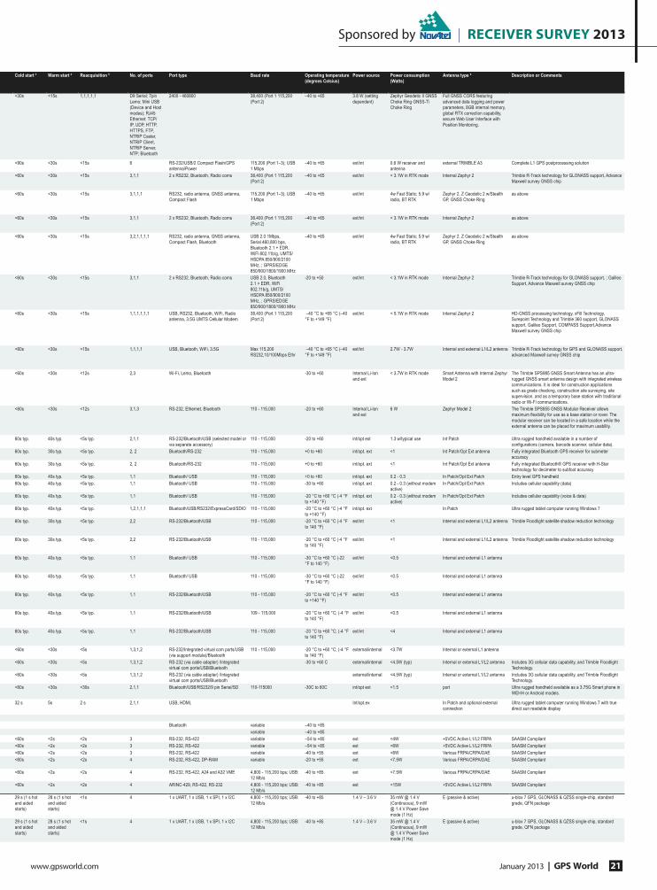
Sponsored by | receiver survey 2013
www.gpsworld.com January 2013 | GPS World 21
Cold start 3 Warm start 4 Reacquisition 5 No. of ports Port type Baud rate Operating temperature
(degrees Celsius)
Power source Power consumption
(Watts)
Antenna type 6 Description or Comments
<30s <15s 1,1,1,1,1 D9 Serial; 7pin
Lemo; Mini USB
(Device and Host
modes); RJ45
Ethernet: TCP/
IP, UDP, HTTP,
HTTPS, FTP,
NTRIP Caster,
NTRIP Client,
NTRIP Server,
NTP; Bluetooth
2400 - 460800 38,400 (Port 1 115,200
(Port 2)
–40 to +65 3.8 W (setting
dependent)
Zephyr Geodetic II GNSS
Choke Ring GNSS-Ti
Choke Ring
Full GNSS CORS featuring
advanced data logging and power
parameters, 8GB internal memory,
global RTX correction capability,
secure Web User Interface with
Position Monitoring.
<90s <30s <15s 6 RS-232/USB/2 Compact Flash/GPS
antenna/Power
115,200 (Port 1–3); USB
1 Mbps
–40 to +65 ext/int 0.6 W receiver and
antenna
external TRIMBLE A3 Complete L1 GPS postprocessing solution
<60s <30s <15s 3,1,1 2 x RS232, Bluetooth, Radio coms 38,400 (Port 1 115,200
(Port 2)
–40 to +65 ext/int < 3.1W in RTK mode Internal Zephyr 2 Trimble R-Track technology for GLONASS support, Advance
Maxwell survey GNSS chip
<60s <30s <15s 3,1,1,1 RS232, radio antenna, GNSS antenna,
Compact Flash
115,200 (Port 1–3); USB
1 Mbps
–40 to +65 ext/int 4w Fast Static; 5.9 w/
radio, BT RTK
Zephyr 2, Z Geodetic 2 w/Stealth
GP, GNSS Choke Ring
as above
<60s <30s <15s 3,1,1 2 x RS232, Bluetooth, Radio coms 38,400 (Port 1 115,200
(Port 2)
–40 to +65 ext/int < 3.1W in RTK mode Internal Zephyr 2 as above
<60s <30s <15s 3,2,1,1,1,1 RS232, radio antenna, GNSS antenna,
Compact Flash, Bluetooth
USB 2.0 1Mbps,
Serial 460,800 bps,
Bluetooth 2.1 + EDR,
WiFi 802.11b/g, UMTS/
HSDPA 850/900/2100
MHz, ; GPRS/EDGE
850/900/1800/1900 MHz
–40 to +65 ext/int 4w Fast Static; 5.9 w/
radio, BT RTK
Zephyr 2, Z Geodetic 2 w/Stealth
GP, GNSS Choke Ring
as above
<60s <30s <15s 3,1,1 2 x RS232, Bluetooth, Radio coms USB 2.0, Bluetooth
2.1 + EDR, WiFi
802.11b/g, UMTS/
HSDPA 850/900/2100
MHz, ; GPRS/EDGE
850/900/1800/1900 MHz
-20 to +50 ext/int < 3.1W in RTK mode Internal Zephyr 2 Trimble R-Track technology for GLONASS support, ; Galileo
Support, Advance Maxwell survey GNSS chip
<60s <30s <15s 1,1,1,1,1,1 USB, RS232, Bluetooth, WiFi, Radio
antenna, 3.5G UMTS Cellular Modem
38,400 (Port 1 115,200
(Port 2)
–40 °C to +65 °C (–40
°F to +149 °F)
ext/int < 5.1W in RTK mode Internal Zephyr 2 HD-GNSS processing technology, xFill Technology,
Surepoint Technology and Trimble 360 support, GLONASS
support, Galileo Support, COMPASS Support,Advance
Maxwell survey GNSS chip
<60s <30s <15s 1,1,1,1 USB, Bluetooth, WiFi, 3.5G Max 115,200
RS232,10/100Mbps Ethr
–40 °C to +65 °C (–40
°F to +149 °F)
ext/int 2.7W - 3.7W Internal and external L1/L2 antenna Trimble R-Track technology for GPS and GLONASS support,
advanced Maxwell survey GNSS chip
<60s <30s <12s 2,3 Wi-Fi, Lemo, Bluetooth -30 to +60 Internal Li-Ion
and ext
< 3.7W in RTK mode Smart Antenna with Internal Zephyr
Model 2
The Trimble SPS985 GNSS Smart Antenna has an ultra-
rugged GNSS smart antenna design with integrated wireless
communications. It is ideal for construction applications
such as grade checking, construction site surveying, site
supervision, and as a temporary base station with traditional
radio or Wi-Fi communications.
<60s <30s <12s 3,1,3 RS-232, Ethernet, Bluetooth 110 - 115,000 -20 to +60 Internal Li-Ion
and ext
6 W Zephyr Model 2 The Trimble SPS855 GNSS Modular Receiver allows
maximum Àexibility for use as a base station or rover. The
modular receiver can be located in a safe location while the
external antenna can be placed for maximum usability.
60s typ. 40s typ. <5s typ. 2,1,1 RS-232/Bluetooth/USB (selected model or
via separate accessory)
110 - 115,000 -20 to +60 int/opt ext 1.3 w/typical use Int Patch Ultra rugged handheld available in a number of
con¿gurations (camera, barcode scanner, cellular data).
60s typ. 30s typ. <5s typ. 2, 2 Bluetooth/RS-232 110 - 115,000 +0 to +60 int/opt. ext <1 Int Patch/Opt Ext antenna Fully integrated Bluetooth GPS receiver for submeter
accuracy
60s typ. 30s typ. <5s typ. 2, 2 Bluetooth/RS-232 110 - 115,000 +0 to +60 int/opt. ext <1 Int Patch/Opt Ext antenna Fully integrated Bluetooth® GPS receiver with H-Star
technology for decimeter to subfoot accuracy
60s typ. 40s typ. <5s typ. 1,1 Bluetooth/ USB 110 - 115,000 +0 to +60 int/opt. ext 0.2 - 0.3 In Patch/Opt Ext Patch Entry level GPS handheld
60s typ. 40s typ. <5s typ. 1,1 Bluetooth/ USB 110 - 115,000 -30 to +60 int/opt. ext 0.2 - 0.3 (without modem
active)
In Patch/Opt Ext Patch Includes cellular capability (data)
60s typ. 40s typ. <5s typ. 1,1 Bluetooth/ USB 110 - 115,000 -20 °C to +60 °C (-4 °F
to +140 °F)
int/opt. ext 0.2 - 0.3 (without modem
active)
In Patch/Opt Ext Patch Includes cellular capability (voice & data)
60s typ. 40s typ. <5s typ. 1,2,1,1,1 Bluetooth/USB/RS232/ExpressCard/SDIO 110 - 115,000 -20 °C to +60 °C (-4 °F
to +140 °F)
int/opt. ext In Patch Ultra rugged tablet computer running Windows 7
60s typ. 30s typ. <5s typ. 2,2 RS-232/Bluetooth/USB 110 - 115,000 -20 °C to +60 °C (-4 °F
to 140 °F)
ext/int <1 Internal and external L1/L2 antenna Trimble Floodlight satellite shadow reduction technology
60s typ. 30s typ. <5s typ. 2,2 RS-232/Bluetooth/USB 110 - 115,000 -20 °C to +60 °C (-4 °F
to 140 °F)
ext/int <1 Internal and external L1/L2 antenna Trimble Floodlight satellite shadow reduction technology
60s typ. 40s typ. <5s typ. 1,1 Bluetooth/ USB 110 - 115,000 -30 °C to +60 °C (-22
°F to 140 °F)
ext/int <0.5 Internal and external L1 antenna
60s typ. 40s typ. <5s typ. 1,1 Bluetooth/ USB 110 - 115,000 -30 °C to +60 °C (-22
°F to 140 °F)
ext/int <0.5 Internal and external L1 antenna
60s typ. 40s typ. <5s typ. 1,1 RS-232/Bluetooth/USB 110 - 115,000 -20 °C to +60 °C (-4 °F
to +140 °F)
ext/int <0.5 Internal and external L1 antenna
60s typ. 40s typ. <5s typ. 1,1 RS-232/Bluetooth/USB 109 - 115,000 -20 °C to +60 °C; (-4 °F
to 140 °F)
ext/int <0.5 Internal and external L1 antenna
60s typ. 40s typ. <5s typ. 1,1 RS-232/Bluetooth/USB 110 - 115,000 -20 °C to +60 °C; (-4 °F
to 140 °F)
ext/int <4 Internal and external L1 antenna
<60s <30s <5s 1,3,1,2 RS-232/Integrated virtual com ports/USB
(via support module)/Bluetooth
110 - 115,000 -20 °C to +60 °C; (-4 °F
to 140 °F)
external/internal <3.7W Internal or external L1 antenna
<60s <30s <5s 1,3,1,2 RS-232 (via cable adapter) /Integrated
virtual com ports/USB/Bluetooth
-30 to +60 C external/internal <4.5W (typ) Internal or external L1/L2 antenna Includes 3G cellular data capability, and Trimble Floodlight
Technology.
<60s <30s <5s 1,3,1,2 RS-232 (via cable adapter) /Integrated
virtual com ports/USB/Bluetooth
external/internal <4.5W (typ) Internal or external L1/L2 antenna Includes 3G cellular data capability, and Trimble Floodlight
Technology.
<60s <30s <30s 2,1,1 Bluetooth/USB/RS232/9 pin Serial/SD 110-115000 -30C to 60C int/opt ext <1.5 port Ultra rugged handheld available as a 3.75G Smart phone in
WEHH or Android models.
32 s 5s 2 s 2,1,1 USB, HDMI, Int/opt.ex In Patch and optional external
connection
Ultra rugged tablet computer running Windows 7 with true
direct sun readable display
Bluetooth variable –40 to +85
variable –40 to +85
<60s <2s <2s 3 RS-232, RS-422 variable –54 to +85 ext <4W +5VDC Active L1/L2 FRPA SAASM Compliant
<60s <2s <2s 3 RS-232, RS-422 variable –54 to +85 ext <6W +5VDC Active L1/L2 FRPA SAASM Compliant
<60s <2s <2s 3 RS-232, RS-422 variable -40 to +55 ext <6W Various FRPA/CRPA/DAE SAASM Compliant
<60s <2s <2s 4 RS-232, RS-422, DP-RAM variable -20 to +55 ext <7.5W Various FRPA/CRPA/DAE SAASM Compliant
<60s <2s <2s 4 RS-232, RS-422, A24 and A32 VME 4,800 - 115,200 bps; USB:
12 Mb/s
-40 to +85 ext <7.5W Various FRPA/CRPA/DAE SAASM Compliant
<60s <2s <2s 4 ARINC-429, RS-422, RS-232 4,800 - 115,200 bps; USB:
12 Mb/s
-40 to +85 ext <15W +5VDC Active L1/L2 FRPA SAASM Compliant
29 s (1 s hot
and aided
starts)
28 s (1 s hot
and aided
starts)
<1s 4 1 x UART, 1 x USB, 1 x SPI, 1 x I2C 4,800 - 115,200 bps; USB:
12 Mb/s
-40 to +85 1.4 V – 3.6 V 35 mW @ 1.4 V
(Continuous), 9 mW
@ 1.4 V Power Save
mode (1 Hz)
E (passive & active) u-blox 7 GPS, GLONASS & QZSS single-chip, standard
grade, QFN package
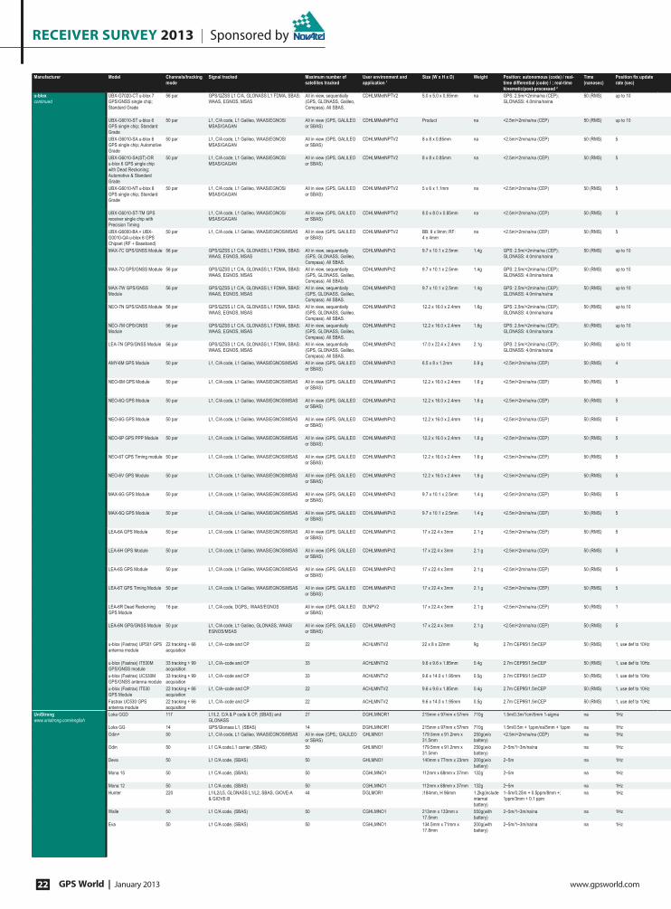
receiver survey 2013 | Sponsored by
GPS World | January 2013 www.gpsworld.com22
Manufacturer Model Channels/tracking
mode
Signal tracked Maximum number of
satellites tracked
User environment and
application 1
Size (W x H x D) Weight Position: autonomous (code) / real-
time differential (code) / ; real-time
kinematic/post-processed 2
Time
(nanosec)
Position Àx update
rate (sec)
u-blox
continued
UBX-G7020-CT u-blox 7
GPS/GNSS single chip;
Standard Grade
56 par GPS/QZSS L1 C/A, GLONASS L1 FDMA, SBAS:
WAAS, EGNOS, MSAS
All in view, sequentially
(GPS, GLONASS, Galileo,
Compass). All SBAS.
CDHLMMetNPTV2 5.0 x 5.0 x 0.55mm na GPS: 2.5m/<2m/na/na (CEP);
GLONASS: 4.0m/na/na/na
50 (RMS) up to 10
UBX-G6010-ST u-blox 6
GPS single chip; Standard
Grade
50 par L1, C/A code, L1 Galileo, WAAS/EGNOS/
MSAS/GAGAN
All in view (GPS, GALILEO
or SBAS)
CDHLMMetNPTV2 Product na <2.5m/<2m/na/na (CEP) 50 (RMS) up to 10
UBX-G6010-SA u-blox 6
GPS single chip; Automotive
Grade
50 par L1, C/A code, L1 Galileo, WAAS/EGNOS/
MSAS/GAGAN
All in view (GPS, GALILEO
or SBAS)
CDHLMMetNPTV2 8 x 8 x 0.85mm na <2.5m/<2m/na/na (CEP) 50 (RMS) 5
UBX-G6010-SA(ST)-DR
u-blox 6 GPS single chip
with Dead Reckoning;
Automotive & Standard
Grade
50 par L1, C/A code, L1 Galileo, WAAS/EGNOS/
MSAS/GAGAN
All in view (GPS, GALILEO
or SBAS)
CDHLMMetNPTV2 8 x 8 x 0.85mm na <2.5m/<2m/na/na (CEP) 50 (RMS) 5
UBX-G6010-NT u-blox 6
GPS single chip; Standard
Grade
50 par L1, C/A code, L1 Galileo, WAAS/EGNOS/
MSAS/GAGAN
All in view (GPS, GALILEO
or SBAS)
CDHLMMetNPTV2 5 x 6 x 1.1mm na <2.5m/<2m/na/na (CEP) 50 (RMS) 5
UBX-G6010-ST-TM GPS
receiver single chip with
Precision Timing
L1, C/A code, L1 Galileo, WAAS/EGNOS/
MSAS/GAGAN
All in view (GPS, GALILEO
or SBAS)
CDHLMMetNPTV2 8.0 x 8.0 x 0.85mm na <2.5m/<2m/na/na (CEP) 50 (RMS) 5
UBX-G6000-BA + UBX-
G0010-QA u-blox 6 GPS
Chipset (RF + Baseband)
50 par L1, C/A code, L1 Galileo, WAAS/EGNOS/MSAS All in view (GPS, GALILEO
or SBAS)
CDHLMMetNPTV2 BB: 9 x 9mm; RF:
4 x 4mm
na <2.5m/<2m/na/na (CEP) 50 (RMS) 5
MAX-7C GPS/GNSS Module 56 par GPS/QZSS L1 C/A, GLONASS L1 FDMA, SBAS:
WAAS, EGNOS, MSAS
All in view, sequentially
(GPS, GLONASS, Galileo,
Compass). All SBAS.
CDHLMMetNPV2 9.7 x 10.1 x 2.5mm 1.4g GPS: 2.5m/<2m/na/na (CEP);
GLONASS: 4.0m/na/na/na
50 (RMS) up to 10
MAX-7Q GPS/GNSS Module 56 par GPS/QZSS L1 C/A, GLONASS L1 FDMA, SBAS:
WAAS, EGNOS, MSAS
All in view, sequentially
(GPS, GLONASS, Galileo,
Compass). All SBAS.
CDHLMMetNPV2 9.7 x 10.1 x 2.5mm 1.4g GPS: 2.5m/<2m/na/na (CEP);
GLONASS: 4.0m/na/na/na
50 (RMS) up to 10
MAX-7W GPS/GNSS
Module
56 par GPS/QZSS L1 C/A, GLONASS L1 FDMA, SBAS:
WAAS, EGNOS, MSAS
All in view, sequentially
(GPS, GLONASS, Galileo,
Compass). All SBAS.
CDHLMMetNPV2 9.7 x 10.1 x 2.5mm 1.4g GPS: 2.5m/<2m/na/na (CEP);
GLONASS: 4.0m/na/na/na
50 (RMS) up to 10
NEO-7N GPS/GNSS Module 56 par GPS/QZSS L1 C/A, GLONASS L1 FDMA, SBAS:
WAAS, EGNOS, MSAS
All in view, sequentially
(GPS, GLONASS, Galileo,
Compass). All SBAS.
CDHLMMetNPV2 12.2 x 16.0 x 2.4mm 1.6g GPS: 2.5m/<2m/na/na (CEP);
GLONASS: 4.0m/na/na/na
50 (RMS) up to 10
NEO-7M GPS/GNSS
Module
56 par GPS/QZSS L1 C/A, GLONASS L1 FDMA, SBAS:
WAAS, EGNOS, MSAS
All in view, sequentially
(GPS, GLONASS, Galileo,
Compass). All SBAS.
CDHLMMetNPV2 12.2 x 16.0 x 2.4mm 1.6g GPS: 2.5m/<2m/na/na (CEP);
GLONASS: 4.0m/na/na/na
50 (RMS) up to 10
LEA-7N GPS/GNSS Module 56 par GPS/QZSS L1 C/A, GLONASS L1 FDMA, SBAS:
WAAS, EGNOS, MSAS
All in view, sequentially
(GPS, GLONASS, Galileo,
Compass). All SBAS.
CDHLMMetNPV2 17.0 x 22.4 x 2.4mm 2.1g GPS: 2.5m/<2m/na/na (CEP);
GLONASS: 4.0m/na/na/na
50 (RMS) up to 10
AMY-6M GPS Module 50 par L1, C/A code, L1 Galileo, WAAS/EGNOS/MSAS All in view (GPS, GALILEO
or SBAS)
CDHLMMetNPV2 6.5 x 8 x 1.2mm 0.8 g <2.5m/<2m/na/na (CEP) 50 (RMS) 4
NEO-6M GPS Module 50 par L1, C/A code, L1 Galileo, WAAS/EGNOS/MSAS All in view (GPS, GALILEO
or SBAS)
CDHLMMetNPV2 12.2 x 16.0 x 2.4mm 1.6 g <2.5m/<2m/na/na (CEP) 50 (RMS) 5
NEO-6Q GPS Module 50 par L1, C/A code, L1 Galileo, WAAS/EGNOS/MSAS All in view (GPS, GALILEO
or SBAS)
CDHLMMetNPV2 12.2 x 16.0 x 2.4mm 1.6 g <2.5m/<2m/na/na (CEP) 50 (RMS) 5
NEO-6G GPS Module 50 par L1, C/A code, L1 Galileo, WAAS/EGNOS/MSAS All in view (GPS, GALILEO
or SBAS)
CDHLMMetNPV2 12.2 x 16.0 x 2.4mm 1.6 g <2.5m/<2m/na/na (CEP) 50 (RMS) 5
NEO-6P GPS PPP Module 50 par L1, C/A code, L1 Galileo, WAAS/EGNOS/MSAS All in view (GPS, GALILEO
or SBAS)
CDHLMMetNPV2 12.2 x 16.0 x 2.4mm 1.6 g <2.5m/<2m/na/na (CEP) 50 (RMS) 5
NEO-6T GPS Timing module 50 par L1, C/A code, L1 Galileo, WAAS/EGNOS/MSAS All in view (GPS, GALILEO
or SBAS)
CDHLMMetNPV2 12.2 x 16.0 x 2.4mm 1.6 g <2.5m/<2m/na/na (CEP) 50 (RMS) 5
NEO-6V GPS Module 50 par L1, C/A code, L1 Galileo, WAAS/EGNOS/MSAS All in view (GPS, GALILEO
or SBAS)
CDHLMMetNPV2 12.2 x 16.0 x 2.4mm 1.6 g <2.5m/<2m/na/na (CEP) 50 (RMS) 5
MAX-6G GPS Module 50 par L1, C/A code, L1 Galileo, WAAS/EGNOS/MSAS All in view (GPS, GALILEO
or SBAS)
CDHLMMetNPV2 9.7 x 10.1 x 2.5mm 1.4 g <2.5m/<2m/na/na (CEP) 50 (RMS) 5
MAX-6Q GPS Module 50 par L1, C/A code, L1 Galileo, WAAS/EGNOS/MSAS All in view (GPS, GALILEO
or SBAS)
CDHLMMetNPV2 9.7 x 10.1 x 2.5mm 1.4 g <2.5m/<2m/na/na (CEP) 50 (RMS) 5
LEA-6A GPS Module 50 par L1, C/A code, L1 Galileo, WAAS/EGNOS/MSAS All in view (GPS, GALILEO
or SBAS)
CDHLMMetNPV2 17 x 22.4 x 3mm 2.1 g <2.5m/<2m/na/na (CEP) 50 (RMS) 5
LEA-6H GPS Module 50 par L1, C/A code, L1 Galileo, WAAS/EGNOS/MSAS All in view (GPS, GALILEO
or SBAS)
CDHLMMetNPV2 17 x 22.4 x 3mm 2.1 g <2.5m/<2m/na/na (CEP) 50 (RMS) 5
LEA-6S GPS Module 50 par L1, C/A code, L1 Galileo, WAAS/EGNOS/MSAS All in view (GPS, GALILEO
or SBAS)
CDHLMMetNPV2 17 x 22.4 x 3mm 2.1 g <2.5m/<2m/na/na (CEP) 50 (RMS) 5
LEA-6T GPS Timing Module 50 par L1, C/A code, L1 Galileo, WAAS/EGNOS/MSAS All in view (GPS, GALILEO
or SBAS)
CDHLMMetNPV2 17 x 22.4 x 3mm 2.1 g <2.5m/<2m/na/na (CEP) 50 (RMS) 5
LEA-6R Dead Reckoning
GPS Module
16 par. L1, C/A code, DGPS,; WAAS/EGNOS All in view (GPS, GALILEO
or SBAS)
DLNPV2 17 x 22.4 x 3mm 2.1 g <2.5m/<2m/na/na (CEP) 50 (RMS) 1
LEA-6N GPS/GNSS Module 50 par L1, C/A code, L1 Galileo, GLONASS, WAAS/
EGNOS/MSAS
All in view (GPS, GALILEO
or SBAS)
CDHLMMetNPV2 17 x 22.4 x 3mm 2.1 g <2.5m/<2m/na/na (CEP) 50 (RMS) 5
u-blox (Fastrax) UP501 GPS
antenna module
22 tracking + 66
acquisition
L1, C/A–code and CP 22 ACHLMNTV2 22 x 8 x 22mm 9g 2.7m CEP95/1.5mCEP 50 (RMS) 1, use def to 10Hz
u-blox (Fastrax) IT530M
GPS/GNSS module
33 tracking + 99
acquisition
L1, C/A–code and CP 33 ACHLMNTV2 9.6 x 9.6 x 1.85mm 0.4g 2.7m CEP95/1.5mCEP 50 (RMS) 1, use def to 10Hz
u-blox (Fastrax) UC530M
GPS/GNSS antenna module
33 tracking + 99
acquisition
L1, C/A–code and CP 33 ACHLMNTV2 9.6 x 14.0 x 1.95mm 0.5g 2.7m CEP95/1.5mCEP 50 (RMS) 1, use def to 10Hz
u-blox (Fastrax) IT530
GPS Module
22 tracking + 66
acquisition
L1, C/A–code and CP 22 ACHLMNTV2 9.6 x 9.6 x 1.85mm 0.4g 2.7m CEP95/1.5mCEP 50 (RMS) 1, use def to 10Hz
Fastrax UC530 GPS
antenna module
22 tracking + 66
acquisition
L1, C/A–code and CP 22 ACHLMNTV2 9.6 x 14.0 x 1.95mm 0.5g 2.7m CEP95/1.5mCEP 50 (RMS) 1, use def to 10Hz
UniStrong
www.unistrong.com/english
Loka GGD 117 L1/L2, C/A & P code & CP, (SBAS) and
GLONASS
27 DGHLMNOR1 215mm x 97mm x 57mm 710g 1.5m/0.3m/1cm/5mm 1-sigma na 1Hz
Loka GG 14 GPS/Glonass L1, (SBAS) 14 DGHLMNOR1 215mm x 97mm x 57mm 710g 1.5m/0.5m + 1ppm/na/5mm + 1ppm na 1Hz
Odin+ 50 L1, C/A code, L1 Galileo, WAAS/EGNOS/MSAS All in view (GPS,; GALILEO
or SBAS)
GHLMNO1 179.5mm x 91.2mm x
31.5mm
250g(w/o
battery)
<2.5m/<2m/na/na (CEP) na 1Hz
Odin 50 L1 C/A code,L1 carrier, (SBAS) 50 GHLMNO1 179.5mm x 91.2mm x
31.5mm
250g(w/o
battery)
2~5m/1~3m/na/na na 1Hz
Deva 50 L1 C/A code, (SBAS) 50 GHLMNO1 140mm x 77mm x 23mm 200g(w/o
battery)
2~5m na 1Hz
Mona 15 50 L1 C/A code, (SBAS) 50 CGHLMNO1 112mm x 68mm x 37mm 132g 2~5m na 1Hz
Mona 12 50 L1 C/A code, (SBAS) 50 CGHLMNO1 112mm x 68mm x 37mm 132g 2~5m na 1Hz
Hunter 220 L1/L2/L5, GLONASS L1/L2, SBAS, GIOVE-A
& GIOVE-B
44 DGLMOR1 ∮184mm, H 96mm 1.2kg(include
internal
battery)
1–5m/0.25m + 0.5ppm/8mm +;
1ppm/3mm + 0.1 ppm
na 1Hz
Walle 50 L1 C/A code, (SBAS) 50 CGHLMNO1 213mm x 133mm x
17.5mm
550g(with
battery)
2~5m/1~3m/na/na na 1Hz
Eva 50 L1 C/A code, (SBAS) 50 CGHLMNO1 134.5mm x 71mm x
17.8mm
200g(with
battery)
2~5m/1~3m/na/na na 1Hz
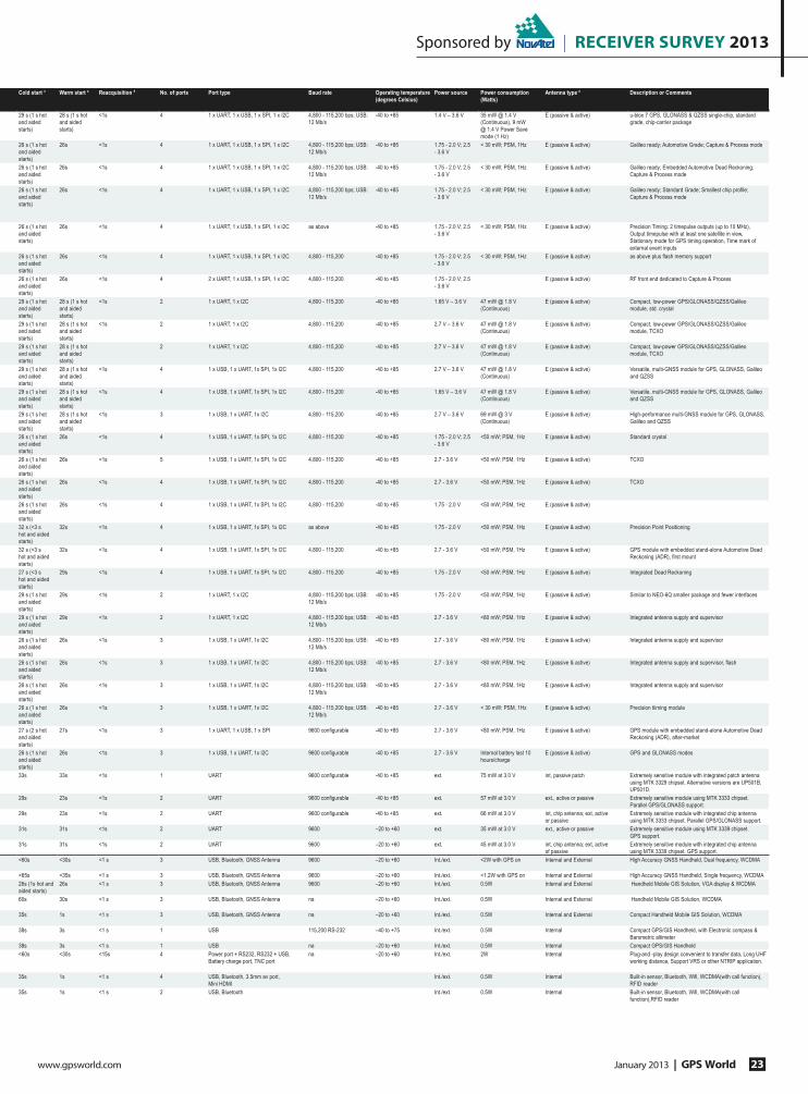
Sponsored by | receiver survey 2013
www.gpsworld.com January 2013 | GPS World 23
Cold start 3 Warm start 4 Reacquisition 5 No. of ports Port type Baud rate Operating temperature
(degrees Celsius)
Power source Power consumption
(Watts)
Antenna type 6 Description or Comments
29 s (1 s hot
and aided
starts)
28 s (1 s hot
and aided
starts)
<1s 4 1 x UART, 1 x USB, 1 x SPI, 1 x I2C 4,800 - 115,200 bps; USB:
12 Mb/s
-40 to +85 1.4 V – 3.6 V 35 mW @ 1.4 V
(Continuous), 9 mW
@ 1.4 V Power Save
mode (1 Hz)
E (passive & active) u-blox 7 GPS, GLONASS & QZSS single-chip, standard
grade, chip-carrier package
26 s (1 s hot
and aided
starts)
26s <1s 4 1 x UART, 1 x USB, 1 x SPI, 1 x I2C 4,800 - 115,200 bps; USB:
12 Mb/s
-40 to +85 1.75 - 2.0 V; 2.5
- 3.6 V
< 30 mW; PSM, 1Hz E (passive & active) Galileo ready; Automotive Grade; Capture & Process mode
26 s (1 s hot
and aided
starts)
26s <1s 4 1 x UART, 1 x USB, 1 x SPI, 1 x I2C 4,800 - 115,200 bps; USB:
12 Mb/s
-40 to +85 1.75 - 2.0 V; 2.5
- 3.6 V
< 30 mW; PSM, 1Hz E (passive & active) Galileo ready; Embedded Automotive Dead Reckoning;
Capture & Process mode
26 s (1 s hot
and aided
starts)
26s <1s 4 1 x UART, 1 x USB, 1 x SPI, 1 x I2C 4,800 - 115,200 bps; USB:
12 Mb/s
-40 to +85 1.75 - 2.0 V; 2.5
- 3.6 V
< 30 mW; PSM, 1Hz E (passive & active) Galileo ready; Standard Grade; Smallest chip pro¿le;
Capture & Process mode
26 s (1 s hot
and aided
starts)
26s <1s 4 1 x UART, 1 x USB, 1 x SPI, 1 x I2C as above -40 to +85 1.75 - 2.0 V; 2.5
- 3.6 V
< 30 mW; PSM, 1Hz E (passive & active) Precision Timing: 2 timepulse outputs (up to 10 MHz),
Output timepulse with at least one satellite in view,
Stationary mode for GPS timing operation, Time mark of
external event inputs
26 s (1 s hot
and aided
starts)
26s <1s 4 1 x UART, 1 x USB, 1 x SPI, 1 x I2C 4,800 - 115,200 -40 to +85 1.75 - 2.0 V; 2.5
- 3.6 V
< 30 mW; PSM, 1Hz E (passive & active) as above plus Àash memory support
26 s (1 s hot
and aided
starts)
26s <1s 4 2 x UART, 1 x USB, 1 x SPI, 1 x I2C 4,800 - 115,200 -40 to +85 1.75 - 2.0 V; 2.5
- 3.6 V
E (passive & active) RF front end dedicated to Capture & Process
29 s (1 s hot
and aided
starts)
28 s (1 s hot
and aided
starts)
<1s 2 1 x UART, 1 x I2C 4,800 - 115,200 -40 to +85 1.65 V – 3.6 V 47 mW @ 1.8 V
(Continuous)
E (passive & active) Compact, low-power GPS/GLONASS/QZSS/Galileo
module, std. crystal
29 s (1 s hot
and aided
starts)
28 s (1 s hot
and aided
starts)
<1s 2 1 x UART, 1 x I2C 4,800 - 115,200 -40 to +85 2.7 V – 3.6 V 47 mW @ 1.8 V
(Continuous)
E (passive & active) Compact, low-power GPS/GLONASS/QZSS/Galileo
module, TCXO
29 s (1 s hot
and aided
starts)
28 s (1 s hot
and aided
starts)
2 1 x UART, 1 x I2C 4,800 - 115,200 -40 to +85 2.7 V – 3.6 V 47 mW @ 1.8 V
(Continuous)
E (passive & active) Compact, low-power GPS/GLONASS/QZSS/Galileo
module, TCXO
29 s (1 s hot
and aided
starts)
28 s (1 s hot
and aided
starts)
<1s 4 1 x USB, 1 x UART, 1x SPI, 1x I2C 4,800 - 115,200 -40 to +85 2.7 V – 3.6 V 47 mW @ 1.8 V
(Continuous)
E (passive & active) Versatile, multi-GNSS module for GPS, GLONASS, Galileo
and QZSS
29 s (1 s hot
and aided
starts)
28 s (1 s hot
and aided
starts)
<1s 4 1 x USB, 1 x UART, 1x SPI, 1x I2C 4,800 - 115,200 -40 to +85 1.65 V – 3.6 V 47 mW @ 1.8 V
(Continuous)
E (passive & active) Versatile, multi-GNSS module for GPS, GLONASS, Galileo
and QZSS
29 s (1 s hot
and aided
starts)
28 s (1 s hot
and aided
starts)
<1s 3 1 x USB, 1 x UART, 1x I2C 4,800 - 115,200 -40 to +85 2.7 V – 3.6 V 69 mW @ 3 V
(Continuous)
E (passive & active) High-performance multi-GNSS module for GPS, GLONASS,
Galileo and QZSS
26 s (1 s hot
and aided
starts)
26s <1s 4 1 x USB, 1 x UART, 1x SPI, 1x I2C 4,800 - 115,200 -40 to +85 1.75 - 2.0 V; 2.5
- 3.6 V
<50 mW; PSM, 1Hz E (passive & active) Standard crystal
26 s (1 s hot
and aided
starts)
26s <1s 5 1 x USB, 1 x UART, 1x SPI, 1x I2C 4,800 - 115,200 -40 to +85 2.7 - 3.6 V <50 mW; PSM, 1Hz E (passive & active) TCXO
26 s (1 s hot
and aided
starts)
26s <1s 4 1 x USB, 1 x UART, 1x SPI, 1x I2C 4,800 - 115,200 -40 to +85 2.7 - 3.6 V <50 mW; PSM, 1Hz E (passive & active) TCXO
26 s (1 s hot
and aided
starts)
26s <1s 4 1 x USB, 1 x UART, 1x SPI, 1x I2C 4,800 - 115,200 -40 to +85 1.75 - 2.0 V <50 mW; PSM, 1Hz E (passive & active)
32 s (<3 s
hot and aided
starts)
32s <1s 4 1 x USB, 1 x UART, 1x SPI, 1x I2C as above -40 to +85 1.75 - 2.0 V <50 mW; PSM, 1Hz E (passive & active) Precision Point Positioning
32 s (<3 s
hot and aided
starts)
32s <1s 4 1 x USB, 1 x UART, 1x SPI, 1x I2C 4,800 - 115,200 -40 to +85 2.7 - 3.6 V <50 mW; PSM, 1Hz E (passive & active) GPS module with embedded stand-alone Automotive Dead
Reckoning (ADR), ¿rst mount
27 s (<3 s
hot and aided
starts)
29s <1s 4 1 x USB, 1 x UART, 1x SPI, 1x I2C 4,800 - 115,200 -40 to +85 1.75 - 2.0 V <50 mW; PSM, 1Hz E (passive & active) Integrated Dead Reckoning
29 s (1 s hot
and aided
starts)
29s <1s 2 1 x UART, 1 x I2C 4,800 - 115,200 bps; USB:
12 Mb/s
-40 to +85 1.75 - 2.0 V <50 mW; PSM, 1Hz E (passive & active) Similar to NEO-6Q smaller package and fewer interfaces
29 s (1 s hot
and aided
starts)
29s <1s 2 1 x UART, 1 x I2C 4,800 - 115,200 bps; USB:
12 Mb/s
-40 to +85 2.7 - 3.6 V <80 mW; PSM, 1Hz E (passive & active) Integrated antenna supply and supervisor
26 s (1 s hot
and aided
starts)
26s <1s 3 1 x USB, 1 x UART, 1x I2C 4,800 - 115,200 bps; USB:
12 Mb/s
-40 to +85 2.7 - 3.6 V <80 mW; PSM, 1Hz E (passive & active) Integrated antenna supply and supervisor
26 s (1 s hot
and aided
starts)
26s <1s 3 1 x USB, 1 x UART, 1x I2C 4,800 - 115,200 bps; USB:
12 Mb/s
-40 to +85 2.7 - 3.6 V <80 mW; PSM, 1Hz E (passive & active) Integrated antenna supply and supervisor, Àash
26 s (1 s hot
and aided
starts)
26s <1s 3 1 x USB, 1 x UART, 1x I2C 4,800 - 115,200 bps; USB:
12 Mb/s
-40 to +85 2.7 - 3.6 V <80 mW; PSM, 1Hz E (passive & active) Integrated antenna supply and supervisor
26 s (1 s hot
and aided
starts)
26s <1s 3 1 x USB, 1 x UART, 1x I2C 4,800 - 115,200 bps; USB:
12 Mb/s
-40 to +85 2.7 - 3.6 V < 30 mW; PSM, 1Hz E (passive & active) Precision tiiming module
27 s (2 s hot
and aided
starts)
27s <1s 3 1 x UART, 1 x USB, 1 x SPI 9600 con¿gurable -40 to +85 2.7 - 3.6 V <80 mW; PSM, 1Hz E (passive & active) GPS module with embedded stand-alone Automotive Dead
Reckoning (ADR), after-market
26 s (1 s hot
and aided
starts)
26s <1s 3 1 x USB, 1 x UART, 1x I2C 9600 con¿gurable -40 to +85 2.7 - 3.6 V Internal battery last 10
hours/charge
E (passive & active) GPS and GLONASS modes
33s 33s <1s 1 UART 9600 con¿gurable -40 to +85 ext. 75 mW at 3.0 V int, passive patch Extremely sensitive module with integrated patch antenna
using MTK 3329 chipset. Alternative versions are UP501B,
UP501D.
29s 23s <1s 2 UART 9600 con¿gurable -40 to +85 ext. 57 mW at 3.0 V ext., active or passive Extremely sensitive module using MTK 3333 chipset.
Parallel GPS/GLONASS support.
29s 23s <1s 2 UART 9600 con¿gurable -40 to +85 ext. 66 mW at 3.0 V int, chip antenna; ext, active
or passive
Extremely sensitive module with integrated chip antenna
using MTK 3333 chipset. Parallel GPS/GLONASS support.
31s 31s <1s 2 UART 9600 –20 to +60 ext. 35 mW at 3.0 V ext., active or passive Extremely sensitive module using MTK 3339 chipset.
GPS support.
31s 31s <1s 2 UART 9600 –20 to +60 ext. 45 mW at 3.0 V int, chip antenna; ext, active
of passive
Extremely sensitive module with integrated chip antenna
using MTK 3339 chipset. GPS support.
<60s <30s <1 s 3 USB, Bluetooth, GNSS Antenna 9600 –20 to +60 Int./ext. <2W with GPS on Internal and External High Accuracy GNSS Handheld, Dual frequency, WCDMA
<65s <35s <1 s 3 USB, Bluetooth, GNSS Antenna 9600 –20 to +60 Int./ext. <1.2W with GPS on Internal and External High Accuracy GNSS Handheld, Single frequency, WCDMA
26s (1s hot and
aided starts)
26s <1 s 3 USB, Bluetooth, GNSS Antenna 9600 –20 to +60 Int./ext. 0.5W Internal and External Handheld Mobile GIS Solution, VGA display & WCDMA
60s 30s <1 s 3 USB, Bluetooth, GNSS Antenna na –20 to +60 Int./ext. 0.5W Internal and External Handheld Mobile GIS Solution, WCDMA
35s 1s <1 s 3 USB, Bluetooth, GNSS Antenna na –20 to +60 Int./ext. 0.5W Internal and External Compact Handheld Mobile GIS Solution, WCDMA
38s 3s <1 s 1 USB 115,200 RS-232 –40 to +75 Int./ext. 0.5W Internal Compact GPS/GIS Handheld, with Electronic compass &
Barometric altimeter
38s 3s <1 s 1 USB na –20 to +60 Int./ext. 0.5W Internal Compact GPS/GIS Handheld
<60s <30s <15s 4 Power port + RS232, RS232 + USB,
Battery charge port, TNC port
na –20 to +60 Int./ext. 2W Internal Plug-and -play design convenient to transfer data, Long UHF
working distance, Support VRS or other NTRIP application.
35s 1s <1 s 4 USB, Bluetooth, 3.5mm av port,
Mini HDMI
Int./ext. 0.5W Internal Built-in sensor, Bluetooth, Wi¿, WCDMA(with call function),
RFID reader
35s 1s <1 s 2 USB, Bluetooth Int./ext. 0.5W Internal Built-in sensor, Bluetooth, Wi¿, WCDMA(with call
function),RFID reader

SPAN®. Your positioning superhero.
SPAN is the world’s most reliable OEM GNSS/INS technology, with the ability to provide continuous
position, velocity and attitude. So an unprecedented mission—like landing an unmanned helicopter
on a moving marine vessel—no longer stands in the way of success. Imagine how this kind of
sensory superpower will help you rule in your world. As always, we’ll keep your identity secret.
To find out more, visit novatel.com/span or call you know who.
Integrate success into your .
MAKE EXACT POSITIONING A SIXTH SENSE
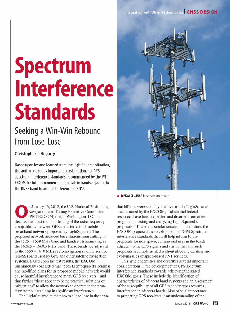
www.gpsworld.com January 2013 | GPS World 59
On January 13, 2012, the U.S. National Positioning,
Navigation, and Timing Executive Committee
(PNT EXCOM) met in Washington, D.C., to
discuss the latest round of testing of the radiofrequency
compatibility between GPS and a terrestrial mobile
broadband network proposed by LightSquared. The
proposed network included base stations transmitting in
the 1525 – 1559 MHz band and handsets transmitting in
the 1626.5 – 1660.5 MHz band. These bands are adjacent
to the 1559 – 1610 MHz radionavigation satellite service
(RNSS) band used by GPS and other satellite navigation
systems. Based upon the test results, the EXCOM
unanimously concluded that “both LightSquared’s original
and modified plans for its proposed mobile network would
cause harmful interference to many GPS receivers,” and
that further “there appear to be no practical solutions or
mitigations” to allow the network to operate in the near-
term without resulting in significant interference.
The LightSquared outcome was a lose-lose in the sense
that billions were spent by the investors in LightSquared
and, as noted by the EXCOM, “substantial federal
resources have been expended and diverted from other
programs in testing and analyzing LightSquared’s
proposals.” To avoid a similar situation in the future, the
EXCOM proposed the development of “GPS Spectrum
interference standards that will help inform future
proposals for non-space, commercial uses in the bands
adjacent to the GPS signals and ensure that any such
proposals are implemented without affecting existing and
evolving uses of space-based PNT services.”
This article identifies and describes several important
considerations in the development of GPS spectrum
interference standards towards achieving the stated
EXCOM goals. These include the identification of
characteristics of adjacent band systems and an assessment
of the susceptibility of all GPS receiver types towards
interference in adjacent bands. Also of vital importance
to protecting GPS receivers is an understanding of the
Spectrum Interference StandardsSeeking a Win-Win Rebound from Lose-Lose
▲ typIcal cellular base-station tower.
Integration with Other Technologies | GNSS deSiGN
Based upon lessons learned from the LightSquared situation, the author identifies important considerations for GPS spectrum interference standards, recommended by the PNT EXCOM for future commercial proposals in bands adjacent to the RNSS band to avoid interference to GNSS.
Christopher J. Hegarty
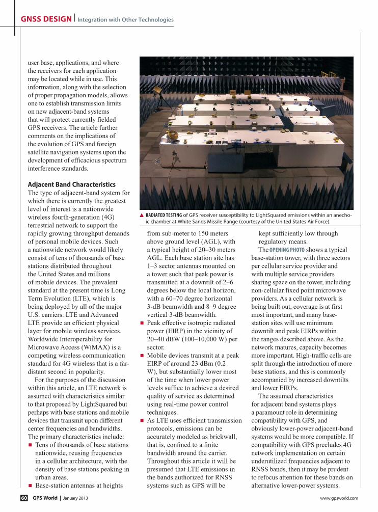
GPS World | January 2013 www.gpsworld.com60
GNSS DESIGN | Integration with Other Technologies
user base, applications, and where
the receivers for each application
may be located while in use. This
information, along with the selection
of proper propagation models, allows
one to establish transmission limits
on new adjacent-band systems
that will protect currently fielded
GPS receivers. The article further
comments on the implications of
the evolution of GPS and foreign
satellite navigation systems upon the
development of efficacious spectrum
interference standards.
Adjacent Band CharacteristicsThe type of adjacent-band system for
which there is currently the greatest
level of interest is a nationwide
wireless fourth-generation (4G)
terrestrial network to support the
rapidly growing throughput demands
of personal mobile devices. Such
a nationwide network would likely
consist of tens of thousands of base
stations distributed throughout
the United States and millions
of mobile devices. The prevalent
standard at the present time is Long
Term Evolution (LTE), which is
being deployed by all of the major
U.S. carriers. LTE and Advanced
LTE provide an ef¿cient physical
layer for mobile wireless services.
Worldwide Interoperability for
Microwave Access (WiMAX) is a
competing wireless communication
standard for 4G wireless that is a far-
distant second in popularity.
For the purposes of the discussion
within this article, an LTE network is
assumed with characteristics similar
to that proposed by LightSquared but
perhaps with base stations and mobile
devices that transmit upon different
center frequencies and bandwidths.
The primary characteristics include:
◾ Tens of thousands of base stations
nationwide, reusing frequencies
in a cellular architecture, with the
density of base stations peaking in
urban areas.
◾ Base-station antennas at heights
from sub-meter to 150 meters
above ground level (AGL), with
a typical height of 20–30 meters
AGL. Each base station site has
1–3 sector antennas mounted on
a tower such that peak power is
transmitted at a downtilt of 2–6
degrees below the local horizon,
with a 60–70 degree horizontal
3-dB beamwidth and 8–9 degree
vertical 3-dB beamwidth.
◾ Peak effective isotropic radiated
power (EIRP) in the vicinity of
20–40 dBW (100–10,000 W) per
sector.
◾ Mobile devices transmit at a peak
EIRP of around 23 dBm (0.2
W), but substantially lower most
of the time when lower power
levels suf¿ce to achieve a desired
quality of service as determined
using real-time power control
techniques.
◾ As LTE uses ef¿cient transmission
protocols, emissions can be
accurately modeled as brickwall,
that is, con¿ned to a ¿nite
bandwidth around the carrier.
Throughout this article it will be
presumed that LTE emissions in
the bands authorized for RNSS
systems such as GPS will be
kept suf¿ciently low through
regulatory means.
The opening photo shows a typical
base-station tower, with three sectors
per cellular service provider and
with multiple service providers
sharing space on the tower, including
non-cellular fixed point microwave
providers. As a cellular network is
being built out, coverage is at first
most important, and many base-
station sites will use minimum
downtilt and peak EIRPs within
the ranges described above. As the
network matures, capacity becomes
more important. High-traffic cells are
split through the introduction of more
base stations, and this is commonly
accompanied by increased downtilts
and lower EIRPs.
The assumed characteristics
for adjacent band systems plays
a paramount role in determining
compatibility with GPS, and
obviously lower-power adjacent-band
systems would be more compatible. If
compatibility with GPS precludes 4G
network implementation on certain
underutilized frequencies adjacent to
RNSS bands, then it may be prudent
to refocus attention for these bands on
alternative lower-power systems.
▲ radiated testing of GPS receiver susceptibility to LightSquared emissions within an anecho-ic chamber at White Sands Missile Range (courtesy of the United States Air Force).

www.gpsworld.com January 2013 | GPS World 61
Integration with Other Technologies | GNSS deSiGN
GPS Receiver SusceptibilityOver the past two years, millions of dollars have been
expended to measure or analyze the susceptibility of
GPS receivers to adjacent band interference as part
of U.S. regulatory proceedings for LightSquared.
Measurements were conducted through both radiated
(see photo) and conducted tests at multiple facilities, as
well as in a live-sky demonstration in Las Vegas. This
section summarizes the ¿ndings for seven categories of
GPS receivers. These categories, which were originally
identi¿ed in the Federal Communications Commission
(FCC)-mandated GPS-LightSquared Technical Working
Group (TWG) formed in February 2011, are: aviation,
cellular, general location/navigation, high-precision,
timing, networks, and space-based receivers.
Aviation. Certi¿ed aviation GPS receivers are one of the
few receiver types for which interference requirements
exist. These requirements take the form of an interference
mask (see Figure 1) that is included in both domestic and
international standards. Certi¿ed aviation GPS receivers
must meet all applicable performance requirements
in the presence of interference levels up to those
indicated in the mask as a function of center frequency.
In Figure 1 and throughout this article, all interference
levels are referred to the output of the GPS receiver
passive-antenna element. Although the mask only
spans 1500–1640 MHz, within applicable domestic and
international standards the curves are de¿ned to extend
over the much wider range of frequencies from 1315 to
2000 MHz.
A handful of aviation GPS receivers were tested against
LightSquared emissions in both conducted and radiated
campaigns. The results indicated that these receivers are
compliant with the mask with potentially some margin.
However, the Federal Aviation Administration (FAA)
noted the following significant limitations of the testing:
◾ Not all receiver performance requirements were tested.
◾ Only a limited number of certi¿ed receivers were
tested, and even those tested were not tested with
every combination of approved equipment (for
example, receiver/antenna pairings).
◾ Tests were not conducted in the environmental
conditions that the equipment was certi¿ed to tolerate
(for example, across the wide range of temperatures
that an airborne active antenna experiences, and
the extreme vibration pro¿le that is experienced by
avionics upon some aircraft).
Due to these limitations, the FAA focused attention upon
the standards rather than the test results for LightSquared
compatibility analyses, and these standards are also
recommended for use in the development of national GPS
interference standards. One finding from the measurements
of aviation receivers that may be useful, however, is that
the devices tested exhibited susceptibilities to out-of-band
interference that were nearly constant as a function of
interference bandwidth. This fact is useful since the out-
of-band interference mask within aviation standards is
only defined for continuous-wave (pure tone) interference,
whereas LightSquared and other potential adjacent-band
systems use signals with bandwidths of 5 MHz or greater.
Cellular. The TWG tested 41 cellular devices supplied
by four U.S. carriers (AT&T, Sprint, US Cellular, and
Verizon) against LightSquared emissions in the late
spring/early summer of 2011. At least one of the 41
devices failed industry standards in the presence of a 5-
or 10-MHz LTE signal centered at 1550 MHz at levels
as low as –55 dBm, and at least one failed for a 10-MHz
LTE signal centered at 1531 MHz at levels as low as
–45 dBm. The worst performing cellular devices were
either not production models or very old devices, and if
the results for these devices are excluded, then the most
susceptible device could tolerate a 10-MHz LTE signal
centered at 1531 MHz at power levels of up to –30 dBm.
Careful retesting took place in the fall of 2011, yielding
a lower maximum susceptibility value of –27 dBm under
the same conditions.
general Location/Navigation. The TWG effort tested 29
general location/navigation devices. In the presence of a
pair of 10-MHz LTE signals centered at 1531 MHz and
1550 MHz, the most susceptible device experienced a
1-dB signal-to-noise ratio (SNR) degradation when each
LTE signal was received at –58.9 dBm. In the presence
of a single 10-MHz LTE signal centered at 1531 MHz,
the most susceptible device experienced a 1-dB SNR
degradation when the interfering signal was received at
–33 dBm.
Much more extensive testing of the effects of a single
LTE signal centered at 1531 MHz on general location/
navigation devices was conducted in the fall of 2011,
▲ Figure 1 Certified aviation receiver interference mask.

GPS World | January 2013 www.gpsworld.com62
GNSS DESIGN | Integration with Other Technologies
evaluating 92 devices. The final report on this campaign
noted that 69 of the 92 devices experienced a 1-dB SNR
decrease or greater when “at an equivalent distance of
greater than 100 meters from the LightSquared simulated
tower.” Since the tower was modeled as transmitting an
EIRP of 62 dBm, the 100-meter separation is equivalent to
a received power level of around –14 dBm. The two most
susceptible devices experienced 1-dB SNR degradations at
received power levels less than –45 dBm.
High Precision, Timing, Networks. The early 2011 TWG
campaign tested 44 high-precision and 13 timing
receivers. 10 percent of the high-precision (timing)
devices experienced a 1-dB or more SNR degradation in
the presence of a 10-MHz LTE signal centered at 1550
MHz at a received power level of –81 dBm (–72 dBm).
With the 10-MHz LTE signal centered at 1531 MHz, this
level increased to –67 dBm (–39 dBm).
The reason that some high-precision GPS receivers are
so sensitive to interference in the 1525–1559 MHz band
is that they were built with wideband radiofrequency
front-ends to intentionally process both GPS and mobile
satellite service (MSS) signals. The latter signals provide
differential GPS corrections supplied by commercial
service providers that lease MSS satellite transponders,
from companies including LightSquared.
Space. Two space-based receivers were tested for
the TWG study. The ¿rst was a current-generation
receiver, and the second a next-generation receiver
under development. The two receivers experienced 1-dB
C/A-code SNR degradation with total interference power
levels of –59 dBm and –82 dBm in the presence of two
5-MHz LTE signals centered at 1528.5 MHz and 1552.7
MHz. For a single 10-MHz LTE signal centered at 1531
MHz, the levels corresponding to a 1-dB C/A-code
SNR degradation increased to –13 dBm and –63 dBm.
The next-generation receiver was more susceptible to
adjacent-band interference because it was developed to
“be reprogrammed in Àight to different frequencies over
the full range of GNSS and augmentation signals.”
Discussion. Although extensive amounts of data were
produced, the LightSquared studies are insuf¿cient by
themselves for the development of GPS interference
standards, since they only assessed the susceptibility
of GPS receivers to interference at the speci¿c carrier
frequencies and with the speci¿c bandwidths proposed
by LightSquared. If GPS interference standards are to
be developed for additional bands, then much more
comprehensive measurements will be necessary.
Interestingly, NTIA in 1998 initiated a GPS receiver
interference susceptibility study, funded by the Department
of Defense (DoD) and conducted by DoD’s Joint Spectrum
Center. One set of curves produced by the study is
shown in Figure 2. This format would be a useful output
of a further measurement campaign. The curves depict
the interference levels needed to produce a 1-dB SNR
degradation to one GPS device as the bandwidth and
center frequency of the interference is varied. The NTIA
curves only extended from GPS L1 (1575.42 MHz) ± 20
MHz. A much wider range would be needed to develop
GPS interference standards as envisioned by the PNT
EXCOM. It may be possible, to minimize testing, to
exclude certain ranges of frequencies corresponding to
bands that stakeholders agree are unlikely to be repurposed
for new (for example, mobile broadband) systems.
Receiver-Transmitter ProximityThe LightSquared studies, with the exception of those
focused on aviation and space applications, spent far less
attention to receiver-transmitter proximity. Minimum
separation distances and the associated geometry are
obviously very important towards determining the
maximum interference level that might be expected for
a given LTE network (or other adjacent band system)
laydown.
Within the TWG, the assumption generally made for
other (non-aviation, non-space) GPS receiver categories
▲ Figure 3 Measurements of received power levels from one experimental LightSquared base station sector in Las Vegas live-sky testing. ▲ Figure 2 Example of NTIA-initiated receiver susceptibility
measurements from 1998.

www.gpsworld.com January 2013 | GPS World 63
Integration with Other Technologies | GNSS deSiGN
was that they could see power levels that were measured
in Las Vegas a couple of meters above the ground from a
live LightSquared tower. Figure 3 shows one set of received
power measurements from Las Vegas. In the figure, the
dots are measured received power levels made by a test
van. The top curve is a prediction of received power based
upon the free-space path-loss model. The bottom curve is
a prediction based upon the Walfisch-Ikegami line-of-sight
(WILOS) propagation model. The NPEF studies presumed
that the user could be within the boresight of a sector
antenna even within small distances of the antenna (where
the user would need to be at a significant height above
ground).
The difference between the above received LTE signal
power assumptions has been hotly debated, especially
after LightSquared proposed limiting received power
levels from the aggregate of all transmitting base stations
as measured a couple of meters above the ground in areas
accessible to a test vehicle. After summarizing the aviation
scenarios developed by the FAA, this section highlights
scenarios where so-called terrestrial GPS receivers can
be at above-ground heights well over 2 meters. The
importance of accurately understanding transmitter-
receiver proximity is illustrated by Figure 4. This shows
predicted received power levels for one LTE base station
sector transmitting with an EIRP of 30 dBW and with an
antenna height of 20 meters (65.6 feet). The figure was
produced assuming the free-space path-loss model and a
typical GPS patch-antenna gain pattern for the user. Note
that maximum received power levels are very sensitive to
the victim GPS receiver antenna height.
Aviation. The ¿rst LightSquared-GPS study conducted
for civil aviation was completed by the Radio Technical
Commission for Aeronautic (RTCA) upon a request
from the FAA. Due to the extremely short requested
turnaround time (3 months), RTCA consciously decided
not to devote any of the available time developing
operational scenarios, but rather re-used scenarios that it
had developed for earlier interference studies. It was later
realized that the combination of ¿ve re-used scenarios
and assumed LightSquared network characteristics
did not result in an accurate identi¿cation of the most
stressing real-world scenarios. For instance, within the
RTCA report, base stations’ towers were all assumed to
be 30 meters in height. At this height, towers could not
be close to runway thresholds where aircraft are Àying
very low to the ground, because this situation would
be precluded by obstacle clearance surfaces. Later
studies used actual base-station locations, from which
the aviation community became aware that cellular
service providers do place base stations close to airports
by utilizing lower base-station heights as necessary to
keep the antenna structure just below obstacle clearance
surfaces.
The FAA completed an assessment of LightSquared-
GPS compatibility in January 2012 that identified
scenarios where certified aviation receivers could
experience much higher levels of interference than was
assessed in the RTCA report. The areas where fixed-wing
and rotary-wing aircraft rely on GPS are depicted in Figures 5 And 6 (above the connected line segments), respectively.
Aircraft rely upon GPS for navigation and Terrain
Awareness and Warning Systems (TAWS). Helicopter
low-level en-route navigation and TAWS for fixed- and
rotary-wing aircraft are perhaps the most challenging
scenarios for ensuring GPS compatibility with adjacent-
band cellular networks. In these scenarios, the aircraft can
be within the boresight of cellular sector antennas and
in very close proximity, resulting in very high received-
power levels. The FAA attempted to provide some leeway
for LightSquared while maintaining safe functionality
of TAWS through the concept of exclusion zones (see
Figure 7). The idea of an exclusion zone is that, at least
for cellular base-station transmitters on towers that are
▲ Figure 5 Area where GPS use must be sssured for fixed-wing aircraft.
▲ Figure 6 Area where GPS use must be assured for rotary-wing aircraft.
▲ Figure 4 Received power in dBm at the output of a GPS patch antenna from one 30 dBW EIRP LTE base station sector at 20 meters.

GPS World | January 2013 www.gpsworld.com64
GNSS DESIGN | Integration with Other Technologies
included within TAWS databases,
that it would be permitted for the
GPS function to not be available for
very small zones around the LTE
base-station tower. This concept is
currently notional only; the FAA
plans to more carefully evaluate
the feasibility of this concept and
appropriate exclusion-zone size
with the assistance of other aviation
industry stakeholders.
High-precision and Networks: Reference Stations. To gain insight
into typical reference-station heights
for differential GPS networks, the
AGL heights of sites comprising the
Continuously Operating Reference
Station (CORS) network organized
by the National Geodetic Survey
(NGS) were determined. The
assessment procedure is detailed in
the Appendix.
FiguRe 8 portrays a histogram
of estimated AGL heights for the
1543 operational sites within the
continental United States (CONUS)
as of February 2012. The accuracy of
the estimated AGL heights is on the
order of 16 meters, 90 percent, limited
primarily by the quality of the terrain
data that was utilized. The mean and ▲ Bow HigHRiSe under construction in Calgary, showing GPS receivers in use (photos courtesy Rocky Annett, MMM Group Ltd.)
▲ FiguRe 8 Distribution of heights for CORS sites.
▲ FiguRe 7 Example exclusion area around base station to protect TAWS.
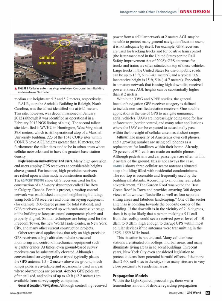
www.gpsworld.com January 2013 | GPS World 65
Integration with Other Technologies | GNSS deSiGN
median site heights are 5.7 and 5.2 meters, respectively.
RALR, atop the Archdale Building in Raleigh, North
Carolina, was the tallest identified site at 64.1 meters.
This site, however, was decommissioned in January
2012 (although it was identified as operational in a
February 2012 NGS listing of sites). The second tallest
site identified is WVHU in Huntington, West Virginia at
39.6 meters, which is still operational atop of a Marshall
University building. 223 of the 1543 CORS sites within
CONUS have AGL heights greater than 10 meters, and
furthermore the taller sites tend to be in urban areas where
cellular networks tend to have the greatest base-station
density.
High Precision and Networks: End Users. Many high-precision
end users employ GPS receivers at considerable heights
above ground. For instance, high-precision receivers
are relied upon within modern construction methods.
The adjacENt PHotos show GPS receivers used for the
construction of a 58-story skyscraper called The Bow
in Calgary, Canada. For this project, a rooftop control
network was established on top of neighboring buildings
using both GPS receivers and other surveying equipment
(for example, 360-degree prisms for total stations), and
GPS receivers were moved up with each successive stage
of the building to keep structural components plumb and
properly aligned. Similar techniques are being used for the
Freedom Tower, the new World Trade Center, in New York
City, and many other current construction projects.
Other terrestrial applications that rely on high-precision
GPS receivers at high altitudes include structural
monitoring and control of mechanical equipment such
as gantry cranes. At times, even ground-based survey
receivers can be substantially elevated. Although a
conventional surveying pole or tripod typically places
the GPS antenna 1.5 – 2 meters above the ground, much
longer poles are available and occasionally used in areas
where obstructions are present. 4-meter GPS poles are
often utilized, and poles of up to 40 ft (12.2 meters) are
available from survey supply companies.
General Location/Navigation. Although controlling received
power from a cellular network at 2 meters AGL may be
suitable to protect many general navigation/location users,
it is not adequate by itself. For example, GPS receivers
are used for tracking trucks and for positive train control
(the latter mandated in the United States per the Rail
Safety Improvement Act of 2008). GPS antennas for
trucks and trains are often situated on top of these vehicles.
Large trucks in the United States for use on public roads
can be up to 13 ft, 6 in (~4.1 meters), and a typical U.S.
locomotive height is 15 ft, 5 in (~4.7 meters). Especially
in a mature network that is using high downtilts, received
power at these AGL heights can be substantially higher
than at 2 meters.
Within the TWG and NPEF studies, the general
location/navigation GPS receiver category is defined
to include non-certified aviation receivers. One notable
application is the use of GPS to navigate unmanned
aerial vehicles. UAVs are increasingly being used for law
enforcement, border control, and many other applications
where the UAV can be expected to occasionally pass
within the boresight of cellular antennas at short ranges.
cellular. The majority of Americans own cell phones,
and a growing number are using cell phones as a
replacement for landlines within their home. Already,
70 percent of 911 calls are made on mobile phones.
Although pedestrians and car passengers are often within
2 meters of the ground, this is not always the case.
FiGUrE 9 shows three cellular sector antennas situated
atop a building ¿lled with residential condominiums.
The rooftop is accessible and frequently used by the
building inhabitants. According to an online real estate
advertisement, “The Garden Roof was voted the Best
Green Roof in Town and provides amazing 360 degree
views of downtown Nashville as well as four separate
sitting areas and fabulous landscaping.” One of the sector
antennas is pointing towards the opposite corner of the
building. If the downtilt is in the vicinity of 2–6 degrees,
then it is quite likely that a person making a 911 call
from the rooftop could see a received power level of –10
dBm to 0 dBm, high enough to disrupt GPS within most
cellular devices if the antennas were transmitting in the
1525–1559 MHz band.
This situation is not unusual. Many cellular base
stations are situated on rooftops in urban areas, and many
illuminate living areas in adjacent buildings. In recent
years, New York City even considered legislation to
protect citizens from potential harmful effects of the more
than 2,600 cell sites in the city, since many sites are in very
close proximity to residential areas.
Propagation ModelsWithin the LightSquared proceedings, there was a
tremendous amount of debate regarding propagation
▲ FiGUrE 9 Cellular antennas atop Westview Condominium Building in downtown Nashville.

GPS World | January 2013 www.gpsworld.com66
GNSS DESIGN | Integration with Other Technologies
models. Communication-system service providers
typically use propagation models that are conservative in
their estimates of received power levels in the sense that
they overestimate propagation losses. This conservatism
is necessary so that the service can be provided to end
users with high availability. From the standpoint of
potential victims of interference, however, it is seen as
far more desirable to underestimate propagation losses so
that interference can be kept below an acceptable level
a very high percentage of time. As shown in Figure 3,
some received power measurements from the Las Vegas
live-sky test indicate values even greater than would be
predicted using free-space propagation model. Statistical
models that allow for this possible were used in the FAA
Status Report. The general topic of propagation models
is worthy of future additional study if GPS interference
standards are to be developed.
Future ConsiderationsGPS is being modernized. Additionally, satellite
navigation users now enjoy the fact that the Russian
GLONASS system has recently returned to full strength
with the repopulation of its constellation. In the next
decade, satellite navigation users also eagerly anticipate
the completion of two other global GNSS constellations:
Europe’s Galileo and China’s Compass. Notably, between
the GPS modernization program and the deployment
of these other systems, satellite navigation users are
expected to soon be relying upon equipment that is multi-
frequency and that needs to process many more signals
with varied characteristics. New equipment offers an
opportunity to insert new technologies such as improved
¿ltering, but of course the need to process additional
signals and carrier frequencies may make GNSS
equipment more susceptible to interference as well.
Clearly, these developments will need to be carefully
assessed to support the establishment of GPS spectrum
interference standards.
SummaryThis article has identified a number of considerations for
the development of GPS interference standards, which
have been proposed by the PNT EXCOM. If the United
States proceeds with the development of such standards,
it is hoped that the information within this article will
prove useful to those involved.
Appendix: AGL Heights of CORS Network SitesThe National Geodetic Survey Continuously Operating
Reference Station (CORS) website provides lists of
CORS site locations in a number of different reference
frames. To determine the height above ground level (hagl
)
for each site within this study, two of these ¿les (igs08_
xyz_comp.txt and igs08_xyz_htdp.txt) were used. These
two ¿les provide the (x,y,z) coordinates of the antenna
reference point (ARP) for each site in the International
GNSS Service 2008 (IGS08) reference frame, which is
consistent with the International Terrestrial Reference
Frame (ITRF) of 2008. These coordinates are divided
into two ¿les by NGS, since the site listings also provide
site velocities and velocities are either computed (for
sites that have produced data for at least 2.5 years) or
estimated (for newer sites). The comp ¿le includes sites
with computed velocities and the htdp ¿le includes sites
with estimated velocities (using a NGS program known
as HTDP).
The data files can be used to readily produce height
above the ellipsoid, hellipsoid
, for each site. This height can be
found using well-known equations to convert from (x, y, z)
to (latitude, longitude, height). Obtaining estimates of hagl
requires information on the geoid height and terrain data,
per the relationship:
hagl
= hellipsoid – N - hterrain
(A-1)
For the results presented in this article, terrain data
was obtained from http://earthexplorer.usgs.gov in the Shuttle
Radar Topography Mission (SRTM) Digital Terrain
Elevation Data (DTED) Level 2 format. For this terrain
data, the horizontal datum is the World Geodetic
System (WGS 84). The vertical datum is Mean Sea
Level (MSL) as determined by the Earth Gravitational
Model (EGM) 1996. Each data file covers a 1º by 1º
degree cell in latitude/longitude, and individual points
are spaced 1 arcsec in both latitude and longitude. The
SRTM DTED Level 2 has a system design 16 meter
absolute vertical height accuracy, 10 meters relative
vertical height accuracy, and 20 meter absolute horizontal
circular accuracy. All accuracies are at the 90 percent
level. Considering the accuracies of the DTED data,
the differences between WGS-84 and IGS08 as well
as between the ARP and antenna phase center were
considered negligible. Geoid heights were interpolated
from 15-arcmin data available in the MATLAB Mapping
Toolbox using the egm96geoid function.
Lower AGL heights are preferred for CORS sites to
minimize motion between the antenna and the Earth’s
crust. However, many sites are at significant heights above
the ground by necessity, particularly in urban areas due to
the competing desire for good sky visibility.
Christopher J. hegarty is the director for communications, navigation, and surveillance engineering and spectrum with The MITRE Corporation. He received a D.Sc. degree in electrical engineering from George Washington University. He is currently the chair of the Program Management Committee of the RTCA, Inc., and co-chairs RTCA Special Committee 159 (GNSS). He is the co-editor/co-author of the textbook Understanding GPS: Principles and Applications, 2nd Edition.

www.gpsworld.com January 2013 | GPS World 67
Algorithms and Methods | innovAtion
This article deals with the problem
of position authentication. The
term “position authentication”
as discussed in this article is taken to
mean the process of checking whether
position reports made by a remote
user are truthful (Is the user where
they say they are?) and accurate (In
reality, how close is a remote user to the
position they are reporting?). Position
authentication will be indispensable to
many envisioned civilian applications.
For example, in the national airspace of
the future, some traf¿c control services
will be based on self-reported positions
broadcast via ADS-B by each aircraft.
Non-aviation applications where
authentication will be required include
tamper-free shipment tracking and
smart-border systems to enhance cargo
inspection procedures at commercial
ports of entry. The discussions that
follow are the outgrowth of an idea
¿rst presented by Sherman Lo and
colleagues at Stanford University (see
Further Reading).
For illustrative purposes, we will
focus on the terrestrial application of
cargo tracking. Most of the commercial
Àeet and asset tracking systems
available in the market today depend on
a GPS receiver installed on the cargo or
asset. The GPS receiver provides real-
time location (and, optionally, velocity)
information. The location and the time
when the asset was at a particular
location form the tracking message,
which is sent back to a monitoring
center to verify if the asset is traveling
in an expected manner. This method
of tracking is depicted graphically in
FIGURE 1.
The approach shown in Figure 1 has
at least two potential scenarios or fault
My UnIvERsIty, the University of New Brunswick, is one of the few institutes of higher learning still using Latin at its graduation exercises. The president and vice-chancellor of the university asks the members of the senate and board of governors present “Placetne vobis Senatores, placetne, Gubernatores, ut hi supplicatores admittantur?” (Is it your pleasure, Senators, is it your pleasure, Governors, that these supplicants be admitted?). In the Oxford tradition, a supplicant is a student who has qualified for their degree but who has not yet been admitted to it. Being a UNB senator, I was familiar with this usage of the word supplicant. But I was
a little surprised when I first read a draft of the article in this month’s Innovation column with its use of the word supplicant to describe the status of a GPS receiver.
If we look up the definition of supplicant in a dictionary, we find that it is “a person who makes a humble or earnest plea to another, especially to a person in power or authority.” Clearly, that describes our graduating students. But what has it got to do with a GPS receiver? Well, it seems that the word supplicant has been taken up by engineers developing protocols for computer communication networks and with a similar meaning. In this case, a supplicant (a computer or rather some part of its operating system) at one end of a secure local area network seeks authentication to join the
network by submitting credentials to the authenticator on the other end. If authentication is successful, the computer is allowed to join the network. The concept of supplicant and authenticator is used, for example, in the IEEE 802.1X standard for port-based network access control.
Which brings us to GPS. When a GPS receiver reports its position to a monitoring center using a radio signal of some kind, how do we know that the receiver or its associated communications unit is telling the truth? It’s not that difficult to generate false position reports and mislead the monitoring center into believing the receiver is located elsewhere — unless an authentication procedure is used. In this month’s column, we look at the development of a clever system that uses the concept of supplicant and authenticator to assess the truthfulness of position reports.
It’s not that difficult to generate false position reports.
InnovaTIon InSIGhTS with Richard Langley
Getting at the truthA Civilian GPS Position Authentication SystemZhefeng Li and Demoz Gebre-Egziabher
“Innovation” is a regular feature that discusses advances in GPS technology andits applications as well as the fundamentals of GPS positioning. The column is coordinated by Richard Langley of the Department of Geodesy and Geomatics Engineering, University of New Brunswick. He welcomes comments and topic ideas. To contact him, see the “Contributing Editors” section on page 6.

GPS World | January 2013 www.gpsworld.com68
innovation | algorithms and Methods
modes, which can lead to erroneous tracking of the asset. The
¿rst scenario occurs when an incorrect position solution is
calculated as a result of GPS RF signal abnormalities (such
as GPS signal spoo¿ng). The second scenario occurs when
the correct position solution is calculated but the tracking
message is tampered with during the transmission from the
asset being tracked to the monitoring center. The ¿rst scenario
is a falsi¿cation of the sensor and the second scenario is a
falsi¿cation of the transmitted position report.
The purpose of this article is to examine the problem of
detecting sensor or report falsi¿cation at the monitoring
center. We discuss an authentication system utilizing the
white-noise-like spreading codes of GPS to calculate an
authentic position based on a snapshot of raw IF signal from
the receiver.
Using White Noise as a WatermarkThe features for GPS position authentication should be very
hard to reproduce and unique to different locations and time.
In this case, the authentication process is reduced to detecting
these features and checking if these features satisfy some time
and space constraints. The features are similar to the well-
designed watermarks used to detect counterfeit currency.
A white-noise process that is superimposed on the GPS
signal would be a perfect watermark signal in the sense that it
is impossible reproduce and predict. FIGURE 2 is an abstraction
that shows how the above idea of a superimposed white-noise
process would work in the signal authentication problem. The
system has one transmitter, Tx , and two receivers, R
s and R
a.
Rs is the supplicant and R
a is the authenticator. The task of
the authenticator is to determine whether the supplicant is
using a signal from Tx or is being spoofed by a malicious
transmitter, Tm. R
a is the trusted source, which gets a copy
of the authentic signal, Vx(t) (that is, the signal transmitted
by Tx). The snapshot signal, V
s(t), received at R
s is sent to
the trusted agent to compare with the signal, Va(t), received
at Ra. Every time a veri¿cation is performed, the snapshot
signal from Rs is compared with a piece of the signal from
Ra. If these two pieces of signal match, we can say the
snapshot signal from Rs was truly transmitted from T
x. For
the white-noise signal, match detection is accomplished via a
cross-correlation operation (see Further Reading). The cross-
correlation between one white-noise signal and any other
signal is always zero. Only when the correlation is between
the signal and its copy will the correlation have a non-
zero value. So a non-zero correlation means a match. The
time when the correlation peak occurs provides additional
information about the distance between Ra and R
s.
Unfortunately, generation of a white-noise watermark
template based on a mathematical model is impossible. But,
as we will see, there is an easy-to-use alternative.
An Intrinsic GPS Watermark The RF carrier broadcast by each GPS satellite is modulated
by the coarse/acquisition (C/A) code, which is known and
which can be processed by all users, and the encrypted
P(Y) code, which can be decoded and used by Department
of Defense (DoD) authorized users only. Both civilians and
DoD-authorized users see the same signal. To commercial
GPS receivers, the P(Y) code appears as uncorrelated
noise. Thus, as discussed above, this noise can be used as a
watermark, which uniquely encodes locations and times. In a
typical civilian GPS receiver’s tracking loop, this watermark
signal can be found inside the tracking loop quadrature signal.
The position authentication approach discussed here
is based on using the P(Y) signal to determine whether a
user is utilizing an authentic GPS signal. This method uses
a segment of noisy P(Y) signal collected by a trusted user
(the authenticator) as a watermark template. Another user’s
(the supplicant’s) GPS signal can be compared with the
template signal to judge if the user’s position and time reports
are authentic. Correlating the supplicant’s signal with the
authenticator’s copy of the signal recorded yields a correlation
peak, which serves as a watermark. An absent correlation
peak means the GPS signal provided by the supplicant is
not genuine. A correlation peak that occurs earlier or later
than predicted (based on the supplicant’s reported position)
indicates a false position report.
System ArchitectureFIGURE 3 is a high-level architecture of our proposed position
authentication system. In practice, we need a short snapshot
of the raw GPS IF signal from the supplicant. This piece of
the signal is the digitalized, down-converted, IF signal before
the tracking loops of a generic GPS receiver. Another piece
of information needed from the supplicant is the position
solution and GPS Time calculated using only the C/A signal.
The raw IF signal and the position message are transmitted to
the authentication center by any data link (using a cell-phone
data network, Wi-Fi, or other means).
GPS satellite
Message packet
• Time stamp
• Location
User vehicle
(with GPS receiver)Monitoring center
GPS signal
Message channel
▲ FIGURE 1 A typical asset tracking system.

www.gpsworld.com January 2013 | GPS World 69
Algorithms and Methods | innovAtion
The authentication station keeps track of all the common
satellites seen by both the authenticator and the supplicant.
Every common satellite’s watermark signal is then obtained
from the authenticator’s tracking loop. These watermark
signals are stored in a signal database. Meanwhile, the
pseudorange between the authenticator and every satellite is
also calculated and is stored in the same database.
When the authentication station receives the data from the
supplicant, it converts the raw IF signal into the quadrature
(Q) channel signals. Then the supplicant’s Q channel signal
is used to perform the cross-correlation with the watermark
signal in the database. If the correlation peak is found at
the expected time, the supplicant’s signal passes the signal-
authentication test. By measuring the relative peak time of
every common satellite, a position can be computed. The
position authentication involves comparing the reported
position of the supplicant to this calculated position. If the
difference between two positions is within a pre-determined
range, the reported position passes the position authentication.
While in principle it is straightforward to do authentication
as described above, in practice there are some challenges
that need to be addressed. For example, when there is only
one common satellite, the only common signal in the Q
channel signals is this common satellite’s P(Y) signal. So the
cross-correlation only has one peak. If there are two or more
common satellites, the common signals in the Q channel
signals include not only the P(Y) signals but also C/A signals.
Then the cross-correlation result will have multiple peaks.
We call this problem the C/A leakage problem, which will be
addressed below.
C/A Residual FilterThe C/A signal energy in the GPS signal is about double the
P(Y) signal energy. So the C/A false peaks are higher than the
true peak. The C/A false peaks repeat every 1 millisecond. If
the C/A false peaks occur, they are greater than the true peak
in both number and strength. Because of background noise,
it is hard to identify the true peak from the correlation result
corrupted by the C/A residuals.
To deal with this problem, a high-pass ¿lter can be used.
Alternatively, because the C/A code is known, a match ¿lter
can be designed to ¿lter out any given GPS satellite’s C/A
signal from the Q channel signal used for detection. However,
this implies that one match ¿lter is needed for every common
satellite simultaneously in view of the authenticator and
supplicant. This can be cumbersome and, thus, the ¿ltering
approach is pursued here.
In the frequency domain, the energy of the base-band C/A
signal is mainly (56 percent) within a ±1.023 MHz band, while
the energy of the base-band P(Y) signal is spread over a wider
band of ±10.23 MHz. A high-pass ¿lter can be applied to Q
channel signals to ¿lter out the signal energy in the ±1.023
MHz band. In this way, all satellites’ C/A signal energy can
be attenuated by one ¿lter rather than using separate match
¿lters for different satellites.
FIGURE 4 is the frequency response of a high-pass ¿lter
designed to ¿lter out the C/A signal energy. The spectrum
of the C/A signal is also plotted in the ¿gure. The high-
pass ¿lter only removes the main lobe of the C/A signals.
Unfortunately, the high-pass ¿lter also attenuates part of the
▲ FIGURE 3 Architecture of position authentication system.
Vx(t)
Tx
Tm
Vm(t)
νs
νa
Va(t)
Ra
Rs
Vs(t)
GPS satellite
(at least four for
position authentication)
User vehicle
Cell-phone tower Authentication site
(law enforcement)
GPS signal
RF data uplink 0 1 2 3 4 5−80
−70
−60
−50
−40
−30
−20
−10
0
Frequency (MHz)
Gain (dB)
Filter frequency response
C/A signal spectrum
▲ FIGURE 2 Architecture to detect a snapshot of a white-noise signal.
▲ FIGURE 4 Frequency response of the notch filter.

GPS World | January 2013 www.gpsworld.com70
innovation | algorithms and Methods
P(Y) signal energy. This degrades the auto-correlation peak
of the P(Y) signal. Even though the gain of the high-pass
¿lter is the same for both the C/A and the P(Y) signals, this
effect on their auto-correlation is different. That is because
the percentage of the low-frequency energy of the C/A signal
is much higher than that of the P(Y) signal. This, however, is
not a signi¿cant drawback as it may appear initially. To see
why this is so, note that the objective of the high-pass ¿lter is
to obtain the greatest false-peak rejection ratio de¿ned to be
the ratio between the peak value of P(Y) auto-correlation and
that of the C/A auto-correlation. The false-peak rejection ratio
of the non-¿ltered signals is 0.5. Therefore, all one has to do is
adjust the cut-off frequency of the high-pass ¿lter to achieve a
desired false-peak rejection ratio.
The simulation results in FIGURE 5 show that one simple high-
pass ¿lter rather than multiple match ¿lters can be designed
to achieve an acceptable false-peak rejection ratio. The auto-
correlation peak value of the ¿ltered C/A signal and that of
the ¿ltered P(Y) signal is plotted in the ¿gure. While the
P(Y) signal is attenuated by about 25 percent, the C/A code
signal is attenuated by 91.5 percent (the non-¿ltered C/A auto-
correlation peak is 2). The false-peak rejection ratio is boosted
from 0.5 to 4.36 by using the appropriate high-pass ¿lter.
Position CalculationConsider the situation depicted in FIGURE 6 where the
authenticator and the supplicant have multiple common
satellites in view. In this case, not only can we perform
the signal authentication but also obtain an estimate of the
pseudorange information from the authentication. Thus, the
authenticated pseudorange information can be further used to
calculate the supplicant’s position if we have at least three
estimates of pseudoranges between the supplicant and GPS
satellites. Since this position solution of the supplicant
is based on the P(Y) watermark signal rather than the
supplicant’s C/A signal, it is an independent and authentic
solution of the supplicant’s position. By comparing this
authentic position with the reported position of the supplicant,
we can authenticate the veracity of the supplicant’s reported
GPS position.
The situation shown in Figure 6 is very similar to double-
difference differential GPS. The major difference between
what is shown in the ¿gure and the traditional double
difference is how the differential ranges are calculated.
Figure 6 shows how the range information can be obtained
during the signal authentication process. Let us assume that
the authenticator and the supplicant have four common GPS
satellites in view: SAT1, SAT2, SAT3, and SAT4. The signals
transmitted from the satellites at time t are S1(t), S
2(t), S
3(t),
and S4(t), respectively. Suppose a signal broadcast by SAT1 at
time t0 arrives at the supplicant at t
0 + ν
1
s where ν1
s is the travel
time of the signal. At the same time, signals from SAT2,
SAT3, and SAT4 are received by the supplicant. Let us denote
the travel time of these signals as ν2
s, ν3
s, and ν4
s, respectively.
These same signals will be also received at the authenticator.
We will denote the travel times for the signals from satellite
to authenticator as ν1
a, ν2
a, ν3
a, and ν4
a.
The signal at a receiver’s antenna is the superposition of the
signals from all the satellites. This is shown in FIGURE 7 where a
snapshot of the signal received at the supplicant’s antenna at
time t0 + ν
1
s includes GPS signals from SAT1, SAT2, SAT3,
and SAT4. Note that even though the arrival times of these
signals are the same, their transmit times (that is, the times
they were broadcast from the satellites) are different because
the ranges are different. The signals received at the supplicant
will be S1(t
0), S
2(t
0 + ν
1
s – ν2
s), S3(t
0 + ν
1
s – ν3
s), and S4(t
0 + ν
1
s –
ν4
s). This same snapshot of the signals at the supplicant is used
to detect the matched watermark signals from SAT1, SAT2,
SAT3, and SAT4 at the authenticator. Thus the correlation
peaks between the supplicant’s and the authenticator’s signal
should occur at t0 + ν
1
a, t0 + ν
1
s – ν2
s + ν2
a, t0 + ν
1
s – ν3
s + ν3
a,
and t0 + ν
1
s – ν4
s + ν4
a.
Referring to Figure 6 again, suppose the authenticator’s
−3 −2 −1 0 1 2 3−0.3
−0.1
0.1
0.3
0.5
0.7
0.9
← 0.7424
← 0.1701
Shift time (milliseconds)
Auto
−corr
ela
tion
Filtered P(Y) signal
Filtered C/A signal
SAT1
SAT2SAT3
SAT4
Authenticator
(xa, y
a, z
a)
Supplicant
(xs, y
s, z
s)
x
y
z
ECEF
1aS
2aS
3aS
4aS
2sS
3sS
4sS
1sS
▲ FIGURE 5 Auto-correlation of the filtered C/A and P(Y) signals.
▲ FIGURE 6 Positioning using a watermark signal.

www.gpsworld.com January 2013 | GPS World 71
Algorithms and Methods | innovAtion
position (xa, y
a, z
a) is known but the supplicant’s position
(xs, y
s, z
s) is unknown and needs to be determined. Because
the actual ith common satellite (xi, y
i, z
i) is also known to
the authenticator, each of the ρi
a, the pseudorange between
the ith satellite and the authenticator, is known. If ρi
s is the
pseudorange to the ith satellite measured at the supplicant, the
pseudoranges and the time difference satis¿es equation (1):
(1)
where χ21
is the differential range error primarily due to
tropospheric and ionospheric delays. In addition, c is the
speed of light, and t21
is the measured time difference as
shown in Figure 7. Finally, ρi
s for i = 1, 2, 3, 4 is given by:
(2)
If more than four common satellites are in view between the
supplicant and authenticator, equation (1) can be used to form
a system of equations in three unknowns. The unknowns are
the components of the supplicant’s position vector rs = [x
s,
ys, z
s]T. This equation can be linearized and then solved using
least-squares techniques. When linearized, the equations have
the following form:
(3)
where δrs = [δx
s, δy
s, δz
s]T, which is the estimation error of the
supplicant’s position. The matrix A is given by
where is the line of sight vector from the supplicant to the
ith satellite. Finally, the vector δm is given by:
(4)
where is the ith satellite’s position error, δρi
a is the
measurement error of pseudorange ρi
a or pseudorange noise.
In addition, δtij is the time difference error. Finally, δχ
ij is the
error of χij de¿ned earlier.
Equation (3) is in a standard form that can be solved by a
weighted least-squares method. The solution is
(5)
where R is the covariance matrix of the measurement error
vector δm. From equations (3) and (5), we can see that the
supplicant’s position accuracy depends on both the geometry
and the measurement errors.
Hardware and SoftwareIn what follows, we describe an authenticator which is
designed to capture the GPS raw signals and to test the
performance of the authentication method described above.
Since we are relying on the P(Y) signal for authentication,
the GPS receivers used must have an RF front end with at
least a 20-MHz bandwidth. Furthermore, they must be
coupled with a GPS antenna with a similar bandwidth. The
RF front end must also have low noise. This is because the
authentication method uses a noisy piece of the P(Y) signal
at the authenticator as a template to detect if that P(Y) piece
exists in the supplicant’s raw IF signal. Thus, the detection
is very sensitive to the noise in both the authenticator and
the supplicant signals. Finally, the sampling of the down-
converted and digitized RF signal must be done at a high rate
because the positioning accuracy depends on the accuracy
of the pseudorange reconstructed by the authenticator.
The pseudorange is calculated from the time-difference
measurement. The accuracy of this time difference depends
on the sampling frequency to digitize the IF signal. The high
sampling frequency means high data bandwidth after the
sampling.
The authenticator designed for this work and shown in
FIGURE 8 satis¿es the above requirements. A block diagram of
the authenticator is shown in Figure 8a and the constructed
unit in Figure 8b. The IF signal processing unit in the
authenticator is based on the USRP N210 software-de¿ned
radio. It offers the function of down converting, digitalization,
and data transmission. The ¿rmware and ¿eld-programmable-
gate-array con¿guration in the USRP N210 are modi¿ed to
integrate a software automatic gain control and to increase
the data transmission ef¿ciency. The sampling frequency is
100 MHz and the effective resolution of the analog-to-digital
conversion is 6 bits. The authenticator is battery powered and
can operate for up to four hours at full load.
Performance ValidationNext, we present results demonstrating the performance of the
Supplicant Authenticator
▲ FIGURE 7 Relative time delays constrained by positions.

GPS World | January 2013 www.gpsworld.com72
innovation | algorithms and Methods
authenticator described above. First, we present results that
show we can successfully deal with the C/A leakage problem
using the simple high-pass ¿lter. We do this by performing
a correlation between snapshots of signal collected from the
authenticator and a second USRP N210 software-de¿ned
radio. FIGURE 9a is the correlation result without the high-
pass ¿lter. The periodic peaks in the result have a period of
1 millisecond and are a graphic representation of the C/A
leakage problem. Because of noise, these peaks do not have
the same amplitude. FIGURE 9b shows the correlation result
using the same data snapshot as in Figure 9a. The difference
is that Figure 9b uses the high-pass ¿lter to attenuate the
false peaks caused by the C/A signal residual. Only one peak
appears in this result as expected and, thus, con¿rms the
analysis given earlier.
We performed an experiment to validate the authentication
performance. In this experiment, the authenticator and
the supplicant were separated by about 1 mile (about 1.6
kilometers). The location of the authenticator was ¿xed.
The supplicant was then sequentially placed at ¿ve points
along a straight line. The distance between two adjacent
points is about 15 meters. The supplicant was in an open
area with no tall buildings or structures. Therefore, a
suf¿cient number of satellites were in view and multipath,
if any, was minimal. The locations of the ¿ve test points are
shown in FIGURE 10.
The ¿rst step of this test was to place the supplicant at point
A and collect a 40-millisecond snippet of data. This data was
then processed by the authenticator to determine if:
◾ The signal contained the watermark. We call this the
“signal authentication test.” It determines whether a
genuine GPS signal is being used to form the supplicant’s
position report.
◾ The supplicant is actually at the position coordinates that
they say they are. We call this the “position authentication
test.” It determines whether or not falsi¿cation of the
position report is being attempted.
Next, the supplicant was moved to point B. However,
in this instance, the supplicant reports that it is still located
at point A. That is, it makes a false position report. This is
repeated for the remaining positions (C through E) where
at each point the supplicant reports that it is located at point
A. That is, the supplicant continues to make false position
reports.
In this experiment, we have ¿ve common satellites
between the supplicant (at all of the test points A to E) and
▲ FIGURE 8 a) Block diagram of GPS position authenticator; (b) photo of constructed unit.
GPS antenna
LNA
Battery
Down-converter(DBSRX2)
A/D converter(USRP N210)
OCXO
Portable authenticator
Gigabit Ethernet Laptop(with SSD)
Channel 1 PRN: 7 Correlation Result (window: 40 milliseconds)
1.0
0.5
0
–0.5
–1.0
0 1000 2000 3000 4000 5000 6000 7000 8000 9000
Offset time (microseconds)
10000
Time = 5117.280 microseconds
Channel 1 PRN: 7 Correlation Result (window: 40 milliseconds)
1.0
0.5
0
–0.5
–1.0
0 1000 2000 3000 4000 5000 6000 7000 8000 9000
Offset time (microseconds)
10000
Time = 1126.110 microseconds
b)
b)
a)
a)
▲ FIGURE 9 Example of cross-correlation detection results: (a) without high-pass filter and (b) with high-pass filter.

www.gpsworld.com January 2013 | GPS World 73
Algorithms and Methods | innovAtion
the authenticator. The results of the
experiment are summarized in TABLE 1.
If we can detect a strong peak for every
common satellite, we say this point
passes the signal authentication test
(and note “Yes” in second column of
Table 1). That means the supplicant’s
raw IF signal has the watermark signal
from every common satellite. Next, we
perform the position authentication test.
This test tries to determine whether the
supplicant is at the position it claims to
be. If we determine that the position
of the supplicant is inconsistent with
its reported position, we say that the
supplicant has failed the position
authentication test. In this case we put a
“No” in the third column of Table 1. As
we can see from Table 1, the performance
of the authenticator is consistent with
the test setup. That is, even though the
wrong positions of points (B, C, D,
E) are reported, the authenticator can
detect the inconsistency between the
reported position and the raw IF data.
Furthermore, since the distance between
two adjacent points is 15 meters, this
implies that resolution of the position
authentication is at or better than 15
meters. While we have not tested it,
based on the timing resolution used
in the system, we believe resolutions
better than 12 meters are achievable.
ConclusionIn this article, we have described a GPS
position authentication system. The
authentication system has many potential
applications where high credibility of
a position report is required, such as
cargo and asset tracking. The system
detects a speci¿c watermark signal in
the broadcast GPS signal to judge if a
receiver is using the authentic GPS signal.
The differences between the watermark
signal travel times are constrained by
the positions of the GPS satellites and
the receiver. A method to calculate an
authentic position using this constraint is
discussed and is the basis for the position
authentication function of the system. A
hardware platform that accomplishes this
was developed using a software-de¿ned
radio. Experimental results demonstrate
that this authentication methodology
is sound and has a resolution of better
than 15 meters. This method can also be
used with other GNSS systems provided
that watermark signals can be found.
For example, in the Galileo system, the
encrypted Public Regulated Service
signal is a candidate for a watermark
signal.
In closing, we note that before
any system such as ours is ¿elded, its
performance with respect to metrics
such as false alarm rates (How often
do we Àag an authentic position
report as false?) and missed detection
probabilities (How often do we fail to
detect false position reports?) must be
quanti¿ed. Thus, more analysis and
experimental validation is required.
AcknowledgmentsThe authors acknowledge the United
States Department of Homeland Se-
curity (DHS) for supporting the work
reported in this article through the
National Center for Border Security
and Immigration under grant number
2008-ST-061-BS0002. However, any
opinions, ¿ndings, conclusions or rec-
ommendations in this article are those
of the authors and do not necessarily
reÀect views of the DHS. This article
is based on the paper “Performance
Analysis of a Civilian GPS Position
Authentication System” presented at
PLANS 2012, the Institute of Electri-
cal and Electronics Engineers / Insti-
tute of Navigation Position, Location
and Navigation Symposium held in
Myrtle Beach, South Carolina, April
23–26, 2012.
ManufacturersThe GPS position authenticator uses
an Ettus Research LLC (www.ettus.
com) model USRP N210 software-
de¿ned radio with a DBSRX2 RF
daughterboard.
ZhEfEng Li is a Ph.D. candidate in the Department of Aerospace Engineering and Mechanics at the University of Minnesota, Twin Cities. His research interests include GPS signal processing, real-time implementation of signal processing algorithms, and the authentication methods for civilian GNSS systems.
DEmoZ gEBrE-EgZiABhEr is an associate professor in the Department of Aerospace Engineering and Mechanics at the University of Minnesota, Twin Cities. His research deals with the design of multi-sensor navigation and attitude determination systems for aerospace vehicles ranging from small unmanned aerial vehicles to Earth-orbiting satellites.
Further Readingfor references related to this article, go to gpsworld.com and click on Innovation in the navigation bar.
MORE ONLINE
Location Pass Signal Authentication?
Pass Position Authentication?
A Yes Yes
B Yes No
C Yes No
D Yes No
E Yes No
▲ TABLE 1 Five-point position authentication results.
▲ figUrE 10 Five-point field test. Image courtesy of Google.

GPS World | January 2013 www.gpsworld.com74
ProfeSSional oem e-neWSletter
Whatever happed to Allen Osborne
Associates (AOA)? As a 1994
report (seeking a receiver for a “GPS
Sounder” task) stated, “Signal-to-noise
ratio tests of three high-performance
GPS receivers in severe multipath
conditions clearly show the Alllen
Osborne Associates TurboRogue SNR-
8000 is superior in locking and tracking
C/A, P1 and P2 codes at very low
receiver-to-satellite elevation angles.”
The advanced features of the
TurboRogue may well have been
key in AOA receivers being used for
a large number of ground reference
applications, including Monitor Station
Receivers for the U.S. Air Force GPS
Operational Control Segment (OCS).
AOA was acquired in 2004, and the
GPS group now resides and thrives
within the Communication Systems
Division of ITT Exelis Corporation
(ITT). Those AOA products and
technology have contributed to the ITT
military GPS receiver group becoming a
leading SAASM receiver supplier.
Exelis also has a Geospatial Systems
group, home to the GPS Payload,
Receiver and Control Systems group,
currently developing the ground
reference receiver as part of Raytheon’s
team for the next-generation GPS
Operational Control Segment (OCX).
Geospatial Systems has also been
continuously involved in the supply of
GPS payloads on every GPS satellite
launched and has accumulated more
than 500 years of on-orbit payload
life. Geospatial Systems is also part
of the Lockheed Martin team that is
developing and building the satellite
payloads for tomorrow’s GPS III
space segment. ITT is developing and
integrating the navigation payloads for
eight GPS IIIA satellites.
Today ITT boasts that it is the only
GPS systems developer to have been
a key contributor to all three GPS
program segments (space, OCS, and
user) with both legacy and modernized
equipment.
The receiver guys in Van Nuys have
fielded a series of SAASM-based
receivers over the years, beginning
with the EGR-1020, which has gone
into a large number of Single Channel
Ground and Airborne Radio Systems.
SINCGARS is a combat net radio
currently used by U.S. and allied
military forces, adding position and
GPS time-sync to each radio terminal.
The handheld control display allows
each radio operator to see the location in
real-time of all SINCGARS-equipped
friendly-force groups, providing active
situational awareness on the battlefield.
The next generation EGR-2000
Small Serial Interface (SSI) SAASM
receiver has been integrated into
“an in-country GPS designed and
manufactured system of a U.S.
International Ally,” and can be found in
terminals, radios, and handhelds.
This brings us to the current ITT
receiver product, known as the EGR-
2500. Integration and miniaturization
have reduced the EGR-2500 to half the
size of the SSI receiver. With the same
capability to track through reduced
signal levels and producing high-
precision carrier phase and pseudorange,
its not surprising that the EGR-2500 has
found new OEM applications.
Both Geodetics and Technology
Advancement Group (TAG) have
worked with ITT to integrate the EGR-
2500 into their products to achieve
centimeter-level RTK positioning. The
EGR provides high-quality, variable
rate observations at up to 10 Hz for up
to 24 different satellite signals, enabling
Geodetics and TAG to offer anti-
spoofing RTK performance. With the
addition of external inertial aiding, the
EGR can also maintain a high-quality
RTK solution under high dynamics.
But the SAASM receiver world is
becoming even more competitive, and
ITT is developing yet another generation
of receiver, further improving power
consumption and performance. A pair
of ARM 9 processors has been added,
along with circuitry that is software-
controlled to reduce power to blocks
not being used, so the next EGR will
have reduced size, weight, and cost and
is targeted to consume 500 milliwatts
in low-power mode. The enhanced
correlator array design will dramatically
reduce time-to-first fix, and with today’s
operational environment in mind, an
added front-end filter reduces the effects
of interference and jamming.
Excerpted. Read more at
gpsworld.com/category/opinions.
An Evolving SAASM Receiver StoryTony Murfin
CoPyriGht 2013 north CoaSt media, llC. All rights reserved. No part of this publication may be reproduced or transmitted in any form by any means, electronic or mechanical including by photocopy, recording, or information storage and retrieval without permission in writing from the publisher. Authorization to photocopy items for internal or personal use, or the internal or personal use of specific clients is granted by North Coast Media, LLC for libraries and other users registered with the Copyright Clearance Center, 222 Rosewood Dr, Danvers, MA 01923, phone 978-750-8400, fax 978-750-4470. Call for copying beyond that permitted by Sections 107 or 108 of the U.S. Copyright Law.
PrivaCy notiCe: North Coast Media LLC provides certain customer contact data (such as customers’ names, addresses, phone numbers and email addresses) to third parties who wish to promote relevant products, services and other opportunities which may be of interest to you. If you do not want North Coast Media LLC to make your contact information available to third parties for marketing purposes, simply call 847-763-4942 between the hours of 8:30 am and 5 pm (CT) and a customer service representative will assist you in removing your name from North Coast Media LLC’s lists.
GPS WORLD (ISSN 1048-5104) is published monthly by North Coast Media LLC, IMG Center, 1360 East 9th Street, Suite 1070, Cleveland, OH 44114. SUBSCriPtion rateS: One year $80, two years $129 (U.S. and possessions), one year $96, two years $151 (Canada and Mexico) and one year $155, two years $255 (all other countries). International pricing includes air-expedited service. Single copies (prepaid only) $7 in the United States $9 all other countries. Back issues, if available, are $19 in the U.S. and possessions, $23 all other countries. Include $6.50 per order plus $2 per additional copy for U.S. postage and handling. Periodicals postage paid at Cleveland OH 44101-9603 and additional mailing offices. PoStmaSter: Please send address change to GPS World, Po Box 2090, Skokie, il 60076. Printed in the U.S.A.
▲ ARMy SINCGARS has Exelis EGR-1020 inside.
Tony Murfin’s monthly Professional OEM
newsletter is sponsored by:Subscribe free at www.gpsworld.com/subscribe

www.navcomtech.com
Ultra RTK & RTK Extend™
StarFire™ GNSS License Included
LAND-PAKStarFire + RTK Survey System
Now Offering NavCom FieldGenius & SurvCE Software Choices
Now With More Options
We understand that to do the job right, you need all the right tools. No matter your software choice, NavCom’s FieldGenius & SurveyCAD
bundle or NavCom’s SurvCE & Survey software bundle, you’ll still have a complete land survey system that also includes full GNSS sup-
port, an online video training library, GNSS post processing software, all hardware & accessories, a three year warranty, and our 5cm global
accuracy StarFire™ Network Included.
With StarFire Over IP ReliabilityOur LAND-PAK complete survey system offers the power of RTK level accuracy with the added benefi t of 5cm StarFire global accuracy
when RTK corrections are not available. With StarFire Over IP delivery, LAND-PAK users can now have reliable, continued service even
when the receiver loses communication with the StarFire satellite. StarFire Over IP delivery allows users to ride through comunication out-
ages over extended periods, whether you’re working in an urban canyon or high latitude conditions.