GPS-Squitter Automatic Dependent Surveillance Broadcast ... · GPS-Squitter Automatic Dependent...
73
Project Report ATC-235 GPS-Squitter Automatic Dependent Surveillance Broadcast: Flight Testing in the Gulf of Mexico R. E. Boisvert M. L. Burrows S. R. Bussolari G. H. Knittel M. R. Owen K. W. Saunders 13 October 1995 Lincoln Laboratory MASSACHUSETTS INSTITUTE OF TECHNOLOGY LEXINGTON, MASSACHUSETTS Prepared for the Federal Aviation Administration, Washington, D.C. 20591 This document is available to the public through the National Technical Information Service, Springfield, VA 22161
Transcript of GPS-Squitter Automatic Dependent Surveillance Broadcast ... · GPS-Squitter Automatic Dependent...

Project ReportATC-235
GPS-Squitter Automatic Dependent Surveillance Broadcast: Flight Testing
in the Gulf of Mexico
R. E. BoisvertM. L. BurrowsS. R. Bussolari
G. H. KnittelM. R. Owen
K. W. Saunders
13 October 1995
Lincoln Laboratory MASSACHUSETTS INSTITUTE OF TECHNOLOGY
LEXINGTON, MASSACHUSETTS
Prepared for the Federal Aviation Administration, Washington, D.C. 20591
This document is available to the public through
the National Technical Information Service, Springfield, VA 22161

This document is disseminated under the sponsorship of the Department of Transportation in the interest of information exchange. The United States Government assumes no liability for its contents or use thereof.

1. Report No.
ATC-235
2. Government Accession No.
TECHNICAL REPORT STANDARD TITLE PAGE
3. Recipient's Catalog No.
4. Title and Subtitle
GPS-Squitter Automatic Dependent Surveillance Broadcast:Flight Testing in the Gulf of Mexico
7. Author(s)R.E. Boisvert, M.L. Burrows, S.R. Bussolari, G.H. Knittel, M.R. Owen, andK.W. Saunders
9. Performing Organization Name and Address
Lincoln Laboratory, MIT244 Wood StreetLexington, MA 02173-9108
12. Sponsoring Agency Name and AddressDepartment of TransportationFederal Aviation AdministrationSystems Research and Development ServiceWashington, DC 20591
15. Supplementary Notes
5. Report Date13 October 1995
6. Performing Organization Code
8. Performing Organization Report No.
ATC-235
10. Work Unit No. (TRAIS)
11. Contract or Grant No.
DTFAO1-93-Z-02012
13. Type of Report and Period Covered
14. Sponsoring Agency Code
This report is based on studies performed at Lincoln Laboratory, a center for research operated by Massachusetts Institute ofTechnology under Air Force Contract Fl9628-95-C-0002.
16. Abstract
During November - December 1994, MIT Lincoln Laboratory conducted a field evaluation ofthe air surveillance capabilities of GPS-Squitter in the Gulf of Mexico. Three squitter groundstations were located in the vicinity of Morgan City, Louisiana, for this evaluation: two were locatedon offshore oil platforms, and the third was located at an onshore heliport. Surveillance coveragetests were flown over the Gulf with three test aircraft-two helicopters and one Cessna 421 fixedwing aircraft. The helicopters flew at altitudes ranging from 100 to 2000 feet above sea level and theCessna flew at 7500 and 20,000 feet. Extended squitter messages broadcast by each of the testaircraft provided aircraft position and identification.
This report documents results of these tests and compares measured coverage to predictedcoverage from the ground stations. Based on the good agreement between predicted and measuredperformance, a description of a possible operational system is included that would provide surveillanceof the entire Gulf region serviced by oil platform helicopters. The report concludes that GPSSquitter is a near-term option for providing accurate, real-time surveillance of aircraft operating inthe offshore airspace in the Gulf of Mexico.
17. Key Words
Automatic Dependent SurveillanceModeSGulf of MexicoGPS
GPS-Squitteraircraft surveillancehelicopterMode S transponder
18. Distribution Statement
This document is available to the public through theNational Technical Information Se~vice,
Springfield, VA 22161.
19. Security Classif. (of this report)
Unclassified
FORM DOT F 1700.7 (8-72)
20. Security Classif. (of this page)
Unclassified
Reproduction of completed page authorized
21. No. of Pages
92
22. Price

EXECUTIVE SUMMARY
GPS-Squitter is a technology for aircraft surveillance in which aircraft broadcast their GPSdetermined positions to all listeners via the Mode S data link. It can be used to provide aircrafttraffic displays, on the ground for controllers and in the cockpit for pilots. It is compatible withexisting ground-based beacon interrogator radars and is an evolutionary way to move fromground-radar surveillance to Automatic Dependent Surveillance.
During a July 1994 meeting, the FAA requested that MIT Lincoln Laboratory conduct ademonstration of GPS-Squitter in the Gulf of Mexico. Shortly thereafter, in November-December1994, a field evaluation of GPS-Squitter for air surveillance was held in the Gulf. Objectives ofthis evaluation were to determine the suitability of GPS-Squitter for air surveillance in general, andmore specifically for air surveillance of helicopters servicing oil platforms in the Gulf of Mexico.
The offshore region of the Gulf of Mexico, encompassing approximately 1800 oilplatforms with helipads, is a busy flight zone with 600 helicopters conducting an average of 5000flights per day. At present, there is no radar coverage for these flights because they are too low tobe covered by shore radar. There is a need for accurate real-time surveillance of the aircraft forboth increased safety and efficiency reasons.
For the evaluation, three squitter ground stations were located in the vicinity of MorganCity, Louisiana; one at an onshore Petroleum Helicopters Inc. (PHI) heliport and two on offshoreoil platforms. Three aircraft were equipped with avionics to squitter, or radiate semi-regularly intime, their GPS positions and other key flight data; two of these were helic~pters and one was aCessna 421 fixed-wing aircraft. Squitter data received by the ground stations were sent to a centralcontrol computer via a satcom link, a microwave link, and a direct wire link. The computercorrelated the data and transmitted it to a local display at the PHI heliport and to remote displays inthe Houston ARTCC and the New Orleans TRACON.
Many tests of coverage were flown, for altitudes varying from 100 feet above sea level to20,000 feet. Predictions of coverage from each ground station were prepared in advance and usedto evaluate measurements. Coverage was generally excellent within ground station line of sightand was consistent with predicted performance. The two ground stations on the oil platforms,which used commercial DME antennas at heights of 160 feet, had signal-to-noise-limited rangesof 100 nmi.
Several tests were run to determine the effect of anomalous propagation on GPS-Squitterperformance. No measurable effects were found during the observation period. Other studies anddata suggest that anomalous propagation should have little or no effect on GPS-Squitterperformance.
Several demonstrations of system performance were held during December 1994 forvisitors from the FAA, oil companies, helicopter and communications companies, and from GreatBritain. The system performed well with only rare down time for communications link problems.It was concluded that GPS-Squitter technology is viable for air surveillance and is well suited forhelicopter surveillance in the Gulf of Mexico.
ill

ACKNOWLEDGMENTS
The authors wish to express appreciation to the Federal Aviation Administration sponsorsand program managers for supporting the Gulf of Mexico field evaluation of GPS-Squittertechnology.
Ron Jones, AND-310
Carmine Primeggia, ASD-IIO
Karen Burcham, AND-310
Also, the authors would like to thank the following organizations for their support, whichsignificantly contributed to a successful evaluation.
FAA Southwest Region (ASW-200, ASW-400, ASW-500)
FAA Vertical Flight/GA Program Office AND-610
FAA Air Traffic Procedures/GPS Office ATP-20
FAA Houston ARTCC
FAA New Orleans TRACON
Helicopter Safety Advisory Conference
Petroleum Helicopters, Inc.
PetroCom
Shell Oil Company
Noreen Explorer
Daley Tower Service
NORAD
In addition, we are indebted to our colleagues: Jonathan Bernays, who supervised theavionics equipment and its operation; Bill Harman, who estimated coverage of an operationalsystem; and Walter Brown, who was the Lincoln Laboratory interface with many of the FAAgroups listed above. We are also grateful to the many members of the MIT Lincoln LaboratoryFlight Facility, Group 42, and Group 41 who worked on all aspects of this endeavor.
v

TABLE OF CONTENTS
Executive Summary ill
Acknowledgments vList of Illustrations IX
List of Tables Xill
1. INTRODUCTION
1.1 Background 11.2 GPS-Squitter 21.3 Report Overview 3
2. TEST OBJECTIVES 5
3. TEST CONFIGURATION 7
3.1 Test Aircraft 73.2 Ground Equipment 83.3 Communications Performance Issues 22
4. PREDICTED COVERAGE 27
5. FLIGHT TEST RESULTS 33
5.1 Wiggins Bell 206 Helcopter 335.2 PHI Bell 206 Helicopter 485.3 Cessna 421 Fixed-Wing Airplane 485.4 Comparison of Predicted and Measured Performance 59
6. POSSIBLE OPERATIONAL SYSTEM 63
7. SUMMARY 67
APPENDIX A. PROPAGATION TESTING 69
REFERENCES 77
vii

FigureNo.
LIST OF ILLUSTRATIONS
Page
1-1 Infonnation contained within the three types of extended squitter messages. 2
1-2 Surveillance applications of GPS-Squitter include: air-ground surveillance,TCAS (Traffic Alert and Collision Avoidance System), CDTI (CockpitDisplay of Traffic Infonnation), and surface surveillance. 3
3-1 Overview of avionics and ground equipment used in the Gulf of Mexico. 7
3-2 Aircraft used in the Gulf of Mexico testing (a) Wiggins Bell 206 helicopter,(b) PHI Bell 206 helicopter, and (c) Cessna 421 aircraft. 9
3-3 Configuration of the test aircraft avionics. 11
3-4 Ground Interrogator/Receiver Units (GIRUs) with antenna configurationsused in the Gulf of Mexico: (a) directional antenna used at the PHI heliport,and (b) omnidirectional-in-azimuth antenna used on the oil platfonns. 13
3-5 Ground station block diagram. 15
3-6 Ground station equipment rack including GIRU processor and Sunworkstation. 17
3-7 Communication link from the PHI ground station to the Central ControlComputer. 19
3-8 Communication link from the EI 100 ground station to the Central ControlComputer. 19
3-9 Communication link from the SMI 268 ground station to the Central ControlComputer. 21
3-10 Communications from the Central Control Computer to the traffic displays. 21
3-11 Traffic display example showing test targets, VOR radials, ground stationlocations, Gulf coastline, and major roads. 23
4-1 Ground station link margin for an aircraft at 2000-ft altitude. 29
4-2 Ground station link margin for an aircraft at 300-ft altitude. 30
4-3 Ground station link margin for an aircraft at 20,OOO-ft altitude. 30
5-1 Transponder antenna mounted on the underside of the Wiggins Bell 206helicopter. 35
5-2 Antenna pattern for the Wiggins Bell 206 transponder antenna. 37
5-3a-b GPS-Squitter surveillance of the Wiggins Bell 206, during a flight to SMI268 at l00-ft altitude, from the ground station at (a) PHI and (b) SMI 268. 38
5-3c GPS-Squitter surveillance of the Wiggins Bell 206, during a flight to SMI268 at lOO-ft altitude, from the ground station at EI 100. 39
IX

FigureNo. Page
5-3d GPS-Squitter surveillance of the Wiggins Bell 206, during a flight to SMI268 at 100-ft altitude, from the three ground stations combined. 40
5-4a-b GPS-Squitter surveillance of the Wiggins Bell 206, during a flight to EI 100at 100-ft altitude, from the ground station at (a) PHI and (b) SMI 268. 43
5-4c GPS-Squitter surveillance of the Wiggins Bell 206, during a flight to EI 100at lOO-ft altitude, from the ground station at EI 100. 44
5-4d GPS-Squitter surveillance of the Wiggins Bell 206, during a flight to EI 100at 100-ft altitude, from the three ground stations combined. 45
5-5 Combined GPS-Squitter surveillance of the Wiggins Bell 206 during flightsto SMI 268 and EI 100 at 300-ft altitude. 46
5-6 Combined GPS-Squitter surveillance of the Wiggins Bell 206 during a flightto EI 100 at 2000-ft altitude. 47
5-7 Combined GPS-Squitter surveillance of the PHI Bell 206. 49
5-8a GPS-Squitter surveillance of the Cessna 421, during a long range flight at20,000-ft altitude, from the ground station at PHI. 50
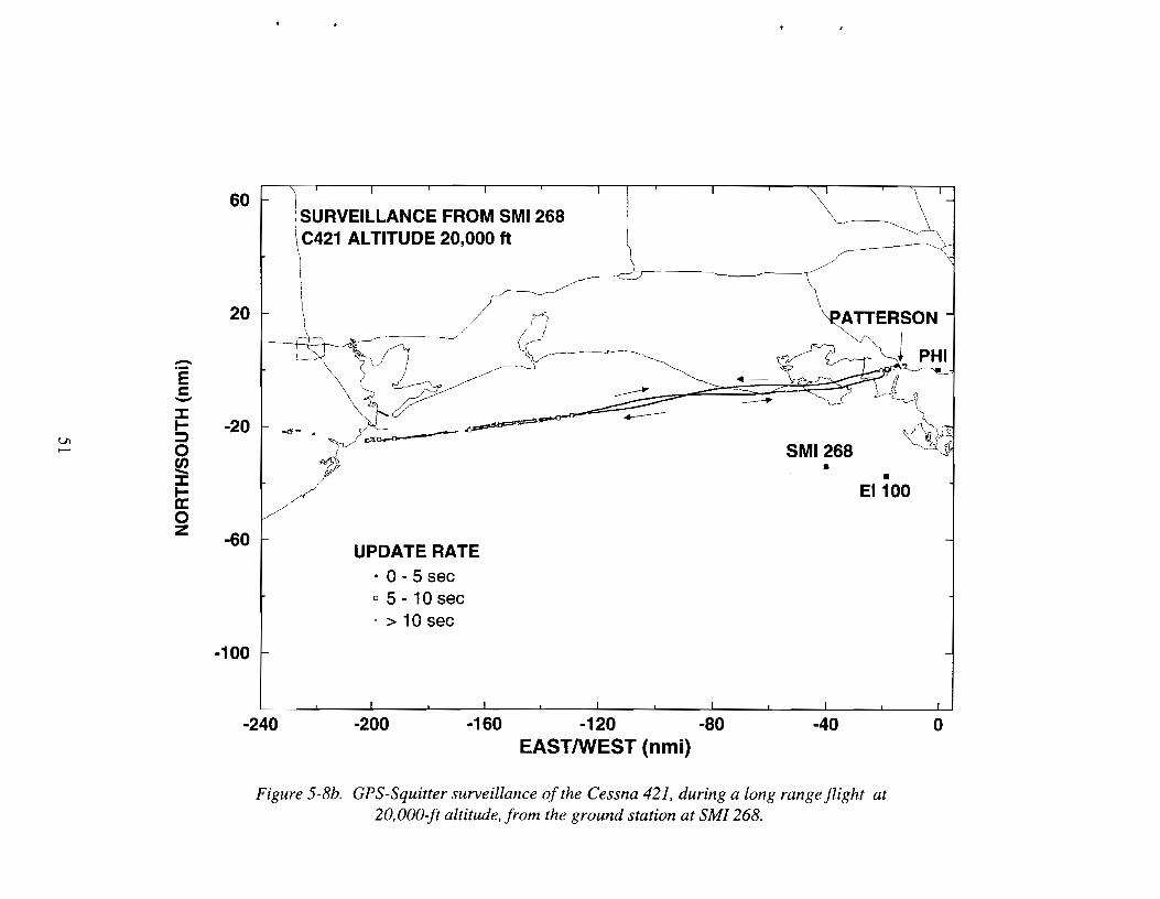
5-8b GPS-Squitter surveillance of the Cessna 421, during a long range flight at20,000-ft altitude, from the ground station at SMI 268. 51
5-8c GPS-Squitter surveillance of the Cessna 421, during a long range flight at20,000-ft altitude, from the ground station at EI 100. 52
5-8d GPS-Squitter surveillance of the Cessna 421, during a long range flight at20,000-ft altitude, from the three ground stations combined. 53
5-9a GPS-Squitter surveillance of the Cessna 421, during a long range flight at7500-ft altitude, from the ground station at PHI. 55
5-9b GPS-Squitter surveillance of the Cessna 421, during a long range flight at7500-ft altitude, from the ground station at SMI 268. 56
5-9c GPS-Squitter surveillance of the Cessna 421, during a long range flight at7500-ft altitude, from the ground station at EI 100. 57
5-9d GPS-Squitter surveillance of the Cessna 421, during a long range flight at7500-ft altitude, from the three ground stations combined. 58
5-10 Combined GPS-Squitter surveillance of the Cessna 421 during flights alongIFR routes at 7500-ft altitude. 60
6-1 Predicted coverage of an offshore region operational system having 10ground stations on shore towers and 13 ground stations on oil platforms, foraircraft at 300-ft altitude. 64
6-2 Equipment for an offshore region operational system providing both ADS-Bsurveillance and two-way data link. 65
x

FigureNo. Page
A-I Flight path taken by Wiggins Bell 206 helicopter during propagation testing. 70
A-2 The cumulative missed squitter count for the ground station at SMI 268during the return leg of the daytime flight that used normal systemsensitivity. 71
A-3 The cumulative missed squitter count for the PHI ground station during thesame return flight leg as Figure A-2. 72
A-4 The cumulative missed squitter count for the SMI 268 ground station duringthe return flight leg of the daytime flight in which the system sensitivity wasreduced by 6 dB. 72
A-5 The cumulative missed squitter count for the PHI ground station during thesame return flight leg as Figure A-4. 73
Xl

TableNo.
4-1
4-2
5-1
5-2
5-3
5-4
LIST OF TABLES
Link Budget Items
Predicted Ground Station Surveillance Range with a 4 dB Link Margin
Surveillance During Cessna 421 Flight at 20,OOO-ft Altitude
Surveillance During Cessna 421 Flight at 7500-ft Altitude
Estimated and Measured Maximum Range from PHI Ground Station
Estimated and Measured Maximum Range from Platform Ground Stations
X11l
Page
28
31
54
59
61
61

1. INTRODUCTION
1.1 BACKGROUND
The offshore region of the Gulf of Mexico from Texas to the Florida panhandle has beenthe focus of intense petroleum exploration and production activity. Approximately 1800 oilplatforms with helipads are located in these waters. At any given time, up to 10,000 men andwomen are located on the platforms. The safe and efficient transport of workers and materiel toand from the oil platforms is essential to the commercial viability of the Gulf petroleum industry.Much of this transportation is provided by the 600 helicopters that operate in this region. Onaverage, 5000 individual helicopter flights are made per day with about 3 million passengerscarried annually.
At present, there is no FAA-provided radar surveillance of the offshore airspace in whichthe helicopters operate. Most of the flights are conducted under Visual Flight Rules (VFR) inwhich safe traffic separation is provided by the individual pilots who "see and avoid" other aircraft.Flight following for the VFR helicopters is provided by the individual helicopter companies bymeans of periodic verbal position reports radioed by the pilots on VHF voice frequencies. Due tofrequency congestion and pilot workload, these position reports can be spaced as much as 30minutes apart. At flight speeds of approximately 100 knots, a helicopter may have traveled asmuch as 50 nmi between consecutive position reports. This presents a significant problem shouldthe helicopter require emergency services, including search and rescue.
When weather conditions limit visibility, the helicopters must operate under InstrumentFlight Rules (IFR) and receive verbal route clearances from FAA Air Traffic Controllers (ATC)via VHF radio. Because ATC does not have radar surveillance of the airspace, the flightoperations are conducted using "non-radar procedures". The helicopters are released by ATC at aspecific time to fly routes that have been designated for IFR operations in the offshore airspace.An IFR clearance for a helicopter would consist of a departure time, the specific VOR (VHFOmnidirectional Range) radial to follow, the distance along that route, and a specific altitude.Upon reaching the defined point in space, the helicopter would leave the route and descend to aparticular altitude where it is anticipated that the visibility would support continued flight to thedestination under VFR. If the visibility does not support VFR at that point, the helicopter mustclimb and return to the IFR route structure and proceed to an alternate destination, perhaps back toshore. During large portions of the IFR flight, particularly during the descent, VHF radiocommunications may be lost due to line of sight limitations of the Remote CommunicationsOutlets (RCO) used by ATe. This, coupled with the lack of radar surveillance, requires that only asingle helicopter may use a particular IFR route at a time, resulting in a severe limitation oncapacity in the Gulf offshore airspace.
There is a need for accurate, real-time surveillance of aircraft operating in the offshoreairspace of the Gulf of Mexico. This surveillance must be capable of meeting operationalrequirements of the aircraft operators as well as ATe. It must have sufficient capacity to handlethe large number of aircraft in the airspace and sufficient coverage to locate aircraft flying at verylow altitudes. The system must meet the cost, weight, power, size, and reliability constraintsimposed by the aircraft and the environment in which they operate.

1.2 GPS-SQUITTER
The International Civil Aviation Organization (ICAO) has defined a concept forcommunications, navigation, and surveillance for the next century known as the Future AirNavigation System (FANS). A cornerstone of the FANS is reliance on the use of satellite-basednavigation systems such as the Global Positioning System (GPS). Another application of theFANS is surveillance based on the data link transmission of aircraft-derived position known asAutomatic Dependent Surveillance (ADS).
One form of ADS is the spontaneous, omnidirectional broadcast of position by aircraft,known as ADS-Broadcast (ADS-B). The use of broadcast makes it possible for one ADStransmission to simultaneously serve the surveillance needs of multiple ground ATC and airbornecollision avoidance applications.
GPS-Squitter [1-3] is a system concept that merges the capabilities of ADS-B and theMode S beacon radar [4] via the semi-regular transmission of 112-bit Mode S replies known asextended squitters (Figure 1-1). The result is an integrated concept for seamless surveillance thatpermits equipped aircraft to participate in ADS-B or radar beacon ground environments. GPSSquitter is a natural way to transition the National Airspace System (NAS) surveillance from aground-based beacon radar system to an ADS-based environment. Possible surveillanceapplications of GPS-Squitter are depicted in Figure 1-2. In particular, GPS-Squitter is well suitedfor the needs of the Gulf of Mexico offshore airspace.
EXTENDED SQUITrERMODES
CONTROL ADDRESS(8 BITS) (24 BITS)
ADS MESSAGE (56 BITS)
IDENTIFICATION FORMAT
PARITY(24 BITS)
2 Hz
OR
2 Hz0.2 Hz
TYPE NOT USED ICAO AIRCRAFT 1.0. (8 char.) -(5) (3) (48)
9..~t1;z0.1 Hz
Figure 1-1. Info111Ultion contained within the three types ofextended squitter messages.
2

Figure 1-2. Surveillance applications of GPS-Squitter include: air-ground surveillance, TCAS (TrafficAlert and Collision Avoidance System), CDTI (Cockpit Display ofTraffic Information),
and surface surveillance.
1.3 REPORT OVERVIEW
The applicability of the GPS-Squitter system to Gulf of Mexico offshore operations hasbeen demonstrated in flight test and documented in this report. Section 2 contains a description ofthe flight test objectives. The configuration of the avionics and ground system used for the flighttest is presented in Section 3. Estimates of the predicted surveillance coverage are provided inSection 4, and the flight test results are discussed in Section 5. In Section 6, one possibleconfiguration of a complete operational system is presented. The effect that anomalouspropagation conditions might have on system performance is described in the Appendix.
3
2. TEST OBJECTIVES
The motivation for the Gulf of Mexico activity was the assertion that Automatic DependentSurveillance Broadcast (ADS-B) may represent a practical method for providing electronicsurveillance of low-flying aircraft operating in the portion of the Gulf of Mexico serviced by oilplatform helicopters. The primary objective of the flight testing in the Gulf of Mexico was toobtain field measurements to characterize GPS-Squitter surveillance performance.
A second objective was to assess the air surveillance performance of GPS-Squitter asprevious testing of GPS-Squitter had focused on surface surveillance [5, 6]. Of particular interestwas a comparison of the measured surveillance range of GPS-Squitter to the predicted range forboth helicopters flying at low altitude and fixed-wing aircraft at high altitude. For the low-altitudecase, an appraisal of the effects of anomalous propagation conditions, such as ducting, wasincluded in the surveillance assessment.
Another objective of the flight testing was to demonstrate to controllers and to thehelicopter operators in the Gulf the surveillance performance possible with GPS-Squitter. For thisreason, live traffic displays were installed at the New Orleans TRACON (Terminal RadarApproach CONtrol facility), the Houston ARTCC (Air Route Traffic Control Center), and the PHI(Petroleum Helicopters, Inc.) heliport in Morgan City, Louisiana.
The GPS-Squitter equipment used in the Gulf consisted of either commercially-availableoff-the-shelf (COTS) equipment or of prototype COTS equipment. A final objective was todemonstrate that GPS-Squitter is a near-term alternative for Gulf surveillance by utilizing readilyavailable components.
5

3. TEST CONFIGURATION
An overview of the equipment configuration used in the Gulf of Mexico is presented inFigure 3-1. Three GPS-Squitter ground stations were brought to the Gulf to receive squitters fromthree test aircraft. This section describes the aircraft, ground equipment, displays, and discussessome problems with the initial implementation and possible solutions for future demonstrationsand operational systems.
• Ground Station
"" Display
ANTENNA
1J5ROUNDSTATION
,-=<-
Figure 3-1. Overview ofavionics and ground equipment used in the GulfofMexico.
3.1 TEST AIRCRAFT
3.1.1 Aircraft Types
Three aircraft participated in the GPS-Squitter testing in the Gulf-two helicopters and afixed-wing aircraft (Figure 3-2). Both helicopters were Bell 206s, one leased from WigginsAirways in Norwood, Massachusetts, and the other owned by PHI. The Wiggins Bell 206 wasflown by a Lincoln Laboratory pilot. It served as the primary test aircraft. The PHI Bell 206 wasan in-service helicopter conducting revenue flights. It served as a target of opportunity during thetesting. The fixed-wing aircraft was a twin-engine Cessna 421 flown by Lincoln Laboratory pilots.
3.1.2 Avionics
To automatically transmit the GPS-Squitter messages, each aircraft was equipped with aMode S transponder modified for extended squitter, a GPS receiver, and a data processor.Figure 3-3 details the various avionics equipment configurations. The two helicopters used
7

modified Bendix/King KT-70 transponders from AlliedSignal, Inc. The modified KT-70 is a datalink capable Mode S transponder designed for general aviation. The Cessna 421 used a modifiedTPR-720 transponder from the Collins Division of Rockwell International. The Collinstransponder, designed for transport aircraft, had been used previously in the GPS-Squitter testingat Hanscom Field and Logan Airport [5, 6]. The Gulf demonstration represented the first testingwith the KT-70s.
GPS receivers provided the position data in all the aircraft. The Wiggins Bell 206 and theCessna 421 both used Trimble TNL-2100 GPS receivers. These units provide time, latitude,longitude, and other navigation data at a nominal 1 Hz rate. They also have an encoding pressurealtimeter input. Pressure altitude is passed along with the GPS navigation data in the TNL-2100output data stream. The PHI Bell 206 was equipped with a Magellan Skynav 5000 GPS receiver.This unit output latitude and longitude only.
In all three aircraft, a data processor formatted position and other data obtained from theGPS receiver into a form acceptable to the Mode S transponder. Two data processors wereinstalled in the Wiggins Bell 206-a commercially-available Line Replaceable Unit (LRU) fromARNAV and a laptop PC-compatible computer. The ARNAV 5010 LRU is a PC-compatiblecomputer in an avionics package. Onboard data recording was possible only with the laptopcomputer, as the ARNAV unit has very limited I/O capability. Software for both of theseprocessors was developed specifically for the Gulf tests. A second ARNAV LRU was installed inthe PHI Bell 206 and special software was written to communicate with the Magellan Skynav5000 GPS unit. The Cessna 421 data processor was an existing VME bus multiprocessor systemthat included a laptop computer for data recording. This system was previously used in the Cessnafor the Hanscom Field and Logan Airport GPS-Squitter tests.
3.2 GROUND EQUIPMENT
3.2.1 Receive Stations
As shown in Figure 3-1, three ground receive stations were brought to the Gulf for theGPS-Squitter testing. Two of these were placed on oil platforms; the third was located onshore.The offshore ground stations were on a Shell Oil platform in Eugene Island Block 100 (EI 100)and on a Noreen Explorer platform in South Marsh Island Block 268A (SMI 268). The onshoreground station was installed at the PHI heliport on Lake Palourde, east of Morgan City, Louisiana.The distance from the PHI ground station to the EI 100 and SMI 268 platforms was 42 nmi and53 nmi, respectively. EI 100 and SMI 268 were separated by 32 nmi.
The two ground stations on oil platforms used standard Distance Measurement Equipment(DME) antennas. These antennas were mounted on top of communications towers approximately160 feet above mean sea level. The DME antenna has an azimuth-omnidirectional antenna pattern.The PHI heliport ground station used a directional antenna. This antenna was mounted on a towerapproximately 90 feet above ground level and its 1400 azimuth beam was centered midwaybetween the offshore ground stations. A picture of both antennas is provided in Figure 3-4.
8

(a)
(b)
(c)
Figure 3-2. AircraJt used in the Gulf oj Mexico testing (a) Wiggins Bell 206 helicopter, (b) PHI Bell206 helicopter, and (c) Cessna 421 aircraft.
9

PHI BELL 206
MAGELLAN LAT&LONG .. ARNAV SQUITTER DATA KT·70MODES~ ENCODING
SKYNAV5000 ~ ~ TRANSPONDER ALTIMETERGPS RECEIVER 5010 LRU
WIGGINS BELL 206
TRIMBLELAPTOP
LAT &LONG and ... COMPUTER SaUITTER DATA... KT-70MODES~
ENCODINGTNL-2100 ALTITUDE &TIME'" ORARNAV
...TRANSPONDER ALTIMETER
GPS RECEIVER 5010 LRU~. 1
CESSNA 421
TRIMBLE LAT &LONG and ... VME BUS SaUITTER DATA... TPR·720~ ENCODING
TNL·2100 ALTITUDE &TIME'" COMPUTER... MODES
ALTIMETERGPS RECEIVER TRANSPONDER
1~ III
,1,,-
LAPTOPCOMPUTER
Figure 3-3. Configuration of the test aircraft avionics.
11

Each ground station contains a Ground InterrogatorlReceiver Dnit (GIRD), also pictured inFigure 3-4. The GIRD is a modified Bendix TCAS II Processor obtained from AlliedSignal, Inc.The modifications consisted of minor RF (radio frequency) hardware and software changes. TheGIRDs can transmit Mode S interrogations on the 1030 MHz frequency channel and receiveMode S replies at 1090 MHz. Only the receive capability was required and utilized in the Gulf.
Figure 3-5 is a block diagram of the ground station. The GIRD receives and processes theMode S extended squitters and sends the squitter data to a Sun workstation over a high speed(100 kbps) Arinc-429 serial interface. An interface board in the Sun workstation links theArinc-429 serial interface to the Sun SBus.
The Sun workstation reformats squitters received from the GIRD and sends the data to theCentral Control Computer (CCC) over an RS-232 asynchronous serial link at 19,200 bps. TheSun also contains local data recording capabilities, and a 4 mm Digital Audio Tape (DAT) datarecorder used to transfer local data recordings to the data analysis computer. See Figure 3-6 for aphotograph of the ground station equipment.
3.2.2 Communications
The Central Control Computer (CCC), located at the PHI heliport in Morgan City, receivedreal-time surveillance data from the three ground stations. Figures 3-7, 3-8, and 3-9 providedetails on the three different communication links between the ground stations and the CCc. Ascan be seen in the figures, each communication link was unique, and certain components wereincluded to increase link reliability and to simplify recovery from system failures. Details on theproblems associated with the communications links can be found in Section 3.3.
Figure 3-7 shows the link from the PHI ground station to the CCC. This was a direct wirelink. The null modem allowed the ground station and the CCC, both RS-232 Data TerminalEquipment (DTE) devices, to transfer data between themselves. As a reminder, the RS-232standard only allows a direct connection between a DTE device and a Data CommunicationsEquipment (DCE) device. Other types of connections, DTE to DTE or DCE to DCE, require nullmodems to be inserted between the devices. A null modem is a passive item wired to perform apairwise swap of certain RS-232 signals, so that the output drivers on one RS-232 device connectto the input receivers on the other device, and vice versa.
Figure 3-8 shows the link from EI 100 to the CCC. The ground station used a standarddial-up modem (Fastcomm FDX-9642T) with V.32bis coding and VA2 data compression. Thistype of modem can support up to 14,400 bps raw data rate, with higher rates possible through datacompression. The modem is a wireline modem, designed to operate over the Public SwitchedTelephone Network (PSTN). The local telephone company provided a PSTN connection fromPHI to the Shell Oil Company facility in Morgan City. Shell Communications provided amicrowave link from their facility to the EI 100 platform. The microwave link extended the PSTNconnection from the shore to EI 100, so the modem on EI 100 would have the appropriate signalsfor it to dial the modem at PHI, connect, and transfer data. At PHI, the RS-232 data from themodem were either routed into the CCC, or terminated via the RS-232 switch box. Normally, theswitch box was set to route modem data to the CCC, and the CCC software commanded theground station to enable or disable squitter data communication to the CCc. However, in the rare
12

(a) (b)
Figure 3-4. Ground Interrogator/Receiver Units (GJRUs) with antenna configurations used in theGulfofMexico: (a) directional antenna used at the PHI heliport, and (b) omnidirectional-in-azimuth
antenna used on the oil platforms.
13

ANTENNA
ALLIEDSIGNALGIRU
100K BPSARINC-429INTERFACE
DISPLAY
SUNSPARCSTATION LX
19,200 BPSASYNCHRONOUSRS-232 SERIALINTERFACE
TO/FROMCENTRALCONTROL
COMPUTER
Figure 3-5. Ground station block diagram.
15

Figure 3-6. Ground station equipment rack including GIRU and Sun workstation.
17

CENTRALGROUNDSTATION NULL MODEM PORT 2 CONTROL
COMPUTER
ALL CONNECTIONS ARE ASYNCHRONOUS RS-232 AT 19,200 BPS
Figure 3-7. Communication link from the PHI ground station to the Central Control Computer.
EQUIPMENT ONEI100
OIL PLATFORMR5-232
SWITCH
EQUIPMENT ATPHI HELIPORT,MORGAN CITY
A t-------1 PORT 3
C
'-"'...-,
DIAL-UPTELEPHONELINE
SHEllCOMMUNICATIONS
MICROWAVEEQUIPMENT
CENTRALCONTROL
COMPUTER
EQUIPMENT ATSHELL MORGANCITY TERMINAL
TB
ASYNCRS-23219,200BPS
4800BPS
V.32bisMODEM
2 •MICROWAVE
LINK
E
GROUNDSTATION
19,200 ASYNCBPS RS-232
V.32bisMODEM
4800BPS DIAL-UP
TELEPHONLINE
SHELLCOMMUNICATIONS
MICROWAVEEQUIPMENT
Figure 3-8. Communication link from the EI 100 ground station to the Central Control Computer.
19

case of a CCC software failure, commands could not be sent from the CCC to the ground station,so data from the ground station were temporarily ignored by switching the box to connect themodem to the terminator.
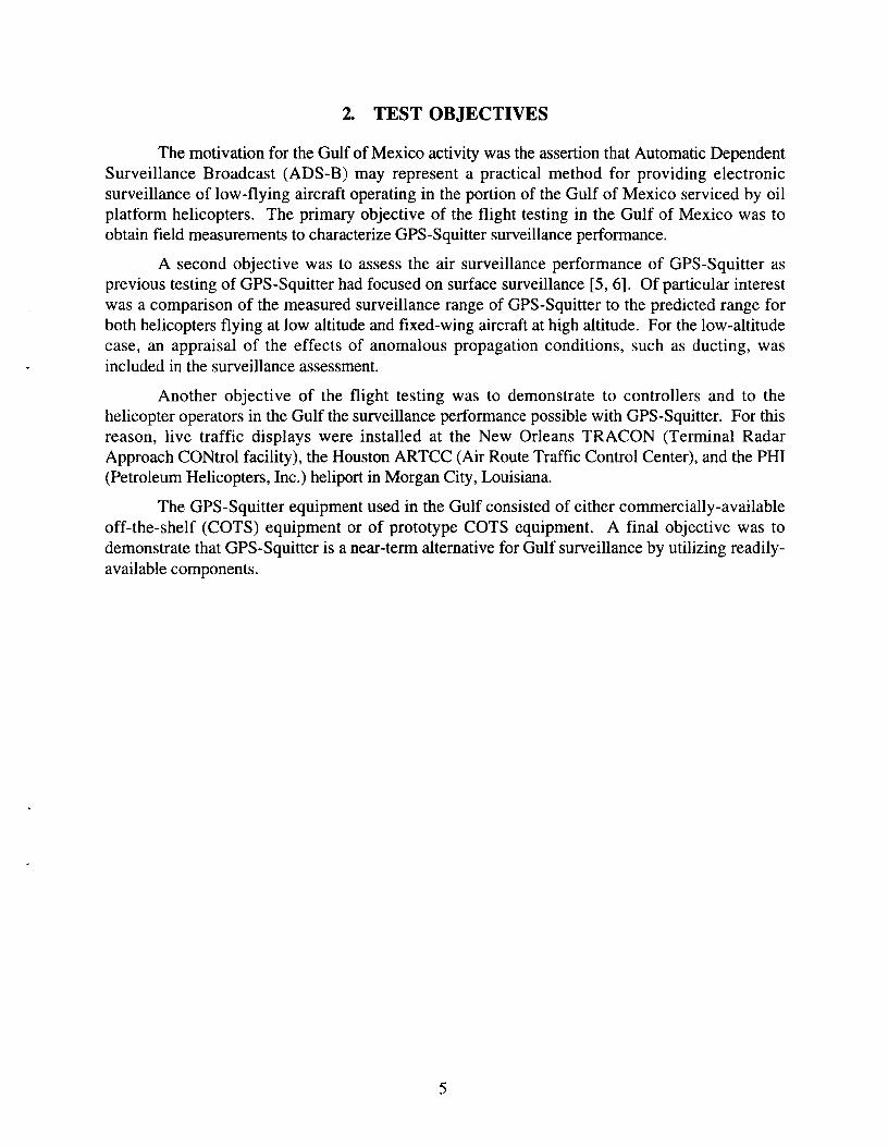
Figure 3-9 shows the link from the SMI 268 ground station to the CCC. PetroComoperates a cellular telephone network in the Gulf of Mexico, and uses satellite links to connect thecellular ground stations on oil platfonns, including the platfonn in SMI 268, to their cellularswitching office in New Orleans. The SMI 268 ADS-B ground station used an existing satellitedigital channel to connect the oil platform to PetroCom's New Orleans facility. Dial-up modemsprovided the last part of the connection to the CCC at Pill over the PSTN. The digital channel onthe PetroCom satellite terminal equipment at SMI 268 and at New Orleans was synchronousRS-232. PetroCom provided RS-232 async to sync converters to generate a baud rate clock and toresample and synchronize the async data to this clock. The async to sync converter is wired asRS-232 DTE device on the sync side, and RS-232 DCE device on the async side. The satellitedigital channels were DCE devices, so the synchronous sides of the sync to async converters wereconnected directly to the satellite channels. On SMI 268, the ground station, being a DTE device,connected directly to the asynchronous side of the sync to async converter. However, at thePetroCom New Orleans facility, a null modem was required to connect the two DCE devices,modem and asynchronous side of the sync to async converter. Like the connection to EI 100, thecommunications link from SMI 268 to the CCC had an RS-232 switch box at Pill, so that the datacould be ignored in case of a CCC software failure.
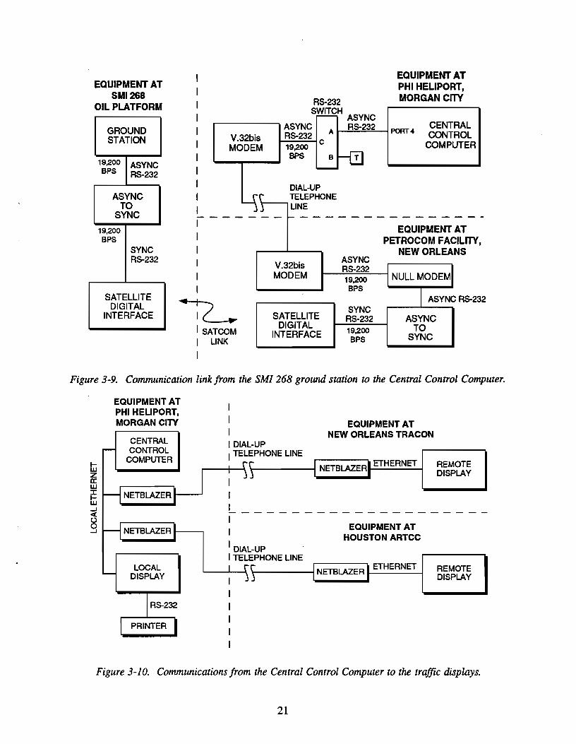
The CCC provided traffic data to displays in Morgan City, New Orleans, and Houston.Figure 3-10 shows the connections from the CCC to the local and remote display computers. Thelocal display computer also acted as the data analysis computer, and had a printer attached to it forlocal hard copy of aircraft track plots and other analysis printouts. The CCC communicated withthe local display in Morgan City via a direct Ethernet Local Area Network (LAN). This sameEthernet LAN also connected the CCC to two NetBlazer PN network devices with internalmodems. The NetBlazer PN converted TCPIIP packets on the LAN to data packets that are sentvia dial-up modem to a remote NetBlazer, which then converted the modem data back to TCPIIPpackets on a second LAN. This capability allowed software on distant computers to transfer dataas if the computers were physically connected to a common LAN. One NetBlazer connected theCCC to a display computer in the New Orleans TRACON; a second NetBlazer connected the CCCto a display computer in the Houston ARTCC.
Two voice communications systems were used during Gulf flight tests. When theWiggins Bell 206 was within 10 nmi of the Pill heliport, the test director at PHI talked to the piloton a special VHF aircraft voice frequency assigned to Lincoln Laboratory for the test. A basestation VHF radio was installed next to the CCC at the PHI facility for the test director's use. Thetest director also communicated with the Cessna 421 on this special frequency. Communicationswith the Cessna 421 extended out to approximately 70 nmi, because the aircraft flew at higheraltitudes than did the helicopter. All communications with the PHI Bell 206 and with the WigginsBell 206 beyond 10 nmi used the PHI voice radio communications network that allowed PHIflight following personnel to talk to aircraft in the Gulf.
20
CENTRALCONTROL
COMPUTER
ASYNCTO
SYNC
EQUIPMENT ATPHI HELIPORT,MORGAN CITY
PORT 4
EQUIPMENT ATPETROCOM FACILITY,
NEW ORLEANS
T
19,200BPS
SYNCRS-232
19,200BPS
ASYNCRS-232
B
R5-232
SWITCH ASYNC
ASYNC A R5-232RS-232 c19,200BPS
V.32bisMODEM
SATELLITEDIGITAL
INTERFACE
DIAL·UPTELEPHONE
\---L1NE
V.32bisMODEM
12 ~I SATCOMI LINK
I
IIIIIIIIIII-------IIIIII
-'1
EQUIPMENT ATSMI268
OIL PLATFORM
GROUNDSTATION
19,200 ASYNCBPS R5-232
ASYNCTO
SYNC
19,200BPS
SYNCR5-232
SATELLITEDIGITAL
INTERFACE
Figure 3-9. Communication link from the SMI 268 ground station to the Central Control Computer.
REMOTEDISPLAY
EQUIPMENT ATHOUSTON ARTCC
EQUIPMENT ATNEW ORLEANS TRACON
III---------------------II
I DIAL-UPI TELEPHONE LINE
IIII DIAL-UPI TELEPHONE LINE
r----+----\ \--------1 NETBLAZER ETHERNET
CENTRALCONTROL
COMPUTER
NETBLAZER t-----'
NETBLAZER t------,
EQUIPMENT ATPHI HEUPORT,MORGAN CITY
tLiza:wiEw-I
§
LOCALDISPLAY
'------'-----\ \-- --j NETBLAZER ETHERNET REMOTEDISPLAY
Figure 3-10. Communications from the Central Control Computer to the traffic displays.
21

3.2.3 Displays
One of the objectives of the testing was to demonstrate to the controllers and to the Gulfhelicopter operators the quality of the GPS-Squitter surveillance. The traffic displays installed atthe PHI heliport in Morgan City, at the New Orleans TRACON, and at the Houston ARTCCprovided a means to display traffic data in real-time, and also to playback recorded traffic data. Anexample of the data available on the display is shown in Figure 3-11.
All three of the test aircraft appear in Figure 3-11. A symbol represents the location of anaircraft and a data tag provides information regarding the aircraft. The top line of the tag is theICAO identification which is received in the extended squitter identification message. For theaircraft in Figure 3-11, the ICAO identification is the aircraft's tail number. The bottom line of thetag contains altitude followed by ground speed. As is the case with typical ATC (Air TrafficControl) displays, altitude and ground speed are given in hundreds of feet and tens of knots,respectively. The displayed altitude is based on the barometric altitude field in the extended squitterposition messages. The values received in the squitter messages were adjusted using the samebarometric pressure corrections applied at the New Orleans TRACON. The final block in the datatag, ground speed, is calculated by the CCC based simply on the change of aircraft position withtime.
The locations of the test aircraft shown in Figure 3-11 are superimposed on a backgroundmap of the area. This electronic map included the Gulf coastline, major roads, and symbolsindicating the location of the three ground stations. Also included were the locations of the nearbyVORs as well as the VOR radials typically flown during IFR conditions. The VORs were WhiteLake (LLA) and Tibby (TBD).
3.3 COMMUNICATIONS PERFORMANCE ISSUES
There were occasional problems with the communications links to the ADS-B groundstations on EI 100 and SMI 268. The problem with the EI 100 link was the mismatch betweenthe dial-up modems and the microwave link back to shore. The problem with the SMI 268 linkwas the corruption of squitter data being sent from the ground station to the CCC, and theinadequacy of the data and checksum protocol, implemented for the Logan Airport tests, whenused over a satellite data link.
On El 100, the microwave link provided a PSTN telephone connection for the Fastcommmodem. However, the telephone signaling levels were not well matched between the microwavelink and the modem, and the occasional dropouts and other perturbations in the microwave linkwould cause the dial-up modem to detect a line failure, and to hang up. The Sun software in theground station, detecting the loss of carrier from the modem, would automatically exit and shutdown. Also, the microwave link was not suitable for the full speed V.32bis modulation(14,400 bps) of the Fastcomm FDX-9642T. To have a modem connection that lasted longer than10 minutes, the originating modem on EI 100 had to be instructed to use a lower baud rate(4800 bps) over the telephone line. This lower data rate was acceptable during the testing in theGulf.
22

Figure 3-11. Traffic display showing test targets, VOR radials, ground station locations,Gulf coastline, and major roads.

The best solution to the microwave problem is to use dedicated, leased line modems on themicrowave link. The communications technicians from Shell report that they use the microwavelink with leased line modems, and that the modem links are reliable. A hybrid connection, withleased line modems from the oil platform to shore, and dial-up modems on the .PSTN from themicrowave shore terminal to the CCC site, would most probably offer a robust link.
On SMI 268, the link from the oil platform to the shore is a data channel on the satellitelink PetroCom uses primarily to handle cellular telephone voice channels. The data channel was asynchronous-only device, so the async to sync converters were installed to convert async RS-232to sync RS-232, and vice versa. During a typical test, the data stream from the SMI 268 groundstation would have 50 to 100 packets per hour fail the checksum test, because the data was beingcorrupted either by the satcom link or by the async to sync converters. Data packets that failed thechecksum test were discarded, as there was neither error correction or retransmission of erroneousdata packets. Also, the modem connection from New Orleans to PHI would occasionally fail,most probably due to intermittent problems on the PSTN.
As a result of the SMI communciations link problems, the software in the CCC had to beimproved several times to make the serial input task more robust in the face of corrupted data.Previously, at the Logan Airport site, three of the ground station communications links usedFastcomm FDX-9642T modems over the PSTN; the fourth link used a spread spectrum radiodata link. All of these links were inherently very reliable, so a simple checksum system wasimplemented to protect against the occasional bad bit. In the Gulf, the bad bits happened sofrequently, and in so many unexpected ways, that the original software was unable to performreliably. New software tests were devised to overcome some of the problems. These testsimproved the error handling capability of the CCC so that it could recognize and reject the 2percent to 3 percent of message packets that were corrupted. However, one difficulty that wasimpossible to overcome was the use of a variable length binary data packet format between theground station and the CCc. The variable length format made it impossible to locate thechecksum byte without first having to read several bytes in the message to determine its length. Ifthe length bytes were corrupted, the CCC improperly processed the serial stream, and wouldoccasionally fail. Also, since the data were binary, it was impossible to scan for a header byte todelimit one message packet from another, as a data byte may have the same bit pattern as a headerbyte.
Should this system be used operationally, a more robust, standard communicationsprotocol should be used such as synchronous RS-232 serial link with High-Level Data LinkControl (HDLC) link level protocol for ground station to CCC communications. SynchronousRS-232 provides a slightly higher data throughput and does not require async to sync converterson the satellite channel, and HDLC on a sync serial link is a bit oriented protocol that includes eightbit flags at the start and end of the data packet and a sixteen bit Frame Check Sequence (FCS)located immediately before the end flag. The HDLC protocol includes a feature that inserts bits inthe data stream to ensure that no consecutive eight bits inside the packet matches the eight bit flag.This scheme allows the HDLC receiver to locate the flag at the end of the packet, and then verifythe FCS without having to use any data bits to determine message length. Additionally, an HDLClink can be configured to acknowledge each message, so that messages that are received witherrors can be retransmitted if desired. A more complete description of HDLC can be found inISOIIEC 3309 [7].
25

4. PREDICTED COVERAGE
Each ground station's maximum coverage range is reached when the signal strength at thereceiver becomes too weak to reliably maintain link connectivity. This happens, for line-of-sightlinks, when the range becomes too great for the transmitter's effective radiated power, or when thesurface-bounce signal effectively cancels the direct signal. It also happens when the increasingrange of the aircraft takes it below the radio horizon of the ground station.
For the two ground stations installed on oil platforms, the multipath bounce point is alwayson the water surface. In this case, a good approximation for the reflection coefficient magnitude is-1.0. That is because, at the low elevation angles which are of principal interest here, the signal isreflected with very little loss of strength, and with a 1800 phase reversal, independently of both thepolarization and whether the water surface is rough or smooth [8]. The reflection geometry isspecular.
Thus, for these ground stations, a good estimate of the received signal is that it is the sumof the direct signal and the multipath signal. The level of the direct signal is the same as it wouldbe in free space, taking account of any antenna directivity at each end of the link. Since there is nosignificant reflection loss, and since the multipath range is not significantly different from the directrange, the multipath signal differs in amplitude from the direct signal only by the amount bywhich, at each end of the link, the antenna gain in the multipath-signal direction differs from that inthe direct-signal direction. The phase difference between the two signals is precisely the electricalpath length difference between the two, expressed in degrees, augmented by the further 1800
surface-reflection reversal. Of course, every inch of range difference between the two paths issignificant for the calculation of phase difference.
For the ground station on land, however, the multipath bounce point is always on the land,which, for the PHI ground station, is wooded. A good approximation for the reflection coefficienthere is that it is zero. That is because the reflection from the tree tops is diffuse rather thanspecular, which means that the level of the reflected signal, at the receiver, is negligible comparedwith that of the direct signal. In this case, the only significant contribution at the receiver is that ofthe direct signal. Its amplitude, as long as the line of sight is clearly unobstructed, is equal to thefree space amplitude. As the line of sight drops toward the tree tops, however, the signal will fadesteadily away, reaching a level of essentially zero when the elevation angle reaches zero. (Thepoint at which the effect of the horizon first begins to be significant is when it encroaches on thefirst Fresnel zone. The Fresnel zone is the ellipsoid whose foci are at the two terminals and whosesurface is defined by the locus of points whose distances from the foci, when summed, are a halfwavelength longer than the inter-focal distance.)
Finally, there is an adjustment to the model that needs to be applied at all three groundstations. This is the adjustment to the effective earth radius to account for atmospheric refraction.In average weather conditions, the refractive index of the atmosphere decreases as a function ofheight. This causes the signal path at radio frequencies to curve slightly toward the earth; in effect,it moves the radio horizon further away than the optical one. The standard way of accounting forthis effect is to retain the assumption that the signal paths are straight but use for the radius of theearth a distance that is greater than the true value by 33.3%. This is known as the four-thirds earthradius model.
27

Figures 4-1 to 4-3 are representative examples of the result of applying these principles toestimate the link margin as a function of range for the three ground stations. Figure 4-1, in whichthe aircraft flies at a constant altitude of 2000 ft, applies to one of the many scenarios included inthe demonstration. For the PHI ground station, whose antenna is directional in azimuth, the curveapplies to the 100° wide sector defined by the flat top of the azimuth beam shape. In addition,since the horizon for the PHI ground station is defined by the tree tops, the antenna height and theaircraft altitude used in the calculations were both 40 ft less than their values (90 and 2000 ft)referred to the surface. Table 4-1 lists the assumed values for the other link budget items involvedin preparing these figures.
Table 4·1
Link Budget Items
Transmit Power (W) 200
Transmit antenna gain (dB) 0
Receive antenna gain (dB) 10 (land), 8 (platform)
Cable 1055 (dB) 3
Receiver detection threshold (dBm) -82.5
In interpreting the curves, one needs to bear in mind that the refractive properties ofatmosphere and the sea surface are constantly changing, so the assumptions on which thepropagation model is based are neither precise nor unchanging. This means that the depth andlocation of the multipath nulls will not be stable and that the maximum range will vary.
Some salient features of the curves are:
• For the SMI 268 and EI 100 ground stations, the striking comb-like sequence ofmultipath nulls, which potentially can break the link connectivity. However, at shortranges, the nulls have no serious system impact because they do not maintain theirdepth or position consistently; they are fairly narrow, and the average link margin isgood. The nulls do become a factor at longer ranges since the width of the nullsincrease with range and the average link margin is lower.
• In contrast, a complete absence of nulls for the PHI ground station.
• The greater maximum coverage range of the platform ground stations, in spite oftheir smaller antenna gain. This is due to the combined effects of their greaterantenna height and the periodic signal enhancement by the multipath contribution.
The curves for other aircraft heights are similar to these. The trends in the differences areprincipally that when the aircraft flies higher, the maximum coverage range is greater, and the nulldensity increases.
Extracted from the margin curves is the list of expected maximum coverage ranges shownin Table 4-2. The margin threshold used to define these ranges was the 4 dB level marked on themargin graphs as a dashed line. (This particular value was chosen because a statistical survey ofaircraft antenna gains [9] reported that more than 99 percent of the time the gain of one or other of
28

the two TeAS antennas on an aircraft in level flight, in the direction of the receiver, is greater than-4 dBi.) These estimated maximum coverage ranges are not a perfect demarcation, however. Thepresence of the multipath nulls at shorter ranges will cause the occasional loss of a squitter fromaircraft flying within the maximum coverage range. On the other hand, the high probability of theaircraft antenna gain exceeding the threshold of -4 dBi will lead to squitters being received fromaircraft flying beyond the estimated maximum coverage range. Propagation anomalies can alsolead to enhanced or diminished coverage.
A comparison of the model predictions with the data gathered during the demonstration ispresented in Section 5.4. The conclusion reached there is that the data support the model. That isto say, the propagation model constructed to evaluate the expected performance of thedemonstration surveillance system was shown to be accurate.
It should be noted, however, that this model will need to be adjusted before it can be usedfor the different purpose of designing a surveillance system for highly reliable year-roundoperation. It must take into account the additional uncertainties of aircraft transmitter power outputand anomalous propagation. The effect of the latter are discussed in the Appendix. Certain systemparameters are identified there which should be set appropriately to achieve reliable operation.
AIRCRAFT ALTITUDE 2000 ft
80
4 dB threshold
60
PHI GROUND STATIONANTENNA HEIGHT 90 ftPEAK GAIN 10 dBi
\\\\\\\\\\\\
40
EI & SMI GROUND STATIONSANTENNA HEIGHT 160ftPEAK GAIN 8 dBi
20
o
-20 L----'-_-'----'-_....I..-----'_-'-_'----L._..a....L..---'-_....L...----1_-'-.....l.-'-----'-_
o
co"C 20--
RANGE (nmi)
Figure 4-1. Ground station link margin for an aircraft at 2000-ft altitude.
29

PHI GROUND STATIONANTENNA HEIGHT 90 ftPEAK GAIN 10 dBi
I
4 dB threshold
-"--"-
-"- '- I"- .
- I------~----~----
\ I\ i
\Jj;\\\\
AIRCRAFT ALTITUDE 300 ft
EI & SMI GROUND STATIONSANTENNA HEIGHT 160 ftPEAK GAIN 8 dBi
o
20
40302010
-20 '------'----'----'---'--..L-----''--"'---"''''-----'---'----'------'_"''''---....I...-....L.---'-----'-..........._L.....-...J
o
RANGE (nmi)
Figure 4-2. Ground station link margin for an aircraft at 300-ft altitude.
40 ,....-....-----.--..---.----,--r--..,----.---,-----,-,....--.----.---.----r-.....-....----.---..----,
AIRCRAFT ALTITUDE 20,000 ft
EI &SMI GROUND STATIONSANTENNA HEIGHT 160 ftPEAK GAIN 8 dBi
20PHI GROUND STATIONANTENNA HEIGHT 90 ftPEAK GAIN 10 dBi
o
\\\.\
20015010050
-20 L-....I...---'-----'----'-----J'------'----'----'----'----l_"'---"""-----'---I...---l.l...-.....u........I...-L......-.l....L..---J
o
RANGE (nmi)
Figure 4-3. Ground station link margin for an aircraft at 20,000-jt altitude.
30

Table 4-2
Predicted Ground Station Surveillance Range With a 4 dB Link Margin
Maximum coverage range (nmi)
Aircraft altitude (ft) PHI SMI268 & EI100
100 11 21
300 20 30
600 28 38
2,000 50 62
5,000 78 92
7,500 94 110
20,000 100 136
31

5.' FLIGHT TEST RESULTS
During November and December 1994, GPS-Squitter flight tests were conducted in theGulf of Mexico. The three test aircraft described in Section 3.1 made numerous flights during thisperiod at various altitudes. This section provides results from the flight testing.
5.1 WIGGINS BELL 206 HELICOPTER
Flight tests with the Wiggins Bell 206 helicopter were designed to assess the surveillancecoverage between the PHI ground station and each of the offshore ground stations. The WigginsBell 206 flew from the PHI heliport to the SMI 268 and EI 100 platforms at altitudes of 100, 300,and 2000 ft. The lowest altitude flown, 100 ft, is well below the minimum en route VFR altitudeused in the Gulf; the highest altitude, 2000 ft, represents an upper bound on the altitudes typicallyflown during VFR conditions. The ground stations were sited to provide continuous surveillanceof helicopters flying between the stations at 300-ft altitude or higher. The results from flights at300 ft demonstrated that this was indeed the case.
The antenna pattern of the transponder antenna on the Bell 206 did have an affect on thesurveillance performance during the flight testing. A short discussion on the antenna pattern is,therefore, provided before the flight test results for the helicopter are presented.
5.1.1 Transponder Antenna Pattern
The transponder antenna for the Wiggins Bell 206 is mounted on the underside(Figure 5-1), the standard location for transponder antennas on helicopters. There are many otherobjects mounted on the Bell 206's underside including: the helicopter's skids, other antennas, and ametal tank containing compressed gas (for inflating the floats that are tied to the skids). All ofthese objects affect the transponder's antenna pattern.
Prior to deploying the helicopter to the Gulf, a test was conducted at Hanscom Field inBedford, Massachusetts, to measure the antenna pattern. During this test, the helicopter performedseveral pedal turns as it hovered over a fixed location. A device known as the AirborneMeasurements Facility (AMP) [10] was used to record the amplitude of the extended squittersradiated by the transponder antenna. The AMP was located at surface level and the elevation angleto the helicopter was approximately 3 degrees. The variations in received amplitude as thehelicopter turned were used to determine the relative gain of the transponder antenna as a functionof look angle. A plot of the antenna pattern is shown in Figure 5-2.
The antenna pattern contains nulls in certain directions. In particular, there is a substantialnull (approximately 20 dB below isotropic, i.e., -20 dBi) near the tail of the helicopter possiblycaused by the metal tank mounted just behind the transponder antenna. Near the front of theaircraft and near broadside the gain of the antenna is fairly good.
33

Figure 5-1. Transponder antenna mounted on the underside of the Wiggins Bell 206 helicopter.
35

5.1.2 Flights at 100-ft Altitude
For flights at 100-ft altitude, the Wiggins Bell 206 flew directly from the PHI heliport tothe offshore ground station sites and back. Near each platform, the Bell 206 hovered at the landingpad level (approximately 50 ft above the water) before returning to the PHI heliport. The WigginsBell 206 was equipped with a radar altimeter that was used to maintain an altitude of 100 ft asmuch as possible. However, some deviations from the 100 ft level were necessary, especiallyover land.
The results of a flight from the PHI heliport to SMI 268 are shown in Figure 5-3. Thisfigure is divided into four plots-the first three, Figures 5-3a, 5-3b, and 5-3c, show the individualcoverage from the ground stations at PHI, SMI 268, and EI 100, respectively. The fourth plot,Figure 5-3d, shows the combined coverage from all three stations.
+10 ..,......-------~~-r-~~-------.....,
o
-10
-10
RELATIVE ANTENNA GAIN (dBi)
o +10
Figure 5-2. Antenna pattern for the Wiggins Bell 206 transponder antenna.
37

(a)o
-10
-"e.sJ:...:;)0
-20({2J:...a:0z
-30
SURVEILLANCE FROM PHIHELICOPTER ALTITUDE 100 ft
~,
~ ~-"-', L~~
""'~~~--~(
SMI268I'l EI100
o-10-30 -20EASTIWEST (nmi)
-40-40 L.-_--'-- '--_....l...-_----'-_----...l__--'--_---'-_------'__...L-_---l
-50
(b)o
-10
-"E.sJ:...:;)
o -20~...a:oz
-30
SURVEILLANCE FROM SMI 268HELICOPTER ALTITUDE 100 ftr '~',-,
'''~'~~f~( (~J
P..----
SMI268I'l EI100
o-10-40-40 '--_--'--_----'-__'--_--'--_----'-_-----l__--'--_----'-_-----l__--'--_---l
-50 ·30 -20EASTIWEST (nmi)
Figure 5-3a-b. GPS-Squitter surveillance of the Wiggins Bell 206, during a flight to SMI 268 at100-ft altitude, from the ground station at (a) PHI and (b) SMI268.
38

-30
::2:...::::>o~ -20
...0::oZ
(c)
:::Er::-
o
-10
SURVEILLANCE FROM EI 100HELICOPTER ALTITUDE 100ft
"
o EI100
o-10-30 -20EASTIWEST (nmi)
-40-40 L....--_----'--_-----l__---'--_----l-__-'--_--L__"'--_--l-_-----"~_ ___l..___
-50
Figure 5-3c. GPS-Squitter surveillance ofthe Wiggins Bell 206, during a flight to SMI 268 at100-ft altitude, from the ground station at EI 100.
39

o
-10
-Ec-::J:I::)
ose -20::J:l-e:oz
-30
-40-50
UPDATE RATE• 0 - 5 seco 5 - 10 sec, > 10 sec
SMI268
-40
til EI100
-30 -20EASTIWEST (nmi)
-10 o
Figure 5-3d. GPS-Squitter surveillance of the Wiggins Bell 206, during a flight to SMI268at 100-ft altitude, from the three ground stations combined.

In Figure 5-3a, an arc is drawn at a radius of 11 nmi from the PHI ground station. This isthe predicted coverage range for an aircraft at l00-ft altitude for this ground station as explained inSection 4. Similarly, arcs at a radius of 21 nmi from the SMI 268 and EI 100 ground stations areshown in Figure 5-3b and 5-3c. This represents the predicted range for the offshore groundstations. For the PHI and SMI 268 cases, the agreement between the predicted and actual coverageis, in general, quite good. There is, however, an imbalance between the coverage of the helicopterwhen it was flying toward SMI 268 versus flying away from this ground station. When flyingtoward SMI 268, a solid track was initiated at 25-nmi range, and in the other direction the solidtrack was lost at -20-nmi range. This probably is due to variations in the antenna pattern for thehelicopter's transponder. As shown in Figure 5-2, there is a null in the pattern near the tail of thehelicopter while no similar null exists near the front section.
The EI 100 ground station performed slightly better than predicted during the flight. Asolid track was obtained when the helicopter was within 25 to 27 nmi of EI 100 versus thepredicted range of 21 mni (Figure 5-3c). The difference could be due to the fact that the antennapattern for the helicopter has increased gain near both the port and starboard broadside locations.
Different symbols are used in the combined coverage plot of Figure 5-3d. These symbolsprovide an indication of the surveillance update rate attained during the flight. A small solid dot isused to represent a position update that was received within 5 sec of the previous update; a squareis used for updates that were received 5 to 10 sec apart; and an X is used to represent an update thatwas received more than 10 sec after the preceding one. For comparison, terminal area surveillanceradars typically provide and update rate of once per 5 sec and en route radars provide an update rateof 10-12 sec.
There is a 5-10 nmi wide coverage gap between the SMI 268 and PHI locations. This isnot surprising since the siting of the stations was chosen to provide continuous surveillance ataltitudes of 300 ft and above. The gap is due to the radar horizon limitation and can be overcomeby either reducing the spacing of the ground stations or by increasing the antenna height of theground stations (the latter solution is feasible for onshore stations, but would be difficult for theoffshore sites).
Figure 5-4 shows results from a flight taken with the Wiggins Bell 206 from the PHI tothe EI 100 ground station. The results are presented in the same manner as those in Figure 5-3.The coverage from the PHI ground station in Figure 5-4a was slightly greater than the predictedcoverage. On occasion, the Bell 206 flew at an altitude somewhat above 100 ft during the overlandportion of its flight because of buildings and other obstructions in the area. This would account forthe increased range. No surveillance coverage was predicted from the SMI 268 ground station forthis flight but there was a small amount of coverage just beyond the predicted coverage limit of21 nmi. The agreement between the predicted and actual coverage for the EI 100 ground stationwas excellent, with the slightly greater range obtained as the helicopter flew toward EI 100explained by the variations in the antenna pattern for the transponder. As was the case for theflight at 100-ft altitude to SMI 268, there is a coverage gap in the combined surveillance plotshown in Figure 5Ad.
41

5.1.3 Flights at 300-ft Altitude
Flights from the PHI heliport to each of the offshore ground station locations were alsoperformed at 300-ft altitude. Again the helicopters hovered at landing pad level near each platformbefore returning to PHI. Figure 5-5 indicates the surveillance during the flights to SMI 268 andEI 100. These flights were performed on different days, but the results have been combined in thefigure. The surveillance during both flights was excellent-throughout each flight, surveillanceupdates were received at a rate of once per 5 sec or better.
5.1.4 Flight at 2000-ft Altitude
One coverage flight with the Wiggins Bell 206 helicopter was performed at 2000-ftaltitude. During this flight the helicopter flew from the PHI heliport to EI 100 and back. Thecombined surveillance coverage is shown in Figure 5-6. Again the surveillance performance wasexcellent with once per 5-sec updates received throughout the flight. Additional flights at2000-ft altitude were flown to SMI 268 to assess possible effects of anomalous propagation, andthese are described in the Appendix.
Prior to the testing, flights to each offshore platform at 5000 ft had been planned.However, because of the excellent results obtained during the flights at 300- and 2000-ft altitude,these additional flights were canceled since it was clear that they would also indicate continuoussurveillance coverage.
42

(a) 4
0 SURVEILLANCE FROM PHIHELICOPTER ALTITlIDE 100 ft
-~ 1~ -----./ - ~
~\_~?;I ~~J r''>
-10 '~.......'E.s:I:to-~
0 -20(Q:I:to-II:0z
-30
!l
SMI268!l EI100
-40-50 -40 -30 -20 -10 0
EASTIWEST (nmi)
(b) o
-10.......'E.s:I:to~o(Q -20:I:to-II:oZ
·30
SURVEILLANCE FROM SMI 268'~ HELICOPTER ALTITUDE 100 ft
~_~~7
21 nmi
\
P••----
!l
SMI268
/
IlEI 100
o-10-40-40 '--_--'---_----'-_-----'__-'--_-.L-_----'-__-'--_--'-_-'-__-'--_---l
-50
Figure 5-4a-b. GPS-Squitter surveillance of the Wiggins Bell 206, during a flight to EI 100 atIOOjt altitude,jrom the ground station at (a) PHI and (b) SMI268.
43

(c)o
-10
-'Er::-
SURVEILLANCE FROM EI100HELICOPTER ALTITUDE 100 ft
,--:::",~ ~
,/ ~
~. ~.~
::E:....;:)aS!! -20::E:....0:az
·30
o
SMI268
o·10·30 ·20EASTIWEST (nmi)
-40.40 L-_----'-_-----J__--'--_-----l.__-'--_----L__-'--_---L__.L--_---l.-_--l
·50
Figure 5-4c. GPS-Squitter surveillance of the Wiggins Bell 206, during aflight to EI 100 at100-ft altitude, from the ground station at EI 100.
44

o
·10
::Ec-
COMBINED SURVEILLANCEHELICOPTER ALTITUDE 100 ft
/'~ -~
\~
~~~
::E:I;j
o~ ·20::E:Ia:oz
·30
UPDATE RATE• 0 - 5 seco 5 - 10 sec, > 10 sec
SMI268
o-10-30 -20EASTIWEST (nmi)
-40.40 l--_----'-__....l....-__'---_---L.__--'--__...L...-_----l.__---L-__....L..-__'---_----l
-50
Figure 5-4d. GPS-Squitter surveillance of the Wiggins Bell 206, during aflight to EI100at 100-ft altitude, from the three ground stations combined.

o COMBINED SURVEILLANCEHELICOPTER ALTITUDE 300 ft
-10
==-Ec-:::E: UPDATE RATEI-::::) • 0 - 5 sec0 -20 o 5 - 10 sec~ ~0\:::E: ' > 10 secI-a::
R0z
""--30
o-10-30 -20EAST/WEST (nmi)
-40-40 L-_----L..__....l-_----L__.-L.-__.L....-_----1.__--'--__L..-_----L..__....L-_-----I
-50
Figure 5-5. Combined GPS-Squitter surveillance of the Wiggins Bell 206 during flightsto SMI 268 and £1 100 at 300-ft altitude.

o-10-30 -20EASTIWEST (nmi)
-40
SMI268
-40 "---_--'-__.....J...-__J......-_---'-__----'--__...L...-_----'__----'-__.....J...-__J......-_----'
-50
0 COMBINED SURVEILLANCE
<?:50PTER~~2000 ft -, is-10 ~-~~( ~
:=-El::-
~J: UPDATE RATEI-~ • 0 - 5 sec0
;:\;~~~ en -20 o5-10sec'-l -J: . > 10 secI-
a:
~-~~c(0z
-30
Figure 5-6. Combined GPS-Squitter surveillance of the Wiggins Bell 206 during flightsto EI 100 at 2000-ft altitude.
5.2 PHI BELL 206 HELICOPTER
The second helicopter equipped with GPS-Squitter was an in-service helicopter operated byPHI. This PHI Bell 206 served as a target of opportunity during the testing. The PHI Bell 206was based at the PHI heliport in Morgan City and was often within surveillance coverage of theGPS-Squitter ground stations.
An example of the surveillance coverage of the PHI Bell 206 is shown in Figure 5-7.When data recording was turned on that day, the PHI helicopter was airborne and approximately10 mni north of EI 100. The helicopter then flew toward the southwest to an oil platform beyondthe surveillance coverage, returned to the Shell heliport near Morgan City, and then flew to aplatform in Eugene Island Block 158 (EI 158) before returning again to the Shell heliport. Whileen route, the helicopter flew at altitudes of 500-700 ft.
Solid surveillance coverage of the PHI helicopter was achieved with the exception of whenit flew south of the coverage area. The range at which surveillance was lost during this portion ofthe flight, 35-40 nmi, is consistent with the predicted range for a helicopter flying at 500-700 ftaltitude. During the remainder of the flight, the surveillance update rate was once per 5 sec orbetter-including the period when the helicopter was on the landing pad at EI 158.
5.3 CESSNA 421 FIXED-WING AIRPLANE
Several flight tests were conducted with a Cessna 421 aircraft. Two of these were longrange flights during which the Cessna flew toward the west-once at 20,000-ft altitude and once at7500-ft altitude. The remaining flights with the Cessna followed various radials from the WhiteLake and Tibby VOR installations. The long range flights were designed to measure the highaltitude surveillance range of the ground stations over the Gulf. Flights along VOR radialsmeasured the surveillance coverage for the flight paths followed during IFR conditions in the Gulf.
5.3.1 Long Range Flight at 20,000-ft Altitude
For the flight at 20,000-ft altitude, the Cessna 421 departed from Williams Memorial Fieldin Patterson, Louisiana, and flew to a point -40 mni west of the Sholes VOR in Galveston, Texas,before returning to Williams Field. Unlike the two helicopters which only have bottom-mountedtransponder antennas, the Cessna is equipped with two antennas. One antenna is mounted on thebottom of the airframe and the other on top. Both antennas were enabled during the flight and theextended squitter transmissions alternated between the two antennas.
The surveillance coverage during the flight tests are shown in Figure 5-8. The four plots inthis figure indicate coverage from each of the individual ground stations as well as the combinedcoverage. During the tests, the strength of the extended squitter transmissions was expected tovary based on range to a ground station and on the effects of ground bounce multipath. The latteris especially true for the two oil platform ground stations because, for each of these, the groundbounce was off the highly reflective Gulf water. Figure 4-3 shows the expected variation inreceived signal strength as a function of range for this case (an aircraft at 20,OOO-ft altitude).
48

0 COMBINED SURVEILLANCE
';~~jHELICOPTER ALTITUDE 500-700 ft~~
~ SHELL HELIPORT
START OF DATA
~C;~~~)-20
RECORDING '"-'Sc- UPDATE RATE
~
::I:I-
o 0 - 5 sec::J0
o 5 - 10 sec SMI268 ~
~ en -40 EI100\0 -::I: ' > 10 secI-a:0z
LANDED AT EI158-60
-80 L----.L-_-1.__....l.-_-----'L.-_----L...__...I....-_----'-__--'----_--'__---'--__.J..-----J
-80 -60 -40 -20EASTIWEST (nmi)
o 20
Figure 5-1. Combined GPS-Squitter surveillance of the PHI Bell 206.

60SURVEILLANCE FROM PHIC421 ALTITUDE 20,000 ft
:=-Ec:-:J:...::J0en
VI -0 :J:I-a:0z
20
-20
-60
-100
UPDATE RATE• 0 - 5 seco 5 - 10 sec, > 10 sec
SMI268• •
EI100
-240 -200 ·160 -120 ·80EASTIWEST (nmi)
-40 o
Figure 5-8a. GPS-Squitter surveillance of the Cessna 421, during a long range flight at20,OOO-jt altitude, from the ground station at PHI.
60SURVEILLANCE FROM SMI 268C421 ALTITUDE 20,000 ft
:=-Ec-~I-
VI ::J.- 0en-~
I-a:0z
20
·20
·60
·100
UPDATE RATE• 0 - 5 seco 5 - 10 sec, > 10 sec
ATTERSON
1PHI
~
•EI100
·240 ·200 ·160 ·120 ·80EASTIWEST (nmi)
·40 o
Figure 5-8b. GPS-Squitter surveillance ofthe Cessna 421, during a long range flight at20,OOO-jt altitude, from the ground station at SMI268.

60SURVEILLANCE FROM EI 100C421 ALTITUDE 20,000 ft
-Ec-::r~~
Vl 0N ~
::r~a:0z
20
-20
-60
-100
UPDATE RATE• 0-5 seco 5 - 10 sec, > 10 sec
SMI268• •
EI100
-240 -200 -160 -120 -80EASTIWEST (nmi)
-40 o
Figure 5-8c. GPS-Squitter surveillance of the Cessna 421, during a long range flight at20,000-ft altitude, from the ground station at EI 100.

o-40-160 -120 -80EAST/WEST (nmi)
-200
COMBINED SURVEILLANCEC421 ALTITUDE 20,000 ft
-240
60
20
-E --c ---- -::z::: ---I- -20:;)
0 SMI268tn •-VI ::z::: •w I- EI100a:0z -60
UPDATE RATE• 0 - 5 sec05- 10 secx > 10 sec
-100
Figure 5-8d. GPS-Squitter surveillance of the Cessna 421, during a long range flight at20,OOO-jt altitude, from the three ground stations combined.

The effects of ground bounce multipath are clearly visible in Figures 5-8b and 5-8c. Nearthe offshore ground stations, the link margin is sufficient to overcome the nulls caused bymultipath reflections. However, at longer ranges there are gaps in the surveillance coverage andthese gaps become wider with increasing range. The locations of multipath nulls do not agreeexactly with Figure 4-3, but the overall pattern does agree. As expected, there is less evidence ofmultipath in Figure 5-8a which shows coverage from the PHI ground station (there are trees alongthe PHI path, which would tend to diffuse the reflected signal). The spatial diversity of the groundstations helped to fill in the coverage gaps for the individual ground stations as shown in combinedcoverage plot of Figure 5-8d.
Table 5-1 summarizes the surveillance update rate for the ground stations as a function ofrange. The probabilities of obtaining a surveillance update once every 5 sec and once every 10 secare shown for each individual ground station and for the stations combined. Four cases are showncorresponding to ranges of 50, 75, 100, and 125 nmi from the individual ground stations. For thecombined case, the range to the nearest ground station was used. Even though the Cessnaremained at 20,000-ft altitude for most of the flight, it was below this altitude during its ascentfrom and descent to Williams Field. The results in Table 5-1 includes all altitudes above 3000 f1.
Table 5-1
Surveillance During Cessna 421 Flight at 20,OOO-tt Altitude
RANGE Probability of 5-sec Update Probability of 10-sec Update
(nmi) PHI 8MI 268 EI 100 Combined PHI 8MI268 EI 100 Combined
0-50 1.00 0.998 1.00 1.00 1.00 1.00 1.00 1.00
0-75 1.00 0.999 0.998 1.00 1.00 1.00 1.00 1.00
0-100 0.919 0.984 0.971 0.998 0.928 0.987 0.979 1.00
0-125 0.858 0.966 0.919 0.991 0.873 0.973 0.934 0.993
The surveillance to 75 nmi range was solid for all ground stations. A once-per-lO-secsurveillance update (the typical en route update rate) was attained 100% of the time by each groundstation out to this range. Beyond 75 nmi, the reliability started to taper off, but the combinedperformance was still 100% to 100 mni range and 99.3% to 125 nmi.
5.3.2 Long Range Flight at 7500-ft Altitude
The long range flight at 7500-ft altitude followed a similar track to the one described above,i.e., the Cessna 421 departed from Williams Field and flew toward the Sholes VOR beforereturning to Williams Field. Figure 5-9 shows the coverage obtained during this flight for theindividual ground stations as well as the combined coverage. Again the effects of ground bouncemultipath are evident in the coverage plots for the two offshore ground stations (Figure 5-9b and5-9c). Near the radar horizon of -120 nmi, the coverage from the two platforms becomesintermittent before dropping off completely. As was the case in Figure 5-8d, the combinedcoverage plot of Figure 5-9d shows that the ground stations complemented each other quite wellfew gaps in coverage occurred at the same time for all three stations.
54

PHI
20 I
~ SURVEILLANCE FROM PHIC421 ALTITUDE 7500 ft
0 ~-Ec:::- -0-------"
::I: < ..,..--c ~ --I- ~--:;:)-20VI 0
VI en-::I:l-ll: UPDATE RATE0z . 0 - 5 sec
-40o 5 - 10 sec< > 10 sec
SMI268•
PATTERSON
\
['--
•El100
o-20-40-100 -80 -60EASTIWEST (nmi)
-120-140-60 ~L-.L.-.L.-..L.-....L.-....L.-..~...L..---L----'----'----'----'----'-----'-........L..----I-----'----L--'-J'--L.....-L--.L-.L.-...l....-...L..-~--,----'----'----...l...----l
-160
Figure 5-9a. GPS-Squitter surveillance of the Cessna 421, during a long range flight at7500-ft altitude, from the ground station at PHI.

•EI100
•SMI268
UPDATE RATE. 0 - 5 seco 5 - 10 sec, > 10 sec
20,---.-----,-----.-r=~-.-----.-----.--.---.-----.-----,----.-----,------.----,----,----,--,.--,-.--..--.---,------,---.-----.-----.----.-----,-----.----,------.---,tJ SURVEILLANCE FROM SMI 268~" C421 ALTITUDE 7500 fl
0:::-Ec-::I:....~
-200VI ~
::I:0\ ....a:0z
-40
o-20-40-100 -80 -60EASTIWEST (nmi)
-120-140-60 L--_'___'___...l.......___'___--'-----'---_L___L__--'-----'--___'_____'_~__L_____L_____'______L____1____''___L._.L.....__'___'___...l.......___'_____'___L____'_____'_____'_~__L____'
-160
Figure 5-9b. GPS-Squitter surveillance of the Cessna 421, during a long range flight at7500-ft altitude, from the ground station at SM1268.

0::::-Ec-::I:I-::::)
-20Ul 0-...I en-::I:I-a::0z
-40
SURVEILLANCE FROM EI 100C421 ALTITUDE 7500 ft
UPDATE RATE. 0 - 5 seco 5· 10 secx > 10 sec
--
SMI268•
PATTERSON
\
•EI100
-60 L...--L........J............----L----L----L.----L.----L.----L.----L.----'-----'-----L----L----L----L----'-----'-----L----L----L----'-----'-----'-----'-----'-----'----'----'----'----'----'-.......
-160 -140 -120 -100 -80 -60 -40 -20 0EAST/WEST (nmi)
Figure 5-9c. GPS-Squitter surveillance of the Cessna 421, during a long range flight at7500-ft altitude, from the ground station at EI 100.

20
COMBINED SURVEILLANCEC421 ALTITUDE 7500 ft PATTERSON
\0 •
:::-Ec-J:to- .----------.~
-20~,,--«...o(J<:X )+.--0- A
VI 0>f""""O____x.--{)o-
""00 (/)-J:to- SMI268a: UPDATE RATE0 •Z • 0 - 5 sec •
-40o 5 - 10 sec EI100, > 10 sec
-140 -120 -100 -80 -60EAST/WEST (nmi)
-40 -20 o
Figure 5-9d. GPS-Squitter surveillance of the Cessna 421, during a long range flight at7500-ft altitude, from the three ground stations combined.

Table 5-2 summarizes the results for the 7500-ft altitude flight for ranges of 50, 75, and100 nmi. The overall performance was, as predicted, less than that of the 20,000-ft flight, but stillquite good. The combined surveillance provided a probability of a once-per-lO-sec update of100% to a range of 50 nmi and 99.5% to a range of 75 nmi from the nearest ground station. Outto 100 nmi the combined surveillance provided a 98.5% probability of a once-per-l O-sec updateeven though the Cessna was beyond the radar horizon of the PHI and EI 100 ground stations forthe outer portion of this case.
Table 5-2
Surveillance During Cessna 421 Flight at 7500-ft Altitude
RANGE Probability of 5-sec Update Probability of 10-sec Update
(nmi) PHI SMI268 EI 100 Combined PHI SMI 268 EI 100 Combined
0-50 1.00 0.994 0.997 1.00 1.00 1.00 1.00 1.00
0-75 0.969 0.960 0.945 0.995 0.974 0.971 0.958 0.995
0-100 0.897 0.913 0.919 0.980 0.909 0.929 0.936 0.985
5.3.3 Flights Along VOR Radials at 7500-ft Altitude
For several ofthe flight tests, the Cessna 421 followed routes typically taken by helicoptersoperating under IFR. During IFR, helicopters fly along VOR radials until they are near to thedesired platform and then deviate from the radial to the platform (visibility permitting). The IFRflights may occur at altitudes up to -7000 ft. An altitude of 7500 ft was chosen for the Cessna 421as this was the minimum altitude that could be flown without interfering with regular helicopteroperations in the Gulf. For added safety, all of the Cessna's flights were performed during VFRconditions.
Three different flights along VOR radials are depicted in Figure 5-10. In each case, theCessna flew along a Tibby radial until it intercepted one of the White Lake radials and thenfollowed the new radial toward the While Lake VOR. When the Cessna was -10 nmi from WhiteLake it reversed course back to Tibby. Not surprisingly, the surveillance coverage was excellentwithin this region. With only a single exception, one or more surveillance updates were receivedfrom the Cessna every 5 sec during these flights. For the one exception, a surveillance update wasreceived within 10 sec of the previous report.
5.4 COMPARISON OF PREDICTED AND MEASURED PERFORMANCE
Tables 5-3 and 5-4 compare estimated maximum ranges with measured maximum rangesfor various aircraft altitudes. The first table applies to the PHI ground station; the second, to theplatform stations. For the estimates, the maximum range is defined to be the greatest range atwhich the link margin is 4 dB. The agreement shown in the two tables between the estimated andmeasured maximum ranges is generally good. Even the 20,000-ft data for the platform groundstations are consistent with the propagation predictions; note that, according to Figure 4-3, the gapsbetween the link-margin peaks become smaller than the widths of the peaks only when the range is
59

COMBINED SURVEILLANCEC421 ALTITUDE75~
«:?o
-20
--Ec......
""'":I: -40....::J0~:I:....0:0
UPDATE RATEz -60• 0 - 5 secas ·10 sec• > 10 sec
·80
-60-80-1 00 l-_ ___.L__'______ ___.L_~'______ ___.L_~'______ ___.L_~'______ ___.L__L..__ ___l__ ____J
·40 -20 0 20EASTIWEST (nmi)
Figure 5-10. Combined GPS-Squitter surveillance of the Cessna 421 duringflights along 1FR routes at 7500-ft altitude.
60

smaller than about 90 mni. To have the measured link performance described as intermittent atlonger ranges than this is therefore to be expected.
The 20,OOO-ft data for all ground stations display another effect that distinguishes themfrom the lower-altitude data. At the higher aircraft altitudes, the maximum range is limited bysystem sensitivity rather than by horizon blockage. As a result, the general decrease in link margindown past the 4-dB theshold occurs more gradually. And since the threshold is in practicesomewhat fuzzy, the intermittent link closure would be expected to extend over a wide rangeinterval. This is consistent with the observed behavior, as shown in Tables 5-3 and 5-4.
Table 5-3
Estimated and Measured Maximum Range from PHI Ground Station
Estimated maximumAircraft altitude (ft) range (nmi) Measured maximum range (nmi)
100 11 12 solid; 15 intermittent
300 20 21 solid; 23 intermittent
20,000 100 111 solid; 165 intermittent
Table 5-4
Estimated and Measured Maximum Range from Platform Ground Stations
Maximum range (nmi)
Aircraft altitude (ft) Estimated Measured at EI 100 Measured at 8MI 268
100 21 22 solid, 27 inter. 20 solid, 25 inter.
20,000 136 108 solid, 174 inter. 117 solid; 162 inter.
61

6. POSSIBLE OPERATIONAL SYSTEM
The measured performance of GPS-Squitter described in Section 5 combined with thegood agreement between predicted and measured coverage make it possible to outline anoperational system for surveillance in the Gulf of Mexico. A possible operational system ispresented in this section that would provide surveillance and data link services in the offshoreregion containing the oil platforms for all aircraft at 300-ft altitude and higher.
The basic components of this proposed operational system are as follows. Ten groundstations would be located at existing onshore towers that vary in height from 500 to 1050 feet;antenna heights are assumed to be 50 feet below the tower tops. Standard telephone lines wouldbe used for communication between these stations and a central control computer. Thirteenground stations would be located on offshore oil platforms which currently have satcom links toshore, and these links would provide the necessary ground-station-to-central-computercommunication for the offshore stations. Antenna heights for the offshore stations are assumed tobe 160 feet. The surveillance coverage that such a system would provide for aircraft at 300-ftaltitude is presented in Figure 6-1.
Coverage from these ground stations would be essentially limited by line of sight. Theoffshore stations would provide a surveillance range of 30 nmi for aircraft at 300-ft altitude. Theradius of coverage for the onshore stations varies with tower height and ranges from 42 to 53 nmiin Figure 6-1. With this siting of stations, there would be contiguous single-station coverage overthe entire oil platform region, with some overlapping coverage. For aircraft at higher altitudes,there would be a greater amount of overlapping coverage. For aircraft at lower altitudes, therewould be gaps in the coverage.
Commercial DME omnidirectional antennas are planned for the offshore stations. Theseantennas would be located on the very tops of the towers on the oil platforms, so as to have anunobstructed view 360 degrees in azimuth. Such offshore stations will have a signal-to-noiselimited range of 100 nmi for air carrier aircraft, assuming that the aircraft are high enough to haveline of sight to the receiving antennas. They will have a line-of-sight limited range for helicoptersand general aviation aircraft; e.g., 30 nrni for helicopters at 300-ft altitude.
For onshore stations, commercial DME antennas could also be used, providing that theantennas can be mounted on the very tops of existing towers. If they must be mounted somedistance below the tops, a multiple aperature wrap-around design will be necessary in order toprovide omnidirectional azimuth coverage in the presence of a tower.
Figure 6-2 indicates the necessary and optional equipment for offshore region equipage.Ground station antenna and backlink (communication between ground stations and a centralcontrol computer) design has been discussed above. The ground interrogator receiver units couldbe operational versions of the GIRUs used for the November - December 1994 testing. Theprincipal upgrades needed for this are:
• Integration ofthe local SUN computer functionality into the TCAS (or equivalent) unit,
• Operation from standard 110 volt AC power,
• Addition of a GPS clock to mark time of squitter reception,
• Addition of a remote maintenance monitoring function.
63

3 :----------..---...------~---------
(~\ \
2
2 .
-98 ·96 ·94 ·92
Longitude-90 -88 ·86
Figure 6-1. Predicted coverage ofan offshore region operational system having 10 ground stations onshore towers and 13 ground stations on oil platforms. for aircraft at 300-ft altitude.
Surveillance data can be provided to as many locations as required. Some of these willprobably be the FAA Houston ARTCC, the FAA New Orleans TRACON, FAA flight servicestations, NORAD, U.S. Customs, U.S. Coast guard, Gulf helicopter operators, and Gulf oilcompanies. All of these can be equipped with displays for surveillance of aircraft, and either oneway or two-way Mode S data link for communication with pilots. Standard land linecommunications are adequate for connecting the central control computer with all of these remotelocations.
Proposed avionics for the equipage of rotary wing and fixed wing aircraft flying in theoffshore region is shown in the lower right part of Figure 6-2. The essential components,necessary for GPS-Squitter surveillance, are: (l) a source of position information such as GPS 1,
(2) a pressure altitude digital encoder, and (3) a GPS-Squitter capable Mode S transponder2. Anappropriate GPS receiver on board could also provide the pilot with instrument approach capabilityto both oil platform helipads and on shore heliports, when such approaches are approved by theFAA.
An optional component, necessary for uplink of weather information and two-way datalink operation, is some type of control and display unit (CDU). This could vary from a simpleliquid crystal text display to a full high-resolution color display.
GPS without differential correction. which provides position accuracy to 100 m or better 95% of the time
[Ill. is adequate for en route surveillance of aircraft in the region.
2 Under contract to Lincoln Laboratory, AlIiedSignal has developed a General Aviation version of a GPS
Squitter capable level 3 transponder which is expected to sell for less than $3000.
64

Optional components, necessary for cockpit display of traffic infonnation (CDT!) are: (1) a1090 MHz squitter receiver, and (2) a CDU. These permit an aircraft to receive and displayposition and identification squitters from nearby aircraft, thereby providing the pilot with a local airtraffic display.
DISPLAY
OMNIANTENNA
GROUNDSTATION
Figure 6-2. Equipmentfor an offshore region operational system providing bothADS-B surveillance and two-way data link.
65

7. SUMMARY
During November - December 1994, numerous GPS-Squitter flight tests were conductedin the Gulf of Mexico. Three aircraft participated in these tests-two Bell 206 helicopters and aCessna 421 fixed-wing airplane. The extended squitter messages emitted by these aircraft werereceived by two GPS-Squitter ground stations on oil platforms and a third located onshore. Thehelicopters flew at altitudes varying from 100 ft to 2000 ft and the Cessna flew at 7500 ft and20,000 ft.
The helicopter testing demonstrated that continuous surveillance of helicopters flying at300-ft altitude and above could be achieved with ground stations located -50 nmi apart. A grid ofstations could be installed in the Gulf utilizing oil platforms that already have satcom links back toshore plus some shore-based platforms. To provide surveillance on aircraft at altitudes of 300 ftand above, approximately 23 ground stations, 10 on shore, 13 on platforms, would be needed toservice the entire region where oil platforms are located.
The long range flights with the Cessna 421 provided a measure of the surveillance range ofthe GPS-Squitter ground stations. The ground stations on oil platforms with standard DMEantennas provided good surveillance to a range of 100 nmi. Good agreement was found betweenthe measured surveillance coverage and the predicted coverage.
During the flight testing, live traffic displays were available at the New Orleans TRACON,the Houston ARTCC, and the PHI heliport in Morgan City. These displays indicated the positionof the test aircraft on a background map of the Gulf region. Associated with each aircraft was adata tag that provided the identification (tail number) of the aircraft, its altitude and ground speed.Controllers and representatives from helicopter operators were invited to view the live trafficdisplays. Although no quantitative evaluation was conducted, the overall reaction was verypositive.
In summary, the flight testing in the Gulf of Mexico indicated that GPS-Squitter is apractical and effective near-term option for providing accurate and real-time air surveillance forboth high-altitude air traffic in the Gulf and low-altitude traffic in the offshore region serviced byoil platform helicopters.
67

APPENDIX A. PROPAGATION TESTING
Al.O INTRODUCTION
Two days of the flight testing were devoted to exploring propagation phenomena. Thistesting addressed, first, the question of how well the coverage predictions matched the coveragemeasurements, and second, the threat to the system posed by anomalous propagation. The resultshave already been described in detail in a Project Memorandum [12]. The following is a summaryof this work.
On each of these two days, December 7 and 8, a helicopter made two round-trip flights at aconstant 2000-ft altitude from the helicopter base to the SMI 268 platform. All three groundstations recorded the long squitters broadcast by the helicopter's transponder. One of each day'sflights was made at mid-morning, when propagation conditions were most likely to be good, andone at sunrise, when anomalous propagation is reported by Houston Center to be prevalent. (Itseffect is seen by the primary ARSR radars as an increase in clutter.) On the second day, toincrease the vulnerability of the system to propagation-induced reductions in link margin, andthereby enhance the data signature of propagation effects, the sensitivity of each ground station wasreduced by 6 dB.
Achieving a distinct data signature of propagation effects was also the reason for choosingan altitude of 2000 ft. At that altitude, the propagation model described in Section 4 predicts thatseveral well spaced multipath nulls will occur within the range interval flown by the helicopter (seeFigure 4-1). At a lower altitude, only one or two nulls would occur, and so could beindistinguishable in the data from signal loss due to other effects such as heading dependentvariations of the helicopter antenna gain (see Figure 4-2). At greater altitudes, the nulls wouldbecome numerous and closely spaced, which could cause them to overlap one with the next and sonot be distinct (see Figure 4-3).
However, it was clear that a two-day snapshot would be insufficient to sample adequatelythe long term propagation statistics. Therefore, a review was made of the way propagationconsiderations are incorporated into the design and operation of microwave relay links, for which amature industry with a very substantial body of experience and techniques has evolved over theyears. The propagation issues of GPS-Squitter surveillance are very similar.
A2.0 RESULTS
Figure A-I is a map of the test area in the Gulf of Mexico. The flight path of one of thefour round trip flights, as measured by the GPS-Squitter ground stations, is shown, as well as thelocations of the three ground stations. The other three flights followed essentially the same path.
The long squitters were broadcast by the helicopter at a rate of one each half second andwere recorded by the ground stations as they were received. A gap in the record occurredwhenever the received signal strength at a ground station was too small for the squitter to berecognized and decoded. Since in practice each ground station steadily receives the vast majorityof the squitters transmitted within its coverage area, the significant data consist of the incidence ofmissed squitters rather than the incidence of received squitters. Accordingly, the data were plottedin the form of the cumulative missed squitter count as a function of range from the ground station.
69

In the vicinity of a range at which a multipath null occurs, one would expect to see the curve climbmore steeply to reflect the fact that more squitters will be missed when the signal level is low.
0 COMBINED SURVEILLANCE l1li
PHELICO ER ALTITUDE 2000
-10 ?:::-Ec:-:I:I-::)
0 -20~:I:I-a:0z
-30
SMI268l1li EI100
o-10-30 -20EASTIWEST (nmi)
-40-40 l--_----'-__-'--_---'-__-'---_----'-__...I....-_----'-__...l.-_----'-__-'-__
-50
Figure A-I. Flight path taken by Wiggins Bell 206 helicopter during propagation testing.
Figure A-2, which presents the data gathered during one leg of one of the four flights,confIrms this expectation. The curve displays small steps in the predicted vicinity of the multipathnulls, denoted by arrows. The periodicity of the steps matches that of the arrows, even though thealignment is not perfect.
One reason the alignment cannot be expected to be perfect is that the location of themultipath nulls is sensitive to aircraft altitude, and since this altitude deviates, one would expect tosee a corresponding deviation of the nulls from their nominal positions. Another reason is thelikelihood that the refractive index of the atmosphere is not everywhere equal to that of the standardatmosphere, but deviates from point to point. This too would cause the null positions to shift.
The same flight leg is also shown in Figure A-3. This time the data were collected by thePHI ground station. Here there is no evidence of any pattern of multipath nulls, in agreement withthe 'absorbing treetop' propagation model plotted for this ground station in Figure 4-1. Since inthis figure the direction of flight was toward the ground station, the cumulative missed squittercount increases as the range decreases, giving the curve a negative slope.
70

Figure A-4 shows the result at the SMI 268 ground station of repeating the flight leg whichproduced the data in Figure A-2, but with the system sensitivity reduced by 6 dB. The reducedsensitivity, compounded by low aircraft antenna gain in the direction of this ground station, causeda drastic increase in the missed squitter rate, and enhanced the data signature of the multipath nulls.
In contrast, for this same flight leg, the data collected at the PHI ground station showhardly any effect from the reduced sensitivity (see Figure A-5). That is because the aircraftantenna gain is relatively high in the forward direction, and so the 6 dB reduction in sensitivity didnot affect the system as strongly as it did the SMI 268 ground station.
The four graphs in Figures A-2 through A-5 were selected from the total of 24 preparedfrom the four round-trip flights. They illustrate typical results. What is shown, in summary, isthat the data are completely consistent with the simple multipath propagation model for theplatform ground stations and with the simple absorbing treetop model for the land-based groundstation. The different results obtained under different conditions were all consistent with theassumption that the atmospheric refraction is stable and can be accounted for by the simple deviceof making the effective earth radius four-thirds the actual one. In particular, the data collected atsunrise show no evidence of anomalous propagation.
700
DAYTIMEREGULAR SENSITIVITYSMI268 GROUND STATIONRETURN FLIGHT
(/) 600a::wI:5 500o(/)
cw(/)(/) 400:Ew>~ 300...I~
:E~
o 200
100
1
1
Figure A-2. The cumulative missed squitter countfor the ground station at SMI 268 during the return legofthe daytime flight that used normal system sensitivity. This flight was used to establish the baseline data
record. The arrows show the predicted positions ofthe multipath nulls.
71

700
C/) 600II:W
I:5 500
"C/)
QWC/)C/) 400:Ew>~ 300-l::I:E::Io 200
100
DAYTIMEREGULAR SENSITIVITYPHI GROUND STATIONRETURN FLIGHT
AIRCRAFTMOTION
400L...c.~~~~~~--L-~~~~~~----L~~~~~~e.-...L~~~~~~..........J
o 10 20 30GROUND RANGE FROM PHI (nmi)
Figure A-3. The cumulative missed squitter count for the PHI ground station duringthe same return flight leg as Figure A-2.
800
DAYTIME700 REDUCED SENSITIVITY
C/)SMI GROUND STATION
a: RETURN FLIGHT 1w 600l-I-S0
500C/)
0wC/)C/) 400::2: 1w>i= 300
1« .r....J~
::2:200 1
/"::2:~
0
----100~.
----0 -----0 10 20 30 40
GROUND RANGE FROM SM) 268 (nmi)
Figure A-4. The cumulative missed squitter count for the SMI 268 ground station during the return flightleg of the daytime flight in which the system sensitivity was reduced by 6 dB.
72

500
200
300
DAYTIMEREDUCED SENSITIVITYPHI GROUND STATIONRETURN FLIGHT
400
700
(f)
ffi 600~:::>a(f)
ClW(f)(f)
~
w>
~:::>~:::>()
100
oo 10 20 30
GROUND RANGE FROM PHI (nmi)40
Figure A-5. The cumulative missed squitter count for the PHI ground station duringthe same retumflight leg as Figure A-4.
Further supporting these conclusions are the coverage range data collected at variousaircraft altitudes on days other than the two devoted specifically to propagation testing. Theycompare favorably with the estimates of maximum range made using the simple propagationmodel, as the tables in Section 5.4 show.
A3.0 ARSR EXPERIENCE AT HOUSTON CENTER
The results of the two days of propagation tests, while useful, are not enough to support theconclusion that anomalous propagation is never a problem. In the first place, for propagationanalysis, the data were limited in the sense that there were no measurements of signal strength,only the single bit of information signaling the success or failure of a squitter reception. Inaddition, for this weather-driven statistically-varying situation, our sample was small. And finally,throughout the two days of tests, the weather was benign. How well the system would operatelong term is a question still left to be answered.
This question is particularly pertinent to operation near the coastline of the Gulf of Mexico.Propagation anomalies are due to variations of the atmosphere's refractive index, which is afunction of the temperature, pressure and, especially, humidity. The anomalies are more likely inwarm climates than in cold ones because warm air can hold more water vapor than cold air [13].Moreover, propagation anomalies are more likely at coastlines than over the open ocean or inland
73

far from the ocean. That is because the temperature and humidity differences between air over theland and air over the water can lead to inversions and atmospheric ducts when the wind pushescool dry air under warm humid air.
Fortunately, in place along the Gulf coast, there already exists a closely related aircraftsurveillance system that has been in continuous operation for many years. It is the FAA's systemof five ARSRs reporting to Houston Center. All have a secondary surveillance beacon radar thatreceives at the same frequency as GPS-Squitter. If a serious problem with propagation exists, theoperators of these radars would know about it.
When asked about their experience with anomalous propagation, the operators make a cleardistinction between the beacon radar and the primary radar. They report that, day in and day out,year round, the beacon radar functions reliably. They see no negative effects of anomalouspropagation. The only effect they notice at all is the positive one of being able occasionally totrack aircraft that are geometrically well over the horizon, an effect caused by atmospheric ducting.The primary radar, on the other hand, is often blinded by clutter when changing atmosphericconditions cause the clutter to appear to move and, therefore, gets through the clutter filter. Clutteris not a problem for the beacon radar because its return signal is at a different frequency from itstransmitted signal.
GPS-Squitter, which operates at the same frequency and with the same signal format as thebeacon radar downlink, and which has, in its pure surveillance mode, no uplink, can be expectedtherefore to be as little affected by anomalous propagation as are the beacon radars.
The conclusion to be drawn from this is that since the beacon radars are successful,GPS-Squitter will likely be successful, too. The uncertainty then reduces to that of establishing theappropriate values of the system parameters, such as link margin, coverage range or altitude. Forthat, we can get some guidance from the accumulated experience over the years with designing andoperating microwave relay links.
A4.0 EXPERIENCE WITH MICROWAVE RELAY LINKS
The usual assumption made in estimating signal trajectories at low elevation angles is thatthe earth's radius is four thirds the true earth radius. That assumption was made in preparing thecoverage curves shown in Figures 4-1 through 4-3.
In reality, the atmosphere seldom conforms to this simple modeL Temporal and spatialvariations in refractivity due to pressure, temperature and humidity keep it constantly changing. Itis said that anomalous propagation is typical.
If the refractive index gradient is different from the standard one, the ray paths curve moreor less than the standard amount. More curving is described as super-refraction. This is not aproblem. Its most noticeable effect is to allow communication between terminals far enough apartthat the standard model would predict them to be out of communication range.
The problem comes when, due to sub-refraction, the ray paths curve more upward. Thencommunication is denied between terminals close enough to be normally within radio line of sight.The ray path connecting the two terminals is driven down far enough to intersect the earth's surfaceand therefore become blocked by it. Sustained sub refraction fades of several tens of decibels havebeen recorded on links with insufficient clearance [14].
74

The way to mitigate this problem is to ensure that, in a standard atmosphere, the clearancebetween the ground and the ray path is large enough to guarantee that the most extreme subrefraction likely to be experienced locally cannot reduce the clearance to zero. (In fact, even zero istoo close. The usual practice is to require the clearance never to become less than the Fresnel zoneradius [15]). For GPS-Squitter, that means the system design should use an effective earth radiusthat is less than the standard 4/3 of true. It may have to be less than unity.
Another less serious fading mechanism is that of ducting. The refractive index gradientfrequently exhibits a kink in its otherwise smooth monotonic variation with height. This tends totrap the signal energy, causing the level to be enhanced at some receiver locations and attenuated atothers. The changes become temporal as the weather changes and the aircraft moves. To combatthis kind of fading, the designer can include sufficient link margin to keep the percentage of thetime the received signal level drops below the reception threshold at an acceptable minimum.
If the required link margin turns out to be too burdensome, there is one other parameterthat can relieve the situation. That parameter is the path inclination. Because the refractive indexprofile of the atmosphere tends to be highly stratified, the propagation effects are most severe if theray path runs parallel to the stratification. Simply arranging for the path to be inclined to thestratification can reduce the fading substantially.
The appropriate values for the three propagation parameters (effective earth radius, linkmargin allocated to atmospheric fading, and minimum path inclination) depend on the applicationand location. At the time of writing, not enough information had been collected to determine them.However, the task is relatively straightforward. So much has been published on the effect ofatmospheric conditions on line-of-sight communication links that a month or so devoted tosearching the literature should yield all the information needed. It is not necessary to set up a longterm measurement program.
It should be noted that a crucial element required to determine appropriate values for thepropagation parameters is the set of system requirements, and in particular, the overall systemreliability. These are yet to be established. The goal, therefore, of the search of the propagationliterature would be to generate a set of design curves showing the way the link reliability dependsnumerically on the propagation parameters. These design curves would then be incorporated in thetrade off studies required to produce the final system design.
A5.0 CONCLUSIONS
The data collected during the two days devoted to exploring propagation phenomena wereconsistent with the simple propagation model. No anomalous propagation was seen on either day,either during the day or at sunrise.
But we cannot conclude from this evidence alone that anomalous propagation is never aproblem. The reasons are that a) for propagation analysis, our data were crude, b) for thisstatistically varying situation, our sample was small, and c) throughout the two days, the weatherwas benign.
However, the long term experience of Houston Center is that the only significantanomalous propagation effect seen on the beacon radars is an occasional over-the-horizon state inwhich atmospheric ducting allows beacon responses to be seen from aircraft at unusually largeranges. Otherwise, the beacon radars are not vulnerable to anomalous propagation. (This
75

contrasts with the experience of the primary surveillance radars, for which anomalous propagationcauses the clutter to move. This allows it to get past the clutter filter and mask the skin returnsfrom the aircraft.) GPS-Squitter, which uses the same type of reply as the beacon system,transmitted by the same aircraft equipment, should be similarly invulnerable to anomalouspropagation. In fact, because GPS-Squitter dispenses with the uplink interrogation of the beaconsystem, it should be even more immune to anomalous propagation than the beacon system.
On the other hand, years of worldwide experience with microwave relay links shows thatunless these links incorporate enough ground clearance, atmospheric sub-refraction can onoccasion drive the link into a deep and sustained fade. The implication of this for GPS-Squitter isthat the effective earth radius used in estimating the coverage area of each ground station should besmaller than the four thirds earth radius used to account for standard atmospheric refraction. Inaddition, the microwave links suffer a less severe fading caused by multipath. This is handled byallocating some link margin specifically to fading and by not allowing the propagation path to betoo close to the horizontal.
The bottom line is that, provided the system design parameters are chosen appropriately,anomalous propagation is not a problem for GPS-Squitter. The relevant parameters are the linkmargin, the path inclination and the effective earth radius. Their optimum values will depend on theclimate. Tropical locations will tend to require more restrictive parameter choices than temperateones. Although not enough information has been collected yet to allow specific numbers to beassigned to these parameters, their effect on system sizing is expected to be small.
76

REFERENCES
[1] V.A. Orlando, "ADS-Mode S: Initial System Description," Project Report ATC-200, MITLincoln Laboratory, 2 April 1993.
[2] V.A. Orlando, G.H. Knittel, and R.E. Boisvert, "GPS-Squitter: System Concept,Performance, and Development Program," The Lincoln Laboratory Journal, MIT LincolnLaboratory, Vol. 7, No.2, 1994, pp. 271-294.
[3] R Jones, G.H. Knittel, and V.A. Orlando, "Automatic Dependent Surveillance Broadcastvia GPS-Squitter: a major upgrade to the National Airspace System," Proceedings of theSPIE International Symposium on AerospacelDefense Sensing & Control and Dual-UsePhotonics, Orlando, FL, 17-25 April 1995.
[4] V.A. Orlando and P.R Drouilhet, "Mode S Beacon System: Functional Description,"Project Report ATC-42-D, Rev. D, MIT Lincoln Laboratory, 29 August 1986.
[5] RE. Boisvert, K.W. Saunders, M.L. Wood, and V.A. Orlando, "GPS-SquitterExperimental Results," Proceedings of the 13th Digital Avionics Systems Conference,IEEE/AIAA, Phoenix, AZ, October 31 - November 3, 1994, pp. 521-527.
[6] RE. Boisvert, K.W. Saunders, and G.H. Knittel, "Airport Surface Surveillance UsingDifferential GPS and the Mode S Data Link," Proceedings of the ION-94 50th AnnualMeeting, Colorado Springs, CO, 6-9 June 1994, pp. 335-344.
[7] ISO/IEC 3309: 1991 (E), "Information technology-Telecommunications and informationexchange between systems-High-Ievel data link control (HDLC) procedures-Framestructure," ISO/IEC, Fourth Edition, Geneve, Switzerland, 1991.
[8] M.L. Meeks, Radar Propagation at Low Altitudes, Artech House, Dedham, MA, 1982,pp.42-46.
[9] W.H. Harman, "Effects of RF Power Deviations on BCAS Link Reliability," Project ReportATC-76, MIT Lincoln Laboratory, 7 June 1977, p. 18.
[10] S.1. Altman and P.M. Daly, "The Enhanced Airborne Measurement Facility RecordingSystem," Project Report ATC-228, MIT Lincoln Laboratory, 31 January 1995.
[11] T. Logsdon, The NAVSTAR Global Positioning System, Van Nostrand Reinhold, NewYork, NY, 1992, p. 64.
[12] M.L. Burrows, "GPS-Squitter Signal Propagation in the Gulf of Mexico," ATC ProjectMemorandum 42PM-SSS-0018, MIT Lincoln Laboratory, 5 May 1995.
[13] H.L. Ho, J.W. Sari, and J.P. Skura, "Anomalous Propagation Through AtmosphericDucts," Johns Hopkins APL Technical Digest, Vol. 4, No.1, 1983.
[14] 1. Goldhirsh, G.D. Dockery, and J.H. Mayer, "Three Years of C-band Signal Measurementsfor Overwater, Line-of-Sight Links in the mid-Atlantic Coast: 2. Meteorological Aspects ofSustained Deep Fades," Radio Science, Vol. 29, November-December 1994, No.6,pp. 1433-1447.
[15] "Propagation Data and Prediction Methods Required for Terrestrial Line-of-Sight Systems,"Report 338-6, Consultative Committee for International Radio, Section 5E, 1990.
77