GPS Landing System Reference Antenna - ARLarlassociates.net/2010GPSReferenceAntenna.pdf · GPS...
10
GPS Landing System Reference Antenna Alfred R. Lopez BAE Systems - Electronics, Intelligence and Support 450 Pulaski Road, Greenlawn, NY 11740 USA Tel: +1 (631) 262-8021; Fax: +1 (631) 262-8053; E-mail: [email protected] Abstract The GPS landing system (GLS) is a reality today, and will undoubtedly become the workhorse system in the future. GPS aircraft navigation is currently utilized for aircraft en-route, terminal, and initial-approach navigation. It is expected that in 2009, a Category I GPS landing system will start its initial phase of a worldwide deployment. The ARL-1900 antenna was designed specifically to satisfy the stringent requirements for the Category I, II, and III GPS landing system reference-receiver stations. A difficult problem for a Category I, II, and III GPS landing systems is the mitigation of ground-reflected multipath effects. The antenna must provide coverage of the upper hemisphere while suppressing ground-reflected multipath. In addition, the antenna must operate at the L1, L2, and L5 GPS frequencies, have right-hand circular polarization, and ideally have constant carrier and code (group) delay throughout the coverage region. Over a period of 15 years, BAE Systems has developed the ARL-1900 antenna, a unique antenna with near-ideal performance that satisfies the stringent requirements for a Category I, II, and III GPS landing systems. This paper reviewsthe requirements for a GPS landing system reference antenna, presents the design principles for the ARL-1900 antenna, describes its implementation, and presents performance data. Keywords: Antenna arrays; Global Positioning System; GPS reference antenna; delay effects; GPS antenna group delay; GPS antenna carrier delay; wideband GPS antenna 1. Introduction T he instrument landing system (ILS) was introduced in 1941. It was selected by the ICAO (International Civil Aviation Organization) in 1946 as the international all-weather landing aid [1]. It is currently the primary worldwide aircraft landing system. It uses a localizer antenna to provide horizontal guidance with respect to the runway's centerline, and a glide-slope antenna to provide vertical guidance with respect to the runway's glide path. Distance-to-runway-threshold guidance is provided by marker bea- con antennas and/or a DME (distance measuring equipment) antenna. The microwave landing system (MLS) was originally intended to replace the instrument landing system. The widespread deployment initially envisioned by its designers in the 1970s and 1980s never became a reality. GPS-based landing systems (GLS), notably WAAS (wide-area augmentation system), provide the same level of positional accuracy and substantially larger coverage, with no equipment needed at the airport. The dramatically lower cost and performance advantages of a wide-area-augmentation-system GPS landing system have led to the turning off of most existing microwave landing systems in North America. The microwave- landing-system mode of operation is basically the same as that of the instrument landing system. A microwave-landing-system azi- muth antenna provides horizontal guidance with respect to the azimuth approach path, an elevation antenna provides vertical guidance with respect to the elevation approach path, and a dis- tance-measuring-equipment antenna provides guidance with respect to the distance from the runway's threshold. However, the antenna technology is much different. A microwave landing system incorporates electronically scanned azimuth and elevation antennas operating at a much higher frequency, which provides significant performance advantages over an instrument landing system. The operation of the GPS aircraft navigation system is similar to that of the ubiquitous car GPS navigator. This has two key ele- ments: a GPS receiver, including an antenna; and a geographical information system (GIS). The geographical information system integrates hardware, software, and data, and provides output data to the driver. In concept, the geographical information system's memory stores the address (name), latitude, and longitude for each point within the GPS navigator's coverage region. The GPS receiver provides the geographical position (latitude and longitude) of the car as input to the geographical information system. The driver's input is the address of the desired destination. The geo- graphical information system analyzes the GPS receiver and driver inputs, determines a route for the car to follow, and provides visual and audio outputs to aid the driver in reaching the desired destina- tion. GPS aircraft navigation uses the three coordinates - latitude, longitude, and altitude - for establishing the aircraft's position. 104 ISSN 1045-9243/2010/$25 ©2010 IEEE IEEEAntennasand Propagation Magazine, Vol. 52, No.1, February 2010 Authorized licensed use limited to: Alfred Lopez. Downloaded on May 19,2010 at 18:42:45 UTC from IEEE Xplore. Restrictions apply.
Transcript of GPS Landing System Reference Antenna - ARLarlassociates.net/2010GPSReferenceAntenna.pdf · GPS...

GPS Landing SystemReference Antenna
Alfred R. Lopez
BAE Systems - Electronics, Intelligence and Support450 Pulaski Road, Greenlawn, NY 11740 USA
Tel: +1 (631) 262-8021; Fax: +1 (631) 262-8053; E-mail: [email protected]
Abstract
The GPS landing system (GLS) is a reality today, and will undoubtedly become the workhorse system in the future. GPSaircraft navigation is currently utilized for aircraft en-route, terminal, and initial-approach navigation. It is expected that in2009, a Category I GPS landing system will start its initial phase of a worldwide deployment. The ARL-1900 antenna wasdesigned specifically to satisfy the stringent requirements for the Category I, II, and III GPS landing system reference-receiverstations.
A difficult problem for a Category I, II, and III GPS landing systems is the mitigation of ground-reflected multipath effects. Theantenna must provide coverage of the upper hemisphere while suppressing ground-reflected multipath. In addition, theantenna must operate at the L1, L2, and L5 GPS frequencies, have right-hand circular polarization, and ideally have constantcarrier and code (group) delay throughout the coverage region. Over a period of 15 years, BAE Systems has developed theARL-1900 antenna, a unique antenna with near-ideal performance that satisfies the stringent requirements for a Category I,II, and III GPS landing systems. This paper reviewsthe requirements for a GPS landing system reference antenna, presentsthe design principles for the ARL-1900 antenna, describes its implementation, and presents performance data.
Keywords: Antenna arrays; Global Positioning System; GPS reference antenna; delay effects; GPS antenna group delay;GPS antenna carrier delay; wideband GPS antenna
1. Introduction
T he instrument landing system (ILS) was introduced in 1941. Itwas selected by the ICAO (International Civil Aviation
Organization) in 1946 as the international all-weather landing aid[1]. It is currently the primary worldwide aircraft landing system. Ituses a localizer antenna to provide horizontal guidance withrespect to the runway's centerline, and a glide-slope antenna toprovide vertical guidance with respect to the runway's glide path.Distance-to-runway-threshold guidance is provided by marker beacon antennas and/or a DME (distance measuring equipment)antenna.
The microwave landing system (MLS) was originallyintended to replace the instrument landing system. The widespreaddeployment initially envisioned by its designers in the 1970s and1980s never became a reality. GPS-based landing systems (GLS),notably WAAS (wide-area augmentation system), provide the samelevel of positional accuracy and substantially larger coverage, withno equipment needed at the airport. The dramatically lower costand performance advantages of a wide-area-augmentation-systemGPS landing system have led to the turning off of most existingmicrowave landing systems in North America. The microwavelanding-system mode of operation is basically the same as that ofthe instrument landing system. A microwave-landing-system azimuth antenna provides horizontal guidance with respect to the
azimuth approach path, an elevation antenna provides verticalguidance with respect to the elevation approach path, and a distance-measuring-equipment antenna provides guidance withrespect to the distance from the runway's threshold. However, theantenna technology is much different. A microwave landing systemincorporates electronically scanned azimuth and elevation antennasoperating at a much higher frequency, which provides significantperformance advantages over an instrument landing system.
The operation of the GPS aircraft navigation system is similarto that of the ubiquitous car GPS navigator. This has two key elements: a GPS receiver, including an antenna; and a geographicalinformation system (GIS). The geographical information systemintegrates hardware, software, and data, and provides output data tothe driver. In concept, the geographical information system'smemory stores the address (name), latitude, and longitude for eachpoint within the GPS navigator's coverage region. The GPSreceiver provides the geographical position (latitude and longitude)of the car as input to the geographical information system. Thedriver's input is the address of the desired destination. The geographical information system analyzes the GPS receiver and driverinputs, determines a route for the car to follow, and provides visualand audio outputs to aid the driver in reaching the desired destination. GPS aircraft navigation uses the three coordinates - latitude,longitude, and altitude - for establishing the aircraft's position.
104 ISSN 1045-9243/2010/$25 ©2010 IEEE IEEEAntennasand Propagation Magazine, Vol. 52, No.1, February 2010
Authorized licensed use limited to: Alfred Lopez. Downloaded on May 19,2010 at 18:42:45 UTC from IEEE Xplore. Restrictions apply.

The US FAA (Federal Aviation Agency) expects to utilizeGPS aircraft navigation for all phases of flight: en-route, terminal,approach, and surface navigation. An unaided GPS navigationsystem can satisfy the requirements for en-route operations. Thewide-area-augmentation-system GPS landing system satisfies therequirements for terminal- and initial-approach operations. TheLAAS/GBAS (local-area augmentation system/ground-based augmentation system) GPS landing system will satisfy the requirements for final approach. Initially, a local-area augmentation system will augment GPS to improve aircraft safety during Category Iairport approaches and landings. Ultimately, a local-area augmentation system will provide the high accuracy, availability, andintegrity necessary for Category II and III precision approaches.
As shown in Figure 1, the local-area augmentation systemincorporates four reference receiver (RR) stations to determine thebroadcast corrections for the satellite-to-aircraft distances [2]. Eachreference-receiver station has a reference antenna. Signals fromGPS satellites are received by the local-area augmentation systemreference receivers. The reference receivers calculate their positionusing GPS. The reference receivers and local-area augmentationsystem ground facility (LGF) work together to measure errors in
GPSReference Receivers calculate Position
LA.AS Ground Facility (LGF) Calculates Errors in GPS Posit·ionand ·Formulates the LAAS Correcti-on Message
the GPS-provided position. The local-area augmentation systemground facility produces a local-area augmentation system correction message based on the difference between the actual and GPScalculated reference-receiver position. Included in this message aresuitable integrity parameters and approach-path information. Thelocal-area augmentation system correction message is then sent to aVHF data broadcast (VDB) transmitter. The VHF data broadcasttransmitter broadcasts the correction message to aircraft equippedwith the local area augmentation system in the service area. Theaircraft uses the broadcast corrections to achieve the required positioning accuracy for precision approach and landing.
The reference-receiver subsystem is not necessarily restrictedto four reference receivers. The system-error component attributedto the reference-receiver subsystem is inversely proportional to thesquare root of the number of reference receivers. The number fourwas selected based on redundancy, accuracy, and cost considerations. The two main error components for a reference receiver arereceiver thermal noise and multipath. Receiver post filtering isused to reduce the reference-receiver thermal-noise rms error component to 0.05 m. The dominant multipath component is groundmultipath. The four reference receivers are spaced so that their
The LAAS Ground Facility sends the Correction Message tothe VHF Data Broadast (VD'8) Transmitter
Figure 1. The operation of the local-area augmentation system(top to bottom): The GPS reference receivers calculate position; the local-area augmentation system ground facility calculates errors in GPS position and formulates the local-areaaugmentation system correction message; the local-area augmentation system ground facility sends the correction messageto the VHF data broadcast transmitter; the VHF data broadcast transmitter broadcasts the local-area augmentation systemsignal to equipped aircraft in the service area.
IEEEAntennasand Propagation Magazine, Vol. 52, No.1, February 2010 105
Authorized licensed use limited to: Alfred Lopez. Downloaded on May 19,2010 at 18:42:45 UTC from IEEE Xplore. Restrictions apply.

ground-multipath errors are decorrelated. Multipath error can bemitigated with a well-designed reference-receiver antenna. Thedesign objective for the ground-reference antenna is to limit therms multipath error to 0.05 m. The ARL-1900 antenna (Figures 2and 3 [3]) was developed specifically to satisfy the stringentantenna requirements for the local-area augmentation system GPSlanding system. This paper discusses the antenna requirements,presents the basic antenna-design principles, describes the implementation of the ARL-1900 antenna, and presents antenna performance data.
• Gain slope at the horizon: ~.5 dB/o
Figure 2 shows the computed and measured radiation patterns.These requirements insure that the ground-multipath rms error willbe less than 0.090 m when the antenna is operating over a groundwith the worst-case reflectivity (smooth sea water) [3].
2.6 Carrier Delay andCode (Group) Delay Variations
2.7 Lightning Protection
The GPS signal's carrier delay and code delay are related toeach other, but they are not necessarily equal to each other [5]. TheGPS signal's carrier-delay and code-delay variations within thecoverage region must not exceed specified limits for establishingthe antenna's spatial-physical reference point (the antenna's phasecenter: see the Appendix for the definition of the antenna's phasecenter), used in defining the reference-receiver position. If the limits are exceeded, then an antenna calibration procedure [5] must beused to determine the reference receiver's position within therequired error tolerance. (The ideal antenna has zero carrier-delayand zero code-delay variations within the coverage region.) Therequirements for carrier delay and code delay with respect to thespatial reference point (typically, near the center of the antenna),and within the coverage region, are as follows:
2. Antenna Requirements
2.1 Angular Coverage
The antenna has to receive signals from satellites in the upperhemisphere for all azimuth angles and elevation angles rangingfrom 5° to 90°.
2.2 Frequency
The current local-area augmentation system operates at theL1 frequency (1575.42 MHz). In the future, it is expected that thelocal-area augmentation system will also operate at the L2 frequency (1227.6 MHz) and the L5 frequency (1176.45 MHz). Ideally, the ground reference antenna should operate over all the frequencies corresponding to the satellite constellations that will bepart of the Global Navigation Satellite System (GNSS).
• rms carrier-delay variation:• rms code-delay variation:
~0.007m
~0.025m
2.3 Polarization
The GPS satellites transmit right-hand circular polarization(RHCP). The ideal polarization for the ground reference antenna istherefore RHCP in every direction within the coverage region.(RHCP down to 0° elevation angle also provides suppression oferrors caused by lateral (non-ground) multipath [4].)
2.4 Gain
Ideally, the gain should be uniform within the coverageregion. The gain requirements are presented in Table 1.
2.5 Radiation Pattern Shape forGround Multipath Suppression
The requirements for the elevation-angle radiation patternare:
• 6-dB beamwidth: 174°
• Lower-hemisphere sidelobe level ( < -5° EL):~ 30 dB below peak
106
FAA-STD-019d [6] requires that air terminals be placed so asto protect antennas mounted on towers. The air terminal shouldhave a minimal effect on antenna performance.
3. ARL-1900 Design Principles
The sharp cutoff [7, 8] requirement for the elevation-angleradiation pattern, and the omnidirectional azimuth-angle radiationpattern required for the coverage of the upper hemisphere, led to avertical collinear array antenna as the sole viable solution for thisset of antenna requirements. The radiation pattern of an arrayantenna can be expressed as the product of two factors: the arrayfactor and the element factor. The product is strictly correct for aninfinite array, where all elements have the same environment. TheARL-1900 antenna has 19 elements. The bottom two elements
Table 1. The gain requirements for the local-area augmentationsystem GPS landing system reference antenna.
Frequency Minimum Gain at Typical Gain(MHz) 5° Elevation Angle Within Coverage
(dBiRHCP) (dBiRHCP)L1 (1575.42) -6.0 -3.0L2 (1227.60) -8.0 -4.0L5 (1176.45) -9.0 -4.5
IEEE Antennasand Propagation Magazine, Vol. 52, No.1, February 2010
Authorized licensed use limited to: Alfred Lopez. Downloaded on May 19,2010 at 18:42:45 UTC from IEEE Xplore. Restrictions apply.

90
o
270
Figure 2a. The computed (top) and measured (bottom) antennapatterns for the ARL-1900 antenna.
19 Element Array9 Excited Elements
10 Parasitic ElementsHigh-Accuracy Array Excitation
IEEE Antennasand Propagation Magazine, Vol. 52, No.1, February 2010
Figure 2b. The BAE Systems ARL-1900 GPS landing-systemreference antenna
Figure 3. The ARL-1900 antenna with theradome removed.
107
Authorized licensed use limited to: Alfred Lopez. Downloaded on May 19,2010 at 18:42:45 UTC from IEEE Xplore. Restrictions apply.

where SLEE is the rms excitation-error sidelobe level (voltage
ratio), l5A is the peak amplitude error (voltage ratio), 8P is thepeak phase error (radians), and G is the antenna's directive gain(power ratio, G = 2 for hemispherical coverage).
(first and second) and the top two elements (18th and 19th) arecalled dummy (parasitic) elements because they are not directlyexcited. Their function is to provide a near-infinite-array environment for the third and 17th elements, which are the array's edgeelements, and are excited. The vertical extent of the array in wavelengths must be sufficiently large enough to provide the requiredsharp cutoff characteristics near the horizon.
3.1 Array Element
SLEE =
(sA2 +sp2 J'G 1-----
3
(2)
The array-element design is crucial to the overall performance of the array. It controls the polarization and impedancematching. It can also affect the quality of the antenna's phase center, and the coverage of the array antenna. The ARL-1900 arrayelement has four slanted dipoles that are fed by a four-way powerdivider, which provides equal power and 0°, 90°, 180°, and 270°phase to the dipoles. The element in the array environment hasright-hand circular polarization in the upper hemisphere, horizontallinear polarization near -30° elevation angle, and left-hand circular polarization in the nadir direction. The element gain pattern isclose to being isotropic.
It is clear from the above equation that for a given error tolerance, the excitation-error sidelobe power level is inversely proportional to the antenna's power gain. Higher-gain antennas will havea lower excitation-error sidelobe level. Figure 4 presents the twosigma excitation-error sidelobe level as a function of the amplitudeerror and phase error for a 3 dBi-gain antenna.
The array factor near-peak sidelobe level is given by
(3)
The impedance-matching objective was to minimize internalreflections between the element connectors and the power-dividerconnectors. This was achieved by impedance matching the elementin the array environment. The VSWR at the dipole's feed point wasless than 2:1 for the Ll, L2, and L5 frequencies.
where SLAF is the array-factor near-peak sidelobe level (voltage
ratio), SLEE is the rms excitation-error sidelobe level (voltage
ratio), and SLZE is the peak zero-error sidelobe level (voltage
ratio).
3.2 Array Factor
A basic equation for the radiation pattern of a vertical collinear array antenna is
A strategy for achieving near 30 dB sidelobes is to design for36 dB peak zero-error sidelobes and 30 dB two-sigma excitationerror sidelobes. The resulting array-factor pattern has sidelobes thatare dominated by the excitation-error sidelobes, and are predominantly random amongst a group of several antennas. This featureenhances the desired decorrelation of the four local-area-augmentation-system reference receivers.
E(B) = e(B)AF(B),
where E(B) is the array element's pattern, e(B) is the element
pattern, and B is the pattern angle. The array factor pattern,AF(B), is given by
Figure 5 shows the results of a Monte Carlo simulation of theARL-1900 antenna array factor. These results were in good agreement with those predicted by Equations (2) and (3). When converted to the two-sigma value (Figure 4), Equation (2), predictedthat the two-sigma excitation-error sidelobe level should be
Figure 4. The two-sigma excitation-error sidelobe level of thearray antenna as a function of the peak phase error, with thepeak amplitude error as a parameter. A 3 dBi gain antennawas assumed.
0.2
43.51.5 2 2~5 3
PeakPhase Error(Degrees)
0.1
0.5
1----_---- 0.5
N-l -20n=--j21£n!!.-sin(B)2 -22AF(B) = L ane A- (I) iii'
N-l S -24n=-- j
2 .s -26
The ARL-1900 is inherently a low-gain antenna. An idealantenna that covers a hemisphere has a peak gain of 3 dBi. It isvery difficult to achieve low sidelobes with a low-gain antenna.The array-excitation amplitude and phase errors create a noise-likeradiation component that is spread uniformly in angle. The rmsexcitation-error sidelobe level relative to the beam peak is given by
where n is the element number, an is the element amplitude and
phase excitation, d is the element spacing, A is the free-space
wavelength, and N is the total number of array elements (N is odd).It should be noted that E ( ()) is valid if all elements are identical
and there is a sufficient number of dummy elements such that pattern-factor multiplication is valid.
108 IEEEAntennasand Propagation Magazine, Vol. 52, No.1, February 2010
Authorized licensed use limited to: Alfred Lopez. Downloaded on May 19,2010 at 18:42:45 UTC from IEEE Xplore. Restrictions apply.

4. ARL-1900 Physical Description
The air terminal is perpendicular to the electromagnetic-fieldvector, and consequently is not excited by the electromagneticfield. There is no electromagnetic-field scattering caused by the airterminal. Theoretically, it has no effect on the antenna's performance.
ments, and connects the air terminal at the top of the antenna to thebase plate, which is grounded.
The ARL-1900 antenna shown in Figure 2 has the air terminal attached at the top of the radome.
·30-50
·50 +--.."..--...;~~"""'-----2.\,,;O---'-"F-~.ul.
-90
_ -15 +------t-------it-----ff-----f----l------!m-0
~ -20 i-----t---,.,.--t------f+------f----+------!
~f ·25
·30 -F=~---+--.----,~~".."...,..."
·10 r----t----t-----fl-------,1----l---~
·5 -$ dB Sld.-'Lob. Pow.,. -+---++--.....,..Divid.r
ARIA900 Simulaw,dPatt.rn Plots
SimulatetlRandomFeedErrors• 20 Runs
Elevation Angle (Degrees)
Figure 5. The array-factor pattern for 20 trials with randomerrors of ±0.20dB amplitude and ±2.0° phase. The dottedcurve is the -36 dB zero-error peak sidelobe level.
-29.3 dB for ±0.20 dB amplitude and ±2.0° phase errors. The rootsum square of the -29.3 dB two-sigma excitation-error level andthe -36 dB zero-error sidelobe level was -28.5 dB. The peaksidelobe level shown in Figure 5 was -28.0 dB.
3.3 Carrier Delay and Code (Group) Delay
For the measurement of distance between a satellite and thereference-receiver antenna, the antenna's spatial reference point(phase center) should ideally have a constant-carrier-delay (phase)pattern over the coverage region. For this ideal case, the code-delaypattern over the coverage region is also a constant value whenmeasured with respect to the same point.
The array-factor excitation that is used for the ARL-1900 (see[8], Table 1, for a representative excitation) produces an arrayfactor pattern that has constant carrier delay and constant codedelay in the upper hemisphere. It has the ideal carrier-delay andcode-delay patterns. The phase center is at the center of element10, the center element. In practice, because of mutual couplingamong the array elements, the signal in the zenith direction isdelayed about 4.5 em (see Figure 8a). This lowers the antennaphase center so that it is located 4.5 em below the center element.The resulting computed and measured carrier-delay patterns areshown in Figure 8. The carrier delay variation was ±l.Ocm.
3.4 Lightning Protection
As shown in Figure 3, the ARL-1900 has 19 array elements,nine of which are excited by nine coaxial cables that are connectedto a nine-way power divider. The power-divider/cabling assemblyprovides equal electrical path length from the power divider's inputconnector to the nine output coaxial connectors that attach to element numbers 3, 5, 7, 9, 10, 11, 13, 15, and 17 (element 1 is thebottom element). The other 10 elements operate as parasitic elements, and are essential for the operation of the antenna.
The air terminal is attached at the top of the antenna. Thedown conductor threads through the elements, and is bonded to thebase plate. The power divider is mounted to the central supportstructure, just above the base plate. The excess cabling is wound ina coil to fit within the radome. The radome material is G-I0 fiberglass. The outside diameter of the radome is 102 mm (4.0 in). Theoverall height of the antenna, including the air terminal, is 2.3 m(7.6 ft). The weight of the antenna is 9.5 kg (21Ib).
5. ARL-1900 Performance
5.1 Gain and Polarization
The measured gain for the ARL-1900 antenna satisfies therequirements of Table 1. The measured polarization performance ispresented in Table 2.
5.2 Radiation Patterns
WIPL-D antenna CAD software was used in the earlydevelopment of the ARL-1900 antenna. It provided a high level ofconfidence in the design approach. (Antenna CAD is an evolvingart. For the ARL-1900 antenna, a complete computer simulationwas not feasible. Not included in the simulation was the four-waypower divider incorporated in each of the array elements. It was
The lightning-protection system for the ARL-1900 consists ofthree basic components: (1) an air terminal; (2) a down conductor;and (3) two electrical-bonding devices: an air-terminal-to-downconductor bonding device, and a down-conductor-to-base-platebonding device. The air terminal is 12 in long, and has a diameterof 3/8 in. It is a nickel-plated solid-copper conductor. The downconductor is tin plated AWG 2 stranded copper. The bondingdevice material is aluminum alloy, and has two stainless-steel setscrews that connect the bonding device to the down conductor. Thedown conductor passes through the center of the radiating ele-
Table 2. The measured polarization axial ratio for theARL-1900 antenna.
Frequency Axial Ratio (dB)(MHz) EL Angle, 0° to 10° EL Angle, 10° to 90°
Ll (1575.42) <3 < 6 (4 typical)L2 (1227.60) <10 < 7 (4 typical)L5 (1176.45) < 10 < 7 (4 typical)
IEEEAntennasand Propagation Magazine, Vol. 52, No.1, February 2010 109
Authorized licensed use limited to: Alfred Lopez. Downloaded on May 19,2010 at 18:42:45 UTC from IEEE Xplore. Restrictions apply.
08/21/2008
210 240 270Rev:01/0B/2007
180
(b) WIPL-D Pattern
150
90 12t 1~ 180Rtv.~
ARL·1900 SN047. ATP
O·Azimuth
60 90 120
Elevation Angle (deg)
30
I·~..\,......................... .....................\
Jm.m....•..••.•.•.•.... m. mt l
~ ~ 00 ~ ~ ~ ~ ~ ~
ElevationAngle (Degrees)_
-30-60
no
-5.0
~liJ!l'f'(l
se
-40+-"""+--.jr--J:.Lr---+-+----r--i---;-,---+-.....,\,L.I-+-&--'~~
.Iao .,~ -120 ·90 ·60 ·20 n 305caIt__....
-10
·5
-35
-20
-30
-15
-25
·40 +--La.l........1..;-.l--...L..LJ.-r---:------l.IL..r----T---+-----;-----+-----i----j-lIll---r--....l....oi..-'---jJ----J...:...j-90
5.3 Carrier Delay and Code (Group) Delay
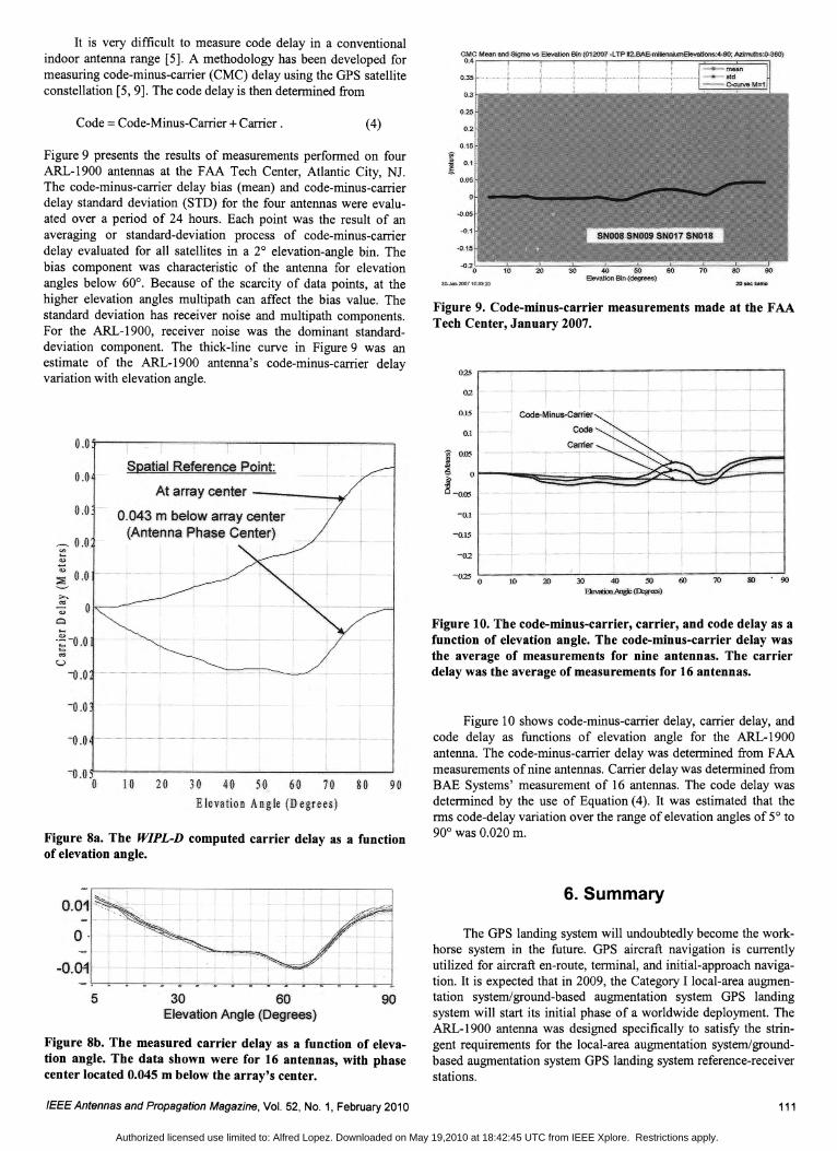
Figure 6c. The measured gain pattern (dBiRHCP).
Figure 6b. The computed gain pattern (dBiRHCP).
_Q.=-i,~
~=111-9d9ic
Figure 7. The measured gain patterns (dBiRHCP) for the Lland L2 frequencies.
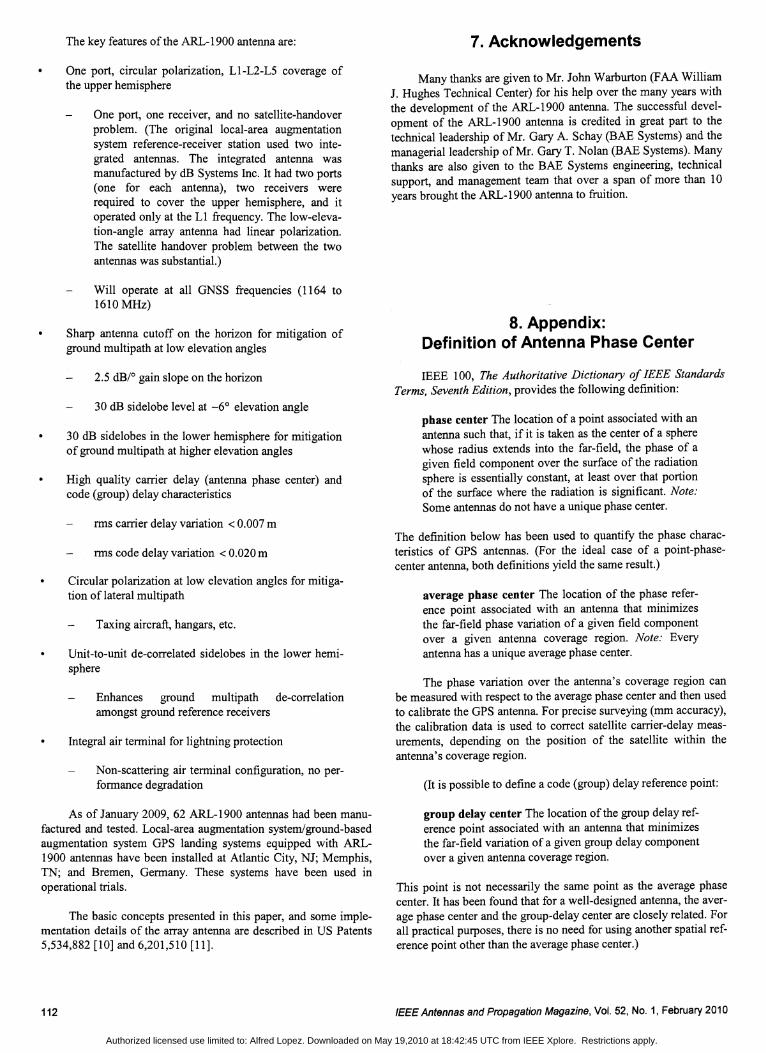
Figure 8b presents the measured carrier delay as a function ofelevation angle for 16 antennas (serial Nos. 003-018). The measurements were made at the BAE Systems indoor antenna range inGreenlawn, NY. The phase center (the phase-reference point thatminimizes the carrier-delay variation over the coverage region) waslocated 4.5 ern below the center element. The carrier-delay variation with elevation angle was ±O.OI0m. The consistency amongthe 16 antennas at any elevation angle was ±O.002 m.
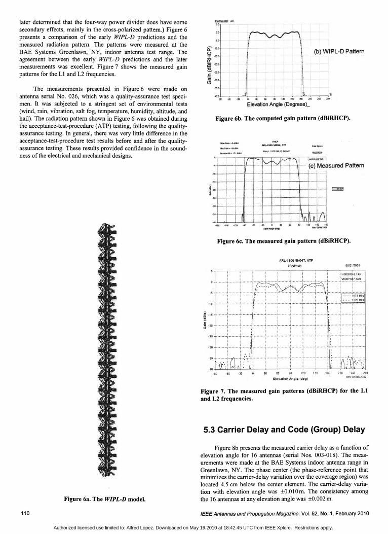
later determined that the four-way power divider does have somesecondary effects, mainly in the cross-polarized pattern.) Figure 6presents a comparison of the early WIPL-D predictions and themeasured radiation pattern. The patterns were measured at theBAE Systems Greenlawn, NY, indoor antenna test range. Theagreement between the early WIPL-D predictions and the latermeasurements was excellent. Figure 7 shows the measured gainpatterns for the L1 and L2 frequencies.
Figure 6a. The WIPL-D model.
The measurements presented in Figure 6 were made onantenna serial No. 026, which was a quality-assurance test specimen. It was subjected to a stringent set of environmental tests(wind, rain, vibration, salt fog, temperature, humidity, altitude, andhail). The radiation pattern shown in Figure 6 was obtained duringthe acceptance-test-procedure (ATP) testing, following the qualityassurance testing. In general, there was very little difference in theacceptance-test-procedure test results before and after the qualityassurance testing. These results provided confidence in the soundness of the electrical and mechanical designs.
110 IEEE Antennas and Propagation Magazine, Vol. 52, No.1, February 2010
Authorized licensed use limited to: Alfred Lopez. Downloaded on May 19,2010 at 18:42:45 UTC from IEEE Xplore. Restrictions apply.
It is very difficult to measure code delay in a conventionalindoor antenna range [5]. A methodology has been developed formeasuring code-minus-carrier (CMC) delay using the GPS satelliteconstellation [5, 9]. The code delay is then determined from
Figure 9 presents the results of measurements performed on fourARL-1900 antennas at the FAA Tech Center, Atlantic City, NJ.The code-minus-carrier delay bias (mean) and code-minus-carrierdelay standard deviation (STD) for the four antennas were evaluated over a period of 24 hours. Each point was the result of anaveraging or standard-deviation process of code-minus-carrierdelay evaluated for all satellites in a 2° elevation-angle bin. Thebias component was characteristic of the antenna for elevationangles below 60°. Because of the scarcity of data points, at thehigher elevation angles multipath can affect the bias value. Thestandard deviation has receiver noise and multipath components.For the ARL-1900, receiver noise was the dominant standarddeviation component. The thick-line curve in Figure 9 was anestimate of the ARL-1900 antenna's code-minus-carrier delayvariation with elevation angle.
II) . 907030 40 so 6)
BIMDD.Ang)e (D::w«s)
30 40 50Elevation Bin (degrees)
20
20
]0
10
-02
-0;25 0
Figure 9. Code-minus-carrier measurements made at the FAATech Center, January 2007.
-0.15
-0.1
0.15 Code-Minus-C8rrier
02
CO~-~_"',_~(!l1~"LT"I2.~--fj - , ............... mean
O.35~'l~.... ... ,., .. ,.'.I .....,~~,,,,..,.,~, c.eurve·'M=1
OJ
025 r----------------------,
Figure 10. The code-minus-carrier, carrier, and code delay as afunction of elevation angle. The code-minus-carrier delay wasthe average of measurements for nine antennas. The carrierdelay was the average of measurements for 16 antennas.
(4)
Spatial Reference Point
At array center - ...:......~
O.043m below array center(Antenna Phase Center)
Code =Code-Minus-Carrier +Carrier.
0.0
0.0
o
___ 0.0t'-).....u~
i 0.0
J-oI
·~-o.o«S
U
-0.0
Figure 8a. The WIPL-D computed carrier delay as a functionof elevation angle.
-0.0
-0.0
10 20 3t 40 50 60 10 80Elevation Angle (Degrees)
Figure 10 shows code-minus-carrier delay, carrier delay, andcode delay as functions of elevation angle for the ARL-1900antenna. The code-minus-carrier delay was determined from FAAmeasurements of nine antennas. Carrier delay was determined fromBAE Systems' measurement of 16 antennas. The code delay wasdetermined by the use of Equation (4). It was estimated that therms code-delay variation over the range of elevation angles of 50 to900 was 0.020 m.
Figure 8b. The measured carrier delay as a function of elevation angle. The data shown were for 16 antennas, with phasecenter located 0.045 m below the array's center.
6. Summary
The GPS landing system will undoubtedly become the workhorse system in the future. GPS aircraft navigation is currentlyutilized for aircraft en-route, terminal, and initial-approach navigation. It is expected that in 2009, the Category I local-area augmentation system/ground-based augmentation system GPS landingsystem will start its initial phase of a worldwide deployment. TheARL-1900 antenna was designed specifically to satisfy the stringent requirements for the local-area augmentation system/groundbased augmentation system GPS landing system reference-receiverstations.
9030 60Elevation Angle (Degrees)
5
o·-0.011
!-- ..~~------;;;----;.--=--~-;--------;;;--:;---:--;----;;----::;;---:-----;--------;;----;;~
IEEE Antennas and Propagation Magazine, Vol. 52, No.1, February 2010 111
Authorized licensed use limited to: Alfred Lopez. Downloaded on May 19,2010 at 18:42:45 UTC from IEEE Xplore. Restrictions apply.
The key features of the ARL-1900 antenna are:
One port, circular polarization, LI-L2-L5 coverage ofthe upper hemisphere
One port, one receiver, and no satellite-handoverproblem. (The original local-area augmentationsystem reference-receiver station used two integrated antennas. The integrated antenna wasmanufactured by dB Systems Inc. It had two ports(one for each antenna), two receivers wererequired to cover the upper hemisphere, and itoperated only at the Ll frequency. The low-elevation-angle array antenna had linear polarization.The satellite handover problem between the twoantennas was substantial.)
Will operate at all GNSS frequencies (1164 to1610 MHz)
Sharp antenna cutoff on the horizon for mitigation ofground multipath at low elevation angles
2.5 dB/o gain slope on the horizon
30 dB sidelobe level at -6° elevation angle
30 dB sidelobes in the lower hemisphere for mitigationof ground multipath at higher elevation angles
High quality carrier delay (antenna phase center) andcode (group) delay characteristics
rms carrier delay variation < 0.007 m
rms code delay variation < 0.020 m
Circular polarization at low elevation angles for mitigation of lateral multipath
Taxing aircraft, hangars, etc.
Unit-to-unit de-correlated sidelobes in the lower hemisphere
Enhances ground multipath de-correlationamongst ground reference receivers
Integral air terminal for lightning protection
Non-scattering air terminal configuration, no performance degradation
As of January 2009, 62 ARL-1900 antennas had been manufactured and tested. Local-area augmentation system/ground-basedaugmentation system GPS landing systems equipped with ARL1900 antennas have been installed at Atlantic City, NJ; Memphis,TN; and Bremen, Germany. These systems have been used inoperational trials.
The basic concepts presented in this paper, and some implementation details of the array antenna are described in US Patents5,534,882 [10] and 6,201,510 [11].
112
7. Acknowledgements
Many thanks are given to Mr. John Warburton (FAA William1. Hughes Technical Center) for his help over the many years withthe development of the ARL-1900 antenna. The successful development of the ARL-1900 antenna is credited in great part to thetechnical leadership of Mr. Gary A. Schay (BAE Systems) and themanagerial leadership of Mr. Gary T. Nolan (BAE Systems). Manythanks are also given to the BAE Systems engineering, technicalsupport, and management team that over a span of more than 10years brought the ARL-1900 antenna to fruition.
8. Appendix:Definition of Antenna Phase Center
IEEE 100, The Authoritative Dictionary of IEEE StandardsTerms, Seventh Edition, provides the following definition:
phase center The location of a point associated with anantenna such that, if it is taken as the center of a spherewhose radius extends into the far-field, the phase of agiven field component over the surface of the radiationsphere is essentially constant, at least over that portionof the surface where the radiation is significant. Note.'Some antennas do not have a unique phase center.
The definition below has been used to quantify the phase characteristics of GPS antennas. (For the ideal case of a point-phasecenter antenna, both definitions yield the same result.)
average phase center The location of the phase reference point associated with an antenna that minimizesthe far-field phase variation of a given field componentover a given antenna coverage region. Note: Everyantenna has a unique average phase center.
The phase variation over the antenna's coverage region canbe measured with respect to the average phase center and then usedto calibrate the GPS antenna. For precise surveying (mm accuracy),the calibration data is used to correct satellite carrier-delay measurements, depending on the position of the satellite within theantenna's coverage region.
(It is possible to define a code (group) delay reference point:
group delay center The location of the group delay reference point associated with an antenna that minimizesthe far-field variation of a given group delay componentover a given antenna coverage region.
This point is not necessarily the same point as the average phasecenter. It has been found that for a well-designed antenna, the average phase center and the group-delay center are closely related. Forall practical purposes, there is no need for using another spatial reference point other than the average phase center.)
IEEEAntennasand Propagation Magazine, Vol. 52, No.1, February 2010
Authorized licensed use limited to: Alfred Lopez. Downloaded on May 19,2010 at 18:42:45 UTC from IEEE Xplore. Restrictions apply.

9. References
1. M. Kayton, "Navigation Land, Sea, Air, & Space," New York,IEEE Press, 1990, p. 237.
2. FAA Web site, "Local Area Augmentation System - How ItWorks," available at http://www.faa.gov/about/office_org/headquarters_offices/ato/service_units/techops/navservices/gnss/laas/howitworks/ .
3. A. R. Lopez, "LAAS/GBAS Ground Reference Antenna withEnhanced Mitigation of Ground Multipath," Proceedings of theInstitute of Navigation National Technical Meeting, January 2008;http://www.arlassociates.net/2008GPSAntGrndReflect.pdf.
4. A. R. Lopez, "LAAS Reference Antennas - Circular Polarization Mitigates Multipath Effects," Proceedings of the Institute ofNavigation Annual Meeting, June 2003; http://www.arlassociates.net/2003GPSAntCPEffects.pdf.
5. A. R. Lopez, "Calibration of LAAS Reference Antennas," Proceeding of the 14th International Technical Meeting of the SatelliteDivision of the Institute of Navigation, September 2001; http://www.arlassociates.net/2001GPSAntCalibration.pdf.
6. FAA, "Lightning and Surge Protection, Grounding, Bonding andShielding Requirements for Facilities and Electronic Equipment,"FAA-STD-019d, August 9,2002.
7. A. R. Lopez, "Sharp Cutoff Radiation Patterns," IEEE Transactions on Antennas and Propagation, AP-27, 6, November 1979,pp. 820-824; http://www.arlassociates.net/Nov1979ArraySharpCutoff.pdf.
8. A. R. Lopez, "GPS Reference Antennas for Local AugmentationSystem, LAAS," Proceedings of the National Technical Meeting ofThe Institute of Navigation, January 2000; http://www.arlassociates.net/2000GPSAnt.pdf.
9. M. S. Braasch, "Multipath Effect," in B. W. Parkinson and J. J.Spilker (eds.), Global Positioning Theory and Application, Volume1, Reston, VA, AIAA, 1996, Chapter 14, pp. 560-566.
IEEEAntennasand Propagation Magazine, Vol. 52, No.1, February 2010
10. A. R. Lopez, GPS Antenna Systems, US Patent 5,534,882,issued July 9,1996.
11. A. R. Lopez, R. J. Kumpfbeck, and E. M. Newman, Self-Contained Progressive-Phase GPS Elements and Antennas, US Patent6,201,510, issued March 13,2001.
Introducing the Feature Article Author
Alfred R. Lopez is an IEEE Life Fellow and a BAE SystemsEngineering Fellow. He has 50 years of experience in antennadesign, propagation analysis, and the design and development ofradiating systems. All of this time he has been with BAE systems,through a heritage linking back to the Hazeltine Corporation andWheeler Laboratories, where he started his career in 1958. Overmost of his career, he has specialized in antenna designs and systems for aircraft-approach and landing operations. He has alsocontributed to the fields of electronically scanned array antennas,antennas for cellular communications, and ground reference antennas for differential GPS.
In 1958, he received the BEE from Manhattan College, and in1963, he received the MSEE from the Polytechnic Institute ofBrooklyn. He has published more than 60 papers in IEEE andInstitute of Navigation publications. He has been awarded 48 USpatents, and has received several awards from the IEEE and BAESystems. EID
113
Authorized licensed use limited to: Alfred Lopez. Downloaded on May 19,2010 at 18:42:45 UTC from IEEE Xplore. Restrictions apply.