GPR Survey of Rochester Cathedral Crypt & South Quire ... · GPR Survey of Rochester Cathedral...
20
Published online by Rochester Cathedral Research Guild Homepage: www.rochestercathedralresearchguild.org GPR Survey of Rochester Cathedral Crypt & South Quire Aisle GSB Prospection Abstract: To locate and characterise any anomalies of possible archaeological interest within the two areas of study. The work forms part of a wider archaeological evaluation being carried out on behalf of Rochester Cathedral. This work was enabled by a grant from the Heritage Lottery Fund. To cite this report: GSB Prospection (2011) GPR Survey of Rochester Cathedral Crypt & South Quire Aisle. GSB Prospection archive report 2011/64. To link to this article: https://rochestercathedralresearchguild.org/bibliography/2011-02 Published online: 26 th September 2017 General Queries: [email protected] Produced by permission of the Dean and Chapter of Rochester Cathedral. All rights reserved to the author. Digitisation has been funded by the Heritage Lottery Fund. Any views and opinions expressed in this work are those of the authors alone and do not necessarily reflect the official policy or position of either the Research Guild or the Dean and Chapter.
-
Upload
hoangkhanh -
Category
Documents
-
view
216 -
download
0
Transcript of GPR Survey of Rochester Cathedral Crypt & South Quire ... · GPR Survey of Rochester Cathedral...

Published online by
Rochester Cathedral
Research Guild
Homepage: www.rochestercathedralresearchguild.org
GPR Survey of Rochester Cathedral Crypt & South Quire Aisle GSB Prospection Abstract: To locate and characterise any anomalies of possible archaeological interest within the two areas of study. The work forms part of a wider archaeological evaluation being carried out on behalf of Rochester Cathedral. This work was enabled by a grant from the Heritage Lottery Fund. To cite this report: GSB Prospection (2011) GPR Survey of Rochester Cathedral Crypt & South Quire Aisle. GSB Prospection archive report 2011/64. To link to this article: https://rochestercathedralresearchguild.org/bibliography/2011-02 Published online: 26th September 2017 General Queries: [email protected] Produced by permission of the Dean and Chapter of Rochester Cathedral. All rights reserved to the author. Digitisation has been funded by the Heritage Lottery Fund. Any views and opinions expressed in this work are those of the authors alone and do not necessarily reflect the official policy or position of either the Research Guild or the Dean and Chapter.

Cowburn Farm, Market Street, Thornton, Bradford, West Yorkshire, BD13 3HW
Tel: +44 1274 835016Fax: +44 1274 830212
Email: [email protected]: www.gsbprospection.com
Specialising in Shallow and Archaeological Geophysics
GEOPHYSICAL SURVEY REPORT2011/64
Hidden Treasures Fresh ExpressionsGPR Survey of Rochester Cathedral
Crypt & South Quire Aisle
Client:

2011/64 – Rochester Cathedral Crypt & South Quire Aisle 1
GSB Survey No. 2011/64
GPR Survey of Rochester Cathedral Crypt& South Quire Aisle
NGR TQ 742 685Location Survey was conducted across the accessible areas of Rochester Cathedral's Crypt and in
the South Quire Aisle, at the top and bottom of the Kent Steps.County KentDistrict Medway (B)Parish n/aTopography FlatCurrent Land Use Cathedral ground floor and Crypt.Soils UrbanGeology Lewes nodular chalk formation [BGS 2011]Archaeology The western end of the Crypt dates back to the Cathedral's Norman origins, whilst the
remainder is of a later construction. The east end of the Norman Cathedral is believed to lie beneath the later Crypt, and as such is one of the key targets for the survey. Little is known about what might be beneath the South Quire Aisle but Medieval stratigraphy was recorded during 19th century excavations in the Quire [G.Keevil, pers. comm.].
Survey Methods Ground penetrating radar survey
Aims
To locate and characterise any anomalies of possible archaeological interest within the two areas of study. The work forms part of a wider archaeological evaluation being carried out on behalf of Rochester Cathedral. This work was enabled by a grant from the Heritage Lottery Fund.
Summary of Results *
The Crypt data have been badly affected in places by the flooring and services/drains crossing immediately beneath it. Potential footings have been recorded adjacent to some of the present walls and stone piers along with two anomalous zones of disturbance whose origins could well be archaeological; unfortunately, the limited 'window' of data unaffected by flooring and service runs has precluded definitive interpretation. Graves have been identified in both the Crypt and South Quire Aisle; some correlate with ledger stones whilst others do not and some of the ledger stones have little response associated with them, perhaps suggesting they have been repositioned.
In the South Quire Aisle, around the base of the Kent Steps, a linear band of response has been very tentatively interpreted as a potential earlier phase of construction on this southern side of the Cathedral. It has the appearance of foundation remnants, despite having a couple of graves dug in nearby. At the top of the stairs the subsurface looks relatively homogeneous down to around 0.8m where the top of the underlying Crypt room has been recorded.
Project Information
Project Co-ordinator Jimmy Adcock BSc MSc
Project Assistants J Gater & J TannerDate of Fieldwork 22nd - 24th November 2011Date of Report 16th December 2011
*It is essential that this summary is read in conjunction with the detailed results of the survey.
© GSB Prospection Ltd. For the use of Rochester Cathedral

2011/64 – Rochester Cathedral Crypt & South Quire Aisle 2
Survey Specifications
Method
All survey grid positioning was carried out by GSB Prospection using measuring tapes. The geophysical survey areas have been tied in to structural details and located, using these, on the architect's plans supplied by the client. These tie-ins are presented in Figures T1 & T2. Please refer to these diagrams when re-establishing the grid or positioning trenches.
Technique Instrument Traverse Interval Sample Interval Survey SizeGPR MALA
Ramac 500MHz 0.5m 0.05m ~550m2
1108m Traverse Data
Data Processing
Data processing was performed as appropriate using both in-house and commercial software packages (Geoplot, GPR Slice etc.) as outlined below.
GPR DataRubberbanding and manual gain (all data), background removal & migration (summary plots / where indicated).
Presentation of Results
Report Figures(Printed & Archive CD):
Site location, data plots and interpretation diagrams on base map (Figures 1-9).
Appendix 1 (Printed & Archive CD): Technical Information on instrumentation, survey methods, data processing, presentation and interpretation.
Reference Figures (Archive CD): Data plots at 1:500 / 1:200 for reference and analysis plus tie-in information (see List of Figures). Radargram images (jpeg format).
General Considerations
Conditions for survey were relatively good, being indoors and level. The South Quire Aisle was free of obstructions (other than the Kent Steps, which were not deemed suitable for survey) but the Crypt survey was less straightforward with multiple flooring types and obstacles including columns, an altar table and a small kitchen.
Any depths referred to in the interpretation of GPR data are only ever an approximation. The conversion from delay time to depth depends upon the propagation velocity of radar waves through the ground; this can vary significantly both laterally and vertically on some sites. An average velocity of 0.114m/ns has been used, after an iterative process of fitting hyperbolic curves to point-source reflections. Where there is a strong electromagnetic contrast, the GPR signal can be inter-reflected or reverberated, producing a delay in the reflection of the signal. This is termed ‘ringing’ and happens to some extent with all reflections, resulting in a greater apparent depth extent than actually exists. As a result, it is often not possible to detect the base of features; only the tops of buried deposits are detected with any kind of certainty [Annan 1996]. Particularly strong ringing is often seen when buried metallic debris is encountered and this material is generally assumed to be of modern origins.
All GPR interpretations are based on analysis of both raw and filtered depth-slice datasets as well as the original radargrams.
© GSB Prospection Ltd. For the use of Rochester Cathedral

2011/64 – Rochester Cathedral Crypt & South Quire Aisle 3
Results of Survey
1. Crypt
1.1 The success of the survey within the Cathedral's undercroft was limited by the effect of the flooring and services laid within and below it. In places the large concrete slabs seem to have acted as a barrier to the GPR signal. Strong responses (e.g. 1) have been recorded from the concrete itself but very little has been returned from beneath that is not simply 'ringing' (also seen as repeating parallel bands of increased response through the radargrams). That said, the effect is not across the entirety of the concrete flooring, perhaps suggesting that certain sections have a differing construction. Compounding the issue are spurious reflections from the roof of the Crypt, which become apparent from the equivalent of around 1.4m depth. Linear bands of response (2) are coincident with two strips of tiling, the northernmost between two concrete slabs and the southern example at the edge of the wooden flooring, across the southern extreme of the Crypt. Other shallow responses thought to be associated with changes in the flooring or its bedding material, rather than archaeological features, have been recorded in the extreme south-east of the survey area and within the Norman part of the Crypt.
1.2 A number of drains and service routes have been detected, some are very clear, for example the electric conduit (3) and a drain [Keevil, pers. comm.] crossing through the small chapel (4). Another very strong band of reflectors (5) run across the western end of the Norman part of the Crypt and are assumed to be relatively modern. The line of others are less clear and could be the result of changes between flooring units but comparison with the Cathedral plans should help confirm the origins of these responses, one way or the other.
1.3 In terms of definite archaeological deposits, the only features identified are an historic drain (under a small cover in the north-east of the Crypt) and a number of burials. There is some question over the extent of burials within the Crypt and the position of Ledger stones; those responses marked (G) have a character typical of in-situ burials beneath slabs whilst the remaining, less extensive, anomalies could be just the effect of the ledger stones having been relaid from elsewhere. No others interments have been detected, although it is possible that some may have been masked by the later works (e.g. flooring). The aforementioned drain does not appear to have anything running into or away from it, and although there is a linear trend running nearby to the south, the flooring here has again been problematic.
1.4 Increased reflectivity has been recorded immediately adjacent to some walls (6) and is possibly foundation material; perhaps in these areas the footings are slightly wider. Anomalous but shallow areas of disturbance (7) were recorded within the Norman section of the Crypt but their distribution and character do little to suggest that archaeology should be considered over and above effects from the flooring or natural variation within the immediately underlying strata. That said, excavations during the 1990s revealed archaelogical deposits along the west wall [G.Keevil, pers. comm.] A somewhat stronger reflector (8) between two stone piers may be archaeological and evidence of a continuous foundation underlying these piers; no such response was recorded between the equivalent piers on the southern side of the Crypt.
1.5 A broad area of disturbance (9) has a lack of form to its distribution which makes assigning an interpretation difficult and it is entirely possible that it is simply a facet of the underlying natural deposits. However, given the context, it is possible that this is evidence of residual foundation material from the original Norman east end; whether it was apsidal or squared, remains unclear. Had the flooring been less problematic, it may have been possible to get a better 'feel' for the context of these features, see how far they extend (if what is seen here is not the true limits) and determine, more definitively, their most likely origin. Similarly, a short band of disturbance (10) could be part of an, admittedly narrow looking, linear west-east structure but the flooring masks the rest of its projected line. Any interpretation is also heavily tempered by the presence of what may be a service, in the shallower slices, running from the electricity distribution board in the north-west corner of the room to the adjacent pillar.
© GSB Prospection Ltd. For the use of Rochester Cathedral

2011/64 – Rochester Cathedral Crypt & South Quire Aisle 4
2. South Quire Aisle
Bottom of the Kent Steps2.1 There are really only three types of response recorded in the South Quire Aisle. First are the clear
reflectors associated with burials, the effects of which 'ring' down through the data. The clearest examples have, again, been marked (G) with the third example being less well-defined.
2.2 Second, a set of responses (11) manifest themselves as a band of disturbed ground, or rubble-like material, running through the centre of the survey area, in parallel to the main axis of the Cathedral. This is thought to be the later 11th Century footings along the south side of the cathedral which became redundant when the South Quire Aisle was widened in the 12 th/13th Century [G.Keevil, pers. comm.]. There is a branch (12) to the south, running towards the bottom of the Kent Steps and a door into the Cloister garden. Given the breadth and depth of this feature it seems unlikely that it represents some form of service route which has been dug out and back-filled. Current thinking is that this may be evidence of Gundulf's Lesser Tower, believed to have been located in this vicinity [G.Keevil, pers. comm.].
2.3 Although weaker in the depth-slices than the previous anomalies, the rectilinear 'bulge' (13) on the northern side of (11) does seem to be formed of a relatively discrete zone of reflectors in the radargrams and, as such, is likely to be real. It seems possible that this relates to an earlier phase of construction at the Cathedral, along this southern side of the building. A much weaker zone of response exists to the north at the top of the stairs down to the Crypt, but how significant this is remains unclear.
Top of the Kent Steps2.4 In this area, only a small number of radargrams were collected (see Figure 9). The results are perhaps, as
to be expected – there appears to be a relatively homogeneous stratigraphy down to approximately 0.8m where a strong reflector is thought to represent the top of the Crypt ceiling. According to architects plans, the difference in height between the underside of the Crypt roof and the floor level at the top of the Kent Steps is 0.93m; the disparity is presumably the thickness of the ceiling material. Below this 'horizon' the responses are simply a facet of the radar energy being inter-reflected.
3. Conclusions
3.1 In the South Quire Aisle, around the base of the Kent Steps, a linear bands of response have been tentatively interpreted as a potential earlier phase of construction, possibly representing the former south wall of the Cathedral and perhaps even part of Gundulf's Lesser Tower, the exact position of which has, until now, remained unclear. Caution should be exercised however, as the presence of two nearby graves may be confusing the true layout. At the top of the stairs the subsurface looks relatively homogeneous down to around 0.8m where the top of Crypt has been recorded.
3.2 The Crypt data have been affected in places by the flooring and services/drains crossing immediately beneath it. Potential footings have been recorded adjacent to some of the present walls and stone piers along with two anomalous zones of disturbance whose origins could well be archaeological. The limited 'window' of data unaffected by flooring and service runs has precluded definitive interpretation of these reflections but the hope is that they are part of the original Norman east end. Defining whether this was likely to have been apsidal or squared-off has not been possible. A number of clear graves correlate with some of the stone ledgers in the floor but little evidence of any features associated with an extant drain have been recorded.
© GSB Prospection Ltd. For the use of Rochester Cathedral

2011/64 – Rochester Cathedral Crypt & South Quire Aisle 5
References
Annan, P 1996 GPR Workshop Notes. Sensors & Software, Mississauga, Canada
BGS 2011 British Geological Survey Geology Viewer.maps.bgs.ac.uk/geologyviewer/ [Accessed 9/12/2011]
List of Figures
Report Figures (Printed and on CD)
Figure 1 Site Location Diagram 1:50000
Figure 2 Location of Survey Areas 1:500
Figure 3 Crypt – Summary Depth-slices 1:500Figure 4 Crypt – Summary Interpretation 1:500
Figure 5 South Quire Aisle – Summary Depth-slices 1:200Figure 6 South Quire Aisle – Summary Interpretation 1:200
Figure 7 Crypt – Filtered 0.4m Depth-slices 1:500
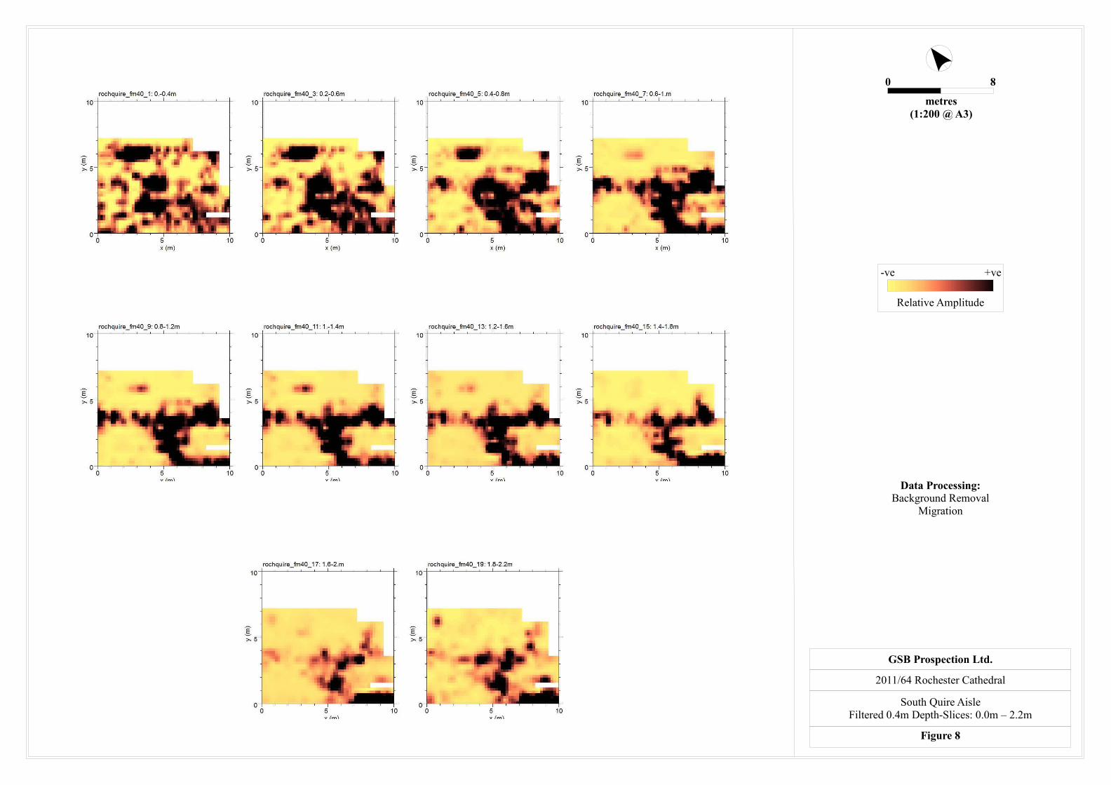
Figure 8 South Quire Aisle – Filtered 0.4m Depth-slices 1:200
Figure 9 South Quire Aisle – Radargrams From Top of Kent Steps not to scale
Reference Figures (CD only)
Figure A1 Crypt - Raw 0.1m Depth-Slices: 0.0m – 1.2m 1:500Figure A2 Crypt – Raw 0.1m Depth-slices: 1.2m – 2.0m 1:500Figure A3 Crypt – Raw 0.4m Depth-slices: 0.0m – 2.2m 1:500
Figure A4 Crypt – Filtered 0.1m Depth-slices: 0.0m – 1.2m 1:500Figure A5 Crypt – Filtered 0.1m Depth-slices: 1.2m – 2.0m 1:500
Figure A6 South Quire Aisle – Raw 0.1m Depth-slices: 0.0m – 2.0m 1:200Figure A7 South Quire Aisle – Raw 0.4m Depth-slices: 0.0m – 2.2m 1:200
Figure A8 South Quire Aisle – Filtered 0.1m Depth-slices: 0.0m – 2.0m 1:200
Figure T1 Crypt – Tie-in Diagram 1:200Figure T2 South Quire Aisle – Tie-in Diagram 1:200
© GSB Prospection Ltd. For the use of Rochester Cathedral

Figure 1
Site Location Diagram
2011/64 Rochester Cathedral
Reproduced from the Ordnance Survey Map with the permissionof the Controller of HMSO © Crown Copyright (AL100018665)
GSB PROSPECTION Ltd.
0 2000metres
1:50000 @ A4
Location of site

Locations of GPRSurvey
GSB PROSPECTION Ltd.
Based on a survey drawing by The Downland Partnershipprovided by the client and reproduced with permission
2011/64 Rochester Cathedral
Location of Survey Areas
Figure 2
0 20metres
1:500 @ A3
SOUTH QUIRE AISLE
CRYPT

Based on a survey drawing by The Downland Partnershipprovided by the client and reproduced with permission
Figure 3
Summary Depth - slices
2011/64 Rochester Cathedral
GSB PROSPECTION Ltd.
0 20metres
1:500 @ A3
0.00m - 0.40m 0.40m - 0.80m
1.20m - 1.60m0.80m - 1.20m
High
Low
Amplitude

?ArchaeologyHigh amplitutde/increased response
Grave
FlooringHigh amplitude/increased response
Based on a survey drawing by The Downland Partnershipprovided by the client and reproduced with permission
Figure 4
Crypt - Summary Interpretation
2011/64 Rochester Cathedral
GSB PROSPECTION Ltd.
0 20metres
1:500 @ A3
0.00m - 0.40m 0.40m - 0.80m
1.20m - 1.60m0.80m - 1.20m
Uncertain originHigh amplitude/increased response
Services/?Services
Historic drain

Based on a survey provided by the clientand reproduced with permission
Figure 5
South Quire Aisle - Summary Depth - slices
2011/64 Rochester Cathedral
GSB PROSPECTION Ltd.
0 8metres
1:200 @ A3
0.00m - 0.40m 0.40m - 0.80m
1.20m - 1.60m0.80m - 1.20m
High
Low
Amplitude Individual traverses(Figure 9)

GraveHigh amplitude/increased response
?ArchaeologyHigh amplitude/increased response
Uncertain originIncreased response
FlooringIncreased response
Based on a survey drawing by The Downland Partnershipprovided by the clientand reproduced with permission
Figure 6
South Quire Aisle - Summary Interpretation
2011/64 Rochester Cathedral
GSB PROSPECTION Ltd.
0 8metres
1:200 @ A3
0.00m - 0.40m 0.40m - 0.80m
1.20m - 1.60m0.80m - 1.20m
Individual traverse(Figure 9)

GSB Prospection Ltd.2011/64 Rochester Cathedral
Crypt - Filtered 0.4m Depth-Slices: 0.0m – 2.2mFigure 7
0 20
metres(1:500 @ A3)
Relative Amplitude
-ve +ve Data Processing:Background Removal
Migration
0 8
metres(1:200 @ A3)
GSB Prospection Ltd.
2011/64 Rochester Cathedral
South Quire AisleFiltered 0.4m Depth-Slices: 0.0m – 2.2m
Figure 8
Relative Amplitude
-ve +ve
Data Processing:Background Removal
Migration

Traverse 003
Traverse 004 Traverse 005
Traverse 001 Traverse 002
GSB Prospection Ltd.2011/64 Rochester Cathedral
Radargrams From Top of Kent Steps Figure 9
Relative Amplitude
-ve +ve Not to Scale–
Raw Data
Crypt Roof Crypt Roof
Crypt Roof
Crypt RoofCrypt RoofMaterial Beneath Doorway Material Beneath Doorway
WEST EAST WEST EAST
SOUTH NORTH
SOUTH NORTH SOUTH NORTH

Appendix 1: Technical Information
Instrumentation
Fluxgate Gradiometer: Geoscan FM36/256 and Bartington Grad601-2Both the Geoscan and Bartington instruments comprise two fluxgate sensors mounted vertically apart; the distance between the sensors on the former is 500mm, on the latter 1000mm. The gradiometers are carried by hand, with the bottom sensor approximately 100-300mm from the ground surface. At each survey station, the difference in the magnetic field between the two fluxgates is measured in nanoTesla (nT). The sensitivity of the instrument can be adjusted; for most archaeological surveys the most sensitive range (0.1nT) is used. The fluxgate gradiometer suppresses any diurnal or regional effects. Generally, features up to 1m deep may be detected by this method. Having two gradiometer units mounted laterally with a separation of 1000mm, the Bartington instrument can collect two lines of data per traverse.Resistance Meter: Geoscan RM15This instrument measures the electrical resistance of the earth, using a system of four electrodes (two current and two potential.) Depending on the arrangement of these electrodes an exact measurement of a specific volume of earth may be acquired. This resistance value may then be used to calculate the earth resistivity. The most common arrangement is the Twin Probe configuration which involves two pairs of electrodes (one current and one potential): one pair remain in a fixed position, whilst the other measures the resistance variations across a grid. The resistance is measured in ohms and, when calculated, resistivity is in ohm-metres. The resistance method as used for standard area survey employs a probe separation of 0.5m, which samples to a depth of approximately 0.75m. The nature of the overburden and underlying geology will cause variations in this depth.GPR: Sensors & Software Noggin Smartcartplus The Noggin system includes an onboard digital video logger (DVL III), 250 MHz or 500MHz antenna, an odometer wheel and battery. It is, therefore, a fully integrated system. The built-in software uses the integrated odometer to provide an accurate distance measurement to the response. The data are recorded in digital format and can be processed to produce depth slice maps, 2D sections or 3D cubes.
Display Options
XY Trace This involves a line representation of the data. Each successive row of data is equally incremented in the Y axis, to produce a stacked profile effect. This display may incorporate a hidden-line removal algorithm, which blocks out lines behind the major peaks and can aid interpretation. The advantages of this type of display are that it allows the full range of the data to be viewed and shows the shape of the individual anomalies. The display may also be changed by altering the horizontal viewing angle and the angle above the plane. The output may be either colour or black and white. Greyscale This format divides a given range of readings into a set number of classes. Each class is represented by a specific shade of grey, the intensity increasing with value. All values above the given range are allocated the same shade (maximum intensity); similarly all values below the given range are represented by the minimum intensity shade. Similar plots can be produced in colour, either using a wide range of colours or by selecting two or three colours to represent positive and negative values. The assigned range (plotting levels) can be adjusted to emphasise different anomalies in the data-set.Relief Plot This is a method of display that creates a three dimensional effect by directing an imaginary light source on a given data set. Particular elements of the results are highlighted depending on the angle of strike of the light source. This display method is particularly useful when applied to resistance data to highlight subtle changes in resistance that might otherwise be obscured.3D Surface Plot This is similar to the XY trace, but in 3 dimensions. Each data point of a survey is represented in its relative position on the x and y axes and the data value is represented in the z axis. This gives a digital terrain, or topographic effect.RadargramRadar data comprise a record of reflection intensity against the time taken for the emitted energy to travel from the transmitter down to the reflector and back to the receiver. The resultant plot is effectively a vertical section through the ground along the line of the traverse, with time (depth) on the vertical axis, displacement on the horizontal axis and reflection intensity as a grey or colour scale.Time SliceIf a number of radargrams are collected over a grid, or in conjunction with GPS data, it is possible to reconstruct the entire dataset into a 3D volume. This can then be resampled to compile ‘plan’ maps of response strength at increasing time offsets (typically converted to show approximate depth), thus simplifying the visualisation of how anomalies vary beneath the surface across a survey area.Volume PlotRather than looking at discrete slices of data from the 3D volume, it is possible to strip away all reflections with intensity below a user-defined threshold, leaving just the strongest anomalies. This serves to create a rendered 3D model of the most substantial subsurface deposits which can then be rotated or enlarged/reduced to either animate the display or view it from any perspective.
© GSB Prospection Ltd

Data Processing
Zero Mean TraverseThis process which sets the background mean of each traverse within each grid to zero. The operation removes striping effects and edge discontinuities over the whole of the data set. It is usually only applied to gradiometer data.
Step CorrectionWhen gradiometer data are collected in 'zig-zag' fashion, stepping errors can sometimes arise. These occur because of a slight difference in the speed of walking on the forward and reverse traverses. The result is a staggered effect in the data, which is particularly noticeable on linear anomalies. This process corrects these errors
Interpolation
When geophysical data are presented as a greyscale, each data point is represented as a small square. The resulting plot can sometimes have a 'blocky' appearance. The interpolation process calculates and inserts additional values between existing data points. The process can be carried out with points along a traverse (the x axis) and/or between traverses (the y axis) and results in a smoother greyscale image.
DespikeIn resistance survey, spurious readings can occasionally occur, usually due to a poor contact of the probes with the surface. This process removes the spurious readings, replacing them with values calculated by taking the mean and standard deviation of surrounding data points. It is not usually applied to gradiometer data.
High Pass FilterCarried out over the whole a resistance data-set, the filter removes low frequency, large scale spatial detail, such as that produced by broad geological changes. The result is to enhance the visibility of the smaller scale archaeological anomalies that are otherwise hidden within the broad ‘background’ change in resistance. It is not usually applied to gradiometer data.
GPR Filters
There are a wide range of GPR filters available and their application will vary from project to project. The most commonly used are: Dewow (removes low frequency, down-trace instrument noise); DC-Shift (re-establishes oscillation of the radar pulse around the zero point); Bandpass Filtering (suppresses frequencies outside of the antenna’s peak bandwidth thus reducing noise); Background Removal (can remove ringing, instrument noise and minimize the near-surface ‘coupling’ effect); Migration (collapses hyperbolic tails back towards the reflection source).
Tie-in Techniques and Information
TapesA number of points on each survey grid are recorded by triangulating to at least two fixed points on the base map. If there is a lack of ‘hard detail’ in the mapping, some form of survey marker will be left in-situ for reference.NOTE: When re-establishing the grid (for excavation or other post-survey work) only data from the supplied tie-in diagram should be
used and NOT the report figures.Electronic Distance Measurers (EDM) / Total Stations (TST)This type of instrument measures the distance and angle to features with reference to a fixed point. Where possible the EDM will be set up over a point that can be re-established with relative ease, e.g. over map detail, a survey marker or at a point measureable by tapes. Distances and angles to permanent points of reference and/or map detail are recorded as well as at least two points per survey grid.NOTE: When re-establishing the grid (for excavation or other post-survey work) only data from the supplied tie-in diagram should be used and NOT the report figures.Global Positioning Systems (GPS)Using a roving receiver unit, these systems record the longitude, latitude and altitude of a given point by triangulating between a network of satellites. For survey-grade measurements, the accuracy is refined by integrating data from a fixed base station or local reference network. In addition to grid points, elements of map detail are collected to assess the existing base-map accuracy and, in worst-case scenarios, use the data on a non-georeferenced map. If the supplied mapping is found to be inaccurate, it is sometimes necessary to shift the position of GPS points (keeping their relative positions fixed) within the site plan to correlate cartographic features with the ‘real-world’ co-ordinates; this should be considered when using GPS to re-establish an existing survey grid (see note below). It should be noted that the accuracy of any GPS-positioned point is dependent upon both the system and the satellite geometry at the time of survey. On projects where multiple contractors have used GPS, the possibility of compound errors between original survey grid creation, tie-in information and grid re-establishment should be borne in mind when positioning trenches over recorded anomalies.NOTE: If re-establishing the grid with a GPS (for excavation or other post-survey work), use only the co-ordinates recorded on the tie-
in diagram or, if supplied, the GPS data file included on the Archive CD; relative positions in the report diagrams may be correct but absolute co-ordinates can vary if discrepancies in the base mapping have been encountered.
Terms Commonly used in the Interpretation of Results
Magnetic
ArchaeologyThis term is used when the form, nature and pattern of the response are clearly or very probably archaeological These anomalies, whilst considered anthropogenic, could be of any age.
? ArchaeologyThe interpretation of such anomalies is often tentative, with the anomalies exhibiting either weak signal strength or forming incomplete archaeological patterns. They may be the result of variable soil depth, plough damage or even aliasing as a result of data collection orientation.
Areas of Increased Magnetic Response These responses show no visual indications on the ground surface and are considered to have some archaeological potential.
Industrial Strong magnetic anomalies that, due to their shape and form or the context in which they are found, suggest the presence of kilns, ovens, corn dryers, metal-working areas or hearths. It should be noted that in many instances modern ferrous material can produce similar magnetic anomalies.
NaturalThese responses form clear patterns in geographical zones where natural variations are known to produce significant magnetic distortions e.g. palaeochannels or magnetic gravels.
? Natural These are anomalies that are likely to be natural in origin i.e. geological or pedological.
Ridge and FurrowThese are regular and broad linear anomalies that are presumed to be the result of ancient cultivation. In some cases the response may be the result of modern activity.
Ploughing TrendThese are isolated or grouped linear responses. They are normally narrow and are presumed modern when aligned to current field boundaries or following present ploughing.
Uncertain Origin
Often, anomalies (both positive and negative) will be recorded which stand out from the background magnetic variation yet show little to suggest an exact origin. This may be because the characteristics and distribution of the responses straddle the categories of “?Archaeology” and “?Natural” or that they are simply of an unusual form.
Trend This is usually an ill-defined, weak, isolated or obscured linear anomaly of unknown cause or date.
Areas of Magnetic Disturbance These responses are commonly found in places where modern ferrous or fired materials are present e.g. brick rubble. They are presumed to be modern.
Ferrous Response
This type of response is associated with ferrous material and may result from small items in the topsoil, larger buried objects such as pipes, or above ground features such as fence lines or pylons. Ferrous responses are usually regarded as modern. Individual burnt stones, fired bricks or igneous rocks can produce responses similar to ferrous material.
Resistance
Archaeology High or low res responses are clearly or very probably archaeological These anomalies, whilst considered anthropogenic, could be of any age.
? ArchaeologyThe interpretation of such anomalies is often tentative, with the anomalies exhibiting either weak signal strength or forming incomplete archaeological patterns. They may be the result of variable soil depth, plough damage or even aliasing as a result of data collection orientation.
NaturalThese responses form clear patterns in geographical zones where natural variations are known to produce significant magnetic distortions e.g. palaeochannels or magnetic gravels.
? Natural These are anomalies that are likely to be natural in origin i.e. geological or pedological.
? Landscaping / topographyThese are regular and broad linear anomalies that are presumed to be the result of ancient cultivation. In some cases the response may be the result of modern activity.
VegetationThese are isolated or grouped linear responses. They are normally narrow and are presumed modern when aligned to current field boundaries or following present ploughing.
Trend This is usually an ill-defined, weak, isolated or obscured linear anomaly of unknown cause or date.
© GSB Prospection Ltd
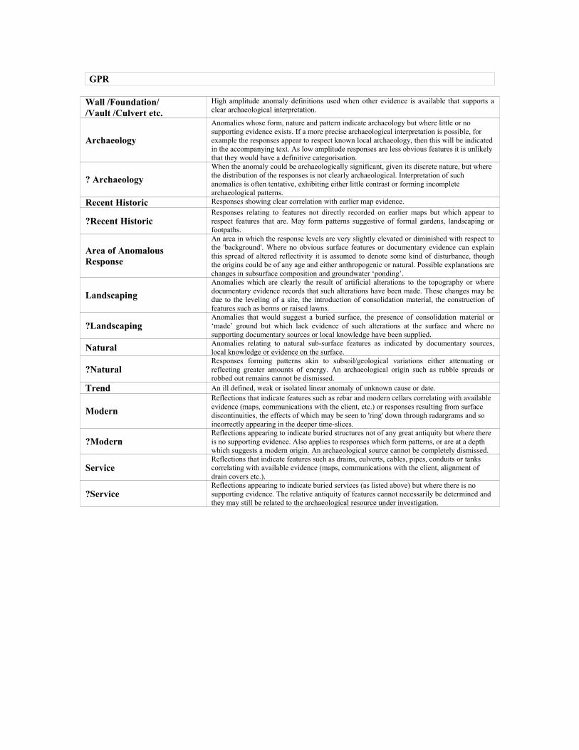
GPR
Wall /Foundation//Vault /Culvert etc.
High amplitude anomaly definitions used when other evidence is available that supports a clear archaeological interpretation.
Archaeology
Anomalies whose form, nature and pattern indicate archaeology but where little or no supporting evidence exists. If a more precise archaeological interpretation is possible, for example the responses appear to respect known local archaeology, then this will be indicated in the accompanying text. As low amplitude responses are less obvious features it is unlikely that they would have a definitive categorisation.
? ArchaeologyWhen the anomaly could be archaeologically significant, given its discrete nature, but where the distribution of the responses is not clearly archaeological. Interpretation of such anomalies is often tentative, exhibiting either little contrast or forming incomplete archaeological patterns.
Recent Historic Responses showing clear correlation with earlier map evidence.
?Recent HistoricResponses relating to features not directly recorded on earlier maps but which appear to respect features that are. May form patterns suggestive of formal gardens, landscaping or footpaths.
Area of Anomalous Response
An area in which the response levels are very slightly elevated or diminished with respect to the 'background'. Where no obvious surface features or documentary evidence can explain this spread of altered reflectivity it is assumed to denote some kind of disturbance, though the origins could be of any age and either anthropogenic or natural. Possible explanations are changes in subsurface composition and groundwater ‘ponding’.
LandscapingAnomalies which are clearly the result of artificial alterations to the topography or where documentary evidence records that such alterations have been made. These changes may be due to the leveling of a site, the introduction of consolidation material, the construction of features such as berms or raised lawns.
?LandscapingAnomalies that would suggest a buried surface, the presence of consolidation material or ‘made’ ground but which lack evidence of such alterations at the surface and where no supporting documentary sources or local knowledge have been supplied.
Natural Anomalies relating to natural sub-surface features as indicated by documentary sources, local knowledge or evidence on the surface.
?NaturalResponses forming patterns akin to subsoil/geological variations either attenuating or reflecting greater amounts of energy. An archaeological origin such as rubble spreads or robbed out remains cannot be dismissed.
Trend An ill defined, weak or isolated linear anomaly of unknown cause or date.
ModernReflections that indicate features such as rebar and modern cellars correlating with available evidence (maps, communications with the client, etc.) or responses resulting from surface discontinuities, the effects of which may be seen to 'ring' down through radargrams and so incorrectly appearing in the deeper time-slices.
?ModernReflections appearing to indicate buried structures not of any great antiquity but where there is no supporting evidence. Also applies to responses which form patterns, or are at a depth which suggests a modern origin. An archaeological source cannot be completely dismissed.
ServiceReflections that indicate features such as drains, culverts, cables, pipes, conduits or tanks correlating with available evidence (maps, communications with the client, alignment of drain covers etc.).
?ServiceReflections appearing to indicate buried services (as listed above) but where there is no supporting evidence. The relative antiquity of features cannot necessarily be determined and they may still be related to the archaeological resource under investigation.
![Crypt of Cthulhu #38 (1987.Cryptic)[CosmicJukebox] of Cthulhu/Misc/Crypt of Cthulhu/Crypt of... · Eastertide1986/5 foundinLovecraft'scellargallery: Alockedportfolio,boundintanned](https://static.fdocuments.us/doc/165x107/5b975f8609d3f27e758c8cfe/crypt-of-cthulhu-38-1987crypticcosmicjukebox-of-cthulhumisccrypt-of-cthulhucrypt.jpg)