
GP-Pro: The Generative Programming Protocol Generator for ...
174
GP-Pro: The Generative Programming Protocol Generator for Routing in Mobile Ad Hoc Networks Pedro Eduardo Villanueva Peña Thesis submitted to the Faculty of Graduate and Postdoctoral Studies In partial fulfillment of the requirements For the Doctor of Philosophy degree in Electrical Engineering School of Information Technology and Engineering Ottawa-Carleton Institute for Electrical and Computer Engineering University of Ottawa © Pedro Eduardo Villanueva Peña, Ottawa, Canada, 2009
Transcript of GP-Pro: The Generative Programming Protocol Generator for ...
GP-Pro: The Generative Programming
Protocol Generator for Routing
in Mobile Ad Hoc Networks
Pedro Eduardo Villanueva Peña
Thesis submitted to the
Faculty of Graduate and Postdoctoral Studies
In partial fulfillment of the requirements
For the Doctor of Philosophy degree in Electrical Engineering
School of Information Technology and Engineering
Ottawa-Carleton Institute for Electrical and Computer Engineering
University of Ottawa
© Pedro Eduardo Villanueva Peña, Ottawa, Canada, 2009
ii
Abstract
Routing in mobile ad hoc networks (MANETs), where network topology is potentially highly
dynamic, is not a trivial task. Routing protocols have been profoundly researched but only
four of them have reached RFC status (AODV, OLSR, TBRPF and DSR). Simulation is the
tool of choice to test and analyze routing protocols in a controlled environment, however, its
credibility has decreased due to simulations being poorly performed and the inaccurate match
of performance results with the results obtained from real test-bed deployments. One of the
reasons for that is that simulation studies do not always correctly reflect the physical realities.
On the other hand, the constantly increasing network requirements in terms of bandwidth,
robustness, reliability and quality of service for a broad range of multiplatform scenarios
demand for fast development and implementation of routing protocols that satisfy specific
user requirements. However, current practices for protocol development and implementation
are costly and time-consuming, especially when existing knowledge is not properly reused.
Generative Programming is an attractive solution that makes use of reusable components and
is also powered with the knowledge to automatically assemble them. This thesis analyzes the
problem of developing ad hoc routing protocols, proposes an approach to automate the
development process, and discusses in detail the design and the steps to build the GP-Pro
protocol generator. GP-Pro is based on Generative Programming and automatically generates
ad hoc routing protocols according to user requirements, which are expressed by means of a
specification language. GP-Pro is designed with the explicit goal of generating a large
number of different protocols by different component combinations and it addresses the
generation of proactive, reactive and position-based routing protocols ready for deployment.
To demonstrate the capabilities of GP-Pro, we generated deployable implementations
of the reactive protocol DYMO, the proactive protocol OLSR and the position-based
protocol GREEDY. It took about 8 months to develop GP-Pro and to generate the first
protocol (DYMO), but just about a week to generate the third protocol (GREEDY). The
more components are available, the faster the implementation can be achieved. Therefore,
iii
generation time is considerably reduced. Through performance evaluation over real
networks, we show that the generated protocols perform very closely to their handcrafted
counterparts.
This research work provides the following contributions: 1) A domain specific
protocol architecture; 2) A component interconnection model; 3) A robust protocol
specification mechanism; 4) GP-Pro the software tool and; 5) Further insights in related
fields.

iv
Acknowledgements
The Ph.D. journey has been longer and tougher than I originally thought it would be,
however, I am glad that I took the challenge. It is certainly something that I could have not
achieved on my own. Therefore, I am thankful to everyone who helped me to accomplish it,
whether professionally, emotionally, or financially. First, I want to thank CONACYT, The
National Council of Science and Technology of Mexico (my beloved home country), who
sponsored me during most of my Ph.D. studies. Without its support I would not have even
considered pursuing a Ph.D. Next, I want to thank my supervisors Dr. Ivan Stojmenovic and
Dr. Thomas Kunz. Thanks Ivan for being a supervisor or co-supervisor for all three theses
that I have written: Bachelor, Masters and Ph.D. Your teachings and guidance introduced me
and took me through the ad hoc routing world that I enjoy so much. To Thomas, thanks for
all your advice, and for your many questions that made me work harder, but that also made
for a more valuable and rewarding research experience. The weekly meetings and
discussions were very challenging at the beginning, but became supportive at the end.
Outside of the academia I owe a lot to my family and to my friends. Thanks to my
mother and sister whom I can always reach in Mexico through a phone call, and who always
take the time during my visits home to make it a very pleasant vacation. Very special thanks
to my long time friend Larissa Guzman who is always there when things get tough,
regardless of the distance (gracias Galleta). Thanks to my two good French Canadian friends
Anne Montpetit and Marc Billard, who I have shared many special moments with and who
are always willing to help when I need them (merci beaucoup les gars). Thanks to my
officemates Paul Elliot and Amy Cameron who shared similar joys of the Ph.D. life, which
made for more enjoyable hours during the Ph.D. isolation. Finally, I want to thank all my
other friends that I have met in Canada who have enriched my life experience during these
past five years, especially all those that I have met through various sports.
Pedro Eduardo Villanueva Peña, January 2009.
v
Contents
ABSTRACT............................................................................................................................ II
ACKNOWLEDGEMENTS ................................................................................................. IV
LIST OF FIGURES ...........................................................................................................VIII
LIST OF TABLES ................................................................................................................ IX
LIST OF ACRONYMS ......................................................................................................... X
INTRODUCTION................................................................................................................... 1
1.1 MOTIVATION ................................................................................................................................................3 1.2 DOMAIN........................................................................................................................................................3 1.3 CHALLENGES ................................................................................................................................................4 1.4 THESIS CONTRIBUTIONS ...............................................................................................................................6 1.5 PUBLICATIONS ..............................................................................................................................................9 1.6 THESIS ORGANIZATION...............................................................................................................................10
BACKGROUND ................................................................................................................... 11
2.1 MOBILE AD HOC NETWORKS .....................................................................................................................12 2.2 ROUTING ....................................................................................................................................................13
2.2.1 Routing in MANETs ...........................................................................................................................13 2.2.2 MANET Routing Protocols ................................................................................................................14
2.2.2.1 Proactive Protocols...................................................................................................................................... 15 2.2.2.2 Reactive Protocols....................................................................................................................................... 16 2.2.2.3 Hybrid Protocols ......................................................................................................................................... 17 2.2.2.4 Position Based Protocols............................................................................................................................. 17
2.2.3 Path Computation Metrics .................................................................................................................18 2.2.4 QoS Routing.......................................................................................................................................19 2.2.5 Routing Summary...............................................................................................................................19
2.3 LITERATURE REVIEW..................................................................................................................................20 2.3.1 Function Libraries .............................................................................................................................21 2.3.2 Frameworks .......................................................................................................................................21 2.3.3 Component-Based Software Engineering ..........................................................................................23 2.3.4 Generative Programming ..................................................................................................................25 2.3.5 Automatic Code Generation...............................................................................................................27 2.3.6 Frameworks for Ad Hoc Routing Protocols.......................................................................................29
2.4 SUMMARY ..................................................................................................................................................30
DOMAIN ANALYSIS .......................................................................................................... 32
3.1 INTRODUCTION TO GENERATIVE PROGRAMMING .......................................................................................32 3.2 DOMAIN ARCHITECTURE ............................................................................................................................34 3.3 FEATURE MODELING ..................................................................................................................................38 3.4 SUBFAMILIES OF PROTOCOLS .....................................................................................................................39
3.4.1 Proactive Protocols............................................................................................................................40 3.4.2 Reactive Protocols .............................................................................................................................42 3.4.3 Position-Based Protocols...................................................................................................................43
GP-PRO: ARCHITECTURE AND IMPLEMENTATION ............................................. 45
vi
4.1 GP-PRO ARCHITECTURE.............................................................................................................................46 4.1.1 User Specification..............................................................................................................................47 4.1.2 Specification Validation.....................................................................................................................48 4.1.3 Graphic User Interface ......................................................................................................................48 4.1.4 Specification Generator .....................................................................................................................48 4.1.5 Buildability Checking.........................................................................................................................49 4.1.6 Completing Specification ...................................................................................................................49 4.1.7 Components Selection ........................................................................................................................49 4.1.8 Components Assembly........................................................................................................................50 4.1.9 Additional Outputs .............................................................................................................................50
4.2 GP-PRO IMPLEMENTATION .........................................................................................................................50 4.2.1 Components Implementation..............................................................................................................50 4.2.2 Architecture Implementation..............................................................................................................53
4.2.2.1 XML and XVCL ......................................................................................................................................... 54 4.2.2.2 OpenArchitectureWare and XVCL ............................................................................................................. 55 4.2.2.3 OpenArchitectureWare only........................................................................................................................ 57
4.2.3 Kernel Interaction..............................................................................................................................57 4.2.4 What GP-Pro Does Not Do................................................................................................................59
COMPONENT INTERCONNECTION MODEL............................................................. 60
5.1 BASIC COMPONENTS...................................................................................................................................62 5.2 COMPOSITE COMPONENTS ..........................................................................................................................64 5.3 ROUTING BETWEEN COMPONENTS .............................................................................................................68 5.4 LIMITATIONS ..............................................................................................................................................70
GP-PRO: THE SOFTWARE TOOL.................................................................................. 71
6.1 SPECIFICATION LANGUAGE ........................................................................................................................71 6.2 PROTOCOL COMPONENTS ...........................................................................................................................74
6.2.1 Component Operation........................................................................................................................78 6.2.2 Message Types ...................................................................................................................................80 6.2.3 Protocol Subfamilies ..........................................................................................................................81
6.3 PROTOCOL SPECIFICATION .........................................................................................................................82 6.4 AUTOMATIC COMPLETION OF SPECIFICATIONS...........................................................................................87 6.5 ERROR HANDLING ......................................................................................................................................88 6.6 GENERATION TIME .....................................................................................................................................89
EVALUATION ..................................................................................................................... 91
7.1 GENERATED PROTOCOLS ............................................................................................................................91 7.1.1 OLSR Protocol ...................................................................................................................................92 7.1.2 GREEDY Protocol .............................................................................................................................95 7.1.3 Generalized Message Format ..........................................................................................................100 7.1.4 Protocol Variants.............................................................................................................................101
7.2 COMPARING GP-PRO AGAINST EXISTING FRAMEWORKS..........................................................................102 7.3 COMPARING THE GENERATED PROTOCOLS...............................................................................................104
7.3.1 Test-bed............................................................................................................................................106 7.3.2 Proper Routing.................................................................................................................................106 7.3.3 Resource Consumption ....................................................................................................................110
7.3.3.1 Standalone Mode....................................................................................................................................... 110 7.3.3.2 Data Transmission Mode........................................................................................................................... 112
7.4 SUMMARY ................................................................................................................................................114
CONCLUSIONS AND FUTURE WORK........................................................................ 116
APPENDICES..................................................................................................................... 120
APPENDIX A...................................................................................................................... 121
vii
APPENDIX B ...................................................................................................................... 128
APPENDIX C...................................................................................................................... 130
C.1 MADINI – INFORMATION SUBCOMPONENTS ...........................................................................................130 C.2 DELIVERY MECHANISMS..........................................................................................................................133 C.3 CONI.......................................................................................................................................................135 C.4 ADDITIONAL COMPUTATIONS ..................................................................................................................137 C.5 OPERATING SYSTEM INTERFACE..............................................................................................................138 C.6 PATH DETERMINATION ............................................................................................................................139 C.7 ROUTING INFORMATION REPOSITORY......................................................................................................141 C.8 EVENT MANAGER ....................................................................................................................................144 C.9 LOCATION INFORMATION.........................................................................................................................145
APPENDIX D...................................................................................................................... 146
APPENDIX E ...................................................................................................................... 150
APPENDIX F ...................................................................................................................... 151
APPENDIX G...................................................................................................................... 154
BIBLIOGRAPHY............................................................................................................... 155
viii
List of Figures
FIGURE 1. EXAMPLE OF AN AD HOC NETWORK ......................................................................... 13
FIGURE 2. GP-PRO DOMAIN ARCHITECTURE ............................................................................ 35
FIGURE 3. FEATURE DIAGRAM ................................................................................................. 38
FIGURE 4. ARCHITECTURE FOR THE SUBFAMILY OF PROACTIVE PROTOCOLS............................ 40
FIGURE 5. OLSR PROTOCOL ARCHITECTURE ........................................................................... 41
FIGURE 6. ARCHITECTURE FOR THE SUBFAMILY OF REACTIVE PROTOCOLS .............................. 41
FIGURE 7. DSR PROTOCOL ARCHITECTURE .............................................................................. 42
FIGURE 8. ARCHITECTURE FOR THE SUBFAMILY OF POSITION-BASED PROTOCOLS ................... 43
FIGURE 9. GFG PROTOCOL ARCHITECTURE.............................................................................. 44
FIGURE 10. GP-PRO ARCHITECTURE ........................................................................................ 45
FIGURE 11. HIERARCHICAL ARRANGEMENT OF COMPONENTS.................................................. 61
FIGURE 12. BASIC COMPONENT................................................................................................ 63
FIGURE 13. COMPOSITE COMPONENT ....................................................................................... 63
FIGURE 14. EXAMPLE OF GENERIC COMPOSITE COMPONENT .................................................... 64
FIGURE 15. EXAMPLE OF GENERIC COMPOSITE COMPONENT .................................................... 65
FIGURE 16. LOGICAL INTERCONNECTION OF COMPONENTS ...................................................... 66
FIGURE 17. MODIFIED LOGICAL INTERCONNECTION ................................................................ 67
FIGURE 18. MESSAGE WITH SENDER ID IN THE HEADER........................................................... 68
FIGURE 19. MESSAGE WITH DESTINATION ID IN THE HEADER .................................................. 68
FIGURE 20. COMPONENTS HIERARCHY OF Z............................................................................. 69
FIGURE 21. SCREENSHOT OF THE XTEXT FRAMEWORK INSIDE ECLIPSE ................................... 74
FIGURE 22. SCREENSHOT OF THE DEFINITION OF A TEMPLATE USING XPAND LANGUAGE ........ 77
FIGURE 23. STATE MACHINE REPRESENTING PROTOCOL OPERATION........................................ 80
FIGURE 24. SCREENSHOT OF THE DYMO PROTOCOL SPECIFICATION USING THE NEW DSL..... 85
FIGURE 25. GP-PRO LOGO ..................................................................................................... 154
ix
List of Tables
TABLE 1. APPROACHES TO IMPLEMENT THE ARCHITECTURE OF GP-PRO ................................. 53
TABLE 2. SUBCOMPONENTS OF Z ............................................................................................. 65
TABLE 3. MESSAGE/DESTINATION FOR ALL THE MDC’S.......................................................... 66
TABLE 4. NEW MESSAGE/DESTINATION TABLE......................................................................... 67
TABLE 5. MESSAGE TYPES....................................................................................................... 80
TABLE 6. SPECIFICATION ERRORS AND WARNINGS................................................................... 88
TABLE 7. TLVS SPECIFICATION ............................................................................................. 100
TABLE 8. QUALITATIVE COMPARISON BETWEEN EXISTING FRAMEWORKS ............................. 102
TABLE 9. PERFORMANCE OF DYMOUM ............................................................................... 107
TABLE 10. PERFORMANCE OF DYMO IMPLEMENTED WITH GP-PRO.................................... 107
TABLE 11. PERFORMANCE OF OLSRD................................................................................... 108
TABLE 12. PERFORMANCE OF OLSR IMPLEMENTED WITH GP-PRO...................................... 108
TABLE 13. PERFORMANCE OF GREEDY IMPLEMENTED WITH GP-PRO................................ 109
TABLE 14. IMPLEMENTATION SIZES IN BYTES ........................................................................ 111
TABLE 15. CONSUMED PHYSICAL MEMORY IN KBYTES......................................................... 111
TABLE 16. CPU UTILIZATION FOR DYMO OVER ONE HOP PATHS .......................................... 112
TABLE 17. CPU UTILIZATION FOR DYMO OVER THREE HOP PATHS ...................................... 113
TABLE 18. CPU UTILIZATION FOR OLSR OVER ONE HOP PATHS ............................................ 113
TABLE 19. CPU UTILIZATION FOR OLSR OVER THREE HOP PATHS ........................................ 113
TABLE 20. CPU UTILIZATION FOR GREEDY OVER ONE AND THREE HOP PATHS ................... 114
TABLE 21. LIST OF GENERATED TEMPLATES .......................................................................... 129
TABLE 22. RELATIONSHIP BETWEEN COMPONENT TYPES, XPAND TEMPLATES AND DSL
ABSTRACT RULES ........................................................................................................... 152
x
List of Acronyms
ACE Adaptive Communication Environment
AODV Ad hoc On-Demand Distance Vector
API Application Programming Interface
ASL Ad hoc Support Library
CBR Component-Based Routing
CBSE Component-Based Software Engineering
CEDAR Core Extraction Distributed Ad hoc Routing
CONI Collector of Network Information On-Demand
CPU Central Processing Unit
DREAM Distance Routing Effect Algorithm for Mobility
DSDV Destination-Sequenced Distance Vector
DSL Domain Specification Language
DSR Dynamic Source Routing
DTD Document Type Definition
DYMO Dynamic MANET On-Demand
ETX Expected Transmission Count
FreeBSD Free Berkeley Software Distribution
FSM Finite State Machine
GFG Greedy-Face-Greedy
GG Gabriel Graph
GP Generative Programming
GP-Pro Generative Programming Protocol Generator
GPS Global Positioning System
xi
GUI Graphic User Interface
HNA Host and Network Association
HSLS Hazy Sighted Link State
HTML Hypertext Markup Language
IARP Intrazone Routing Protocol
IERP Interzone Routing Protocol
IETF Internet Engineering Task Force
IPC Inter-Process Communication
IPv4 Internet Protocol Version 4
ISO International Organization for Standardization
JAXP Java API for XML Processing
LAR Location-Aided Routing
LKM Loadable Kernel Module
MAC Media Access Control
MADINI Manager for Distribution of Network Information
MANET Mobile Ad hoc Network
MDD Model-Driven Development
MID Multiple Interface Declaration
MPEG Moving Picture Experts Group
MPR Multi-Point Relay
MPRS Multi-Point Relay Selector
NHDP Neighborhood Discovery Protocol
oAW OpenArchitectureWare
OLSR Optimized Link State Routing
OS Operating System
OverML Overlay Modeling Language
PIX Protocol Implementation Framework for Linux
xii
PRAN Physical Realization of Ad hoc Networks
QoS Quality of Service
RFC Request for Comments
RIR Routing Information Repository
RNG Relative Neighborhood Graph
RREP Route Reply
RTT Route Trip Time
SGML Standard Generalized Markup Language
SMF Simplified Multicast Forwarding
SOCKS Abbreviation for Sockets
TBR Ticket Based Routing
TBRPF Topology Broadcast Based on Reverse-Path Forwarding
TC Topology Control
TTL Time to Live
UDP User Datagram Protocol
Wi-Fi Wireless Fidelity
WXS World Wide Web Consortium XML Schema
XML Extensible Markup Language
XORP Extensible Open Router Platform
XSL Extensible Stylesheet Language
XSLT Extensible Stylesheet Language Transformation
XVCL XML-based Variant Configuration Language
ZRP Zone Routing Protocol
1
Chapter 1
Introduction
MANETs (Mobile ad hoc networks) are infrastructure-less networks where the nodes are
potentially mobile and communication is achieved wirelessly. Due to node mobility and link
quality variations, the topology of such networks is potentially highly dynamic, which
challenges the performance and design of routing protocols. Substantial research has been
conducted in the field of ad hoc routing protocols and many protocols have been proposed.
Four protocols have been assigned RFC status by the IETF (Internet Engineering Task
Force), they are: AODV [1], OLSR [2], TBRPF [3], and more recently DSR [4]. However,
research is still ongoing, now trying to take advantage of the learned experiences. DYMO
[5], one of the newest protocols proposed by the IETF, which is a successor of AODV [1],
and OLSR version 2 [6] are examples of this trend. In order to test and analyze routing
protocols in a controlled environment under a large range of scenarios, simulation is the tool
of choice. However, as discussed in [7], the credibility of simulation studies has decreased
due to simulations being poorly performed and due to a lack of reliable and homogeneous
scenarios that allow repeatability and fair comparison. Actually, even if the simulation work
is well done, the results might not match those of real test-bed deployments well, as shown in
[8, 9] and [10]. One of the reasons for that is that simulation studies do not always correctly
reflect the physical realities, leading to performance results that do not match what is
obtained in the real world. Therefore, simulation work is not sufficient, as ultimately routing
protocols are to be implemented and tested in real test-beds. Thus, real protocol
implementations are required, even though implementing a protocol is no easy task.
Several approaches have been taken to support and to speed up the development of
communication protocols, some examples are: X-kernel [11], ACE [12] and PIX [13]. All of
these approaches are frameworks that support the implementation of protocols for any layer
in the protocol stack. Therefore, the programmer makes use of the available tools to
2
implement the desired protocol, meaning that the programmer still has to do a considerable
amount of programming. PIX [13] tries to reduce the amount of additional programming by
making use of Generative Programming (GP) [14] in order to automate the protocol
generation process based on a protocol specification. However, only the main architecture of
the protocol is generated by PIX and it is left to the programmer to code complementary
functionalities and all of the packet processing. Some other approaches are specifically
oriented to the domain of ad hoc routing protocols (the domain of our interest) such as ASL
(Ad hoc Support Library) [15], which is a library that supports the implementation of
reactive protocols.
In order to advance the state of the art, this research proposes a protocol generator for
the specific domain of routing in ad hoc networks, which applies Generative Programming
for the first time to this domain. The generator is called GP-Pro, the Generative
Programming Protocol generator for ad hoc routing protocols. The objective of GP-Pro goes
farther than the previous approaches. GP-Pro is designed to generate ad hoc routing protocols
by assembling existing components, based on user specifications. Consequently, the
programmer’s job is reduced to selecting the components to build the protocol that she/he
wants, by means of a specification mechanism. The range of protocol variability that can be
generated with GP-Pro depends on the number of existing components and their granularity.
Additional components can be added to GP-Pro at any time as long as they comply with the
proposed protocol architecture. Therefore, GP-Pro reduces the generation time of routing
protocols by providing a common architecture that maximizes the reusability of existing
components.
This idea of implementing routing protocols out of components is a perfect match for
the current efforts of the MANET working group [16] in the routing area of the IETF, which
is trying to create several standard features that could be reused by any other routing
protocol. Some of these features are: 1) The Generalized Packet/Message format, which is a
multi-message packet format that is expected to be used by routing and other MANET
protocols; 2) The Neighborhood Discovery Protocol (NHDP) that describes one-hop and
symmetric two-hop neighborhood discovery and; 3) A Simplified Multicast Forwarding
3
(SMF) mechanism which actually reuses the NHDP. In fact, the DYMO [5] protocol, which
was chosen to be the first protocol generated by GP-Pro, is described by the IETF to make
use of NHDP and the Generalized Packet Format. Both of these features could be
implemented as reusable components.
1.1 Motivation
MANETs are infrastructure-less networks consisting of wireless nodes that are potentially
mobile. Due to mobility and wireless connectivity, the network topology experiences
frequent and continuous changes. However, dynamic topology is not the only challenge for
MANETs; unidirectional links, asymmetric links, variable transmission ranges, resource
constraints (e.g., battery, bandwidth), nodes and platform heterogeneity, security, etc., are
additional scenario-dependant challenges that have to be considered when designing a
routing protocol that suits the target network. Designing, implementing and testing each new
routing protocol is an error-prone and time-consuming process that impedes the creation of
customized protocols to fit specific scenario requirements. As a result, the one-protocol-fits-
all approach tends to be chosen even though it is not best. Therefore, there is a necessity to
provide tools to rapidly prototype such protocols without starting from scratch every time.
GP-Pro is proposed as a software tool to support fast prototyping of ad hoc routing protocols
for real networks based on user specifications. Furthermore, the fact that each protocol is
assembled out of components provides the capability to interchange specific components
(performing particular protocol tasks), to better understand their individual impact on each
networking scenario and to create a broad variety of protocols.
1.2 Domain
The objective of GP-Pro is the generation of routing protocols for ad hoc networks based on
user specifications. Furthermore, the specific domain of GP-Pro is the generation of unicast
routing protocols for mobile ad hoc networks, which make use of a flat addressing
mechanism for IP-based networks over the Linux platform. Unicast protocols deliver
information from a single source to a single destination. They are discussed in Section 2.2.2.
4
The reason to focus on unicast protocols and to leave multi-destination protocols aside is that
unicast routing protocols present enough feature variabilities to analyze their automatic
generation, based on a common protocol architecture. Also, unicast protocols are the
preferred choice, over multi-destination ones, when initiating research on any new feature of
interest (e.g., QoS, energy efficiency). Nevertheless, the generation of multi-destination
protocols might be a feasible extension for GP-Pro. From now on, whenever we talk about
protocols generated by GP-Pro, we refer to protocols that belong to the described domain
only.
1.3 Challenges
In order to generate a powerful tool such as GP-Pro, several challenges have to be overcome.
These challenges are listed next:
1. Domain Analysis – GP-Pro follows a system family approach instead of a single
system approach in order to generate ad hoc routing protocols. In a single system
approach, each new member is created from scratch. On the other hand, in a system
family, all of its members share common properties and have special properties, or
variabilities, which identify each family member. Consequently, the development of
components that represent those commonalities allows reusing them to quickly create
additional family members. Therefore, the commonalities and variabilities between
all of the possible members of the family have to be identified. This study, called
domain analysis, is essential in order to create a protocol architecture that
accommodates a broad range of protocol configurations.
2. Protocol Architecture – Once the domain analysis is performed, the protocol
architecture has to be designed. It defines the place that each component (representing
a protocol feature) holds in the hierarchy of components along with the relationship
between components and subcomponents. In order to support protocol variabilities,
the architecture has to be flexible enough to allow removing, adding or swapping
components and to construct multiple protocols by different component
combinations.
5
3. Component Interconnection Model – The protocol architecture will allow replacing
subcomponents for other subcomponents of similar or extended functionality. But, it
will also allow replacing one subcomponent for several others of finer granularity
(similar to components, subcomponents might be composed of a set of sub-
subcomponents). This requires an interconnection model that supports multiple and
varying component levels. The use of well-defined interfaces for each component
could be too restrictive when replacing components for components of higher
granularity or extended functionality. However, a minimal set of interconnection rules
are required to properly combine multiple components.
4. Extensibility – As mentioned before, the protocol architecture has to be designed in a
way that fits commonalities and variabilities in the target domain. As a result, and in
order to confirm its correctness, a few sets of components will have to be developed
to implement different and complete routing protocols. However, any domain
analysis can only consider our current knowledge about the characteristics of existing
routing protocols. Therefore, GP-Pro has to be designed in a way that allows the
addition of new components that satisfy further user requirements without conflicting
with the protocol architecture. Or, in the worst case, the architecture should be easily
adaptable.
5. Full Protocol Implementations – The existence of a protocol architecture might set
constraints in terms of either the range of different protocols that can be generated or
in terms of the ability to generate full protocol implementations. Therefore, the
protocol generation process and code generator have to be carefully designed. The
goal is to minimize the amount of coding for each new protocol by maximizing the
reusability of existing components that fit the proposed architecture. We want to
generate full protocol implementations whenever all the required components are
available.
6. Robust Specification Mechanism – The protocols to be generated by the protocol
generator are based on user specifications. Therefore, the only way to take full
advantage of a protocol generator that overcomes all of the previous challenges is by
providing a specification mechanism that satisfies the specification requirements of
the user. In addition, it should support matching the specification with the
6
corresponding set of components, in order to generate fully implemented routing
protocols. Such a specification mechanism has to be created.
7. Truly Reusable Components – The extent of protocol variability depends on the
reusability of existing components and subcomponents. Components of low
reusability could entail constant development of new components. This situation
would contradict the objective of simplifying the protocol generation process.
Therefore, components and subcomponents should be implemented in a way that
supports and encourages reuse.
8. Efficient Generated Protocols – GP-Pro aims to be a protocol generator that allows
users to create a broad range of routing protocols and speeds up the generation
process. Therefore, it will employ generic features, which might represent additional
costs in terms of performance or efficiency for the generated protocols when
compared to their handcrafted counterparts (protocols generated without the support
of generic tools). Therefore, a reasonable trade-off between generation time and
protocol efficiency has to be achieved and demonstrated.
1.4 Thesis Contributions
This research addresses all of the challenges listed above, and contributes with a feasible
solution for each case. The contributions of this thesis are listed next.
1. Protocol Architecture – The objective of GP-Pro is to be able to generate a broad range
of routing protocols for MANETs, which involves dealing with different and very
particular challenges. Some existing approaches in the MANET domain only provide
support for limited types of protocols such as ASL [15], which only provides support for
packet handling requirements specific to reactive protocols. On the contrary, GP-Pro
targets reactive, proactive and localized (position-based) protocols. The proposed
mechanism, which is based on Generative Programming [14], generates a variety of
routing protocols by automatically assembling reusable components. Therefore, to
achieve our objectives, the protocol architecture is designed to provide high flexibility in
terms of the amount of required components and subcomponents, along with their
possible combinations to create complete routing protocols. The architecture of routing
7
protocols is described in Sections 3.2 and 3.4. In order to create this protocol architecture,
first, we identified the commonalities and variabilities between each member of the target
domain. This study, known as domain analysis, is described in Chapter 3.
2. Component Interconnection Model – The protocol architecture defines hierarchical
relationships between components and subcomponents. It also allows interchanging
components to introduce different or extended functionalities. There are no real
limitations on the number of components or subcomponents that can be used to
implement each routing protocol. This flexibility in the architecture is achieved thanks to
the proposed interconnection model, which provides a generic and well-defined message
exchange mechanism to achieve communication and cooperation between components.
Chapter 5 provides a detailed description of the interconnection model.
3. Robust Specification Mechanism – In order to automatically generate ad hoc routing
protocols based on user specifications, a robust specification mechanism has been
developed. This specification mechanism supports different specification levels. It
supports very simple specifications where no component properties or interconnections
are specified, and it also supports the most complete specifications where each
component is re-configured and every interconnection is listed. Therefore, we introduce a
new specification mechanism, which is supported by a domain specification language
especially designed for GP-Pro. Sections 6.1 and 6.3 describe the new specification
mechanism. In this specification mechanism each listed component receives a
synonym, and that is the way that the component is known along the specification.
Therefore, the same component can be used more that once in the same specification,
each time receiving a different synonym. Additionally, each component provides a set of
configurable properties for further tuning. Consequently, components are not only reused
to create different protocols; they are also reused inside a same protocol. Section 6.2
addresses the creation of new components and Section 6.3 discusses their use as part of a
new specification. Also, Section 7.1 shows actual protocol specifications where
components (e.g., delivery mechanism n_hops) are reused inside a same protocol, and to
create a different one.
4. GP-Pro as a Tool – All of the research work adds up to the creation of GP-Pro, a
software tool to generate ad hoc routing protocols based on user specifications, which
8
will be available to the research community for their own use. Hopefully, the tool will be
used and extended while utilized as part of future research projects. The architecture and
implementation of GP-Pro are addressed in Chapter 4. Three of the most important
features of GP-Pro are listed next:
a. Extensibility – During the development of GP-Pro, a few sets of components were
developed to demonstrate the fact that different types of protocols can be easily
generated by reusing existing components. The developed components represent
features that characterize existing routing protocols, which is also a subset of future
protocol features. However, no matter how large the set of developed components is,
it will never be complete in the sense of providing all kinds of required protocol
functionalities. Therefore, GP-Pro is designed as an extensible protocol generator that
can accommodate forthcoming features by allowing new components to be added at
any time. Guidelines on how to create new components are given in Section 6.2.
b. Full Protocol Implementations – Differently from similar approaches to generate
communication protocols (e.g., [13]), which mainly generate protocol prototypes that
require further coding, the ultimate contribution is the generation of complete routing
protocols, where no further adjustments or additional coding has to be performed,
assuming that all the required components are available. Therefore, GP-Pro reduces
the generation time by providing a common protocol architecture that maximizes the
reusability of exisiting components. The output of the protocol generator is source
code that, once compiled, is ready for deployment. There is no other existing solution
that aims to achieve that. Section 4.2 discusses implementation issues.
c. Efficient Generated Protocols – In order to demonstrate the protocol generation
capabilities of GP-Pro, three routing protocols were generated: the reactive protocol
DYMO, the proactive protocol OLSR and the position-based protocol GREEDY. The
time to create the components required to generate each new protocol was
continuously reduced from months to days, between the first and the third protocol.
On the other hand, performance comparisons showed that all generated protocols can
deliver as many packets as their handcrafted counterparts. Therefore, GP-Pro can be
used to generate routing protocols in a shorter period of time, which achieve same
9
delivery rates than their handcrafted counterparts, at the cost of increased resource
utilization (as detailed in Section 7.3).
5. Further Insights in Related Fields – As previously mentioned, GP-Pro is based on the
concept of Generative Programming, where existing components are automatically
assembled according to some configuration knowledge. Therefore, the creation of GP-Pro
demonstrates the applicability of Generative Programming to the field of ad hoc routing
protocols and it might also lead to further insights into Generative Programming itself.
Generative Programming is introduced in Section 3.1. On the other hand, current efforts
of the MANET working group [16] in the routing area of the IETF are oriented towards
the standardization of features (e.g., a generalized packet/message format) that can be
reused by several routing protocols. Hence, the design of a generic protocol architecture
based on components that can be reused and recombined might help to identify additional
units of standardization at the IETF. Existing standardization units are commented at the
beginning of this chapter.
1.5 Publications
The following is a list of publications that resulted from the research work performed on the
topic.
[1] P. E. Villanueva-Peña and T. Kunz, "OLSR Implementation Using GP-Pro: The
Automatic Protocol Generator," in Proceedings of the Fourth OLSR Interop and
Workshop, 2008, pp. 1-5.
[2] P. E. Villanueva-Peña, “GP-Pro: The Generative Programming Protocol Generator
for Routing in MANETs,” in Proceedings of the Eighth IEEE Workshop on Mobile
Computing Systems and Applications, 2007.
[3] P. E. Villanueva-Peña and T. Kunz, "GP-Pro: A protocol generator based on user
specifications for QoS routing in mobile ad hoc networks," in Proceedings of the
Workshop on Generative Programming and Component Engineering for QoS
Provisioning in Distributed Systems, 2006.
10
[4] P. E. Villanueva-Peña and T. Kunz, "GP-Pro: The generative programming protocol
generator for routing in mobile ad hoc networks," in Proceedings of the Second IEEE
Workshop on Wireless Mesh Networks, 2006, pp. 129-131.
1.6 Thesis Organization
This thesis is organized as follows: Chapter 2 gives an introduction to mobile ad hoc
networks and routing. It also reviews different approaches to support the development of
communication protocols including those that are particular to routing protocols for ad hoc
networks. Chapter 3 introduces the concept of Generative Programming and presents the
outcomes of the domain analysis. Chapter 4 shows the architecture of GP-Pro and discusses
the different alternatives that were evaluated for its implementation. GP-Pro generates
routing protocols by assembling components. Therefore, an essential element for component
interaction and assembly is the component interconnection model. This model, which is a
fundamental contribution of this work, is fully described in Chapter 5. Next, Chapter 6
presents the actual software tool by describing the specification language, the way that
components are implemented, how to write new specifications and the mechanism to
automatically complete specifications with missing elements. Chapter 7 addresses the
evaluation of GP-Pro along with its generated protocols. Finally, Chapter 8 presents the
conclusions of this work and discusses the potential future work.
11
Chapter 2
Background
The modern times necessity for information anytime/anywhere has been the cause of
increased interest and increased research efforts in the fields of wireless and mobile
communications. Mobile ad hoc networks are a special kind of networks where both of these
fields converge. The potentially highly dynamic topology of MANETs and their unreliable
transmission medium present new challenges for all layers in the protocol stack; challenges
that have to be solved differently than for wired and static networks. First attempts to solve
those challenges usually propose solutions that work well under the chosen scenario but fail
under different conditions (e.g., higher mobility, variable bandwidth, unidirectional links,
scarce node energy, etc). Therefore, solutions become very scenario dependant. In the field
of routing protocols for MANETs, which is the focus of this document, profound research
efforts have been made and some protocols have been adopted by the community as generic
solutions (that is the case of the four well-know protocols AODV [1], OLSR [2], TBRPF [3]
and DSR [4] that all have reached RFC status). However, their performance varies over
different scenarios, meaning that there is no single best protocol. Therefore, many more
protocols have been proposed [17] to comply with specific networking requirements, but, due
to the time-consuming process for designing, implementing, testing, debugging and
deploying new protocols, they usually do not leave the research lab and most of the time they
are only implemented inside network simulators. Simulation studies are useful to explore
protocol behavior in controlled environments, but are not sufficient, as ultimately protocols
are to be used in real test-beds. One of the reasons for that is that simulation studies do not
always correctly reflect the physical realities, leading to performance results that do not
correspond with the ones obtained in the real world. Hence, in order to satisfy the broad
range of networking scenarios without experiencing long periods of development time, new
mechanisms to support faster development are needed.
12
This chapter presents the related literature review, focusing on different approaches to
support the development of communication protocols and it is ultimately oriented towards
the generation of routing protocols for ad hoc networks. However, before exploring the
existing work, we introduce the concept of ad hoc networks in more detail along with its
main characteristics. Also, we introduce routing and we discuss existing routing alternatives
for MANETs.
2.1 Mobile Ad Hoc Networks
Mobile ad hoc networks [17] are self-configuring infrastructure-less networks constructed by
mobile nodes, which communicate wirelessly and are free to move arbitrarily (e.g.,
randomly, in groups, or along pre-planned routes). Therefore, the network topology is very
dynamic and may change rapidly and unpredictably. Each node in the network behaves as an
end-host and as a router, and it is expected to carry traffic originated by, or destined to, other
nodes in the network. The communication between each pair of nodes might be established
in multi-hop fashion (traversing several nodes) if they are not direct neighbors. The network
may operate in isolation or may have gateways to interface with a fixed network or the
Internet. Due to the mobile nature of its nodes, which usually rely on limited power supply,
energy conservation is an important issue on the design of ad hoc networks. Ad hoc networks
can grow to several thousands of nodes and because of their high mobility and decentralized
operation they require reliable and dynamic addressing mechanisms. On the other hand, due
to the use of a shared wireless communication medium, ad hoc networks might experience
severe security threats due to eavesdropping and jamming. Ad hoc networks became more
popular as portable computers and 802.11/Wi-Fi wireless networking became widespread.
Even though ad hoc networks have been available for more than a decade, their applicability
has been restricted due to their initial orientation towards combat and disaster relief
scenarios, which are not part of common and every day situations. However, a new
application that could increase the applicability of ad hoc networks is their use to extend
home or campus networks, to areas not easily reached by wireless telephony or by wireless
local area networks. This application is called opportunistic ad hoc networking [18]. An
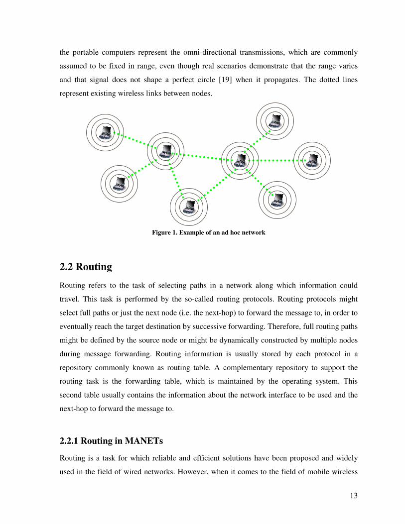
example of an ad hoc network is shown in Figure 1. In Figure 1, the concentric circles around
13
the portable computers represent the omni-directional transmissions, which are commonly
assumed to be fixed in range, even though real scenarios demonstrate that the range varies
and that signal does not shape a perfect circle [19] when it propagates. The dotted lines
represent existing wireless links between nodes.
Figure 1. Example of an ad hoc network
2.2 Routing
Routing refers to the task of selecting paths in a network along which information could
travel. This task is performed by the so-called routing protocols. Routing protocols might
select full paths or just the next node (i.e. the next-hop) to forward the message to, in order to
eventually reach the target destination by successive forwarding. Therefore, full routing paths
might be defined by the source node or might be dynamically constructed by multiple nodes
during message forwarding. Routing information is usually stored by each protocol in a
repository commonly known as routing table. A complementary repository to support the
routing task is the forwarding table, which is maintained by the operating system. This
second table usually contains the information about the network interface to be used and the
next-hop to forward the message to.
2.2.1 Routing in MANETs
Routing is a task for which reliable and efficient solutions have been proposed and widely
used in the field of wired networks. However, when it comes to the field of mobile wireless
14
networks, the routing task becomes more complicated and existing solutions cannot be
applied. Wired network solutions become inefficient, mainly because of their assumptions of
a fixed topology and the use of reliable channels, which contradict the mobile and wireless
characteristics of MANETs. Consequently, routing protocols for MANETs must assume that
nodes do not have a-priori knowledge about the network topology, which has to be
discovered. Therefore, the two main ideas to perform routing in MANETs are either that each
node continuously announces its presence and listens to periodic broadcast announcements
from its neighbors (even if no message is to be transmitted), or that each node looks for a
path to reach a specific destination node only when a message is to be transmitted. These two
ideas give origin to the two main types of routing protocols: proactive and reactive,
respectively, which are explained later on. [17] discusses some of the characteristics of
MANETs that make routing difficult. They are listed next:
• Dynamic topologies which may change randomly and rapidly at unpredictable
times.
• Bandwidth limitations.
• Wireless links of variable capacities, which achieve significantly lower capacity
than wired links.
• Changes on environmental conditions make the achieved throughput much less
than the radio’s maximum transmission rate.
• Low link capacities make congestion a norm rather than an exception when the
MANET is used as an extension of a higher capacity fixed network.
• Energy constrained operation of nodes that rely on exhaustible energy sources
(e.g., batteries).
• Diminished performance when the network size grows, meaning lack of
scalability.
2.2.2 MANET Routing Protocols
Substantial research efforts in the field of routing protocols for ad hoc networks have been
made. Therefore, a large amount of different routing protocols have been proposed. [20]
15
provides an extensive list of them. Depending on the operation idea behind each routing
protocol they can be classified as proactive (table-driven), reactive, (on-demand) or hybrid
(combination of both). Additionally, they can be classified as position-based when supported
by location information to make routing decisions. Each of these classifications is discussed
in the following sections. However, before addressing them, we should comment on the
simplest mechanism to deliver packets to any given destination, which is known as flooding.
Flooding is also a component of many routing protocols (e.g., [21]) and does not require any
topological information. The idea behind flooding is that the source node transmits each data
packet once, and it is retransmitted by each other node in the network, with the hope that it
will eventually reach the destination node. The great disadvantage of flooding is the high
network load that it generates even by single transmission sources. Due to the high traffic
load, several optimizations have been proposed in order to reduce the number of packet
transmissions (e.g., [22]). An important characteristic of simple flooding is that all the traffic
sent into the network is composed of data packets carrying user information without sending
any control packets. Control packets are packets created by each routing protocol to support
its operation, which do not carry any user information at all. Control packets represent an
additional network load. However, their size is usually very small when compared to data
packets.
2.2.2.1 Proactive Protocols
The main idea behind proactive protocols, also known as table-driven protocols, is that each
node periodically announces its presence and it also listens to broadcast announcements from
its neighbors. Each of these broadcasts may contain additional status information about
neighboring nodes or network links in order to support path computation. The collected
information is locally stored and paths to every network destination are locally computed and
available at all times. Therefore, no additional delays are experienced when a routing path is
needed. Some well-know examples of proactive protocols are DSDV [23], TBPRF [3], and
OLSR [2]. As an example we describe OLSR [2]. OLSR is a table-driven, link-state routing
protocol that periodically advertises the links in the network. OLSR optimizes the link
advertisement process by reducing the amount of advertised links and the number of nodes
advertising them. OLSR also optimizes the message broadcasting mechanism by limiting
16
message forwarding to MPRs (Multi Point Relays) only. OLSR nodes become aware of one-
hop and two-hop neighbors by continuously exchanging HELLO messages with the list of
one-hop neighbors. MPR nodes, which optimize broadcasting and support path calculation,
are selected by each node in the network (called MPR Selector) as the minimum set of one-
hop neighbors that allow reaching every two-hop neighbor. MPRs are the only nodes
generating TC messages and also the only ones forwarding them. TC messages advertise the
links between MPRs and MPR Selectors and those links are used by the shortest hop path
algorithm to construct paths reaching every node in the network.
2.2.2.2 Reactive Protocols
The main idea behind reactive protocols, also known as on-demand protocols, is that each
node looks for routing paths only when needed. This process to look for a path to a given
destination is commonly known as route discovery. Therefore, there is some additional
transmission delay that is experienced while the route is discovered, but just by the first few
packets. Some well-known examples of reactive protocols are DSR [4], AODV [1] and
DYMO [5]. As an example we describe DSR [4]. DSR is a reactive algorithm that quickly
adapts to routing changes when node movement is frequent and produces little or no
overhead when nodes move less frequently. In DSR, every source node S wishing to
communicate with any destination node D initiates a Route Discovery process (if no route to
D is available). During route discovery, the source node broadcasts a route request message
targeted to D and every node, other than D, re-broadcasts the message once, while adding its
own ID to the message header. Any route request message that reaches D contains a path
from S to D, which is sent back to S by means of a route reply message that follows the
reverse of the discovered path. Then S sends the data packets to D using the discovered path.
While data packets are being sent, path maintenance is performed. Assuming hop-by-hop
acknowledgements (Acks), when any node does not receive the corresponding Ack, it sends
a route error message to S reporting the link failure. Then, S looks for a different path to D
and all the cached paths using the broken link are truncated at that link. Every node applying
DSR maintains a route cache, where every discovered path is stored for a finite period of
time.
17
2.2.2.3 Hybrid Protocols
Each of the two previous types of protocols is a better match for different scenarios and
provides different advantages and disadvantages. Proactive protocols are known to generate
more overhead, which might be the cause for dropping packets under high network loads.
However, they provide shorter end-to-end delay under light traffic loads and are preferred for
short-lived traffic sessions (no route discovery delay). On the other hand, reactive protocols
are not a good choice for delay-sensitive applications, however they generate less overhead
and usually provide better or similar efficiency for most common scenarios [18]. Therefore,
we can say that the best choice is scenario dependant. Hybrid protocols try to take the best
features of each type and combine reactive and proactive behavior in one single protocol.
Two examples of this type of protocols are ZRP [24] and HSLS [25]. Both of them share the
idea that it is more important to have accurate information about the close neighborhood than
about nodes located at the far distance. As an example we describe ZRP [24]. ZRP divides
the network into overlapping zones and runs different protocols inside and between each
zone. Inside each zone, the intra-zone protocol IARP proactively maintains each node
informed about the zone topology. When the destination node is not located inside the same
zone, the source node initiates a route discovery by using the reactive inter-zone protocol
IERP that sends route request messages to the zone-border nodes, which continue the process
until the destination is found. A key feature of this protocol is the selection of the zone
diameter size, which defines the boundaries between reactive and proactive operation.
2.2.2.4 Position Based Protocols
The last classification for ad hoc routing protocols is position based. Position based protocols
assume that each node is aware of its own location, the location of its neighbors (if beacons
are used) and the location of the destination. Each node forwards each data packet by making
local decisions, always trying to forward the packet to a node closer to the destination than
the current node itself. This kind of protocols relies on a localization technique (e.g., GPS -
global positioning system-) to obtain the location of each node and on a localization service
that distributes the location of each potential destination node to the rest of the network. The
location service accounts for the major fraction of the overhead, therefore, it has to be
efficient. Some well-known position-based protocols are DREAM [26], LAR [27] and GFG
18
[28]. As an example we describe GFG [28]. GFG is a position-based protocol that combines
and switches back and forth between Greedy [28] and FACE [28] protocols. Greedy [28] is a
routing algorithm that achieves high delivery ratios by forwarding packets to the neighbor
that is the closest (in Euclidean distance) to the destination node. However, it does not
guarantee packet delivery. On the other hand, FACE [28] is a routing algorithm that
guarantees packet delivery, but causes large delivery delays. The combination of both
produces a lower delay routing algorithm that guarantees packet delivery. GFG applies
FACE whenever Greedy fails to find a node closer to the destination than the current node
itself, and switches back to Greedy once FACE finds a closer node. FACE performs routing
over a connected planar graph called Gabriel Graph (GG). The GG is extracted from the
network graph, it is locally and independently computed by each node, and partitions the
plane in faces made up of links of the network graph. FACE performs routing by traversing
the faces (using the corresponding network links) that overlap with an imaginary line from
the source to the destination node.
2.2.3 Path Computation Metrics
In all of the previous routing protocols given as example, the topology of the network (full or
partial) is always obtained first (proactively or reactively) and based on it the routing path is
determined. Assuming that the best way to reach a destination node is by taking the shortest
path, the shortest path algorithm, which uses the minimum hop count as its metric, tends to
be the favorite choice. However, [29] shows that such an assumption might not hold under
realistic scenarios where link quality varies drastically. Therefore, additional metrics other
than the minimum number of hops should be used to create more reliable paths. These new
metrics could be based on link status (e.g., link quality, link bandwidth), node status (e.g.,
node energy, buffer size) or network status (e.g., network load) information. [30] discusses
and compares different link-quality metrics. These metrics are: ETX [31] (Expected
Transmission Count), Per-hop Round Trip Time and Per-hop Packet Pair Delay. They are
compared against the minimum hop count metric. In terms of node status information, [32]
proposes to use the transmission power required to transmit each message and the remaining
load battery at each node, as metrics. Therefore, different and even multiple metrics could be
19
combined to determine the best routing paths based on the specific requirements of each
network, and on specific characteristics of the operation environment.
2.2.4 QoS Routing
Most of the routing protocols for ad hoc networks are best-effort protocols. Best-effort means
that there are no guarantees that data will be delivered, or that traffic will be given a certain
priority, or that a certain Quality of Service (QoS) level will be provided. In best-effort
protocols, all of the traffic receives the best possible service but without guaranteeing a fixed
bit rate or delivery time, which depend on the current network load. However, current
applications such as multimedia or voice over IP, require QoS levels that guarantee a
minimum bit rate and data flow priority. Guaranteeing QoS levels in multi-hop ad hoc
wireless networks is very challenging due to channel quality fluctuations, packet contention
on adjacent links, long-range interference and packet collisions. The most commonly used
quality of service metrics in MANETs are: bandwidth, delay and jitter. In order to
incorporate quality of service guarantees in ad hoc routing protocols, some of the existing
protocols have been modified. An example is [33], where a QoS extension for DSR is
proposed. On the other hand, some protocols have been specifically designed with the goal of
providing QoS. That is the case for CEDAR [34] (Core Extraction Distributed Ad hoc
Routing) and TBR [35] (Ticket Based Routing).
2.2.5 Routing Summary
Section 2.2 and its subsections introduced routing in MANETs, discussed its challenges and
reviewed the main types of ad hoc routing protocols. This review, along with the examples of
path computation metrics and the discussion about QoS routing, show a glimpse of the broad
range of design choices for unicast routing protocols. In fact, this range of choices increases
every time that a new protocol feature is proposed. New features translate into new
variabilities that can be further combined to create new routing protocols. Therefore, the
domain of unicast routing protocols provides enough variability to be chosen as the target
domain of GP-Pro.
20
2.3 Literature Review
This review looks into the field of alternative methods to generate software applications
(other than developing from scratch), which can be applied to the generation of routing
protocols. The discussed alternatives are organized, in increasing order, according to the
support that they provide to achieve the generation of complete applications. The first
alternative is the use of libraries that provide a large set of commonly used functions and
methods. The drawback of this approach is that it might not provide methods that are
specialized enough for the desired application domain (the ASL [15] library presented in
Section 2.3.1 is an example). A second alternative for the development of software
applications is the use of frameworks, which, according to [36], are reusable “semi-
complete” applications that can be specialized to produce custom applications. These
frameworks usually define the main software architecture or the interfaces between its
elements, which have to be implemented by every application. Even though frameworks
offer an attractive and faster approach for developing highly specialized applications, there is
still a lot of work that has to be done by the application developer. A third alternative is the
use of component-based software engineering, where existing components, which are mainly
treated as “black boxes”, are used to build the software applications. This approach is very
attractive if enough fine-grained components that can be used to construct a broad range of
applications are available. However, some challenges for this approach still exist, such as the
need for selecting and properly interconnecting the components building the application. One
of the recent and more attractive alternatives is called Generative Programming. Generative
Programming still makes use of components but it is also powered with the knowledge to
automatically select and assemble those components. The selection of components is based
on the user requirements, which are expressed by means of a specification language.
Generative Programming tremendously reduces the development time, and the built-in
knowledge considerably decreases the probability of errors introduced by the software
developers. Generative Programming strongly supports the concept of automatic generation
of applications, given that a language to specify user requirements exists and that the
software generator can understand it. Finally, research projects that make use of specification
languages for automatic code generation, along with existing frameworks for the specialized
area of ad hoc routing protocols are reviewed.
21
2.3.1 Function Libraries
Each programming language provides a set of libraries with implementations of the most
commonly used functions and methods. Those functions and methods are specialized for the
same domain that the programming language targets, which tends to be somehow generic.
Therefore, it is not common to find libraries that are specialized enough for a specific
domain. Looking at function libraries for the domain of ad hoc routing protocols we find
ASL [15] (Ad hoc Support Library). ASL supports the implementation of reactive protocols.
Reactive protocols require intercepting packets at the kernel-level for packets with no routing
path towards the destination; otherwise, such packets would be dropped and never delivered.
To avoid modifications at the kernel-level and the need to recompile the kernel, a small
loadable kernel module is used to provide kernel interaction. ASL is provided as a user-space
library. ASL provides useful functions, but is only helpful when developing reactive
protocols.
2.3.2 Frameworks
A framework is defined in [36] as a reusable “semi-complete” application that can be
specialized to produce custom applications. [37] says that it is a partially complete software
system that is intended to be instantiated, which defines the architecture for a family of
systems and provides the basic building blocks to create them. It also defines the places
where adaptations for specific functionality should be made. In contrast to earlier object-
oriented reuse techniques based on class libraries, frameworks target particular business units
and application domains. Their benefits come from the modularity, reusability, extensibility
and inversion of control they provide to developers. Encapsulating implementation details
behind interfaces provides modularity, which helps to improve software quality by localizing
maintenance and design modifications. Frameworks enhance reusability by providing generic
components that can be reused to create new applications. These generic components
encapsulate the knowledge of experienced developers and avoid re-creating and revalidating
common solutions. Providing hook methods that allow applications to expand a framework’s
stable interfaces enhances extensibility. The inversion of control at run-time allows the
framework (e.g., Netfilter [38]) to determine which application methods should be invoked in
22
response to external events. Finally, the main objective of frameworks is the acceleration and
the cost-reduction of the development process. However, beyond all those advantages,
frameworks face challenges such as portability among multiple platforms, rejection from
software developers and lack of specialization for more complex domains.
Regarding available techniques to extend frameworks, they can be classified into
white-box and black-box frameworks. White-box frameworks rely on object-oriented
language features such as inheritance and dynamic binding to achieve extensibility. In
contrast, black-box frameworks support extensibility by defining interfaces for components
that can be plugged via object composition. Black-box frameworks are easier to use but
harder to develop because components have to anticipate a wide range of possibilities.
The most common type of framework is the one based on object-oriented
technologies. Object-oriented application frameworks have been used for years. One example
is the X-kernel [11], which is an operating system architecture for constructing and
composing network protocols. The X-kernel integrates the following features: 1) a uniform
set of abstractions for encapsulating protocols, 2) structured abstractions for the most
common patterns of interaction, and 3) support for primitive routines that are applied to
common protocol tasks. The X-kernel views a protocol as a specification of a communication
abstraction through which collections of participants exchange a set of messages. The main
advantages of the X-kernel are that the architecture simplifies the process for implementing
protocols in the kernel and that the kernel can be configured with only those protocols
needed by the application. Every X-kernel configuration contains one protocol for each layer
of the protocol stack. Each protocol is implemented by the user as a collection of C source
files, and the implementation has to comply with the abstractions or interfaces that allow
interaction between protocols. X-kernel is not specialized for any kind of communication
protocols. Therefore, the lack of specialization is reflected by the fact that the whole protocol
has to be implemented by the user and has to match with the layer interaction rules.
ACE [12] (Adaptive Communication Environment) is another object-oriented
framework, whose main objective is to be cross-platform. It targets high-performance and
23
real-time communication services and applications. ACE is written in C++ and provides a set
of reusable wrappers and components that help developers navigate between the limitations
of inflexible and non-portable low-level native OS (Operating System) APIs (Application
Programming Interfaces), and inefficient and unreliable higher-level middleware. The
components in ACE provide implementations of common communication tasks (e.g.,
connection establishment, service initialization, IPC, synchronization, etc.). ACE also
provides a standard library of distributed services that are packaged as self-contained
components, which demonstrate common use-cases and provide reusable implementations of
common distributed application tasks (e.g., naming, synchronization). In summary, ACE
provides multiple aids to implement cross-platform communication protocols. But, still the
implementation has to be done by the user.
Another cross-platform framework that provides an API (Application Programming
Interface) and its own model to implement communication protocols is XORP [39]
(eXtensible Open Router Platform). XORP aims to bridge the gap between network research
and Internet practice by providing a software platform where communication protocols can
be implemented. This platform also allows protocols to be used as the core of practically any
router that can be incorporated into operational networks. XORP aims to integrate the
developed protocols into operational networks, but again, the protocols have to be manually
implemented by the user.
2.3.3 Component-Based Software Engineering
A step forward towards generating complete applications is the assembly of fully functional
components. Component-based software engineering (CBSE) relies on software reuse and
emphasizes on the decomposition of systems into functional components with well-defined
interfaces. Such interfaces are used for communication with other components. Components
are considered much more abstract structures than objects because instead of sharing states,
they communicate exchanging messages. Therefore, when systems based on components are
constructed, components are treated as “black boxes”. When using components, two features
become very important. The first of them is the level of granularity. In general, fine
granularity of components allows higher reusability than coarse granularity, achieving a
24
larger number of different combinations and different systems. The second feature is the
design of interfaces between components, which also defines the way that components
interact. Actually, there exist programming languages like Midas [40] which have been
specifically designed to define the styles of interaction between components. Once the
components are available, they can be configured and plugged together (e.g. using visual
tools or mark-up languages), to create new applications.
[41] examines the usefulness of component-based software engineering for the
implementation of software communication systems and explores visual programming as a
feasible and rapid prototyping alternative for network protocols. [41] makes use of Java
Beans as components and Visual-Age for Java as the visual tool for specification and
configuration of components. Events connect Java Beans, meaning that events trigger events
on some other beans. The main goal is flexibility to build a variety of protocols out of
existing components. Once the Java Beans are available, protocols are built by connecting
components and setting up some of their features using the drag-and-drop graphical interface.
The authors identify granularity and interface design as the most important issues to achieve
flexibility, and suggest that to achieve reusability, components must be largely de-coupled
and autonomous. Fine-granularity components simplify implementation and achieve higher
reuse. Coarse-granularity components built from a set of fine-granularity components are
rarely reused. The architecture presented in [41] supports re-use and introduces a visual tool
for component assembly. However, the implemented protocols have to be run on top of a
proprietary runtime system that does not match with the commonly used layered protocol
stack, meaning lack of compatibility. Additionally, no performance results of any
implemented protocol are provided, which forbids the verification of the architecture
contributions.
Another well known architecture based on components is the Click router [23]. Click
is an architecture for building flexible and configurable routers. Every router is assembled
from packet processing modules called elements, which perform simple functions like
classification, queuing and scheduling. Therefore, a Click router may be represented as a
directed graph with elements as vertices and packets traveling along the edges. Each element
25
inside a router is a C++ object. The router configurations are created using the Click
language, which creates elements and defines how to interconnect them. Either an in-kernel
driver or a user-level driver can run Click configurations in Linux. Because each element is a
packet processor, if a routing table is required (routing tables do not process packets by
themselves), it is encapsulated inside the element making the routing decisions. The same
applies to any other algorithm performing tasks different from packet processing. Some of
the most common ad hoc routing protocols have been implemented using Click, such as:
DSR [42], OLSR [43] and DSDV [44]. However, due to the packet processing nature of the
Click components, the entire routing protocols have to be implemented inside only one or
two components, meaning that no modularity for their implementation is supported, and the
whole protocol implementation has to be performed by the user.
In the specific domain of ad hoc routing protocols, another research project attempts
to create routing protocols by assembling components: the Component-Based Routing (CBR)
[45]. CBR is inspired by the fact that protocol performance changes and even degrades with
changes on the environmental conditions and that the current research efforts have not been
able to explain the performance differences between existing protocols. CBR provides a
collection of elementary modules with various capabilities, limitations and efficiency that
support adaptation and can be manually combined. The objective is to fully understand the
impact of each component on the performance of the entire protocol and to understand when
and why the protocol works well over different operating environments. The ultimate goal of
the project is to systematically design a set of routing protocols that are specifically designed
to operate under rough military conditions (network security is one of the main concerns).
However, CBR does not consider automatic assembly of components nor does it provide a
mechanism for protocol specification, which GP-Pro does. Actually, if the CBR components
were ready and available to the research community, it could be a complementary effort
beneficial to GP-Pro.
2.3.4 Generative Programming
PIX [13] is the first attempt to use GP in network protocol development. PIX is a framework
to generate protocol stacks that attempts to solve the problem of reprogramming similar
26
protocol behaviors at different layers of the protocol stack and the problem of combining
good solutions, proposed by different frameworks, to solve complementary concerns. PIX
was inspired by the X-Kernel [11]. Therefore, it models families of telecommunication
protocol stacks by using abstractions of the same protocol components proposed by the
former (session, protocol, participant, map, message, event and union interface). During the
implementation process, components with parameters are represented by C++ class
templates. The assembly of any specific protocol results from the composition of a series of
components and the information provided by the configuration repository. The output
provided by PIX is not the fully implemented protocol; instead it is a prototype with the PIX
architecture related code for the desired protocol. The generated code requires to be
complemented with the specific functionalities (e.g., message interpretation rules) of each
communication protocol in order to obtain a fully functional version. [46] uses the File
Transfer Protocol (FTP) to compare the performance of PIX and the X-kernel in terms of
latency, throughput, CPU time and memory usage. Results show very light additional
measurable cost experienced by PIX. These results encourage the use of Generative
Programming due to its high degree of configurability. In terms of ad hoc routing protocols,
an implementation of DSR with IPv4 using PIX is available in [47]. In this implementation, a
route discovery is initiated for each session and there is no interaction with the OS kernel.
The increased interest on accelerating software development procedures in general,
while building bug-free applications that reuse previous solutions and that are easy to
maintain, has brought into picture several development paradigms. Generative Programming
is one of them and perhaps the most promising in concept. However, another approach which
is very close to Generative Programming is Model Driven Development (MDD) [48, 49],
which attempts to fully capture the most important properties of software systems through
models. These models are abstract representations of the system and its environment of
interaction. The advantage of MDD is that its models can be compiled into implementation
code that can be deployed. Lately, MDD models have been represented by DSLs, a fact that
narrows the gap between GP and MDD. As the author of [48] explains, the main difference
between MDD and GP is the focus of GP on system families, which is not the case for MDD.
The advantage of this similarity is that MDD tools can be utilized for GP projects. An
27
important example of such a tool is the oAW (OpenArchitectureWare) framework [50],
which has been widely adopted by the software development community.
2.3.5 Automatic Code Generation
As mentioned above, when automatic protocol generation is the goal, a code generator that
takes the protocol specification in the corresponding DSL format as an input is required.
Different combinations of tools and programming languages have been explored. Some of
them are discussed next.
The work presented in [51] does not focus on the generation of source code for
communication protocols. However, the approach taken could be transparently applied and
that is why it is discussed here. [51] presents an automatic multi-output generator based on
XML (eXtensible Markup Language). The output is not only constrained to code generation,
it also generates user information in HTML (Hypertext Markup Language) format. The
objective is to model intelligent instruments. From a graphical modeling of the intelligent
instrument, a global generic device description file is manually created in XML format (the
specification). The XML file can be easily transformed into any other type of file (e.g.
HTML, C, C++, Java) by applying a set of transformation rules. These rules are expressed by
using the XSLT (eXtensible Stylesheet Language Transformation) and are stored in XSL
(eXtensible Stylesheet Language) files. Each XSL file appears almost as a conventional file
written in the target transformation language. For example, an XSL file dedicated to
transforming an XML file into a C++ file is essentially C++ source code. This approach
allows specification independency from the target implementation language, meaning that if
an XML file represents the instrument, source code for any implementation language can be
created if the corresponding XSL transformation file is generated. The XML description is a
listing of the services provided by the instrument. Each service is associated with a piece of
C code that is loaded from a library by an XSLT transformer. This approach could be easily
applied to communication protocols, as done in [52], which generates protocols out of a
specification in XML. In this case, the source code is the only output. In [52], XML is used
to manually create the specification of protocols described through Finite State Machines
(FSMs) and XLST is used to transform the specification into Java source code. Interestingly,
28
[52] suggests that protocol specifications in XML could be easily distributed over a network,
so that code could be automatically generated at a remote network node. This approach could
be useful for distributing new versions of any protocol over an existing network.
In the literature, there is a lot of work in the area of verification and automatic
generation of security protocols. An example of it is [53], which presents a project that
explores the following three areas of automatic generation: specification generation, protocol
verification and implementation (code generation). In [53], the protocol generator provides a
GUI for the user to define desired security properties and system requirements. Once the
input has been provided, the protocol space is explored to find all possible protocols and a
protocol screener is used to verify that the security properties are satisfied. Finally, the code
generator translates the protocol specifications into an internal data structure, which is
translated again to produce the source code. The code generator generates a Java class file
implementing the party's actions for each party of the security protocol.
GP-Pro aims to generate routing protocols for ad hoc networks from a user
specification while providing its own specification language and the entire protocol
generator. Two other projects, which also provide its own specification language and are also
oriented towards fast prototyping are OverML (Overlay Modeling Language) [54] and P2
[55]. However, both of them are applied to the domain of overlay networks. An overlay
network is a network built on top of another network, where nodes can be thought of as being
connected by virtual or logical links in the underlying network. Each of these links might
correspond to a path, perhaps built by many physical links. Both projects treat the network as
a distributed database where the nodes act as information repositories that are queried by the
overlay network to achieve specific tasks. Each project provides its own specification
language, and both of them are similar to a database query language. Additionally, both
projects provide a downloadable version to try out, but in a very early development stage
(alpha and sub-alpha versions, respectively). Due to goal similarities between these two
projects and GP-Pro, the possibility to adapt any of them to the domain of MANET routing,
in order to reuse the specification languages or the implementation tools, was analyzed.
However, the difference with respect to the target domains, and the fact that the main
29
challenges for overlay networks focus on network topology selection and maintenance, rather
than on path determination, limits a possible adaptation of the aforementioned projects to our
target domain. Therefore, the reuse of P2 or OverML to create GP-Pro would not be
transparent and significant effort would be required without any guarantees that all the
particular features of routing protocols for MANETs could be supported. Actually, the
outcomes of P2 and OverML (meaning the generated overlay networks), both require to be
run on top of a proprietary runtime system (because the output is not source code ready for
deployment), which does not match with our goal of generating protocols ready for
deployment. Consequently, we concluded that no real benefits could be obtained by reusing
P2 or OverML, so, we proceeded with the design of GP-Pro based on Generative
Programming.
2.3.6 Frameworks for Ad Hoc Routing Protocols
After reviewing the different alternatives that are available to automatically generate
communication protocols, we next review the alternatives that are specially designed for ad
hoc routing protocols, which are actually scarce.
A portable, user-level framework for ad hoc routing written in C++ is proposed in
[56]. The authors make use of a SOCKS proxy that handles client requests and then uses an
implementation of an ad hoc routing protocol at the application layer to provide routing.
Implementations of DSR and flooding are discussed. The framework also provides an
integrated simulator that allows new routing protocols to be tested and the code moved to
production deployment without further modifications. The only requirement is that the
implementation be linked with a routing environment such as SOCKS. The objectives of the
framework are rapid implementation and testing over the integrated simulator. Reduced
configuration, portability between different operating systems and Internet connectivity are
also part of the goals for the routing protocol. The authors claim that testing on Windows
laptops was successfully done, but no performance study is presented. This framework seems
to be very useful for testing purposes; however, in terms of the mechanisms or tools to
implement each routing protocol, the framework does not provide many. It only forces the
30
routing protocol to implement a routing interface for message handling, and the entire routing
protocol has to be implemented by the user.
The interest shown in [56] to use the same implementation source code for simulation
and for the actual protocol deployment on a real network is shared by [57] and [58]. [57]
investigates how to port a deployable implementation of AODV for real networks to the
well-known network simulator NS-2 [59]. [57] identifies the modifications that have to be
made to the deployable source code along with the additions to be made to NS-2 in the form
of patches. Therefore, additional deployable implementations of ad hoc routing protocols
could be simulated in NS-2 by using [57] as guideline. In fact, [60] provides a deployable
implementation of DYMO [5] called DYMOUM that can be simulated in NS-2 as well,
which follows the same approach. On the other hand, [58] initiates the migration of a
protocol implementation from the NS-2 end towards the deployable version. [58] provides a
system environment called PRAN (Physical Realization of Ad hoc Networks), where NS-2
implementations of ad hoc routing protocols can run unmodified at the user-level as long as
the simulation code implements specific programming interfaces that are claimed to be a
normal part of NS-2. [58] discusses the modifications to be made to the operating system
kernel in order to support PRAN using Linux and FreeBSD (Free Berkeley Software
Distribution) kernels as examples. The authors claim that PRAN is easy to port across
multiple operating systems, including Windows.
2.4 Summary
This chapter provided the background in the two main fields addressed by this research
document which are: routing in ad hoc networks, and the existing alternatives to support the
implementation of ad hoc routing protocols. We introduced the concept of MANETs along
with their particular characteristics. We also discussed routing and its challenges in the
MANET domain and the classification of routing protocols, along with protocol examples. In
terms of tools to support the development of communication protocols, we described the
main development approaches, which are either based on libraries, frameworks or
components. Or, on the software generation paradigm called Generative Programming that
31
we propose to be used for the generation of ad hoc routing protocols. From this review we
notice that most of the alternatives are oriented to very general domains without real
specialization, which limits the provided support. On the other hand, in regards of the
specific domain of MANET routing, the only tool available is the ASL [15] library.
However, it only provides support for one type of routing protocol, the reactive type.
Therefore, the innovative contribution of GP-Pro is to apply Generative Programming to the
specific domain of MANET routing, in order to provide generation support for ad hoc
routing protocols. It does so as a protocol generator that can assemble existing components
according to a user specification, and that also aims to generate full protocol
implementations. Such a generator also allows to be further extended to keep up with the
evolution of the target domain along with its forthcoming requirements.
32
Chapter 3
Domain Analysis
The previous chapter presented a comprehensive literature review about supportive tools and
mechanisms to accelerate the development of communication protocols, existing approaches
to automate code generation, and, more importantly, the related work strictly focused on
routing protocols for ad hoc networks. Next, we have to identify the protocols to be
generated by GP-Pro along with their commonalities and variabilities. As mentioned before,
the way to do so is by performing a Domain Analysis. Such a domain analysis is presented in
this chapter after Generative Programming is introduced. To identify the commonalities and
variabilities of the target protocols, most of the well-know protocols were considered (e.g.,
DSR [4], AODV [1], OLSR [2], DYMO [5], etc) along with some other protocols presented
in several surveys (e.g., [61, 62]).
3.1 Introduction to Generative Programming
Generative Programming addresses the automatic selection and assembly of components on
demand. It is a response to the fact that the current object-oriented technology does not
support reuse and configurability in an effective way. The use of a system family approach
instead of the one-of-a-kind approach supports the creation of reusable components. The
assembly of components is automated based on configuration knowledge. Component-based
software engineering current practice generates software from components too. However, the
selection of the right components and their interconnection has to be manually performed.
These tasks might require a lot of effort from the user, especially when the chosen
components are not a perfect fit and component adaptation is required. GP intends that the
programmer only states what she/he wants in abstract terms and the generator produces the
desired system. However, this scheme only works if the components are designed to fit a
33
common architecture and if the configuration knowledge to translate abstract requirements
into sets of components is built-in inside the generator.
To support Generative Programming and to produce reusable components, it is
necessary to focus on families of systems rather than single systems. The author in [63] states
that a set of programs constitutes a family whenever it is worthwhile to study programs from
the set by first studying the common properties of the set and then determining the special
properties of the individual family members. The domain analysis presented in this chapter,
which is performed for the domain of ad hoc routing protocols, identifies these
commonalities and variabilities that support the design of GP-Pro. In order to produce the
software components, there is a need to differentiate between development for reuse, better
known as Domain Engineering, and with reuse, better known as Application Engineering.
Application Engineering focuses on a single system rather than a system family. It develops
software products from reusable software components created by the domain engineering
process and provides feedback to improve their reusability. Domain engineering [64] is
concerned with the development of the reusable assets (e.g., components), and is the process
to follow in order to create application families. Increased productivity is the main reason for
doing domain engineering. Domain analysis, domain design and domain implementation are
the steps that compose domain engineering.
Domain analysis involves domain scoping and feature modeling. Domain scoping
identifies which systems belong to the family and which do not. The outcome of this step is
often referred to as a product line. On the other hand, feature modeling identifies all the
commonalities and variabilities across the domain. The commonalities represent the potential
savings or productivity increase. Commonalities mean standardizing, which promotes
increased productivity and efficiency. However, the negative aspect of commonalities is that
each of them may constrain or shrink the size of the family. On the other hand, the
variabilities represent the features that change between the family members. Variabilities
promote variation and larger product families. The second phase of domain engineering,
called domain design, focuses on the development of a common architecture for the system
34
family. Finally, domain implementation is the creation of components and tools (e.g., the
actual application generator) to generate the customized applications in the domain.
Once the components have been generated throughout the domain engineering
process, the mapping from the abstract user requirements to the assembly of the right set of
components has to be performed. This assembly process is to be automated and the
configuration knowledge, which maps between problem and solution space, is the key. The
problem space consists of the application-oriented concepts and features used by the
programmers to express their needs. The solution space consists of the implementation
components and all of their possible combinations. The configuration knowledge consists of
default settings, default dependencies, illegal feature combinations and construction rules and
it is implemented using generators.
However, to achieve automatic protocol generation using Generative Programming,
additional generation elements are required. First, a DSL or a visual tool to allow user
specifications is required. Second, a code generator is needed that takes the protocol
specification in the corresponding DSL as an input, and returns the source code as an output.
Finally, the generated code should be compiled with the corresponding compiler (language
and platform dependant) in order to be deployed. Furthermore, the availability of an
automatic protocol verifier (e.g., [65, 66]) to check the correct functionality of the generated
protocols could be a valuable addition. However, protocol verification is a separate and
challenging field of research on its own.
3.2 Domain Architecture
The domain architecture is the outcome of the domain design phase, and represents the
common underlying architecture of unicast routing protocols for IP based mobile ad hoc
networks. GP-Pro envisions the generation of proactive, reactive and position-based
protocols. The domain architecture is shown in Figure 2 and it is modeled by abstractions
(that we refer to as components) for collecting, distributing, storing and processing routing
information that is utilized to determine the “best” existing path towards any routing
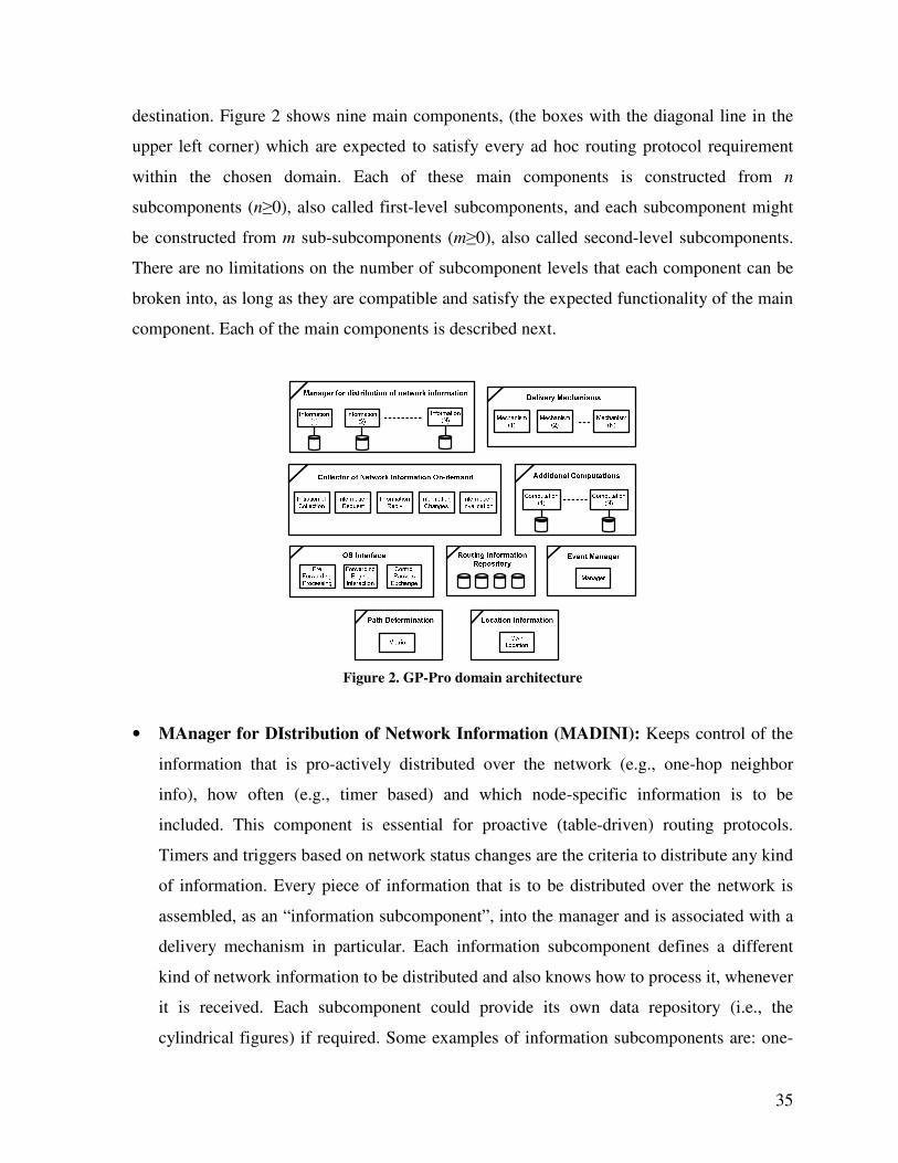
35
destination. Figure 2 shows nine main components, (the boxes with the diagonal line in the
upper left corner) which are expected to satisfy every ad hoc routing protocol requirement
within the chosen domain. Each of these main components is constructed from n
subcomponents (n≥0), also called first-level subcomponents, and each subcomponent might
be constructed from m sub-subcomponents (m≥0), also called second-level subcomponents.
There are no limitations on the number of subcomponent levels that each component can be
broken into, as long as they are compatible and satisfy the expected functionality of the main
component. Each of the main components is described next.
Figure 2. GP-Pro domain architecture
• MAnager for DIstribution of Network Information (MADINI): Keeps control of the
information that is pro-actively distributed over the network (e.g., one-hop neighbor
info), how often (e.g., timer based) and which node-specific information is to be
included. This component is essential for proactive (table-driven) routing protocols.
Timers and triggers based on network status changes are the criteria to distribute any kind
of information. Every piece of information that is to be distributed over the network is
assembled, as an “information subcomponent”, into the manager and is associated with a
delivery mechanism in particular. Each information subcomponent defines a different
kind of network information to be distributed and also knows how to process it, whenever
it is received. Each subcomponent could provide its own data repository (i.e., the
cylindrical figures) if required. Some examples of information subcomponents are: one-
36
hop neighbors, known links in the network, node-specific information such as battery
power, or link-specific information such as link quality.
• Delivery mechanisms: Defines the mechanisms that can be used to forward any control
packet that is ready for transmission. The range of options goes from one hop
transmission and simple flooding to more efficient mechanisms such as multipoint relays
[2] or dominating sets [67], where only a pre-computed set of nodes retransmits each
message. Unicasting can be also used in some scenarios.
• COllector of Network Information on-demand (CONI): This component mainly
resembles the route discovery process of on-demand routing protocols but it is more
general. Its function is to obtain different kinds of information that might be needed by
the protocol and that are expected to be available somewhere in the network. It is
essentially composed of five subcomponents which are: 1) Initiation of information
collection (e.g., Initiation of Route Discovery), 2) Information Request (e.g., Route
Request), 3) Information Reply (e.g., Route Reply), 4) Notification of changes on
collected information (e.g., Route Error), 5) Total invalidation of collected information
(e.g., Route Erasure [68]). This component is essential for reactive (on-demand)
protocols.
• Additional computations: Different routing protocols might make use of very particular
computations or algorithms to perform tasks that are essential for them. These
computations can be called by any component or subcomponent at any time or can be
scheduled to run at specific time intervals. Each additional computation subcomponent
might provide its own data repository (i.e., the cylindrical figures) if required. Algorithms
to compute distribution structures such as MPRs [2] or dominating sets [67] exemplify
the subcomponents building this component.
• Operating system interface: This component provides an interface between the routing
protocol and the operating system. It allows interaction with the forwarding engine of the
OS; provides the functionality for processing packets before they reach the OS
37
forwarding engine (pre-forwarding processing); and supports the exchange of control
packets. Pre-forwarding processing is required by protocols that do not maintain an
updated routing table and require initiating a protocol process whenever a packet is ready
for transmission or by protocols that require performing special packet header processing
(e.g., DSR [4]). It applies to reactive and position-based protocols.
• Path determination: Depending on the applied mechanism to collect network
information, this component either computes (from stored information) or selects (from
multiple route replies) a route towards a particular network node. Different metrics can be
applied to determine the “best” path towards the destination node. Some examples of
metrics are Minimum Hop Count, ETX [31], power-based metrics [67], geographic
progress [28], etc. Therefore, path determination depends on the chosen metric. Path
determination is not particular to proactive protocols; reactive protocols use it as well.
Depending on the kind of protocol, a routing table may be continuously updated.
• Routing Information Repository (RIR): Its function is to store the data particular to the
operation of the routing protocol. The RIR is designed to host all of the different data
repositories used by the different components building the routing protocol. It resembles
a database that stores multiple data tables. It also provides generic methods, available to
every routing component, to process queries aimed to retrieve, insert, update or delete
data entries from any of the repositories. Each of these repositories is assembled as a RIR
subcomponent and each of them provides the names and types of its data fields.
• Event manager: The event manager provides a mechanism for scheduling tasks that are
launched after a certain period of time such as the distribution of network information
messages (at periodic intervals), performing any of the periodic additional computations,
or expiring soft states (e.g., route discovery, routing table entry).
• Location information: The location component is in charge of providing the location
information of the node itself. The location information can be obtained by any absolute
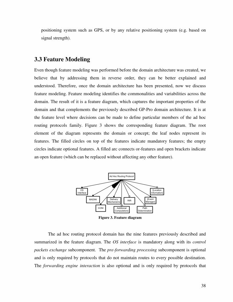
38
positioning system such as GPS, or by any relative positioning system (e.g. based on
signal strength).
3.3 Feature Modeling
Even though feature modeling was performed before the domain architecture was created, we
believe that by addressing them in reverse order, they can be better explained and
understood. Therefore, once the domain architecture has been presented, now we discuss
feature modeling. Feature modeling identifies the commonalities and variabilities across the
domain. The result of it is a feature diagram, which captures the important properties of the
domain and that complements the previously described GP-Pro domain architecture. It is at
the feature level where decisions can be made to define particular members of the ad hoc
routing protocols family. Figure 3 shows the corresponding feature diagram. The root
element of the diagram represents the domain or concept; the leaf nodes represent its
features. The filled circles on top of the features indicate mandatory features; the empty
circles indicate optional features. A filled arc connects or-features and open brackets indicate
an open feature (which can be replaced without affecting any other feature).
Ad Hoc Routing Protocol
OS
Interface
MADINI Delivery
Mechanisms
CONI Additional
Computations
Path
Determination
RIR[Event
Manager]
[Location
Information]
Figure 3. Feature diagram
The ad hoc routing protocol domain has the nine features previously described and
summarized in the feature diagram. The OS interface is mandatory along with its control
packets exchange subcomponent. The pre-forwarding processing subcomponent is optional
and is only required by protocols that do not maintain routes to every possible destination.
The forwarding engine interaction is also optional and is only required by protocols that
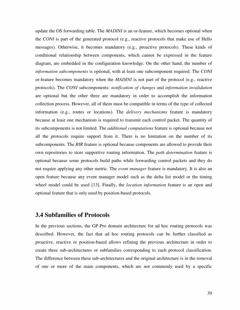
39
update the OS forwarding table. The MADINI is an or-feature, which becomes optional when
the CONI is part of the generated protocol (e.g., reactive protocols that make use of Hello
messages). Otherwise, it becomes mandatory (e.g., proactive protocols). These kinds of
conditional relationship between components, which cannot be expressed in the feature
diagram, are embedded in the configuration knowledge. On the other hand, the number of
information subcomponents is optional, with at least one subcomponent required. The CONI
or-feature becomes mandatory when the MADINI is not part of the protocol (e.g., reactive
protocols). The CONI subcomponents: notification of changes and information invalidation
are optional but the other three are mandatory in order to accomplish the information
collection process. However, all of them must be compatible in terms of the type of collected
information (e.g., routes or locations). The delivery mechanisms feature is mandatory
because at least one mechanism is required to transmit each control packet. The quantity of
its subcomponents is not limited. The additional computations feature is optional because not
all the protocols require support from it. There is no limitation on the number of its
subcomponents. The RIR feature is optional because components are allowed to provide their
own repositories to store supportive routing information. The path determination feature is
optional because some protocols build paths while forwarding control packets and they do
not require applying any other metric. The event manager feature is mandatory. It is also an
open feature because any event manager model such as the delta list model or the timing
wheel model could be used [13]. Finally, the location information feature is an open and
optional feature that is only used by position-based protocols.
3.4 Subfamilies of Protocols
In the previous sections, the GP-Pro domain architecture for ad hoc routing protocols was
described. However, the fact that ad hoc routing protocols can be further classified as
proactive, reactive or position-based allows refining the previous architecture in order to
create three sub-architectures or subfamilies corresponding to each protocol classification.
The difference between these sub-architectures and the original architecture is in the removal
of one or more of the main components, which are not commonly used by a specific
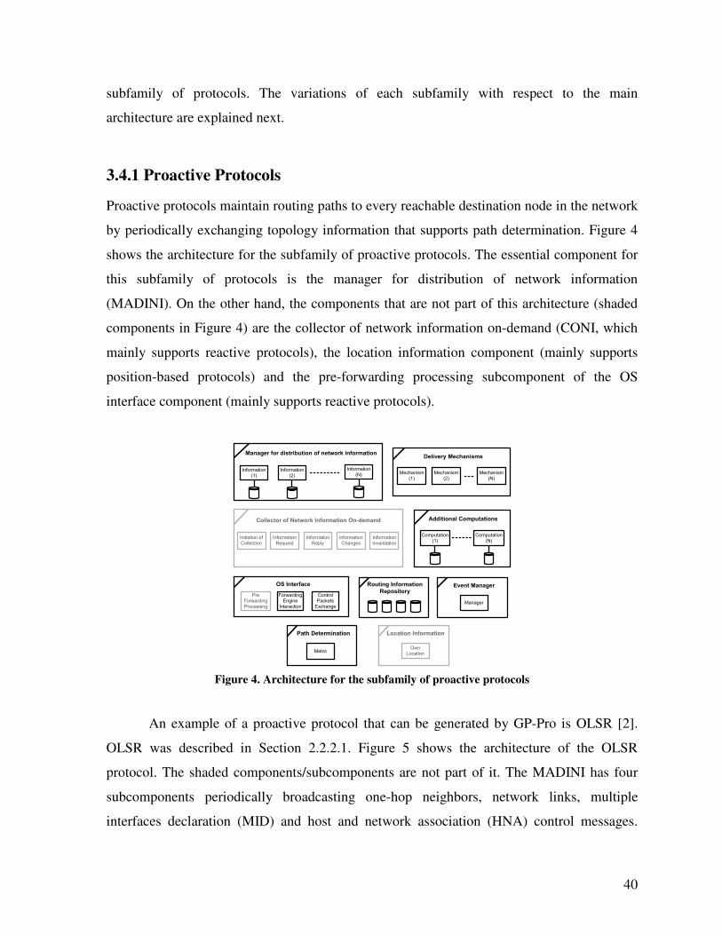
40
subfamily of protocols. The variations of each subfamily with respect to the main
architecture are explained next.
3.4.1 Proactive Protocols
Proactive protocols maintain routing paths to every reachable destination node in the network
by periodically exchanging topology information that supports path determination. Figure 4
shows the architecture for the subfamily of proactive protocols. The essential component for
this subfamily of protocols is the manager for distribution of network information
(MADINI). On the other hand, the components that are not part of this architecture (shaded
components in Figure 4) are the collector of network information on-demand (CONI, which
mainly supports reactive protocols), the location information component (mainly supports
position-based protocols) and the pre-forwarding processing subcomponent of the OS
interface component (mainly supports reactive protocols).
Manager for distribution of network information
Information
(1)
Delivery Mechanisms
Mechanism
(1)
Information
(2)
Information
(N) Mechanism
(2)
Mechanism
(N)
Additional Computations
Computation
(1)
Computation
(N)
Collector of Network Information On-demand
Initiation of
Collection
Information
Request
Information
Reply
Information
Changes
Information
Invalidation
OS Interface
Forwarding
Engine
Interaction
Pre
Forwarding
Processing
Control
Packets
Exchange
Event Manager
Manager
Path Determination
Metric
Routing Information
Repository
Location Information
Own
Location
Figure 4. Architecture for the subfamily of proactive protocols
An example of a proactive protocol that can be generated by GP-Pro is OLSR [2].
OLSR was described in Section 2.2.2.1. Figure 5 shows the architecture of the OLSR
protocol. The shaded components/subcomponents are not part of it. The MADINI has four
subcomponents periodically broadcasting one-hop neighbors, network links, multiple
interfaces declaration (MID) and host and network association (HNA) control messages.
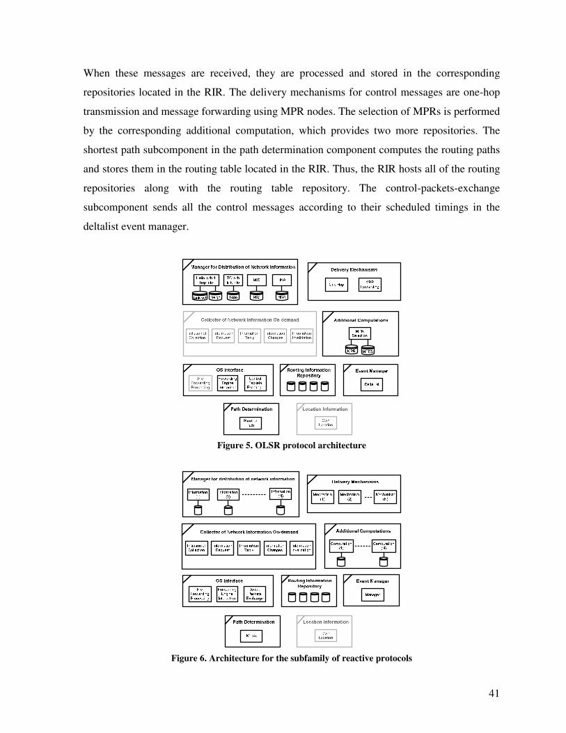
41
When these messages are received, they are processed and stored in the corresponding
repositories located in the RIR. The delivery mechanisms for control messages are one-hop
transmission and message forwarding using MPR nodes. The selection of MPRs is performed
by the corresponding additional computation, which provides two more repositories. The
shortest path subcomponent in the path determination component computes the routing paths
and stores them in the routing table located in the RIR. Thus, the RIR hosts all of the routing
repositories along with the routing table repository. The control-packets-exchange
subcomponent sends all the control messages according to their scheduled timings in the
deltalist event manager.
Figure 5. OLSR protocol architecture
Figure 6. Architecture for the subfamily of reactive protocols
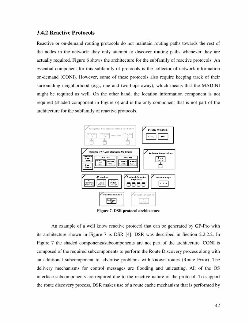
42
3.4.2 Reactive Protocols
Reactive or on-demand routing protocols do not maintain routing paths towards the rest of
the nodes in the network; they only attempt to discover routing paths whenever they are
actually required. Figure 6 shows the architecture for the subfamily of reactive protocols. An
essential component for this subfamily of protocols is the collector of network information
on-demand (CONI). However, some of these protocols also require keeping track of their
surrounding neighborhood (e.g., one and two-hops away), which means that the MADINI
might be required as well. On the other hand, the location information component is not
required (shaded component in Figure 6) and is the only component that is not part of the
architecture for the subfamily of reactive protocols.
Figure 7. DSR protocol architecture
An example of a well know reactive protocol that can be generated by GP-Pro with
its architecture shown in Figure 7 is DSR [4]. DSR was described in Section 2.2.2.2. In
Figure 7 the shaded components/subcomponents are not part of the architecture. CONI is
composed of the required subcomponents to perform the Route Discovery process along with
an additional subcomponent to advertise problems with known routes (Route Error). The
delivery mechanisms for control messages are flooding and unicasting. All of the OS
interface subcomponents are required due to the reactive nature of the protocol. To support
the route discovery process, DSR makes use of a route cache mechanism that is performed by
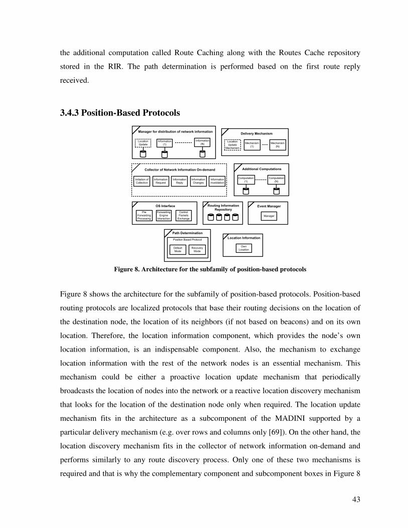
43
the additional computation called Route Caching along with the Routes Cache repository
stored in the RIR. The path determination is performed based on the first route reply
received.
3.4.3 Position-Based Protocols
Manager for distribution of network information
Location
Update
Delivery Mechanism
Location
Update
Mechanism
Additional Computations
Computation
(1)
Information
(1)
Information
(N) Mechanism
(1)
Mechanism
(N)
Computation
(N)
Collector of Network Information On-demand
Initiation of
Collection
Information
Request
Information
Reply
Information
Changes
Information
Invalidation
Event Manager
Manager
Routing Information
Repository
Position Based Protocol
Default
Mode
Recovery
Mode
Path Determination
OS Interface
Forwarding
Engine
Interaction
Pre
Forwarding
Processing
Control
Packets
Exchange
Location Information
Own
Location
Figure 8. Architecture for the subfamily of position-based protocols
Figure 8 shows the architecture for the subfamily of position-based protocols. Position-based
routing protocols are localized protocols that base their routing decisions on the location of
the destination node, the location of its neighbors (if not based on beacons) and on its own
location. Therefore, the location information component, which provides the node’s own
location information, is an indispensable component. Also, the mechanism to exchange
location information with the rest of the network nodes is an essential mechanism. This
mechanism could be either a proactive location update mechanism that periodically
broadcasts the location of nodes into the network or a reactive location discovery mechanism
that looks for the location of the destination node only when required. The location update
mechanism fits in the architecture as a subcomponent of the MADINI supported by a
particular delivery mechanism (e.g. over rows and columns only [69]). On the other hand, the
location discovery mechanism fits in the collector of network information on-demand and
performs similarly to any route discovery process. Only one of these two mechanisms is
required and that is why the complementary component and subcomponent boxes in Figure 8
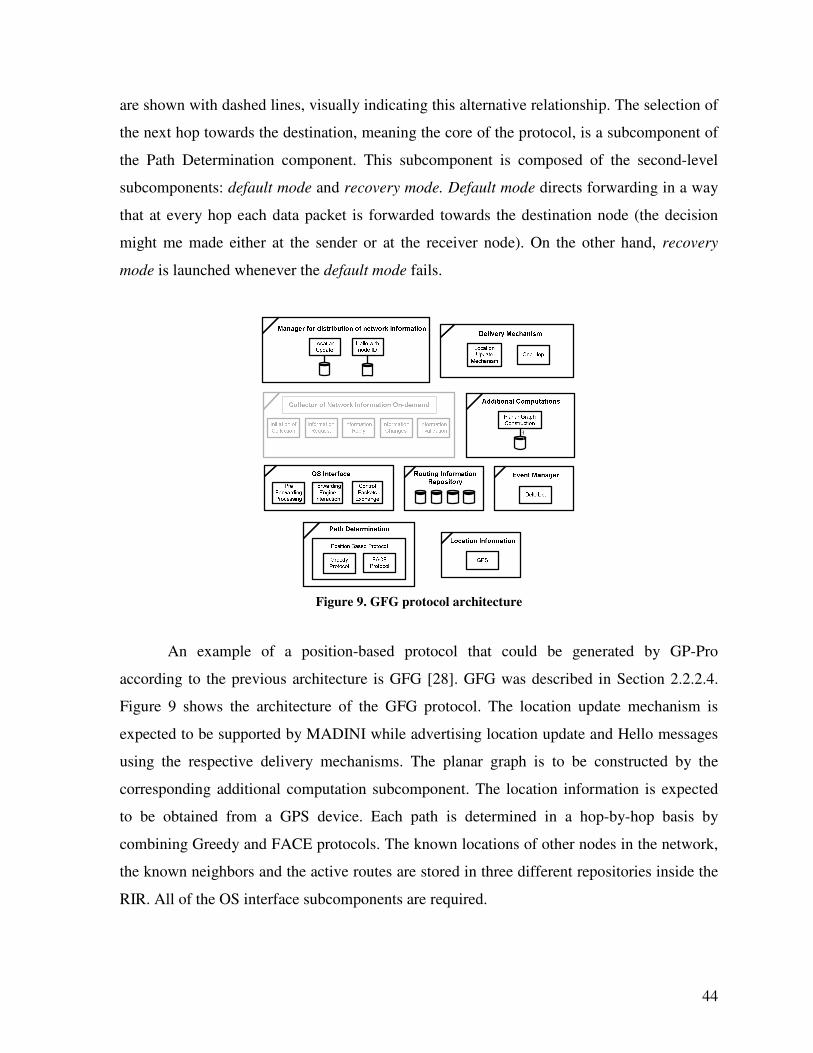
44
are shown with dashed lines, visually indicating this alternative relationship. The selection of
the next hop towards the destination, meaning the core of the protocol, is a subcomponent of
the Path Determination component. This subcomponent is composed of the second-level
subcomponents: default mode and recovery mode. Default mode directs forwarding in a way
that at every hop each data packet is forwarded towards the destination node (the decision
might me made either at the sender or at the receiver node). On the other hand, recovery
mode is launched whenever the default mode fails.
Figure 9. GFG protocol architecture
An example of a position-based protocol that could be generated by GP-Pro
according to the previous architecture is GFG [28]. GFG was described in Section 2.2.2.4.
Figure 9 shows the architecture of the GFG protocol. The location update mechanism is
expected to be supported by MADINI while advertising location update and Hello messages
using the respective delivery mechanisms. The planar graph is to be constructed by the
corresponding additional computation subcomponent. The location information is expected
to be obtained from a GPS device. Each path is determined in a hop-by-hop basis by
combining Greedy and FACE protocols. The known locations of other nodes in the network,
the known neighbors and the active routes are stored in three different repositories inside the
RIR. All of the OS interface subcomponents are required.
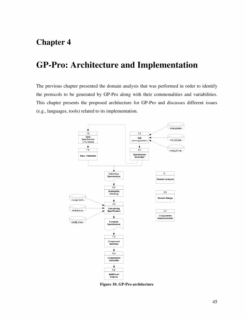
45
Chapter 4
GP-Pro: Architecture and Implementation
The previous chapter presented the domain analysis that was performed in order to identify
the protocols to be generated by GP-Pro along with their commonalities and variabilities.
This chapter presents the proposed architecture for GP-Pro and discusses different issues
(e.g., languages, tools) related to its implementation.
Figure 10. GP-Pro architecture
46
4.1 GP-Pro Architecture
One of the main reasons to design GP-Pro is to accelerate the protocol generation process
based on user requirements while achieving reasonable protocol performance [70]. Here, the
meaning of accelerating the generation process is not only related to quickly generating the
source code for the new protocol. It is also related to the mechanism to specify the required
protocol. Therefore, an easy to use but powerful mechanism is required. Such a mechanism
must be capable of processing a simple specification where only component names are listed,
but also capable of processing more complex specifications where each component is re-
configured and interconnected. Therefore, in terms of the protocol specification, GP-Pro
supports two different mechanisms to provide the user specification. The first mechanism,
which is the core and more powerful one, is a text-based user specification based on a
proprietary DSL. This is the best alternative for the more advanced user that wants to fully
specify a customized protocol. The second mechanism, which is simpler to use, is a GUI
(Graphic User Interface) that does not require any knowledge about any programming or
specification language. Only the selection of protocol features by means of lists and check
boxes is required.
Figure 10 shows the structure and processing flow of the protocol generator. Each of
the processes building the architecture of GP-Pro is described in the following sections. In
Figure 10, three processes that are not part of the processing flow are: Domain Analysis,
Domain Design and Components Implementation (shown with IDs 0.1, 0.2 and 0.3
respectively). These processes correspond to the three phases of domain engineering
described in the previous chapter. They denote the fact that domain engineering is performed
first, in order to support the protocol generator architecture. The process labeled “0.3-
Components Implementation”, which is part of the domain implementation phase emphasizes
that in order to make use of GP-Pro, the protocol components have to be implemented first.
In addition, the generator itself is also one of the outcomes of the domain implementation
phase.
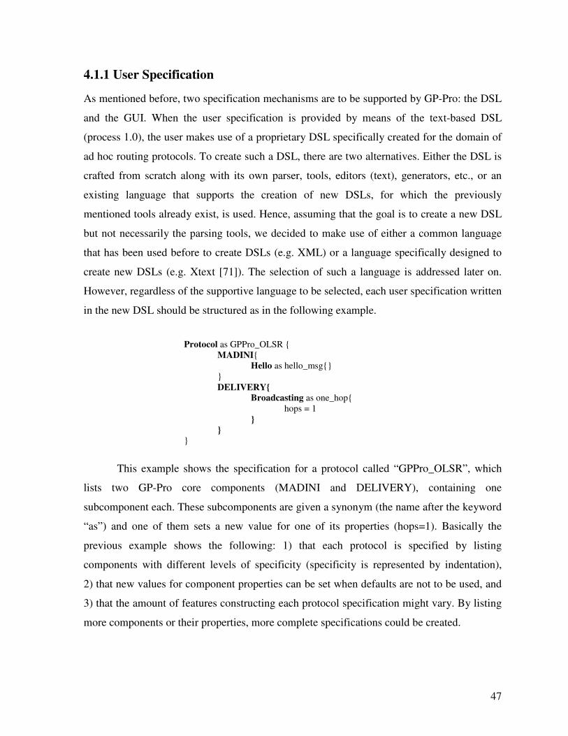
47
4.1.1 User Specification
As mentioned before, two specification mechanisms are to be supported by GP-Pro: the DSL
and the GUI. When the user specification is provided by means of the text-based DSL
(process 1.0), the user makes use of a proprietary DSL specifically created for the domain of
ad hoc routing protocols. To create such a DSL, there are two alternatives. Either the DSL is
crafted from scratch along with its own parser, tools, editors (text), generators, etc., or an
existing language that supports the creation of new DSLs, for which the previously
mentioned tools already exist, is used. Hence, assuming that the goal is to create a new DSL
but not necessarily the parsing tools, we decided to make use of either a common language
that has been used before to create DSLs (e.g. XML) or a language specifically designed to
create new DSLs (e.g. Xtext [71]). The selection of such a language is addressed later on.
However, regardless of the supportive language to be selected, each user specification written
in the new DSL should be structured as in the following example.
Protocol as GPPro_OLSR {
MADINI{
Hello as hello_msg{}
}
DELIVERY{
Broadcasting as one_hop{
hops = 1
}
}
}
This example shows the specification for a protocol called “GPPro_OLSR”, which
lists two GP-Pro core components (MADINI and DELIVERY), containing one
subcomponent each. These subcomponents are given a synonym (the name after the keyword
“as”) and one of them sets a new value for one of its properties (hops=1). Basically the
previous example shows the following: 1) that each protocol is specified by listing
components with different levels of specificity (specificity is represented by indentation),
2) that new values for component properties can be set when defaults are not to be used, and
3) that the amount of features constructing each protocol specification might vary. By listing
more components or their properties, more complete specifications could be created.
48
4.1.2 Specification Validation
Once the user has written the specification of the desired routing protocol, which is the input
for GP-Pro, it has to be validated (process 2.0). The validation process consists of checking
that the specification is well formed and that it follows the syntax constraints imposed by the
DSL.
4.1.3 Graphic User Interface
A simpler and faster alternative to provide user specifications is by means of the GUI
(process 3.0). This interface should contain list boxes, check boxes and text fields to select
the components and features of the desired protocol. The GUI should have protocol
configuration knowledge built-in. This knowledge should be extracted from the database of
components, from the routing protocol architecture and from the configuration knowledge.
The reason to provide the GUI with configuration knowledge is to prevent conflicts between
components. For example, some protocol features might forbid the selection of some other
conflicting or unnecessary features (e.g., proactive protocols do not perform route discovery).
4.1.4 Specification Generator
After the user selects from the GUI the components and features that should be part of the
protocol to be generated, this selection is passed to an additional process (process 4.0) that is
in charge of generating the specification according to the DSL specifically created for GP-
Pro. The output of this process is a valid user specification and is exactly in the same format
as the output from the specification validation process (process 2.0). Actually, an advanced
user could make use of the GUI to quickly generate a complete user specification that could
be refined later on by further configuring each protocol component. And, once the new
specification has been refined, it should be passed through the specification validation
process. As we can see, the GUI is an addition to GP-Pro to further ease the specification
process. However, it relies on the DSL. Therefore, we decided to focus our efforts on the
creation of the DSL, and to leave the development of the GUI as a desired additional feature
that will be part of our further work.
49
4.1.5 Buildability Checking
When the protocol generation reaches the buildability checking process, it is because a valid
user specification is available. However, the meaning of valid is simply that the specification
is well formed and that it conforms to the DSL syntax. Therefore, it could contain
components or features that are in conflict. In addition, it could be incomplete (notice that the
configuration knowledge built inside the GUI prevents conflicts between components). An
example of an incomplete specification that is valid is when any of the protocol components
requires some type of information that is not provided by any of the components listed in the
specification. Therefore, the buildability checking process (process 5.0) looks for conflicts
between components and for incomplete specifications. The user is informed about the
results of this process and whether the specification is complete or not.
4.1.6 Completing Specification
If the outcome from the buildability checking is that there are no conflicts between
components and that the specification is complete, then the generator proceeds to select and
assemble the components. However, in the case of conflicts and/or missing components, the
user is flagged. Depending on the nature of the problem, GP-Pro will either: a) fix the
problem by properly completing the specification (process 6.0), inform the user and proceed
with the generation, or 2) inform the user and stop the generation process. The proposal
provided by the generator to complete the specification is based on the existing components,
the protocol’s architecture and the configuration knowledge. Therefore, the output of this
process is the complete protocol specification.
4.1.7 Components Selection
The DSL specification serves as the guideline to select the components that form the new
protocol (process 7.0). The expected output from this process is the full set of components
and subcomponents that satisfy the user specification, where enough components to fulfill
the entire protocol architecture have been chosen. The relationship between elements in the
DSL specification and the chosen components is not strictly expected to be one-to-one.
50
4.1.8 Components Assembly
Once the selection of components has been made, they have to be assembled (process 8.0)
according to the protocol architecture (shown in Section 3.2) and according to the component
interconnection model introduced along with GP-Pro. This component interconnection
model, which is fully described in a later chapter, interconnects pairs of components A and B,
when component B is capable of processing a message type generated by component A. Each
message type generated by any component can be seen as an output port. Likewise, each
message type processed by any component can be seen as an input port.
4.1.9 Additional Outputs
The generation of ad hoc routing protocols in the form of source code is the main purpose of
GP-Pro. This source code is the expected outcome from the component assembly process.
However, it does not have to be the only output. Additional outputs (process 9.0) such as
documentation about the implemented architecture or data flow diagrams could be produced
as well.
4.2 GP-Pro Implementation
The proposed architecture for GP-Pro has been introduced in the previous section. Next, we
discuss the feasible alternatives to implement each process in the architecture, along with the
alternatives to implement the protocol components.
4.2.1 Components Implementation
There are several options and decisions to be made in order to implement the protocol
components. These decisions mainly depend on the technology and programming languages
that the protocols are expected to be implemented in. While several programming languages
(e.g., Java, C, C++) can be used, [41] proposes using JavaBeans, which can be
interconnected by events; and [23] proposes the development of C++ components with well
defined input/output ports that are connected by the Click language. Therefore, we have to
make the following decisions: 1) Which programming language should be used to implement
51
the components, 2) Whether to implement components from scratch or reusing components
implemented as part of some other project, and 3) How to implement each of the processes in
the architecture of GP-Pro. All of these decisions were made during the creation of GP-Pro.
The alternatives that were considered along the process are discussed next.
In terms of the implementation language, the decision to make was mainly choosing
between two of the most commonly used programming languages, Java and C. By looking at
existing frameworks [12, 13, 39] and some of the deployable implementations of ad hoc
routing protocols available [60, 72, 73], we realized that all of them are implemented in C or
C++ (languages that are also expected to achieve better performance than Java). Therefore,
those two languages seemed to be the best choice. Additionally, for evaluation purposes of
the protocols generated with GP-Pro, and in order to perform a fair comparison against their
handcrafted counterparts (those implemented without the use of any generic framework or
tool) we thought that the use of the same language would be a better choice. As a result, we
decided to use either C or C++. The final choice is addressed below.
The next decision to make was about reusing existing components or creating new
ones from scratch. We had two reasons pointing towards reusing existing components. The
first reason was that the development of new components without reusing any existing
implementation would be a very time-consuming task that could consume a considerable
amount of development time, which could be better spent focusing on the rest of the
processes in the architecture of GP-Pro. The Component Based Routing project (CBR) [45],
whose only objective is the development of ad hoc routing protocol components, is a clear
example of the effort that is required to develop new components. CBR is a four year joint
project between five universities and three corporations with more than fifteen participants.
The second reason was that the main idea behind GP-Pro is the reuse of available resources
(e.g., components) to generate different types of protocols with minimal effort. Therefore, the
reuse of existing components is a better match for the GP-Pro philosophy. The JavaBeans
proposed in [41] were discarded because of the small number of existing components, lack of
compatibility and the fact that they were not implemented in any of the chosen languages (C
or C++). Another alternative, which seemed to be a pretty obvious one, are the elements of
52
the Click router project [23]. However, by analyzing the routing protocol implementations
available for DSDV [23], DSR [42] and OLSR [43] we realized that the packet processor
nature of the Click components (the so-called elements) limits the implementation of the
entire routing protocol to one or two components; an approach that does not support the idea
of developing components of fine-granularity to achieve higher reusability. A better match
are the components developed as part of the CBR project [45] which are actually components
to build ad hoc routing protocols. However, those components have not been made available.
Then, the last feasible alternative to reuse any existing implementation is to create our own
components by breaking into “pieces” one of the existing deployable, handcrafted
implementations. Hence, we decided to look at the existing implementations with two criteria
in mind. First, the implementations should be functional, meaning that they should be in fact
deployable and should perform routing on a real network (hopefully bug-free). Second, the
implementation should be modular. From over ten implementations that we attempted to test
(we say attempted because not all of them could be actually deployed), three of them were
deployed and performed proper routing. The useful implementations were DYMOUM [60],
AODV-UU [72] and OLSRD [73], all of them implemented in C. Out of those three,
DYMOUM and AODV-UU were the implementations with a more modular approach, which
are a better match to the idea of creating components out of existing implementations.
Additionally, preference was given to reactive protocols because of the additional complexity
to deal with the OS routing table when no route to the destination is available and packets are
not to be dropped. Therefore, DYMOUM, an implementation of the DYMO protocol written
in C, which is a simplified successor of AODV and the focus of current efforts by the IETF
in terms of reactive protocols, was the chosen implementation to be reused. Next, we had to
decide on the process of creating protocol components from this implementation.
[64] presents several alternatives to create program generators and suggests the use of
templates as elements that can be combined with a specification and processed by a template
engine to produce the desired program. [74] proposes another template engine called XVCL
(XML-based Variant Configuration Language) that can introduce changes (variabilities) into
programs represented as hierarchies of templates. XVCL templates called x-frames are based
on the framing technology proposed in [75]. This approach to generate programs as a
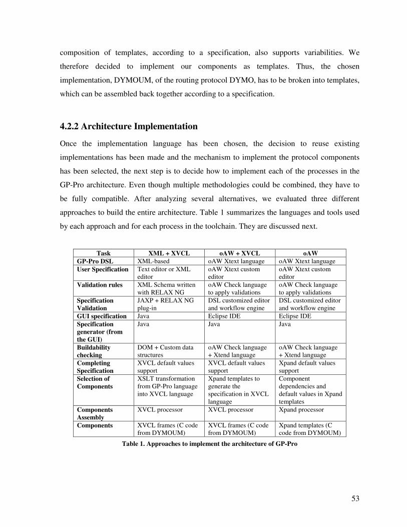
53
composition of templates, according to a specification, also supports variabilities. We
therefore decided to implement our components as templates. Thus, the chosen
implementation, DYMOUM, of the routing protocol DYMO, has to be broken into templates,
which can be assembled back together according to a specification.
4.2.2 Architecture Implementation
Once the implementation language has been chosen, the decision to reuse existing
implementations has been made and the mechanism to implement the protocol components
has been selected, the next step is to decide how to implement each of the processes in the
GP-Pro architecture. Even though multiple methodologies could be combined, they have to
be fully compatible. After analyzing several alternatives, we evaluated three different
approaches to build the entire architecture. Table 1 summarizes the languages and tools used
by each approach and for each process in the toolchain. They are discussed next.
Task XML + XVCL oAW + XVCL oAW
GP-Pro DSL XML-based oAW Xtext language oAW Xtext language
User Specification Text editor or XML
editor
oAW Xtext custom
editor
oAW Xtext custom
editor
Validation rules XML Schema written
with RELAX NG
oAW Check language
to apply validations
oAW Check language
to apply validations
Specification
Validation
JAXP + RELAX NG
plug-in
DSL customized editor
and workflow engine
DSL customized editor
and workflow engine
GUI specification Java Eclipse IDE Eclipse IDE
Specification
generator (from
the GUI)
Java Java Java
Buildability
checking
DOM + Custom data
structures
oAW Check language
+ Xtend language
oAW Check language
+ Xtend language
Completing
Specification
XVCL default values
support
XVCL default values
support
Xpand default values
support
Selection of
Components
XSLT transformation
from GP-Pro language
into XVCL language
Xpand templates to
generate the
specification in XVCL
language
Component
dependencies and
default values in Xpand
templates
Components
Assembly
XVCL processor XVCL processor Xpand processor
Components XVCL frames (C code
from DYMOUM)
XVCL frames (C code
from DYMOUM)
Xpand templates (C
code from DYMOUM)
Table 1. Approaches to implement the architecture of GP-Pro
54
4.2.2.1 XML and XVCL
The first approach consists of a combination of several programming languages and software
tools. The central features are XML (eXtensible Markup Language) and XVCL. The entire
architecture is created as follows. The DSL for GP-Pro is manually created as an XML-like
language. Therefore, existing parsers, editors, viewers and conversion tools for XML can be
used by the new DSL. GP-Pro components are represented by XML elements [64] and
configuration parameters by XML attributes. The user specification is written using any text
editor or XML editor. The validation rules for the user specification are defined by creating
the corresponding XML Schema. An XML Schema is a description of a type of XML
document, which is usually expressed by constraints on the content and structure of
documents of that type, above and beyond the basic constraints imposed by XML itself. The
list of languages developed specifically to express XML schemas is long [76]. However,
three have had greater influence on schema languages [77]. These schema languages are the
Document Type Definition (DTD) language, the World Wide Web Consortium XML
Schema language (XSD) and RELAX NG (Relax New Generation). DTD is native to the
Standard Generalized Markup Language (SGML) and XML specifications, but its
capabilities are somewhat limited compared to more modern schema languages. XML
Schema is the language supported by the World Wide Web Consortium (W3C) and it offers
advantages over DTD such as data types that can be used to constrain the character data in an
element’s content or attribute values. However, it involves some complex mechanisms, has a
long learning curve and is rather rigid [78]. On the other hand, RELAX NG [79] is a simpler
language, easier to learn, and an ISO standard, which provides XML and non-XML syntax
while providing functionalities similar to the XML Schema language plus some more.
Therefore, RELAX NG is the language used to express the XML Schema.
To actually perform the specification validation, the Java API for XML Processing
(JAXP) [80] is used along with the corresponding plug-in that supports RELAX NG. The
GUI alternative to specify the required protocol along with a supportive module to generate
the protocol specification out of the GUI is implemented by using the Java language. The
buildability checking process to look for conflicts between components or any missing
component is performed by using the Document Object Model (DOM), in order to access the

55
XML user specification document, extract the user preferences and load them into a custom
data structure that is used to identify any existing conflict. DOM is a platform-independent
and language-independent object model to represent XML related formats, which supports
navigation through the hierarchical representation of the XML document. JAXP includes the
required Java DOM API. This approach assumes that the protocol components are available
as XVCL frames containing C code. Therefore, to generate a specification document with the
selection of components (frames in this case) that can be actually used to implement the
routing protocol, a transformation from the new DSL into XVCL language has to be
performed. Such a transformation is made by a set of XSLT templates (to be created) that
support the language transformation when injected into an XSLT processor along with the
complete DSL protocol specification. The output of such a transformation, which is in the
form of one main XVCL frame, is the input for the XVCL processor, along with the available
protocol components, in order to perform the assembly of components and finally generate
the expected implementation code. The completion of the specification (if required) is
supported by the default values supported by XVCL frames when some of the configuration
parameters are not provided. This capability to support default values was one of the main
reasons to consider XVCL as the engine to generate the source code. Another frame
processor that was considered instead of XVCL was ANGIE [81]. However, it is not as
mature or easy to use as XVCL. As can be noticed, this approach to generate the processes of
the GP-Pro architecture combines many languages and tools that add complexity to the
implementation process and certainly challenge further extensibility of the protocol
generator, especially for new users. Therefore, next, we explore another two approaches,
which provide a more transparent interoperability between the chosen tools and languages.
4.2.2.2 OpenArchitectureWare and XVCL
As mentioned in the literature review, several software generation paradigms have been
recently proposed and investigated. Model-Driven Development is one of them, which shares
similar objectives with Generative Programming. OpenArchitectureWare is a MDD
framework implemented in Java that provides a language family and tools to support the
development of software generators. It is available as an open-source tool which is meant to
be used within the well-known Eclipse [82] open-source software framework. Therefore,
56
after analyzing its applicability to the implementation of GP-Pro, we decided to make use of
it, and combine it with the previously chosen XVCL. The second approach to implement the
processes of the GP-Pro architecture is therefore as follows. The DSL is created by using the
Xtext framework [71], which supports the generation of textual DSLs. Once the new DSL
has been described by using the Xtext language, the framework creates a custom editor for
the new DSL featuring syntax coloring, constrain checking (assuming that constraints have
been defined by using a complementary language, called Check) and basic code completion.
The user specification is provided by using the new custom editor for the new DSL, which
can be delivered as an Eclipse [82] plug-in. The validation rules for the user specification are
defined by using the Check language [83], which is another member of the oAW language
family. The constraints defined with Check can be applied in batch mode as well as
interactively. Therefore, the specification validation can be performed interactively inside
the custom editor or in batch by using the oAW workflow engine [84], which is a
configurable generator engine that provides an XML-based configuration language to define
a set of processes to be executed in sequence. The GUI and the corresponding module for
specification generation can be implemented using the Java language. The buildability
checking is performed with the support of additional constraints defined by using the Check
language and perhaps by using another member of the oAW languages family, the Xtend [85]
language, which enriches the capabilities of the other oAW languages. Even though the
family of oAW languages includes several members, they are based on a common expression
language and type system that simplifies their learning curve. The challenge to use them is
due to the limited amount of documentation available (a few pages for each language). This
approach makes use of the same types of components, the same process to assemble them,
and the same mechanism to complete the specification as the approach described in the
previous section. However, the selection of components is performed in a different way. In
this case, the transformation from the new DSL into XVCL is performed by a set of Xpand
[86] templates (to be created) that support the transformation when injected into the Xpand
processor along with the DSL specification. Xpand is the template language in the oAW
family, which is used to control the output (source code) generation. The output of the
transformation is in the form of one main XVCL frame as well. This second approach
simplifies the implementation by replacing the many different languages and tools from
57
multiple sources, used for the first half of processes in the GP-Pro architecture, by the oAW
family. Even though the oAW family comprises several languages, they were designed to
interoperate and to be compatible. We consider this approach more feasible than the one
described before.
4.2.2.3 OpenArchitectureWare only
The second approach simplifies the implementation process. However, if we take a closer
look we can see that the user specification experiences two transformations before becoming
the actual source code for deployment. First, the user specification in the new DSL language
is transformed into the main XVCL frame (user specification in XVCL language) by using
the Xpand templates and the Xpand processor. Then, the XVCL frame, along with the
components implemented as additional frames, are transformed into the C source code, by
using the XVCL processor. Therefore, the third approach that we propose ignores XVCL,
and only relies on the oAW family of tools and languages. In this case the protocol
components are implemented as Xpand templates instead of XVCL frames. The assembly of
components is performed by the Xpand processor, which can combine the user specification
in the new DSL language with the Xpand templates in order to produce the protocol source
code. This approach reduces the number of transformations to a single one, from the DSL to
C code directly, which reduces implementation complexity and simplifies the extensibility of
GP-Pro. Therefore, we decided to proceed with the implementation of the GP-Pro
architecture by following this third proposed approach.
4.2.3 Kernel Interaction
Routing protocols can be implemented either at the user or at the kernel-level of an operating
system. Implementations at the kernel-level achieve better performance; however, they
consume more system resources (e.g., system memory) even if they are not in use because
they are always part of the system kernel. Also, any upgrade or modification to the protocol
implementation requires the regeneration of the system kernel, which challenges
maintenance. On the other hand, user-level implementations improve maintainability and
modularity. However, they experience lower performance because any message received or
58
sent has to traverse the entire protocol stack at the kernel-level and reach the user-level.
Nevertheless, some other possibilities in between these two extremes exist. One of them is
the use of loadable kernel modules (LKM), which are object files that contain code to extend
the running kernel. The advantages of using LKMs is that they can be loaded and unloaded
as required, freeing memory when not used and no modifications to the running kernel are
required. This implementation approach is followed by [72] and [60]. Another approach
oriented to achieve platform-independency presented in [58] implements the routing protocol
at user-level and uses raw sockets (socket type that does not strip packet headers) to transfer
each packet received to the user-space. The drawbacks of the later approach are that it
requires kernel modifications to be performed and also that the continuous exchange of
packets between user and kernel-level degrades performance. Therefore, in order to avoid
performance degradation and kernel modifications, we decided to make use of LKMs.
In terms of the types of routing protocols to be generated by GP-Pro, reactive and
position-based protocols are the ones that require some additional processing done at the
kernel-level. This situation arises when no routing path is available for a packet that is to be
sent through the network. In the case of reactive protocols, it usually means that a route
discovery process has to be started. In the case of position-based protocols, it happens
because no routing table is maintained and routing decisions are made on a hop-by-hop basis.
To the operating system, the unavailability of a routing path translates into dropping the
packet. Therefore, to avoid the scenario of packets being dropped, we decided to make use of
the Netfilter framework [38] (in combination with LKMs). Netfilter is a framework that
provides a set of hooks within the kernel to intercept and manipulate network packets. Such
packets can be altered, dropped or re-routed by code segments that have registered
themselves on each Netfilter hook. In the case that packets have to be processed in user-
space, Netfilter allows queuing packets at the kernel-level while information about the packet
is sent to user-space and until the user-space application returns a verdict indicating the
action to take for those packets.
59
4.2.4 What GP-Pro Does Not Do
To further clarify the objectives and capabilities of GP-Pro, we want to comment on what
GP-Pro does NOT do.
• Even though there is configuration knowledge built-in inside GP-Pro, it does not
attempt to generate routing protocols based on subjective user requirements such as
“Generate an energy efficient protocol”. GP-Pro generates protocols by assembling
existing components that are chosen by the user by means of a protocol specification.
Additionally, GP-Pro completes user specifications by providing default component
parameter values and by adding missing interconnections between components that
were not defined by the user. The capability to understand subjective requirements
certainly is an attractive capability that could be incorporated later on by enriching
the configuration knowledge.
• GP-Pro generates routing protocols based on the chosen components expressed by the
user specification. Therefore, the expected output is indeed a routing protocol.
However, no formal verification of routing capabilities or any other property is
performed. Protocol verification is a complex research field on its own.
60
Chapter 5
Component Interconnection Model
GP-Pro is a protocol generator of ad hoc routing protocols. The routing protocols are
generated by assembling components of diverse functionalities, which all together perform
routing tasks. Assuming that such compatible components can be implemented, common
interfaces to properly interconnect them along with interaction mechanisms have to be
designed. This chapter describes the generic architecture of the GP-Pro components, their
interfaces and the interconnection model that allows for component interaction.
In GP-Pro, components are treated and implemented as black boxes that exchange
messages through communication ports. Communication ports pass messages in only one
single direction, meaning that no messages are expected to be received by an output port or
sent out by an input port. Therefore, any pair of components can communicate by
interconnecting the output port of the first one to the input port of the second one, and by
exchanging a message type that is known to both of them. In addition to this interaction
mechanism that provides direct communication between components, there are another two
mechanisms that provide indirect communication. The first of them is throughout the
scheduling component called Event Manager. Routing components might require scheduling
predefined tasks for future execution. They do so by sending a message to register a task with
the Event Manager. Each task is associated with a timer. Once the timer expires, a message is
delivered from the Event Manager to the component expected to execute the task. The
second mechanism is throughout the RIR (Routing Information Repository). Each
component carries out one or more tasks during execution. As a result it might need to make
use of repositories for information storage. Therefore, components communicate with the
RIR component to create and to maintain one or more repositories. All of the repositories
inside the RIR component can be accessed by any of the protocol components. Hence,
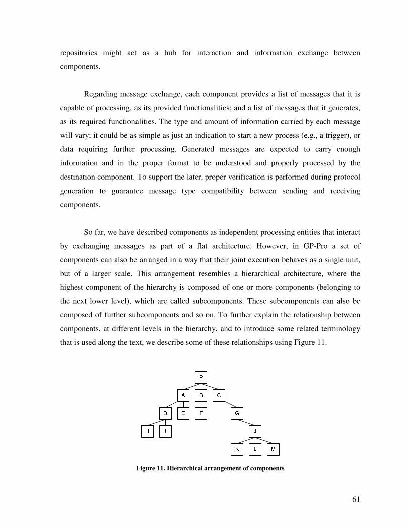
61
repositories might act as a hub for interaction and information exchange between
components.
Regarding message exchange, each component provides a list of messages that it is
capable of processing, as its provided functionalities; and a list of messages that it generates,
as its required functionalities. The type and amount of information carried by each message
will vary; it could be as simple as just an indication to start a new process (e.g., a trigger), or
data requiring further processing. Generated messages are expected to carry enough
information and in the proper format to be understood and properly processed by the
destination component. To support the later, proper verification is performed during protocol
generation to guarantee message type compatibility between sending and receiving
components.
So far, we have described components as independent processing entities that interact
by exchanging messages as part of a flat architecture. However, in GP-Pro a set of
components can also be arranged in a way that their joint execution behaves as a single unit,
but of a larger scale. This arrangement resembles a hierarchical architecture, where the
highest component of the hierarchy is composed of one or more components (belonging to
the next lower level), which are called subcomponents. These subcomponents can also be
composed of further subcomponents and so on. To further explain the relationship between
components, at different levels in the hierarchy, and to introduce some related terminology
that is used along the text, we describe some of these relationships using Figure 11.
Figure 11. Hierarchical arrangement of components
62
Figure 11 shows a component P (the highest in the hierarchy), which is composed of
13 subcomponents arranged in 4 subcomponent levels. The first level is composed of A, B,
and C. The second level is composed of D, E, F and G. The third level is composed of H, I
and J. Finally, the fourth level is composed of K, L and M. Any component Z, containing
subcomponents, is considered the super-component of all of its subcomponents, located at all
subcomponent levels. Any component Z is considered a subcomponent of all of those
components that are higher in the hierarchy than Z itself, which are also super-components of
Z. An immediate subcomponent of Z is any of its subcomponents at the next lower
hierarchical level. The immediate super-component of Z is its super-component at the next
higher hierarchical level. Components composed of one or more subcomponents are called
composite components. Components without any subcomponent are called basic components.
According to these definitions, all of the following sentences are true with respect to Figure
11:
• All of the components, except for P, are subcomponents of component P
• M is a subcomponent of J, G, C and P.
• C is the immediate subcomponent of P that contains M.
• J is the immediate super-component of M.
• J, G, C and P are super-components for M.
• M is a 4th
level subcomponent of P, 3rd
of C, 2nd
of G and 1st of J.
• P, A, B, C, D, G and J are composite components.
• H, I, E, F, K, L and M are basic components.
5.1 Basic Components
After the previous introduction to the proposed interconnection model, and the hierarchical
relationship between components, next, we describe in detail the architecture of a generic
basic component. Figure 12 shows the structure of a basic component. It is composed of an
internal component process that executes the component’s task, a Message Distribution
Controller (MDC), one input port (the ‘T’ connector on the left side with the arrow pointing
away) and one output port (the ‘T’ connector on the right side with the arrow pointing
towards). Any message generated by the internal component process is delivered to the MDC
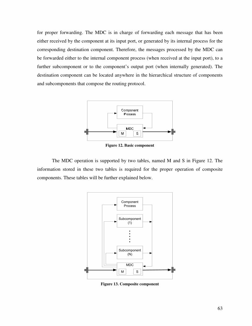
63
for proper forwarding. The MDC is in charge of forwarding each message that has been
either received by the component at its input port, or generated by its internal process for the
corresponding destination component. Therefore, the messages processed by the MDC can
be forwarded either to the internal component process (when received at the input port), to a
further subcomponent or to the component’s output port (when internally generated). The
destination component can be located anywhere in the hierarchical structure of components
and subcomponents that compose the routing protocol.
Figure 12. Basic component
The MDC operation is supported by two tables, named M and S in Figure 12. The
information stored in these two tables is required for the proper operation of composite
components. These tables will be further explained below.
Component
Process
MDC
M S
Subcomponent
(N)
Subcomponent
(1)
Figure 13. Composite component
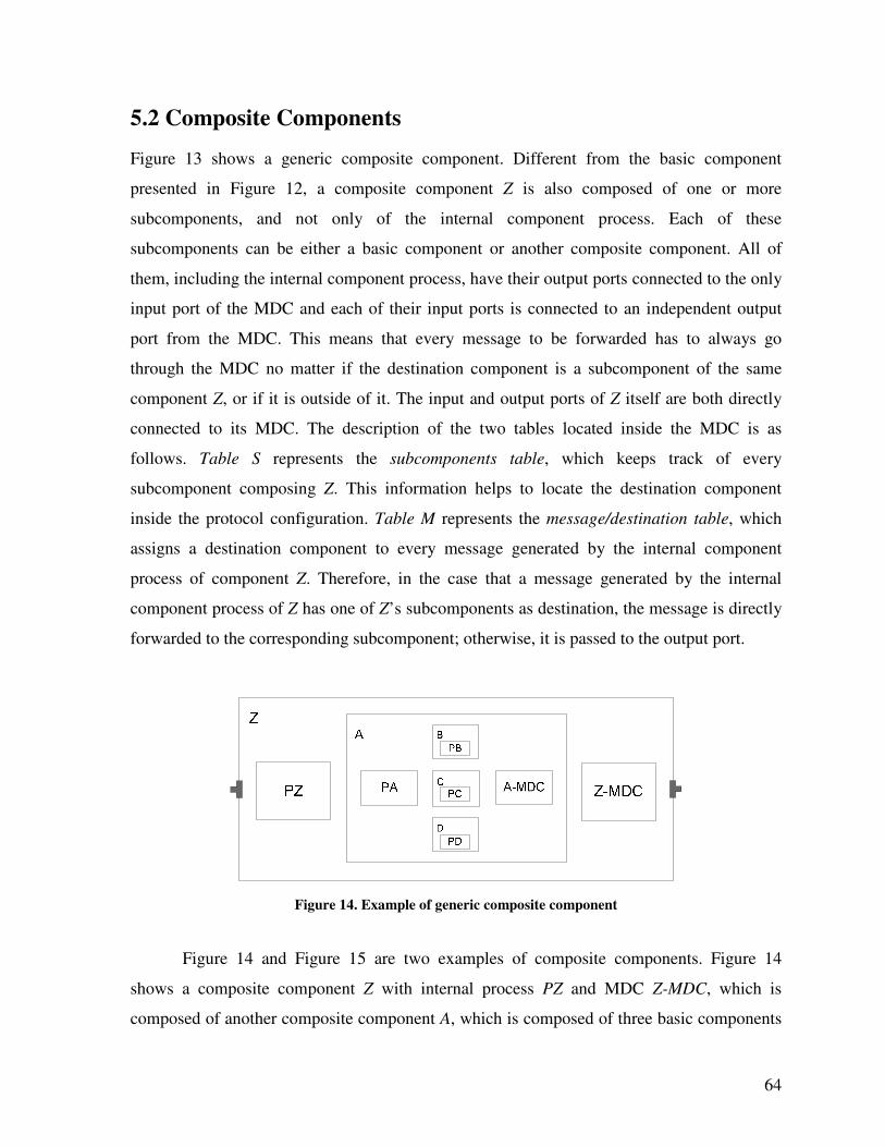
64
5.2 Composite Components
Figure 13 shows a generic composite component. Different from the basic component
presented in Figure 12, a composite component Z is also composed of one or more
subcomponents, and not only of the internal component process. Each of these
subcomponents can be either a basic component or another composite component. All of
them, including the internal component process, have their output ports connected to the only
input port of the MDC and each of their input ports is connected to an independent output
port from the MDC. This means that every message to be forwarded has to always go
through the MDC no matter if the destination component is a subcomponent of the same
component Z, or if it is outside of it. The input and output ports of Z itself are both directly
connected to its MDC. The description of the two tables located inside the MDC is as
follows. Table S represents the subcomponents table, which keeps track of every
subcomponent composing Z. This information helps to locate the destination component
inside the protocol configuration. Table M represents the message/destination table, which
assigns a destination component to every message generated by the internal component
process of component Z. Therefore, in the case that a message generated by the internal
component process of Z has one of Z’s subcomponents as destination, the message is directly
forwarded to the corresponding subcomponent; otherwise, it is passed to the output port.
Figure 14. Example of generic composite component
Figure 14 and Figure 15 are two examples of composite components. Figure 14
shows a composite component Z with internal process PZ and MDC Z-MDC, which is
composed of another composite component A, which is composed of three basic components
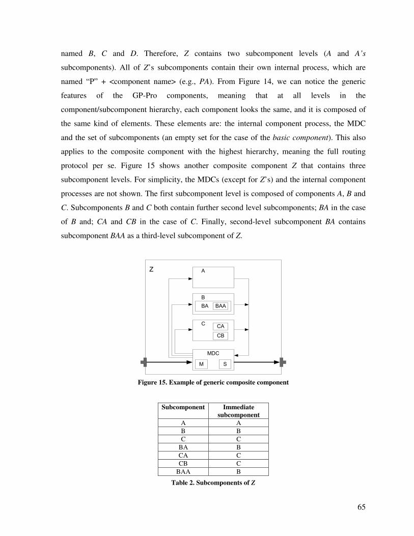
65
named B, C and D. Therefore, Z contains two subcomponent levels (A and A’s
subcomponents). All of Z’s subcomponents contain their own internal process, which are
named “P” + <component name> (e.g., PA). From Figure 14, we can notice the generic
features of the GP-Pro components, meaning that at all levels in the
component/subcomponent hierarchy, each component looks the same, and it is composed of
the same kind of elements. These elements are: the internal component process, the MDC
and the set of subcomponents (an empty set for the case of the basic component). This also
applies to the composite component with the highest hierarchy, meaning the full routing
protocol per se. Figure 15 shows another composite component Z that contains three
subcomponent levels. For simplicity, the MDCs (except for Z’s) and the internal component
processes are not shown. The first subcomponent level is composed of components A, B and
C. Subcomponents B and C both contain further second level subcomponents; BA in the case
of B and; CA and CB in the case of C. Finally, second-level subcomponent BA contains
subcomponent BAA as a third-level subcomponent of Z.
Z
C
MDC
M S
A
B
BA BAA
CA
CB
Figure 15. Example of generic composite component
Subcomponent Immediate
subcomponent
A A
B B
C C
BA B
CA C
CB C
BAA B
Table 2. Subcomponents of Z
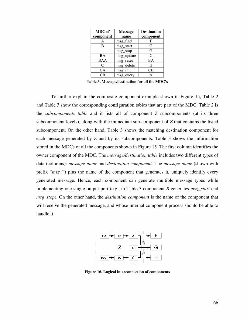
66
MDC of
component
Message
name
Destination
component
A msg_find F
msg_start G B
msg_stop G
BA msg_update C
BAA msg_reset BA
C msg_delete H
CA msg_init CB
CB msg_query A
Table 3. Message/destination for all the MDC’s
To further explain the composite component example shown in Figure 15, Table 2
and Table 3 show the corresponding configuration tables that are part of the MDC. Table 2 is
the subcomponents table and it lists all of component Z subcomponents (at its three
subcomponent levels), along with the immediate sub-component of Z that contains the listed
subcomponent. On the other hand, Table 3 shows the matching destination component for
each message generated by Z and by its subcomponents. Table 3 shows the information
stored in the MDCs of all the components shown in Figure 15. The first column identifies the
owner component of the MDC. The message/destination table includes two different types of
data (columns): message name and destination component. The message name (shown with
prefix “msg_”) plus the name of the component that generates it, uniquely identify every
generated message. Hence, each component can generate multiple message types while
implementing one single output port (e.g., in Table 3 component B generates msg_start and
msg_stop). On the other hand, the destination component is the name of the component that
will receive the generated message, and whose internal component process should be able to
handle it.
Figure 16. Logical interconnection of components
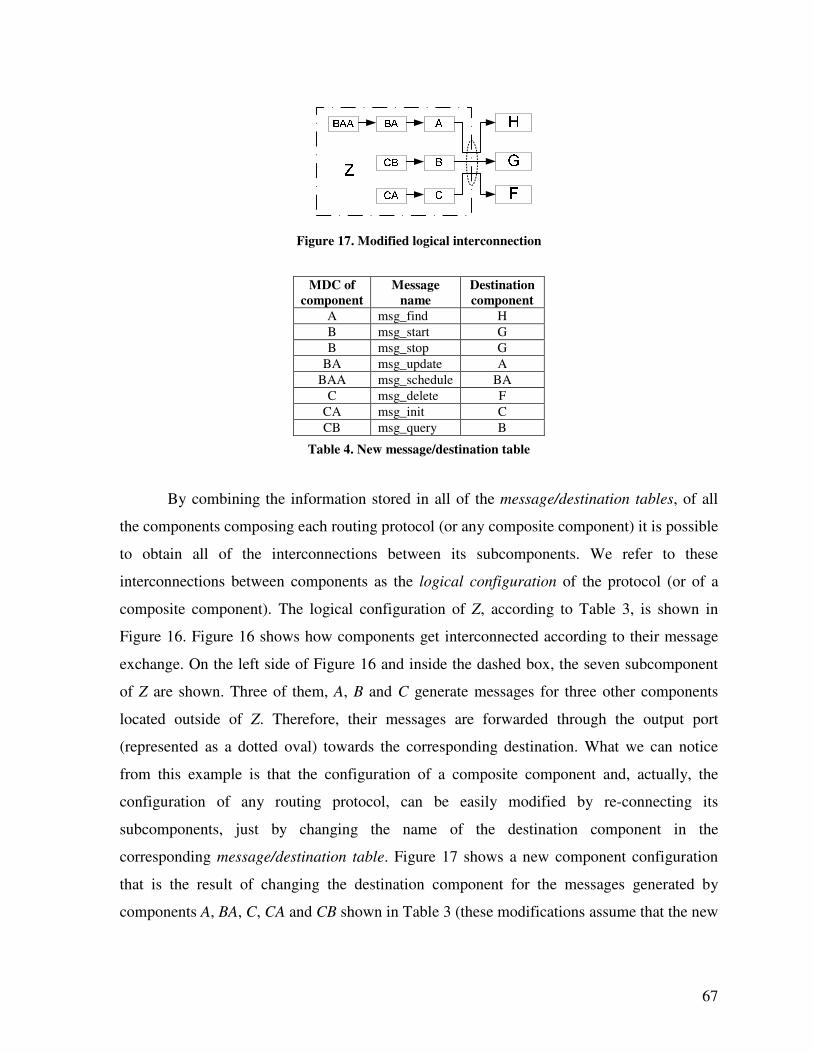
67
Figure 17. Modified logical interconnection
MDC of
component
Message
name
Destination
component
A msg_find H
B msg_start G
B msg_stop G
BA msg_update A
BAA msg_schedule BA
C msg_delete F
CA msg_init C
CB msg_query B
Table 4. New message/destination table
By combining the information stored in all of the message/destination tables, of all
the components composing each routing protocol (or any composite component) it is possible
to obtain all of the interconnections between its subcomponents. We refer to these
interconnections between components as the logical configuration of the protocol (or of a
composite component). The logical configuration of Z, according to Table 3, is shown in
Figure 16. Figure 16 shows how components get interconnected according to their message
exchange. On the left side of Figure 16 and inside the dashed box, the seven subcomponent
of Z are shown. Three of them, A, B and C generate messages for three other components
located outside of Z. Therefore, their messages are forwarded through the output port
(represented as a dotted oval) towards the corresponding destination. What we can notice
from this example is that the configuration of a composite component and, actually, the
configuration of any routing protocol, can be easily modified by re-connecting its
subcomponents, just by changing the name of the destination component in the
corresponding message/destination table. Figure 17 shows a new component configuration
that is the result of changing the destination component for the messages generated by
components A, BA, C, CA and CB shown in Table 3 (these modifications assume that the new
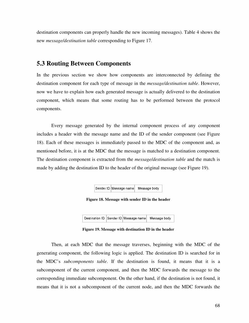
68
destination components can properly handle the new incoming messages). Table 4 shows the
new message/destination table corresponding to Figure 17.
5.3 Routing Between Components
In the previous section we show how components are interconnected by defining the
destination component for each type of message in the message/destination table. However,
now we have to explain how each generated message is actually delivered to the destination
component, which means that some routing has to be performed between the protocol
components.
Every message generated by the internal component process of any component
includes a header with the message name and the ID of the sender component (see Figure
18). Each of these messages is immediately passed to the MDC of the component and, as
mentioned before, it is at the MDC that the message is matched to a destination component.
The destination component is extracted from the message/destination table and the match is
made by adding the destination ID to the header of the original message (see Figure 19).
Figure 18. Message with sender ID in the header
Figure 19. Message with destination ID in the header
Then, at each MDC that the message traverses, beginning with the MDC of the
generating component, the following logic is applied. The destination ID is searched for in
the MDC’s subcomponents table. If the destination is found, it means that it is a
subcomponent of the current component, and then the MDC forwards the message to the
corresponding immediate subcomponent. On the other hand, if the destination is not found, it
means that it is not a subcomponent of the current node, and then the MDC forwards the
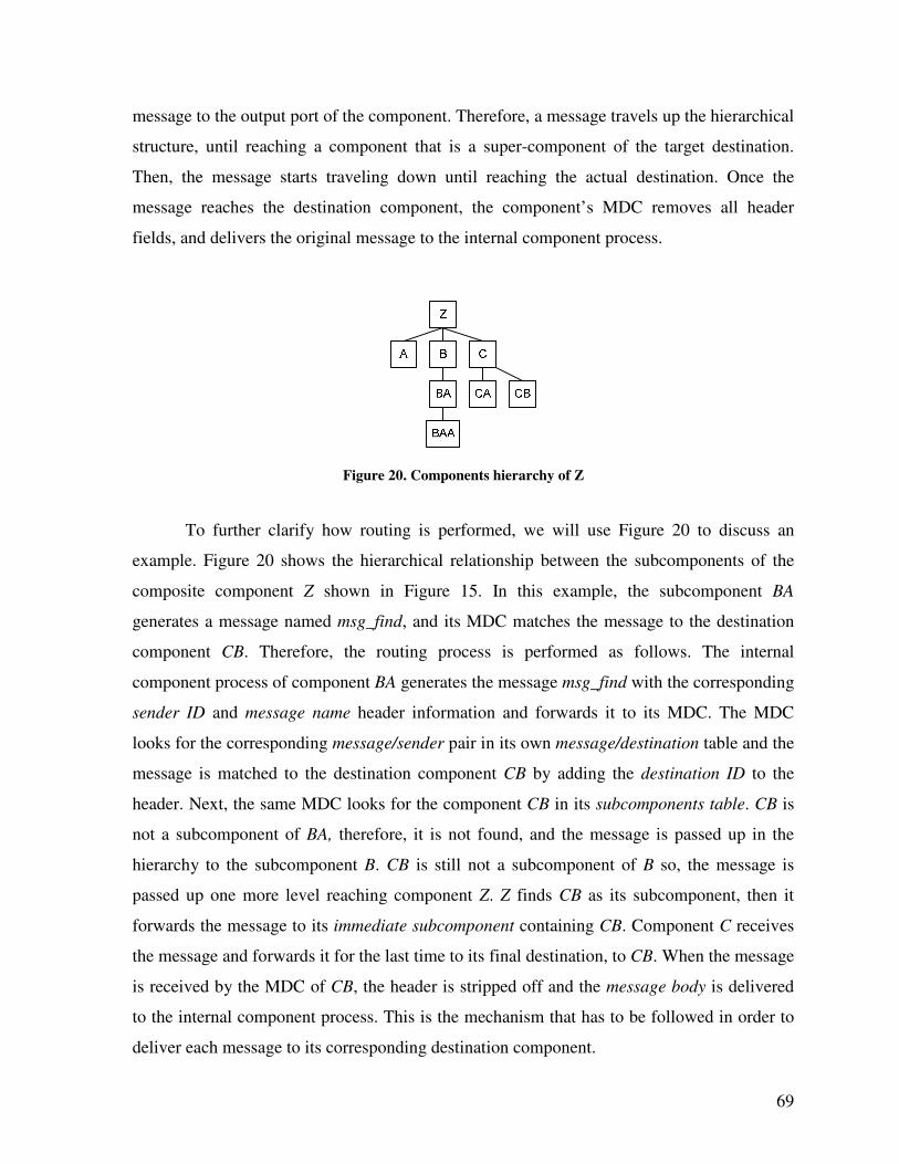
69
message to the output port of the component. Therefore, a message travels up the hierarchical
structure, until reaching a component that is a super-component of the target destination.
Then, the message starts traveling down until reaching the actual destination. Once the
message reaches the destination component, the component’s MDC removes all header
fields, and delivers the original message to the internal component process.
Figure 20. Components hierarchy of Z
To further clarify how routing is performed, we will use Figure 20 to discuss an
example. Figure 20 shows the hierarchical relationship between the subcomponents of the
composite component Z shown in Figure 15. In this example, the subcomponent BA
generates a message named msg_find, and its MDC matches the message to the destination
component CB. Therefore, the routing process is performed as follows. The internal
component process of component BA generates the message msg_find with the corresponding
sender ID and message name header information and forwards it to its MDC. The MDC
looks for the corresponding message/sender pair in its own message/destination table and the
message is matched to the destination component CB by adding the destination ID to the
header. Next, the same MDC looks for the component CB in its subcomponents table. CB is
not a subcomponent of BA, therefore, it is not found, and the message is passed up in the
hierarchy to the subcomponent B. CB is still not a subcomponent of B so, the message is
passed up one more level reaching component Z. Z finds CB as its subcomponent, then it
forwards the message to its immediate subcomponent containing CB. Component C receives
the message and forwards it for the last time to its final destination, to CB. When the message
is received by the MDC of CB, the header is stripped off and the message body is delivered
to the internal component process. This is the mechanism that has to be followed in order to
deliver each message to its corresponding destination component.
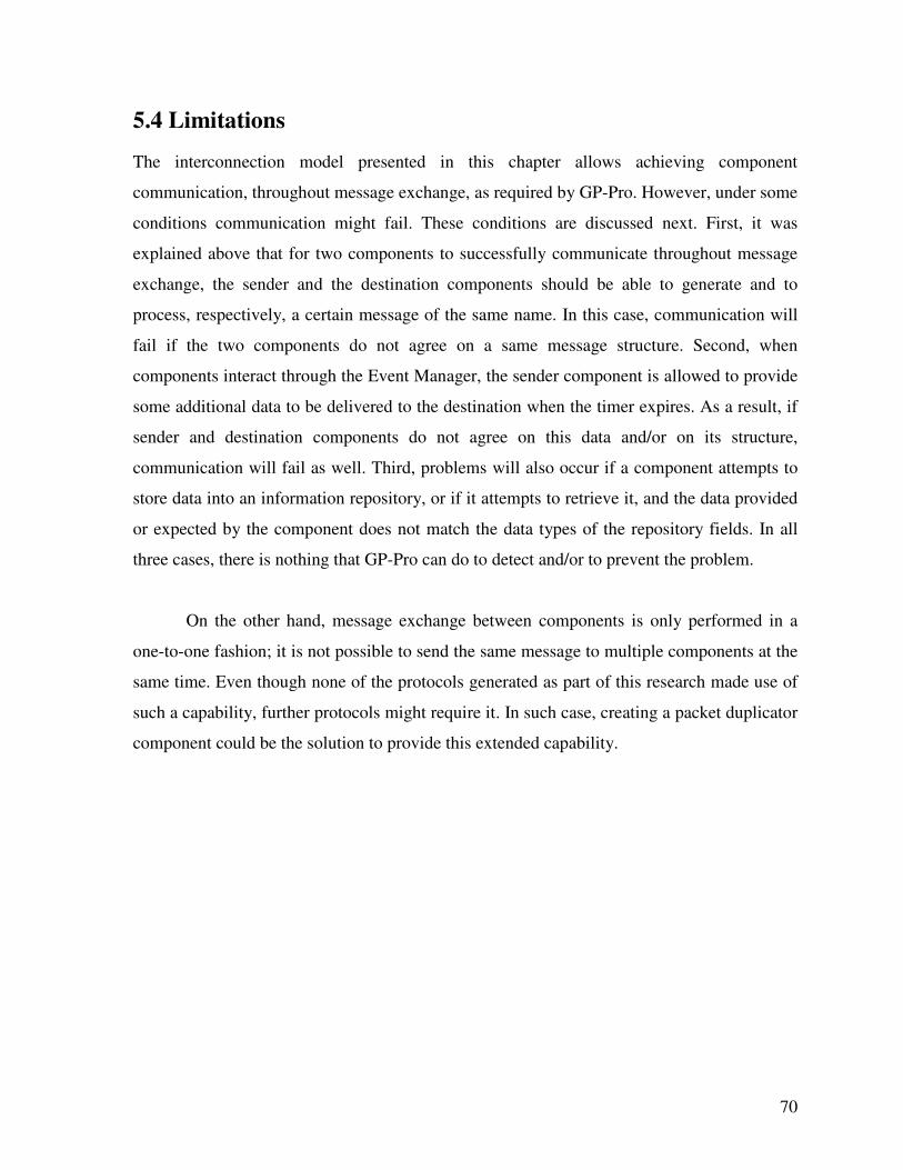
70
5.4 Limitations
The interconnection model presented in this chapter allows achieving component
communication, throughout message exchange, as required by GP-Pro. However, under some
conditions communication might fail. These conditions are discussed next. First, it was
explained above that for two components to successfully communicate throughout message
exchange, the sender and the destination components should be able to generate and to
process, respectively, a certain message of the same name. In this case, communication will
fail if the two components do not agree on a same message structure. Second, when
components interact through the Event Manager, the sender component is allowed to provide
some additional data to be delivered to the destination when the timer expires. As a result, if
sender and destination components do not agree on this data and/or on its structure,
communication will fail as well. Third, problems will also occur if a component attempts to
store data into an information repository, or if it attempts to retrieve it, and the data provided
or expected by the component does not match the data types of the repository fields. In all
three cases, there is nothing that GP-Pro can do to detect and/or to prevent the problem.
On the other hand, message exchange between components is only performed in a
one-to-one fashion; it is not possible to send the same message to multiple components at the
same time. Even though none of the protocols generated as part of this research made use of
such a capability, further protocols might require it. In such case, creating a packet duplicator
component could be the solution to provide this extended capability.
71
Chapter 6
GP-PRO: The Software Tool
Chapter 4 presented the proposed architecture for GP-Pro and discussed feasible
implementation approaches while making implementation decisions, including the method to
create the protocol components. Chapter 5 presented the interconnection model that allows
those components to be put together and to communicate by exchanging messages. Now, we
put in practice all those previous decisions along with the interconnection model to actually
generate deployable routing protocols by using our software tool: GP-Pro. Therefore, in this
chapter we present the DSL specifically created for the domain of ad hoc routing protocols,
which is meant to be used with GP-Pro; we introduce the way to implement routing
components in the form of Xpand [86] templates; and we show how to make use of the new
DSL in order to write real protocol specifications. As mentioned before, the entire
development was performed by using the integrated development environment Eclipse [82].
6.1 Specification Language
The new DSL was created by using the Xtext [71] framework. The DSL provides enough
rules for the user to write protocol specifications capable of requesting the generation of
reactive, proactive and position-based routing protocols.
Inside the Xtext framework resides the Xtext grammar language. The Xtext language
is used to describe the concrete syntax and the abstract syntax, or metamodel, of the new
DSL. A metamodel is a precise definition of the constructs and rules needed to create
semantic models. Therefore, the new DSL was created with Xtext by defining grammar
language abstractions called Rules. Two different types of rules that exist in Xtext were used
in our DSL. These rules are called Simple rule and Abstract rule. In the case of a Simple rule,
its name becomes the name of a concrete meta-type. Inside the rule, tokens are specified and
72
the values are assigned to features of the actual meta-type. On the other hand, the Abstract
rules are used to let a feature contain elements of different types. In order to show examples
of both kinds of rules a brief excerpt of the new DSL is described next. The entire DSL is
listed in Appendix A.
Protocol :
"Protocol" (" as " synonym=ID)? "{"
(properties+=Property)*
(subcomponents+=Main_Component)*
(interconnections+=Interconn)*
"}";
Main_Component : MADINI | DELIVERY | CONI | ADD_COMPS | OS_IFACE | RIR | EV_MGR |
PATH_DET | LOC_INFO;
The previous piece of the DSL describes a Simple rule called Protocol (which is also
the name of the metatype corresponding to this rule). Indentation is used to show hierarchical
relationships between rules, which represent components, and bold face type is used to
identify new rules. The rule is described after the colon and is made up of tokens. The first
token ("Protocol") is a KeywordToken, which says that a specification of a protocol starts with
the keyword “Protocol”. The protocol’s feature synonym follows. The question mark after
the parenthesis means that this feature is optional. When this feature is listed in the
specification, it has to be preceded by the KeywordToken “ as ”. The possible values for
this feature correspond to the IdentifierToken ID. The ID token defined by Xtext can be
formed by any letter, digit or the underscore character. Then, enclosed in curly brackets (“{”
and “}”), the protocol properties indicated by ((properties+=Property)*, the subcomponents
indicated by (subcomponents+=Main_Component))* and the interconnections indicated by
(interconnections+=Interconn)* should be declared. Because the structure of these three
tokens (i.e. component features) is similar to each other, we will only further explain the
subcomponents feature. The “*” means that any number of subcomponents can be declared,
even none. This time the token points to another rule (called Main_Component) and each
subcomponent is added (defined by the += operator) to the protocol’s reference called
subcomponents. The Main_Component rule is an Abstract rule that contains elements of the
types: MADINI, DELIVERY, CONI, ADD_COMPS, OS_IFACE, RIR, EV_MGR, PATH_DET
and LOC_INFO (which are the core components of GP-Pro). Each of these types are rules
73
themselves. The description of every single rule that is part of the DSL can be found in
Appendix A. All of them are either Simple or Abstract rules. Therefore, the previously
explained logic can be used to understand them all.
In the previous excerpt of the DSL we can see that the Protocol rule (or metatype),
which is the component with the highest hierarchy, might have a synonym (i.e. optional
feature), and it might be constructed by an unlimited number of properties, subcomponents
and interconnections. These features are generic and common to every other component in
the architecture. Therefore, every component (see Appendix A) allows for the same feature
specification making this component structure truly generic. In the previous excerpt we can
also see that the subcomponents of Protocol all have to be of the type Main_component,
which is a set of nine other types, each one representing one of the nine core components of
GP-Pro. The next DSL excerpt shows the rule definition of one of those other types, the
DELIVERY metatype.
DELIVERY :
"DELIVERY" (" as " synonym=ID)? "{"
(properties+=Property)*
(subcomponents+=Del_mech)+
(interconnections+=Interconn)*
"}";
Del_mech :
Del_mech_types | (" as " synonym=ID)? "{"
(properties+=Property)*
(subcomponents+=Generic_component)*
(interconnections+=Interconn)*
"}";
Generic_component :
Generic_component_types | (" as " synonym=ID)? "{"
(properties+=Property)*
(subcomponents+=Generic_component)*
(interconnections+=Interconn)*
"}" ;
In this second excerpt we can see that the same feature structure previously explained
is shared by all components. The difference between the DELIVERY metatype and Protocol
is the type of its subcomponents. In this case they have to be of the type Del_mech and the
metatype Del_mech has to have subcomponents of the type Generic_component. Finally, the
Generic_component metatype is built by subcomponents of its own type, which translates
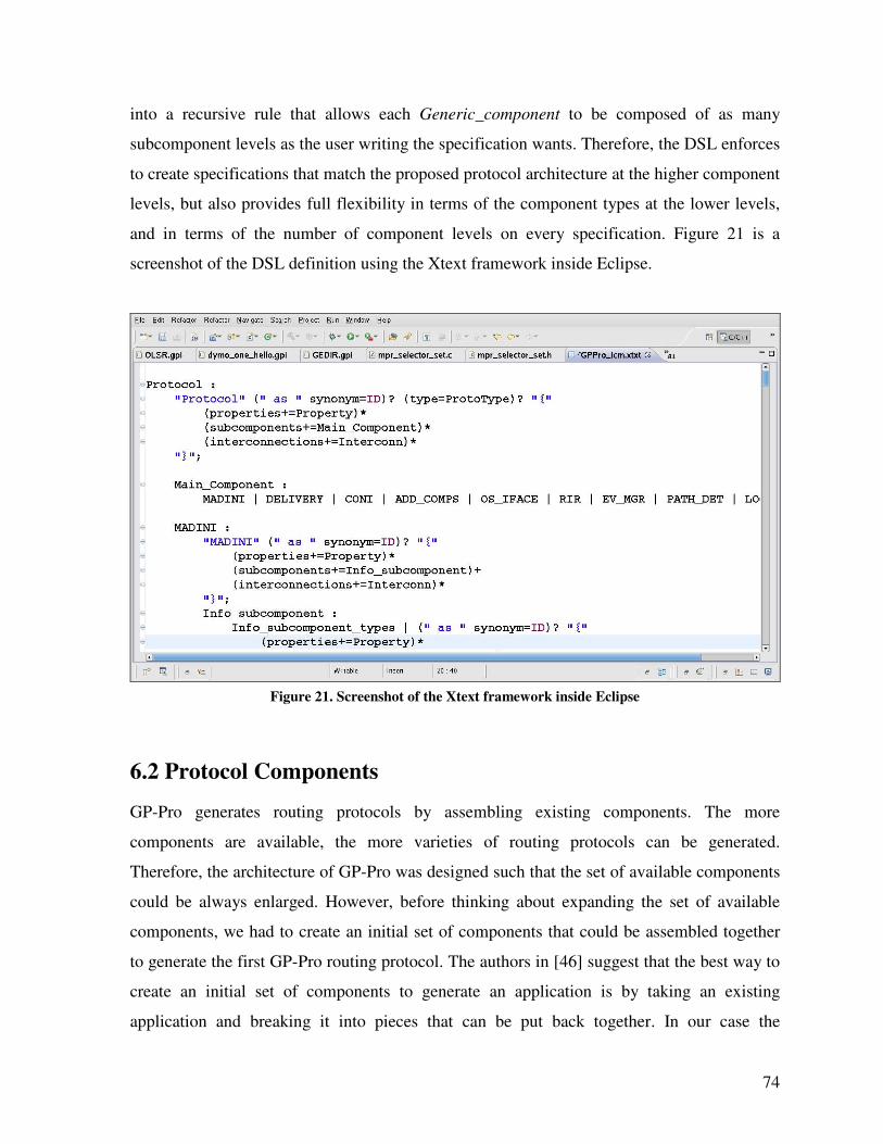
74
into a recursive rule that allows each Generic_component to be composed of as many
subcomponent levels as the user writing the specification wants. Therefore, the DSL enforces
to create specifications that match the proposed protocol architecture at the higher component
levels, but also provides full flexibility in terms of the component types at the lower levels,
and in terms of the number of component levels on every specification. Figure 21 is a
screenshot of the DSL definition using the Xtext framework inside Eclipse.
Figure 21. Screenshot of the Xtext framework inside Eclipse
6.2 Protocol Components
GP-Pro generates routing protocols by assembling existing components. The more
components are available, the more varieties of routing protocols can be generated.
Therefore, the architecture of GP-Pro was designed such that the set of available components
could be always enlarged. However, before thinking about expanding the set of available
components, we had to create an initial set of components that could be assembled together
to generate the first GP-Pro routing protocol. The authors in [46] suggest that the best way to
create an initial set of components to generate an application is by taking an existing
application and breaking it into pieces that can be put back together. In our case the
75
application is a routing protocol and those pieces should match the component architecture
previously introduced. Therefore, in order to create the initial set of protocol components, the
DYMOUM [60] implementation was used and its source code was reorganized in Xpand
templates matching the GP-Pro domain architecture. The source code reorganization was
performed by carefully analyzing the role and functionality of each data structure, each
constant definition, each macro definition and each function in the DYMOUM code in order
to find its best fit inside the GP-Pro architecture. The entire list of existing component-
templates along with a brief description is shown in Appendix B.
When a new protocol is generated, the source code is organized in one source file (.c
file) and one header file (.h file) for the user-level plus another two similar files for the
kernel-level. The kernel-level code (when required) corresponds to the pre-forwarding
processing subcomponent of the Operating System Interface core component (only used by
reactive and position-based protocols). Each source file (.c file) contains the code of all the
components that were required to generate the protocol at the corresponding level. Likewise,
the header files (.h files) contain the corresponding header declarations of each component
building the new protocol. Therefore, each time a new component is created in the form of an
Xpand template, the template should provide the code to be included in the source code file
and the code to be included in the header file. The following example shows the main
structure of an Xpand template that implements a protocol component.
«DEFINE info_subcomponent_template(String exp_type) FOR HELLO-»
«IF exp_type == "INFO"»
....<properties and messages>
«ENDIF»
«IF exp_type == "HEADERS"»
....<header code>
«ENDIF»
«IF exp_type == "BODY"»
....<source code>
«ENDIF»
«ENDDEFINE»
This example shows that each Xpand template has a name, is created for a certain
DSL metatype and is enclosed between the tags «DEFINE» and «ENDDEFINE». Inside the
76
«DEFINE» tag, the template name has to be provided along with the name of the metatype that
the template is created for. In this example, the template is named
info_subcomponent_template. The template receives the String type variable exp_type as a
parameter and it is created for the HELLO metatype. The minus character (“-”), shown after
the metatype name and before the closing bracket (“»”), is used in the Xpand language to
omit the output of superfluous white spaces.
The content of each template is divided into three main sections: INFO, HEADERS
and BODY. Each of them is delimited by IF-ENDIF blocks and is used at different stages
during the generation process. At generation time, the section of the template (one of the
previous three) that is utilized to generate the new protocol depends on the value of the
exp_type (expansion type) variable, which is controlled by the Main GP-Pro template (listed
in Appendix B). The first section (“INFO”) provides configuration information about the
component. This information is the list of configurable properties and the list of messages
that the component processes and generates. The next example is an actual INFO section of a
component template that shows how to create those listings.
«IF exp_type=="INFO"-»
«Property("msg_ival", "int", "3")»
«ProcMsg("ctl_msg_request")»
«ProcMsg("timer_timeout")»
«GenMsg("register_timer")»
«ENDIF»
The example lists one component property, two processed messages and one
generated message. Each of them is listed in an individual line of code. And, each of those
lines of code begins with the opening symbol “«” and ends with the closing symbol “»”. The
syntax to list a property is: Property(“<prop_name>”, “<prop_type>”, “<prop_value>”)
where <prop_name> indicates the name of the property; <prop_type> the data type of the
property; and <prop_value> the value of the property. At generation time, each property is
transformed into a variable in C, therefore, the property name has to match the naming
conventions for C variables; the data type has to be a valid C data type and the value has to
be a valid value for such C data type. On the other hand, the syntax to list a processed
message is: ProcMsg(“<msg_name>”) where <msg_name> is the name of the message. The
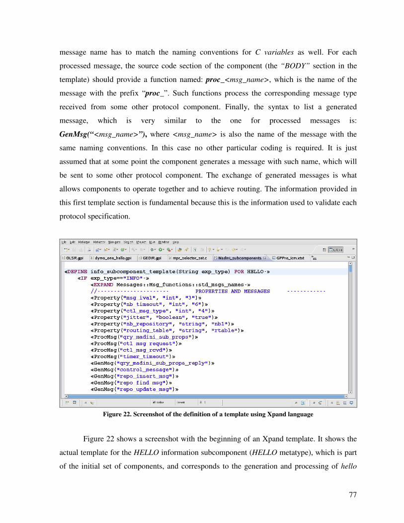
77
message name has to match the naming conventions for C variables as well. For each
processed message, the source code section of the component (the “BODY” section in the
template) should provide a function named: proc_<msg_name>, which is the name of the
message with the prefix “proc_”. Such functions process the corresponding message type
received from some other protocol component. Finally, the syntax to list a generated
message, which is very similar to the one for processed messages is:
GenMsg(“<msg_name>”), where <msg_name> is also the name of the message with the
same naming conventions. In this case no other particular coding is required. It is just
assumed that at some point the component generates a message with such name, which will
be sent to some other protocol component. The exchange of generated messages is what
allows components to operate together and to achieve routing. The information provided in
this first template section is fundamental because this is the information used to validate each
protocol specification.
Figure 22. Screenshot of the definition of a template using Xpand language
Figure 22 shows a screenshot with the beginning of an Xpand template. It shows the
actual template for the HELLO information subcomponent (HELLO metatype), which is part
of the initial set of components, and corresponds to the generation and processing of hello
78
messages. Figure 22 shows the “INFO” section of the component template with the list of
properties, processed messages and generated messages (in that order).
Protocol components are implemented as Xpand templates. However, all of the code
that actually implements each component is pure C language code that fits the template
structure. As discussed above, when the routing protocols are generated, components are
transformed into two files: one .c source file and one .h header file. The code going into the
header file comes mainly from the second section of the component template ("HEADERS")
and the code going into the source file comes mainly from the third section of the template
("BODY"). Additional code and functionalities to make the components fit the GP-Pro
architecture, and to communicate according to the interconnection model is added during the
generation process but without user intervention. It is totally transparent to the user (it can
only be seen by exploring the generated source files). In fact, the execution of GP-Pro
protocols is multi-threaded. Every message received by the MDC, by the internal component
process or by the output port of each component creates its own execution thread, which
exists for as long as the message is being processed by any of these units.
6.2.1 Component Operation
The general structure of every component template was described above. It is composed of
three different sections containing C code and configuration information. The three of them
are transformed to generate components implemented in pure C code. During protocol
generation, each component is enabled with the required capabilities to communicate
according to the interconnection model described in Chapter 5. An essential element of this
interconnection model, which exists in every component, is the MDC. The MDC contains
two tables with the names of the subcomponents and the names of the generated messages.
Both of these tables are filled up during a process called component Initialization. This
process is created for each component, during the generation process, and it can be found
inside the generated code as a function named <component_name>_initialize, where
<component_name> is the synonym given to the component in the protocol specification (as
described in Section 6.3). The initialization is the first process launched when the routing
protocol is executed. Its job is to prepare every component to operate according to the
79
interconnection model. The initialization process is sequentially executed by each component
according to its positioning in the hierarchy of components (see Figure 11 in page 61). It is
first executed by the component with the highest hierarchy, P, and then by each of its
subcomponents. Each of these subcomponents will follow suit by initializing themselves
first, and then all of their subcomponents before returning control to the parent component P.
Subsequent subcomponents will do the same until the lowest subcomponent level is reached.
Therefore, if we look at the hierarchy of components as a tree structure (see Figure 11), an
entire branch of components rooted at P will be initialized before the second subcomponent
of P is initialized (along with its corresponding subcomponents). This protocol initialization
process continues until all components have been initialized.
Once all the protocol components have been initialized, they are ready to exchange
messages with every other component and not only with immediate subcomponents. That is,
routing between components, as described in Section 5.3, can be achieved. However, some of
the protocol components need to perform some additional auto-configuration (e.g., create
some data structures, register timers with the event manager) before being able to properly
support the operation of the protocol. Therefore, an additional process called start is executed
by each component after initialization. It can be found inside the generated code as the
function named start(). Different from the function initialize that is automatically generated,
the start() function has to be implemented by the user in the component template. This start()
function has to be part of the third template section called (“BODY”). The default component
template shown in Appendix E shows the function declaration and its location in the
template. Thus, any task to be executed by each component after initialization, but before the
regular operation of the protocol, has to be performed by the start process. Similarly to
initialize, the start function is executed by the highest component in the protocol hierarchy
first, and then by each of its subcomponents. Once all of the protocol components have
executed the initialize and start processes, the routing protocol is ready to operate.
Finally, there is a third process that is executed by every protocol component: the stop
process. This process is executed when the operation of the routing protocol is to be stopped.
It can be found inside the generated code as the function named stop(). Similarly to the
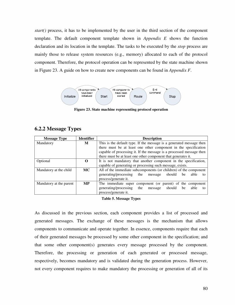
80
start() process, it has to be implemented by the user in the third section of the component
template. The default component template shown in Appendix E shows the function
declaration and its location in the template. The tasks to be executed by the stop process are
mainly those to release system resources (e.g., memory) allocated to each of the protocol
component. Therefore, the protocol operation can be represented by the state machine shown
in Figure 23. A guide on how to create new components can be found in Appendix F.
Figure 23. State machine representing protocol operation
6.2.2 Message Types
Message Type Identifier Description
Mandatory M This is the default type. If the message is a generated message then
there must be at least one other component in the specification
capable of processing it. If the message is a processed message then
there must be at least one other component that generates it.
Optional O It is not mandatory that another component in the specification,
capable of generating or processing such message, exists.
Mandatory at the child MC All of the immediate subcomponents (or children) of the component
generating/processing the message should be able to
process/generate it.
Mandatory at the parent MP The immediate super component (or parent) of the component
generating/processing the message should be able to
process/generate it.
Table 5. Message Types
As discussed in the previous section, each component provides a list of processed and
generated messages. The exchange of these messages is the mechanism that allows
components to communicate and operate together. In essence, components require that each
of their generated messages be processed by some other component in the specification; and
that some other component(s) generates every message processed by the component.
Therefore, the processing or generation of each generated or processed message,
respectively, becomes mandatory and is validated during the generation process. However,
not every component requires to make mandatory the processing or generation of all of its
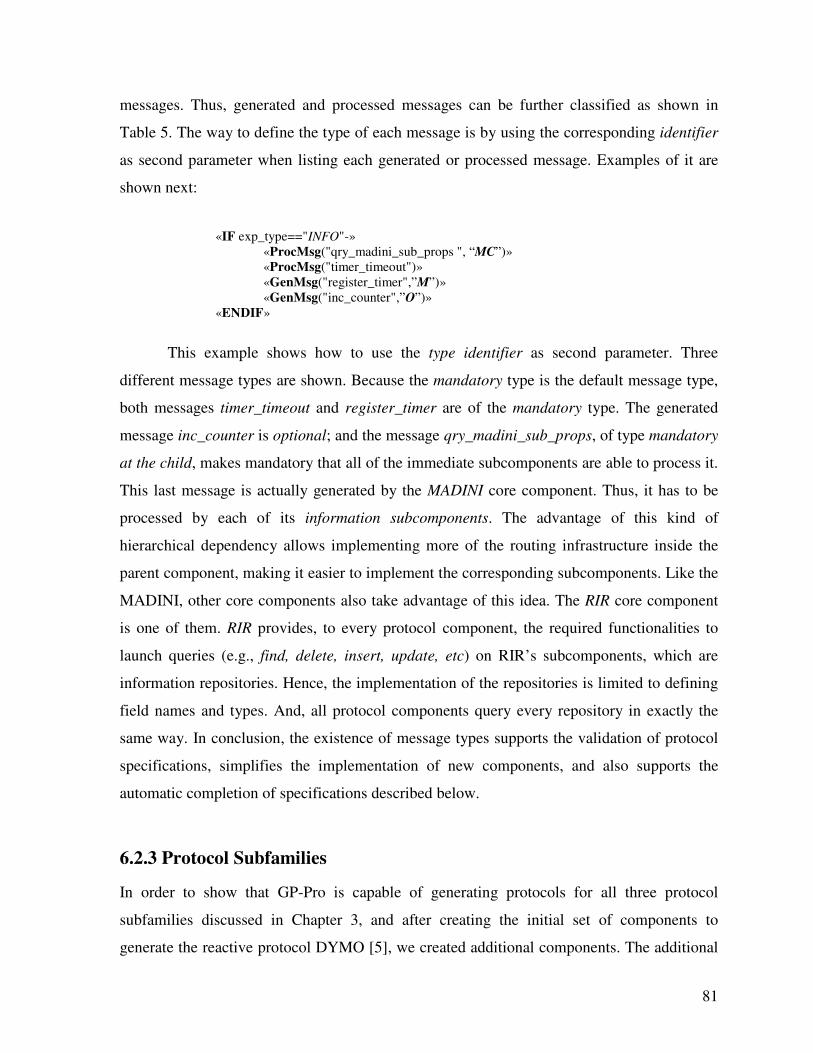
81
messages. Thus, generated and processed messages can be further classified as shown in
Table 5. The way to define the type of each message is by using the corresponding identifier
as second parameter when listing each generated or processed message. Examples of it are
shown next:
«IF exp_type=="INFO"-»
«ProcMsg("qry_madini_sub_props ", “MC”)»
«ProcMsg("timer_timeout")»
«GenMsg("register_timer",”M”)»
«GenMsg("inc_counter",”O”)»
«ENDIF»
This example shows how to use the type identifier as second parameter. Three
different message types are shown. Because the mandatory type is the default message type,
both messages timer_timeout and register_timer are of the mandatory type. The generated
message inc_counter is optional; and the message qry_madini_sub_props, of type mandatory
at the child, makes mandatory that all of the immediate subcomponents are able to process it.
This last message is actually generated by the MADINI core component. Thus, it has to be
processed by each of its information subcomponents. The advantage of this kind of
hierarchical dependency allows implementing more of the routing infrastructure inside the
parent component, making it easier to implement the corresponding subcomponents. Like the
MADINI, other core components also take advantage of this idea. The RIR core component
is one of them. RIR provides, to every protocol component, the required functionalities to
launch queries (e.g., find, delete, insert, update, etc) on RIR’s subcomponents, which are
information repositories. Hence, the implementation of the repositories is limited to defining
field names and types. And, all protocol components query every repository in exactly the
same way. In conclusion, the existence of message types supports the validation of protocol
specifications, simplifies the implementation of new components, and also supports the
automatic completion of specifications described below.
6.2.3 Protocol Subfamilies
In order to show that GP-Pro is capable of generating protocols for all three protocol
subfamilies discussed in Chapter 3, and after creating the initial set of components to
generate the reactive protocol DYMO [5], we created additional components. The additional
82
components allowed us to generate the proactive routing protocol OLSR [2], and the
position-based protocol Greedy [28]. Therefore, all nine core components of GP-Pro were
implemented along with their required subcomponents. The listing of components that were
created as part of this work, which are currently available is provided in Appendix C.
6.3 Protocol Specification
The previous two sections presented the way that the DSL was created and the method to
create protocol components by using Xpand templates. Now, we discuss how to write
protocol specifications according to the new DSL and based on the available components.
The DSL allows the user to describe each of the components that will be part of the routing
protocol, and to assign values to their configurable parameters. Additionally, the DSL allows
creating composite components and defining explicit interconnections between components.
The first protocol generated by GP-Pro according to a protocol specification was the DYMO
[5] protocol. DYMO shares many of the AODV [1] functionalities. However, it is easier to
implement and it is designed with future enhancements in mind. In DYMO, when a route to a
certain destination is required, a route discovery is initiated by broadcasting a route request
message. Each route request message is forwarded once by each node until reaching the
destination node. Then, the destination replies to the source node with a route reply message.
Each route request and each route reply message keep an ordered list of all the nodes they
passed through, so every receiver can immediately record a route back to the sender. To
detect link breakdowns DYMO makes use of Hello messages that are exchanged among one-
hop neighbors.
As mentioned before, a custom editor was created for the new DSL. Therefore, every
protocol specification should be written by using the custom editor in order to take advantage
of its support features such as: code completion and syntax and constraints checking. The
custom editor can be used inside Eclipse after GP-Pro and the new DSL have been installed
as Eclipse plug-ins. Next, we show an excerpt of the actual specification to generate the
DYMO [5] protocol. The full protocol specification can be found in Appendix D.
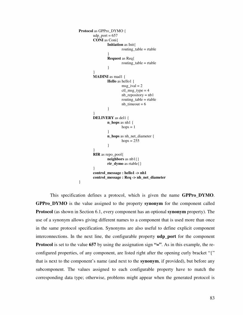
83
Protocol as GPPro_DYMO {
udp_port = 657
CONI as Coni{
Initiation as Init{
routing_table = rtable
}
Request as Req{
routing_table = rtable
}
}
MADINI as mad1 {
Hello as hello1 {
msg_ival = 2
ctl_msg_type = 4
nb_repository = nb1
routing_table = rtable
nb_timeout = 6
}
}
DELIVERY as del1 {
n_hops as nh1 {
hops = 1
}
n_hops as nh_net_diameter {
hops = 255
}
}
RIR as repo_pool{
neighbors as nb1{}
rir_dymo as rtable{}
}
control_message : hello1 -> nh1
control_message : Req -> nh_net_diameter
}
This specification defines a protocol, which is given the name GPPro_DYMO.
GPPro_DYMO is the value assigned to the property synonym for the component called
Protocol (as shown in Section 6.1, every component has an optional synonym property). The
use of a synonym allows giving different names to a component that is used more than once
in the same protocol specification. Synonyms are also useful to define explicit component
interconnections. In the next line, the configurable property udp_port for the component
Protocol is set to the value 657 by using the assignation sign “=”. As in this example, the re-
configured properties, of any component, are listed right after the opening curly bracket “{”
that is next to the component’s name (and next to the synonym, if provided), but before any
subcomponent. The values assigned to each configurable property have to match the
corresponding data type; otherwise, problems might appear when the generated protocol is
84
compiled. Protocol, which is the component of highest hierarchy, is the super-component of
all other components in the specification. In this example, it contains four subcomponents
called CONI, MADINI, DELIVERY and RIR. The subcomponents of any component in
the specification are defined inside the curly brackets (“{}”) that open right after the
component’s name. Therefore, when any given component needs to be extended with further
subcomponents, it is simply added to the corresponding subcomponent section right after its
declaration. In this way, components can be extended to as many subcomponent levels as
required by using this simple mechanism, and by explicitly defining the corresponding
component interconnections. Going back to our example, we can see that the subcomponent
CONI is composed of another two subcomponents called Initiation and Request, which
receive the synonyms Init and Req respectively, by using the reserved word “as”. Both of
them list one property named routing_table, which is set to rtable. rtable is the synonym
given to the subcomponent rir_dymo of the core component RIR. That means that a
repository that is part of the RIR can be used by any other component, just by setting a
property of that other component to the synonym given to the repository. The specification
also shows the core component MADINI, which includes the subcomponent Hello with
synonym hello1. The component hello1 lists several configurable properties and one of them
is set to the synonym of a second repository, which is nb1. The last core component in this
specification is DELIVERY. This component shows two subcomponents: nh1 and
nh_net_diameter that are both instances of the component n_hops. This is an example of
how the use of synonyms allows reusing the same component several times in the same
specification. In this case, the difference between these two components is the value that the
property hops is set to (1 and 255), which defines the maximum number of times that a
message, using such delivery mechanism, should be retransmitted. The way to define which
components are using each delivery mechanism is by making use of component
interconnections.
After the protocol subcomponents have been listed, the explicit component
interconnections have to be defined. In general, these connections have to be defined at the
end of the subcomponent section of the lowest component in the hierarchy which is also a
super-component for both, the sender and the destination components. The previous
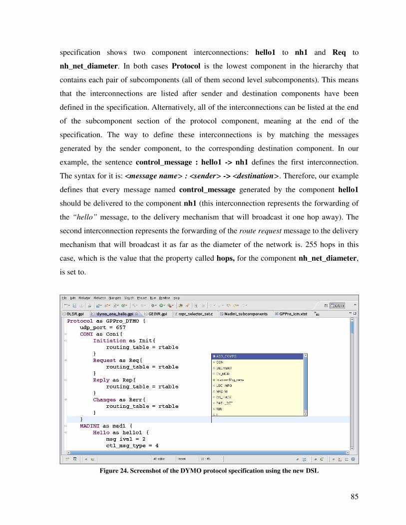
85
specification shows two component interconnections: hello1 to nh1 and Req to
nh_net_diameter. In both cases Protocol is the lowest component in the hierarchy that
contains each pair of subcomponents (all of them second level subcomponents). This means
that the interconnections are listed after sender and destination components have been
defined in the specification. Alternatively, all of the interconnections can be listed at the end
of the subcomponent section of the protocol component, meaning at the end of the
specification. The way to define these interconnections is by matching the messages
generated by the sender component, to the corresponding destination component. In our
example, the sentence control_message : hello1 -> nh1 defines the first interconnection.
The syntax for it is: <message name> : <sender> -> <destination>. Therefore, our example
defines that every message named control_message generated by the component hello1
should be delivered to the component nh1 (this interconnection represents the forwarding of
the “hello” message, to the delivery mechanism that will broadcast it one hop away). The
second interconnection represents the forwarding of the route request message to the delivery
mechanism that will broadcast it as far as the diameter of the network is. 255 hops in this
case, which is the value that the property called hops, for the component nh_net_diameter,
is set to.
Figure 24. Screenshot of the DYMO protocol specification using the new DSL
86
Figure 24 shows a screenshot of the protocol specification to generate the DYMO [5]
protocol. The figure shows the protocol specification along with a smaller pop up window,
which provides the code completion support specifically generated for the new DSL.
Interconnections are the source of information to fill up the message/destination table
of the MDC. On the other hand, the specification of subcomponents at several levels in the
component hierarchy is the source of information to fill up the subcomponents table of the
MDC.
From the previous example, we learned how a component (in this case Protocol) can
be extended by including additional subcomponents, and how those additional
subcomponents can be connected to each other. This same approach can be applied to any
other component, even to a basic component, until it becomes a complete routing protocol.
Both interconnections listed in the previous specification example are asynchronous
interconnections, denoted by the symbol “->”. It means that the sender component will
forward the message to the destination component, and immediately afterwards continues
processing any other pending task. Hence, the sender will not wait for the message to be
processed by the destination. This could be the most common operation mechanism for
interconnections. However, there are scenarios where the sender component needs to wait for
the processing of the message (plus some type of answer), before it continues with its regular
operation. An example of this scenario occurs when a component sends a query message to
an information repository and waits for an answer with the information matching the query.
Therefore, in this kind of scenario a second interconnection type is required, the synchronous
interconnection type. Components sending synchronous messages will wait for an answer
from the destination component before they continue their regular processing. Components
processing synchronous messages will generate a reply message with the same name plus the
prefix “reply_” (e.g., reply_find_query for message named find_query). The way to indicate
in the protocol specification that an interconnection is synchronous is by using the
bidirectional symbol “<->”, instead of the symbol “->”. The rest of the syntax to define the
interconnection remains the same.
87
6.4 Automatic Completion of Specifications
Each component is capable of processing and generating multiple message types. Ideally,
each message generated by a component (or output port), has to be interconnected to the
input port of another component that is capable of processing such message, which is also
part of the specification. However, the interconnection of every port for every component
might be a tedious and laborious task. Therefore, based on the fact that each component
clearly identifies the types of messages that it generates and processes, GP-Pro can
automatically complete the protocol specification on behalf of the user. The only scenarios
where GP-Pro might not be able to properly add the missing interconnections occur when
more than one component in the specification is capable of processing the same message
type, and no other advice (e.g., a hierarchical relationship) on how to interconnect the
components is available. Therefore, even though GP-Pro would create the missing
interconnection, it is recommended that, in this type of situations, the user makes sure that
she/he is the one defining those interconnections to achieve the expected behavior. An
example of such a situation is when more than one delivery mechanism (for control
messages) is listed in the protocol specification, because control messages could use any of
them. In that case GP-Pro would pick the first listed component that can process the message.
This is exactly the reason why two interconnections had to be listed as part of the protocol
specification shown in the example of Section 6.3; otherwise, the automatic completion
feature could have added all of the interconnections without the help of the user. As an
example of the aid provided by automatic completion, the full specification of the DYMO
implementation (see Appendix D) requires the definition of 145 component interconnections,
however, thanks to automatic completion, the user only has to define four (4) of them.
Adding missing interconnections between components is one of the methods to
automatically complete protocol specifications, however, it is not the only one supported by
GP-Pro. The second method is related to setting all of the configurable properties of each
component. As mentioned before, the configurable properties of each component are listed in
the INFO section of each component template. Each property is listed along with a default
value. Therefore, when any of these configurable properties is not included in the protocol
specification along with its corresponding value, GP-Pro will assign the default value to each
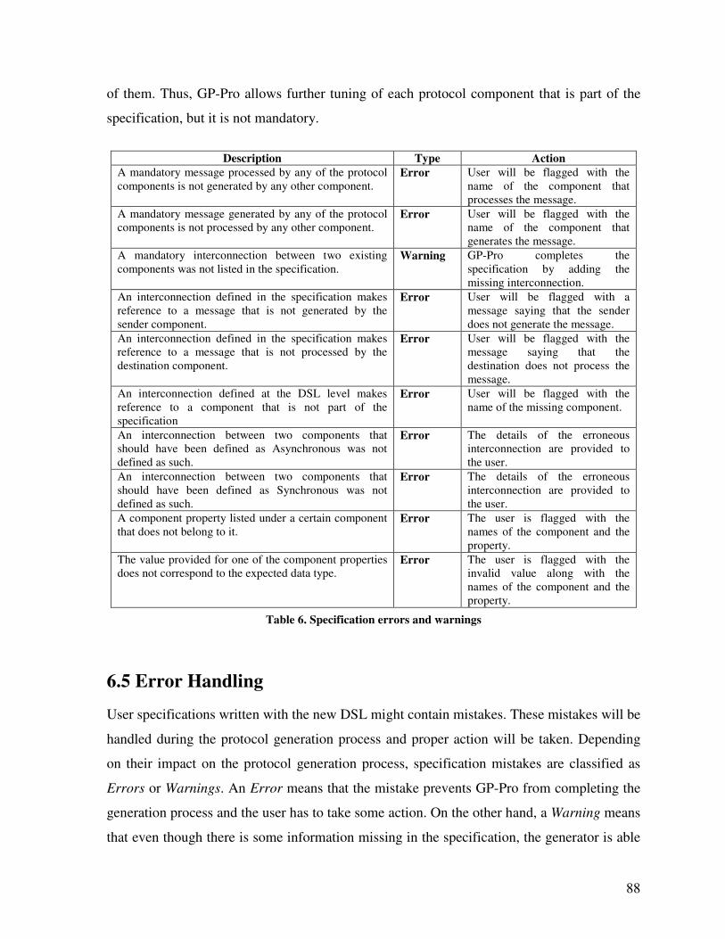
88
of them. Thus, GP-Pro allows further tuning of each protocol component that is part of the
specification, but it is not mandatory.
Description Type Action
A mandatory message processed by any of the protocol
components is not generated by any other component.
Error User will be flagged with the
name of the component that
processes the message.
A mandatory message generated by any of the protocol
components is not processed by any other component. Error User will be flagged with the
name of the component that
generates the message.
A mandatory interconnection between two existing
components was not listed in the specification.
Warning GP-Pro completes the
specification by adding the
missing interconnection.
An interconnection defined in the specification makes
reference to a message that is not generated by the
sender component.
Error User will be flagged with a
message saying that the sender
does not generate the message.
An interconnection defined in the specification makes
reference to a message that is not processed by the
destination component.
Error User will be flagged with the
message saying that the
destination does not process the
message.
An interconnection defined at the DSL level makes
reference to a component that is not part of the
specification
Error User will be flagged with the
name of the missing component.
An interconnection between two components that
should have been defined as Asynchronous was not
defined as such.
Error The details of the erroneous
interconnection are provided to
the user.
An interconnection between two components that
should have been defined as Synchronous was not
defined as such.
Error The details of the erroneous
interconnection are provided to
the user.
A component property listed under a certain component
that does not belong to it. Error The user is flagged with the
names of the component and the
property.
The value provided for one of the component properties
does not correspond to the expected data type. Error The user is flagged with the
invalid value along with the
names of the component and the
property.
Table 6. Specification errors and warnings
6.5 Error Handling
User specifications written with the new DSL might contain mistakes. These mistakes will be
handled during the protocol generation process and proper action will be taken. Depending
on their impact on the protocol generation process, specification mistakes are classified as
Errors or Warnings. An Error means that the mistake prevents GP-Pro from completing the
generation process and the user has to take some action. On the other hand, a Warning means
that even though there is some information missing in the specification, the generator is able
89
to provide it and continue with the generation process. Table 6 lists the mistakes that could
be made when writing the protocol specification. It also provides their classification, and the
action taken by GP-Pro.
6.6 Generation Time
In this section, we elaborate on the savings that can be obtained, in terms of reduced time to
generate a deployable protocol implementation, by using GP-Pro as the generation tool.
GP-Pro was created to speed up the generation time of ad hoc routing protocols ready
for deployment. It was designed as a software tool that could take a protocol specification as
an input, and would return a fully implemented protocol (assuming that all required
components are available), coded in C language and ready to be deployed as its output. A
proprietary DSL was created for our target domain in order to simplify the task of writing
new specifications. Each routing protocol is generated by assembling existing components,
which communicate with others according to an also proposed component interconnection
model. The tool was designed to be extensible, in a way that at anytime new components
could be added, and it could also accommodate further and forthcoming protocol features.
The first goal, aimed to prove the feasibility of GP-Pro, was to be able to generate a reactive
protocol while providing all of the previous capabilities. The choice of a reactive protocol, as
the first protocol, was due to its additional complexity in order to route packets when no path
is available, which requires interacting with the OS Kernel. Thus, DYMO was chosen as the
first protocol. This first goal was achieved after approximately eight months of work, and
after a case study that was used to verify that all the supportive software tools were the right
fit (about four more months).
The generation of one single protocol would not be enough to demonstrate the
protocol generation capabilities of GP-Pro. Therefore, after generating DYMO a second
protocol was generated, the well-known OLSR routing protocol. To generate this second
protocol, which belongs to the family of proactive protocols, more than 50% of the existing
routing components created to generate DYMO were reused. Thus, even though new routing

90
components had to be created, the generation of an OLSR implementation providing the core
functionalities described in [2], took about six weeks. In order to generate a deployable
routing protocol for each routing family, a third protocol was generated: the position-based
protocol called GREEDY. In this case, even more existing components were reused than
before, 75% of the components used by GREEDY existed already. It took about seven days
of work to create the required new components and generate a deployable version of
GREEDY. Hence, the time taken to generate GREEDY, compared to the time that took to
generate DYMO, was reduced from months to days (and to weeks in the case of OLSR).
Therefore, it becomes obvious that the more components are available, the shorter the
time required to generate each new protocol. This is independent of the fact that additional
components might be required by each new protocol. At the end, every time new components
are created, more components are available to be reused and the variety of protocols that can
be generated increases. More importantly, when all the components required by a new
protocol exist, meaning that no new components have to be created, the time to generate the
new protocol gets reduced to the time that takes to write the corresponding protocol
specification by using the proprietary DSL. To keep track of the components already
implemented, they should be grouped by the main component that they belong to. However,
further classification (based on component functionality), may be created for those
components that can be used in multiple main components. The specifications shown as
example in this document are between 39 and 60 lines long. Then, new protocols ready for
deployment over real networks could be generated in a matter of minutes. That is a drastic
reduction on the time required to generate deployable protocols, which, as shown in the next
chapter, perform proper and reliable routing at an affordable performance cost.
91
Chapter 7
Evaluation
This chapter discusses the evaluation of the protocol generator along with the generated
protocols once that GP-Pro was implemented. By implemented we mean here that the full
software tool has been created along with the protocol architecture and the component
interconnection model. Hence, GP-Pro provides freedom to select the components building
each new routing protocol. The fact that GP-Pro can be continuously extended by creating
new components that satisfy further and forthcoming protocol requirements suggests that we
cannot say, at any time, that it is actually complete. GP-Pro is a tool to generate ad hoc
routing protocols, which simplifies the development process. Therefore, in order to evaluate
it, we can either qualitatively compare it against some of the existing frameworks that share
similar objectives or, we can compare the performance of the generated protocols against
protocols generated by other frameworks or even handcrafted protocols. These alternatives
are discussed in the following sections. However, before elaborating on the evaluation
alternatives, we present the two other routing protocols that were generated with GP-Pro as
part of this work, which are also part of the performance evaluation.
7.1 Generated Protocols
GP-Pro aims to generate routing protocols for the three subfamilies described above:
proactive, reactive and position-based. Therefore, in order to show that GP-Pro is capable of
achieving its goal, we generated one protocol for each protocol subfamily. Section 6.3
presented an excerpt of the protocol specification to generate the reactive routing protocol
DYMO [5] and Appendix D contains the full protocol specification. Next, we present the
protocol specifications used to generate the proactive protocol OLSR [2], and the position-
based protocol GREEDY [28], both specifications are fully explained. Also, we introduce the
packet format used by the different control packets generated by each protocol. Finally, we
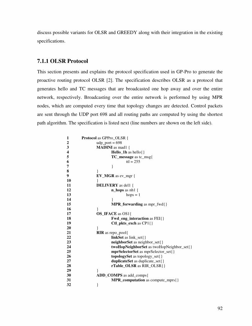
92
discuss possible variants for OLSR and GREEDY along with their integration in the existing
specifications.
7.1.1 OLSR Protocol
This section presents and explains the protocol specification used in GP-Pro to generate the
proactive routing protocol OLSR [2]. The specification describes OLSR as a protocol that
generates hello and TC messages that are broadcasted one hop away and over the entire
network, respectively. Broadcasting over the entire network is performed by using MPR
nodes, which are computed every time that topology changes are detected. Control packets
are sent through the UDP port 698 and all routing paths are computed by using the shortest
path algorithm. The specification is listed next (line numbers are shown on the left side).
1 Protocol as GPPro_OLSR {
2 udp_port = 698
3 MADINI as mad1 {
4 Hello_1h as hello{}
5 TC_message as tc_msg{
6 ttl = 255
7 }
8 }
9 EV_MGR as ev_mgr {
10 }
11 DELIVERY as del1 {
12 n_hops as nh1 {
13 hops = 1
14 }
15 MPR_forwarding as mpr_fwd{}
16 }
17 OS_IFACE as OS1{
18 Fwd_eng_interaction as FEI{}
19 Ctl_pkts_exch as CP1{}
20 }
21 RIR as repo_pool{
22 linkSet as link_set{}
23 neighborSet as neighbor_set{}
24 twoHopNeighborSet as twoHopNeighbor_set{}
25 mprSelectorSet as mprSelector_set{}
26 topologySet as topology_set{}
27 duplicateSet as duplicate_set{}
28 rTable_OLSR as RIR_OLSR{}
29 }
30 ADD_COMPS as add_comps{
31 MPR_computation as compute_mprs{}
32 }
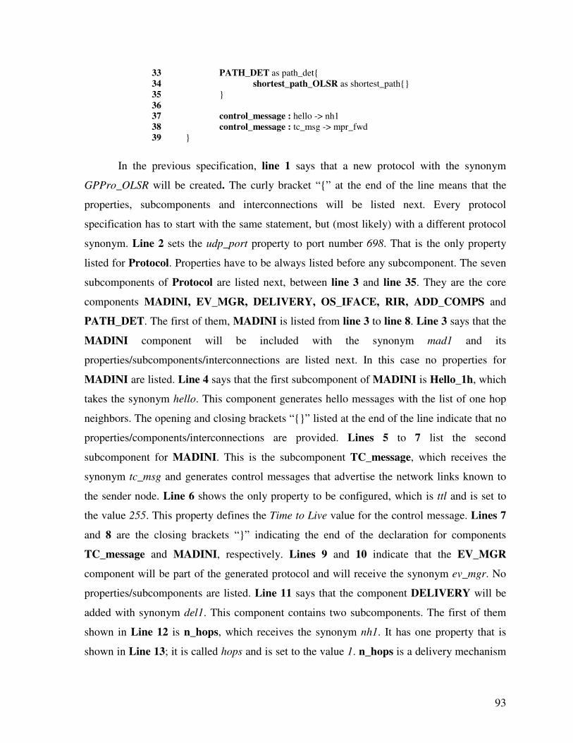
93
33 PATH_DET as path_det{
34 shortest_path_OLSR as shortest_path{}
35 }
36
37 control_message : hello -> nh1
38 control_message : tc_msg -> mpr_fwd
39 }
In the previous specification, line 1 says that a new protocol with the synonym
GPPro_OLSR will be created. The curly bracket “{” at the end of the line means that the
properties, subcomponents and interconnections will be listed next. Every protocol
specification has to start with the same statement, but (most likely) with a different protocol
synonym. Line 2 sets the udp_port property to port number 698. That is the only property
listed for Protocol. Properties have to be always listed before any subcomponent. The seven
subcomponents of Protocol are listed next, between line 3 and line 35. They are the core
components MADINI, EV_MGR, DELIVERY, OS_IFACE, RIR, ADD_COMPS and
PATH_DET. The first of them, MADINI is listed from line 3 to line 8. Line 3 says that the
MADINI component will be included with the synonym mad1 and its
properties/subcomponents/interconnections are listed next. In this case no properties for
MADINI are listed. Line 4 says that the first subcomponent of MADINI is Hello_1h, which
takes the synonym hello. This component generates hello messages with the list of one hop
neighbors. The opening and closing brackets “{}” listed at the end of the line indicate that no
properties/components/interconnections are provided. Lines 5 to 7 list the second
subcomponent for MADINI. This is the subcomponent TC_message, which receives the
synonym tc_msg and generates control messages that advertise the network links known to
the sender node. Line 6 shows the only property to be configured, which is ttl and is set to
the value 255. This property defines the Time to Live value for the control message. Lines 7
and 8 are the closing brackets “}” indicating the end of the declaration for components
TC_message and MADINI, respectively. Lines 9 and 10 indicate that the EV_MGR
component will be part of the generated protocol and will receive the synonym ev_mgr. No
properties/subcomponents are listed. Line 11 says that the component DELIVERY will be
added with synonym del1. This component contains two subcomponents. The first of them
shown in Line 12 is n_hops, which receives the synonym nh1. It has one property that is
shown in Line 13; it is called hops and is set to the value 1. n_hops is a delivery mechanism
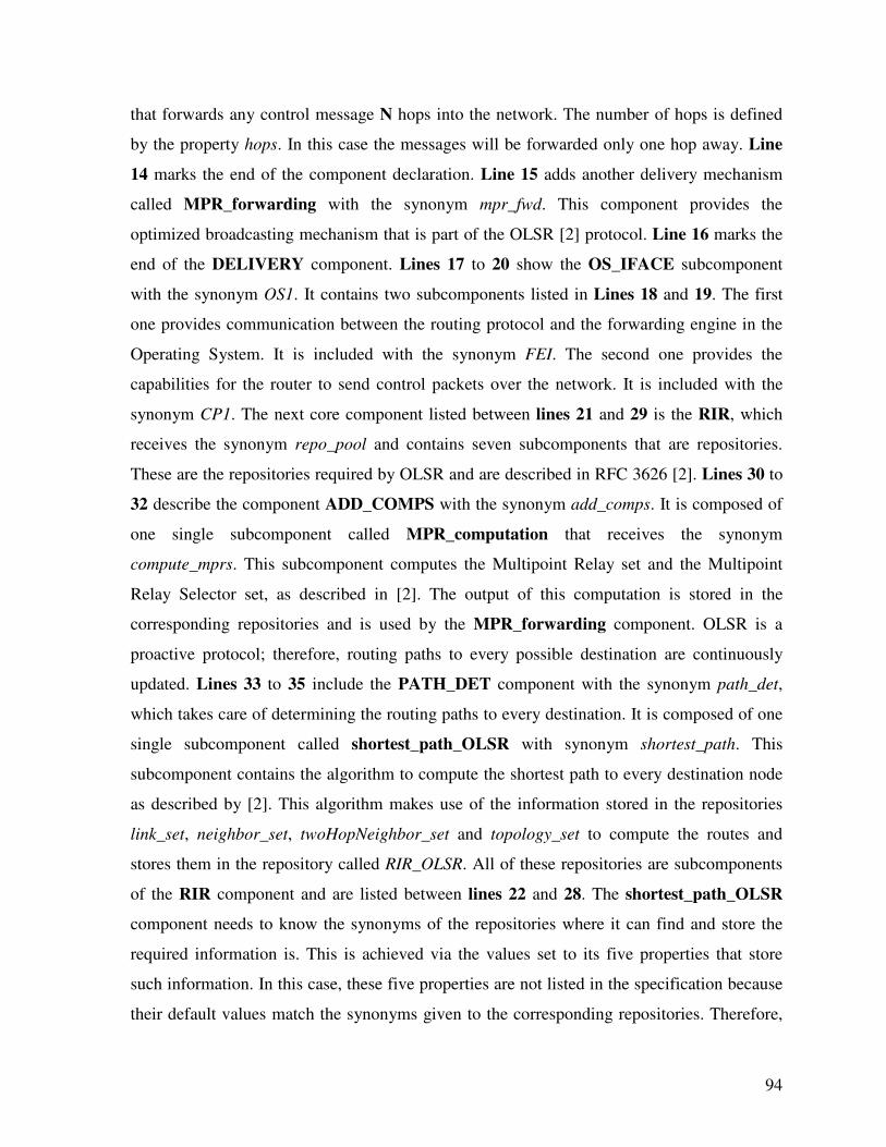
94
that forwards any control message N hops into the network. The number of hops is defined
by the property hops. In this case the messages will be forwarded only one hop away. Line
14 marks the end of the component declaration. Line 15 adds another delivery mechanism
called MPR_forwarding with the synonym mpr_fwd. This component provides the
optimized broadcasting mechanism that is part of the OLSR [2] protocol. Line 16 marks the
end of the DELIVERY component. Lines 17 to 20 show the OS_IFACE subcomponent
with the synonym OS1. It contains two subcomponents listed in Lines 18 and 19. The first
one provides communication between the routing protocol and the forwarding engine in the
Operating System. It is included with the synonym FEI. The second one provides the
capabilities for the router to send control packets over the network. It is included with the
synonym CP1. The next core component listed between lines 21 and 29 is the RIR, which
receives the synonym repo_pool and contains seven subcomponents that are repositories.
These are the repositories required by OLSR and are described in RFC 3626 [2]. Lines 30 to
32 describe the component ADD_COMPS with the synonym add_comps. It is composed of
one single subcomponent called MPR_computation that receives the synonym
compute_mprs. This subcomponent computes the Multipoint Relay set and the Multipoint
Relay Selector set, as described in [2]. The output of this computation is stored in the
corresponding repositories and is used by the MPR_forwarding component. OLSR is a
proactive protocol; therefore, routing paths to every possible destination are continuously
updated. Lines 33 to 35 include the PATH_DET component with the synonym path_det,
which takes care of determining the routing paths to every destination. It is composed of one
single subcomponent called shortest_path_OLSR with synonym shortest_path. This
subcomponent contains the algorithm to compute the shortest path to every destination node
as described by [2]. This algorithm makes use of the information stored in the repositories
link_set, neighbor_set, twoHopNeighbor_set and topology_set to compute the routes and
stores them in the repository called RIR_OLSR. All of these repositories are subcomponents
of the RIR component and are listed between lines 22 and 28. The shortest_path_OLSR
component needs to know the synonyms of the repositories where it can find and store the
required information is. This is achieved via the values set to its five properties that store
such information. In this case, these five properties are not listed in the specification because
their default values match the synonyms given to the corresponding repositories. Therefore,
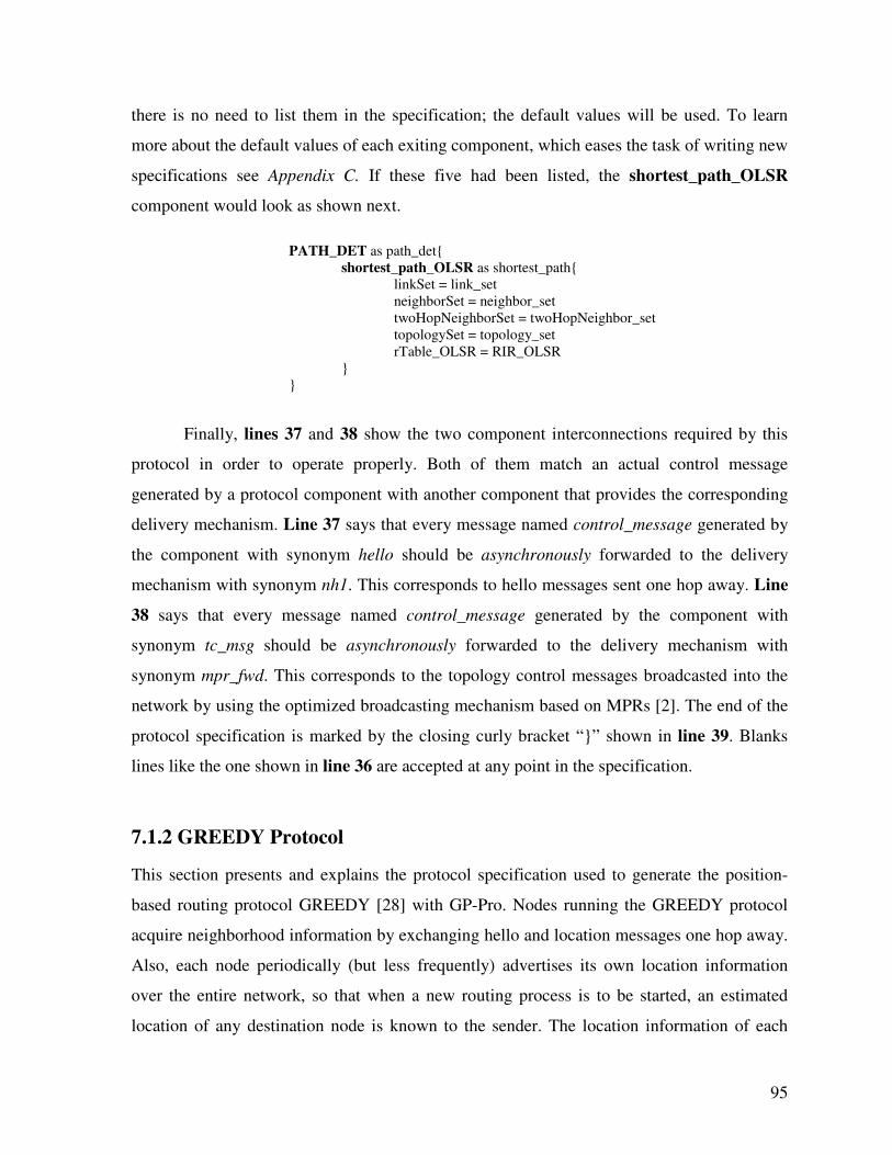
95
there is no need to list them in the specification; the default values will be used. To learn
more about the default values of each exiting component, which eases the task of writing new
specifications see Appendix C. If these five had been listed, the shortest_path_OLSR
component would look as shown next.
PATH_DET as path_det{
shortest_path_OLSR as shortest_path{
linkSet = link_set
neighborSet = neighbor_set
twoHopNeighborSet = twoHopNeighbor_set
topologySet = topology_set
rTable_OLSR = RIR_OLSR
}
}
Finally, lines 37 and 38 show the two component interconnections required by this
protocol in order to operate properly. Both of them match an actual control message
generated by a protocol component with another component that provides the corresponding
delivery mechanism. Line 37 says that every message named control_message generated by
the component with synonym hello should be asynchronously forwarded to the delivery
mechanism with synonym nh1. This corresponds to hello messages sent one hop away. Line
38 says that every message named control_message generated by the component with
synonym tc_msg should be asynchronously forwarded to the delivery mechanism with
synonym mpr_fwd. This corresponds to the topology control messages broadcasted into the
network by using the optimized broadcasting mechanism based on MPRs [2]. The end of the
protocol specification is marked by the closing curly bracket “}” shown in line 39. Blanks
lines like the one shown in line 36 are accepted at any point in the specification.
7.1.2 GREEDY Protocol
This section presents and explains the protocol specification used to generate the position-
based routing protocol GREEDY [28] with GP-Pro. Nodes running the GREEDY protocol
acquire neighborhood information by exchanging hello and location messages one hop away.
Also, each node periodically (but less frequently) advertises its own location information
over the entire network, so that when a new routing process is to be started, an estimated
location of any destination node is known to the sender. The location information of each
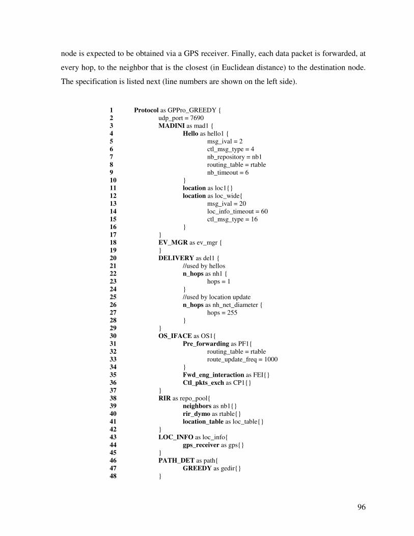
96
node is expected to be obtained via a GPS receiver. Finally, each data packet is forwarded, at
every hop, to the neighbor that is the closest (in Euclidean distance) to the destination node.
The specification is listed next (line numbers are shown on the left side).
1 Protocol as GPPro_GREEDY {
2 udp_port = 7690
3 MADINI as mad1 {
4 Hello as hello1 {
5 msg_ival = 2
6 ctl_msg_type = 4
7 nb_repository = nb1
8 routing_table = rtable
9 nb_timeout = 6
10 }
11 location as loc1{}
12 location as loc_wide{
13 msg_ival = 20
14 loc_info_timeout = 60
15 ctl_msg_type = 16
16 }
17 }
18 EV_MGR as ev_mgr {
19 }
20 DELIVERY as del1 {
21 //used by hellos
22 n_hops as nh1 {
23 hops = 1
24 }
25 //used by location update
26 n_hops as nh_net_diameter {
27 hops = 255
28 }
29 }
30 OS_IFACE as OS1{
31 Pre_forwarding as PF1{
32 routing_table = rtable
33 route_update_freq = 1000
34 }
35 Fwd_eng_interaction as FEI{}
36 Ctl_pkts_exch as CP1{}
37 }
38 RIR as repo_pool{
39 neighbors as nb1{}
40 rir_dymo as rtable{}
41 location_table as loc_table{}
42 }
43 LOC_INFO as loc_info{
44 gps_receiver as gps{}
45 }
46 PATH_DET as path{
47 GREEDY as gedir{}
48 }
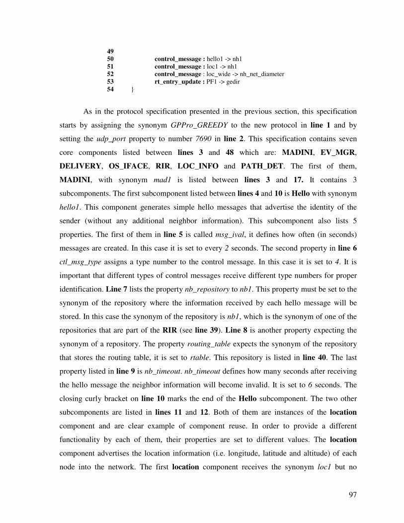
97
49
50 control_message : hello1 -> nh1
51 control_message : loc1 -> nh1
52 control_message : loc_wide -> nh_net_diameter
53 rt_entry_update : PF1 -> gedir
54 }
As in the protocol specification presented in the previous section, this specification
starts by assigning the synonym GPPro_GREEDY to the new protocol in line 1 and by
setting the udp_port property to number 7690 in line 2. This specification contains seven
core components listed between lines 3 and 48 which are: MADINI, EV_MGR,
DELIVERY, OS_IFACE, RIR, LOC_INFO and PATH_DET. The first of them,
MADINI, with synonym mad1 is listed between lines 3 and 17. It contains 3
subcomponents. The first subcomponent listed between lines 4 and 10 is Hello with synonym
hello1. This component generates simple hello messages that advertise the identity of the
sender (without any additional neighbor information). This subcomponent also lists 5
properties. The first of them in line 5 is called msg_ival, it defines how often (in seconds)
messages are created. In this case it is set to every 2 seconds. The second property in line 6
ctl_msg_type assigns a type number to the control message. In this case it is set to 4. It is
important that different types of control messages receive different type numbers for proper
identification. Line 7 lists the property nb_repository to nb1. This property must be set to the
synonym of the repository where the information received by each hello message will be
stored. In this case the synonym of the repository is nb1, which is the synonym of one of the
repositories that are part of the RIR (see line 39). Line 8 is another property expecting the
synonym of a repository. The property routing_table expects the synonym of the repository
that stores the routing table, it is set to rtable. This repository is listed in line 40. The last
property listed in line 9 is nb_timeout. nb_timeout defines how many seconds after receiving
the hello message the neighbor information will become invalid. It is set to 6 seconds. The
closing curly bracket on line 10 marks the end of the Hello subcomponent. The two other
subcomponents are listed in lines 11 and 12. Both of them are instances of the location
component and are clear example of component reuse. In order to provide a different
functionality by each of them, their properties are set to different values. The location
component advertises the location information (i.e. longitude, latitude and altitude) of each
node into the network. The first location component receives the synonym loc1 but no
98
properties are listed. This means that all of its properties will take the default values. For a
list of properties and default values of each component type see Appendix C. The second
location component receives the synonym loc_wide. Line 13 lists the first property called
msg_ival, which defines how often (in seconds) messages are sent; it is set to 20 (the default
value is 3). Line 14 lists the property called loc_info_timeout, which defines how many
seconds after the information has been received it is considered as invalid; it is set to 60 (the
default value is 12). Line 15 lists the last property called ctl_msg_type, which assigns a type
number to the control message. It is set to 16 (the default value is 15). Another property of
the location component that is not listed in the specification and thus takes the default value
is locationTable. This property expects the name of the repository that will store the location
information, the default value is loc_table, which is the synonym given to the repository
listed in line 41. Lines 18 to 19 add the EV_MGR component with synonym ev_mgr. Lines
20 to 29 include the DELIVERY component with synonym del1. This component contains
two subcomponents that are both instances of the component n_hops. The differences
between both of them are their synonyms and the value that the hops property is set to. The
first one has the synonym nh1 and the hops property is set to 1. The second one has the
synonym nh_net_diameter and the hops property is set to 255. This second delivery
subcomponent resembles regular broadcasting over the entire network (the value 255
represents the size of the network diameter). Lines 21 and 25 show that comments can be
written in the specification if the text is preceded by a double forward slash “//”. Lines 30 to
37 include the OS_IFACE component with synonym OS1. Different from the specification
of the OLSR protocol shown above, it includes a third subcomponent called Pre_forwarding
with synonym PF1. This subcomponent is meant to be used by reactive and position-based
protocols that do not maintain updated routes to every network destination. Therefore, this
component has to find a path or at least the next hop towards the destination, while buffering
data packets. Two properties are listed for this component. The first one is the routing_table
property shown in line 32. It is set to the synonym of the repository storing the routing table,
which is listed in line 40. The second property, route_update_freq, is set to 1000. This value
defines how often (in milliseconds), the validity of a routing table entry that is in use gets
updated. The description of DYMO [5] says that the validity of an entry in the routing table
has to be updated every time that a messages is received from, or forwarded to the
99
destination node of that entry. Therefore, when high data transmission rates are experienced,
this continuous update can potentially saturate the device running the routing protocol.
During our protocol performance evaluation using the DYMO protocol generated with GP-
PRO and using the DYMOUM [60] implementation, we experienced computer crashings
with both implementations when streaming high quality video. Therefore, we decided to limit
the frequency of such an update. Hence, this frequency can be controlled by increasing the
value assigned to the route_update_freq property. The higher the value, the less often the
update is performed. Frequency updates at a rate of one per second (1000 ms) provided
protocol performance stability. Thus, 1000 is used as the value for route_update_freq.
Lines 38 to 42 add the RIR component that includes the three repositories already
mentioned as its subcomponents. Lines 43 to 45 include the LOC_INFO core component
with synonym loc_info. This component, which is responsible for providing the location
information of the node running the routing protocol, is composed of one subcomponent
called gps_receiver with synonym gps. The component gps_receiver provides the current
location information of the host. It assumes the existence of a system file where location
information collected by a GPS receiver gets updated. The default path for such a file is
"/home/greedy/host_location.dat", and can be modified by resetting the property file_path of
the gps_receiver component. Lines 46 to 48 list the PATH_DET component with synonym
path. It contains one single subcomponent called GREEDY with synonym gedir. This
component selects the next hop for every data transmission according to the GREEDY [28]
protocol. That is, the next hop is the neighbor node that is the closest (Euclidean distance), to
the destination. Finally, lines 50 to 53 list the required component interconnections. Line 50
to 52 say that every control_message generated by the components with synonym hello1 and
loc1 should be forwarded to the delivery mechanism nh1; and every control_message
generated by the component with synonym loc_wide should be forwarded to the delivery
mechanism nh_net_diameter. That is, hello messages generated every 2 seconds by hello1
and location information messages generated every 3 seconds by loc1 will be broadcast one-
hop away. On the other hand, location information messages generated every 20 seconds by
loc_wide will be broadcasted over the entire network. The last interconnection, shown in line
53, means that every rt_entry_update message generated by PF1, which requests the update
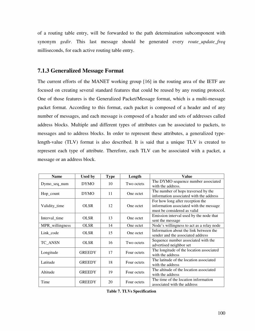
100
of a routing table entry, will be forwarded to the path determination subcomponent with
synonym gedir. This last message should be generated every route_update_freq
milliseconds, for each active routing table entry.
7.1.3 Generalized Message Format
The current efforts of the MANET working group [16] in the routing area of the IETF are
focused on creating several standard features that could be reused by any routing protocol.
One of those features is the Generalized Packet/Message format, which is a multi-message
packet format. According to this format, each packet is composed of a header and of any
number of messages, and each message is composed of a header and sets of addresses called
address blocks. Multiple and different types of attributes can be associated to packets, to
messages and to address blocks. In order to represent these attributes, a generalized type-
length-value (TLV) format is also described. It is said that a unique TLV is created to
represent each type of attribute. Therefore, each TLV can be associated with a packet, a
message or an address block.
Name Used by Type Length Value
Dymo_seq_num DYMO 10 Two octets The DYMO sequence number associated
with the address.
Hop_count DYMO 11 One octet The number of hops traversed by the
information associated with the address
Validity_time OLSR 12 One octet
For how long after reception the
information associated with the message
must be considered as valid
Interval_time OLSR 13 One octet Emission interval used by the node that
sent the message
MPR_willingness OLSR 14 One octet Node’s willingness to act as a relay node
Link_code OLSR 15 One octet Information about the link between the
sender and the associated address
TC_ANSN OLSR 16 Two octets Sequence number associated with the
advertised neighbor set
Longitude GREEDY 17 Four octets The longitude of the location associated
with the address
Latitude GREEDY 18 Four octets The latitude of the location associated
with the address
Altitude GREEDY 19 Four octets The altitude of the location associated
with the address
Time GREEDY 20 Four octets The time of the location information
associated with the address
Table 7. TLVs Specification
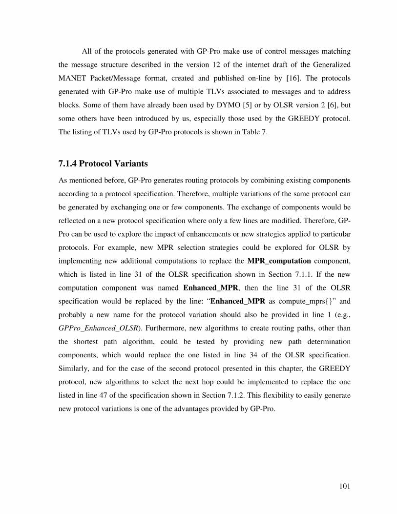
101
All of the protocols generated with GP-Pro make use of control messages matching
the message structure described in the version 12 of the internet draft of the Generalized
MANET Packet/Message format, created and published on-line by [16]. The protocols
generated with GP-Pro make use of multiple TLVs associated to messages and to address
blocks. Some of them have already been used by DYMO [5] or by OLSR version 2 [6], but
some others have been introduced by us, especially those used by the GREEDY protocol.
The listing of TLVs used by GP-Pro protocols is shown in Table 7.
7.1.4 Protocol Variants
As mentioned before, GP-Pro generates routing protocols by combining existing components
according to a protocol specification. Therefore, multiple variations of the same protocol can
be generated by exchanging one or few components. The exchange of components would be
reflected on a new protocol specification where only a few lines are modified. Therefore, GP-
Pro can be used to explore the impact of enhancements or new strategies applied to particular
protocols. For example, new MPR selection strategies could be explored for OLSR by
implementing new additional computations to replace the MPR_computation component,
which is listed in line 31 of the OLSR specification shown in Section 7.1.1. If the new
computation component was named Enhanced_MPR, then the line 31 of the OLSR
specification would be replaced by the line: “Enhanced_MPR as compute_mprs{}” and
probably a new name for the protocol variation should also be provided in line 1 (e.g.,
GPPro_Enhanced_OLSR). Furthermore, new algorithms to create routing paths, other than
the shortest path algorithm, could be tested by providing new path determination
components, which would replace the one listed in line 34 of the OLSR specification.
Similarly, and for the case of the second protocol presented in this chapter, the GREEDY
protocol, new algorithms to select the next hop could be implemented to replace the one
listed in line 47 of the specification shown in Section 7.1.2. This flexibility to easily generate
new protocol variations is one of the advantages provided by GP-Pro.
102
7.2 Comparing GP-Pro against Existing Frameworks
The first method to evaluate GP-Pro consists of qualitatively comparing it against other
existing frameworks that also support the implementation of communication protocols.
Therefore, the comparison is made in terms of the support that each of them provides to the
protocol implementation process.
GP-Pro ASL
[15]
X-Kernel
[11]
ACE
[12]
XORP
[39]
Click
[23]
CBR
[45]
PIX
[13]
Available to the public ○ ● ● ● ● ● ●
Domain specific ● ○ ●
Function libraries ● ●
API ●
Reusable elements ● ○ ● ●
Multi-platform ○ ● ●
Specification mechanism ● ● ●
Interconnection model ● ● ● ● ●
Protocols without coding ● ● ○
Code generation ● ●
Table 8. Qualitative comparison between existing frameworks
Table 8 shows a comparison between GP-Pro and the frameworks discussed in
Section 2.3, for different features that are important when supporting the implementation of
routing protocols. In Table 8, the filled circles (●) indicate that the framework provides the
indicated feature. On the other hand, empty circles (○) indicate that the feature is partially
provided, and the absence of a circle means that the feature is not provided at all. For the
eight frameworks shown in Table 8, all of them are available to the public except for CBR,
which as far as we know is not planned to be made public, and for GP-Pro, which has not
been made public yet, but it will be in the short term. Only three of these frameworks are
designed for the specific domain of ad hoc routing protocols. They are ASL, CBR and GP-
Pro. However, ASL only provides support for the family of reactive routing protocols.
In order to support the actual code writing task, ASL and ACE provide function
libraries while XORP provides an API. Instead of providing code writing support, Click,
CBR, PIX and GP-Pro create protocols by composition of reusable elements that do not
require further modification. Therefore, they encourage reuse of existing elements, and take
advantage of this in order to simplify and to speed up the protocol implementation process.
103
Click provides a similar method for protocol implementation than GP-Pro, unfortunately the
granularity of its elements is not fine enough to modularize a routing protocol into several
elements that can be reused and recombined. Actually, all of the ad hoc routing protocols that
have been implemented with Click are composed of only one or two Click elements.
Among all eight frameworks, only ACE and XORP are currently multi-platform.
GP-Pro was also designed to be multi-platform. The replacement of the OS Interface
component, by the one corresponding to the new target platform, would be the only change
required to generate a protocol for a different platform. However, no protocol for a platform
different than Linux has been generated with GP-Pro yet. On the other hand, when protocols
are implemented by composition of existing elements, the frameworks that do so can also
provide a specification mechanism for the user to request the desired protocol. Click, PIX
and GP-Pro are the only frameworks providing such mechanism in the form of a proprietary
DSL. Notice that the frameworks providing such a mechanism do not necessarily provide full
protocols, ready to be deployed, as an output. In order to define the way that each element
being part of a communication protocol interacts with others, an interconnection model is
required. The X-kernel, XORP, Click, PIX and GP-Pro define such interaction rules between
elements, which support framework extensibility.
Some of the frameworks are capable of creating protocols without coding at all
when all of the required elements already exist. That is the case for Click, PIX and GP-Pro.
In order to automatically assemble those existing elements and to generate the desired
protocol, only the protocol specification is required from the user. In the case of PIX,
although the desired protocol is generated, it still requires some coding in order to implement
packet processing and some additional functionality. Additionally, two of them are also
capable of generating new code automatically. That is the case of PIX and GP-Pro, both of
them are based on Generative Programming. The difference being that the protocols
generated by GP-Pro are complete and ready to be deployed. Thus, no further coding is
required.
104
From the previous analysis and comparison of the features provided by each
framework, it is possible to draw the following conclusions. First, no single framework
provides all of the listed development features, however, some of them provide enough
support to generate protocols without performing any coding. Second, we consider CBR, PIX
and GP-Pro as the top three development frameworks because all of them reduce
development to the point of generating protocols without coding at all. Third, PIX was the
first framework to take development support to the next level by providing the capability to
generate new code, however, it does not generate full protocol implementations and further
coding is required. Moreover, the development of PIX was stopped before it could have been
embraced by the research community. Fourth, even thought Click is not capable of
generating new code, it can generate protocols that are ready for deployment. Also, its
development has not stopped since it was first introduced, and it continues to be used by the
community. However, the coarse granularity of its packet processing elements prevents them
from being largely reused to generate new protocols. This might be due to the fact that its
scope is not specific to routing protocols. On the other hand, GP-Pro combines the best
features of PIX and Click and it is specific to the domain of ad hoc routing protocols. It
encourages reusability by allowing the implementation of fine granularity components, and
generates protocols ready for deployment. Additionally, different from PIX and Click, GP-
Pro was designed to be multi-platform. Therefore, we consider GP-Pro to provide the most
complete development support for the domain of ad hoc routing protocols. Also, the research
community has demonstrated interest on using GP-Pro during all the conferences where it
has been presented (see Section 1.5). Thus, we expect GP-Pro to be used by the research
community once that it is released to the public.
7.3 Comparing the Generated Protocols
In order to evaluate GP-Pro by comparing the performance of its generated protocols against
same protocols generated by other implementation mechanisms, the following alternatives
have to be considered:
1. Against protocols generated using other frameworks: Given a certain routing
protocol implemented with GP-Pro and with some other chosen framework, both
105
implementations would be deployed and compared over real networks. However, this
kind of comparison could be very time consuming and would involve a lot of
programming. It also may be difficult to argue that the implementation made by using
the other framework allows for fair comparison. This is due to the fact that the most
efficient implementation techniques of an alternative framework could be unknown to
new and inexperienced users and only be acquired with practical experience, which
could give an advantage to our own implementations using GP-Pro. The comparison
with such protocols, implemented by different frameworks, would make use of
quantitative performance metrics considering both protocols as black boxes, where
the implementation architecture would not considered.
2. Against handcrafted protocols: The problem to compare the generated protocols
against protocols generated by using some other framework is to justify fair
implementations of components or of any additional coding required after generation.
However, we want to demonstrate that the performance of the protocols generated
with GP-Pro makes worth the development of the entire tool. Therefore, the best
alternative is to select some of the reliable and well-known implementations of ad hoc
routing protocols (e.g., DYMO [60], OLSR [2]), implement the same protocols using
GP-Pro and deploy them both over a real network. In this case, each compared
protocol is considered as a black box, meaning that the implementation architecture is
not compared, and quantitative performance metrics are applied. We assume that each
handcrafted implementation was made to achieve the best possible performance.
After analyzing the possible evaluation mechanisms previously mentioned, we
decided to evaluate GP-Pro by quantitatively comparing two of its generated protocols
against their handcrafted counterparts. The protocols OLSR and DYMO generated by GP-
Pro are compared against OLSRD [73] and DYMOUM [60], respectively. Unfortunately,
there is no deployable implementation available of position-based routing protocols that we
are aware of. Thus, there is no handcrafted counterpart to compare against our
implementation of the GREEDY protocol. On the other hand, that makes our GREEDY
implementation another valuable contribution to the ad hoc routing community.
106
The evaluation of the generated protocols was performed in two parts. First, we tested
that the protocol implementations performed proper routing and we measured packet delivery
rates. Second, we measured the resources consumed by each protocol implementation in
standalone mode and while transmitting data, audio and video between pairs of source and
destination nodes over different network topologies. Each time, the implementation
generated with GP-Pro, for a chosen protocol, was compared against its handcrafted
counterpart over exactly the same conditions. The following sections describe our test-bed
along with each testing scenario.
7.3.1 Test-bed
With the objective of evaluating the performance of the routing protocols generated with GP-
Pro, and to compare them with their handcrafted counterparts, we set up a test-bed composed
of five laptop computers running the Fedora Core 5 distribution of Linux. Each computer
joins the ad hoc network by using Netgear dual band Wireless PC cards. The availability of
these five computers along with the use of MAC address filtering to emulate topology
changes, allows constructing routing paths up to 4 hops in length inside our testing lab.
Therefore, multiple scenarios of different topologies and path lengths can be created.
7.3.2 Proper Routing
The first evaluation scenario was created to test that each implementation performed proper
routing, meaning that it was able to create routing paths for each target destination. In order
to generate data traffic, the network tool ping was used to send groups of 30 data packets of
5042 bytes in length, one second apart (using the command: ping -c 30 -s 5000 -i 1). The
data packets were transmitted over network paths that were 1, 2, 3 and 4 hops long (up to 3
hops for DYMO, see explanation below), and the network had a linear bus topology. Packet
delivery rate and Round Trip Time (RTT) were used as performance metrics. Additionally, to
estimate the route discovery delay experienced by reactive protocols, ping was used to
measure the elapsed time between the initiation of a new route discovery and the reception of
the acknowledgment for the first packet sent. The metric unit for all time values shown in
this section is milliseconds.
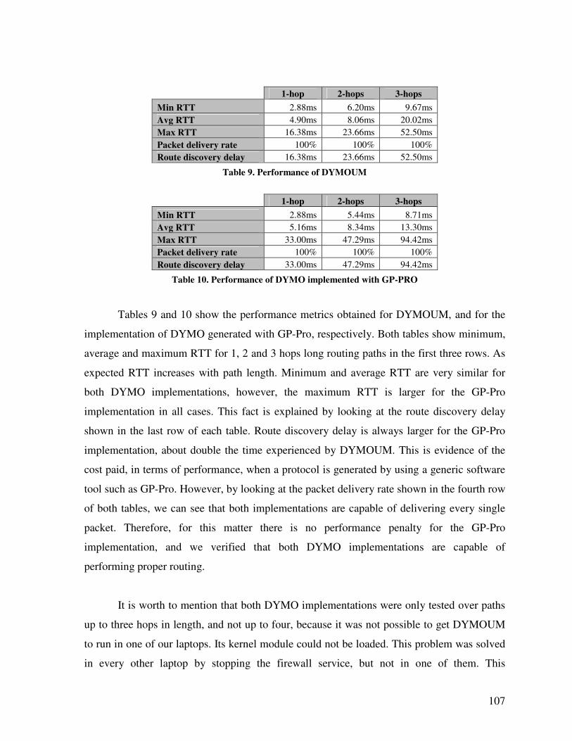
107
1-hop 2-hops 3-hops
Min RTT 2.88ms 6.20ms 9.67ms
Avg RTT 4.90ms 8.06ms 20.02ms
Max RTT 16.38ms 23.66ms 52.50ms
Packet delivery rate 100% 100% 100%
Route discovery delay 16.38ms 23.66ms 52.50ms
Table 9. Performance of DYMOUM
1-hop 2-hops 3-hops
Min RTT 2.88ms 5.44ms 8.71ms
Avg RTT 5.16ms 8.34ms 13.30ms
Max RTT 33.00ms 47.29ms 94.42ms
Packet delivery rate 100% 100% 100%
Route discovery delay 33.00ms 47.29ms 94.42ms
Table 10. Performance of DYMO implemented with GP-PRO
Tables 9 and 10 show the performance metrics obtained for DYMOUM, and for the
implementation of DYMO generated with GP-Pro, respectively. Both tables show minimum,
average and maximum RTT for 1, 2 and 3 hops long routing paths in the first three rows. As
expected RTT increases with path length. Minimum and average RTT are very similar for
both DYMO implementations, however, the maximum RTT is larger for the GP-Pro
implementation in all cases. This fact is explained by looking at the route discovery delay
shown in the last row of each table. Route discovery delay is always larger for the GP-Pro
implementation, about double the time experienced by DYMOUM. This is evidence of the
cost paid, in terms of performance, when a protocol is generated by using a generic software
tool such as GP-Pro. However, by looking at the packet delivery rate shown in the fourth row
of both tables, we can see that both implementations are capable of delivering every single
packet. Therefore, for this matter there is no performance penalty for the GP-Pro
implementation, and we verified that both DYMO implementations are capable of
performing proper routing.
It is worth to mention that both DYMO implementations were only tested over paths
up to three hops in length, and not up to four, because it was not possible to get DYMOUM
to run in one of our laptops. Its kernel module could not be loaded. This problem was solved
in every other laptop by stopping the firewall service, but not in one of them. This
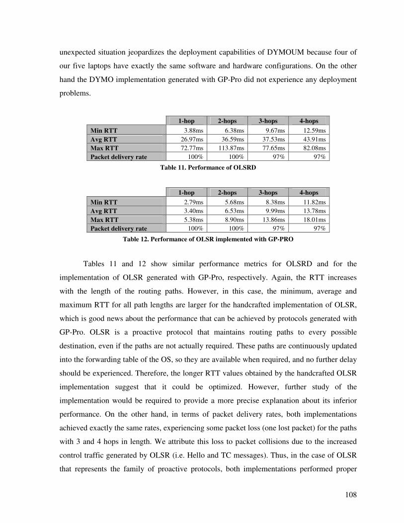
108
unexpected situation jeopardizes the deployment capabilities of DYMOUM because four of
our five laptops have exactly the same software and hardware configurations. On the other
hand the DYMO implementation generated with GP-Pro did not experience any deployment
problems.
1-hop 2-hops 3-hops 4-hops
Min RTT 3.88ms 6.38ms 9.67ms 12.59ms
Avg RTT 26.97ms 36.59ms 37.53ms 43.91ms
Max RTT 72.77ms 113.87ms 77.65ms 82.08ms
Packet delivery rate 100% 100% 97% 97%
Table 11. Performance of OLSRD
1-hop 2-hops 3-hops 4-hops
Min RTT 2.79ms 5.68ms 8.38ms 11.82ms
Avg RTT 3.40ms 6.53ms 9.99ms 13.78ms
Max RTT 5.38ms 8.90ms 13.86ms 18.01ms
Packet delivery rate 100% 100% 97% 97%
Table 12. Performance of OLSR implemented with GP-PRO
Tables 11 and 12 show similar performance metrics for OLSRD and for the
implementation of OLSR generated with GP-Pro, respectively. Again, the RTT increases
with the length of the routing paths. However, in this case, the minimum, average and
maximum RTT for all path lengths are larger for the handcrafted implementation of OLSR,
which is good news about the performance that can be achieved by protocols generated with
GP-Pro. OLSR is a proactive protocol that maintains routing paths to every possible
destination, even if the paths are not actually required. These paths are continuously updated
into the forwarding table of the OS, so they are available when required, and no further delay
should be experienced. Therefore, the longer RTT values obtained by the handcrafted OLSR
implementation suggest that it could be optimized. However, further study of the
implementation would be required to provide a more precise explanation about its inferior
performance. On the other hand, in terms of packet delivery rates, both implementations
achieved exactly the same rates, experiencing some packet loss (one lost packet) for the paths
with 3 and 4 hops in length. We attribute this loss to packet collisions due to the increased
control traffic generated by OLSR (i.e. Hello and TC messages). Thus, in the case of OLSR
that represents the family of proactive protocols, both implementations performed proper
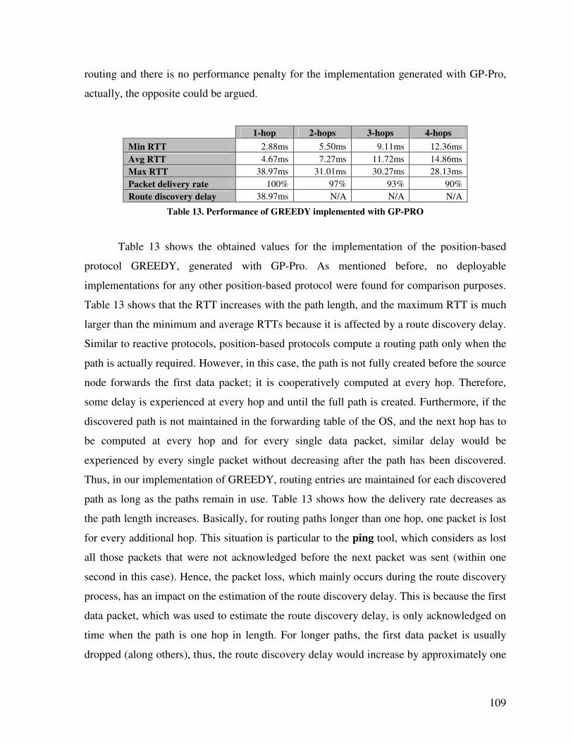
109
routing and there is no performance penalty for the implementation generated with GP-Pro,
actually, the opposite could be argued.
1-hop 2-hops 3-hops 4-hops
Min RTT 2.88ms 5.50ms 9.11ms 12.36ms
Avg RTT 4.67ms 7.27ms 11.72ms 14.86ms
Max RTT 38.97ms 31.01ms 30.27ms 28.13ms
Packet delivery rate 100% 97% 93% 90%
Route discovery delay 38.97ms N/A N/A N/A
Table 13. Performance of GREEDY implemented with GP-PRO
Table 13 shows the obtained values for the implementation of the position-based
protocol GREEDY, generated with GP-Pro. As mentioned before, no deployable
implementations for any other position-based protocol were found for comparison purposes.
Table 13 shows that the RTT increases with the path length, and the maximum RTT is much
larger than the minimum and average RTTs because it is affected by a route discovery delay.
Similar to reactive protocols, position-based protocols compute a routing path only when the
path is actually required. However, in this case, the path is not fully created before the source
node forwards the first data packet; it is cooperatively computed at every hop. Therefore,
some delay is experienced at every hop and until the full path is created. Furthermore, if the
discovered path is not maintained in the forwarding table of the OS, and the next hop has to
be computed at every hop and for every single data packet, similar delay would be
experienced by every single packet without decreasing after the path has been discovered.
Thus, in our implementation of GREEDY, routing entries are maintained for each discovered
path as long as the paths remain in use. Table 13 shows how the delivery rate decreases as
the path length increases. Basically, for routing paths longer than one hop, one packet is lost
for every additional hop. This situation is particular to the ping tool, which considers as lost
all those packets that were not acknowledged before the next packet was sent (within one
second in this case). Hence, the packet loss, which mainly occurs during the route discovery
process, has an impact on the estimation of the route discovery delay. This is because the first
data packet, which was used to estimate the route discovery delay, is only acknowledged on
time when the path is one hop in length. For longer paths, the first data packet is usually
dropped (along others), thus, the route discovery delay would increase by approximately one
110
second (the time between every ping packet) for every additional hop. That is why Table 13
shows most of the route discovery delays as: N/A, meaning not available. It should also be
noticed that all the RTT values shown in Table 13, which were reported by the ping tool,
only consider the packets that were acknowledged on time. That is why the Max RTT values
seem to decrease as the path length increases. But in reality, if the packets that experienced
the longest delays which were thought lost during the route discovery, were also considered,
more accurate values for Max RTT from 1 to 4 hops would be: 38.97ms, 1,031.01ms,
2,030.27ms and 3,028.13ms, respectively. That is, one second longer for each packet that
was lost until the route was discovered. Avg RTT values should be longer as well; however,
the growth trend as the path length increases would remain the same. On the other hand, Min
RTT values are not affected. Finally, from the results shown in Table 13, we can also
conclude that the capability of GREEDY to perform proper routing has been verified.
7.3.3 Resource Consumption
The evaluation performed in the previous section showed that all of the protocol
implementations were capable of constructing the required routing paths. Their only
performance disadvantage, compared to their handcrafted counterparts, was a longer route
discovery delay experienced by the DYMO implementation. Next, we evaluate the
computing resources consumed by each protocol implementation, which are expected to be
higher for the implementations generated with GP-Pro.
Computing resources consumed by each implementation were measured in two
running modes. First, while running each routing protocol in standalone mode; and second,
while transmitting data, audio and video from a sender to a destination node. Each of these
scenarios is described below.
7.3.3.1 Standalone Mode
In order to measure the amount of resources consumed by each protocol implementation
while running in standalone mode, the size of the binary file and the amount of consumed
physical memory were used as metrics.
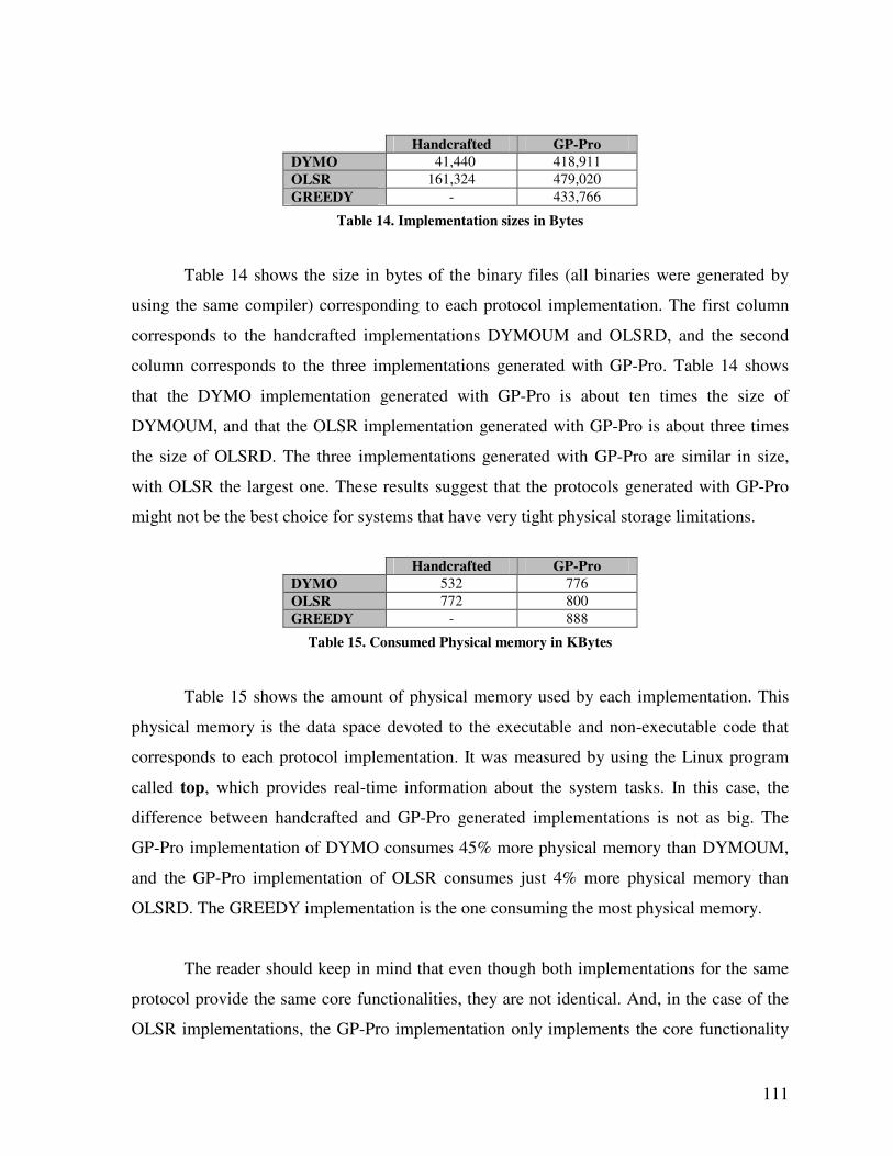
111
Handcrafted GP-Pro
DYMO 41,440 418,911
OLSR 161,324 479,020
GREEDY - 433,766
Table 14. Implementation sizes in Bytes
Table 14 shows the size in bytes of the binary files (all binaries were generated by
using the same compiler) corresponding to each protocol implementation. The first column
corresponds to the handcrafted implementations DYMOUM and OLSRD, and the second
column corresponds to the three implementations generated with GP-Pro. Table 14 shows
that the DYMO implementation generated with GP-Pro is about ten times the size of
DYMOUM, and that the OLSR implementation generated with GP-Pro is about three times
the size of OLSRD. The three implementations generated with GP-Pro are similar in size,
with OLSR the largest one. These results suggest that the protocols generated with GP-Pro
might not be the best choice for systems that have very tight physical storage limitations.
Handcrafted GP-Pro
DYMO 532 776
OLSR 772 800
GREEDY - 888
Table 15. Consumed Physical memory in KBytes
Table 15 shows the amount of physical memory used by each implementation. This
physical memory is the data space devoted to the executable and non-executable code that
corresponds to each protocol implementation. It was measured by using the Linux program
called top, which provides real-time information about the system tasks. In this case, the
difference between handcrafted and GP-Pro generated implementations is not as big. The
GP-Pro implementation of DYMO consumes 45% more physical memory than DYMOUM,
and the GP-Pro implementation of OLSR consumes just 4% more physical memory than
OLSRD. The GREEDY implementation is the one consuming the most physical memory.
The reader should keep in mind that even though both implementations for the same
protocol provide the same core functionalities, they are not identical. And, in the case of the
OLSR implementations, the GP-Pro implementation only implements the core functionality
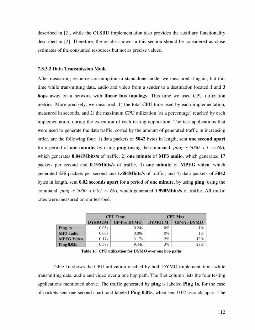
112
described in [2], while the OLSRD implementation also provides the auxiliary functionality
described in [2]. Therefore, the results shown in this section should be considered as close
estimates of the consumed resources but not as precise values.
7.3.3.2 Data Transmission Mode
After measuring resource consumption in standalone mode, we measured it again, but this
time while transmitting data, audio and video from a sender to a destination located 1 and 3
hops away on a network with linear bus topology. This time we used CPU utilization
metrics. More precisely, we measured: 1) the total CPU time used by each implementation,
measured in seconds, and 2) the maximum CPU utilization (as a percentage) reached by each
implementation, during the execution of each testing application. The test applications that
were used to generate the data traffic, sorted by the amount of generated traffic in increasing
order, are the following four: 1) data packets of 5042 bytes in length, sent one second apart
for a period of one minute, by using ping (using the command: ping -s 5000 -i 1 -w 60),
which generates 0.041Mbits/s of traffic, 2) one minute of MP3 audio, which generated 17
packets per second and 0.19Mbits/s of traffic, 3) one minute of MPEG video, which
generated 155 packets per second and 1.684Mbits/s of traffic, and 4) data packets of 5042
bytes in length, sent 0.02 seconds apart for a period of one minute, by using ping (using the
command: ping -s 5000 -i 0.02 -w 60), which generated 1.990Mbits/s of traffic. All traffic
rates were measured on our test-bed.
CPU Time CPU Max
DYMOUM GP-Pro DYMO DYMOUM GP-Pro DYMO
Ping 1s 0.03s 0.24s 0% 1%
MP3 audio 0.03s 0.09s 0% 1%
MPEG Video 0.17s 3.17s 2% 12%
Ping 0.02s 0.59s 9.44s 3% 28%
Table 16. CPU utilization for DYMO over one hop paths
Table 16 shows the CPU utilization reached by both DYMO implementations while
transmitting data, audio and video over a one hop path. The first column lists the four testing
applications mentioned above. The traffic generated by ping is labeled Ping 1s, for the case
of packets sent one second apart, and labeled Ping 0.02s, when sent 0.02 seconds apart. The
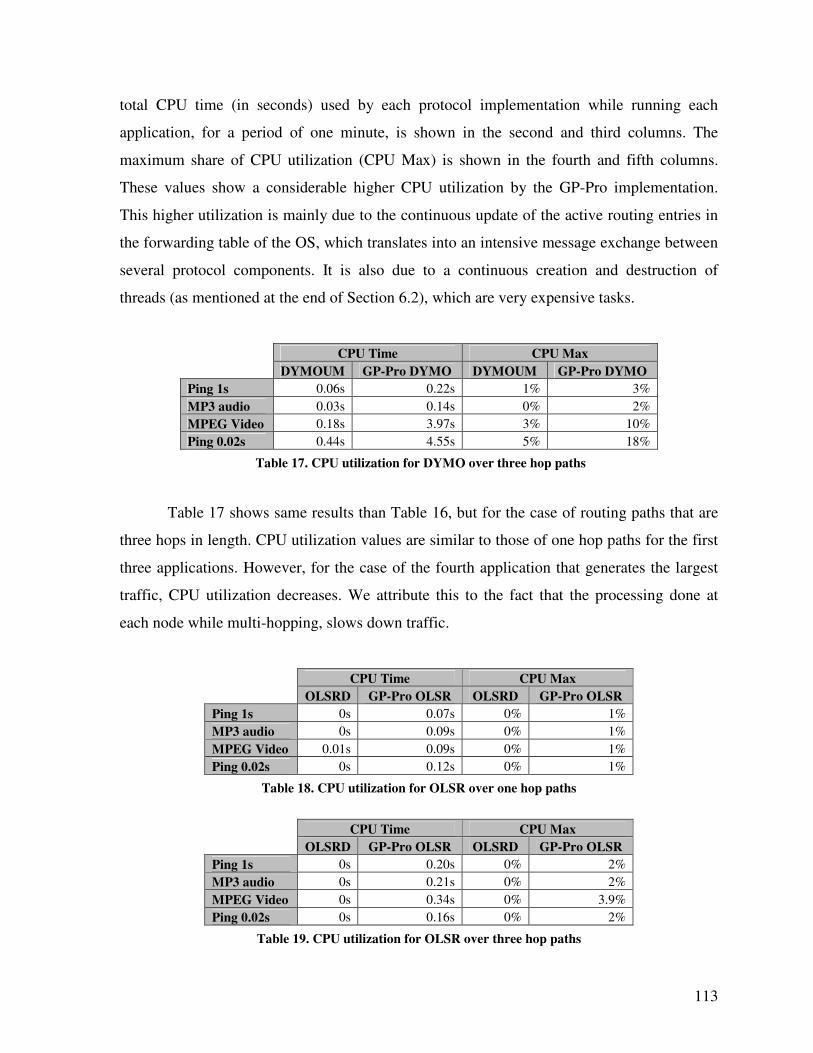
113
total CPU time (in seconds) used by each protocol implementation while running each
application, for a period of one minute, is shown in the second and third columns. The
maximum share of CPU utilization (CPU Max) is shown in the fourth and fifth columns.
These values show a considerable higher CPU utilization by the GP-Pro implementation.
This higher utilization is mainly due to the continuous update of the active routing entries in
the forwarding table of the OS, which translates into an intensive message exchange between
several protocol components. It is also due to a continuous creation and destruction of
threads (as mentioned at the end of Section 6.2), which are very expensive tasks.
CPU Time CPU Max
DYMOUM GP-Pro DYMO DYMOUM GP-Pro DYMO
Ping 1s 0.06s 0.22s 1% 3%
MP3 audio 0.03s 0.14s 0% 2%
MPEG Video 0.18s 3.97s 3% 10%
Ping 0.02s 0.44s 4.55s 5% 18%
Table 17. CPU utilization for DYMO over three hop paths
Table 17 shows same results than Table 16, but for the case of routing paths that are
three hops in length. CPU utilization values are similar to those of one hop paths for the first
three applications. However, for the case of the fourth application that generates the largest
traffic, CPU utilization decreases. We attribute this to the fact that the processing done at
each node while multi-hopping, slows down traffic.
CPU Time CPU Max
OLSRD GP-Pro OLSR OLSRD GP-Pro OLSR
Ping 1s 0s 0.07s 0% 1%
MP3 audio 0s 0.09s 0% 1%
MPEG Video 0.01s 0.09s 0% 1%
Ping 0.02s 0s 0.12s 0% 1%
Table 18. CPU utilization for OLSR over one hop paths
CPU Time CPU Max
OLSRD GP-Pro OLSR OLSRD GP-Pro OLSR
Ping 1s 0s 0.20s 0% 2%
MP3 audio 0s 0.21s 0% 2%
MPEG Video 0s 0.34s 0% 3.9%
Ping 0.02s 0s 0.16s 0% 2%
Table 19. CPU utilization for OLSR over three hop paths
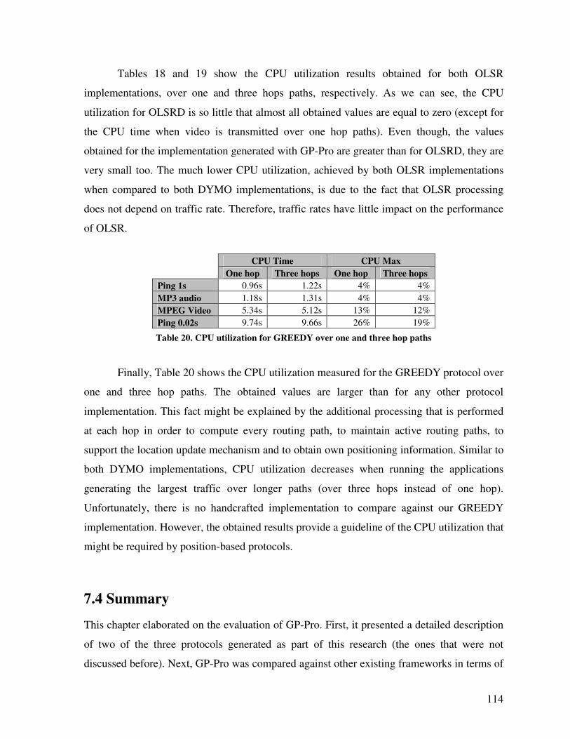
114
Tables 18 and 19 show the CPU utilization results obtained for both OLSR
implementations, over one and three hops paths, respectively. As we can see, the CPU
utilization for OLSRD is so little that almost all obtained values are equal to zero (except for
the CPU time when video is transmitted over one hop paths). Even though, the values
obtained for the implementation generated with GP-Pro are greater than for OLSRD, they are
very small too. The much lower CPU utilization, achieved by both OLSR implementations
when compared to both DYMO implementations, is due to the fact that OLSR processing
does not depend on traffic rate. Therefore, traffic rates have little impact on the performance
of OLSR.
CPU Time CPU Max
One hop Three hops One hop Three hops
Ping 1s 0.96s 1.22s 4% 4%
MP3 audio 1.18s 1.31s 4% 4%
MPEG Video 5.34s 5.12s 13% 12%
Ping 0.02s 9.74s 9.66s 26% 19%
Table 20. CPU utilization for GREEDY over one and three hop paths
Finally, Table 20 shows the CPU utilization measured for the GREEDY protocol over
one and three hop paths. The obtained values are larger than for any other protocol
implementation. This fact might be explained by the additional processing that is performed
at each hop in order to compute every routing path, to maintain active routing paths, to
support the location update mechanism and to obtain own positioning information. Similar to
both DYMO implementations, CPU utilization decreases when running the applications
generating the largest traffic over longer paths (over three hops instead of one hop).
Unfortunately, there is no handcrafted implementation to compare against our GREEDY
implementation. However, the obtained results provide a guideline of the CPU utilization that
might be required by position-based protocols.
7.4 Summary
This chapter elaborated on the evaluation of GP-Pro. First, it presented a detailed description
of two of the three protocols generated as part of this research (the ones that were not
discussed before). Next, GP-Pro was compared against other existing frameworks in terms of
115
the development support provided. Finally, the performance of well-know protocols
generated with GP-Pro was compared against the performance of their handcrafted
counterparts.
The detailed description of the specifications to generate the protocols OLSR and
GREEDY provided a full understanding on how to write protocol specification using GP-
Pro. Also, it discussed how different protocol variants could be generated by changing
current component selections. The comparison of GP-Pro against other existing frameworks
highlighted the most important development support features available, identified the top
development frameworks, and showed why we believe that GP-Pro provides the most
powerful development support for the domain of ad hoc routing protocols. Finally, the
performance evaluation of the protocols generated with GP-Pro demonstrated that they can
perform proper routing and that their performance is comparable to their handcrafted
counterparts. In some cases, the protocols generated with GP-Pro consumed more system
resources but their generation time was drastically reduced. That is the cost that we are
willing to pay in order to provide a fast protocol prototyping tool such as GP-Pro.
116
Chapter 8
Conclusions and Future Work
This thesis described existing problems and challenges to implement routing protocols for
MANETs. It also identified an approach to solve these problems by applying Generative
Programming to the domain of ad hoc routing protocols, and it introduced the GP-Pro
protocol generator for automatic generation of ad hoc routing protocols according to user
specifications. GP-Pro contributes to the field of mobile wireless networks by providing a
specification mechanism and a complete generation tool to quickly generate full routing
protocol implementations when all required components are available, and to maximize the
reusability of existing components when new nontrivial features are required. It also creates a
link with the field of software development by applying Generative Programming.
Furthermore, to support forthcoming network requirements, GP-Pro is designed to be
extensible and to allow the addition of new protocol features, in the form of new
components, at any time and without limitations. In the previous chapters, GP-Pro was
introduced in detail, along with the proposed architecture for ad hoc routing protocols and the
suggested component interconnection model. Additionally, protocols for all three families of
routing protocols were generated with GP-Pro and they were compared against their
handcrafted counterparts (when available). The comparison was performed by deploying and
testing, each protocol, over a real network that we set up as test-bed. Evaluation results show
that all generated protocols are capable of performing proper routing, and of achieving the
same packet delivery rates as their handcrafted counterparts. GP-Pro is a generic tool that
drastically reduces the time to generate new protocols. The reduction in development time
was expected to introduce a cost in terms of efficiency. This cost, measured in terms of
consumed resources from the host system, was obvious in the case of the reactive protocol
DYMO, but barely noticeable for the proactive protocol OLSR. On the other hand, we
showed that the more routing components exist, the shorter the time to generate new
protocols becomes. And, when all required components are available, generation time gets
117
reduced to the time that takes to write a protocol specification, about 50 lines long. No other
existing framework can achieve this.
At the beginning of this research we defined what success would be, as: the capability
for GP-Pro to automatically generate a broad range of protocol variations, which were also
competitive with handcrafted protocol implementations. By competitive we meant that the
generated protocols should provide similar performance to their handcrafted counterparts,
while achieving a reasonable trade-off between efficiency and generation-time. We expected
a minimal generation time, but, most likely, a lower efficiency of the generated protocols.
The evaluation results presented in the Chapter 7, where the protocols generated by GP-Pro
achieved similar routing performance than their handcrafted counterparts, showed that we
achieved this at a reasonable resource consumption cost. And, also the fact that their
generation time was drastically reduced with the increase on the number of available
components, we can certainly conclude that what we have achieved is: satisfactory and actual
success.
Some additional and beneficial GP-Pro related efforts are still outstanding. For
example, it would be advantageous to add the capability to generate routing protocols for
multiple platforms, and not only for Linux. This capability would be provided by creating the
corresponding OS Interface components and subcomponents, for each other platform that is
to be supported. We are currently looking at the possibility of using the Protean Protocol
Prototyping Library (ProtoLib) developed by the Networks and Communication Systems
Branch of the U.S. Naval Research Laboratory, which provides interfacing support for
multiple platforms. Also, we would like to make GP-Pro public. That is, to give it to the
research community, so more researchers could take advantage of it, could test it, could
create additional components to provide further features, and perhaps they could enhance
GP-Pro too. This way we could also evaluate how short the GP-Pro learning curve actually
is. Because even though we assume that the creation of new components, in the form of
templates, which basically are pure C code, is not complicated; and, that protocol
specifications are pretty much listings of chosen components with some properties set
according to user preferences, the best evaluation will be obtained in the form of feedback
118
from new users. Finally, we would like to generate code that could be also fed into a network
simulator, that way the protocols generated with GP-Pro could be tested both through
simulation and through real deployments.
Through this doctoral research work, and this thesis document, we were able to
demonstrate that it is possible to generate complete protocol implementations that are ready
for deployment, by automatically assembling components according to a protocol
specification (as represented by Figure 25 in Appendix G). This specification is written in a
proprietary DSL that is presumably easy to learn and use. The cost of these benefits, which
was discussed in Chapter 7, could be considered expensive in the case of the generated
reactive protocol, but not so in the case of the proactive protocol. That is good news in
general for the protocols generated with GP-Pro. However, there are some improvements that
we have on mind, which could improve protocol performance and efficiency. These ideas are
discussed next. First, we would like to replace the hierarchical routing of messages between
protocol components, by direct communication between any pair of components. From an
implementation point of view, this could be achieved by providing n-1 function pointers, to
each of the n components building the routing protocol. These n-1 pointers would point to the
different functions handling the input ports of the other n-1 components. In this way direct
communication would be achieved, and many message transmissions between components
would be avoided along with their corresponding overhead. Second, as described at the end
of Section 6.2, one new thread is created for every message that is received by the MDC, by
the internal component process or by the output port of each component, and it exists until
completing the corresponding processing. This policy of creating and destroying threads in a
regular basis is likely consuming a considerable amount of system resources. Therefore, we
want to modify this policy by only creating a new thread when a message is first created by a
protocol component, and only destroying this thread when the message has been processed
by its final destination. All required processing for the same message should happen within
the same thread. We believe that these two optimizations would decrease CPU utilization.
Additionally, in order to decrease the implementation size, we would like to explore ways to
shrink our interconnection model, by further customizing each component interconnection
119
during the generation process. This way, a reduction in the size of the generated code should
be achieved.
On the other hand, in terms of the ease to use GP-Pro, we want to implement an
application hosting the GUI described in Section 4.1.3. Also, we would like this application
to maintain a database of existing components along with their generated and processed
messages. If this information were available, the completion of specifications would not be
limited to missing interconnections only; missing components could be handled as well.
Further specification validations could be performed if the listings of configurable properties,
for each component, were also available in the same database. The information available in
this database could also allow us to explore ways to define, and to represent, further
dependencies between components. Finally, we would like to enhance our DSL to allow
writing subjective protocol specifications. These specifications would not need to list every
single component to request the generation of a new protocol, just a few words, such as: QoS
aware protocol or energy aware protocol would be enough. To achieve this last goal, we
would need to create further component classifications according to the subjective features
that each component could provide.
120
Appendices
In the following pages we present seven appendices with useful information about key
elements of GP-Pro and about how to use GP-Pro to create new routing protocols. Appendix
A shows the entire DSL that was created for GP-Pro. Appendix B lists all the different
templates that were created to generate the first three protocols. Appendix C provides a
detailed description of each and every component that has been created for GP-Pro, so far.
Appendix D shows the entire protocol specification to create the DYMO protocol. It lists
every single component interconnection that would have to be defined if the automatic
completion feature (discussed in Section 6.4) had not been created. Appendix E provides a
default template that can be used to create every new protocol component. Appendix F
discusses how to create a new protocol component. Finally, Appendix G shows the logo that
we created to represent GP-Pro.
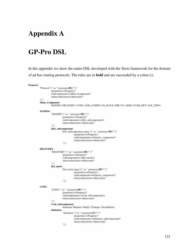
121
Appendix A
GP-Pro DSL
In this appendix we show the entire DSL developed with the Xtext framework for the domain
of ad hoc routing protocols. The rules are in bold and are succeeded by a colon (:).
Protocol :
"Protocol" (" as " synonym=ID)? "{"
(properties+=Property)*
(subcomponents+=Main_Component)*
(interconnections+=Interconn)*
"}";
Main_Component :
MADINI | DELIVERY | CONI | ADD_COMPS | OS_IFACE | RIR | EV_MGR | PATH_DET | LOC_INFO ;
MADINI :
"MADINI" (" as " synonym=ID)? "{"
(properties+=Property)*
(subcomponents+=Info_subcomponent)+
(interconnections+=Interconn)*
"}";
Info_subcomponent :
Info_subcomponent_types | (" as " synonym=ID)? "{"
(properties+=Property)*
(subcomponents+=Generic_component)*
(interconnections+=Interconn)*
"}";
DELIVERY :
"DELIVERY" (" as " synonym=ID)? "{"
(properties+=Property)*
(subcomponents+=Del_mech)+
(interconnections+=Interconn)*
"}";
Del_mech :
Del_mech_types | (" as " synonym=ID)? "{"
(properties+=Property)*
(subcomponents+=Generic_component)*
(interconnections+=Interconn)*
"}";
CONI :
"CONI" (" as " synonym=ID)? "{"
(properties+=Property)*
(subcomponents+=Coni_subcomponent)+
(interconnections+=Interconn)*
"}";
Coni_subcomponent :
Initiation | Request | Reply | Changes | Invalidation;
Initiation :
"Initiation" (" as " synonym=ID)? "{"
(properties+=Property)*
(subcomponents+=Initiation_subcomponent)*
(interconnections+=Interconn)*
"}";
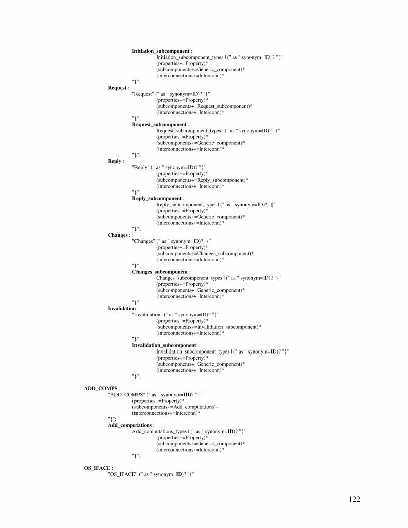
122
Initiation_subcomponent :
Initiation_subcomponent_types | (" as " synonym=ID)? "{"
(properties+=Property)*
(subcomponents+=Generic_component)*
(interconnections+=Interconn)*
"}";
Request :
"Request" (" as " synonym=ID)? "{"
(properties+=Property)*
(subcomponents+=Request_subcomponent)*
(interconnections+=Interconn)*
"}";
Request_subcomponent :
Request_subcomponent_types | (" as " synonym=ID)? "{"
(properties+=Property)*
(subcomponents+=Generic_component)*
(interconnections+=Interconn)*
"}";
Reply :
"Reply" (" as " synonym=ID)? "{"
(properties+=Property)*
(subcomponents+=Reply_subcomponent)*
(interconnections+=Interconn)*
"}";
Reply_subcomponent :
Reply_subcomponent_types | (" as " synonym=ID)? "{"
(properties+=Property)*
(subcomponents+=Generic_component)*
(interconnections+=Interconn)*
"}";
Changes :
"Changes" (" as " synonym=ID)? "{"
(properties+=Property)*
(subcomponents+=Changes_subcomponent)*
(interconnections+=Interconn)*
"}";
Changes_subcomponent :
Changes_subcomponent_types | (" as " synonym=ID)? "{"
(properties+=Property)*
(subcomponents+=Generic_component)*
(interconnections+=Interconn)*
"}";
Invalidation :
"Invalidation" (" as " synonym=ID)? "{"
(properties+=Property)*
(subcomponents+=Invalidation_subcomponent)*
(interconnections+=Interconn)*
"}";
Invalidation_subcomponent :
Invalidation_subcomponent_types | (" as " synonym=ID)? "{"
(properties+=Property)*
(subcomponents+=Generic_component)*
(interconnections+=Interconn)*
"}";
ADD_COMPS :
"ADD_COMPS" (" as " synonym=ID)? "{"
(properties+=Property)*
(subcomponents+=Add_computations)+
(interconnections+=Interconn)*
"}";
Add_computations :
Add_computations_types | (" as " synonym=ID)? "{"
(properties+=Property)*
(subcomponents+=Generic_component)*
(interconnections+=Interconn)*
"}";
OS_IFACE :
"OS_IFACE" (" as " synonym=ID)? "{"
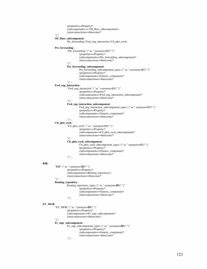
123
(properties+=Property)*
(subcomponents += OS_Iface_subcomponent)+
(interconnections+=Interconn)*
"}";
OS_Iface_subcomponent :
Pre_forwarding | Fwd_eng_interaction | Ctl_pkts_exch;
Pre_forwarding :
"Pre_forwarding" (" as " synonym=ID)? "{"
(properties+=Property)*
(subcomponents+=Pre_forwarding_subcomponent)*
(interconnections+=Interconn)*
"}";
Pre_forwarding_subcomponent :
Pre_forwarding_subcomponent_types | (" as " synonym=ID)? "{"
(properties+=Property)*
(subcomponents+=Generic_component)*
(interconnections+=Interconn)*
"}" ;
Fwd_eng_interaction :
"Fwd_eng_interaction" (" as " synonym=ID)? "{"
(properties+=Property)*
(subcomponents+=Fwd_eng_interaction_subcomponent)*
(interconnections+=Interconn)*
"}";
Fwd_eng_interaction_subcomponent :
Fwd_eng_interaction_subcomponent_types | (" as " synonym=ID)? "{"
(properties+=Property)*
(subcomponents+=Generic_component)*
(interconnections+=Interconn)*
"}" ;
Ctl_pkts_exch :
"Ctl_pkts_exch" (" as " synonym=ID)? "{"
(properties+=Property)*
(subcomponents+=Ctl_pkts_exch_subcomponent)*
(interconnections+=Interconn)*
"}";
Ctl_pkts_exch_subcomponent :
Ctl_pkts_exch_subcomponent_types | (" as " synonym=ID)? "{"
(properties+=Property)*
(subcomponents+=Generic_component)*
(interconnections+=Interconn)*
"}" ;
RIR :
"RIR" (" as " synonym=ID)? "{"
(properties+=Property)*
(subcomponents+=Routing_repository)+
(interconnections+=Interconn)*
"}";
Routing_repository :
Routing_repository_types | (" as " synonym=ID)? "{"
(properties+=Property)*
(subcomponents+=Generic_component)*
(interconnections+=Interconn)*
"}";
EV_MGR :
"EV_MGR" (" as " synonym=ID)? "{"
(properties+=Property)*
(subcomponents+=Ev_mgr_subcomponent)*
(interconnections+=Interconn)*
"}";
Ev_mgr_subcomponent :
Ev_mgr_subcomponent_types | (" as " synonym=ID)? "{"
(properties+=Property)*
(subcomponents+=Generic_component)*
(interconnections+=Interconn)*
"}";
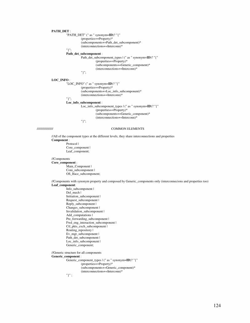
124
PATH_DET :
"PATH_DET" (" as " synonym=ID)? "{"
(properties+=Property)*
(subcomponents+=Path_det_subcomponent)*
(interconnections+=Interconn)*
"}";
Path_det_subcomponent :
Path_det_subcomponent_types | (" as " synonym=ID)? "{"
(properties+=Property)*
(subcomponents+=Generic_component)*
(interconnections+=Interconn)*
"}";
LOC_INFO :
"LOC_INFO" (" as " synonym=ID)? "{"
(properties+=Property)*
(subcomponents+=Loc_info_subcomponent)*
(interconnections+=Interconn)*
"}";
Loc_info_subcomponent :
Loc_info_subcomponent_types | (" as " synonym=ID)? "{"
(properties+=Property)*
(subcomponents+=Generic_component)*
(interconnections+=Interconn)*
"}";
////////////////// COMMON ELEMENTS
//All of the component types at the different levels, they share interconnections and properties
Component :
Protocol |
Core_component |
Leaf_component;
//Components
Core_component :
Main_Component |
Coni_subcomponent |
OS_Iface_subcomponent;
//Components with synonym property and composed by Generic_components only (interconnecions and properties too)
Leaf_component:
Info_subcomponent |
Del_mech |
Initiation_subcomponent |
Request_subcomponent |
Reply_subcomponent |
Changes_subcomponent |
Invalidation_subcomponent |
Add_computations |
Pre_forwarding_subcomponent |
Fwd_eng_interaction_subcomponent |
Ctl_pkts_exch_subcomponent |
Routing_repository |
Ev_mgr_subcomponent |
Path_det_subcomponent |
Loc_info_subcomponent |
Generic_component;
//Generic structure for all components
Generic_component :
Generic_component_types | (" as " synonym=ID)? "{"
(properties+=Property)*
(subcomponents+=Generic_component)*
(interconnections+=Interconn)*
"}" ;
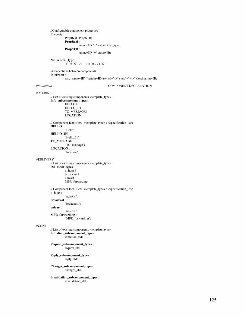
125
//Configurable component properties
Property :
PropReal | PropSTR;
PropReal :
name=ID "=" value=Real_type;
PropSTR :
name=ID "=" value=ID;
Native Real_type :
"('-')? ('0'..'9')+ (('.') ('0'..'9')+)?";
//Connections between components
Interconn :
msg_name=ID":"sender=ID(async?="->"|sync?="<->")destination=ID;
////////////////// COMPONENT DECLARATION
// MADINI
// List of existing components <template_type>
Info_subcomponent_types :
HELLO |
HELLO_1H |
TC_MESSAGE |
LOCATION;
// Component Identifiers <template_type> : <specification_id>;
HELLO :
"Hello";
HELLO_1H :
"Hello_1h";
TC_MESSAGE :
"TC_message";
LOCATION :
"location";
//DELIVERY
// List of existing components <template_type>
Del_mech_types :
n_hops |
broadcast |
unicast |
MPR_forwarding;
// Component Identifiers <template_type> : <specification_id>;
n_hops :
"n_hops";
broadcast :
"broadcast";
unicast :
"unicast";
MPR_forwarding :
"MPR_forwarding";
//CONI
// List of existing components <template_type>
Initiation_subcomponent_types :
initiation_std;
Request_subcomponent_types :
request_std;
Reply_subcomponent_types :
reply_std;
Changes_subcomponent_types :
changes_std;
Invalidation_subcomponent_types :
invalidation_std;
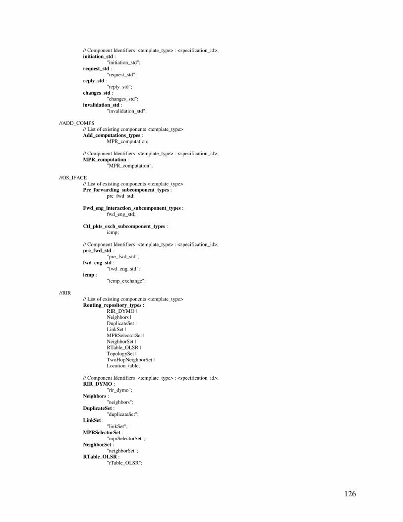
126
// Component Identifiers <template_type> : <specification_id>;
initiation_std :
"initiation_std";
request_std :
"request_std";
reply_std :
"reply_std";
changes_std :
"changes_std";
invalidation_std :
"invalidation_std";
//ADD_COMPS
// List of existing components <template_type>
Add_computations_types :
MPR_computation;
// Component Identifiers <template_type> : <specification_id>;
MPR_computation :
"MPR_computation";
//OS_IFACE
// List of existing components <template_type>
Pre_forwarding_subcomponent_types :
pre_fwd_std;
Fwd_eng_interaction_subcomponent_types :
fwd_eng_std;
Ctl_pkts_exch_subcomponent_types :
icmp;
// Component Identifiers <template_type> : <specification_id>;
pre_fwd_std :
"pre_fwd_std";
fwd_eng_std :
"fwd_eng_std";
icmp :
"icmp_exchange";
//RIR
// List of existing components <template_type>
Routing_repository_types :
RIR_DYMO |
Neighbors |
DuplicateSet |
LinkSet |
MPRSelectorSet |
NeighborSet |
RTable_OLSR |
TopologySet |
TwoHopNeighborSet |
Location_table;
// Component Identifiers <template_type> : <specification_id>;
RIR_DYMO :
"rir_dymo";
Neighbors :
"neighbors";
DuplicateSet :
"duplicateSet";
LinkSet :
"linkSet";
MPRSelectorSet :
"mprSelectorSet";
NeighborSet :
"neighborSet";
RTable_OLSR :
"rTable_OLSR";
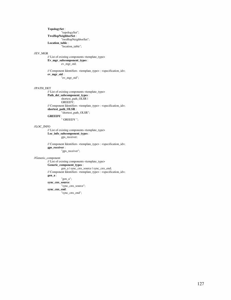
127
TopologySet :
"topologySet";
TwoHopNeighborSet :
"twoHopNeighborSet";
Location_table :
"location_table";
//EV_MGR
// List of existing components <template_type>
Ev_mgr_subcomponent_types :
ev_mgr_std;
// Component Identifiers <template_type> : <specification_id>;
ev_mgr_std :
"ev_mgr_std";
//PATH_DET
// List of existing components <template_type>
Path_det_subcomponent_types :
shortest_path_OLSR |
GREEDY;
// Component Identifiers <template_type> : <specification_id>;
shortest_path_OLSR :
"shortest_path_OLSR";
GREEDY:
" GREEDY ";
//LOC_INFO
// List of existing components <template_type>
Loc_info_subcomponent_types :
gps_receiver;
// Component Identifiers <template_type> : <specification_id>;
gps_receiver :
"gps_receiver";
//Generic_component
// List of existing components <template_type>
Generic_component_types :
gen_a | sync_cnx_source | sync_cnx_end;
// Component Identifiers <template_type> : <specification_id>;
gen_a :
"gen_a";
sync_cnx_source:
"sync_cnx_source";
sync_cnx_end:
"sync_cnx_end";
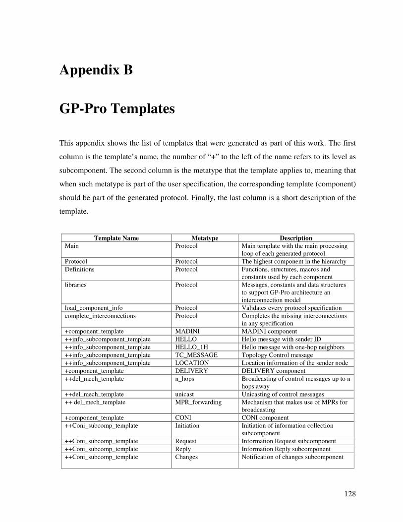
128
Appendix B
GP-Pro Templates
This appendix shows the list of templates that were generated as part of this work. The first
column is the template’s name, the number of “+” to the left of the name refers to its level as
subcomponent. The second column is the metatype that the template applies to, meaning that
when such metatype is part of the user specification, the corresponding template (component)
should be part of the generated protocol. Finally, the last column is a short description of the
template.
Template Name Metatype Description
Main Protocol Main template with the main processing
loop of each generated protocol.
Protocol Protocol The highest component in the hierarchy
Definitions Protocol Functions, structures, macros and
constants used by each component
libraries Protocol Messages, constants and data structures
to support GP-Pro architecture an
interconnection model
load_component_info Protocol Validates every protocol specification
complete_interconnections Protocol Completes the missing interconnections
in any specification
+component_template MADINI MADINI component
++info_subcomponent_template HELLO Hello message with sender ID
++info_subcomponent_template HELLO_1H Hello message with one-hop neighbors
++info_subcomponent_template TC_MESSAGE Topology Control message
++info_subcomponent_template LOCATION Location information of the sender node
+component_template DELIVERY DELIVERY component
++del_mech_template n_hops Broadcasting of control messages up to n
hops away
++del_mech_template unicast Unicasting of control messages
++ del_mech_template MPR_forwarding Mechanism that makes use of MPRs for
broadcasting
+component_template CONI CONI component
++Coni_subcomp_template Initiation Initiation of information collection
subcomponent
++Coni_subcomp_template Request Information Request subcomponent
++Coni_subcomp_template Reply Information Reply subcomponent
++Coni_subcomp_template Changes Notification of changes subcomponent
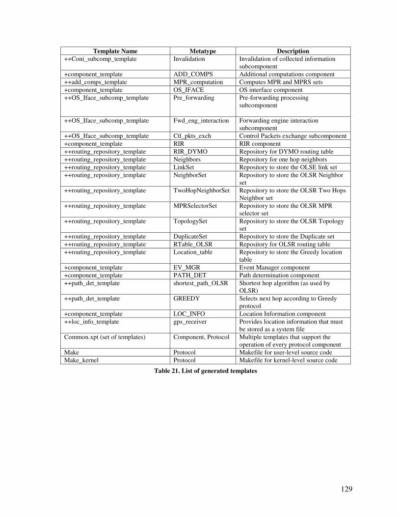
129
Template Name Metatype Description
++Coni_subcomp_template Invalidation Invalidation of collected information
subcomponent
+component_template ADD_COMPS Additional computations component
++add_comps_template MPR_computation Computes MPR and MPRS sets
+component_template OS_IFACE OS interface component
++OS_Iface_subcomp_template Pre_forwarding Pre-forwarding processing
subcomponent
++OS_Iface_subcomp_template Fwd_eng_interaction Forwarding engine interaction
subcomponent
++OS_Iface_subcomp_template Ctl_pkts_exch Control Packets exchange subcomponent
+component_template RIR RIR component
++routing_repository_template RIR_DYMO Repository for DYMO routing table
++routing_repository_template Neighbors Repository for one hop neighbors
++routing_repository_template LinkSet Repository to store the OLSE link set
++routing_repository_template NeighborSet Repository to store the OLSR Neighbor
set
++routing_repository_template TwoHopNeighborSet Repository to store the OLSR Two Hops
Neighbor set
++routing_repository_template MPRSelectorSet Repository to store the OLSR MPR
selector set
++routing_repository_template TopologySet Repository to store the OLSR Topology
set
++routing_repository_template DuplicateSet Repository to store the Duplicate set
++routing_repository_template RTable_OLSR Repository for OLSR routing table
++routing_repository_template Location_table Repository to store the Greedy location
table
+component_template EV_MGR Event Manager component
+component_template PATH_DET Path determination component
++path_det_template shortest_path_OLSR Shortest hop algorithm (as used by
OLSR)
++path_det_template GREEDY Selects next hop according to Greedy
protocol
+component_template LOC_INFO Location Information component
++loc_info_template gps_receiver Provides location information that must
be stored as a system file
Common.xpt (set of templates) Component, Protocol Multiple templates that support the
operation of every protocol component
Make Protocol Makefile for user-level source code
Make_kernel Protocol Makefile for kernel-level source code
Table 21. List of generated templates
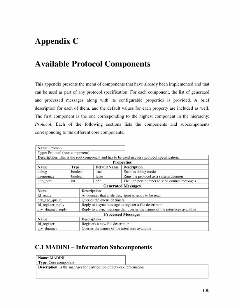
130
Appendix C
Available Protocol Components
This appendix presents the menu of components that have already been implemented and that
can be used as part of any protocol specification. For each component, the list of generated
and processed messages along with its configurable properties is provided. A brief
description for each of them, and the default values for each property are included as well.
The first component is the one corresponding to the highest component in the hierarchy:
Protocol. Each of the following sections lists the components and subcomponents
corresponding to the different core components.
Name: Protocol
Type: Protocol (root component)
Description: This is the root component and has to be used in every protocol specification.
Properties Name Type Default Value Description
debug boolean true Enables debug mode
daemonize boolean false Runs the protocol as a system daemon
udp_port int 653 The udp port number to send control messages
Generated Messages Name Description
fd_ready Announces that a file descriptor is ready to be read
qry_age_queue Queries the queue of timers
fd_register_reply Reply to a sync message to register a file descriptor
qry_ifnames_reply Reply to a sync message that queries the names of the interfaces available
Processed Messages Name Description
fd_register Registers a new file descriptor
qry_ifnames Queries the names of the interfaces available
C.1 MADINI – Information Subcomponents
Name: MADINI
Type: Core component
Description: Is the manager for distribution of network information
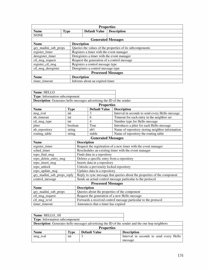
131
Properties Name Type Default Value Description
NONE
Generated Messages Name Description
qry_madini_sub_props Queries the values of the properties of its subcomponents
register_timer Registers a timer with the event manager
deregister_timer Deregisters a timer with the event manager
ctl_msg_request Request the generation of a control message
register_ctl_msg Registers a control message type
ctl_msg_deregister Deregisters a control message type
Processed Messages Name Description
timer_timeout Informs about an expired timer
Name: HELLO
Type: Information subcomponent
Description: Generates hello messages advertising the ID of the sender
Properties Name Type Default Value Description
msg_ival int 3 Interval in seconds to send every Hello message
nb_timeout int 6 Timeout for each entry in the neighbor set
ctl_msg_type int 4 Number type for Hello message
jitter boolean True Introduces a jitter for each Hello message
nb_repository string nb1 Name of repository storing neighbor information
routing_table string rtable Name of repository the routing table
Generated Messages Name Description
register_timer Request the registration of a new timer with the event manager
sched_timer Reschedules an existing timer with the event manager
repo_find_msg Finds data in a repository
repo_delete_entry_msg Deletes a specific entry from a repository
repo_insert_msg Inserts data in a repository
repo_unlock Unlocks a previously locked repository
repo_update_msg Updates data in a repository
qry_madini_sub_props_reply Reply to sync message that queries about the properties of the component
control_message Sends an actual control message particular to the protocol
Processed Messages Name Description
qry_madini_sub_props Queries about the properties of the component
ctl_msg_request Request the generation of a new Hello message
ctl_msg_rcvd Forwards a received control message particular to the protocol
timer_timeout Announces that a timer has expired
Name: HELLO_1H
Type: Information subcomponent
Description: Generates hello messages advertising the ID of the sender and the one hop neighbors
Properties Name Type Default Value Description
msg_ival int 3 Interval in seconds to send every Hello
message
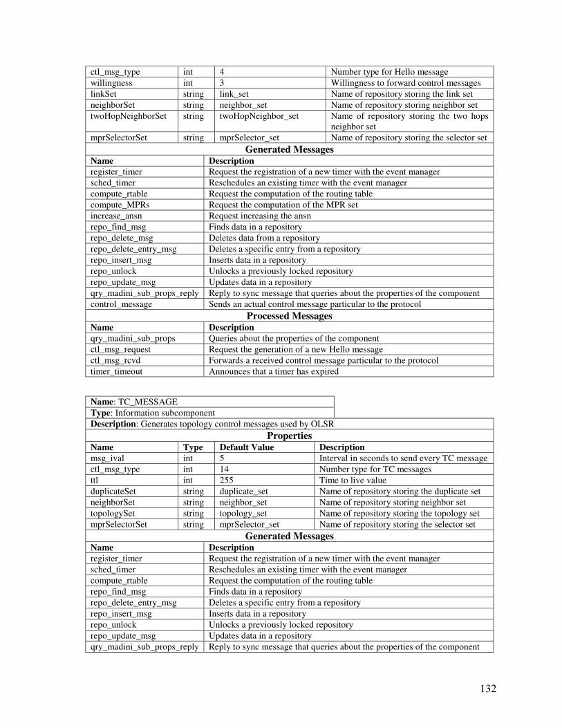
132
ctl_msg_type int 4 Number type for Hello message
willingness int 3 Willingness to forward control messages
linkSet string link_set Name of repository storing the link set
neighborSet string neighbor_set Name of repository storing neighbor set
twoHopNeighborSet string twoHopNeighbor_set Name of repository storing the two hops
neighbor set
mprSelectorSet string mprSelector_set Name of repository storing the selector set
Generated Messages Name Description
register_timer Request the registration of a new timer with the event manager
sched_timer Reschedules an existing timer with the event manager
compute_rtable Request the computation of the routing table
compute_MPRs Request the computation of the MPR set
increase_ansn Request increasing the ansn
repo_find_msg Finds data in a repository
repo_delete_msg Deletes data from a repository
repo_delete_entry_msg Deletes a specific entry from a repository
repo_insert_msg Inserts data in a repository
repo_unlock Unlocks a previously locked repository
repo_update_msg Updates data in a repository
qry_madini_sub_props_reply Reply to sync message that queries about the properties of the component
control_message Sends an actual control message particular to the protocol
Processed Messages Name Description
qry_madini_sub_props Queries about the properties of the component
ctl_msg_request Request the generation of a new Hello message
ctl_msg_rcvd Forwards a received control message particular to the protocol
timer_timeout Announces that a timer has expired
Name: TC_MESSAGE
Type: Information subcomponent
Description: Generates topology control messages used by OLSR
Properties Name Type Default Value Description
msg_ival int 5 Interval in seconds to send every TC message
ctl_msg_type int 14 Number type for TC messages
ttl int 255 Time to live value
duplicateSet string duplicate_set Name of repository storing the duplicate set
neighborSet string neighbor_set Name of repository storing neighbor set
topologySet string topology_set Name of repository storing the topology set
mprSelectorSet string mprSelector_set Name of repository storing the selector set
Generated Messages Name Description
register_timer Request the registration of a new timer with the event manager
sched_timer Reschedules an existing timer with the event manager
compute_rtable Request the computation of the routing table
repo_find_msg Finds data in a repository
repo_delete_entry_msg Deletes a specific entry from a repository
repo_insert_msg Inserts data in a repository
repo_unlock Unlocks a previously locked repository
repo_update_msg Updates data in a repository
qry_madini_sub_props_reply Reply to sync message that queries about the properties of the component
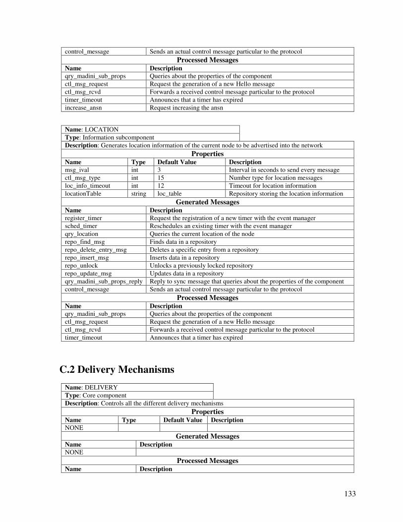
133
control_message Sends an actual control message particular to the protocol
Processed Messages Name Description
qry_madini_sub_props Queries about the properties of the component
ctl_msg_request Request the generation of a new Hello message
ctl_msg_rcvd Forwards a received control message particular to the protocol
timer_timeout Announces that a timer has expired
increase_ansn Request increasing the ansn
Name: LOCATION
Type: Information subcomponent
Description: Generates location information of the current node to be advertised into the network
Properties Name Type Default Value Description
msg_ival int 3 Interval in seconds to send every message
ctl_msg_type int 15 Number type for location messages
loc_info_timeout int 12 Timeout for location information
locationTable string loc_table Repository storing the location information
Generated Messages Name Description
register_timer Request the registration of a new timer with the event manager
sched_timer Reschedules an existing timer with the event manager
qry_location Queries the current location of the node
repo_find_msg Finds data in a repository
repo_delete_entry_msg Deletes a specific entry from a repository
repo_insert_msg Inserts data in a repository
repo_unlock Unlocks a previously locked repository
repo_update_msg Updates data in a repository
qry_madini_sub_props_reply Reply to sync message that queries about the properties of the component
control_message Sends an actual control message particular to the protocol
Processed Messages Name Description
qry_madini_sub_props Queries about the properties of the component
ctl_msg_request Request the generation of a new Hello message
ctl_msg_rcvd Forwards a received control message particular to the protocol
timer_timeout Announces that a timer has expired
C.2 Delivery Mechanisms
Name: DELIVERY
Type: Core component
Description: Controls all the different delivery mechanisms
Properties Name Type Default Value Description
NONE
Generated Messages Name Description
NONE
Processed Messages Name Description
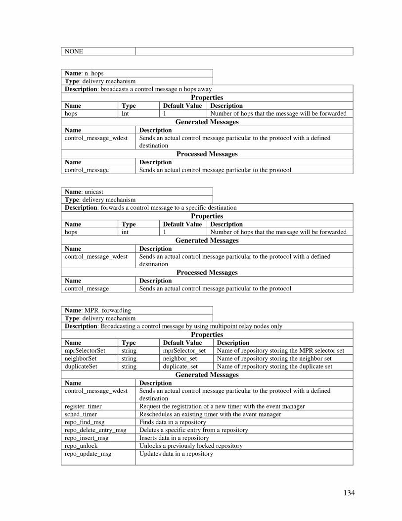
134
NONE
Name: n_hops
Type: delivery mechanism
Description: broadcasts a control message n hops away
Properties Name Type Default Value Description
hops Int 1 Number of hops that the message will be forwarded
Generated Messages Name Description
control_message_wdest Sends an actual control message particular to the protocol with a defined
destination
Processed Messages Name Description
control_message Sends an actual control message particular to the protocol
Name: unicast
Type: delivery mechanism
Description: forwards a control message to a specific destination
Properties Name Type Default Value Description
hops int 1 Number of hops that the message will be forwarded
Generated Messages Name Description
control_message_wdest Sends an actual control message particular to the protocol with a defined
destination
Processed Messages Name Description
control_message Sends an actual control message particular to the protocol
Name: MPR_forwarding
Type: delivery mechanism
Description: Broadcasting a control message by using multipoint relay nodes only
Properties Name Type Default Value Description
mprSelectorSet string mprSelector_set Name of repository storing the MPR selector set
neighborSet string neighbor_set Name of repository storing the neighbor set
duplicateSet string duplicate_set Name of repository storing the duplicate set
Generated Messages Name Description
control_message_wdest Sends an actual control message particular to the protocol with a defined
destination
register_timer Request the registration of a new timer with the event manager
sched_timer Reschedules an existing timer with the event manager
repo_find_msg Finds data in a repository
repo_delete_entry_msg Deletes a specific entry from a repository
repo_insert_msg Inserts data in a repository
repo_unlock Unlocks a previously locked repository
repo_update_msg
Updates data in a repository
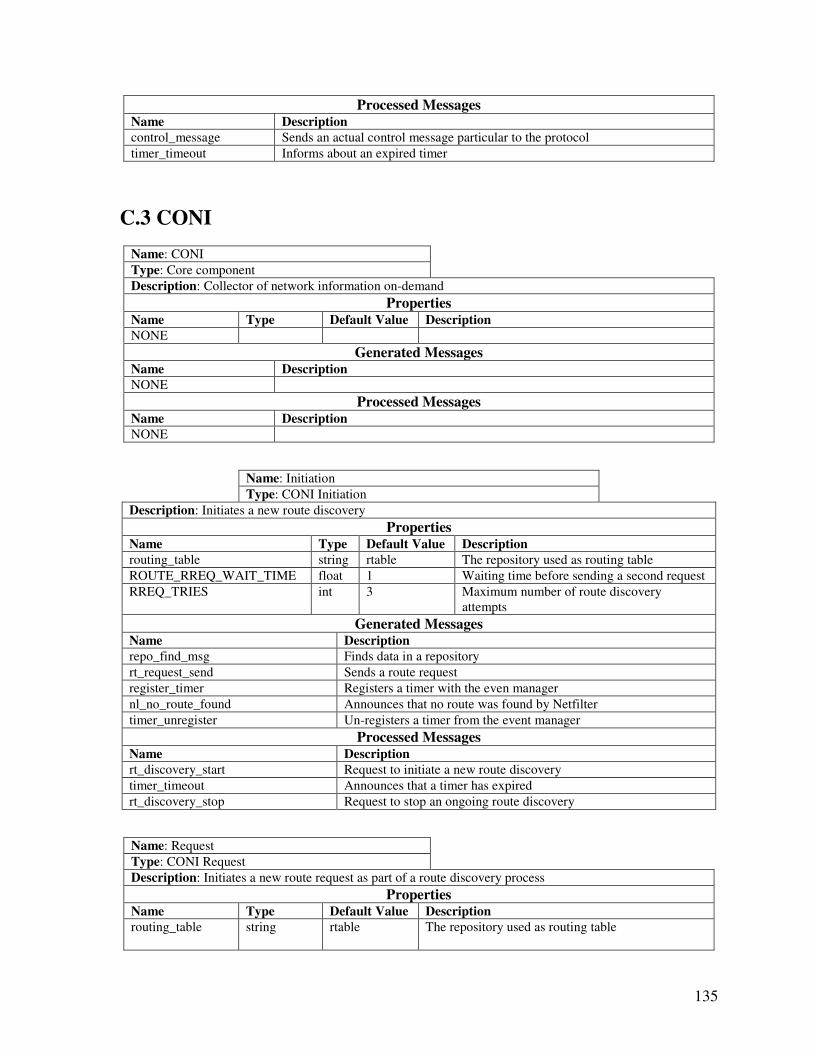
135
Processed Messages Name Description
control_message Sends an actual control message particular to the protocol
timer_timeout Informs about an expired timer
C.3 CONI
Name: CONI
Type: Core component
Description: Collector of network information on-demand
Properties Name Type Default Value Description
NONE
Generated Messages Name Description
NONE
Processed Messages Name Description
NONE
Name: Initiation
Type: CONI Initiation
Description: Initiates a new route discovery
Properties Name Type Default Value Description
routing_table string rtable The repository used as routing table
ROUTE_RREQ_WAIT_TIME float 1 Waiting time before sending a second request
RREQ_TRIES int 3 Maximum number of route discovery
attempts
Generated Messages Name Description
repo_find_msg Finds data in a repository
rt_request_send Sends a route request
register_timer Registers a timer with the even manager
nl_no_route_found Announces that no route was found by Netfilter
timer_unregister Un-registers a timer from the event manager
Processed Messages Name Description
rt_discovery_start Request to initiate a new route discovery
timer_timeout Announces that a timer has expired
rt_discovery_stop Request to stop an ongoing route discovery
Name: Request
Type: CONI Request
Description: Initiates a new route request as part of a route discovery process
Properties Name Type Default Value Description
routing_table
string rtable The repository used as routing table
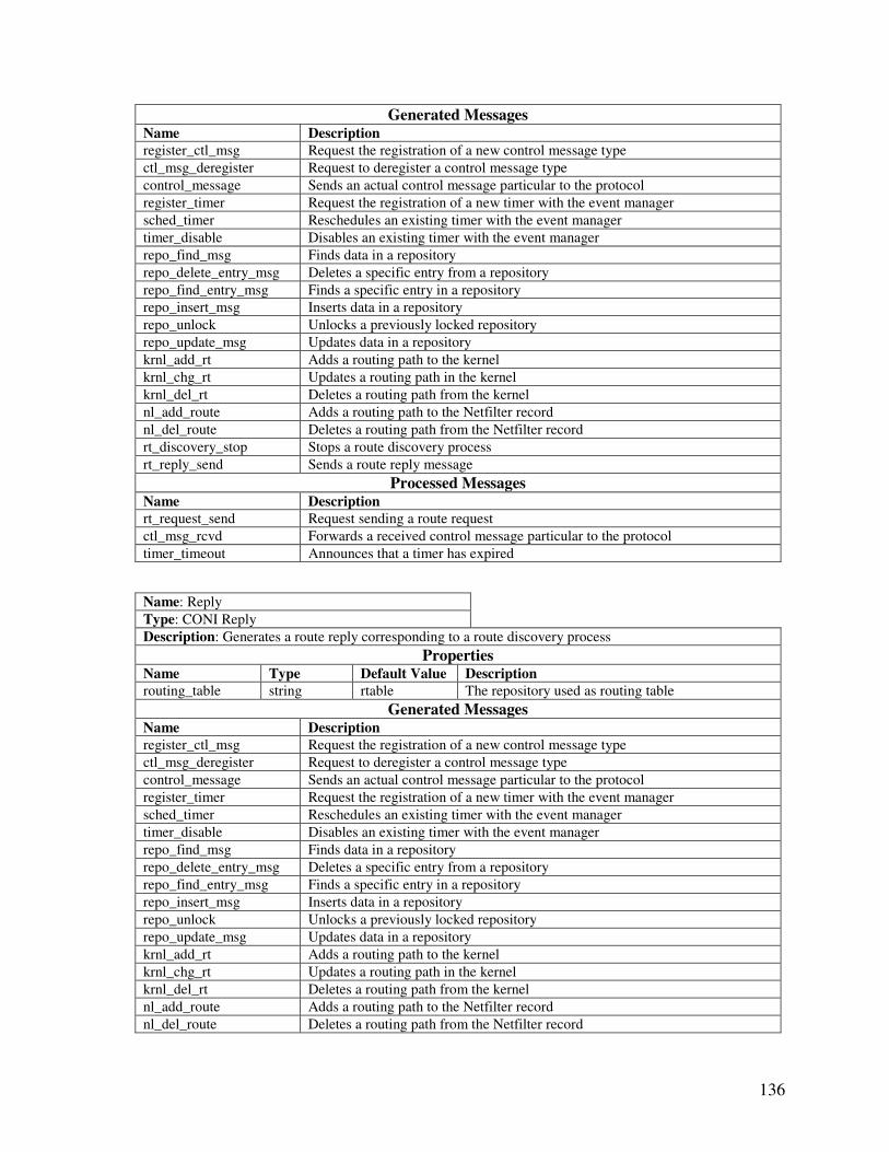
136
Generated Messages Name Description
register_ctl_msg Request the registration of a new control message type
ctl_msg_deregister Request to deregister a control message type
control_message Sends an actual control message particular to the protocol
register_timer Request the registration of a new timer with the event manager
sched_timer Reschedules an existing timer with the event manager
timer_disable Disables an existing timer with the event manager
repo_find_msg Finds data in a repository
repo_delete_entry_msg Deletes a specific entry from a repository
repo_find_entry_msg Finds a specific entry in a repository
repo_insert_msg Inserts data in a repository
repo_unlock Unlocks a previously locked repository
repo_update_msg Updates data in a repository
krnl_add_rt Adds a routing path to the kernel
krnl_chg_rt Updates a routing path in the kernel
krnl_del_rt Deletes a routing path from the kernel
nl_add_route Adds a routing path to the Netfilter record
nl_del_route Deletes a routing path from the Netfilter record
rt_discovery_stop Stops a route discovery process
rt_reply_send Sends a route reply message
Processed Messages Name Description
rt_request_send Request sending a route request
ctl_msg_rcvd Forwards a received control message particular to the protocol
timer_timeout Announces that a timer has expired
Name: Reply
Type: CONI Reply
Description: Generates a route reply corresponding to a route discovery process
Properties Name Type Default Value Description
routing_table string rtable The repository used as routing table
Generated Messages Name Description
register_ctl_msg Request the registration of a new control message type
ctl_msg_deregister Request to deregister a control message type
control_message Sends an actual control message particular to the protocol
register_timer Request the registration of a new timer with the event manager
sched_timer Reschedules an existing timer with the event manager
timer_disable Disables an existing timer with the event manager
repo_find_msg Finds data in a repository
repo_delete_entry_msg Deletes a specific entry from a repository
repo_find_entry_msg Finds a specific entry in a repository
repo_insert_msg Inserts data in a repository
repo_unlock Unlocks a previously locked repository
repo_update_msg Updates data in a repository
krnl_add_rt Adds a routing path to the kernel
krnl_chg_rt Updates a routing path in the kernel
krnl_del_rt Deletes a routing path from the kernel
nl_add_route Adds a routing path to the Netfilter record
nl_del_route Deletes a routing path from the Netfilter record
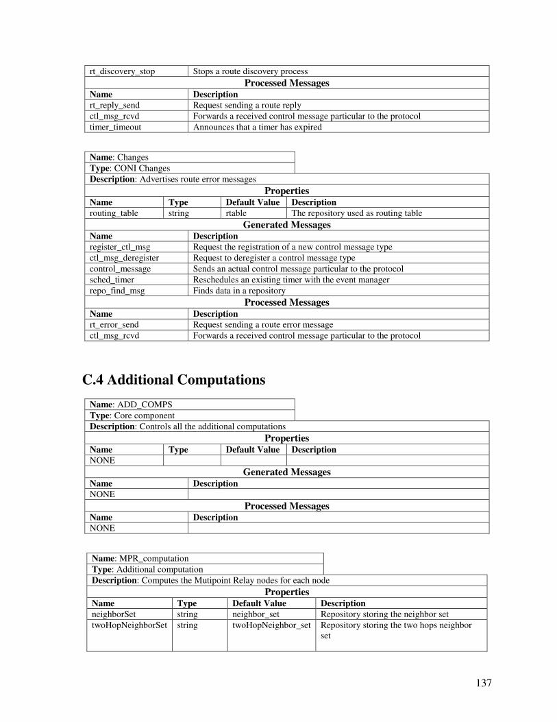
137
rt_discovery_stop Stops a route discovery process
Processed Messages Name Description
rt_reply_send Request sending a route reply
ctl_msg_rcvd Forwards a received control message particular to the protocol
timer_timeout Announces that a timer has expired
Name: Changes
Type: CONI Changes
Description: Advertises route error messages
Properties Name Type Default Value Description
routing_table string rtable The repository used as routing table
Generated Messages Name Description
register_ctl_msg Request the registration of a new control message type
ctl_msg_deregister Request to deregister a control message type
control_message Sends an actual control message particular to the protocol
sched_timer Reschedules an existing timer with the event manager
repo_find_msg Finds data in a repository
Processed Messages Name Description
rt_error_send Request sending a route error message
ctl_msg_rcvd Forwards a received control message particular to the protocol
C.4 Additional Computations
Name: ADD_COMPS
Type: Core component
Description: Controls all the additional computations
Properties Name Type Default Value Description
NONE
Generated Messages Name Description
NONE
Processed Messages Name Description
NONE
Name: MPR_computation
Type: Additional computation
Description: Computes the Mutipoint Relay nodes for each node
Properties Name Type Default Value Description
neighborSet string neighbor_set Repository storing the neighbor set
twoHopNeighborSet string twoHopNeighbor_set Repository storing the two hops neighbor
set
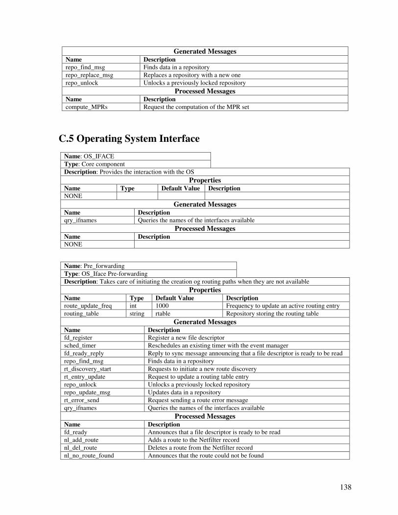
138
Generated Messages Name Description
repo_find_msg Finds data in a repository
repo_replace_msg Replaces a repository with a new one
repo_unlock Unlocks a previously locked repository
Processed Messages Name Description
compute_MPRs Request the computation of the MPR set
C.5 Operating System Interface
Name: OS_IFACE
Type: Core component
Description: Provides the interaction with the OS
Properties Name Type Default Value Description
NONE
Generated Messages Name Description
qry_ifnames Queries the names of the interfaces available
Processed Messages Name Description
NONE
Name: Pre_forwarding
Type: OS_Iface Pre-forwarding
Description: Takes care of initiating the creation og routing paths when they are not available
Properties Name Type Default Value Description
route_update_freq int 1000 Frequency to update an active routing entry
routing_table string rtable Repository storing the routing table
Generated Messages Name Description
fd_register Register a new file descriptor
sched_timer Reschedules an existing timer with the event manager
fd_ready_reply Reply to sync message announcing that a file descriptor is ready to be read
repo_find_msg Finds data in a repository
rt_discovery_start Requests to initiate a new route discovery
rt_entry_update Request to update a routing table entry
repo_unlock Unlocks a previously locked repository
repo_update_msg Updates data in a repository
rt_error_send Request sending a route error message
qry_ifnames Queries the names of the interfaces available
Processed Messages Name Description
fd_ready Announces that a file descriptor is ready to be read
nl_add_route Adds a route to the Netfilter record
nl_del_route Deletes a route from the Netfilter record
nl_no_route_found Announces that the route could not be found
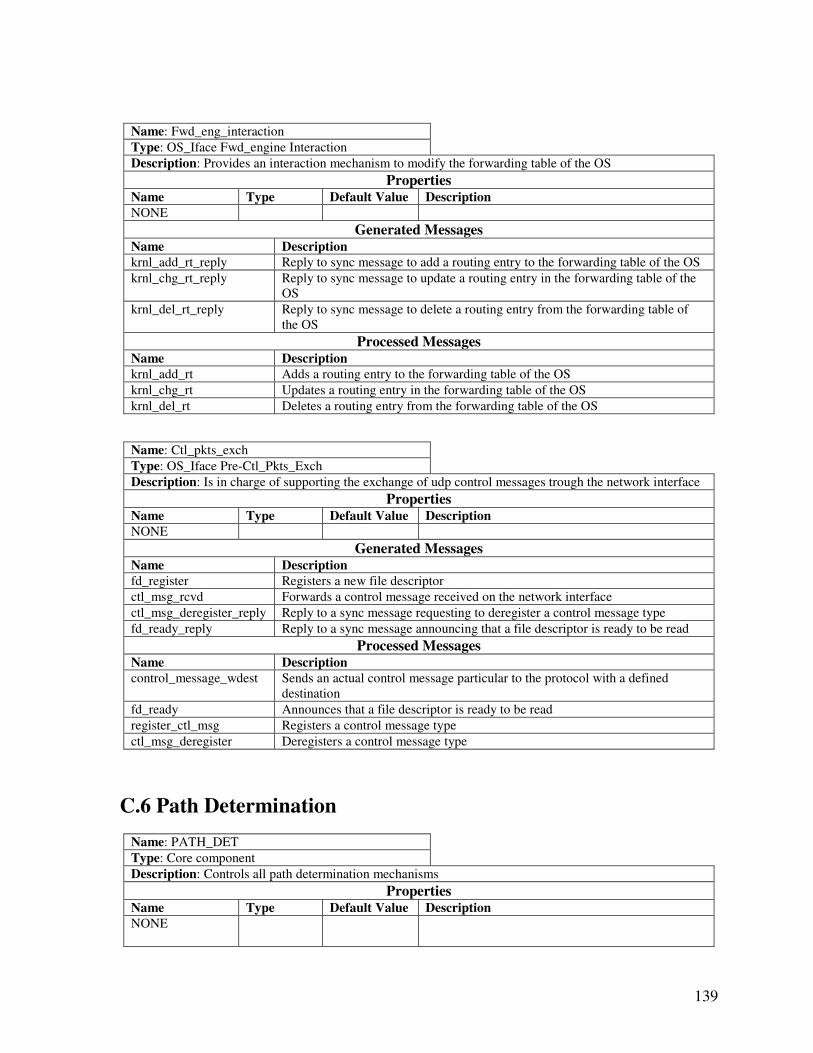
139
Name: Fwd_eng_interaction
Type: OS_Iface Fwd_engine Interaction
Description: Provides an interaction mechanism to modify the forwarding table of the OS
Properties Name Type Default Value Description
NONE
Generated Messages Name Description
krnl_add_rt_reply Reply to sync message to add a routing entry to the forwarding table of the OS
krnl_chg_rt_reply Reply to sync message to update a routing entry in the forwarding table of the
OS
krnl_del_rt_reply Reply to sync message to delete a routing entry from the forwarding table of
the OS
Processed Messages Name Description
krnl_add_rt Adds a routing entry to the forwarding table of the OS
krnl_chg_rt Updates a routing entry in the forwarding table of the OS
krnl_del_rt Deletes a routing entry from the forwarding table of the OS
Name: Ctl_pkts_exch
Type: OS_Iface Pre-Ctl_Pkts_Exch
Description: Is in charge of supporting the exchange of udp control messages trough the network interface
Properties Name Type Default Value Description
NONE
Generated Messages Name Description
fd_register Registers a new file descriptor
ctl_msg_rcvd Forwards a control message received on the network interface
ctl_msg_deregister_reply Reply to a sync message requesting to deregister a control message type
fd_ready_reply Reply to a sync message announcing that a file descriptor is ready to be read
Processed Messages Name Description
control_message_wdest Sends an actual control message particular to the protocol with a defined
destination
fd_ready Announces that a file descriptor is ready to be read
register_ctl_msg Registers a control message type
ctl_msg_deregister Deregisters a control message type
C.6 Path Determination
Name: PATH_DET
Type: Core component
Description: Controls all path determination mechanisms
Properties Name Type Default Value Description
NONE
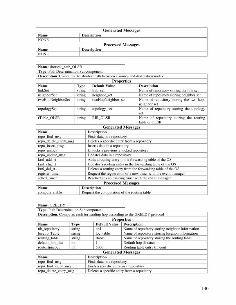
140
Generated Messages Name Description
NONE
Processed Messages Name Description
NONE
Name: shortest_path_OLSR
Type: Path Determination Subcomponent
Description: Computes the shortest path between a source and destination nodes
Properties Name Type Default Value Description
linkSet string link_set Name of repository storing the link set
neighborSet string neighbor_set Name of repository storing neighbor set
twoHopNeighborSet string twoHopNeighbor_set Name of repository storing the two hops
neighbor set
topologySet string topology_set Name of repository storing the topology
set
rTable_OLSR string RIR_OLSR Name of repository storing the routing
table of OLSR
Generated Messages Name Description
repo_find_msg Finds data in a repository
repo_delete_entry_msg Deletes a specific entry from a repository
repo_insert_msg Inserts data in a repository
repo_unlock Unlocks a previously locked repository
repo_update_msg Updates data in a repository
krnl_add_rt Adds a routing entry to the forwarding table of the OS
krnl_chg_rt Updates a routing entry in the forwarding table of the OS
krnl_del_rt Deletes a routing entry from the forwarding table of the OS
register_timer Request the registration of a new timer with the event manager
sched_timer Reschedules an existing timer with the event manager
Processed Messages Name Description
compute_rtable Request the computation of the routing table
Name: GREEDY
Type: Path Determination Subcomponent
Description: Computes each forwarding hop according to the GREEDY protocol
Properties Name Type Default Value Description
nb_repository string nb1 Name of repository storing neighbor information
locationTable string loc_table Name of repository storing location information
routing_table string rtable Name of repository storing the routing table
default_hop_dst int 1 Default hop distance
route_timeout int 5000 Routing table entry timeout
Generated Messages Name Description
repo_find_msg Finds data in a repository
repo_find_entry_msg Finds a specific entry in a repository
repo_delete_entry_msg Deletes a specific entry from a repository
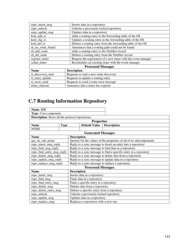
141
repo_insert_msg Inserts data in a repository
repo_unlock Unlocks a previously locked repository
repo_update_msg Updates data in a repository
krnl_add_rt Adds a routing entry to the forwarding table of the OS
krnl_chg_rt Updates a routing entry in the forwarding table of the OS
krnl_del_rt Deletes a routing entry from the forwarding table of the OS
nl_no_route_found Announces that a routing path could not be found
nl_add_route Adds a routing entry to the Netfilter record
nl_del_route Deletes a routing entry from the Netfilter record
register_timer Request the registration of a new timer with the event manager
sched_timer Reschedules an existing timer with the event manager
Processed Messages Name Description
rt_discovery_start Requests to start a new route discovery
rt_entry_update Requests to update a routing entry
rt_error_send Requests to send a route error message
timer_timeout Announce that a timer has expired
C.7 Routing Information Repository
Name: RIR
Type: Core component
Description: Hosts all the protocol repositories
Properties Name Type Default Value Description
NONE
Generated Messages Name Description
qry_rir_sub_props Queries for the values of the properties of all of its subcomponents
repo_insert_msg_reply Reply to a sync message to insert an entry into a repository
repo_find_msg_reply Reply to a sync message to find data in a repository
repo_find_entry_msg_reply Reply to a sync message to find a specific entry in a repository
repo_delete_msg_reply Reply to a sync message to delete data from a repository
repo_update_msg_reply Reply to a sync message to update data in a repository
repo_replace_msg_reply Reply to a sync message to replace a repository
Processed Messages Name Description
repo_insert_msg Inserts data in a repository
repo_find_msg Finds data in a repository
repo_find_entry_msg Finds a specific entry in a repository
repo_delete_msg Deletes data from a repository
repo_delete_entry_msg Deletes a specific entry from a repository
repo_unlock Unlocks a previously locked repository
repo_update_msg Updates data in a repository
repo_replace_msg Replaces a repository with a new one
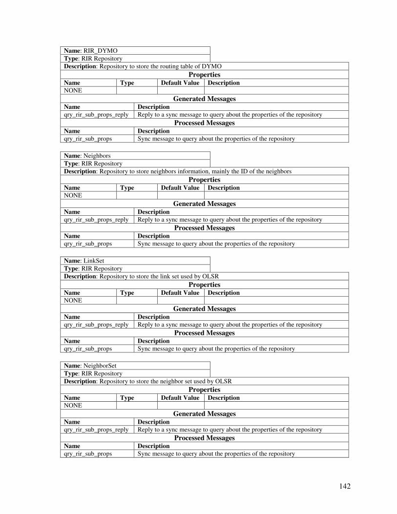
142
Name: RIR_DYMO
Type: RIR Repository
Description: Repository to store the routing table of DYMO
Properties Name Type Default Value Description
NONE
Generated Messages Name Description
qry_rir_sub_props_reply Reply to a sync message to query about the properties of the repository
Processed Messages Name Description
qry_rir_sub_props Sync message to query about the properties of the repository
Name: Neighbors
Type: RIR Repository
Description: Repository to store neighbors information, mainly the ID of the neighbors
Properties Name Type Default Value Description
NONE
Generated Messages Name Description
qry_rir_sub_props_reply Reply to a sync message to query about the properties of the repository
Processed Messages Name Description
qry_rir_sub_props Sync message to query about the properties of the repository
Name: LinkSet
Type: RIR Repository
Description: Repository to store the link set used by OLSR
Properties Name Type Default Value Description
NONE
Generated Messages Name Description
qry_rir_sub_props_reply Reply to a sync message to query about the properties of the repository
Processed Messages Name Description
qry_rir_sub_props Sync message to query about the properties of the repository
Name: NeighborSet
Type: RIR Repository
Description: Repository to store the neighbor set used by OLSR
Properties Name Type Default Value Description
NONE
Generated Messages Name Description
qry_rir_sub_props_reply Reply to a sync message to query about the properties of the repository
Processed Messages Name Description
qry_rir_sub_props Sync message to query about the properties of the repository
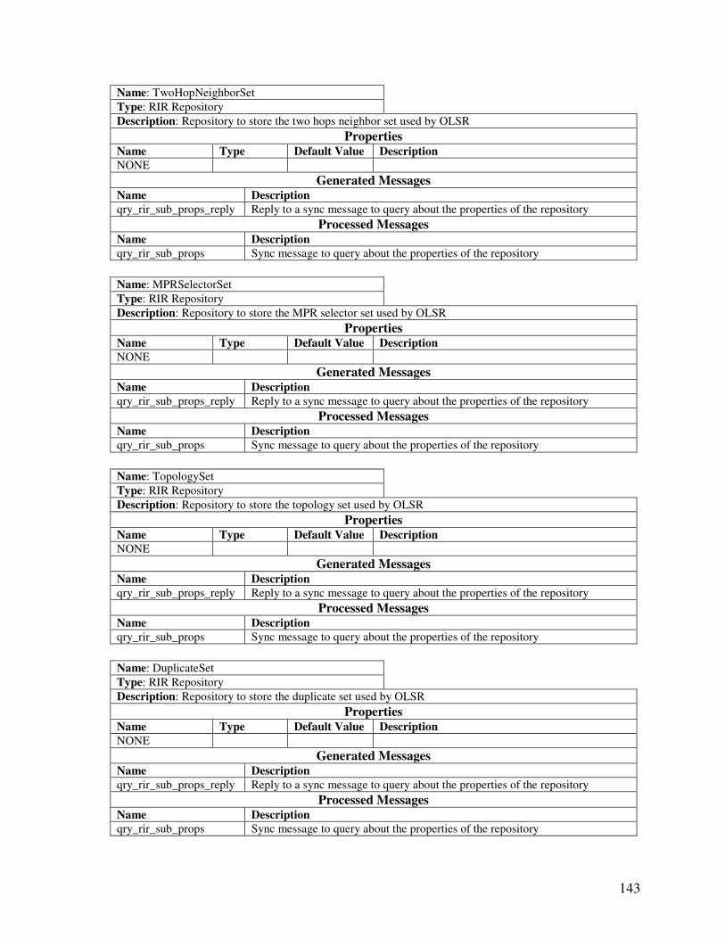
143
Name: TwoHopNeighborSet
Type: RIR Repository
Description: Repository to store the two hops neighbor set used by OLSR
Properties Name Type Default Value Description
NONE
Generated Messages Name Description
qry_rir_sub_props_reply Reply to a sync message to query about the properties of the repository
Processed Messages Name Description
qry_rir_sub_props Sync message to query about the properties of the repository
Name: MPRSelectorSet
Type: RIR Repository
Description: Repository to store the MPR selector set used by OLSR
Properties Name Type Default Value Description
NONE
Generated Messages Name Description
qry_rir_sub_props_reply Reply to a sync message to query about the properties of the repository
Processed Messages Name Description
qry_rir_sub_props Sync message to query about the properties of the repository
Name: TopologySet
Type: RIR Repository
Description: Repository to store the topology set used by OLSR
Properties Name Type Default Value Description
NONE
Generated Messages Name Description
qry_rir_sub_props_reply Reply to a sync message to query about the properties of the repository
Processed Messages Name Description
qry_rir_sub_props Sync message to query about the properties of the repository
Name: DuplicateSet
Type: RIR Repository
Description: Repository to store the duplicate set used by OLSR
Properties Name Type Default Value Description
NONE
Generated Messages Name Description
qry_rir_sub_props_reply Reply to a sync message to query about the properties of the repository
Processed Messages Name Description
qry_rir_sub_props Sync message to query about the properties of the repository
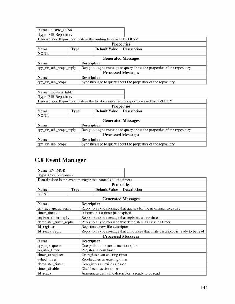
144
Name: RTable_OLSR
Type: RIR Repository
Description: Repository to store the routing table used by OLSR
Properties Name Type Default Value Description
NONE
Generated Messages Name Description
qry_rir_sub_props_reply Reply to a sync message to query about the properties of the repository
Processed Messages Name Description
qry_rir_sub_props Sync message to query about the properties of the repository
Name: Location_table
Type: RIR Repository
Description: Repository to store the location information repository used by GREEDY
Properties Name Type Default Value Description
NONE
Generated Messages Name Description
qry_rir_sub_props_reply Reply to a sync message to query about the properties of the repository
Processed Messages Name Description
qry_rir_sub_props Sync message to query about the properties of the repository
C.8 Event Manager
Name: EV_MGR
Type: Core component
Description: Is the event manager that controls all the timers
Properties Name Type Default Value Description
NONE
Generated Messages Name Description
qry_age_queue_reply Reply to a sync message that queries for the next timer to expire
timer_timeout Informs that a timer just expired
register_timer_reply Reply to a sync message that registers a new timer
deregister_timer_reply Reply to a sync message that deregisters an existing timer
fd_register Registers a new file descriptor
fd_ready_reply Reply to a sync message that announces that a file descriptor is ready to be read
Processed Messages Name Description
qry_age_queue Query about the next timer to expire
register_timer Registers a new timer
timer_unregister Un-registers an existing timer
sched_timer Reschedules an existing timer
deregister_timer Deregisters an existing timer
timer_disable Disables an active timer
fd_ready Announces that a file descriptor is ready to be read
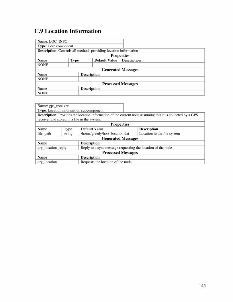
145
C.9 Location Information
Name: LOC_INFO
Type: Core component
Description: Controls all methods providing location information
Properties Name Type Default Value Description
NONE
Generated Messages Name Description
NONE
Processed Messages Name Description
NONE
Name: gps_receiver
Type: Location information subcomponent
Description: Provides the location information of the current node assuming that it is collected by a GPS
receiver and stored in a file in the system.
Properties Name Type Default Value Description
file_path string /home/greedy/host_location.dat Location in the file system
Generated Messages Name Description
qry_location_reply Reply to a sync message requesting the location of the node
Processed Messages Name Description
qry_location Requests the location of the node
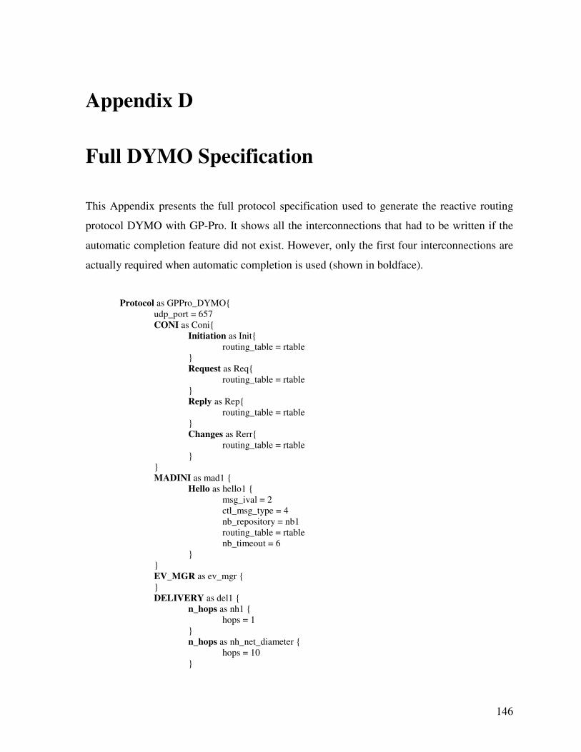
146
Appendix D
Full DYMO Specification
This Appendix presents the full protocol specification used to generate the reactive routing
protocol DYMO with GP-Pro. It shows all the interconnections that had to be written if the
automatic completion feature did not exist. However, only the first four interconnections are
actually required when automatic completion is used (shown in boldface).
Protocol as GPPro_DYMO{
udp_port = 657
CONI as Coni{
Initiation as Init{
routing_table = rtable
}
Request as Req{
routing_table = rtable
}
Reply as Rep{
routing_table = rtable
}
Changes as Rerr{
routing_table = rtable
}
}
MADINI as mad1 {
Hello as hello1 {
msg_ival = 2
ctl_msg_type = 4
nb_repository = nb1
routing_table = rtable
nb_timeout = 6
}
}
EV_MGR as ev_mgr {
}
DELIVERY as del1 {
n_hops as nh1 {
hops = 1
}
n_hops as nh_net_diameter {
hops = 10
}
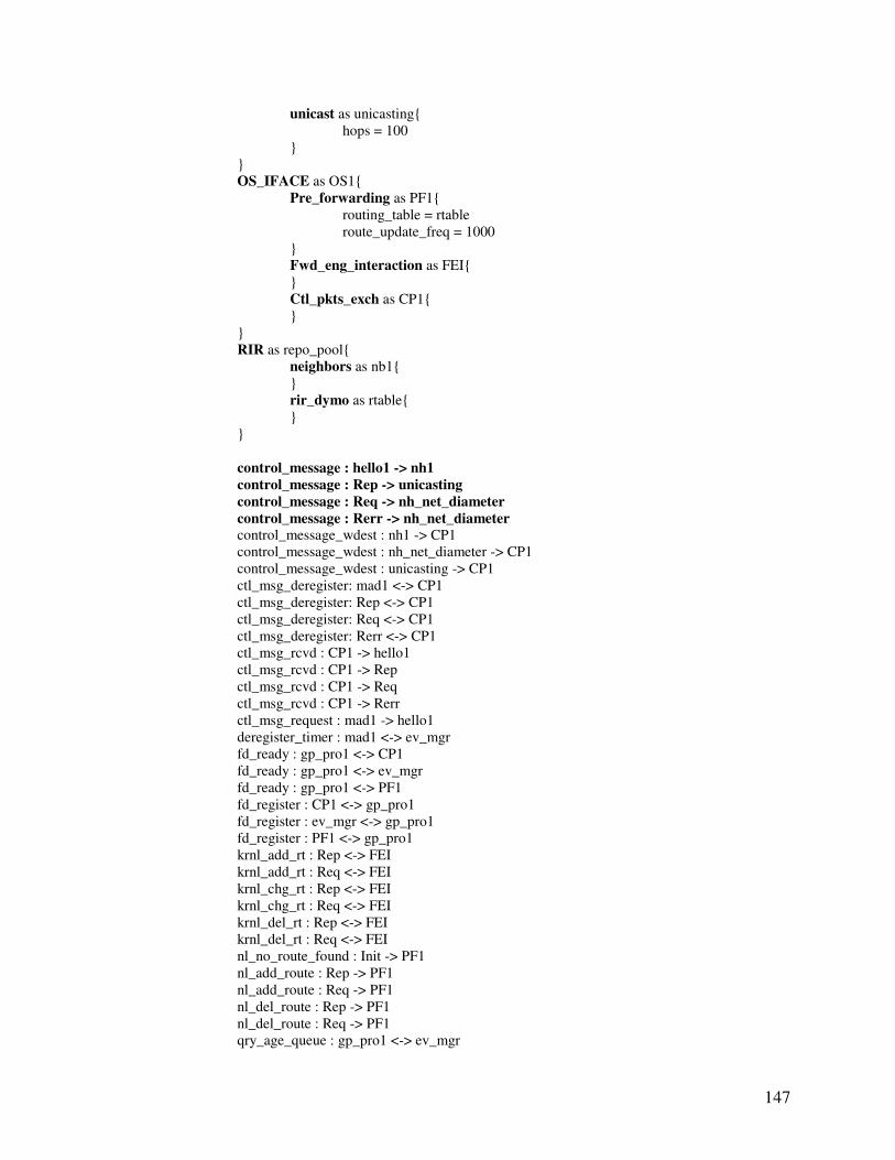
147
unicast as unicasting{
hops = 100
}
}
OS_IFACE as OS1{
Pre_forwarding as PF1{
routing_table = rtable
route_update_freq = 1000
}
Fwd_eng_interaction as FEI{
}
Ctl_pkts_exch as CP1{
}
}
RIR as repo_pool{
neighbors as nb1{
}
rir_dymo as rtable{
}
}
control_message : hello1 -> nh1
control_message : Rep -> unicasting
control_message : Req -> nh_net_diameter
control_message : Rerr -> nh_net_diameter
control_message_wdest : nh1 -> CP1
control_message_wdest : nh_net_diameter -> CP1
control_message_wdest : unicasting -> CP1
ctl_msg_deregister: mad1 <-> CP1
ctl_msg_deregister: Rep <-> CP1
ctl_msg_deregister: Req <-> CP1
ctl_msg_deregister: Rerr <-> CP1
ctl_msg_rcvd : CP1 -> hello1
ctl_msg_rcvd : CP1 -> Rep
ctl_msg_rcvd : CP1 -> Req
ctl_msg_rcvd : CP1 -> Rerr
ctl_msg_request : mad1 -> hello1
deregister_timer : mad1 <-> ev_mgr
fd_ready : gp_pro1 <-> CP1
fd_ready : gp_pro1 <-> ev_mgr
fd_ready : gp_pro1 <-> PF1
fd_register : CP1 <-> gp_pro1
fd_register : ev_mgr <-> gp_pro1
fd_register : PF1 <-> gp_pro1
krnl_add_rt : Rep <-> FEI
krnl_add_rt : Req <-> FEI
krnl_chg_rt : Rep <-> FEI
krnl_chg_rt : Req <-> FEI
krnl_del_rt : Rep <-> FEI
krnl_del_rt : Req <-> FEI
nl_no_route_found : Init -> PF1
nl_add_route : Rep -> PF1
nl_add_route : Req -> PF1
nl_del_route : Rep -> PF1
nl_del_route : Req -> PF1
qry_age_queue : gp_pro1 <-> ev_mgr

148
qry_madini_sub_props : mad1 <-> hello1
qry_rir_sub_props : repo_pool <-> nb1
qry_rir_sub_props : repo_pool <-> rtable
register_ctl_msg : mad1 -> CP1
register_ctl_msg : Rep -> CP1
register_ctl_msg : Req -> CP1
register_ctl_msg : Rerr -> CP1
register_timer : hello1 <-> ev_mgr
register_timer : Init <-> ev_mgr
register_timer : mad1 <-> ev_mgr
register_timer : Rep <-> ev_mgr
register_timer : Req <-> ev_mgr
repo_delete_entry_msg : hello1 -> repo_pool
repo_delete_entry_msg : Rep -> repo_pool
repo_delete_entry_msg : Req -> repo_pool
repo_find_entry_msg : Rep <-> repo_pool
repo_find_entry_msg : Req <-> repo_pool
repo_find_msg : hello1 <-> repo_pool
repo_find_msg : Init <-> repo_pool
repo_find_msg : PF1 <-> repo_pool
repo_find_msg : Rep <-> repo_pool
repo_find_msg : Req <-> repo_pool
repo_find_msg : Rerr <-> repo_pool
repo_insert_msg : hello1 <-> repo_pool
repo_insert_msg : Rep <-> repo_pool
repo_insert_msg : Req <-> repo_pool
repo_unlock : hello1 -> repo_pool
repo_unlock : PF1 -> repo_pool
repo_unlock : Rep -> repo_pool
repo_unlock : Req -> repo_pool
repo_update_msg : hello1 <-> repo_pool
repo_update_msg : PF1 <-> repo_pool
repo_update_msg : Rep <-> repo_pool
repo_update_msg : Req <-> repo_pool
rt_discovery_start : PF1 -> Init
rt_discovery_stop : Rep -> Init
rt_discovery_stop : Req -> Init
rt_error_send : PF1 -> Rerr
rt_reply_send : Req -> Rep
rt_request_send : Init -> Req
sched_timer : hello1 -> ev_mgr
sched_timer : PF1 -> ev_mgr
sched_timer : Rep -> ev_mgr
sched_timer : Req -> ev_mgr
sched_timer : Rerr -> ev_mgr
sync_initialize : gp_pro1 <-> Coni
sync_initialize : gp_pro1 <-> mad1
sync_initialize : gp_pro1 <-> ev_mgr
sync_initialize : gp_pro1 <-> del1
sync_initialize : gp_pro1 <-> OS1
sync_initialize : gp_pro1 <-> repo_pool
sync_initialize : repo_pool <-> nb1
sync_initialize : repo_pool <-> rtable
sync_initialize : del1 <-> nh1
sync_initialize : del1 <-> nh_net_diameter
sync_initialize : del1 <-> unicasting
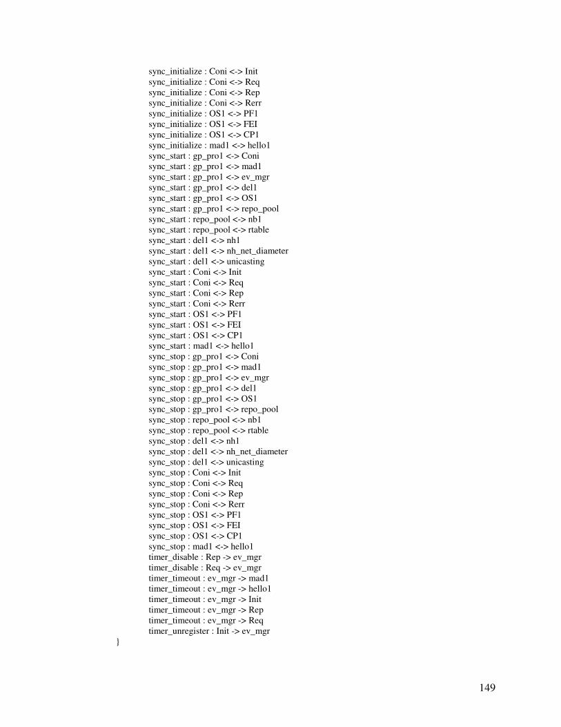
149
sync_initialize : Coni <-> Init
sync_initialize : Coni <-> Req
sync_initialize : Coni <-> Rep
sync_initialize : Coni <-> Rerr
sync_initialize : OS1 <-> PF1
sync_initialize : OS1 <-> FEI
sync_initialize : OS1 <-> CP1
sync_initialize : mad1 <-> hello1
sync_start : gp_pro1 <-> Coni
sync_start : gp_pro1 <-> mad1
sync_start : gp_pro1 <-> ev_mgr
sync_start : gp_pro1 <-> del1
sync_start : gp_pro1 <-> OS1
sync_start : gp_pro1 <-> repo_pool
sync_start : repo_pool <-> nb1
sync_start : repo_pool <-> rtable
sync_start : del1 <-> nh1
sync_start : del1 <-> nh_net_diameter
sync_start : del1 <-> unicasting
sync_start : Coni <-> Init
sync_start : Coni <-> Req
sync_start : Coni <-> Rep
sync_start : Coni <-> Rerr
sync_start : OS1 <-> PF1
sync_start : OS1 <-> FEI
sync_start : OS1 <-> CP1
sync_start : mad1 <-> hello1
sync_stop : gp_pro1 <-> Coni
sync_stop : gp_pro1 <-> mad1
sync_stop : gp_pro1 <-> ev_mgr
sync_stop : gp_pro1 <-> del1
sync_stop : gp_pro1 <-> OS1
sync_stop : gp_pro1 <-> repo_pool
sync_stop : repo_pool <-> nb1
sync_stop : repo_pool <-> rtable
sync_stop : del1 <-> nh1
sync_stop : del1 <-> nh_net_diameter
sync_stop : del1 <-> unicasting
sync_stop : Coni <-> Init
sync_stop : Coni <-> Req
sync_stop : Coni <-> Rep
sync_stop : Coni <-> Rerr
sync_stop : OS1 <-> PF1
sync_stop : OS1 <-> FEI
sync_stop : OS1 <-> CP1
sync_stop : mad1 <-> hello1
timer_disable : Rep -> ev_mgr
timer_disable : Req -> ev_mgr
timer_timeout : ev_mgr -> mad1
timer_timeout : ev_mgr -> hello1
timer_timeout : ev_mgr -> Init
timer_timeout : ev_mgr -> Rep
timer_timeout : ev_mgr -> Req
timer_unregister : Init -> ev_mgr
}
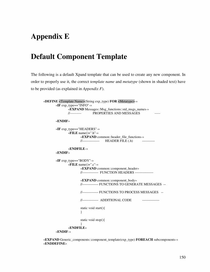
150
Appendix E
Default Component Template
The following is a default Xpand template that can be used to create any new component. In
order to properly use it, the correct template name and metatype (shown in shaded text) have
to be provided (as explained in Appendix F).
«DEFINE <Template Name>(String exp_type) FOR <Metatype>-»
«IF exp_type=="INFO"-»
«EXPAND Messages::Msg_functions::std_msgs_names-»
//---------- PROPERTIES AND MESSAGES -----
«ENDIF»
«IF exp_type=="HEADERS"-»
«FILE name()+".h"-»
«EXPAND common::header_file_functions-»
//--------------- HEADER FILE (.h) -----------
«ENDFILE-»
«ENDIF»
«IF exp_type=="BODY"-»
«FILE name()+".c"-»
«EXPAND common::component_header»
//-------------- FUNCTION HEADERS ----------------
«EXPAND common::component_body»
//-------------- FUNCTIONS TO GENERATE MESSAGES --
//-------------- FUNCTIONS TO PROCESS MESSAGES --
//-------------- ADDITIONAL CODE ---------------
static void start(){
}
static void stop(){
}
«ENDFILE»
«ENDIF-»
«EXPAND Generic_components::component_template(exp_type) FOREACH subcomponents-»
«ENDDEFINE»
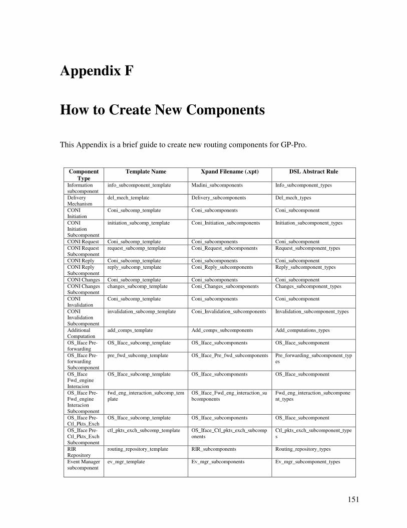
151
Appendix F
How to Create New Components
This Appendix is a brief guide to create new routing components for GP-Pro.
Component
Type
Template Name Xpand Filename (.xpt) DSL Abstract Rule
Information
subcomponent
info_subcomponent_template Madini_subcomponents Info_subcomponent_types
Delivery
Mechanism
del_mech_template Delivery_subcomponents Del_mech_types
CONI
Initiation
Coni_subcomp_template Coni_subcomponents Coni_subcomponent
CONI
Initiation
Subcomponent
initiation_subcomp_template Coni_Initiation_subcomponents Initiation_subcomponent_types
CONI Request Coni_subcomp_template Coni_subcomponents Coni_subcomponent
CONI Request
Subcomponent
request_subcomp_template Coni_Request_subcomponents Request_subcomponent_types
CONI Reply Coni_subcomp_template Coni_subcomponents Coni_subcomponent
CONI Reply
Subcomponent
reply_subcomp_template Coni_Reply_subcomponents Reply_subcomponent_types
CONI Changes Coni_subcomp_template Coni_subcomponents Coni_subcomponent
CONI Changes
Subcomponent
changes_subcomp_template Coni_Changes_subcomponents Changes_subcomponent_types
CONI
Invalidation
Coni_subcomp_template Coni_subcomponents Coni_subcomponent
CONI
Invalidation
Subcomponent
invalidation_subcomp_template Coni_Invalidation_subcomponents Invalidation_subcomponent_types
Additional
Computation
add_comps_template Add_comps_subcomponents Add_computations_types
OS_Iface Pre-
forwarding
OS_Iface_subcomp_template OS_Iface_subcomponents OS_Iface_subcomponent
OS_Iface Pre-
forwarding
Subcomponent
pre_fwd_subcomp_template OS_Iface_Pre_fwd_subcomponents Pre_forwarding_subcomponent_typ
es
OS_Iface
Fwd_engine
Interacion
OS_Iface_subcomp_template OS_Iface_subcomponents OS_Iface_subcomponent
OS_Iface Pre-
Fwd_engine
Interacion
Subcomponent
fwd_eng_interaction_subcomp_tem
plate
OS_Iface_Fwd_eng_interaction_su
bcomponents
Fwd_eng_interaction_subcompone
nt_types
OS_Iface Pre-
Ctl_Pkts_Exch
OS_Iface_subcomp_template OS_Iface_subcomponents OS_Iface_subcomponent
OS_Iface Pre-
Ctl_Pkts_Exch
Subcomponent
ctl_pkts_exch_subcomp_template OS_Iface_Ctl_pkts_exch_subcomp
onents
Ctl_pkts_exch_subcomponent_type
s
RIR
Repository
routing_repository_template RIR_subcomponents Routing_repository_types
Event Manager
subcomponent
ev_mgr_template Ev_mgr_subcomponents Ev_mgr_subcomponent_types
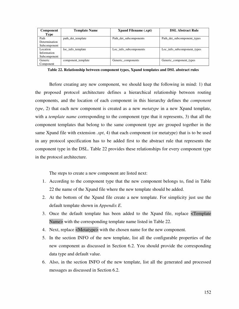
152
Component
Type
Template Name Xpand Filename (.xpt) DSL Abstract Rule
Path
Determination
Subcomponent
path_det_template Path_det_subcomponents Path_det_subcomponent_types
Location
Information
Subcomponent
loc_info_template Loc_info_subcomponents Loc_info_subcomponent_types
Generic
Component
component_template Generic_components Generic_component_types
Table 22. Relationship between component types, Xpand templates and DSL abstract rules
Before creating any new component, we should keep the following in mind: 1) that
the proposed protocol architecture defines a hierarchical relationship between routing
components, and the location of each component in this hierarchy defines the component
type, 2) that each new component is created as a new metatype in a new Xpand template,
with a template name corresponding to the component type that it represents, 3) that all the
component templates that belong to the same component type are grouped together in the
same Xpand file with extension .xpt, 4) that each component (or metatype) that is to be used
in any protocol specification has to be added first to the abstract rule that represents the
component type in the DSL. Table 22 provides these relationships for every component type
in the protocol architecture.
The steps to create a new component are listed next:
1. According to the component type that the new component belongs to, find in Table
22 the name of the Xpand file where the new template should be added.
2. At the bottom of the Xpand file create a new template. For simplicity just use the
default template shown in Appendix E.
3. Once the default template has been added to the Xpand file, replace <Template
Name> with the corresponding template name listed in Table 22.
4. Next, replace <Metatype> with the chosen name for the new component.
5. In the section INFO of the new template, list all the configurable properties of the
new component as discussed in Section 6.2. You should provide the corresponding
data type and default value.
6. Also, in the section INFO of the new template, list all the generated and processed
messages as discussed in Section 6.2.
153
7. Provide all the C code that belongs to the new component in the section BODY of the
new template. Remember that each listed property becomes a variable with the entire
component as scope.
8. Provide a function for each processed message. The name of the function should be
the name of the processed message with prefix “proc_”, as discussed in Section 6.2.
9. Use the section HEADER of the new template as you would use a .h header file when
programming in C language (e.g., to declare function headers).
10. Any function, task or statement that is to be executed when the component starts to
operate, should be included in the function start() listed in the section BODY of the
new template.
11. Any function, task or statement that is to be executed before the component stops
operation, should be included in the function stop() listed in the section BODY of the
new template.
12. The metatype of the new component should be added to the DSL as part of the
abstract rule that corresponds to the component type (the DSL is contained in the file
GPPro_icm.xtxt). To do so, before the semicolon that defines the end of the rule, the
following syntax should be added: | <Metatype>. That is, the vertical bar plus one
white space and the name of the metatype.
13. Right after the abstract rule, a new rule should be added to the DSL by using the
following syntax: <Metatype> : “<name_in_specfication>”;. That is the name of
the metatype, white space, colon, white space, a random name to be used in any
specification to make reference to the new component (written between quotation
marks) and a semicolon.
14. Once the DSL is modified as described in steps 12 and 13, the DSL should be re-
generated by using oAW inside Eclipse. Then, the DSL should be exported as a
deployable plug-in inside Eclipse.
15. Finally, restart Eclipse and the new component could be used as part of any
specification.
NOTE: A wizard to create new components will be integrated in the application hosting the
GUI. This wizard should also automate steps 12 to 14.
154
Appendix G
GP-Pro Logo
Figure 25. GP-Pro logo
GP-Pro aims to generate routing protocols by assembling existing components addressing
different features of routing protocols. Each of those components can be assembled by one of
more subcomponents of finer granularity. Figure 25 shows the GP-Pro logo, which resembles
the previous description, a set of components of different shapes and sizes providing different
functionalities (different colors), which might contain additional subcomponents.
155
Bibliography
[1] C. Perkins, E. Belding-Royer, and S. Das, "Ad hoc on-demand distance vector (AODV)
routing," IETF Mobile Ad Hoc Networks Working Group, IETF RFC 3561, July 2003.
[2] T. Clausen and P. Jacquet, "Optimized link state routing protocol (OLSR)," IETF Mobile
Ad Hoc Networks Working Group, IETF RFC 3626, October 2003.
[3] R. G. Ogier, M. Lewis, and F. L. Templin, "Topology dissemination based on reverse-
path forwarding (TBPRF)," IETF Mobile Ad Hoc Networks Working Group, IETF RFC
3684, February 2004.
[4] D. Johnson, Y. Hu, and D. Maltz, "The dynamic source routing protocol (DSR) for
mobile ad hoc networks for IPv4," IETF Mobile Ad Hoc Networks Working Group, IETF
RFC 4728, February 2007.
[5] I. D. Chakeres, E. M. Royer, and C. E. Perkins, "Dynamic MANET on-demand routing
protocol," in Proceedings of the Sixty-Second Internet Engineering Task Force, 2004.
[6] Laboratoire d'informatique de l'ecole polytechnique, hipercom, "OLSRv2 development
blog," March 2007, http://olsrv2.online.fr/blog/.
[7] S. Kurkowski, T. Camp, and M. Colagrosso, "MANET simulation studies: The
incredibles," ACM's Mobile Computing and Communications Review, vol. 9, pp. 50-61,
October 2005.
[8] T. Kunz, "Implementation vs. simulation: Evaluating a MANET multicast protocol," in
Proceedings of the Global Mobile Congress 2004, 2004, pp. 129-134.
[9] F. Haq and T. Kunz, "Simulation vs. emulation: Evaluating mobile ad hoc network
routing protocols," in Proceedings of the International Workshop on Wireless Ad-hoc
Networks, 2005.
[10] E. Göktürk, "Emulating ad hoc networks: differences from simulations and emulation
specific problems," in New Trends in Computer Networks, Vol. 1, Advances in Computer
Science and Engineering Series, Ed. Imperial College Press, 2005, pp. 329-338.
156
[11] N. C. Hutchinson and L. L. Peterson, "The x-kernel: An architecture for implementing
network protocols," IEEE Transactions on Software Engineering, vol. 17, pp. 64-76, January
1991.
[12] D. C. Schmidt, "The ADAPTIVE communication environment: An object-oriented
network programming toolkit for developing communication software," in Proceedings of
the Twelfth Annual Sun Users Group Conference, 1994, pp. 214- 225.
[13] M. Barbeau and F. Bordeleau, "A protocol stack development tool using generative
programming," in Proceedings of Generative Programming and Component Engineering,
2002, pp. 93-109.
[14] K. Czarnecki and U. W. Eisenecker, "Components and generative programming," in
Proceedings of the Seventh European Software Engineering Conference, 1999, pp. 2-19.
[15] V. Kawadia, Y. Zhang, and B. Gupta, "System services for ad-hoc routing: Architecture,
implementation and experiences," in Proceedings of the First International Conference on
Mobile Systems, Applications, and Services, 2003, pp. 99-112.
[16] The Internet Engineering Task Force (IETF), "Mobile ad hoc networks working group,"
last accessed on May 2009, http://www.ietf.org/html.charters/manet-charter.html.
[17] S. Corson and J. Macker, "Mobile ad hoc networking (MANET): Routing protocol
performance issues and evaluation considerations," IETF Mobile Ad Hoc Networks Working
Group, IETF RFC 2501, January 1999.
[18] P. Mohapatra and S. Krishnamurthy, Ad Hoc Networks: Technologies and Protocols.
Boston: Springer, 2004, ISBN 0-387-22690-7.
[19] I. Stojmenovic, A. Nayak, J. Kuruvila, F. Ovalle-Martinez, and E. Villanueva-Peña,
"Physical layer impact on the design and performance of routing and broadcasting protocols
in ad hoc and sensor networks," Computer Communications, vol. 28, pp. 1138-1151, June
2005.
[20] Wikipedia, "List of ad-hoc routing protocols," last accessed on May 2009,
http://en.wikipedia.org/wiki/List_of_ad-hoc_routing_protocols.
[21] J. Moy, "OSPF version 2," IETF Mobile Ad Hoc Networks Working Group, IETF RFC
2328, April 1998.
[22] Z. Haas, J. Halpern, and L. Li, "Gossip-based ad hoc routing," in Proceedings of the
IEEE Conference on Computer Communications, 2002, pp. 1707–1716.
157
[23] E. Kohler, R. Morris, B. Chen, J. Jannotti, and M. F. Kaashoek, "The Click modular
router," ACM Transactions on Computer Systems, vol. 18, pp. 263-297, August 2000.
[24] M. Pearlman and Z. Haas, "Determining the optimal configuration for the zone routing
protocol," IEEE Journal on Selected Areas in Communications, vol. 17, pp. 1395-1414,
August 1999.
[25] C. Santivanez, R. Ramanathan, and I. Stavrakakis, "Making link-state routing scale for
ad hoc networks," in Proceedings of the ACM International Symposium on Mobile Ad Hoc
Networking and Computing, 2001, pp. 22–32.
[26] S. Basagni, I. Chlamtac, V. R. Syrotiuk, and B. A. Woodward, "A distance routing
effect algorithm for mobility (DREAM)," in Proceedings of the IEEE/ACM Annual
International Conference on Mobile Computing and Networking, 1998, pp. 76–84.
[27] Y. Ko and N. H. Vaidya, "Location-aided routing (LAR) in mobile ad hoc networks," in
Proceedings of the ACM/IEEE International Conference on Mobile Computing and
Networking, 1998, pp. 66–75.
[28] P. Bose, P. Morin, I. Stojmenovic, and J. Urrutia, "Routing with guaranteed delivery in
ad hoc wireless networks," ACM Wireless Networks, vol. 7, pp. 609-616, November 2001.
[29] L. Qin and T. Kunz, "On-demand routing in MANETs: The impact of a realistic
physical layer model," in Proceedings of the Second International Conference on Ad Hoc
Networks and Wireless, 2003, pp. 37-48.
[30] R. Draves, J. Padhye, and B. Zill, "Comparison of routing metrics for static multi-hop
wireless networks," in Proceedings of the ACM Annual Conference of the Special Interest
Group on Data Communication, 2004, pp. 133-144.
[31] D. De Couto, D. Aguayo, J. Bicket, and R. Morris, "A high-throughput path metric for
multi-hop wireless routing," in Proceedings of the ACM Annual International Conference on
Mobile Computing and Networking, 2003, pp. 134-146.
[32] I. Stojmenovic and Xu Lin, "Power-aware localized routing in wireless networks," IEEE
Transactions on Parallel and Distributed Systems, vol. 12, pp. 1122-1133, November 2001.
[33] R. Leung, J. Lio, E. Poon, C. Chan, and B. Li, "MP-DSR: A qos-aware multi-path
dynamic source routing protocol for wireless ad-hoc networks," in Proceedings of Twenty-
Sixth Annual IEEE Conference on Local Computer Networks, 2001, pp. 132-141.
158
[34] P. Sinha, R. Sivakumar, and V. Bharghavan, "CEDAR: A core-extraction distributed ad
hoc routing algorithm," in Proceedings of the IEEE Conference on Computer
Communications, 1999, pp. 1454-1465.
[35] L. Xiao, J. Wang, and K. Nahrstedt, "The enhanced ticket based routing algorithm," in
Proceedings of the IEEE International Conference on Communications, 2002, pp. 2222-
2226.
[36] M. E. Fayad and D. Schmidt, "Object-Oriented application frameworks,"
Communications of ACM, vol. 40, pp. 32-38, October 1997.
[37] J. Parssinen, "Java protocol framework," M.S. thesis, Helsinki University of
Technology, Helsinki, Finland, 1998.
[38] Netfilter Core Team, "Netfilter framework," last accessed on May 2009,
http://www.netfilter.org.
[39] M. Handley, O. Hodson, and E. Kohler, "Xorp: An open platform for network research,"
ACM Computer Communication Review, vol. 33, pp. 53-57, January 2003.
[40] N. Pryce and S. Crane, "A model of interaction in concurrent and distributed systems,"
in Proceedings of the Second International Workshop on Development and Evolution of
Software Architectures for Product Families, 1998, pp. 26-27.
[41] M. Jung and E. W. Biersack, "A component-based architecture for software
communication systems," in Proceedings of the IEEE International Conference on the
Engineering of Computer-Based Systems, 2000, pp. 36-44.
[42] Pervasive Communications Lab, University of Colorado at Boulder, "The Click DSR
router project," last accessed on May 2009, http://pecolab.colorado.edu/html/dsrClick.html.
[43] T. E. Dorum, "ClickOLSR Element Documentation," last accessed on May 2009,
http://www.olsr.org.
[44] C. E. Perkins and P. Bhagwat, "Highly dynamic destination-sequenced distance-vector
routing (DSDV) for mobile computers," in Proceedings of the ACM Annual Conference of
the Special Interest Group on Data Communication, 1993, pp. 234–244.
[45] H. Huang and J. S. Baras, "Component based routing: A new methodology for designing
routing protocols for MANET," presented at 25th Army Science Conference, Orlando, USA,
2006.
159
[46] Z. Li and M. Barbeau, "Performance of generative programming based protocol
implementation," in Proceedings of the Second Annual Conference on Communication
Networks and Services Research, 2004, pp. 113-120.
[47] M. Barbeau, "An Implementation of DSR in IPv4," March 2002,
http://www.scs.carleton.ca/~barbeau.
[48] K. Czarnecki, "Overview of generative software development," in Proceedings of
Unconventional Programming Paradigms, 2004, pp. 313-328.
[49] T. Stahl and M. Volter, Model-Driven Software Development: Technology, Engineering,
Management. West Sussex: Wiley, 2006, ISBN 0470025700.
[50] M. Volter, "OpenArchitectureWare, a flexible open source platform for model-driven
software development," presented at Eclipse Technology Exchange Workshop at the
European Conference on Object-Oriented Programming, Nantes, France, 2006.
[51] S. Perrin, E. Benoit, and L. Foulloy, "Automatic code generation based on generic
description of intelligent instrument," in Proceedings of the IEEE International Conference
on Systems, Man, and Cybernetics, 2002, pp. 569-574.
[52] I. S. Abdullah and D. A. Menasce, "Protocol specification and automatic
implementation using XML and CBSE," in Proceedings of the International Conference on
Communications, Internet and Information Technology, 2003.
[53] D. Song, "An automatic approach for building secure systems," Ph.D. dissertation,
University of California at Berkeley, Berkeley, CA, USA, 2003.
[54] S. Behnel and A. Buchmann, "Overlay networks - implementation by specification," in
Proceedings of the International Middleware Conference, 2005, pp. 401-410.
[55] B. T. Loo, J. M. Hellerstein, and I. Stoica, "Customizable routing with declarative
queries," in Proceedings of the ACM Workshop on Hot Topics in Networks, 2004.
[56] J. Allard, P. Gonin, M. Singh, and G. G. Richard III, "A user level framework for ad hoc
routing," in Proceedings of the Twenty-Seventh Annual IEEE Conference Local Computer
Networks, 2002, pp. 13-19.
[57] B. Wiberg, "Porting AODV-UU implementation to ns-2 and enabling trace-based
simulation," M.S. thesis, Uppsala University, Uppsala, Sweden, 2002.
160
[58] A. K. Saha, K. A. To, S. PalChaudhuri, S. Du, and D. B. Johnson, "Design and
performance of PRAN: A system for physical implementation of ad hoc network routing
protocols," IEEE Transactions on Mobile Computing, vol. 6, pp. 463-479, April 2007.
[59] The Virtual InterNetwork Testbed (VINT) Project Research Staff, The NS Manual
(Formerly NS Notes and Documentation), The Virtual InterNetwork Testbed (VINT) Project,
2007.
[60] F. J. Ros, "DYMOUM, DYMO implementation for real world and simulation," last
accessed on May 2009, http://masimum.dif.um.es/?Software:DYMOUM.
[61] I. Stojmenovic, "Position based routing in ad hoc networks," IEEE Communications
Magazine, vol. 40, pp. 128-134, July 2002.
[62] S. Giordano and I. Stojmenovic, "Position based ad hoc routes in ad hoc networks," in
The Handbook of Ad Hoc Wireless Networks, CRC Press, 2003, pp.1-14.
[63] D. Parnas, "On the design and development of program families," IEEE Transactions on
Software Engineering, vol. 2, pp. 1-9, March 1976.
[64] J. C. Cleaveland, Program Generators with XML and Java. New Jersey: Prentice-Hall,
2001, ISBN 0130258784.
[65] O. Wibling, J. Parrow, and A. Pears, "Automatized verification of ad hoc routing
protocols," in Proceedings of the Twenty-Fourth International Conference on Formal
Techniques for Networked and Distributed Systems of the International Federation for
Information Processing Working Group 6.1, 2004, pp. 343-358.
[66] R. de Renesse and A. Aghvami, "Formal verification of ad-hoc routing protocols using
SPIN model checker," in Proceedings of the Twelfth Mediterranean Electrotechnical
Conference, 2004, pp. 1177-1182.
[67] J. Wu, B. Wu, and I. Stojmenovic, "Power-aware broadcasting and activity scheduling
in ad hoc wireless networks using connected dominating sets," Wireless Communications
and Mobile Computing, vol. 4, pp. 425-438, June 2003.
[68] V. Park and M. S. Corson, "A highly adaptive distributed routing algorithm for mobile
wireless networks," in Proceedings of the IEEE Conference on Computer Communications,
1997, pp. 1405-1413.
161
[69] I. Stojmenovic and E. Villanueva-Peña, "A scalable quorum based location update
scheme for routing in ad hoc wireless networks," SITE, University of Ottawa, TR-99-09,
September 1999.
[70] P. E. Villanueva-Peña and T. Kunz, "GP-Pro: The generative programming protocol
generator for routing in mobile ad hoc networks," in Proceedings of the Second IEEE
Workshop on Wireless Mesh Networks, 2006, pp. 129-131.
[71] S. Efftinge, "Xtext Reference Documentation," last accessed on May 2009,
http://www.openarchitectureware.org/.
[72] E. Nordström, "Ad-hoc on-demand distance vector routing: For real world and
simulation," last accessed on May 2009, http://core.it.uu.se/core/index.php/AODV-UU.
[73] A. Tonnesen, "Implementing and extending the optimized link state routing protocol,"
M.S. thesis, University of Oslo, Oslo, Norway, 2004.
[74] S. Jarzabek, P. Basset, H. Zhang, and W. Zhang, "XVCL: XML-based variant
configuration language," in Proceedings of the International Conference on Software
Engineering, 2003, pp. 810-811.
[75] P. Bassett, Framing Software Reuse - Lessons from Real World. Upper Saddle River,
NJ: Yourdon Press, 1997, ISBN 013327859X.
[76] M. Murata, D. Lee, and M. Mani, "Taxonomy of XML schema languages using formal
language theory," in Proceedings of Extreme Markup Languages, 2001, pp. 153-166.
[77] E. Van der Vlist, "Comparing XML schema languages," last accessed on May 2009,
http://www.xml.com/pub/a/2001/12/12/schemacompare.html.
[78] E. Van der Vlist, "Relax NG, compared," last accessed on May 2009,
http://www.xml.com/pub/a/2002/01/23/relaxng.html.
[79] E. Van der Vilst, Relax NG. California: O’Reilly, 2003, ISBN 0596004214.
[80] Sun developer network, "Java API for XML processing (JAXP)," last accessed on May
2009, http://java.sun.com/webservices/jaxp/.
[81] Delta Software Technology GmbH Technical Staff, "ANGIE - An introduction," last
accessed on May 2009, http://www.d-s-t-g.com/neu/pages/pageseng/etop.htm.
[82] The Eclipse Foundation, "Eclipse: An open development platform," last accessed on
May 2009, http://www.eclipse.org/.
162
[83] S. Efftinge, "OpenArchitectureWare 4.1: Check - Validation Language," last accessed
on May 2009, http://www.openarchitectureware.org/.
[84] S. Efftinge and M. Voelter, "OpenArchitectureWare 4.1: Workflow Engine Reference,"
last accessed on May 2009, http://www.openarchitectureware.org/.
[85] S. Efftinge, "OpenArchitectureWare 4.1: Extend Language Reference," last accessed on
May 2009, http://www.openarchitectureware.org/.
[86] S. Efftinge and C. Kadura, "OpenArchitectureWare 4.1: Xpand Language Reference,"
last accessed on May 2009, http://www.openarchitectureware.org/.


![Generative Adversarial Networks (GANs) · where D is our discriminator, G is our generator, and and are their corresponding parameters. [ 2 ] E. A. Goodfellow, Ian, Generative Adversarial](https://static.fdocuments.us/doc/165x107/600a86125440d662d579d7fe/generative-adversarial-networks-gans-where-d-is-our-discriminator-g-is-our-generator.jpg)