
Government Polytechnic Muzaffarpurgpmuz.bih.nic.in/docs/em.pdf · Aim: - Calibration and Testing of...
17
1 | Page Government Polytechnic Muzaffarpur Name of the Lab: Electrical Measurement & Machine Lab Subject Code: 1620307 Experiment-03 AIM: To measure 3-phase reactive power using single phase wattmeter APPARATUS: S.NO Equipment Range Type Quantity 1 Single Phase Wattmeter 2 Three Phase inductive load AC 2 THEORY: Three phase reactive power can be measured by two wattmeter method which is universally adopted Method. The difference between higher reading wattmeter and lower wattmeter reading yields VLILsin. so, the total 3 reactive power is √3 V L I L sin Reactive power in a balance 3- load can also be calculated by using single wattmeter. In this method, the current coil of the wattmeter is connected in any on line and the pressure coils across the other two lines. Let us assume that the Current coil is connected in R phase and pressure coil is connected across ‘Y’ and ‘B’ phases. Assuming phases. Assuming phase sequence RYB and an inductive load of an angle ‘ ’ the phasor diagram for the circuits is as follows. Current through current coil = IR Voltage across pressure coil = VYB The phase angle between VYB and IR from the phasor diagram is
Transcript of Government Polytechnic Muzaffarpurgpmuz.bih.nic.in/docs/em.pdf · Aim: - Calibration and Testing of...
1 | P a g e
Government Polytechnic Muzaffarpur Name of the Lab: Electrical Measurement & Machine
Lab
Subject Code: 1620307
Experiment-03
AIM: To measure 3-phase reactive power using single phase wattmeter APPARATUS:
S.NO Equipment Range Type Quantity
1
Single Phase
Wattmeter
2
Three Phase
inductive load
AC
2
THEORY:
Three phase reactive power can be measured by two wattmeter method which is
universally adopted Method. The difference between higher reading wattmeter and lower
wattmeter reading yields VLILsin. so, the total 3 reactive power is √3 V L I L sin
Reactive power in a balance 3- load can also be calculated by using single
wattmeter. In this method, the current coil of the wattmeter is connected in any on line and
the pressure coils across the other two lines. Let us assume that the Current coil is
connected in R phase and pressure coil is connected across ‘Y’ and ‘B’ phases. Assuming
phases. Assuming phase sequence RYB and an inductive load of an angle ‘’ the phasor
diagram for the circuits is as follows.
Current through current coil = IR
Voltage across pressure coil = VYB
The phase angle between VYB and IR from the phasor diagram is

2 | P a g e
90°- Wattmeter reading is VYB IR Cos (90°-)
W = VYB IR Sin (90°-)
In terms of line current and
voltage W = VYB IR
Cos (90°-)
Items of line current and voltage
W = VL IL Sin
The total 3- reactive power is √3 VL IL Sin
CIRCUIT DIAGRAM:
PROCEDURE:
1. Connect the circuit as shown in fig.
2. Switch ‘ON’ the supply.
3. Note down the corresponding there reading and calculate 3-reactive power.
4. Now increase the load of three phase Inductive load steps and note down the
3 | P a g e
corresponding meter readings.
5. Remove the load and switch ‘off’ the supply.
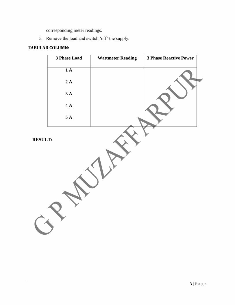
TABULAR COLUMN:
3 Phase Load Wattmeter Reading 3 Phase Reactive Power
1 A
2 A
3 A
4 A
5 A
RESULT:

1 11
Government Polytechnic Muzaffarpur Name of the Lab: Electrical Measurement & Machine
Lab
Subject Code: 1620307
Experiment-04
Aim: - Measurement of three phase reactive power using two wattmeter method.
APPARATUS:
S.NO Equipment Range Type Quantity
1
Single Phase
Wattmeter
2
2
Three Phase Resistive
Load
AC
THEORY:
Three Phase reactive power can be measured by two wattmeter method which is
universally adopted Method. The difference between higher reading wattmeter and lower
wattmeter reading yields VL*IL Sin. So, the total 3 phase reactive power is √3 VL *
ILSin
Reactive power in a balance 3- load can also be calculated by using single
wattmeter. In this method, the current coil of the wattmeter is connected in any on line and
the pressure coils across the other two lines. Let us assume that the Current coil is
connected in R phase and pressure coil is connected across ‘Y’ and ‘B’ phases. Assuming
phase sequence RYB and an inductive load of an angle ‘’ the phasor diagram for the
circuits is as follows.

2 22
Here current through current coil = IR
Voltage across pressure coil = VYB
The phase current lags the corresponding phasor voltages by an angle 𝜑
The current through wattmeter P1 is I and a voltage across its pressure coil is V1 leads
V by an angle (30 − 𝜑).
Reading of P1 wattmeter,
𝑃1 = √3 VIcos(30 − 𝜑)
The current through wattmeter P2 is I and voltages across its pressure coil is V2 lags V by an
an angle (30 + 𝜑)
Reading of P2 wattmeter,
𝑃2 = √3𝑉𝐼 cos(30 + 𝜑)
Sum of reading of two Wattmeter
𝑃1 + 𝑃2 = √3𝑉𝐼[cos(30 − 𝜑) + cos(30 + 𝜑)]
= 3𝑉𝐼 cos 𝜑 This is total power consumed by load P
P = P1 + P2
Difference of readings of twoWattmeter
𝑃1 − 𝑃2 = √3𝑉𝐼[cos(30 − 𝜑) − cos(30 + 𝜑)] 𝑃1 − 𝑃2
𝑃1 + 𝑃2
=√3𝑉𝐼 sin 𝜑
√3𝑉𝐼 cos 𝜑
Power factor
cos 𝜑 = cos tan−1𝑃1 − 𝑃2
𝑃1 + 𝑃2
3 33
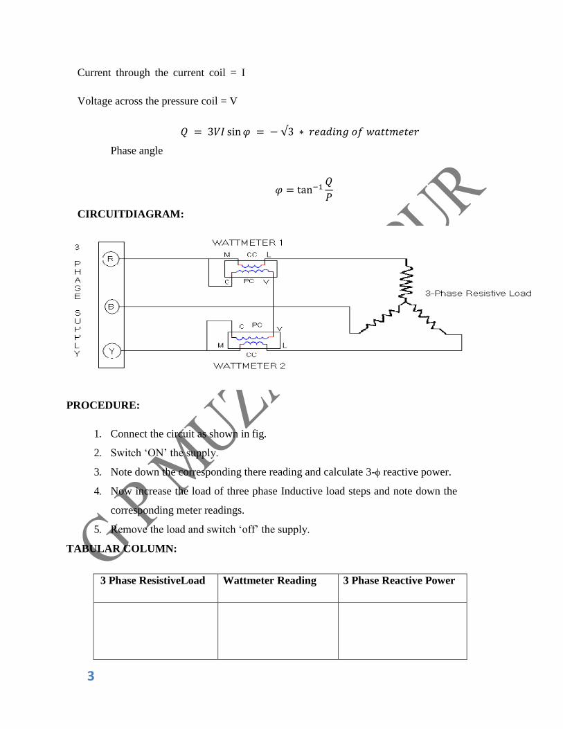
Current through the current coil = I
Voltage across the pressure coil = V
𝑄 = 3𝑉𝐼 sin 𝜑 = − √3 ∗ 𝑟𝑒𝑎𝑑𝑖𝑛𝑔 𝑜𝑓 𝑤𝑎𝑡𝑡𝑚𝑒𝑡𝑒𝑟
Phase angle
𝜑 = tan−1𝑄
𝑃
CIRCUITDIAGRAM:
PROCEDURE:
1. Connect the circuit as shown in fig.
2. Switch ‘ON’ the supply.
3. Note down the corresponding there reading and calculate 3-reactive power.
4. Now increase the load of three phase Inductive load steps and note down the
corresponding meter readings.
5. Remove the load and switch ‘off’ the supply.
TABULAR COLUMN:
3 Phase ResistiveLoad Wattmeter Reading 3 Phase Reactive Power

4 44
Results:
PRECAUTIONS:
1. Instruments used should be of proper range.
2. All the connections should be tight.
1 | P a g e
Government Polytechnic Muzaffarpur Name of the Lab: Electrical Measurement & Machine
Lab
Subject Code: 1620307-
Experiment-05
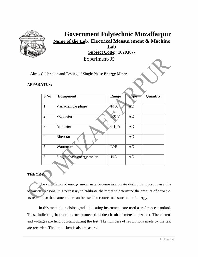
Aim: - Calibration and Testing of Single Phase Energy Meter.
APPARATUS:
S.No Equipment Range Type Quantity
1 Variac,single phase 10 A AC
2 Voltmeter 300 V AC
3 Ammeter 0-10A AC
4 Rheostat AC
5 Wattmeter LPF AC
6 Single phase energy meter 10A AC
THEORY:
The calibration of energy meter may become inaccurate during its vigorous use due
to various reasons. It is necessary to calibrate the meter to determine the amount of error i.e.
its reading so that same meter can be used for correct measurement of energy.
In this method precision grade indicating instruments are used as reference standard.
These indicating instruments are connected in the circuit of meter under test. The current
and voltages are held constant during the test. The numbers of revolutions made by the test
are recorded. The time taken is also measured.

2 | P a g e
Energy recorded by meter under test = RX / KXkWh.
Energy computed from the readings of the indicating instrument = kW × t
Where RX = number of revolutions made by disc of meter under test.
KX = number of revolutions per kWh for meter under test,
kW = power in kilowatt as computed from readings f indicating
instruments t = time in hours.
Percentage Error = (RX / KX- kW ×t) X 100 kW × t
Before conducting any of these tests on a watt hour meter its potential circuit must
be connected to the supply for one hour in order to enable the self-heating of the potential
coil to stabilize.
CIRCUIT DIAGRAM:
figure: 1
PROECEDURE:
1. Keep the Autotransformer at zeroposition.
2. Make connections as per the Circuit diagram shownbelow.
3. Switch on the 230 VAC, 50 Hz. powersupply.
4. Increase the input voltage gradually by rotating the Auto transformer in clockwise
direction.
5. Adjust the load rheostat so that sufficient current flows in the circuit. Please

3 | P a g e
note that the current should be less than4A.
6. Note down the Voltmeter, Ammeter, Wattmeter and power factor meter
readings for different Voltages as per the tabularcolumn.
7. Note down the time (by using stop watch) for rotating the disc of the Energy
Meter for 10 times. Find out the percentage error by using aboveequations.
TABULAR COLUMN
S. No. Voltag
e (V)
Current
(I)
R = No of
revolutions
of the disc
Time
(t) in
hours
Energy meter
reading in KWh=
No. revolution
(R)/meter constant
(K)
Wattmeter
Reading in
kW × t
%
Error
RESULT:

Government Polytechnic Muzaffarpur Name of the Lab: Electrical Measurement & Machine Lab
Subject Code: 1620307
Experiment-08
Aim: - Measurement of the medium resistance by using Whetstone Bridge
method.
Apparatus: - Power Supply
Resistor: - 10K_-1no,5K_-
1no,11K_-1no Unknown
resistor=100_, Pot =1K-1no. Wheat stone bridge
kit. Digital
multimeter-1no,
Patch codes.
Theory-
A very important device used in the measurement of medium resistances is the
Wheat stones bridge .It is an accurate and reliable instrument .The wheat stone
bridge is an instrument based on the principle of null indication and comparison
measurements.
The basic circuit of a wheat stone bridge is shown in figure below. It has four
resistive arms consisting of resistances P,Q,R and S together with a source of emf
and a null detector, usually a galvanometer G or other sensitive current meter is
used. The current through the galvanometer depends on the potential difference
between point b and d. The bridge is said to be balanced when there is no current
through the galvanometer or when the potential difference across the
galvanometer is zero. This occurs when the voltage from point ‘b’ to point ‘a’
equals the voltage from point d to point ‘a’ or by referring to other battery
terminal. When the voltage from point d to point c equals the voltage from point b
to point c.
For bridge balance;
I1P=I2 R ……………..
(1) I1=I3=E/P+Q
……….. (2)
I2=I4=E/R+S………… (3) E=emf of battery. Combining equation (1) and
(2);
we get;
P/P+Q=R/R+S……….

(4)
QR=PS………………. (5)
Equation (5) shows the balance condition of wheat stone bridge. If three of the
resistances are known then fourth may be determined by formula… R=S*P/Q Where R is the unknown resistance, S is called the standard arm resistor and P and
Q are called the ratio arms.
Procedure: - 1) Connect the patch cord as per the circuit diagram. 2) Note the resistance of P and Q using multimeter. 3) Adjust the resistance of P, Q, R,S
4) Switch on the power supply and adjust the resistance S such that
galvanometer shows the zero deflection.
5) Now calculate R,
R=P*S/Q
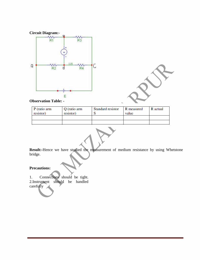
Circuit Diagram:-
Observation Table: -
Result:-Hence we have studied the measurement of medium resistance by using Whetstone
bridge.
Precautions:
1. Connections should be tight.
2.Instrument should be handled
carefully

Government Polytechnic Muzaffarpur Name of the Lab: Electrical Measurement & Machine Lab
Subject Code: 1620307
Experiment-07
Aim: - Measurement of the low resistance by using Kelvin Double bridge
method.
Apparatus: - Regulated dc supply-
1no Standard resistance coil-1no
Kelvin’s double bridge
kit Digital multimeter-
1no Patch codes.
Theory: -
Kelvin’s bridge is a modification of Whetstone Bridge and always used in
measurement of low resistance. It uses two sets of ratio arms and the four
terminal resistances for the low resistance consider the circuit as shown in
figure below. The first set of ratio P and Q. The second set of ratio arms are p
and q is used to connected to galvanometer to a point d at an approximate
potential between points m and n to eliminate the effects of connecting lead of
resistance r between the known standard resistance ‘s’ and unknown resistance
R. The ratio P/Q is made equal to p/q. Under balanced condition, there is no
current flowing through galvanometer which means voltage drop between a and
b, Eab equal to the voltage drop between a and c, Eamd.
Now
Ead=P/P+Q; Eab=I[R+S+[(p+q)r/p+q+r]] ……….. (1)
Eamd= I[R+ p/p+q[ (p+q)r/p+q+r]] ………………….
(2)
For zero deflection-
Eac=Ead [P/P+Q]I[R+S+{(p+q)r/p+q+r}]=I[R+pr/p+q+r] ……. (3) Now, If P/Q=p/q
Then equation is
R=P/Q=S
……(4)
Equation (4) is the usual working equation. For the Kelvin’s Double Bridge .It indicates the resistance of connecting lead r. It has no effect on measurement provided that the two sets of ratio arms have equal ratios. Equation (3) is useful however as it shows the error that is introduced in case the ratios are not exactly equal. It indicates that it is desirable to keep r as small as possible in order to minimize the error in case there is a difference between the ratio P/Q and p/q.
R/S=P/Q

Circuit Diagram: -
Observation Table: -
Procedure: - 1) The circuit configuration on the panel is studied.
2) Supply is switched on and increased upto5v.
3) The unknown resistance is connected as shown. 4) The value of P,Q was selected such that P/Q=p/q 5) S was adjusted for proper balance and balance value of s was balanced.
6) The value of known resistance was calculated.
Result- The observed value of unknown resistance is ……….

Precautions-
1) Check all the connections before turning ON the power supply.
2) Do not exceed the value of 5v.
3) Note the readings accurately.

[Type text] Page 7