GOODWAY MACHINE CORP. - Ron Mack€¦ · GOODWAY MACHINE CORP. SERIES GLS-150M. GLS-150Y HIGH SPEED...
20
GLS-150 High Speed CNC Turning Centers GOODWAY MACHINE CORP. SERIES GLS-150M
Transcript of GOODWAY MACHINE CORP. - Ron Mack€¦ · GOODWAY MACHINE CORP. SERIES GLS-150M. GLS-150Y HIGH SPEED...

GLS-150 High Speed CNC Turning Centers
GOODWAY MACHINE CORP.
SERIES
GLS-150M

GLS-150Y
HIGH SPEED CNC TURNING CENTERS
Packed with industry leading technology and top quality components, the Goodway GLS series
turning centers combine power, strength, and speed to bring you The Ultimate Machining
Power®. These high speed machines will easily accomplish the demanding turning applications
of today and tomorrow. Furthermore, with optional live tooling, C-axis, and Y-axis, milling, turning
applications can be completed in one single machine.
GLS Series Construction Spindle Turret Multi-Tasking
30˚ slant-bed design provides smooth chip
disposal and easier operator access.
Steel way covers and special steel wipers
molded with industrial strength rubber are
used for durability.
Fully enclosed splashguards keep chips and
coolant contained for a safe clean working
environment.
The auto lubrication system delivers
metered amounts of lubrication to the slide
ways, ball screws, and vital components.
Distribution is automatically shut o�
during idling to prevent waste.
Y-axis models perform virtually the same way as machining centers
equipped with 4th-axis rotary tables, but with the bene�t of built-in
turning capability. The X, Y, Z axes are like that of a machining center,
while the C-axis acts as the 4-axis. This con�guration replaces a turning
center and machining center equipped with 4th-axis with one machine,
thus, saving money, time, �oor space, manpower and �xture costs, while
reducing accuracy lost by eliminating the part from being moved to
another machine.
Y-axis
C-axis
X-axis
Z-axis
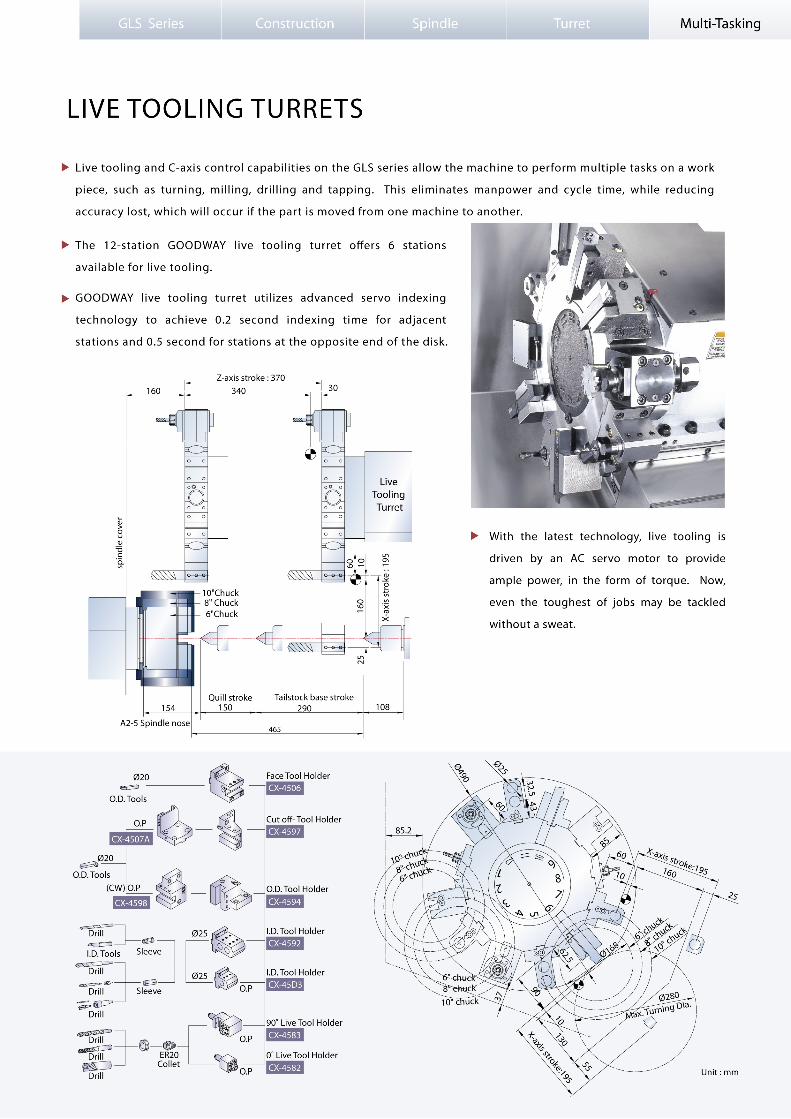
Live tooling and C-axis control capabilities on the GLS series allow the
machine to perform multiple tasks on a work piece, such as turning,
milling, drilling and tapping. This can save manpower and reduce cycle
time, while reducing accuracy lost, which will occur if the part is moved
from one machine to another.
( GLS-150Y model shown with optional accessories )
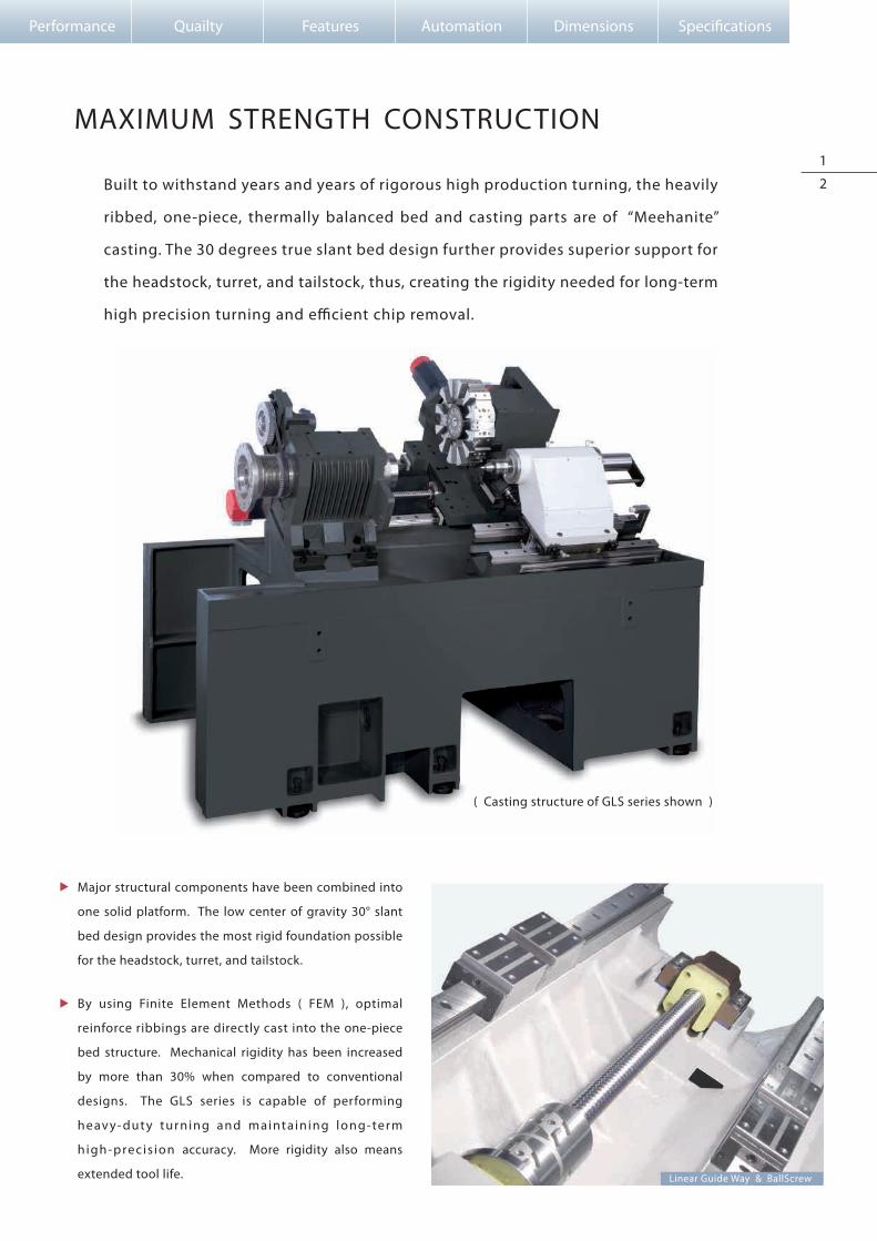
Built to withstand years and years of rigorous high production turning, the heavily
ribbed, one-piece, thermally balanced bed and casting parts are of “Meehanite”
casting. The 30 degrees true slant bed design further provides superior support for
the headstock, turret, and tailstock, thus, creating the rigidity needed for long-term
high precision turning and e�cient chip removal.
MAXIMUM STRENGTH CONSTRUCTION
Major structural components have been combined into
one solid platform. The low center of gravity 30° slant
bed design provides the most rigid foundation possible
for the headstock, turret, and tailstock.
By using Finite Element Methods ( FEM ), optimal
reinforce ribbings are directly cast into the one-piece
bed structure. Mechanical rigidity has been increased
by more than 30% when compared to conventional
designs. The GLS series is capable of performing
heav y- dut y turning and maintaining long-term
high-precis ion accuracy. More rigidity also means
extended tool life.
1
2
( Casting structure of GLS series shown )
Linear Guide Way & BallScrew
Performance Quailty Features Automation Dimensions Speci�cations

GH
E
I
FDCBM
N
OS K
J
Q
P
R
L
T
A
GLS Series Construction Spindle Turret Multi-Tasking
ULTIMATE TURNING POWER
Model
GLS-150
GLS-200
GLS-260
C ED F GBA
1,032 38 506.5 113 43
1,008 32 527.9 91 29
1,005 23 510 103 39
The heavy-duty headstock is of one-piece casting reinforced with heat dispensing �ns.
Standard rigid tapping feature provides high-speed precision tapping without the use of �oating tap holders. Set-up is
easier and depth of thread more accurate, permitting maximum productivity for tapping operations.
The precision direct belt drive system provides greater spindle control, �exibility and serviceability. Pulley ratios �ne tune
the motor’s maximum RPM to match the spindle’s maximum RPM, which result in full output at the lowest RPM possible.
Thus, utilizing the full potential of the spindle motor for maximum cutting power.
Model
GLS-150
GLS-200
GLS-260
c ed f g hb
c: Draw Tube O.D. e: Spindle I.D. Stepd: Spindle I.D.b: Draw Tube I.D.
a
a
b c d e
f
gh
Spindle & Nose Dimension Drawing
22 Ø46 Ø55 Ø56 Ø60 M50xP2.0 A2-5 12.4
20 Ø52 Ø65 Ø66 Ø70 M60xP2.0 A2-6 14.3
20 Ø65.5 Ø75 Ø76 Ø110 M85xP2.0 A2-8 17.5
P4 grade ( Class 7 ) super-high precision bearings
are directly assembled for maximum level of
support and precision. Bearing con�guration is
des igned for heav y- dut y cutt ing with
ultra-smooth performance and long term
durability with a higher level of accuracy.
Model
GLS-150
GLS-200
GLS-260
H I J K L M O P Q R S TN
25 Ø75 M85xP2.0 620 15 Ø95 Ø80 M85xP2.0 Ø75 M84xP1.5
19 Ø45 M50xP2.0 629 15 Ø65 Ø50 M55xP2.0 Ø46 M52xP1.5
20.5 Ø52 M60xP2.0 597 15 Ø70 Ø55 M55xP2.0 Ø52 M58xP1.5
max: 40min : 25
max: 30min : 15
max: 15min : 0
max: 47min : 25
max: 30min : 8
max: 22min : 0
max: 50min : 25
max: 35min : 10
max: 25min : 0
max: 219min : 204
max: 238min : 216
max: 275min : 250
max: 45min : 33
max: 52 min : 36.5
max: 58.5min : 39.5
Unit: mm
Unit: mm

3
4
( Built-in spindle construction )
GLS-150 Spindle Acc. / Dec timesChuck : 6" + hard jaws
Unit : sec.
RPM
Acc.
Dec.
1000 1500 2000 2500 3000 4000 5000 6000
1.3 1.6 1.8 2.2 2.6 3.6 5.2 7.3
1.0 1.2 1.6 2.0 2.5 3.1 4.1 4.8
6000rpm15000
20
40
60
80
3000Spindle Speed
Torque( N-m )
11 Kw ( 30 min. )
7.5 Kw ( con. )
Torque ( con. )
Torque ( 30 min. )
48
35
12
9
6
3
129
Constant OutputConstant Torque
Built-in Spindle Output
GLS-150 models are available with
built-in spindle motors, which eliminate
traditional belts and pulleys. This
advanced system provides faster
spindle response, reduces vibration
and power loss, which translate to
faster cycle times, higher accuracy, and
lowers maintenance costs.
( 6" CHUCK )
2-Axes models
Live tooling models
2000 4200rpm10506000rpm1500 45003000 3150Spindle Speed Spindle Speed
2042 3500rpm875Spindle Speed
11 Kw ( 15 min. )
7.5 Kw ( con. )
Torque ( con. )
Torque ( 15 min. )
11 Kw ( 15 min. )
7.5 Kw ( con. )
Torque ( con. )
Torque ( 15 min. )
0
15 Kw ( 15min. )
11 Kw ( con. )
Torque ( con. )
Torque ( 15 min. )
3000
Constant OutputConstant Torque Constant OutputConstant Torque Constant OutputConstant Torque
2000 4200rpm1050
68
101
30
60
90
120
48
71
6000rpm15000
20
40
60
80 12
9
6
3
3000Spindle Speed Spindle Speed
Torque( N-m )
Output( Kw )
11 Kw ( 30 min. )
7.5 Kw ( con. )
Torque ( con. )
Torque ( 30 min. )
Torque( N-m )
12
9
6
3
Output( Kw )
Torque ( con. )
Torque ( 30 min. )
0
11 Kw ( 30 min. )
7.5 Kw ( con.)
2000 3500rpm875
50
150
200
Spindle Speed
161
Torque( N-m )
12
8
4
Output( Kw )
15 Kw ( 30 min. )
11 Kw ( con. )
Torque ( con. )
Torque ( 30 min. )
0
16
100
120
68
101
30
60
90
120
48
71
0
20
40
60
80 12
Constant OutputConstant Torque
9
6
3
Constant OutputConstant Torque Constant OutputConstant Torque
50
150
200
161
Torque( N-m )
Output( Kw )
Torque( N-m )
12
9
6
3
Output( Kw )
Torque(N-m)
12
8
4
Output( Kw )
0
16
100
120
β 8 / 8,000i motor + 6" chuck β 8 / 8,000i motor + 8" chuck β 12 / 7,000i motor + 10" chuck
α 8 / 8,000i motor + 6" chuck α 8 / 8,000i motor + 8" chuck α 12 / 7,000i motor + 10" chuck
Performance Quailty Features Automation Dimensions Speci�cations
Output( Kw )
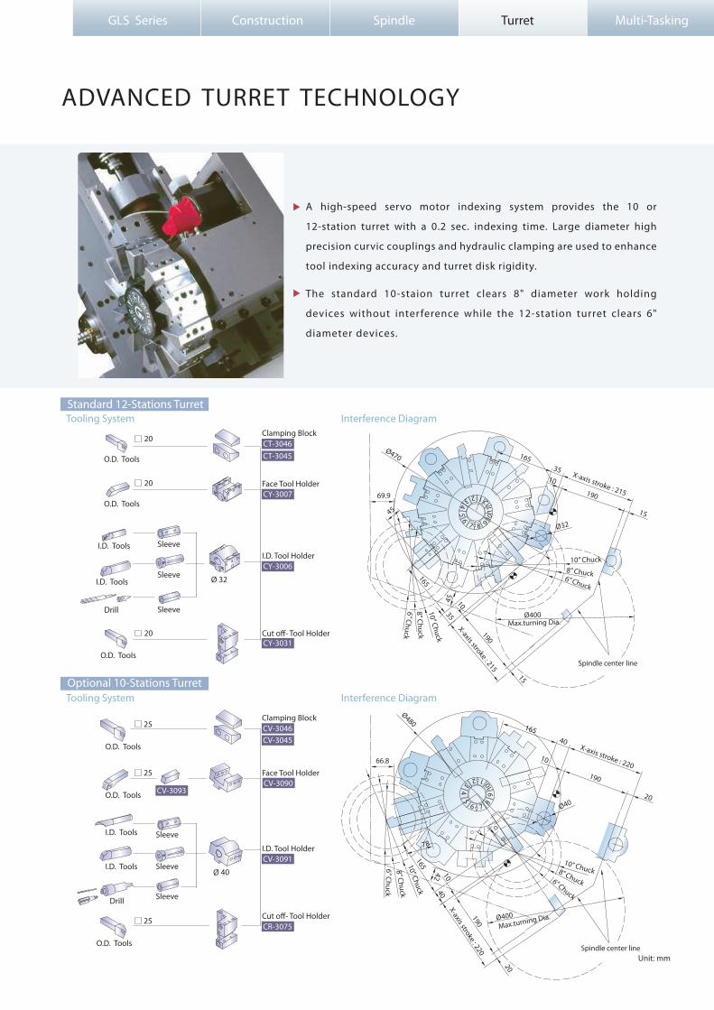
ADVANCED TURRET TECHNOLOGY
GLS Series Construction Spindle Turret Multi-Tasking
Unit: mm
A high-speed servo motor indexing system provides the 10 or
12-station turret with a 0.2 sec. indexing time. Large diameter high
precision curvic couplings and hydraulic clamping are used to enhance
tool indexing accuracy and turret disk rigidity.
The standard 10-staion turret clears 8" diameter work holding
devices without inter ference while the 12-station turret clears 6"
diameter devices.
1
4
7
1
6
6
8
5
3 2
7 854
23
910
1011
12
9
X-axis stroke : 215
X-axis stroke : 215
165
15
190
3510
Ø32
190
165
15
1045Ø470
Ø400Max.turning Dia.
Spindle center line
69.9
45
35
16540
190
20
X-axis stroke : 220
X-axis stroke : 220
165
4010
190
20
78
6” Chuck
6” Chuck
8” Chuck
8” Chuck
10” Chuck
10” Chuck
6” Chuck
8” Chuck
10” Chuck
6” Chuck
8” Chuck10” Chuck
10
42
Ø480
Ø40
66.8
Max.turning Dia.
Spindle center line
Ø400
Ø 32
Ø 40
CV-3045
CV-3090CV-3093
CV-3091
CR-3075
CT-3046
CY-3006
CY-3031
CT-3045
CY-3007
Clamping Block
Clamping Block
O.D. Tools
O.D. Tools
O.D. Tools
O.D. Tools
O.D. Tools
O.D. Tools
I.D. Tools
I.D. Tools
I.D. Tools
I.D. Tools
Sleeve
Sleeve
Sleeve
Sleeve
Sleeve
Sleeve
Face Tool Holder
Face Tool Holder
I.D. Tool Holder
I.D. Tool Holder
Cut o�- Tool Holder
Cut o�- Tool Holder
CV-3046
Drill
Drill
25
25
25
20
20
20
Tooling System Interference Diagram
Optional 10-Stations Turret
Tooling System Interference DiagramStandard 12-Stations Turret
5
6
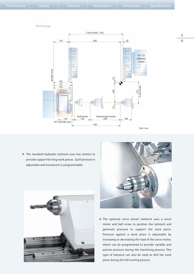
Work Range
Quill stroke Tailstock base stroke
X-ax
is s
trok
e
Z-axis stroke :
spin
dle
cove
r
108290150155
465
1019
015
215
147 500 20
520
6"Chuck8" Chuck
10"Chuck
The standard hydraulic tailstock uses live centers to
provide support for long work pieces. Quill pressure is
adjustable and movement is programmable.
The optional servo driven tailstock uses a servo
motor and ball screw to position the tailstock and
generate pressure to support the work piece.
Pressure against a work piece is adjustable by
increasing or decreasing the load of the servo motor,
which can be programmed to provide variable and
precise pressure during the machining process. This
type of tailstock can also be used to drill the work
piece during the OD turning process.
10 / 12 Stations
Turret
A2-5 Spindle nose
177165
183
Performance Quailty Features Automation Dimensions Speci�cations
Unit : mm

C1-axis Y-axis
X-axis
Z-axis
7
8
Y-AXIS MACHINING CAPABILITY
Y-axis control further enhances multi-tasking live tooling
capabilities and improves various machining precision. High
precision grooving and X-axis o�-center drilling are enabled.
With an abundant amount of
Y- a x i s t r a v e l , 70 mm= ±35mm
(2 . 7 5 ” = ± 1 . 3 7 ” ), a wide variety
of parts may be e�ciently
machined.
Grooving with Y-axis control produces
grooves with higher accuracy.
Y-axis travel direction
Finish Grooving
Grooving with Finish Pass Using Y-axis
Rough Grooving
Grooved pro�le
Required groovedpro�le
Grooving by Polar Coordinate Interpolation ( C-Axis )
Performance Quailty Features Automation Dimensions Speci�cations
On Y-axis equipped machines, the turret is mounted on a secondary 30
degrees wedge saddle on top of the X-axis slide. Guide ways are widely
spaced for maximum strength.

Drive Motor Power
Drive Motor
Max. Tapping Capacity
Max. Milling Capacity
Gear Ratio
1.2 kw (1.6 HP )
FANUC β8 / 3000 is
M8 * P1.25
Ø12 * 10
22 : 15
Live Tooling Turret SpecificationMachining Capability
Drill
End mill
Tapping
650
600
600
Spindle Speed
65
60
750
Feedrate
26.5
N/A
15
Cutting Speed
N/A
10
N/A
Cutting Depth
Ø13 HSS
Ø12 HSSend drill
M8 * P1.25
Tools( rpm ) ( mm/min ) ( m/min ) ( mm )
Raw Material : S45C Testing Model : GLS-150M
GOODWAY Multi-tasking machine can perform the functions below in one setup :
Keyway MillingSide Drilling & Tapping Contour MillingTurning
MACHINING PERFORMANCE
Face Drilling & Tapping
GLS Series Construction Spindle Turret Multi-Tasking
Sample Work Pieces
BRASS BRASS
S45C SUS304
S45C S45C
SCM3 A6061

For top component precision, Goodway utilizes top-end
measuring and balancing equipment such as ZEISS 3D
measuring system, BL high precision dynamic balancer
and many more.
PEAK QUALITY ASSURANCE
All machines are built with strict factory ISO 9001 Q/C
regulations.
Before leaving the assembly line, all machines must
pass critical testing including actual cutting, laser
inspection and more.
9
10
All machines undergo preprogrammed test runs of 100
hours or more before shipment.
Performance Quailty Features Automation Dimensions Speci�cations

FEATURES
Tri-color status light
Built-in lub. oilcollection system
The optional load monitoring function is used to detect
abnormal load of tools by monitoring the variation in spindle
motor and servo motor loads during the cutting process.
When abnormal loads are detected, the machine will stop at
program end (M30) or immediately (feed hold status) according
to tool life value or tool break value respectively.
GLS Series Construction Spindle Turret Multi-Tasking
Tool Setter
Load Monitoring
Coolant TankCoolant Pump
Chip Conveyor
The optional Renishaw HPMA tool presetter utilizes a
motorized arm to lower the tool probe into position. An auto
tool check function further increases tool touch-o�
e�ciency.
Coolant system features a roll-out
coolant tank for easy maintenance
and high-pressure coolant pump for
increased cooling power.
3-Jaw chuck w/ Soft Jaws x 1 set
The standard chip conveyor features adjustable timers that
allow the operator to set operation intervals according to the
amount of chips generated by the machine. Thus, reducing
coolant loss to a minimum.
10-station turret12-station turret12-station live tooling turretTool holder & sleeve packageLive tooling tool holders ( 0˚x2, 90˚x2 )
Renishaw HPMA tool presetter
TURRET
SPINDLE
WORK HOLDING
MEASUREMENT
AUTOMATIC OPERATION SUPPORT
CHIP DISPOSAL
COOLANT
Single-speed
6"8"
10"6"8"
10"
Chuck clampingTailstock thrust
Motorized arm
3 Kg/cm25 Kg/cm210 Kg/cm220 Kg/cm2
Right dischargeRear discharge
4 sets (8)8 sets (16)
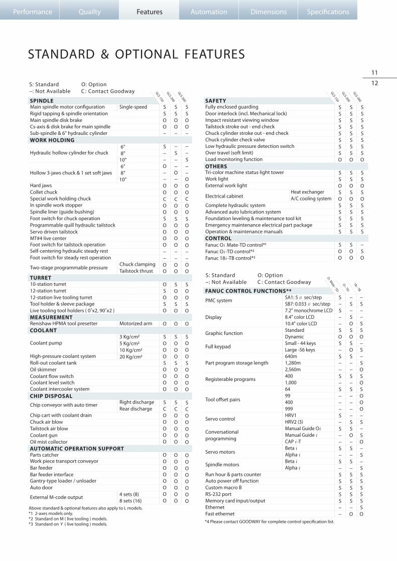
Main spindle motor con�gurationRigid tapping & spindle orientationMain spindle disk brakeCs-axis & disk brake for main spindleSub-spindle & 6" hydraulic cylinder
Hydraulic hollow cylinder for chuck
Hollow 3-jaws chuck & 1 set soft jaws Hard jawsCollet chuck Special work holding chuckIn spindle work stopperSpindle liner (guide bushing)Foot switch for chuck operationProgrammable quill hydraulic tailstockServo driven tailstockMT#4 live centerFoot switch for tailstock operationSelf-centering hydraulic steady restFoot switch for steady rest operation
Two-stage programmable pressure
Chip conveyor with auto timer
Chip cart with coolant drainChuck air blowTailstock air blowCoolant gunOil mist collector
Coolant pump
High-pressure coolant systemRoll-out coolant tankOil skimmerCoolant �ow switchCoolant level switchCoolant intercooler system
Parts catcher Work piece transport conveyorBar feederBar feeder interface Gantry-type loader / unloaderAuto door
External M-code output
SSOO−
S−−O−−OOCOOSOOOO−−OO
OSOSO
O
SOOOSOOOO
SCOOOOO
OOOOOOOO
SSOO−
−S−−O−OOCOOSOOOO−−OO
SOOSO
O
SOOOSOOOO
SCOOOOO
OOOOOOOO
SSOO−
−−S−−OOOCOOSOOOO−−OO
SOOSO
O
SOOOSOOOO
SCOOOOO
OOOOOOOO
GLS-150
GLS-200
GLS-260
FANUC CONTROL FUNCTIONS*4
SAFETY
OTHERS
CONTROL
Heat exchangerA/C cooling system
SA1: 5μ sec/stepSB7: 0.033μ sec/step7.2" monochrome LCD8.4" color LCD10.4" color LCDStandardDynamicSmall - 44 keysLarge -56 keys640m1,280m2,560m4001,0006499400999HRV1HRV2 (3)Manual Guide OiManual Guide i CAP i -TBeta i Alpha i Beta i Alpha i
Tri-color machine status light towerWork lightExternal work light
Electrical cabinet
Complete hydraulic systemAdvanced auto lubrication systemFoundation leveling & maintenance tool kitEmergency maintenance electrical part packageOperation & maintenance manuals
Fully enclosed guardingDoor interlock (incl. Mechanical lock)Impact resistant viewing windowTailstock stroke out - end checkChuck cylinder stroke out - end checkChuck cylinder check valveLow hydraulic pressure detection switchOver travel (soft limit)Load monitoring function
Fanuc Oi Mate-TD control*1Fanuc Oi -TD control*2Fanuc 18i -TB control*3
SSSSSSSSO
SSOSOSSSSS
SOO
SSSSSSSSO
SSOSOSSSSS
SOO
SSSSSSSSO
SSOSOSSSSS
−SO
GLS-150
GLS-200
GLS-260
PMC system
Display
Graphic function
Full keypad
Part program storage length
Registerable programs
Tool o�set pairs Servo control
Conversationalprogramming
Servo motors Spindle motors
Run hour & parts counterAuto power o� functionCustom macro BRS-232 portMemory card input/outputEthernetFast ethernet
Above standard & optional features also apply to L models.*1 2-axes models only.*2 Standard on M ( live tooling ) models.*3 Standard on Y ( live tooling ) models.
S−S−−SOS−S−−S−S−−−S−S−−S−S−SSSSS−−
−S−SOSOSOS−−S−S−−−−SSO−S−S−SSSSS−O
−S−−SSO−S−SOSOSOOO−S−SO−S−SSSSSSSO
*4 Please contact GOODWAY for complete control speci�cation list.
STANDARD & OPTIONAL FEATURES
S: Standard O: Option–: Not Available C : Contact Goodway
S: Standard O: Option–: Not Available C : Contact Goodway
11
12
Performance Quailty Features Automation Dimensions Speci�cations
Oi M
ate - TD
18i - TB
Oi - TD
GLS Series Construction Spindle Turret Multi-Tasking
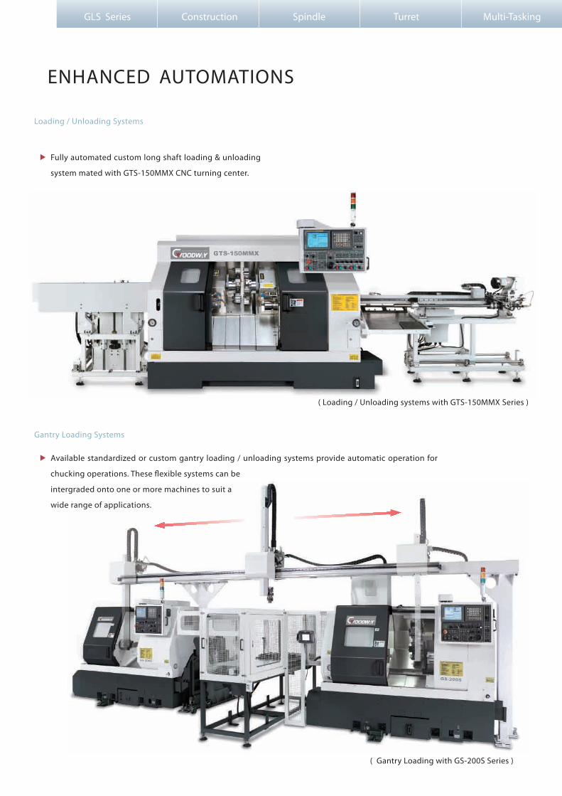
ENHANCED AUTOMATIONS
Available standardized or custom gantry loading / unloading systems provide automatic operation for
chucking operations. These �exible systems can be
intergraded onto one or more machines to suit a
wide range of applications.
( Gantry Loading with GS-200S Series )
( Loading / Unloading systems with GTS-150MMX Series )
Gantry Loading Systems
Loading / Unloading Systems
Fully automated custom long shaft loading & unloading
system mated with GTS-150MMX CNC turning center.

13
14
Model
Bar diameters
Maximum bar lengths*1
Magazine capacity
Control / drive type
Foot print
Weight
BF-65
5 ~ 65 mm ( 0.19”~2.55” )
1,220 mm ( 48” )
65 mm ( 2.55” ) x10 bars
Mitsubishi / Pneumatic
L 63” x D 44”
250 Kg ( 550 lb )
BF-80
6 ~ 80 mm ( 0.23”~3.14” )
1,525 mm ( 60” )
80 mm ( 3.14” ) x 7 bars
Mitsubishi / Servo
L 87” x D 57”
500 Kg ( 1,100 lb )
Bar Feeder
Actual bar length limited by total spindle + work piece length ( work piece + chuck + spindle + cylinder +
rear spindle cover lengths ). A bar supporting device must be used if bar extends past the rear spindle
cover, otherwise, the bar may bend during machining causing serious machine damage and injury or
death to operator.
Cut o�
Feed new barinto spindle
New bar feed against turret stop
Pushing forward Last piece cut o�
Machining
Remnant eject
Bar Feeding & Bar Change Cycle
Optional hydraulic parts catchers can be programmed to catch
�nished parts after cut-o�. Parts conveyor systems are also available.
Parts ConveyorParts Catchers
Performance Quailty Features Automation Dimensions Speci�cations
*1

GENERAL DIMENSION
GLS Series Construction Spindle Turret Multi-Tasking
A
B
305
C
OPERATOR
500
2,610
withoutChip Conveyor
with Chip conveyor
Direction of Assembly
Chip Conveyor
Direction of Dismantle
min
: 800
as re
quire
d1,
409
1,962500
1,00
0 R 850
Model
GLS-150 / 200 / 260
GLS-150 / 200 / 260 ( Y-axis )
A B C D E
Foot - Print
Machine Layout
Unit : mm
Unit : mm980 D
E
940
1,053
1,0001,6721,4952,095
1,0102,0571,6522,288
159 1,962 124

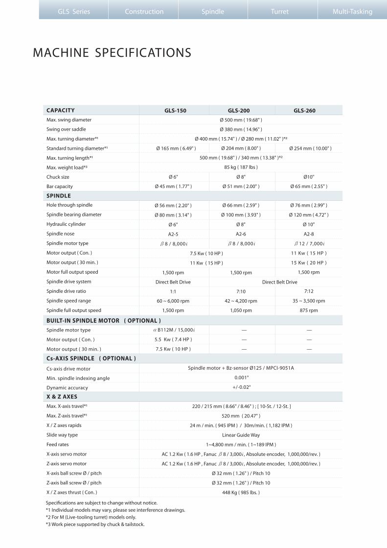
MACHINE SPECIFICATIONS
Max. swing diameter
Swing over saddle
Max. turning diameter*1
Standard turning diameter*1
Max. turning length*1
Max. weight load*3
Chuck size
Bar capacity
Hole through spindle
Spindle bearing diameter
Hydraulic cylinder
Spindle nose
Spindle motor type
Motor output ( Con. )
Motor output ( 30 min. )
Motor full output speed
Spindle drive system
Spindle drive ratio
Spindle speed range
Spindle full output speed
Cs-axis drive motor
Min. spindle indexing angle
Dynamic accuracy
Max. X-axis travel*1
Max. Z-axis travel*1
X / Z axes rapids
Slide way type
Feed rates
X-axis servo motor
Z-axis servo motor
X-axis ball screw Ø / pitch
Z-axis ball screw Ø / pitch
X / Z axes thrust ( Con. )
Speci�cations are subject to change without notice.*1 Individual models may vary, please see interference drawings.*2 For M (Live-tooling turret) models only.*3 Work piece supported by chuck & tailstock.
CAPACITY
SPINDLE
X & Z AXES
GLS-150 GLS-200 GLS-260
Ø 56 mm ( 2.20" )
Ø 80 mm ( 3.14" )
Ø 6"
A2-5
β8 / 8,000i
Ø 66 mm ( 2.59" )
Ø 100 mm ( 3.93" )
Ø 8"
A2-6
β8 / 8,000i
7.5 Kw ( 10 HP )
11 Kw ( 15 HP )
1,500 rpm
Direct Belt Drive
1:1
60 ~ 6,000 rpm
1,500 rpm
1,500 rpm
7:10
42 ~ 4,200 rpm
1,050 rpm
7:12
35 ~ 3,500 rpm
875 rpm
Direct Belt Drive
Spindle motor + Bz-sensor Ø125 / MPCI-9051A
0.001°
+/-0.02°
GLS Series Construction Spindle Turret Multi-Tasking
Spindle motor type
Motor output ( Con. )
Motor output ( 30 min. )
αB112M / 15,000i
5.5 Kw ( 7.4 HP )
7.5 Kw ( 10 HP )
—
—
—
—
—
—
220 / 215 mm ( 8.66" / 8.46" ) ; [ 10-St. / 12-St. ]
520 mm ( 20.47" )
24 m / min. ( 945 IPM ) / 30m/min. ( 1,182 IPM )
Linear Guide Way
1~4,800 mm / min. ( 1~189 IPM )
AC 1.2 Kw ( 1.6 HP , Fanuc β8 / 3,000i , Absolute encoder, 1,000,000/rev. )
AC 1.2 Kw ( 1.6 HP , Fanuc β8 / 3,000i , Absolute encoder, 1,000,000/rev. )
Ø 32 mm ( 1.26" ) / Pitch 10
Ø 32 mm ( 1.26" ) / Pitch 10
448 Kg ( 985 lbs. )
Ø 500 mm ( 19.68" )
Ø 380 mm ( 14.96" )
Ø 400 mm ( 15.74" ) / Ø 280 mm ( 11.02" )*2
Ø 204 mm ( 8.00" )
500 mm ( 19.68" ) / 340 mm ( 13.38" )*2
85 kg ( 187 lbs )
Ø 6"
Ø 45 mm ( 1.77" )
Ø 8"
Ø 51 mm ( 2.00" )
Ø10"
Ø 65 mm ( 2.55" )
Ø 76 mm ( 2.99" )
Ø 120 mm ( 4.72" )
Ø 10"
A2-8
β12 / 7,000i
11 Kw ( 15 HP )
15 Kw ( 20 HP )
1,500 rpm
Cs-AXIS SPINDLE ( OPTIONAL )
BUILT-IN SPINDLE MOTOR ( OPTIONAL )
Ø 165 mm ( 6.49" ) Ø 254 mm ( 10.00" )
17
18
Performance Quailty Features Automation Dimensions Speci�cations
Stations
Indexing drive
Indexing speed
Accuracy
OD tool shank size
ID tool shank size
340 mm ( 13.38" )
12
6 ( Live tooling tools rotate together )
AC 1.2 Kw ( 1.6 HP , Fanuc β8/3,000i , Absolute encoder, 1,000,000 / rev. )
7 N-m ( 5 ft-lbs. ) [ Con. ]
Fanuc AC Servo motor
0.2 sec. Adjacent / 0.5 sec. 180 degrees ( Single step )
□20 mm
Ø 25 mm
1 ~ 13 mm ( 0.04" ~ 0.51" ) ER 20 collets
10 ~ 4,400 RPM
Max. turning diameter
Max. X-axis travel
Max. Y-axis travel
X / Y axes rapids
Slide way type
Feed rates
X-axis servo motor
Y-axis servo motor
X-axis ball screw Ø / pitch
Y-axis ball screw Ø / pitch
X / Y axes thrust ( Con. )
280 mm ( Ø 11.02" )
195 mm ( 7.67" )
70 mm = ± 35 mm ( 2.75" = ± 1.37" )
24 m/min. ( 945 IPM ) / 10 m/min. ( 393 IPM )
Linear Guide Way
1 ~ 4,800 mm/min. ( 1 ~ 189 IPM )
AC 1.6 Kw ( 2.2 HP , Fanuc α8/3,000i , Absolute encoder, 1,000,000 / rev. )
AC 1.6 Kw ( 2.2 HP , Fanuc α8/3,000i , Absolute encoder, 1,000,000 / rev. )
Ø 32 mm ( 1.26" ) / Pitch 6
Ø 32 mm ( 1.26" ) / Pitch 6
513 Kg ( 1,026 lbs. ) / 513 Kg ( 1,026 lbs. )
Quill center taper
Quill diameter / travel
Tail stock base travel
Programmable quill / base
Programmable base type
MT#4 ( Live center required. )
Ø 70 mm ( 2.75" ) / 150 mm ( 5.90" )
290 mm ( 11.41" )
Yes / No
Servo motor + Ball screw
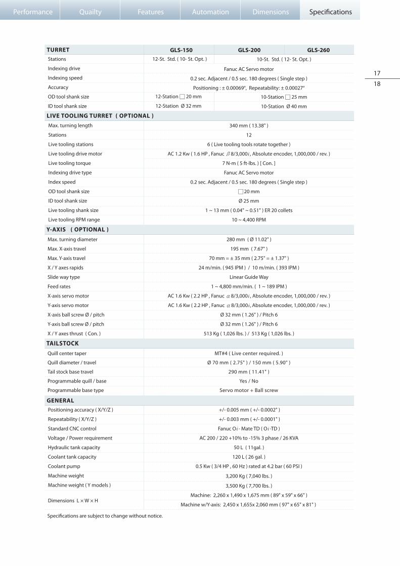
TURRET
GENERAL
GLS-150 GLS-200 GLS-260
Positioning accuracy ( X/Y/Z )
Repeatability ( X/Y/Z )
Standard CNC control
Voltage / Power requirement
Hydraulic tank capacity
Coolant tank capacity
Coolant pump
Machine weight
Machine weight ( Y models )
Dimensions L × W × H
LIVE TOOLING TURRET ( OPTIONAL )
Y-AXIS ( OPTIONAL )
TAILSTOCK
12-St. Std. ( 10- St. Opt. )
12-Station □ 20 mm
12-Station Ø 32 mm
Fanuc AC Servo motor
0.2 sec. Adjacent / 0.5 sec. 180 degrees ( Single step )
Positioning : ± 0.00069°, Repeatability: ± 0.00027°
+/- 0.005 mm ( +/- 0.0002" )
+/- 0.003 mm ( +/- 0.0001" )
Fanuc Oi - Mate TD ( Oi -TD )
AC 200 / 220 +10% to -15% 3 phase / 26 KVA
50 L ( 11gal. )
120 L ( 26 gal. )
0.5 Kw ( 3/4 HP , 60 Hz ) rated at 4.2 bar ( 60 PSI )
3,200 Kg ( 7,040 lbs. )
3,500 Kg ( 7,700 lbs. )
Machine: 2,260 x 1,490 x 1,675 mm ( 89" x 59" x 66" )
Machine w/Y-axis: 2,450 x 1,655x 2,060 mm ( 97" x 65" x 81" )
10-St. Std. ( 12- St. Opt. )
10-Station □ 25 mm
10-Station Ø 40 mm
Max. turning length
Stations
Live tooling stations
Live tooling drive motor
Live tooling torque
Indexing drive type
Index speed
OD tool shank size
ID tool shank size
Live tooling shank size
Live tooling RPM range
Speci�cations are subject to change without notice.
Copyr ight 2009 by Goodway Machine Corp. Al l r ight reservedG-GLS-150 SERIES-EN-F-20100519
No.589, Chengyang Road,Xiang Cheng Economic Development District Suzhou City, Jiangsu, ChinaTEL : + 86-512-6576-3699FAX : + 86-512-6576-7299Website : www.goodwaycnc.com.cnE-mail : [email protected]
GOODWAY MACHINE CORP.GOODWAY (SUZHOU) MACHINE CORP.
No.13, 5Th Road,Taichung Industrial Park,Taichung City, 407, Taiwan, R.O.C.TEL : + 886-4-2359-1226Website : www.goodwaycnc.comE-mail : [email protected]
No. 38, Keyuan Road, Central Taiwan Science Park.Taichung, Taichung City, 407, Taiwan, R.O.C.TEL : + 886-4-2463-6000FAX : + 886-4-2463-9600
Headquarters :
Central Taiwan Science Park Branch :