GOLDEN VIEW DRIVE - CRW Engineering€¦ · GOLDEN VIEW DRIVE RABBIT CREEK ROAD TO ROMANIA DRIVE...
97
GOLDEN VIEW DRIVE RABBIT CREEK ROAD TO ROMANIA DRIVE Design Study Report PRE-FINAL May 2013 MOA Project No. 10-026 Prepared for: Municipality of Anchorage, Public Works Department, Project Management & Engineering Division, 4700 Elmore Road, Anchorage, Alaska 99507 Prepared by: CRW Engineering Group, LLC 3940 Arctic Blvd. Suite 300 Anchorage, Alaska 99503 www.crweng.com G O L D E N V I E W D R I V E I N T E R S E C T I O N & S A F E T Y U P G R A D E S
Transcript of GOLDEN VIEW DRIVE - CRW Engineering€¦ · GOLDEN VIEW DRIVE RABBIT CREEK ROAD TO ROMANIA DRIVE...

GOLDEN VIEW DRIVERABBIT CREEK ROAD TO ROMANIA DRIVE
Design Study Report PRE-FINAL
May 2013MOA Project No. 10-026
Prepared for: Municipality of Anchorage, Public Works Department, Project Management & Engineering Division, 4700 Elmore Road, Anchorage, Alaska 99507
Prepared by: CRW Engineering Group, LLC3940 Arctic Blvd. Suite 300 Anchorage, Alaska 99503 www.crweng.com
GOLDEN VIEW DRIVE
INTERSECTION & SAFETY UPGRADES

MOA Project #10-026 Golden View Drive Intersection & Safety Upgrades
Executive Summary (May 2013) - 1 -
Executive Summary
Introduction
The Municipality of Anchorage Project Management and Engineering (MOA PM&E) has
contracted with CRW Engineering Group, LLC to provide professional services to evaluate
alternatives to upgrade Golden View Drive from Rabbit Creek Road to Romania Drive to
current Municipal collector road standards. This project is the number one priority for the
Rabbit Creek Community Council and a high priority for the South Goldenview Area Rural
Road Service Area, the Anchorage School District, the Traffic Engineering Division, and the
surrounding neighborhoods. Currently, the project has been funded with a $3 million State
grant for design and pre-construction tasks. Additional bond funding and State grants will be
necessary for ROW acquisition and construction.
Based on public and agency stakeholder input during the Concept Report Phase, the
primary goals of this project are as follows, in no particular order of importance:
• Improve the roadway to meet current MOA standards.
• Improve area drainage while maintaining creeks and flows to wetlands.
• Improve pedestrian and bicycle safety.
• Improve Golden View Drive/Bluebell Drive intersection.
• Evaluate solutions to address traffic congestion during peak hours on Golden View
Drive resulting from Goldenview Middle School traffic.
• Address speeding on Golden View Drive.
The Design Study Report evaluates existing and future conditions and a range of conceptual
design alternatives.
Recommended Improvements
The recommended typical cross section consists of two 11-foot lanes with 3.5-foot shoulders
and barrier curb and gutter. A single pedestrian facility is recommended: an 8-foot wide
paved pathway located on the west side, separated from the back of curb where feasible. A
drainage swale would be located on the east side.

MOA Project #10-026 Golden View Drive Intersection & Safety Upgrades
Executive Summary (May 2013) - 2 -
Other recommended improvements include:
• Posted Speed Limit: Based on recommendations from the Traffic Division and
approved by the Planning and Zoning Commission, the posted speed limit is to be
increased from 35 MPH to 40 MPH.
• Landscaping: Proposed landscaping will be in character with the adjacent residential
properties which is native in aesthetics. The focus will be on preserving existing
vegetation to the greatest extent practical, supplementing the landscaping with new
plantings when appropriate.
• Retaining Walls: Retaining walls are recommended, as appropriate, to minimize
impacts to adjacent utilities, properties, or the environment.
• Lighting: A continuous roadway LED lighting system, current with MOA standards, is
proposed.
• Storm Drain: The proposed drainage system is made up of five separate systems,
each with their own outfall. Site topography and existing stream and drainages
necessitate using separate systems. A large diameter storm drain main will extend
along a majority of the project length, serving as both a roadway runoff collection
system, and high runoff bypass system. Existing stream and drainage crossing
structures will be replaced and upgraded as required by modifications to the roadway
cross section.
Following is a summary of conceptual estimated costs for the proposed improvements for
Golden View Drive Upgrades.
Golden View Drive Typical Section

MOA Project #10-026 Golden View Drive Intersection & Safety Upgrades
Executive Summary (May 2013) - 3 -
Schedule Total
Roadway & Sidewalk Improvements1 $9,114,000
Storm Drainage Improvements $4,877,000
Illumination and Electrical Improvements $1,432,000
Landscaping $480,000
Subtotal Construction = $15,903,000
Contingency (20%) $3,181,000
Total Construction = $19,084,000
Utility Relocation $2,582,000
ROW Acquisition $100,000
Total = $21,766,000 Notes: 1. Estimated costs do not include improvements to Bluebell Drive. 2. Estimated construction and ROW acquisition costs do not include Rabbit Creek Road / Golden View Drive Intersection as this work will be dependent on the outcome of a future study being done by ADOT.

MOA Project #10-026 Golden View Drive Intersection & Safety Upgrades
Pre-Final Design Study Report May 2013 i
Table of Contents
I. Introduction ....................................................................................................................... 1
Concept Report Summary/Project Goals ........................................................................ 1 A.II. Existing Conditions .......................................................................................................... 5
Area Context ................................................................................................................... 5 A. Facility Description .......................................................................................................... 5 B. Land Use and Ownership ................................................................................................ 9 C. Geotechnical Summary ................................................................................................... 9 D. Environmental ............................................................................................................... 11 E. Drainage ........................................................................................................................ 13 F. Vegetation/Landscaping ................................................................................................ 17 G. Utilities ........................................................................................................................... 18 H.1. Water .......................................................................................................................... 18 2. Sewer ......................................................................................................................... 19 3. Natural Gas................................................................................................................. 20 4. Electric ........................................................................................................................ 21 5. Telephone ................................................................................................................... 22 6. Cable Television ......................................................................................................... 22
III. Traffic and Safety Analysis ..........................................................................................24 Existing Traffic Volume & Speed Data ........................................................................... 24 A. Traffic Projections .......................................................................................................... 27 B. Traffic Characteristics .................................................................................................... 30 C. Crash Data .................................................................................................................... 31 D. Operational Analysis ...................................................................................................... 32 E.1. Segment Analysis – Golden View Drive ...................................................................... 32 2. Intersection Analysis ................................................................................................... 33 Side Street Intersections/Access Control ....................................................................... 34 F.
IV. Stakeholder/Public Involvement ..................................................................................34 V. Design Criteria .................................................................................................................36
Design Standards .......................................................................................................... 36 A.1. Municipality of Anchorage ........................................................................................... 37 2. State of Alaska ............................................................................................................ 37 3. Federal ....................................................................................................................... 37 Design and Posted Speed ............................................................................................. 38 B.School Speed Zone: .......................................................................................................... 39 Accessibility Guidelines ................................................................................................. 39 C. Typical Section .............................................................................................................. 39 D. Clear Zone .................................................................................................................... 40 E. Lighting .......................................................................................................................... 40 F. Landscaping .................................................................................................................. 41 G. Design Criteria Summary............................................................................................... 43 H.
VI. Design Alternatives ......................................................................................................44 Design Challenges ........................................................................................................ 44 A. Golden View Drive Alignment and Profile ...................................................................... 45 B.1. Golden View Drive Profile ........................................................................................... 45

MOA Project #10-026 Golden View Drive Intersection & Safety Upgrades
Pre-Final Design Study Report May 2013 ii
2. Golden View Drive Profile at Bluebell Drive:................................................................ 47 Local Side Street Alignments and Profiles ..................................................................... 54 C.1. Golden View Drive, south of Romania Drive ............................................................... 54 2. Bluebell Drive .............................................................................................................. 58 3. Ransom Ridge Road ................................................................................................... 58 4. Horizontal Curves ....................................................................................................... 59 Roadway Cross Section ................................................................................................ 60 D. Pedestrian Facilities ...................................................................................................... 62 E.1. Alternative 1: Pathway west side only ......................................................................... 62 2. Alternative 2: Pathway on west side, sidewalk on east side ........................................ 63 3. Alternative 3: Pathway west side, sidewalk on east side partial length ........................ 63 4. Alternative 4: Pathway west side, sidewalk on east side partial length ........................ 63 5. Alternative 5: Pathway east side only .......................................................................... 63 Side Street Intersections/Access Control ....................................................................... 65 F. Rabbit Creek Road/Golden View Drive Intersection....................................................... 65 G. Structural Section .......................................................................................................... 66 H.
Retaining Walls ............................................................................................................. 67 I.1. Retaining Wall Types .................................................................................................. 67 2. Considerations ............................................................................................................ 68 3. Estimated Project Cost ............................................................................................... 72 Traffic Calming .............................................................................................................. 73 J. Lighting .......................................................................................................................... 74 K. Landscaping .................................................................................................................. 76 L. Trails ............................................................................................................................. 77 M. Cluster Mailboxes .......................................................................................................... 78 N. Parking .......................................................................................................................... 78 O.
VII. Drainage Analysis ........................................................................................................79 Existing Planning Documents ........................................................................................ 79 A. Storm Water Model........................................................................................................ 79 B. Proposed Drainage System ........................................................................................... 81 C.
VIII. Right-of-Way Impacts ...................................................................................................84 Overview ....................................................................................................................... 84 A. Right-of-Way Easements/Permits .................................................................................. 85 B.
IX. Design Recommendations ...........................................................................................86 Roadway ....................................................................................................................... 86 A. Structural Section .......................................................................................................... 86 B. Retaining Walls ............................................................................................................. 86 C. Drainage ........................................................................................................................ 87 D. Traffic Calming .............................................................................................................. 87 E. Lighting .......................................................................................................................... 87 F. Landscaping .................................................................................................................. 87 G. Design Cost Estimate .................................................................................................... 88 H.

MOA Project #10-026 Golden View Drive Intersection & Safety Upgrades
Pre-Final Design Study Report May 2013 iii
List of Figures
Figure 1 – Location Map ............................................................................................................ 3 Figure 2 – Project Vicinity Map ................................................................................................... 4 Figure 3 – Area Zoning, Roadway Classifications, and Bus Stops ............................................. 8 Figure 4 – Wetlands Map ..........................................................................................................12 Figure 5 – Existing Drainage Map .............................................................................................16 Figure 6 – AWWU and HDP water and sewer service area boundary .......................................20 Figure 7 – Existing Peak Hour Turning Movement Counts ........................................................25 Figure 8 – Projected AADT (design year 2033) .........................................................................28 Figure 9 – Projected Peak Hour Turning Movement Counts ......................................................29 Figure 10 – Roadway profile split at Bluebell Drive ...................................................................52 Figure 11 – Proposed Grades along Golden View thru intersection with Romania ....................55 Figure 12 – Sweep from Golden View Drive to Romania Drive .................................................57 Figure 13 – Proposed Typical Cross Section ............................................................................61

MOA Project #10-026 Golden View Drive Intersection & Safety Upgrades
Pre-Final Design Study Report May 2013 iv
List of Tables
Table 1 – Existing AADT Traffic Data ........................................................................................24 Table 2 – Speed Study Results .................................................................................................26 Table 3 – 1999-2008 Crash Summary for Intersections on Golden View Drive .........................31 Table 4 – Golden View at E. 156th & Prominence Pointe Operational Analysis ........................33 Table 5 – Design Criteria Summary ..........................................................................................43 Table 6 – Summary of Retaining Walls (preferred alternative) ..................................................73 Table 7 – Summary of storm water runoff .................................................................................80 Table 8 – Estimated Right-of-Way Easements/Permits .............................................................85 Table 9 – Summary of Estimated Construction Costs ...............................................................88
Appendices
Appendix A: Concept Report Appendix B: Roadway Plan and Profile Sheets Appendix C: Existing Utilities Appendix D: Traffic Analysis Report and Data Appendix E: Geotechnical Analysis Appendix F: Drainage Analysis Appendix G: Rabbit Creek Road/Golden View Drive Intersection Alternative Report Appendix H: Bluebell Drive Design Study Memorandum Appendix I: Right-of-Way Analysis Appendix J: Cost Estimates Appendix K: Agency Review Comment Summary

MOA Project #10-026 Golden View Drive Intersection & Safety Upgrades
Pre-Final Design Study Report May 2013 v
Abbreviations
AADT Annual Average Daily Traffic volume (vehicles per day) AASHTO American Association of State Highway Transportation Officials AASHTOGB AASHTO Policy on Geometric Design of Highways and Streets ACS Alaska Communication Systems ADA Americans with Disability Act ADEC Alaska Department of Environmental Conservation ADF&G Alaska Department of Fish and Game ADNR Alaska Department of Natural Resources ADT Average Daily Traffic volume (vehicles per day) ADOT&PF/DOT Alaska Department of Transportation and Public Facilities AFD Anchorage Fire Department AMATS Anchorage Metropolitan Area Transportation Solutions AMC Anchorage Municipal Code ASD Anchorage School District ATP Areawide Trails Plan AWWU Anchorage Water and Wastewater Utility BOC Back of curb CEA Chugach Electric Association cfs Cubic foot per second CMP Corrugated Metal Pipe DCM Municipality of Anchorage Design Criteria Manual DHV Design Hour Volume DIP Ductile Iron Pipe DSR Design Study Report EB Eastbound EOP End of Project GCI General Communications, Inc. EPA Environmental Protection Agency ESCP Erosion and Sediment Control Plan HDPE High density polyethylene pipe IESNA Illumination Engineering Society of North America ITE Institute of Traffic Engineers LOS Level of Service MOA Municipality of Anchorage MPH Miles per hour MUTCD Manual of Uniform Traffic Control Devices NB Northbound OS&HP Official Streets and Highways Plan PCM ADOT&PF Pre-Construction Manual PCMP Pre-coated Corrugated Metal Pipe PM&E Project Management and Engineering PUE Public Use Easement ROW Right-of-way SB Southbound sf Square feet SWMM Storm Water Management Model SWPPP Storm Water Pollution Prevention Plan TCP Temporary Construction Permit UDC Urban Design Commission USACE US Army Corps of Engineers vpd Vehicles per day WB Westbound WSM Watershed Management

MOA Project #10-026 Golden View Drive Intersection & Safety Upgrades
Pre-Final Design Study Report May 2013 1
I. Introduction The Municipality of Anchorage Project Management and Engineering (MOA PM&E) has
contracted with CRW Engineering Group, LLC to provide professional services to evaluate
alternatives to upgrade Golden View Drive from Rabbit Creek Road to Romania Drive to current
Municipal collector road standards. See FIGURES 1 AND 2 for Location and Project Vicinity maps.
The scope of work includes a determination of appropriate design criteria to be used for the
proposed improvements. This project is the number one priority for the Rabbit Creek
Community Council and a high priority for the South Goldenview Area Rural Road Service Area
(RRSA), the Anchorage School District, the Traffic Engineering Division, and the surrounding
neighborhoods. Currently, the project has been funded with a $3 million State grant for design
and pre-construction tasks. Additional bond funding and State grants will be necessary for right-
of-way (ROW) acquisition and construction.
Concept Report Summary/Project Goals A.
Using the MOA Context Sensitive Solutions (CSS)
Policy as a guideline, the Golden View Drive Intersection
and Safety Upgrades Concept Report was prepared.
The goal of the CSS process is to collaborate with
stakeholders to improve the safety and mobility of the
corridor, balance diverse interests, and to find areas of
compromise that address budget and environmental
concerns. The CSS policy provides guidelines to involve
project stakeholders in defining the problems to be
solved and a conceptual range of potential solutions to
address the problems. The full Concept Report and
range of stakeholder activities can be found in APPENDIX
A. The CSS process will continue throughout the design
phase of the project with additional opportunities for
stakeholders to obtain information and provide feedback
through the web page, e-newsletter updates, open
houses, community council presentations, and direct
feedback through phone calls and e-mail.

MOA Project #10-026 Golden View Drive Intersection & Safety Upgrades
Pre-Final Design Study Report May 2013 2
Based on public and agency stakeholder input during the Concept Report Phase, the
primary goals of this project are as follows, in no particular order of importance:
• Improve the roadway to meet current MOA standards.
• Improve area drainage while maintaining creeks and flows to wetlands.
• Improve pedestrian and bicycle safety.
• Improve Golden View Drive/Bluebell Drive intersection.
• Evaluate solutions to address traffic congestion during peak hours on Golden View
Drive resulting from Goldenview Middle School traffic.
• Address speeding on Golden View Drive.
The community also placed a high importance on improving the Rabbit Creek Road/Golden
View Drive intersection. The Rabbit Creek Road/Golden View Drive Intersection Alternative
Report was prepared as part of the initial Design Study Phase; however, further work on the
intersection is pending a study by the Alaska Department of Transportation (ADOT) of all of
the hillside intersections.
To achieve the above goals, the Design Study Report (DSR) evaluates the need for the
improvements to the roadway and pedestrian facilities, surface and subsurface drainage,
pedestrian and vehicular connectivity, landscaping, signalization, and lighting. The No Build
alternative is not considered in this report as it is not supported by project stakeholders and
does not address the problems that need to be resolved.

GO
LDEN
VIE
W D
RIV
E
RABBIT CREEK
ROAD
OLD SEW
ARD
SEWARD HWY
MO
UN TAIN AIRELM
OR
E
³Golden View Drive Intersection & Safety Upgrades
MOA Project #10-026
PROJECT LOCATION
Pre‐FinalDesignStudyReportMay2013 3
Figure 1 - Project Location Map
Knik Arm
Turnagain Arm
Anchorage, AK


MOA Project #10-026 Golden View Drive Intersection & Safety Upgrades
Pre-Final Design Study Report May 2013 5
II. Existing Conditions
Area Context A.
Land uses are a mix of large lots with lower density residential served by private wells and
septic, and newer subdivisions served by water and sewer that are more dense
(Prominence Pointe and Golden View Park). There are also significant tracts of
undeveloped, residentially-zoned land near the south end of Golden View Drive and at the
southeast corner of Golden View Drive and Rabbit Creek Road. Moen Park, a 10-acre
neighborhood park near the south end of the corridor, has play equipment for toddlers and a
small parking lot. Golden View Middle School is located at the northern end of the corridor.
Students attending Goldenview Middle School, Bear Valley Elementary School and South
Anchorage High School are all bussed from stops along Golden View Drive. Golden View
Drive is also the only winter access to Paradise Valley, a neighborhood at the south end.
Little Survival Creek and Little Rabbit Creek along with associated wetlands, tributaries, and
multiple drainage channels meander throughout the project area. Topography is generally
steep providing views towards the Anchorage Bowl and Cook Inlet. Vegetation along the
corridor is typically a mix of birch, spruce and alder and often provides a buffer between
homes and the roadway. Moose and bear frequent the area.
Facility Description B.
Golden View Drive is a collector roadway on the Anchorage hillside that serves several
adjacent residential neighborhoods and Goldenview Middle School. Golden View Drive was
annexed into the Anchorage Roads and Drainage Service Area (ARDSA) in 2008; however,
Area zoning is a mix of newer subdivision and lower density, larger lots.

MOA Project #10-026 Golden View Drive Intersection & Safety Upgrades
Pre-Final Design Study Report May 2013 6
the adjacent parcels and the roads to the west and east are still in the South Goldenview
Area RRSA.
The existing roadway has two 11-foot wide, strip-paved lanes with a 2-foot wide gravel
shoulder on the east side. On the west side, there is:
• A 100-foot long separated asphalt
pathway that extends south from
Rabbit Creek Road along the west
side of Golden View Drive (see
photo, right);
• A 6-foot wide paved, designated
bicycle lane from Rabbit Creek
Road to Bridgeview Drive;
• And south of Bridgeview Drive,
there is an 8-foot wide gravel
shoulder.
There are no other pedestrian/non-motorized facilities along Golden View Drive. ASD has
designated Golden View Drive as a “hazardous walking route” due to the lack of
pedestrian/bicycle facilities. As a result, all students attending Goldenview Middle School
are bussed.
There is a northbound right turn lane at the Rabbit Creek Road intersection and the posted
speed along the corridor is 35 MPH.
The public ROW varies between approximately 60 to 80 feet for the majority of the project
corridor; however, the ROW width is 100 feet north of the Rabbit Creek culvert and also just
north and south of Bluebell Drive.
Separated pathway at Rabbit Creek Road/ Golden View Drive intersection

MOA Project #10-026 Golden View Drive Intersection & Safety Upgrades
Pre-Final Design Study Report May 2013 7
Rabbit Creek Road is a state-owned minor arterial west (downhill) of Golden View Drive and
a collector to the east (uphill) . It has two 12-foot travel lanes with 6-foot shoulders. There
are channelized eastbound left and right turn lanes onto Golden View Drive. There is also a
channelized westbound left turn onto Golden View Drive. The posted speed limit is 45 MPH.
There are no pedestrian or non-motorized facilities along Rabbit Creek Road near the
project corridor.
People Mover Transit does not currently serve Golden View Drive. The nearest bus stop is
Route 60 along the Old Seward Highway and Huffman Road.
Anchorage School District has bus stops for Bear Valley Elementary School (Route #13),
Golden View Middle School (Route #27), and South Anchorage High School (Route #14) to
serve students living on Golden View Drive and adjacent neighborhoods. The busses stop
at E. 172nd Avenue, Ransom Ridge Road, Prominence Pointe Drive, E. 164th Avenue, E.
162nd Avenue, and E. 156th Avenue. Busses use the mailbox pullout south of Bluebell Drive
to turn-around. Parents frequently park along Golden View Drive to wait for their children to
be picked up or dropped off from the busses.
Rabbit Creek Road at Golden View Drive, looking west

Woo
ds P
o int
e
Spai
n
E. 172nd
Virg
o
E. 164th
Bet
tijea
n
E. 162nd
Bridgeview
Luna
Eliz
abet
h
Ash
land
Davi
s
Sandpiper
Win
d S
ong
Longbow
Ricky
Steambo
at
Cape Sev
ille
Feod
osia
Bet
ty
Belarde
Blue
bell
Prominence Pointe
Romania
Sai
nt J
ames
Cobb
lest
one
Hill
Nobl
e Po
int
Azalea
Far V
iew
Will
s
E. 156th
w
Kallander
Mou
ntain
side
Villa
ge
Sai
nt J
ohn'
s
Norw
ay
Bria
rclif
f Rid
ge
Ston
e R
idge
Mes
a
Lost
Horizo
nS
now
Fla
ke
Austria
Switzerland
Rosemont
Mar
ijane
Gol
den
View
Bria
rclif
f Poi
nte
Arie
s
Eve
rgre
en R
idge
Ess
ex P
ark
Manytell Andover
Buf
falo
Robin Hood
Stanw
ood
Shangri-La
Pol
lock
Cloudcroft
Hillandale
Bla
ir Vi
ew
Seville
E. 160th
Ran
som
Rid
ge
Jensen
Woo
dridg
e
Gol
den
View
Driv
e
Rabbit Creek Road
R-6
R-6
PLI R-9
R-7
R-3 SL
R-9
R-6
R-7
R-3 SL
R-6
PLI
R-7 SL
R-10 SL
R-10 SL
R-6
R-7
R-10 SL
R-9
R-7
R-6 SL
PLI-p
R-7 SL
PLIR-3 SL
³Golden View Drive Intersection & Safety Upgrades
MOA Project #10-026
Pre‐FinalDesignStudyReportMay2013 8
Figure 3 - Area Zoning, Roadway Classifications, & Bus Stops
ParksPLI = Public Lands & InstitutesPLI SL = Public Lands, Special LimitationsR-3 SL = Multi Family Residential, Special LimitationsR-6 = Suburban Residential
R-6 SL = Suburban, Special LimitationsR-7 = Intermediate Rural ResidentialR-7 SL = Intermediate Rural, Special Limitations
R-9 = Rural ResidentialR-10 SL = Residential Alpine, Special LimitationsLocal RoadCollector RoadMinor Arterial
LEGENDProject AreaASD School Bus Stop
cP
cP
cP
cP
cP
cP
cP
PLI
R3-SL
Collector (Class I)
Minor Arterial(Class II)
NeighborhoodCollector (Class IC)
Collector (Class I) NeighborhoodCollector (Class IB)
MOA Project #10-026 Golden View Drive Intersection & Safety Upgrades
Pre-Final Design Study Report May 2013 9
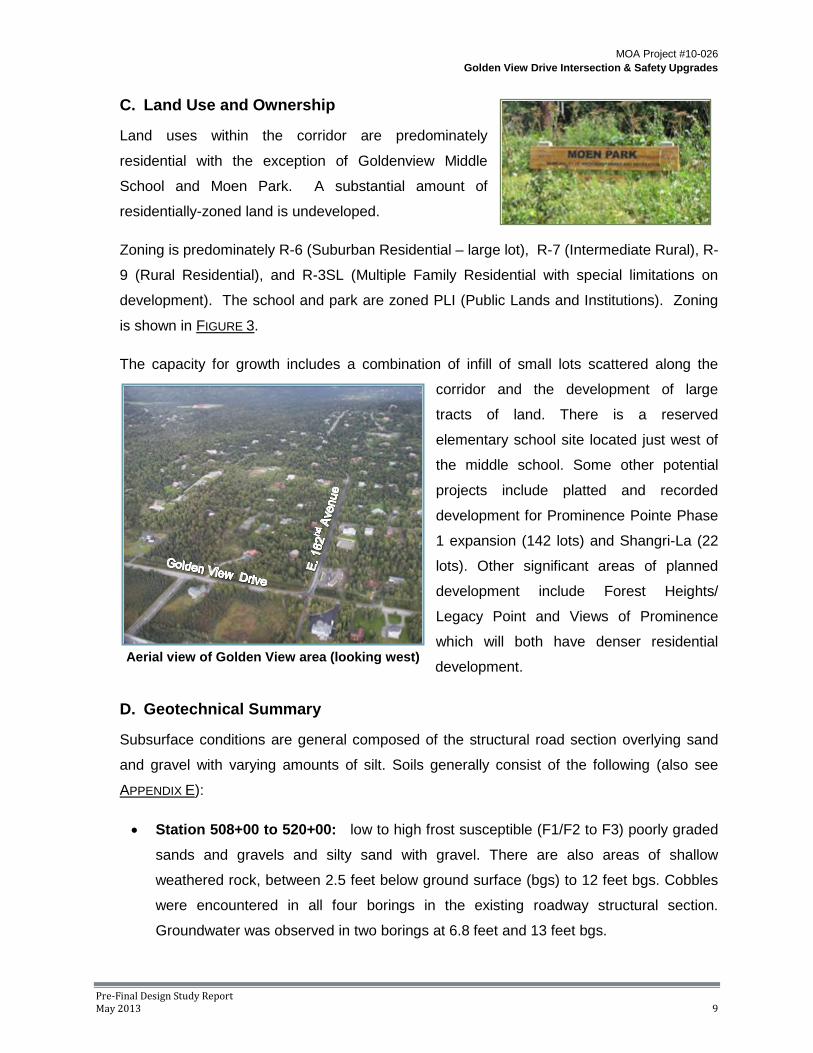
Land Use and Ownership C.
Land uses within the corridor are predominately
residential with the exception of Goldenview Middle
School and Moen Park. A substantial amount of
residentially-zoned land is undeveloped.
Zoning is predominately R-6 (Suburban Residential – large lot), R-7 (Intermediate Rural), R-
9 (Rural Residential), and R-3SL (Multiple Family Residential with special limitations on
development). The school and park are zoned PLI (Public Lands and Institutions). Zoning
is shown in FIGURE 3.
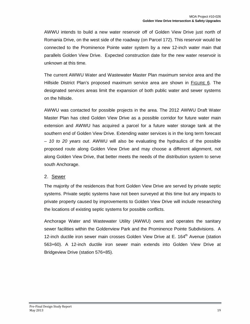
The capacity for growth includes a combination of infill of small lots scattered along the
corridor and the development of large
tracts of land. There is a reserved
elementary school site located just west of
the middle school. Some other potential
projects include platted and recorded
development for Prominence Pointe Phase
1 expansion (142 lots) and Shangri-La (22
lots). Other significant areas of planned
development include Forest Heights/
Legacy Point and Views of Prominence
which will both have denser residential
development.
Geotechnical Summary D.
Subsurface conditions are general composed of the structural road section overlying sand
and gravel with varying amounts of silt. Soils generally consist of the following (also see
APPENDIX E):
• Station 508+00 to 520+00: low to high frost susceptible (F1/F2 to F3) poorly graded
sands and gravels and silty sand with gravel. There are also areas of shallow
weathered rock, between 2.5 feet below ground surface (bgs) to 12 feet bgs. Cobbles
were encountered in all four borings in the existing roadway structural section.
Groundwater was observed in two borings at 6.8 feet and 13 feet bgs.
Aerial view of Golden View area (looking west)

MOA Project #10-026 Golden View Drive Intersection & Safety Upgrades
Pre-Final Design Study Report May 2013 10
Little Rabbit Creek
• Station 520+00 to 537+00: low to moderate frost susceptible (F1 to F2) poorly
graded sands and gravels, silty sand with gravel, and areas of high frost susceptible
soils (F2/F3). Cobbles were encountered in four of the five borings in the existing
roadway structural section. Groundwater was encountered in three of the borings at 4
feet, 11 feet, and 16 feet bgs.
• Station 537+00 to 585+00: non-frost to high frost susceptible (NFS to F3) poorly
graded sands and gravels, silty gravel with sands, and silty sand with gravel. Peat
was encounter in two borings at 16 feet bgs and 2.5 feet bgs. Cobbles were
encountered in the majority of the borings in the existing roadway structural section.
Groundwater was observed in ten of the borings at between 7 and 14.5 feet bgs.
• Station 585+00 to 601+00: low to high frost susceptible (F1 to F2/F3) poorly graded
sands and gravels, silty gravel with sand, and silty sand with gravel. Cobbles were
encountered in seven of the eight all of the boreholes. Groundwater was observed in
four of the eight of the boreholes, at depths of between 6.3 feet and 15 feet bgs.
Piezometers were installed in selected boreholes and follow up groundwater measurements
taken between August and October 2011 indicated that the groundwater rose considerably
in all but one of the 33 borings.

MOA Project #10-026 Golden View Drive Intersection & Safety Upgrades
Pre-Final Design Study Report May 2013 11
Typical stream tributary
Environmental E.
Based on a review of the Anchorage Wetlands Management Plan and the MOA Wetlands
Atlas, 2008 Edition, there are numerous mapped wetland and streams within the project
corridor (FIGURE 4). Little Survival Creek and Little Rabbit Creek along with associated
wetlands, tributaries, and multiple drainage channels meander throughout the project area.
Both Little Rabbit Creek and Little Survival Creek are listed as “Impaired Water Bodies” by
the ADEC for fecal coliform bacteria resulting from urban runoff. As such, these creeks
require measures to maintain and restore the creek’s water functions.
The project team held a meeting with the U.S. Army Corps of Engineers (USACE) on
December 6, 2011 to introduce the project and discuss options to avoid, minimize, and
mitigation potential impacts to jurisdictional waters of the U.S. Based on initial information
and observations, it should be
anticipated that the majority of the
drainage channels will be jurisdictional
waters and the USACE will be
concerned about maintaining flows to
downstream wetlands. During the
Design Phase, all wetlands, streams and
drainage channels within the project
corridor will be delineated and a
jurisdictional determination will be
submitted to the USACE for concurrence
and subsequent permitting.

Kallander Avenue
Rabbit Creek Road
Gol
den
View
Driv
e
Bridgeview Drive
Romania Drive
Eliz
abet
h St
reet
East 172nd Avenue
Bulgaria Drive
Prominence Pointe Drive
East 164th Avenue
East 162nd Avenue
Bluebell Drive
Ricky Road East 156th Avenue
Ransom Ridge Road
P
P
BB
B
D
B
B
C
B
D
B
P
C
P
B
C
B
D
B
U
P
D
B
B
D
D
P
H
D
C
D
C
D
C
D
D
D
DU
D
DD
D
D
D
D
A
Little Rabbit Creek
Potter Creek
³Golden View Drive Intersection & Safety Upgrades
MOA Project #10-026
Pre‐FinalDesignStudyReportMay2013
12
Figure 4 - Wetlands Map
Legend
Project Area
Stream
Wetlands & Designation

MOA Project #10-026 Golden View Drive Intersection & Safety Upgrades
Pre-Final Design Study Report May 2013 13
Drainage F.
Existing drainage facilities along Golden
View Drive consist primarily of roadside
ditches, channels, and culverts. A number
of the ditches and open channels have
been mapped by MOA Watershed
Management Section (WMS) as drainage
ways and are expected to be included
under USACE jurisdiction. Based on visual
inspection, the condition of these systems
vary greatly. Many of the conveyance
facilities have electrical heat trace
installations including: heat trace in conduit
mounted in culverts and structures, bare
heat trace in culverts and ditches, and
heat trace in conduit staked in ditches.
A segment of buried storm drain pipe runs along Golden View Drive from station 555+05 to
station 564+21. A subdrain which runs from station 555+00 to station 558+30 is connected
to this system, from there it is conveyed to just north of E. 164th Avenue and discharged into
an open channel.
There are nine stream crossings along the project
corridor, with existing culvert sizes varying from 18 to 72
inches in diameter. Seven of the streams are first order.
One is second order; North Branch South Fork Little
Rabbit Creek, and Little Rabbit Creek is third order.
Third order streams are subject to higher scrutiny in
regards to passing flows from larger flood events.
Perched culvert at stream crossing
Typical roadside ditch

MOA Project #10-026 Golden View Drive Intersection & Safety Upgrades
Pre-Final Design Study Report May 2013 14
Typical Stream and culvert
Golden View Stream Crossings
Stream Name Crossing Station
Catchment Area (Acres) Order
Potter Branch 508+50 30 1 South Fork Little Survival Creek 522+15 36 1 South Branch Little Survival Creek 529+35 43 1 Little Survival Creek 535+70 357 1 North Branch Little Survival Creek 554+55 109 1 South Branch South Fork Little Rabbit Creek 570+05 192 1 North Branch South Fork Little Rabbit Creek 585+65 101 2 Little Rabbit Creek 595+60 4800 3 Elmore Creek 605+00 102 1
Drainage within the project area is influenced by steep grades, shallow bedrock, and
shallow groundwater. Bedrock is as shallow as 2.5 feet in places, reducing space for
groundwater to flow and effectively forcing it to the surface. There is a high incidence of
groundwater seeps, particularly at cut banks for roads, ditches, and residences. These
groundwater seeps are highly susceptible to freezing and icing problems in certain locations.
The conditions described also result in substantial base flow in roadside ditches and
drainages. Water that would have otherwise been subsurface is daylighted at road cuts,
driveways, and ditches where it accumulates and flows over the ground. This intermittent
groundwater contributes to a significant and typically steady base flow in many ditches,
drainage ways, and small streams.
Icing, also referred to as glaciation or aufeis,
affects numerous locations along the project
corridor. Typical locations are at driveway
culvert crossings, roadway cut banks, and
shallow-sloped, flat-bottom ditches. Severity
of icing is variable and depends on a number
of conditions, including: air temperature
throughout the winter season, snow cover,
wind, and depth of frost penetration.

MOA Project #10-026 Golden View Drive Intersection & Safety Upgrades
Pre-Final Design Study Report May 2013 15
Mid-winter thaw events typically exacerbate icing as daytime temperatures rise above
freezing, creating runoff which later freezes at culverts and other constrictions created by
roadway snow removal and storage. Many of the ditches and associated culverts are within
the snow plow side-cast and snow storage area. The plowed snow is piled over culvert
inlets, and even driven over by vehicles, creating a plugged-inlet condition when thaw
events occur.
There are numerous private driveways that adjoin Golden View Drive. Crossing culverts
are installed to maintain roadside-ditch connectivity. Many of these driveways culverts
suffer from ineffective maintenance and have accumulations of sediment, vegetation and
trash. Culverts with shallow cover and restricted inlets as described are very susceptible
to icing. The existing storm drain system is shown in FIGURE 5.
Glaciation along Golden View Drive

Kallander Avenue
POTTER BRANCH
SOUTH FORKLITLE SURVIVAL CREEK
SOUTH BRANCH
LITTLE SURVIVAL
CREEK
NORTH BRANCH
LITTLE SURVIVAL CREEK
SOUTH BRANCH SOUTH FORKLITTLE RABBIT CREEK
NORTH BRANCHSOUTH FORK
LITTLE RABBIT CREEK
Rabbit Creek Road
Gol
den
View
Driv
e
Bridgeview Drive
Romania Drive
Eliz
abet
h St
reet
East 172nd Avenue
Bulg
Prominence Pointe Drive
East 164th Avenue
East 162nd Avenue
Bluebell Drive
Ricky Road East 156th Avenue
Ransom Ridge Road
LITTLE RABBIT CREEK
ELMORE CREEK
LITTLE SURVIVAL CREEK
³Golden View Drive Intersection & Safety Upgrades
MOA Project #10-026
Pre‐FinalDesignStudyReportMay2013
16
Figure 5 - Existing Drainage Map
Legend
Stream
Storm Pipe & Flow Direction
Culvert & Flow Direction
Open Channel & Flow Direction
Project Area

MOA Project #10-026 Golden View Drive Intersection & Safety Upgrades
Pre-Final Design Study Report May 2013 17
Vegetation/Landscaping G.
The majority of the existing vegetation along the project corridor is native birch and spruce
forest. Cottonwoods and other riparian plants are found in the drainages. Overall, the
vegetation has a natural, rural
character indicative of the hillside area.
The project corridor is dotted with
driveway entries and mailboxes for
private homes. There are some
locations that have cluster-type
mailboxes with the largest
concentration located on the west side
of Golden View Drive directly across
from Moen Park.
There are two locations that have distinctly ‘developed’ landscapes. The entry drive to
Goldenview Middle School includes a large masonry entry sign surrounded by a maintained
lawn. The edge of the lawn is
lined with landscape boulders.
Although this landscaped area
is developed and maintained, it
fits well into the overall rural
appearance of the area.
Further to the south lies the
Prominence Pointe subdivision
entry landscape. It has a formal
character and includes
decorative fencing, an entry
sign, a water feature, non-native ornamental landscape plantings, and a maintained lawn.
This ‘built’ landscape is distinctive within the overall rural appearance of the project corridor.
Goldenview Middle School entry
Typical vegetation along Golden View Drive

MOA Project #10-026 Golden View Drive Intersection & Safety Upgrades
Pre-Final Design Study Report May 2013 18
Views from the roadway are limited due to the heavy mature vegetation. Some areas on the
west side of the roadway, where the development of private homes has taken place, offer
views of Turnagain Arm.
Utilities H.
Existing utilities within the project area include water, sanitary sewer, natural gas, electric,
telephone, cable television, and fiber optic (See APPENDIX C for the location of the existing
utilities). Many properties are served by private wells and septic systems.
Utility locations are based on both utility company facility maps and field locates. Their
locations are considered conceptual at this phase. A utility conflict report will be prepared
during the design phase. Scoping letters have been sent to the utility companies requesting
additional information on existing facilities and any plans for future upgrades.
1. Water
The majority of the residences that front Golden View Drive are served by private wells.
Private well locations have not been surveyed at this time but any impacts to private
property caused by improvements to Golden View Drive will include researching the
locations of existing wells for possible conflicts.
Anchorage Water and Wastewater Utility (AWWU) also owns and operates water
facilities within the Goldenview Park and the Prominence Pointe Subdivisions. A 12-inch
ductile iron water main crosses Golden View Drive at E. 164th Avenue (station 563+88).
Prominence Pointe subdivision landscape
MOA Project #10-026 Golden View Drive Intersection & Safety Upgrades
Pre-Final Design Study Report May 2013 19
AWWU intends to build a new water reservoir off of Golden View Drive just north of
Romania Drive, on the west side of the roadway (on Parcel 172). This reservoir would be
connected to the Prominence Pointe water system by a new 12-inch water main that
parallels Golden View Drive. Expected construction date for the new water reservoir is
unknown at this time.
The current AWWU Water and Wastewater Master Plan maximum service area and the
Hillside District Plan’s proposed maximum service area are shown in FIGURE 6. The
designated services areas limit the expansion of both public water and sewer systems
on the hillside.
AWWU was contacted for possible projects in the area. The 2012 AWWU Draft Water
Master Plan has cited Golden View Drive as a possible corridor for future water main
extension and AWWU has acquired a parcel for a future water storage tank at the
southern end of Golden View Drive. Extending water services is in the long term forecast
– 10 to 20 years out. AWWU will also be evaluating the hydraulics of the possible
proposed route along Golden View Drive and may choose a different alignment, not
along Golden View Drive, that better meets the needs of the distribution system to serve
south Anchorage.
2. Sewer
The majority of the residences that front Golden View Drive are served by private septic
systems. Private septic systems have not been surveyed at this time but any impacts to
private property caused by improvements to Golden View Drive will include researching
the locations of existing septic systems for possible conflicts.
Anchorage Water and Wastewater Utility (AWWU) owns and operates the sanitary
sewer facilities within the Goldenview Park and the Prominence Pointe Subdivisions. A
12-inch ductile iron sewer main crosses Golden View Drive at E. 164th Avenue (station
563+60). A 12-inch ductile iron sewer main extends into Golden View Drive at
Bridgeview Drive (station 576+85).

MOA Project #10-026 Golden View Drive Intersection & Safety Upgrades
Pre-Final Design Study Report May 2013 20
Figure 6 – AWWU and HDP water and sewer service area boundary
3. Natural Gas
ENSTAR Natural Gas Company owns and operates natural gas facilities within the
project area. A 4-inch plastic gas main runs along the east side of Golden View Drive
from Romania Drive (beginning of the project) north to E. 172nd Avenue (station 536+80),

MOA Project #10-026 Golden View Drive Intersection & Safety Upgrades
Pre-Final Design Study Report May 2013 21
Enstar's pressure reducing vault
where it crosses to the west side of the road. This line continues north on the west side
of the road to E. 164th Avenue (station 563+60) where it crosses back to the east side of
the road and continues to Rabbit Creek Road (end of the project).
The 4-inch plastic line serves many of the residences and neighborhoods that front
Golden View Drive. Approximately thirty steel and plastic service lines, ranging in size
from 5/8 inch to 1 inch, are fed directly from the 4-inch plastic gas main. Additionally, 2-
inch plastic gas mains connect
to the 4-inch main at Bluebell
Drive, Kallander Avenue,
Ransom Ridge Road, E. 164th
Avenue, E. 162nd Avenue, and
E. 156th Avenue. If roadway
grade changes occur, it is
likely that much of the 4-inch
plastic gas main as well as the
2-inch gas crossings will
require adjustments.
In addition to the 4-inch plastic gas main, Enstar also owns a 12-inch pressurized
transmission main that runs along the east side of the Golden View Drive ROW from E.
172nd Avenue (station 536+90) to Rabbit Creek Road (end of the project). A pressure
reducing vault for this main is located on the southeast corner of the E. 172nd Avenue
and Golden View Drive intersection (station 536+75). Significant changes in grade over
the transmission main will require adjustment of the pressurized main. Due to the
importance of this main to the overall Enstar Natural gas system, interruption of this
main should be avoided.
4. Electric
Chugach Electric Association (CEA) owns and operates electrical facilities within the
project area. CEA has existing 3 phase power lines that run the extent of the project on
the east side of Golden View Drive. The power lines are overhead along Golden View
Drive except in front of Prominence Pointe where they are underground. These lines
provide power to the residences and neighborhoods that front Golden View Drive.
Overhead electric lines cross Golden View Drive in twelve separate locations.
Additionally, underground three phase lines and single phase lines cross Golden View

MOA Project #10-026 Golden View Drive Intersection & Safety Upgrades
Pre-Final Design Study Report May 2013 22
five times between E. 172nd Avenue and E. 164th Avenue. Underground lines also cross
Golden View Drive at Rabbit Creek Road.
Improvements to Golden View Drive that directly impact the overhead lines and poles,
reduce minimum clearance requirements for overhead lines, or reduce minimum
coverage requirements for underground power lines will require adjustments.
5. Telephone
Alaska Communication Systems (ACS) and General Communications Inc. (GCI) own
and operate telephone facilities, including lines and pedestals, in the project area. ACS
owns three overhead telephone lines that run along the east side of Golden View Drive
on CEA’s utility poles. Similar to CEA, these telephone lines run underground in front of
the Prominence Pointe Subdivision.
A 600-pair underground telephone line runs along the west side of Golden View Drive
from Romania Drive to station 524+13 (approximately 700 feet south of Bluebell Drive),
where it crosses Golden View Drive and connects to the aerial system on the east side
of the roadway. Underground telephone lines cross Golden View Drive at Romania
Drive, Ransom Ridge Road, Prominence Pointe Drive, Ricky Road, and Rabbit Creek
Road. Aerial telephone lines cross Golden View Drive approximately 500 feet south of
Kallander Avenue, at E. 164th Avenue, and at E. 162nd Avenue.
Adjustments to the telephone system will be required if improvements to Golden View
Drive cause minimum clearances for underground and overhead telephone utilities to
not be met.
6. Cable Television
General Communications Inc. (GCI) also owns and operates cable TV facilities within
the project area, consisting of underground coaxial cable lines, fiber optic lines, and
pedestals.
On the east side of Golden View Drive, a fiber optic lines runs from Romania Drive north
to Prominence Pointe. Just north of Prominence Pointe Drive, the fiber optic line crosses
Golden View Drive where it is joined by a second underground fiber optic line. The two
underground fiber optic lines continue north along the west side of Golden View Drive to
Rabbit Creek Road.

MOA Project #10-026 Golden View Drive Intersection & Safety Upgrades
Pre-Final Design Study Report May 2013 23
In addition to the fiber optic lines, GCI also has an underground 0.875 coaxial cable that
runs along the east side of Golden View Drive from Romania Drive to Prominence
Pointe Drive (station 560+38). From here, the coaxial cable crosses Golden View Drive
and continues north to Rabbit Creek Road. The 0.875 coaxial cable has spur lines that
cross Golden View Drive at Bridgeview Drive and approximately 600 feet south of Rabbit
Creek Road.
An underground 0.500 coaxial cable runs along the west side of Golden View Drive from
Ransom Ridge Road to Goldenview Middle School and on the east side of Golden View
Drive from Prominence Pointe to Rabbit Creek Road. An underground 0.625 coaxial
cable runs along the east side of Golden View Drive between E. 162nd Avenue and E.
156th Avenue.
A 0.625 coaxial cable also crosses Golden View Drive at Romania Drive.
Adjustments to the cable system will be required if improvements to Golden View Drive
cause conflicts with underground facilities.

MOA Project #10-026 Golden View Drive Intersection & Safety Upgrades
Pre-Final Design Study Report May 2013 24
III. Traffic and Safety Analysis A Traffic and Safety Analysis, dated February 17, 2012 was completed by Kinney Engineering
for this project. A summary of the analysis is presented below and the complete report is
included in APPENDIX D.
Existing Traffic Volume & Speed Data A.
Existing published traffic data, supplemented with new field data, was gathered to analyze
existing traffic in the study area. This data included:
• Speed Studies
• Traffic Volume Data
• Intersection Turning Movement Counts
Existing Traffic Volumes
The ADOT reports the Average Annual Daily Traffic (AADT) by segment for major streets.
The following table summarizes the AADT for the major streets in the project area:
Table 1 – Existing AADT Traffic Data
Golden View Drive Segment 2010 AADT Bulgaria Drive to Rabbit Creek Road 2,210 North of Rabbit Creek Road (to E. 142nd Street) 275
Rabbit Creek Road Segment 2010 AADT Elmore Road to Golden View Drive 7,130 Golden View Drive to Clark’s Road 2,410
In addition to the ADOT data, the MOA and Kinney Engineering conducted both intersection
and mid-block volume counts. Existing peak hour turning movement counts are shown on
FIGURE 7.

MOA Project #10-026 Golden View Drive Intersection & Safety Upgrades
Pre-Final Design Study Report May 2013 25
Figure 7 – Existing Peak Hour Turning Movement Counts

MOA Project #10-026 Golden View Drive Intersection & Safety Upgrades
Pre-Final Design Study Report May 2013 26
Many residents of Golden View Gate Subdivision have expressed that they experience cut-
through traffic on Bridgeview Drive between Golden View Drive and Rabbit Creek Road. As
a result, volume and speed data was also collected for Bridgeview Drive; however, the traffic
volume study does not support the presence of cut-through traffic. Traffic using Bridgeview
Drive appears to be mostly parents of Goldenview Middle School students who drive their
students to school.
Bridgeview Drive Link Count Location Date EB or NB WB or SB Bridgeview Drive near Goldenview MS 9/23/11-9/27/11 184 (EB) 221 (WB)
Bridgeview Drive near covered bridge
9/23/11-9/27/11 1,338 (NB) 1,242 (SB)
Speed Studies
The posted speed on Golden View Drive is 35 MPH. The results of speed studies taken on
Golden View Drive and Bridgeview Drive between 2005 and 2011 are shown below.
Table 2 – Speed Study Results
Golden View Drive
Location Date NB 85% Speed (MPH)
SB 85% Speed (MPH)
0.2 miles south of Bluebell Dr. 5/18/10 44 43 50’ north of Prominence Pointe Dr. 4/21/10 45 47 At Goldenview MS driveway 9/22/11 46 46 South of Rabbit Creek Road 5/3/05 45 46
Bridgeview Drive
Location Date NB 85% Speed (MPH)
SB 85% Speed (MPH)
Between Cape Seville & Golden View Dr. 8/10/05 34 35
Between Cape Seville & Noble Point 8/10/05 31 29 East end near Middle School 9/29/11 21 26 South of covered bridge 9/29/11 31 30
NB - Northbound SB – Southbound

MOA Project #10-026 Golden View Drive Intersection & Safety Upgrades
Pre-Final Design Study Report May 2013 27
Traffic Projections B.
The design year for this project is 2033. Future traffic volumes for 2033 were determined
using the 2027 Anchorage Metropolitan Area Transportation Solutions (AMATS) model,
modified to reflect the recommendations in the Hillside District Plan, and applying traffic
growth based on expected population. Kinney Engineering also updated the traffic model by
including recommendations from NCHRP Report 25 Highway Traffic Data for Urbanized
Area Project Planning and Design, adding Goldenview Middle School as a special
generator, and refining the road centerlines and minor street accesses to Golden View
Drive.
The 2025 Long Range Transportation Plan for the MOA includes a long range project that
would extend Golden View Drive to Potter Valley Road. There is uncertainty regarding
whether this project would be constructed prior to the 2033 design year; therefore, the
model was developed and run in two scenarios with and without the Potter Valley Road
connection.
FIGURE 8 shows the projected 2033 AADTs both with the Potter Valley Road extension and
without the Potter Valley Road extension. Projected peak hour turning movements for major
intersections on Golden View Drive are shown on FIGURE 9.

MOA Project #10-026 Golden View Drive Intersection & Safety Upgrades
Pre-Final Design Study Report May 2013 28
Figure 8 – Projected AADT (design year 2033)

MOA Project #10-026 Golden View Drive Intersection & Safety Upgrades
Pre-Final Design Study Report May 2013 29
Figure 9 – Projected Peak Hour Turning Movement Counts

MOA Project #10-026 Golden View Drive Intersection & Safety Upgrades
Pre-Final Design Study Report May 2013 30
Traffic Characteristics C.
Traffic characteristics vary along Golden View Drive due to the school and more densely
developed northern section versus the more rural section of the southern end. Therefore,
traffic characteristics for Golden View Drive were analyzed in two separate segments:
Segment 1 – Bulgaria Drive to Bluebell Drive and Segment 2 – Bluebell Drive to Rabbit
Creek Road. Traffic characteristics are summarized in the table below.
2033 Design Year Traffic Characteristic Summary
Traffic Characteristic Bulgaria Drive
to Bluebell Drive
Bluebell Drive to Rabbit Creek
Road
Design Hour Volume 10% 10%
Peak Hour Factor (AM and PM) 0.95 0.95
Peak Hour Factor (AM Peak-NB left turn movement at Rabbit Creek Intersection) -- 0.70
Directional Distribution (North/South) 30/70 35/65
Heavy Vehicle Percentage (AM Peak) 2.0% 5.0%
Heavy Vehicle Percentage (PM Peak) 2.0% 2.0%
Equivalent Single Axle Loads 19,000 390,000
Design hour volume is used for capacity and equivalent single axle load computations for
roadway sections. The design hour volume was estimated using the 30th Highest Hour of
the closest permanent traffic recorder, located on O’Malley Road. A design hour volume of
10.0 percent should be used for all segments on Golden View Drive.
Peak Hour Factors (PHF) are a measure of the uniformity of the traffic and used to convert
volumes to 15 minute design flow rates for capacity analyses. As the peak hour factor
approaches 1.00, the traffic becomes more uniform. A peak hour factor of 0.95 was
assumed for all movement during both the AM and PM peak periods with the exception of
the AM northbound left turn movement at the intersection of Rabbit Creek Road and Golden
View Drive. This movement experiences a high AM peak corresponding to the Goldenview
Middle School peak. A peak hour factor of 0.70 was used for this movement.
Directional distribution was estimated using the link counts for the peak hour of traffic. Traffic
counts showed the daily peak hour was from 5:00 to 6:00 PM. The directional distributions
during the peak hour are 35/65 for the segment between Rabbit Creek Road and Bluebell
Drive and 30/70 for the segment from Bluebell Drive to Bulgaria Drive.

MOA Project #10-026 Golden View Drive Intersection & Safety Upgrades
Pre-Final Design Study Report May 2013 31
The heavy vehicle percentage is the percent of the AADT that is made up of heavy vehicles.
The turning movement field data was used to calculate the peak hour heavy vehicle
percentage. A heavy vehicle percentage of 2.0 percent was used for both segments except
in during the AM peak hour between Rabbit Creek Road and Bluebell Drive. This segment
is influenced by the large number of school buses and a heavy vehicle percentage of 5.0
percent was used.
Crash Data D.
Crash records have been obtained for the most recent 10 years (1999 – 2008). A total of 71
crashes occurred in the project area during that time period (see APPENDIX D). Nearly all the
crashes (66 out of 71) recorded on Golden View Drive were located at intersections.
Intersection crash rates were determined for each major intersection. The upper control limit
(UCL), or critical rate, is determined statistically as a function of the statewide average crash
rate. Locations with rates that exceed the UCL are inferred to be well above the average
and are not likely due to chance. TABLE 3 below summarizes the intersection crashes and
UCLs along Golden View Drive from 1999 – 2008.
Crash diagrams are summarized in APPENDIX D.
Table 3 – 1999-2008 Crash Summary for Intersections on Golden View Drive
Intersection: Golden View Drive at ... To
tal
Cra
shes
(1
999-
2008
)
Cra
shes
/ M
EV
Con
trol
Stat
e A
vera
ge
(199
9-20
08)
UC
L @
95
.00%
C
onfid
ence
at Romania Dr. 3 0.374 Stop (3 leg) 0.535 1.022
at Bluebell Dr. 12 1.364 Stop (3 leg) 0.535 0.997
at E. 172nd Ave. 4 0.528 Stop (3 leg) 0.535 1.038
at Ransom Ridge Rd. 4 0.546 Stop (3 leg) 0.535 1.048
at Prominence Pointe Dr. 2 0.202 Stop (3 leg) 0.535 0.968
at E. 162nd Ave. 3 0.312 Stop (4 leg) 0.669 1.155
at Bridgeview Dr. 6 0.764 Stop (3 leg) 0.535 1.028
at E. 156th Ave. 5 0.680 Stop (4 leg) 0.669 1.233
at Rabbit Creek Rd. 27 1.278 Stop (4 leg) 0.669 0.985 Legend: = Above Critical Rate

MOA Project #10-026 Golden View Drive Intersection & Safety Upgrades
Pre-Final Design Study Report May 2013 32
Golden View Drive at morning peak
Two intersections, Bluebell Drive and Rabbit Creek Road, have crash rates that are higher
than the statewide average and higher than the critical rate for similar intersections. Crash
diagrams for these intersections can be found in APPENDIX D.
Right angle crashes account for 48 percent of the crashes at the Golden View Drive and
Rabbit Creek Road intersection. Severity of the crashes at this intersection are not
statistically above the statewide average rate. Nearly 60 percent of the crashes occurred
during the winter with almost 48 percent of them occurring during the Goldenview Middle
School peak periods. Northbound movements caused 56 percent of crashes at the Rabbit
Creek Road intersection. The high rate of crashes for the northbound movement can be
partially attributed to the poor level of service during the AM peak hour. Improvements to
this intersection should include mitigation measures to address the large number of right
angle crashes.
Of the twelve reported crashes at Bluebell Drive, seven (58 percent) were right angle
crashes. All but one of these crashes occurred under either snow or ice roadway surface
conditions. These crashes may be partially attributed to the steep grade on Bluebell Drive.
Operational Analysis E.
1. Segment Analysis – Golden View Drive
Golden View Drive between Rabbit
Creek Road and Romania Drive is
currently a two-lane facility. Except for
the two-way stop at Rabbit Creek Road,
Golden View Drive traffic is under an
uninterrupted traffic flow regime
between Rabbit Creek Road and
Romania Drive. The two-lane highway
methodology from the 2010 Highway
Capacity Manual was used for capacity
analysis. During the 2033 design year, Golden View Drive between Romania Drive and
Bluebell Drive will operate under a level-of-service (LOS) B, with or without the Potter
Valley Road connection. Golden View Drive between Bluebell Drive and Rabbit Creek
Road will operate under a LOS C, with or without the Potter Valley Road connection. A
two-lane section will be adequate for achieving acceptable levels of service through the
design year.

MOA Project #10-026 Golden View Drive Intersection & Safety Upgrades
Pre-Final Design Study Report May 2013 33
Golden View Drive at morning peak
2. Intersection Analysis
A capacity analysis for the intersections of Golden View Drive with roads designated as
major or secondary (Prominence Pointe Drive, E. 156th Avenue, and Rabbit Creek Road)
was performed using the 2010
Highway Capacity Manual.
Intersection performance is
measured by the average vehicle
delay, which relates to the LOS,
during the most critical operational
time periods (in this case, AM and
PM peak hours). The following tables
summarize the results of this
analysis.
Table 4 – Golden View at E. 156th & Prominence Pointe Operational Analysis
Approach
WB L/T/R EB L/T/R
Golden View Drive @ E. 156th Avenue – Existing Configuration 2011 AM Peak Level-of-Service B C
2011 PM Peak Level-of-Service A A
2033 AM Peak Level-of-Service B C
2033 PM Peak Level-of-Service B D
Golden View Drive @ Prominence Pointe Drive – Existing Configuration 2011 AM Peak Level-of-Service A -
2011 PM Peak Level-of-Service A -
2033 AM Peak Level-of-Service A -
2033 PM Peak Level-of-Service A - NB - Northbound SB - Southbound WB - Westbound EB - Eastbound
L - Left T - Through R – Right

MOA Project #10-026 Golden View Drive Intersection & Safety Upgrades
Pre-Final Design Study Report May 2013 34
Side Street Intersections/Access Control F.
Most of the developed side streets intersect Golden View Drive at a tee. Two side streets
intersect with Golden View Drive at a four-way intersection: Ricky Road/E. 156th Avenue and
E. 162nd Avenue. The following side streets connect with Golden View Drive on the east
side:
• Romania Drive • Bluebell Drive
• Prominence Pointe Drive • E. 162nd Avenue
• E. 156th Avenue (Ricky Road on the west side of Golden View)
Side streets connecting to the west side include:
• Kallander Avenue • E. 172nd Avenue
• Ransom Ridge Road • E. 164th Avenue
• E. 162nd Avenue • Bridgeview Drive
• Ricky Road (E. 156th Avenue on the east side of Golden View)
These side streets are all stop-controlled intersections with the primary movement on
Golden View Drive (north-south traffic) and the stop-controlled secondary movement on the
side street (east-west traffic). Traffic volumes along the side streets are well below the
requirement for the addition of turn lanes on the side street or Golden View Drive.
There are 29 private driveways that have direct access onto Golden View Drive. These
driveways vary in width and typically have either asphalt or gravel surfacing. Many
driveways have steep grades exceeding 10 percent.
IV. Stakeholder/Public Involvement An Open House was held on May 16th, 2011 to introduce the project and receive input from
stakeholders. Approximately 40 stakeholders attended the meeting. An Advisory Committee
was then established in December 2011 and met on January 11, 2012 to provide input on the
preliminary draft alternatives for Golden View Drive and the Rabbit Creek Road Intersection
prior to the second public Open House. The second public Open House was held on January
26, 2012 to present the draft alternatives and a summary of the Draft DSR. The meeting was
advertised through direct mailing, electronic newsletters, and on the web page. Over 52
stakeholders attended the meeting. The Planning and Zoning Commission also held a public
hearing on the Draft DSR on July 2, 2012. A member of the project team regularly attends the

MOA Project #10-026 Golden View Drive Intersection & Safety Upgrades
Pre-Final Design Study Report May 2013 35
Rabbit Creek Community Council meetings and
a special meeting was held with the board
members and the MOA to discuss lighting and
the posted speed limit on February 27, 2013.
In general, stakeholders are well-educated
about the project constraints including steep
slopes and drainage. Stakeholders generally
support only one pedestrian facility along
Golden View Drive in order to minimize impacts
to adjacent property owners and wetlands. Stakeholders have not reached consensus on street
lighting and the posted speed limit. Conceptual alternatives for improving Rabbit Creek Road
intersection were evaluated and presented to the public; however, it was explained that
intersection improvements are currently on-hold pending completion of a future ADOT study of
multiple the hillside intersections, including the intersection of Rabbit Creek Road and Golden
View Drive. Improvements to the intersection of Rabbit Creek Road/Golden View Drive will be
dependent on the results of the hillside intersection study and prioritization of all hillside
intersections by ADOT.
Comments received to date can be found in
APPENDIX A.
The CSS process will continue throughout the
design phase of the project with additional
opportunities for stakeholders to obtain information
and provide feedback through the web page, e-
newsletter updates, open houses, community
council presentations, and direct feedback through
phone calls and e-mail. The Advisory Committee will
also continue to meet as necessary to provide input
to the project team.
Open house #2 (Jan 2012)
Open House #1 (May 2011)

MOA Project #10-026 Golden View Drive Intersection & Safety Upgrades
Pre-Final Design Study Report May 2013 36
V. Design Criteria
Design Standards A.
Project design criteria are a
function of the roadway
characteristics and the design
standards used. The owner of the
facility and the funding source often
dictate the design standards that
are used. The current funding
source for the improvements is
through the State of Alaska. Future
funding is likely to be a combination
of local road bonds and state
grants. Rabbit Creek Road is
owned and maintained by ADOT
and Golden View Drive is owned
and maintained by the MOA;
therefore, the design criteria for the
intersection is based on both MOA
and ADOT design standards. The
documents listed on the right
provide the design guidance,
standards and requirements for this
project.
TABLE 5 provides a listing of the
design criteria recommended for
the proposed roadway and pathway
improvements. Design variances
are required for recommended
solutions that do not meet the
requirements of the MOA Design
Criteria Manual (DCM).

MOA Project #10-026 Golden View Drive Intersection & Safety Upgrades
Pre-Final Design Study Report May 2013 37
1. Municipality of Anchorage
The Official Streets and Highways Plan (OS&HP) is currently the planning document
providing policies and standards for the transportation needs within the MOA. The
OS&HP lists the functional classification for primary roadways located within Anchorage,
Eagle River and Girdwood based on the Long-Range Transportation Plan. The OS&HP
provides general roadway design standards based on functional classification including
the number of lanes, width of ROW, and distance between intersections.
Golden View Drive south of Rabbit Creek Road is designated as a “Collector” and north
of Rabbit Creek Road, it is a “Neighborhood Collector.” Rabbit Creek Road west of
Golden View Drive is classified as a “Class II Minor Arterial” and a “Collector” to the east.
FIGURE 3 shows the roadway classifications in the project vicinity.
The MOA PM&E Design Criteria Manual (DCM) is an implementation document and
provides detailed design criteria for roadways developed within the MOA using local or
state funds. The design standards are based on the functional classifications included in
the OS&HP. Design variances are required for recommended solutions that do not meet
the DCM design criteria.
2. State of Alaska
The ADOT Highway Preconstruction Manual (PCM) provides detailed design criteria for
federally-funded roadway projects within the State of Alaska. The PCM is intended to
interpret and amend the goals and objectives of the AASHTO “Policy on Geometric
Design of Highways and Streets”, the “Green Book”, (AASHTOGB). The PCM
references other documents, including AASHTOGB, for many design parameters
including alignment, intersection design, sight distance, design speed, grades, lane
width and shoulder width.
3. Federal
AASHTOGB is a comprehensive reference manual for planning and design of highways
and streets in the United States. The most current publication year for the AASHTOGB
is 2011. The manual provides roadway design recommendations and standards based
on functional classification.

MOA Project #10-026 Golden View Drive Intersection & Safety Upgrades
Pre-Final Design Study Report May 2013 38
Design and Posted Speed B.
The design speed affects the length of sight distance available along the roadway’s
horizontal alignment and vertical profile, particularly at intersecting roadways and pedestrian
facilities. As design speeds increase, longer sight distances are required to provide more
reaction time and braking distance to respond to roadway obstacles. Additionally, higher
design speeds require a more gradual change in horizontal and vertical alignment which
typically increases the extent of cut and/or fill near hills. It is important that the design speed
is slightly higher than the posted speed (typically 5 to 10 MPH higher) to provide a margin of
safety for drivers driving at the speed limit in unfavorable conditions such as poor weather.
Golden View Drive has a posted speed of 35 MPH. The DCM requires a
design speed of 45 MPH for residential collectors.
Rabbit Creek Road has a posted speed of 45 MPH. The PCM references
the AASHTOGB for posted and design speed which recommends a
design speed of 40 to 50 MPH for rural arterials in mountainous terrain.
Since the posted speed is already within the recommended design
speeds, a design speed of 55 MPH was chosen for Rabbit Creek Road
west of Golden View Drive. East of Golden View Drive, where Rabbit
Creek Road is a collector, the AASHTOGB recommends a design speed
of 40 MPH in mountainous terrain. This recommended design speed is
below the existing posted speed and thus a design speed of 50 MPH
was chosen for Rabbit Creek Road east of Golden View Drive.
The 85th percentile speed along Golden View Drive is approximately 46 MPH. Raising the
posted speed to more closely match the existing 85th percentile speed has proven to be an
effective method to reduce the variation between average speed and 85th percentile speed.
Reducing speed variation results in safer driving conditions. Studies have also shown that
an increase in posted speed does not have an equal increase in average travel speed.
In December 2011, a memorandum was submitted to the MOA Traffic Engineering Division
to obtain their input on the posted speed along Golden View Drive. Recommendations from
the Traffic Division were requested in regards to raising the posted speed to 40 MPH or
maintaining the existing posted speed of 35 MPH. The Traffic Division recommends raising
the speed limit to 40 MPH.
85% SPEED
46

MOA Project #10-026 Golden View Drive Intersection & Safety Upgrades
Pre-Final Design Study Report May 2013 39
School Speed Zone: With the proposed pedestrian improvements and improved street
lighting (see SECTION VI. DESIGN ALTERNATIVES, E. PEDESTRIAN FACILITIES), a safe walking
route to school may be established along all or portions of Golden View Drive. Further
analysis and coordination with the Anchorage School District will be conducted during the
design phase for possible safe walking routes to school. If a walking route is established
along portions of Golden View Drive, a 20 MPH speed school zone for Goldenview Middle
School area may also be warranted.
Accessibility Guidelines C.
The currently adopted requirements for accessibility in the MOA are based on the
Americans with Disabilities Act (ADA). The project uses ADA guidelines as minimum criteria,
but also incorporates the Access Board’s Proposed Accessibility Guidelines for Pedestrians
in the Public Right-of-Way (July 2011). To be compliant with ADA, pedestrian facilities shall
have a maximum cross slope of 2 percent, a maximum vertical step of one-quarter inch, a
minimum vertical clearance of 80 inches, a maximum sustained running slope of 5 percent,
or equal to the road grade if paralleling the roadway, and a maximum curb ramp slope of
8.33 percent.
Typical Section D.
The typical lane width for a residential collector street is between 11 and 12 feet depending
on existing and forecasted neighborhood densities, zoning, and traffic volumes. Shoulder
widths vary between 3.5 and 5 feet on residential collectors.
Per the DCM, pedestrian improvements are to be provided on both sides of a collector
street. Pathways and sidewalks are typically separated from the roadway to provide
pedestrian comfort and safety, increase intersection sight distances, and provide room for
snow storage. Snow storage area is required by Anchorage Municipal Code 21.80.330:
All street rights-of-way shall include an open area, which may contain
sidewalks, for snow storage. The open area (buffer) shall extend 7-feet
outward from the back of the curb.
Having the grass buffer behind the curb becomes even more important when using a narrow
3.5 foot (or less) shoulder cross section. This narrower shoulder provides little room for
snow storage on the street, and snow will need to be temporarily placed behind the curb.
Lack of an adequate grass buffer could mean pedestrian passage is blocked partially or
completely during major snow events.

MOA Project #10-026 Golden View Drive Intersection & Safety Upgrades
Pre-Final Design Study Report May 2013 40
Clear Zone E.
The DCM requires a minimum horizontal clearance to obstructions of 1.5 feet beyond the
face of curb in urban conditions. In rural conditions where there is no curb, the DCM does
not directly address clear zone requirements but requires adherence to AASHTOGB. The
AASHTOGB references AASHTO’s Roadside Design Guide (RDG) which defines the clear
zone as “the area outside of the traveled way, including the shoulder, which will be available
for recovery by errant vehicles.” The recommended clear zone width is a function of the
design speed, traffic volume, functional classification of the roadway, and the side slope of
the area. The clear zone required for a freeway-type rural roadway with a design speed of
45 MPH and an ADT of 1,500 to 6,000 is 16 to 18 feet, with a fore slope of 1V:6H or flatter.
However, the AASHTOGB, similar to the DCM, recognizes the impracticability of
constructing a full clear zone, in accordance with the RDG, in urban areas.
Where establishing a full-width clear zone in an urban area is not practical
due to right-of-way constraints, consideration should be given to establishing
a reduced clear zone or incorporating as many clear zone concepts a
practical, such as removing roadside objects or making them crashworthy.
Lighting F.
The Hillside District Plan (HDP) classifies Golden View Drive as an Urban Roadway within
ARDSA and directs designers to the MOA Design Criteria Manual (DCM) for applicable
design standards. The DCM (Section 5.3.A) states “lighting requirements are based
primarily on the type of facility and volume of use.” Golden View Drive is classified by the
MOA Official Streets and Highways Plan as a collector roadway. When installed, lighting
systems shall be designed to the DCM’s Chapter 5 criteria, enhancing traffic and pedestrian
safety. A properly designed lighting system will:
• Provide the minimum maintained average luminance and illuminance levels specified
for roadways, sidewalks, and intersections.
• Provide a uniformity of lighting that does not exceed the maximum ratios specified for
roadways, sidewalks, and intersections.
• Minimize construction and maintenance costs.
• Avoid adverse impacts to adjacent properties.
• Reveal hazards to pedestrians and vehicular traffic.

MOA Project #10-026 Golden View Drive Intersection & Safety Upgrades
Pre-Final Design Study Report May 2013 41
The MOA has begun retrofitting existing luminaire poles with luminaires that use light
emitting diodes (LEDs) as the light source. They have requested new lighting systems also
use LED luminaires that produce light with a 4300K correlated color temperature (CCT), the
equivalent of sunlight. The new proposed LED lighting system is to be designed to provide
the light levels specified in the DCM.
The luminaires should also provide a full cutoff light distribution to reduce the negative
effects of casting light on nearby properties (especially residences) and illuminating the night
sky. To minimize the trespass of light on adjacent properties and reduce glare, luminaires
are to be installed approximately 30 feet above the pavement on collector roadways.
Landscaping G.
In accordance with Chapter 3 of the DCM, landscaping efforts for collector streets should
provide plantings that integrate new improvements with those of adjacent residential
properties to provide an attractive transition between the street and the buildings. A 7-foot
separation is desired between back of curb and the pathway or sidewalk to provide for
temporary snow storage and to keep the facilities clear of snow. The grass buffer will also
help treat runoff during periods that it is not used for snow storage. Landscaping should be
placed to the outside edge of the ROW adjacent to the property lines to take advantage of
landscape improvements in the front yard setbacks.
Within Chapter 2 of the Hillside District Plan, the following goals relate to the appearance of
the landscape for this project:
Goal 5. Environmental Quality: Protect environmental quality on the Hillside,
including: providing corridors for drainage, protecting natural systems such as
aquifer recharge areas and stream corridors, protecting wildlife travel corridors and
habitat, and providing open space for views and recreation.
Goal 6. Parks and Open Spaces: Maintain, supplement and enhance a system of
parks, trails, open spaces and other active and passive recreation areas.

MOA Project #10-026 Golden View Drive Intersection & Safety Upgrades
Pre-Final Design Study Report May 2013 42
Goal 7. Visual Quality: Protect views, both looking out from the Hillside and views
of the Hillside as seen from the rest of Anchorage (for example, by maintaining
vegetation, limiting cut-and-fill, and guiding the location and character of new
residential development).

MOA Project #10-026 Golden View Drive Intersection & Safety Upgrades
Pre-Final Design Study Report May 2013 43
Design Criteria Summary H.
Table 5 – Design Criteria Summary
CRITERIA Design Standard Value Reference
Functional Classification Collector OS&HP AADT – 2010 2,210 vpd Field Data
Traffic AADT – 2030 11,199 vpd Modeling Data Design Vehicle WB-50 DCM 6.4 B
Design Speed 45 MPH DCM Table 1-4
Posted Speed 40 MPH MOA Traffic Division
Horizontal Horizontal Curve Radius, Minimum, No Super-elevation 1,039 ft AASHTOGB,
Table 3-13b Alignment Stopping Sight Distance, Min 360 ft DCM 1.9.D
Clear Sight Triangle Length 500 ft DCM Figure 1-19 Vertical Grade, Maximum 10.0% (hillside) DCM 1.9.D
Vertical Vertical Curve K-Values, Min Alignment Crest Curve 61 DCM Figure 1-16
Sag Curve 79 DCM Figure 1-17 Number of Lanes 2 OS&HP Lane Width 11 ft DCM Figure 1-11
Cross Shoulder Width 3.5 – 5.0 ft DCM Table 1-4 Section Curb & Gutter Type 1 DCM Figure 1-11
Side slopes 2:1 maximum DCM 1.9.D.5 Clear Zone 1.5 ft DCM 1.9.E.5
Pathway requirements Both sides of roadway DCM Figure 1-11
Sidewalk Width 5.0 ft DCM Table 1-4 Miscellan- Pathway Width 8.0 ft DCM Table 1-4
eous Separation from Back of Curb 0.0 – 7.0 ft DCM Table 1-4
Maximum driveway width, up to 7-plex
14.0 – 20.0 ft 28.0 ft allowed with
restrictions
DCM Appendix 1D
Maximum driveway grade ± 10% DCM Appendix 1D
Pedestrian Conflict Areas Low DCM 5.4.B
Lighting Maximum Veiling Luminance Ratio 0.4 DCM Table 5-1
Minimum Illumination Level 0.6 fc DCM Table 5-1 Maximum Uniformity Ratio 4:1 DCM Table 5-1
DCM = Municipality of Anchorage’s Design Criteria Manual OS&HP = Official Streets and Highways Plan AASHTOGB = American Association of State Highway and Transportation Officials Geometric
Design of Highways and Streets (“Green Book”)

MOA Project #10-026 Golden View Drive Intersection & Safety Upgrades
Pre-Final Design Study Report May 2013 44
VI. Design Alternatives
Design Challenges A.
Some of the significant design challenges
associated with Golden View Drive, the
intersecting side streets, driveways, and the
intersection with Rabbit Creek Road include:
Golden View Drive
• Golden View Drive is within ARSDA. East
and west of Golden View Drive, roads and
associated drainage ditches are located in
and maintained by private subdivisions or
the South Goldenview Area RRSA. No
single entity is responsible for managing the
watershed and limited resources result in an
uncoordinated approach.
• Golden View Drive is a narrow roadway with
steep surrounding terrain (generally uphill to
the east and downhill to the west).
• Side streets have steep grades with little or
no landings. Many side street grades exceed
10 percent.
• Numerous driveways are located on Golden
View Drive, a collector road. Driveways have
steep existing grades with little or no
landings.
• The streams and drainage ways along the
east side of Golden View Drive must be
maintained in accordance with permitting
requirements.
• Balancing the need for mobility with the rural feel of the neighborhood.
Challenges along Golden View Drive: steep adjacent terrain, driveways, and
side streets

MOA Project #10-026 Golden View Drive Intersection & Safety Upgrades
Pre-Final Design Study Report May 2013 45
Golden View Drive Alignment and Profile B.
A proposed roadway alignment that follows or parallels the existing roadway provides the
least impact. It minimizes ROW requirements and impacts to existing development or
vegetation.
Below are relevant excerpts of the roadway design criteria from the DCM:
Street Grades (Section 1.9.D.2)
• For streets or roads in Hillside areas with 2,000 or greater projected Average Daily
Traffic (ADT), the maximum road grade is 8.0 percent.
• For streets or roads in Hillside areas with less than 2,000 projected ADT, the maximum
road grade is 10.0 percent.
o An occasional road grade between 10.0 percent and 12.0 percent may be allowed on
short, straight sections not exceeding 250 feet.
o A minimum 500-foot straight section of roadway shall not exceed 10.0 percent above
and below the road grades exceeding 10.0 percent.
o Grades exceeding 10.0 percent are not permitted within 150 feet of intersection
centerlines.
• The maximum grade of a primary street through an intersection is 5.0percent.
Horizontal Design Standards (Section 1.9E)
• Minimum horizontal curve radius for a secondary street is 150 feet.
Note: A Design Variances Memo has been submitted to MOA PM&E under separate cover
for those items requiring variances from the DCM standards.
1. Golden View Drive Profile
The proposed Golden View Drive profile is based on a design speed of 45 MPH, in
accordance with the DCM for a residential collector. This roadway profile generally
follows the existing roadway profile but varies higher or lower than the existing ground to
minimize impacts to adjacent properties, side streets, and driveways. See APPENDIX B
for preliminary roadway plan and profile sheets.
A preliminary analysis of the Golden View profile resulted in the following
recommendations:

MOA Project #10-026 Golden View Drive Intersection & Safety Upgrades
Pre-Final Design Study Report May 2013 46
• Raise the roadway profile near Romania Drive to reduce impacts to the steep
grade of Romania Drive.
• Lower the roadway profile near Ransom Ridge Road to reduce impacts to the
steep grade of Ransom Ridge Road but keep the roadway profile generally at
existing grade near Prominence Pointe Drive to reduce impacts to Prominence
Pointe Drive.
• Raise the roadway profile near Bluebell Drive but keep the profile as low as
possible near Parcel 168 to reduce impacts to the adjacent steep side street and
driveways.
• Reduce the roadway grade between Ransom Ridge Road and E. 172nd Avenue to
10.0 percent (see paragraph below).
The existing grade on Golden View Drive between Ransom Ridge Road and E. 172nd
Avenue is 11.6 percent with steep surrounding terrain. The proposed roadway grade for
this location is 10.0 percent. Even with the roadway grade reduced from 11.6 percent to
10.0 percent, retaining walls would still be required along this area.
A variance would be required for
this grade because it is greater
than 8.0 percent with a projected
ADT greater than 2,000. The
proposed grade of 10.0 percent is
the best balance between reducing
the existing steep roadway grade
and minimizing impacts to adjacent
properties and therefore, a
roadway grade of 10.0 percent at
this location is recommended.
Steep existing grade of Golden View Drive (11.6%), south of Ransom Ridge Road

MOA Project #10-026 Golden View Drive Intersection & Safety Upgrades
Pre-Final Design Study Report May 2013 47
2. Golden View Drive Profile at Bluebell Drive:
Golden View Drive near Bluebell Drive is bordered by steep uphill grades to the east and
steep downhill grades to the west. Bluebell Drive intersects Golden View Drive at station
531+00 on the east while the driveway to access Parcel 167 is centered at station
531+18 on the west. The existing grade on Bluebell Drive is 14.6 percent (uphill away
from Golden View Drive) while the existing grade on the driveway to Parcel 167 is -15.2
percent (downhill away from Golden View Drive). The driveway to access Parcel 168 is
also in close proximity to the intersection with Bluebell Drive at station 528+58 and has
an existing grade of -19.9 percent.
A separate project was initiated with funding from a state grant to address the steep
grades on Bluebell Drive (MOA Project #08-016). Kinney Engineering, LLC was
contracted to provide professional engineering services for the Bluebell Drive project.
Kinney Engineering submitted a Draft Design Study Memorandum in September 2009
investigating various alternatives for Bluebell Drive. An updated Bluebell Drive Revised
Design Study Memorandum was submitted in November 2012 (see APPENDIX H). The
Golden View Drive project team has been coordinating with Kinney Engineering to
efficiently and effectively design Golden View Drive at Bluebell Drive. The alternatives
discussed below focus on options for Golden View Drive and the associated impacts to
Golden View Drive at Bluebell Drive. Steep uphill grades to the east (right side of photo); steep downhill grades to the west (left side).

MOA Project #10-026 Golden View Drive Intersection & Safety Upgrades
Pre-Final Design Study Report May 2013 48
Bluebell Drive; the detailed discussion of Bluebell Drive alternatives can be found in
APPENDIX H.
Preliminary engineering found the following alternatives for Golden View Drive at
Bluebell Drive:
• Alt 1: Raise the roadway profile of Golden View Drive at Bluebell Drive by
approximately 1.5 feet
• Alt 2: Follow the existing roadway profile of Golden View Drive near Bluebell Drive
and then re-grade Bluebell Drive as necessary
• Alt 3: Split the roadway profile of Golden View Drive
a. Alt 1: Raise Golden View Drive:
The existing roadway profile of Golden View Drive near Bluebell Drive already
contains a short, vertical curve, raising the roadway higher than the existing profile
north and south of Bluebell Drive. Raising the profile of Golden View Drive at the
intersection with Bluebell by approximately 1.5 additional feet above the existing
elevation would allow the grades on Bluebell Drive to include a landing while not
making the roadway grades steeper. Bluebell Drive could be graded at 14.3% with a
30.5-foot landing at 4% maximum grade. Improvements along Bluebell Drive would
terminate (i.e. match existing grades) approximately 475 feet east from the centerline
of Golden View Drive.
Parcel 106 is located on
Bluebell Drive, immediately
east of the intersection with
Golden View Drive, and
has a loop-style driveway.
Raising the profile of
Golden View Drive near
Bluebell Drive allows one of
the two driveway entrances
to have a grade less than
10%. The west and east
driveway entrances would
be graded at 18.7% and 8.2% respectively.
Bluebell Drive

MOA Project #10-026 Golden View Drive Intersection & Safety Upgrades
Pre-Final Design Study Report May 2013 49
Driveway to Parcel 168
However, there are significant grading impacts on the steep downhill (west) side of
Golden View Drive with this alternative. Approximately 180 linear feet of retaining
wall would be required along Parcel
168. In addition, the driveway to
Parcel 168 would need to be
relocated to Kallander Avenue,
requiring an address change. The
driveway to Parcel 105B would not
be impacted with this alternative.
The intersection of Golden View
Drive with Kallander Avenue is
approximately 250 feet north of the
intersection with Bluebell Drive. Raising the roadway profile to accommodate
Bluebell Drive’s grade also raises the profile at Kallander Avenue by approximately
2.5 feet (due to the lengthened vertical curves to accommodate sight distance).
Kallander Avenue is currently steep (-10.4%) with no landing. With Alt 1, Kallander
can be graded at -9.4% with a 40.5-foot landing at -3% maximum grade. However,
there are significant grading impacts onto adjacent properties and the driveways to
Parcels 166 and 166B would be impacted. Improvements extend along Kallander
Avenue for approximately 370 feet west from the centerline of Golden View Drive.
The property owners of Parcels 167 and 168 have been contacted to discuss options
to mitigate the impacts to their driveways and properties. An on-site meeting was
held with the owners of Parcel 167 to discuss alternatives and an on-site meeting is
planned for later in the summer with the owners of Parcel 168.
A comparison table of the impacts associated with Alts 1 and 2 for Golden View
Drive near Bluebell Drive can be found on page 53.

MOA Project #10-026 Golden View Drive Intersection & Safety Upgrades
Pre-Final Design Study Report May 2013 50
b. Alt 2: Maintain Existing Roadway Profile of Golden View Drive
Alt 2 investigated the option of not raising the roadway elevation of Golden View
Drive near Bluebell Drive. With Alt 2, the vertical profile of Golden View Drive mostly
follows the existing roadway profile. The vertical curves are lengthened in order to
allow for proper sight distance.
With Alt 2, Bluebell Drive could be graded at 15.0% with a 33-foot landing at 4%
maximum grade. Improvements along Bluebell Drive would terminate (i.e. match
existing grades) approximately 472 feet east from the centerline of Golden View
Drive. Bluebell could also be graded at 14.3% (with a 30.5-foot landing at 4%
grade), which extends the improvements approximately 515 feet east from the
centerline of Golden View Drive.
Assuming a grade of 14.3% along Bluebell Drive, the west and east driveway
entrances to Parcel 106 would be graded at 23.0% and 11.9% respectively with Alt
2. Reconfiguring this driveway to achieve lesser grades may be required.
Additionally, the driveway to Parcel 105B would be impacted with this alternative.
The driveway to Parcel 105B has a current grade of 12.5% and would be graded at
11.6% with Alt 2.
Approximately 160 linear feet of retaining wall would be required along Parcel 168
with Alt 2. The existing grade on the driveway to Parcel 168 is -19.9%; the proposed
grade with Alt 2 is -25.7%, which would still require relocation to Kallander Avenue.
Following the existing roadway profile of Golden View Drive near Bluebell Drive
allows the elevation at Kallander Avenue to only be increased by 1-foot (again, due
to the increased vertical curve lengths). Kallander can be graded at -8.5% with a
35.5-foot landing at -3% maximum grade. There are still grading impacts onto
adjacent properties; however, they are less than with Alt 1. The driveways to Parcels
166 and 166B are still impacted, though not quite as severely as with Alt 1. To
achieve the lesser grade along Kallander Avenue, improvements still extend for
approximately 370 feet west from the centerline of Golden View Drive.

MOA Project #10-026 Golden View Drive Intersection & Safety Upgrades
Pre-Final Design Study Report May 2013 51
Impacts with Alt 1 and Alt 2 – Golden View profile near Bluebell Drive
Impact Existing Conditions
Alt 1 (raise Golden View
near Bluebell)
Alt 2 (maintain existing profile
along Golden View) Retaining wall along Parcel 168
none 180 linear feet 160 linear feet
Parcel 168 driveway -19.9% -29.2%
(relocate to Kallander Ave.)
-25.7% (relocate to
Kallander Ave.)
Parcel 167 driveway -15.2% -16.4% -14.5%
Bluebell Drive grade 14.6% 14.3% (for 475 ft)
14.3% (for 515 ft)
Parcel 106 driveways (west, east)
2.5% -5.2%
18.7% 8.2%
23.0% 11.9%
Kallander Avenue grade
-10.4% -9.4% -8.5%
Parcel 166 driveway -0.3% -10.4% -8.5%
Parcel 166B driveway -5.6% -11.0% -10.4%
c. Profile Split at Bluebell
To better accommodate the steep uphill grades directly across from the steep
downhill grades, splitting the roadway profile of Golden View Drive near Bluebell
Drive was also investigated (Alt 3). The northbound (east) lane would follow a
separate profile than the southbound (west) lane. The east lane would be higher than
the west lane and separated by a curbed median with appropriate barrier fences and
crash protection. The maximum elevation difference between the east and west
lanes would be approximately 4.8 feet. The roadway profile split would begin at
station 527+37 and end at station 533+52 (see FIGURE 10.)

MOA Project #10-026 Golden View Drive Intersection & Safety Upgrades
Pre-Final Design Study Report May 2013 52
Figure 10 – Roadway profile split at Bluebell Drive
Due to the extremely steep roadway grades on Bluebell Drive, the proposed curb-
line was maintained on the east side. This shifted the overall roadway section west.
The additional width required for a median to accommodate the profile split results in
downhill fill limits (on the west) that are actually greater than if the roadway profile
were not split and results in a steeper driveway grade for Parcel 168. Below is a
summary of the impacts with and without splitting the roadway profile of Golden View
Drive near Bluebell Drive.

MOA Project #10-026 Golden View Drive Intersection & Safety Upgrades
Pre-Final Design Study Report May 2013 53
Impacts with and without Golden View Roadway Profile Split
Impact Existing Conditions
(Alt 1) Without profile split
Alt 3 (split profile grade)
Retaining wall along Parcel 168 none 180 linear feet 260 linear feet
Parcel 168 driveway -19.9% -29.2%
(relocate to Kallander Ave.)
-32.6% (relocate to Kallander
Ave.)
Parcel 167 driveway -16.4% -16.4% -12.9%
Bluebell Drive grade 14.6% 14.3% 14.1%
In addition to the impacts on adjacent properties, a median would prevent left turns
to and from Bluebell Drive and the adjacent properties. Vehicles travelling
southbound wanting to access Bluebell Drive or vehicles exiting Parcels 167 and 168
and wanting to head north, would need to make a u-turn on Golden View Drive. A u-
turn location would need to be provided south of the median.
Splitting the roadway grade of Golden View Drive at Bluebell Drive was intended to
reduce the impacts to the steep downhill driveways on the west side of Golden View
Drive without making the steep uphill grade of Bluebell Drive worse. As this was not
universally accomplished due to the extra width required for a median, it is not
recommended.
Based on preliminary analysis, Alternative 2 does not provide significant advantages
over Alternative 1: a retaining wall along Parcel 168 is still required, Parcel 168’s
driveway still should be relocated to Kallander Avenue, and driveways for Parcels
166 and 166B are made steeper. Alternative 1 does provide significant advantages
over Alternative 2: one of the entrances to the driveway loop for Parcel 106 has a
grade less than 10 percent. With Alternative 2, both entrances to 106 are steeper
than 10 percent; therefore, Alt. 1 is recommended (raise the roadway profile of
Golden View Drive near Bluebell Drive by approximately 1.5 feet. Additional
coordination with adjacent property owners (Parcels 106, 166, 166B, 167, and 168)
is planned and based on their input, the recommended alternative may be adjusted
during the design phase.

MOA Project #10-026 Golden View Drive Intersection & Safety Upgrades
Pre-Final Design Study Report May 2013 54
Golden View Drive at Romania Drive, looking south
Local Side Street Alignments and Profiles C.
1. Golden View Drive, south of Romania Drive
Golden View Drive south of Romania Drive is an existing local road that was not
constructed on the ROW centerline. This section of Golden View Drive dead-ends at
Bulgaria Drive (approximately 550 feet south of Romania Drive) and then Bulgaria Drive
itself dead-ends. Golden View Drive south of Romania Drive serves approximately five
developed properties, located along
Golden View and Bulgaria Drives.
The existing grade at this location is
13.2 percent with little to no vertical
curve through the intersection with
Romania Drive and very steep
adjacent terrain. The proposed
roadway grade for Golden View
Drive south of Romania Drive is 10.0
percent with a vertical curve located
through the intersection with
Romania Drive. The proposed improvements are also centered in the ROW to better
accommodate the steep uphill grades to the east, including Romania Drive and two
private driveways. This proposed profile is the best balance between reducing the steep
roadway grade, providing an adequate vertical curve, and accommodating associated
impacts to Romania Drive’s grade but the grade through the intersection with Romania
Drive is greater than 5 percent and thus a variance would be required per DCM
requirements. The exact grade of Golden View Drive where the centerline of Golden
View Drive intersects the centerline of Romania Drive is 6.74 percent (see FIGURE 11).

MOA Project #10-026 Golden View Drive Intersection & Safety Upgrades
Pre-Final Design Study Report May 2013 55
Figure 11 – Proposed Grades along Golden View thru intersection with Romania

MOA Project #10-026 Golden View Drive Intersection & Safety Upgrades
Pre-Final Design Study Report May 2013 56
Sweeping the intersection of Romania Drive with Golden View Drive to accommodate
the heaviest traffic movement was also investigated (see FIGURE 12). Golden View Drive
would turn east onto Romania Drive as the primary movement and the section of Golden
View Drive south of Romania Drive would become the stopped controlled movement.
Although this configuration could potentially function efficiently now, it does not
accommodate the future planned connection to Potter Valley Road. This future
connection would intersect Golden View Drive at the current intersection with Romania
Drive and a sweep movement from Golden View Drive onto Romania Drive east would
not function efficiently with a 4-way intersection.
In addition, Golden View Drive south of Romania Drive would intersect the sharp
horizontal sweep at a 75° angle. This is the minimum allowed intersecting angle per the
DCM. Golden View Drive south of Romania Drive would also contain a sharp crest
vertical curve immediately after the intersection, which is located on a horizontal curve
with a sag vertical curve profile. This is not an ideal intersection geometry. The Green
Book does not recommend a sharp horizontal curve (the sweep) following a crest
vertical curve (Golden View Drive south of Romania Drive). The numerous horizontal
and vertical curves at this intersection could reduce stopping sight distances and clear
triangle sight distance.

MOA Project #10-026 Golden View Drive Intersection & Safety Upgrades
Pre-Final Design Study Report May 2013 57
Figure 12 – Sweep from Golden View Drive to Romania Drive
Because of the future connection with Potter Valley Road, the steep roadway grades,
and the numerous horizontal and vertical curves at the sweep intersection, it is not
recommended to sweep Golden View Drive to Romania Drive east.

MOA Project #10-026 Golden View Drive Intersection & Safety Upgrades
Pre-Final Design Study Report May 2013 58
2. Bluebell Drive
Kinney Engineering, LLC was contracted through a separate project to address the
steep grades on Bluebell Drive. Through collaboration between Kinney Engineering and
CRW Engineering, Bluebell Drive is being analyzed under a separate Design Study
Memorandum, submitted by Kinney Engineering (see APPENDIX H).
3. Ransom Ridge Road
The existing grade on Ransom Ridge Road is 13.1 percent with no landing and steep
adjacent terrain. Approximately 400 feet west, down Ransom Ridge Road, the roadway
dips in a very short, sag vertical curve before climbing in grade again.
The proposed roadway grade for Ransom Ridge Road is 15.3 percent with a 25.5-foot
landing at 4 percent maximum grade (see APPENDIX B). Variances would be required for
the roadway grade as well as
the steep grade in close
proximity to the intersection.
(The grade steepens to
greater than 10 percent
approximately 110 feet from
the intersection centerline.)
A profile was designed that
would require no design
variances. The large sag
vertical curve required to
properly design the roadway extends the improvements along Ransom Ridge Road an
additional 385 feet west, which is beyond the intersection with Stone Ridge Road. The
roadway elevation at the intersection with Stone Ridge Road is 3.7 feet higher than the
existing ground. The existing grade on Stone Ridge Road is approximately 11 percent
(downhill away from Ransom Ridge Road). The designed improvements along Stone
Ridge Road were extended for 400 feet but a proposed grade of 10 percent did not
catch the existing ground.
Ransom Ridge Road, looking east towards Golden View Drive

MOA Project #10-026 Golden View Drive Intersection & Safety Upgrades
Pre-Final Design Study Report May 2013 59
Following is a summary table of impacts associated with the proposed design versus a
design not requiring variances.
Ransom Ridge Road impacts summary
Impact Existing Conditions
Proposed Design
No Variances Requested
(for Roadway)
Driveways impacted - 1 4
Parcel 156A driveway 9.7% N/A 9.7%
Parcel 156B driveway -8.8% N/A -15.0%
Parcel 154B driveway 4.3% N/A -6.3%
Parcel 154A driveway -2.1% -5.4% -11.9%
Additional roadways impacted - 0 1 (Stone Ridge Road)
A proposed roadway grade of 15.3 percent is recommended. This proposed profile is the
best balance between a steep roadway grade, avoiding impacts to the short sag vertical
curve, providing a landing at the intersection with Golden View Drive, avoiding impacts
to Stone Ridge Road, and minimizing impacts to adjacent properties and driveways.
4. Horizontal Curves
Three of the local side streets have existing horizontal curves within the proposed
improvements that do not meet the DCM standards of 150-foot minimum radius:
Kallander Avenue, Ransom Ridge Road, and Prominence Pointe Drive (see the table
below). It is recommended these roadway horizontal radii be allowed to remain per their
existing conditions to minimize impacts to adjacent properties.
Horizontal roadway radius
Roadway Name Existing Horizontal Radius
Kallander Avenue 120 ft
Ransom Ridge Road at Golden View Drive 110.5 ft
Ransom Ridge Road at Stone Ridge Road 145 ft
Prominence Pointe Drive 100 ft
The recommendation to leave the existing horizontal curves on Kallander Avenue,
Ransom Ridge Road, and Prominence Pointe Drive is supported by AASHTO’s

MOA Project #10-026 Golden View Drive Intersection & Safety Upgrades
Pre-Final Design Study Report May 2013 60
Guidelines for Geometric Design of Very Low-Volume Local Roads (<400 ADT) which
states:
For curves on very low-volume local roads with low speeds (45 mph or less), reconstruction without changing the existing curve geometry and cross section is acceptable if the design speed of the curve is within 20 mph of the operating speed, and if there is no clear evidence of a site-specific problem associated with the curve. (Chapter 4, pg. 30)
The 2033 fully developed projected ADT is 1,407 vehicles for Prominence Pointe. There
is no projected ADT for Kallander Avenue or Ransom Ridge Road. There is no history of
a curve-related crash problem at any of these locations.
Roadway Cross Section D.
The recommended typical cross section for Golden View Drive includes two 11-foot lanes
with 3.5-foot shoulders, barrier curb and gutter, an 8-foot pathway on the west side, and a
drainage ditch on the east side. The shoulders should be striped with “Bike Lane” symbols.
(See the section below for an analysis of the recommended pedestrian facilities and
SECTION VII. DRAINAGE ANALYSIS for recommended drainage facilities.) The total width from
back of curb to back of curb is 33 feet (see FIGURE 13).
Type 1, barrier curb and gutter provides a greater safety measure for pedestrians on the
pathway, discourages parking on the shoulder or pathway, and also discourages full
frontage width vehicular access of adjacent properties by defining specific driveway curb
cuts.
AASHTO’s Roadside Design Guide (RDG), which addresses clear zone requirements, is
most applicable on rural, high-speed freeways. Golden View Drive is being designed to
urban standards, with barrier curb & gutter, pedestrian facilities, bicycle lanes, and
illumination. A full-width clear zone in accordance with the RDG is not appropriate on this
urban-designed roadway. Additionally, ADOT would consider Golden View Drive upgrades
as a 3R project. Since there are no “run-off-the-road” crash problems along Golden View
Drive, ADOT’s Pre-Construction Manual would not require the roadway cross section to be
changed from existing conditions. The total available clear width on the downhill (west) side
is 15 to 19 feet from the edge of the travelled way. On the uphill (east) side, the total
available clear width is 7 feet from the edge of the travelled way.

MOA Project #10-026 Golden View Drive Intersection & Safety Upgrades
Pre-Final Design Study Report May 2013 61
Figure 13 – Proposed Typical Cross Section

MOA Project #10-026 Golden View Drive Intersection & Safety Upgrades
Pre-Final Design Study Report May 2013 62
Pedestrian Facilities E.
There are currently no pedestrian
facilities along Golden View Drive.
Pedestrians utilize the roadway
and shoulders for recreational and
commuting activities. Because the
ASD has designated Golden View
Drive as a “hazardous walking
route” due to the lack of
pedestrian/bicycle facilities, school
children are not allowed to walk to
Goldenview Middle School along
Golden View Drive. Preliminary coordination with the Anchorage School District indicated
that in the future, portions of Golden View Drive may be considered for inclusion in the safe
walking routes to Goldenview Middle School with appropriate pedestrian facilities and
lighting. Further coordination with the Anchorage School District will be conducted during the
design phase to determine safe walking routes along Golden View Drive.
Due to the steep grades bordering the roadway
corridor, various alternatives for pedestrian facilities
were investigated to minimize impacts to adjacent
properties and drainage ways. All of the alternatives
below include pedestrian facilities that are separated
from the roadway by barrier curb and gutter to
further delineate the pedestrian route from the
vehicular route.
1. Alternative 1: Pathway west side only
Alternative 1 consists of one, 8-foot wide paved pathway on the west side of the
roadway only. The pathway would run the entire project corridor (begin at Romania Drive
and terminate at Rabbit Creek Road). The pathway would be separated from the back of
curb where feasible but would be attached to the back of curb as needed to minimize
impacts to adjacent properties and wetlands.
Pedestrians along Golden View Drive

MOA Project #10-026 Golden View Drive Intersection & Safety Upgrades
Pre-Final Design Study Report May 2013 63
2. Alternative 2: Pathway on west side, sidewalk on east side
Alternative 2 consists of an 8-foot wide paved pathway on the west side of the roadway
and a 5-foot wide sidewalk on the east side. Both the pathway and the sidewalk would
run the entire project corridor. The pathway would be separated from the back of curb
where feasible but would be attached to the back of curb as needed to minimize impacts
to adjacent properties and wetlands. The sidewalk would be attached to the back of
curb.
3. Alternative 3: Pathway west side, sidewalk on east side partial length
Alternative 3 consists of an 8-foot wide paved pathway on the west side of the roadway
and a 5-foot wide sidewalk on the east side. The pathway would run the entire project
corridor but the sidewalk would begin at Prominence Pointe Drive and terminate at
Rabbit Creek Road. Similar to Alternative 2, the pathway would be separated from the
back of curb where feasible but would be attached to the back of curb as needed to
minimize impacts to adjacent properties and wetlands. The sidewalk would be attached
to the back of curb.
4. Alternative 4: Pathway west side, sidewalk on east side partial length
Alternative 4 is similar to Alternative 3 except the sidewalk would begin at Prominence
Pointe Drive and terminate at Bridgeview Drive. A crosswalk would be installed at
Bridgeview Drive.
5. Alternative 5: Pathway east side only
Alternative 5 consists of one, 8-foot wide paved pathway on the east side of the roadway
only. The pathway would run the entire project corridor (begin at Romania Drive and
terminate at Rabbit Creek Road). The pathway would be separated from the back of
curb by a 4-foot buffer.
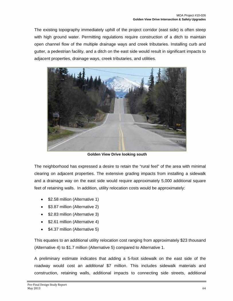
MOA Project #10-026 Golden View Drive Intersection & Safety Upgrades
Pre-Final Design Study Report May 2013 64
The existing topography immediately uphill of the project corridor (east side) is often steep
with high ground water. Permitting regulations require construction of a ditch to maintain
open channel flow of the multiple drainage ways and creek tributaries. Installing curb and
gutter, a pedestrian facility, and a ditch on the east side would result in significant impacts to
adjacent properties, drainage ways, creek tributaries, and utilities.
The neighborhood has expressed a desire to retain the “rural feel” of the area with minimal
clearing on adjacent properties. The extensive grading impacts from installing a sidewalk
and a drainage way on the east side would require approximately 5,000 additional square
feet of retaining walls. In addition, utility relocation costs would be approximately:
• $2.58 million (Alternative 1)
• $3.87 million (Alternative 2)
• $2.83 million (Alternative 3)
• $2.61 million (Alternative 4)
• $4.37 million (Alternative 5)
This equates to an additional utility relocation cost ranging from approximately $23 thousand
(Alternative 4) to $1.7 million (Alternative 5) compared to Alternative 1.
A preliminary estimate indicates that adding a 5-foot sidewalk on the east side of the
roadway would cost an additional $7 million. This includes sidewalk materials and
construction, retaining walls, additional impacts to connecting side streets, additional
Golden View Drive looking south

MOA Project #10-026 Golden View Drive Intersection & Safety Upgrades
Pre-Final Design Study Report May 2013 65
impacts to adjacent driveways, additional impacts to drainage ways, and additional utility
relocation costs (including a fiber optic line and a pressurized 12-inch gas main on the east
side of the ROW).
With no pedestrian facility on the east side, the side street grades can be a maximum of 4
percent within 30 feet from the edge of Golden View Drive. If a pedestrian facility were
installed on the east side, the roadway grade across the pedestrian access route can only
be a maximum of 2 percent.
Therefore, it is recommended that a pedestrian facility only be installed on the west side
(Alternative 1) to minimize impacts to adjacent properties, wetlands, creeks, drainage ways,
and utilities.
Side Street Intersections/Access Control F.
Kinney Engineering, LLC performed an analysis of side street intersection and access
control to determine if auxiliary turn lanes were warranted at various cross streets. Capacity
analyses at the major cross-street intersections indicate that auxiliary turn lanes are not
required to achieve adequate LOS. Using AASHTO’s guidelines for determining turn lanes
at intersections, left turn lanes are recommended at E. 156th Avenue, Goldenview Middle
School driveway, and Prominence Pointe Drive.
Due to impacts to adjacent streams, wetlands, terrain, and private property associated with
adding additional width to the roadway, construction of auxiliary turn lanes is not practical.
Adequate LOS can be achieved without left turn lanes; therefore, left turn lanes are not
recommended at E. 156th Avenue, Goldenview Middle School driveway, or Prominence
Pointe Drive. Additionally, the current configuration of Goldenview Middle School’s driveway
allows for “cooperative” or courteous gaps to allow for vehicles to exit or enter the school
during peak hours. If a turn lane were added, the cooperative gaps would most likely not
occur because two lanes of traffic would be required to cooperate simultaneously to allow
for a gap.
Rabbit Creek Road/Golden View Drive Intersection G.
Various alternatives were analyzed for improving the intersection of Rabbit Creek Road and
Golden View Drive. In November 2011, an Intersection Analysis Report was submitted to
ADOT for review (see APPENDIX G for the full Intersection Analysis Report). A meeting was
held with ADOT in December 2011 to discuss the alternatives and proposed improvements
at this intersection.

MOA Project #10-026 Golden View Drive Intersection & Safety Upgrades
Pre-Final Design Study Report May 2013 66
ADOT expects to study and analyze the hillside intersections, including the intersection of
Rabbit Creek Road and Golden View Drive. Although this intersection has an above-
average crash rate, it does not currently have an above-average crash severity rate.
Because of this statistic, combined with the planned Hillside Intersection Study,
improvements to the intersection of Rabbit Creek Road/Golden View Drive are currently on-
hold and are not anticipated to be included with the Golden View Drive project.
Structural Section H.
The MOA’s Design Criteria Manual states that road sections should be designed to minimize
the following: frost penetration into frost susceptible subgrade soil, movement of fine grained
soil into the structural section, and differential frost heaving. These objectives are typically
accomplished by providing either a sufficient thickness of non-frost susceptible (NFS) fill or a
lesser amount of fill combined with insulation. Based on the existing F2-F3 soil along most
of the alignment, it is estimated that 8.5 to 10.4 feet of NFS would be required to limit
subgrade frost penetration to meet the DCM guidelines. If insulation is used to provide frost
protection, the overall thickness of NFS fill may be reduced to approximately 4 feet. The
insulation should extend beyond the back of curb a minimum of 2 feet to limit lateral frost
penetration. Additionally, detailed consideration needs to be given to the transition between
insulated sections and non-insulated sections, such as at the beginning and end of the
insulated section, as well as at the side streets and driveways. The insulation needs to be
transitioned to minimize differential heaving that can occur at the division between insulated
and non-insulated sections. Appropriate transitions can include extending the insulation
beyond the roadway improvements, reducing the insulation thickness, or angling the
insulation downward.
Use of a frost tolerant section, an alternative to the insulated section, may be warranted
where subgrade soil has low to moderate frost susceptibility or where groundwater is
relatively deep and subgrade soil is not saturated most of the year. A frost tolerant section
could be considered at the beginning of the project, from approximate station 508+00 to
about station 520+00. Soil borings in this area encountered shallow weathered rock,
between 2.5 feet to 12 feet below ground surface. A frost tolerant section may also be
considered at the north end of the project, between approximate stations 590+00 to 599+50.
General appearance of the pavement surface suggests that roadway performance in this
segment is better than the remainder of the alignment. A frost tolerant section in these two
segments would consist of approximately 2.25 feet of NFS fill material.

MOA Project #10-026 Golden View Drive Intersection & Safety Upgrades
Pre-Final Design Study Report May 2013 67
Example rock-gabion retaining wall Example modular block retaining wall
For both an insulated and frost tolerant section, a non-woven geotextile is included along the
base of the structural section to separate the native silty subgrade materials from the
imported subbase fill.
When peat is exposed in the base of the excavation, it is recommended that the peat be
excavated out and replaced with imported fill.
Retaining Walls I.
Due to the steep adjacent terrain along the project corridor, retaining walls will be required to
reduce the impacts from roadway grading and slopes. Retaining walls should be installed as
needed to minimize impacts to utilities, the environment, and adjacent properties.
1. Retaining Wall Types
Below is a description of the four basic types of retaining walls along with their
characteristics.
Gravity: Gravity retaining walls rely on the mass of the wall structure for stability. The
wall mass must be sufficient to counteract sliding and overturning forces from the
retained soil. These systems can use stone, concrete or other heavy material as well as
mechanically stabilized earth (MSE) for stability. These are the most common type of
reretaining walls and include gabions, bin walls, and modular block concrete
construction. In most cases the slope behind the wall needs to be temporarily removed
during construction. For mechanically stabilized earth walls, the reinforcing often extends
horizontally into the embankment about as far as the exposed wall face is tall.

MOA Project #10-026 Golden View Drive Intersection & Safety Upgrades
Pre-Final Design Study Report May 2013 68
Piling: Piling retaining walls have structures that extend significantly below grade to
provide support to counteract horizontal forces from the retained soils. Typically two
thirds of the structure height is embedded below grade. The structures are usually steel
sheet piles or H beams. Piles are driven into the soil while H beams can either be driven
in or set into drilled holes. Quite often, the structural face of a piling wall is covered with
a facade of concrete blocks or panels. These are some of the most expensive types of
retaining walls but they do allow construction with very little removal of soil behind the
wall.
Cantilever: Cantilever retaining walls have a large effective mass due to the soil placed
over a horizontal section of the wall. These walls are typically constructed of cast-in-
place, reinforced concrete. The horizontal (cantilevered) leg of the structure can either
extend back into the retained soil or out away from the slope. The slope behind the wall
typically needs to be temporarily removed during construction. Cantilever walls are
relatively expensive due to the work required to build concrete forms, install reinforcing,
pour concrete, and provide joints between pours. The concrete needs ample time to cure
before the soil can be replaced behind the wall.
Anchored: Anchored (or tieback) retaining walls use cables driven horizontally into the
soil to counteract opposing horizontal forces from the retained soils. The anchors, which
typically pull horizontal plates or sheets against the soil, can be soil nails, tieback cables,
or screw anchors. The soil behind the wall does not need to be removed during
construction. The anchors may need to extend into the embankment quite a ways,
which can impact buried utilities or future development.
Combination: Many retaining walls use a combination of the above types. For example,
many piling walls use anchors to reduce embedment depth and structure strength.
2. Considerations
The decision to construct a retaining wall can be subjective and must balance the cost of
installing a retaining wall with the overall impacts to utilities, wetlands, the environment,
or adjacent properties. Impacts to wetlands often demand construction of retaining walls
due to permitting requirements to avoid or minimize wetlands impacts if possible. Exact
locations of retaining walls will require further refinement during the design phase. Below
are important considerations that affect the decision to provide a retaining wall and
which type of wall should be constructed.

MOA Project #10-026 Golden View Drive Intersection & Safety Upgrades
Pre-Final Design Study Report May 2013 69
Embankment Impacts: Gravity and cantilever retaining walls typically require some of the
soil behind the wall to be temporarily removed during construction. In some cases the
slope can be cut to stand near vertical for short periods of time to reduce impacts but
OSHA embankment guidelines and worker safety must be accounted for. Piling walls
can minimize impacts to adjacent properties and structures.
Foundation Soils: Gravity and cantilever retaining walls require a solid foundation to
resist the forces of the wall and soil. Where foundation soils are weak, a piling or anchor
wall should be considered or the weak soil replaced. The bedrock encountered near the
south end of the Golden View Drive project provides an excellent foundation but makes
driving sheet piles very difficult (see APPENDIX E for the geotechnical report).
Groundwater/Drainage: Groundwater needs to be removed from behind the retaining
wall to reduce hydrostatic forces. Many types of wall are inherently porous while other
Basic types of retaining walls

MOA Project #10-026 Golden View Drive Intersection & Safety Upgrades
Pre-Final Design Study Report May 2013 70
types, like reinforced concrete, require weep holes to be integrated into the design to
relieve pressure from water behind the wall. In areas where substantial groundwater and
glaciation is expected, a subdrain should be considered to direct the runoff to drainage
ditches or a piped storm drain collection system.
Utilities: Some types of retaining walls impact a considerable amount of soil behind the
face of the wall. For example, modular block walls and MSE walls rely on reinforcing
geotextile fabric embedded into the soil as part of the structure. The fabric behind the
wall can impact existing utilities or limit future placement of utilities. Anchor wall cables
also extend into surrounding soils and affect utilities.
Aesthetics: Retailing walls are often very noticeable along a roadway corridor and they
should be selected to compliment the landscaping design and blend in with the
surrounding neighborhood. Sometimes retaining walls are chosen to match existing
walls on adjacent properties. Many of the existing retaining walls along Golden View
Drive are large irregular boulders. Although many PM&E roadway project use concrete
modular block retaining walls, gabion walls may be more appropriate for this project area
where residents have expressed a desire to retain the “rural feel”. Gabion walls have
also been used in other Anchorage hillside areas including along Birch Road and for
South Anchorage High School.
Safety Fence or Handrail: When the
vertical face of the retaining wall is more
than 2.5 feet tall, a fence, handrail, or
guardrail should be provided for safety.
Moose should be discouraged from
walking over the wall. Where space is
limited, a fence or handrail can be
placed near the face of a reinforced
concrete wall. Most other types of wall
require the fence to be set back in the
soil behind the wall.
Construction Schedule: In some cases, the amount of time required to construct a
retaining wall is very important since it can affect impacts to adjacent property owners or
the environment. Reinforced concrete headwalls take a considerable amount of time to

MOA Project #10-026 Golden View Drive Intersection & Safety Upgrades
Pre-Final Design Study Report May 2013 71
Construction of gabion-type retaining wall
construct. They are typically not a good
option for stream culvert headwalls that
need to be completed quickly to reduce
environmental impacts.
Maintenance: Retaining walls and
associated fences or handrails should
be designed to require little if any
maintenance. Concrete surfaces can
be provided with coatings to facilitate
removal of spray paint vandalism.
Cost: The estimated installed cost for
retaining walls varies considerably from
$45 to more than $200 per square foot
of the exposed vertical face. Some of
the biggest factors include soil
conditions, wall height, tiebacks,
construction access, type of fence and
the amount of soil to be removed
behind the wall for construction. On the
following page is a summary of order-
of-magnitude cost for various types of
retaining walls for comparison
purposes. These costs include a chain
link fence above the wall.
Example modular block retaining wall with railing
Construction of modular block retaining wall

MOA Project #10-026 Golden View Drive Intersection & Safety Upgrades
Pre-Final Design Study Report May 2013 72
Summary of Unit Costs
Retaining Wall Type Cost per
Square foot of wall face, installed
Excavation
Modular block (Keystone), without tiebacks $45 full excavation behind blocks,
limited to 4' height
Modular block (Keystone), geogrid tiebacks $60 full excavation behind geogrid
Mechanically Stabilized Earth (MSE) $75 with concrete face, full excavation
behind wall and tieback
Gabion Basket $75 full excavation behind wall
Reinforced concrete, cast-in-place $120 full excavation behind base of
structure
Soldier pile, without tiebacks $130 with block facade, minimal
excavation behind wall
Soldier pile, with tiebacks $190 with block facade, minimal excavation behind wall
Sheet pile, without tiebacks $180 with block facade, no excavation behind wall
Sheet pile, with tiebacks $210 with block facade, no excavation behind wall
3. Estimated Project Cost
The conceptual drawings located in APPENDIX B indicate where retaining walls should be
considered to limit impacts to utilities, the environment or adjacent property. The
potential areas for retaining walls for the preferred alternative (Alternative 1) are
summarized below in TABLE 6. Note: this summary does not include stream culvert
headwalls.

MOA Project #10-026 Golden View Drive Intersection & Safety Upgrades
Pre-Final Design Study Report May 2013 73
Table 6 – Summary of Retaining Walls (preferred alternative)
Purpose
Street Approx.
Start Station
Off-set
Ave Height
(ft) Length
(ft) Area (sf) Utility Environ-
ment Property
Golden View 528+75 Left 4.9 181 887 X
Golden View 531+27 Right 3.5 108 378 X X
Golden View 535+34 Right 5.2 28 146 X
Golden View 541+27 Right 6.4 285 1,824 X X
Golden View 543+88 Left 2.5 65 163 X
Golden View 544+69 Left 2.0 107 214 X
Golden View 546+45 Left 3.0 296 888 X
Golden View 549+72 Right 4.0 667 2,668 X X
Golden View 568+81 Right 3.4 116 394 X Golden View 570+69 Left 3.5 572 2,002 X X Golden View 577+45 Left 2.5 542 1,355 X Golden View 584+65 Left 4.5 530 2,385 X
Romania 200+78 Left 4.1 38 156 X
A modular block or gabion basket type retaining wall can be used in nearly all of the
areas identified above. Assuming a unit cost from $60 to $75 for modular block and
gabion basket wall types respectively, this represents an approximate cost of $880
thousand to $1.01 million for the recommended Alternative 1.
Traffic Calming J.
Based on speed studies and comments from local residents, speeding is a concern.
Various methods for traffic calming were investigated, including:
• Vertical traffic calming measures (ex. speed hump)
• Horizontal traffic calming measures (ex. neckdowns)
• Full or partial closures
• Center islands narrowing
• Colored crosswalks
• Roadway striping
Due to the vertical curves and steep grades along Golden View Drive, locations for vertical
or horizontal traffic calming measures are limited. Speed humps and neckdowns are most

MOA Project #10-026 Golden View Drive Intersection & Safety Upgrades
Pre-Final Design Study Report May 2013 74
appropriate on flat, straight roadways with less than 30 MPH posted speeds. Speed humps
are also discouraged on collector roadways and are not recommended on primary
emergency routes or bus routes. Golden View Drive is the primary route into and out of
many of the adjacent neighborhoods and speed humps significantly reduce the response
time of emergency vehicles. Traffic calming features that significantly reduce traffic volumes,
like diverters and partial or full-closures are not appropriate on collector roadways. These
measures tend to divert traffic onto adjacent residential streets and reduce the efficiency of
the transportation system.
Roadway striping will be installed along the entire project corridor, including shoulder
stripes, which will effectively reduce the visual appearance of the travel lane widths. The
visual appearance of narrower lanes, as compared to feeling comfortable utilizing the entire
roadway surface, reduces traffic speed. Shoulder stripes can also serve a dual purpose by
designating the shoulder as a bike lane and reducing the visual dimensions of the travel
lane. Existing short vertical curves also serve as traffic calming measures.
Lighting K.
The DCM’s lighting requirements are based on the IESNA RP-8-00 American National
Standard Practice for Roadway Lighting.
• Golden View Drive is designated as a collector for lighting standards in the IESNA
(Section 2.1).
• The IESNA does not make recommendations or provide guidelines for partial lighting
of intersections only (Section 1.1). It only provides recommendations “for designing
continuous lighting systems for roadways.”
• Transition lighting is recommended in the IESNA to provide a driver with gradual
reduction in lighting levels when leaving a lighting system. As an example, if only the
intersections along Golden View Drive were illuminated, transition lighting should be
installed along the roadway to gradually adjust the driver’s eye to the intersection
lighting levels. The transition lighting would most likely extend to the adjacent
intersections, resulting in continuous roadway lighting.
• Several studies have also shown that the primary benefit of lighting intersections along
major streets is a reduction in night pedestrian, bicycle, and fixed object crashes
(Section 3.6.2) and proper intersection lighting is a critical design component.
Intersections should be illuminated to increase safety.

MOA Project #10-026 Golden View Drive Intersection & Safety Upgrades
Pre-Final Design Study Report May 2013 75
Example of the white light from LEDs
To reduce the length of the vertical curves along the roadway profile, lighting is required for
visibility and sight distance. If lighting were not installed, the vertical curves would be
significantly longer and result in a wider roadway footprint, thus the impacts to adjacent
properties, wetlands, drainage ways, and utilities would also be significantly larger.
The new lighting system will need to achieve the
light levels and uniformity ratios required for a
collector roadway, including the pathways and
intersections. The system will include rounded
steel poles that provide a 30 to 40-foot luminaire
mounting height and include tapered mast arms
that locate the luminaires in the positions
determined by the lighting analysis. Per Chapter
5 of the DCM, along roadways with posted
speeds of 40 MPH or greater, poles shall have
breakaway bases. In urban areas were speeds
are between 30 and 40 MPH, luminaire pole bases may be breakaway or non-breakaway. In
selecting breakaway versus non-breakaway bases, consideration should be given to
balancing the hazards to pedestrians and vehicles from falling (breakaway) poles versus the
impact on a vehicle and its occupants with a non-breakaway base.
The system also will include light emitting diode (LED) luminaires that provide a full cutoff
light distribution. The poles are to be located on property corners, where feasible, to reduce
the light trespass into adjacent homes. Light levels and uniformity ratios on collector road,
pathways, and at the intersections are summarized below:
• Road: The DCM recommends a minimum maintained average of 0.6 foot-candles
with an average-to-minimum uniformity ratio no greater than 4:1 and a veiling
luminance ratio no greater than 0.4.
• Pedestrian Facilities: Pedestrian activity along Golden View Drive meets the “low”
criteria provided in Chapter 5 of the DCM. For adjacent pedestrian facilities within the
low pedestrian volume criteria, Chapter 5 of the DCM includes three light level
requirements based on land use: rural/semi-rural, low-density residential, and medium-
density residential. In areas with single family homes (low-density residential), a
minimum maintained average of 0.3 foot-candles with an average-to-minimum
uniformity ratio no greater than 6:1 is required.

MOA Project #10-026 Golden View Drive Intersection & Safety Upgrades
Pre-Final Design Study Report May 2013 76
• Intersections: For the purpose of lighting intersections, the DCM uses the following
roadway classifications (note these do not apply to standard street classifications):
o Major: over 3,500 ADT
o Collector: 1,500 to 3,500 ADT
o Local: 100 to 1,500 ADT
For the design year, Golden View Drive north of Bluebell Drive is functionally classified as a
Major road for analyzing intersection lighting. South of Bluebell Drive, Golden View Drive is
a Collector road. For the design year, all side streets are classified as Local roads, except E.
156th Avenue which is classified as a Collector road for intersection lighting. Below is a
summary of intersection lighting requirements from the DCM:
Illuminance for Intersections*
Functional Classification
Average Maintained Illuminance (low pedestrian area)
Maximum Uniformity Ratio
Major/Major 1.8 3.0
Major/Collector 1.5 3.0
Major/Local 1.3 3.0
Collector/Local 1.0 4.0
*From DCM Table 5-5
Landscaping L.
The overall goal of the landscape design is to limit impacts to existing vegetation where
feasible and provide new landscaping where space allows. The width of existing ROW is
primarily 60 feet and can accommodate road, pedestrian, and drainage improvements but
provides little to no additional room for new landscape improvements. The project design will
strive to protect existing mature trees on private property that are adjacent to the proposed
improvements.
Vertical landscaping elements that are installed adjacent to the roadway can act as traffic
calming measures as they provide visual cues to drivers to reduce speeds. These cues can
consist of planters, lighting, or even sculptural elements. It is important that vertical elements
do not impede visibility of pedestrians or vehicles and any such elements are to be installed
in such a way that they are compatible with maintenance needs, such as snow removal and
storage.

MOA Project #10-026 Golden View Drive Intersection & Safety Upgrades
Pre-Final Design Study Report May 2013 77
Native vegetation near Goldenview MS
The use of neighborhood gateways has
become a common way to add interest to
streetscapes, provide neighborhoods with
a unique identity, and provide visual clues
to drivers that they are entering a
neighborhood. They have been very
successful in some neighborhoods and
less so in others. Typically, the gateway
features are most successful in
neighborhoods that already possess a
strong individual identity within their
community. Prominence Pointe subdivision currently has a gateway feature at the
intersection of Prominence Pointe Drive and Golden View Drive.
Native topsoil may be stripped and stockpiled from areas where construction is to take place
within the project alignment. Stockpiled native topsoil can be reused and takes advantage of
the valuable native seed stock within it. Reuse of native topsoil is an effective way to re-
vegetate with native plants without importing large amounts of non-native topsoil. Importing
non-native topsoil can be costly and it can introduce invasive plant species to an area
unnecessarily.
Trails M.
Trail easements have been identified at two locations along the project alignment. One
easement is located at Little Rabbit Creek between parcels 133 and 133A. The other is
located on parcel 172. Even though trails do not currently exist at these locations, it is
intended that access to them be maintained as a part of the project so that future trail heads
will not be impeded. This adheres to the Hillside District Plan’s Chapter 2, Goal 6 of
maintaining, supplementing and enhancing a system of parks, trails, open spaces and other
active and passive recreation areas.

MOA Project #10-026 Golden View Drive Intersection & Safety Upgrades
Pre-Final Design Study Report May 2013 78
Cluster Mailboxes N.
Cluster mailboxes are desirable to
the MOA and the United States
Postal Service as they facilitate
maintenance, reduce delivery times,
and provide a secure receptacle for
the residents. The existing cluster
mailboxes located at the south end
of the project (across from Moen
Park) and at the north end of the
project (near E. 156th Avenue) are to remain. At this time, there are no plans to replace the
existing single-serve mailboxes with cluster boxes.
Parking O.
Golden View Drive is designated as a residential collector, which emphasizes a higher
degree of mobility than access to adjacent properties. Given the large lot size of adjacent
properties, with generally longer driveways and parking pads, combined with the emphasis
on mobility along Golden View Drive, on-street parking is not recommended.
Cluster mailboxes on Golden View Dr., south of E. 156th

MOA Project #10-026 Golden View Drive Intersection & Safety Upgrades
Pre-Final Design Study Report May 2013 79
VII. Drainage Analysis
Existing Planning Documents A.
The planning document Pilot Watershed Drainage Plan for Little Rabbit Creek and Little
Survival Creek Watersheds – December 2008 (WDP) includes watershed characterization,
runoff modeling, and recommendations for drainage infrastructure improvements and runoff
controls. Policy recommendations are also presented to promote watershed-wide drainage
management. It is a goal of this project to implement recommendations made in the
Watershed Drainage Plan within the Golden View Drive ROW.
Storm Water Model B.
A storm water model was assembled and computed to determine size and location of
drainage facilities along Golden View Drive. As part of the drainage analysis effort, the peak
discharge was calculated at key locations to properly size storm drain piping, catch basins
and other storm drainage appurtenances for both the existing and proposed conditions.
Additionally, analysis results were compared to those of the WDP to verify agreement with
conveyance structure sizes. The drainage analysis approach is consistent with industry
standards and the MOA PM&E DCM and accompanying Drainage Design Guidelines.
Supporting data and modeling for the drainage analysis is found in APPENDIX F.
The existing and proposed storm drainage systems have been modeled with Bentley
CivilStorm V8 computer modeling software. The peak stormwater discharge was determined
for both conditions. The SCS Curve Number method was used to develop rain-runoff
response. As published in the MOA PM&E DCM, the SCS Type I, 10-year, 24-hour duration
storm distribution was modeled for peak discharge conveyance design. Additionally, peak
storm water discharge for the SCS Type I, 2-year, 24-hour storm event was analyzed for
storm water treatment purposes. Based on the location of the project area, orographic
factors varying from 1.30 to 2.13 has been applied to adjust the 1.77-inch and 1.26-inch
base storm volumes for conveyance and water treatment design, respectively. Storm event
data and drainage analysis input parameters are found in APPENDIX F.
The drainage basins were further refined and adjusted from GIS data obtained from MOA
Information Technology Department and WMS. The computer software ArcMap by ESRI
was used to view and analyze GIS data in conjunction with aerial imagery to determine
impervious areas, slope and land cover. Once the basin data was compiled from ArcMap,

MOA Project #10-026 Golden View Drive Intersection & Safety Upgrades
Pre-Final Design Study Report May 2013 80
Microsoft Excel was used to compute the necessary input parameters required for both the
existing and proposed CivilStorm drainage models.
The storm water runoff generated from each subbasin is summarized below in TABLE 7. For
modeling and analysis purposes, undeveloped areas have been considered fully developed
to ensure the proposed drainage improvements are sized to convey increased future storm
runoff.
Table 7 – Summary of storm water runoff
Subcatchment Area 1-yr 24-hr 10-yr 24-hr
UNIT (Acre) (cfs) (cfs/AC) (cfs) (cfs/AC) B101 23 0.3 0.02 4.7 0.21 B102 9 0.1 0.01 1.8 0.08 B103 3 0.3 0.12 1.3 0.06 B104 33 0.6 0.02 6.0 0.27 B105 5 0.5 0.09 2.2 0.10 B106 39 0.8 0.02 8.5 0.38 B107 3 0.4 0.11 1.3 0.06 B108 36 1.3 0.04 9.9 0.44 B109 1 0.4 0.69 0.9 0.04 B110 51 1.3 0.02 10.0 0.44 B111 55 8.2 0.15 26.3 1.16 B112 4 1.2 0.31 3.4 0.15 B114 22 12.6 0.56 27.0 1.19 B115 20 1.7 0.08 8.5 0.38 B116 8 2.1 0.25 6.2 0.28 B117 94 14.6 0.16 44.5 1.97 B118 5 1.0 0.21 3.0 0.13 B119 58 2.6 0.05 16.9 0.75 B120 123 2.5 0.02 22.9 1.01 B400 229 33.1 0.14 114.6 5.07 B401 88 3.8 0.04 31.3 1.38 B402 60 3.7 0.06 21.2 0.94 B403 29 2.3 0.08 11.4 0.51 B404 62 2.4 0.04 18.5 0.82

MOA Project #10-026 Golden View Drive Intersection & Safety Upgrades
Pre-Final Design Study Report May 2013 81
Proposed Drainage System C.
The proposed drainage system is made up of five separate systems, each with their own
outfall. Site topography and existing stream and drainages necessitates using separate
systems. Common to each system is use of typical CPEP piping, catch basins and catch
basin manholes for storm drain mains. Stream crossings larger than approximately 4 feet in
diameter may be concrete, aluminum, or steel structures as determined during detailed
design. Existing roadside ditches and drainage ways on the east or uphill side of Golden
View Drive will be maintained or reconstructed. Side street ditches will be installed and/or
improved where streets are being modified. At cases where ditch grades are relatively
steep, permanent ditch armoring will be constructed for erosion protection. The five systems
are described below, start at the southern end of the project.
System 1
System 1 extends generally from station 508+00 near Romania Drive to station 514+60.
The flow direction is from north to south. This system collects primarily roadway runoff
and consists of standard catch basins and catch basin manholes. The existing culvert
crossing at the intersection of Golden View Drive and Romania Drive which carries the
Potter Branch (refer to “Stream Crossings” table) drainage will be replaced and
incorporated into this system. A treatment facility will be incorporated into the system prior
to discharge. Based on limited availability of land and challenging topography, the
treatment facility will likely be a vault-type treatment unit.
Conceptual graphic of a culvert crossing

MOA Project #10-026 Golden View Drive Intersection & Safety Upgrades
Pre-Final Design Study Report May 2013 82
System 2
System 2 extends from station 518+00 to station 522+10. The flow direction is from south
to north. This system collects roadway runoff. The existing culvert crossing at station
522+10 which carries the South Fork Little Survival Creek drainage will be replaced. A
treatment facility will be incorporated into the system prior to discharge. Based on limited
availability of land and challenging topography, the treatment facility will likely be a vault-
type treatment unit.
System 3
System 3 extends from station 526+40 to station 531+50 just north of Bluebell Drive. The
flow direction is from the south and north to the stream crossing at station 529+30. The
existing culvert crossing at station 529+30 which carries the South Branch Little Survival
Creek drainage will be replaced. Runoff from the lower portion of Bluebell Drive will be
collected by this system. This includes both runoff from the roadway and also roadside
ditches. A treatment facility
will be incorporated into the
system prior to discharge.
Based on limited availability of
land and challenging
topography, the treatment
facility will likely be a vault-
type treatment unit. A
diversion structure or typical
manhole will be used to outfall
treated roadway runoff into the
natural drainage.
System 4
System 4 extends from station 533+00 to station 534+70. The flow direction is from south
to north. This system collects roadway runoff. The existing culvert crossing at station
535+70 which carries Little Survival Creek will be replaced. A treatment facility will be
incorporated into the system prior to discharge. There may be an opportunity to install a
small natural treatment system East of Goldenview Drive between the outfall at 534+75
and the creek culvert at station 535+70.
Conceptual graphic of a roadside ditch

MOA Project #10-026 Golden View Drive Intersection & Safety Upgrades
Pre-Final Design Study Report May 2013 83
System 5
System 5 extends from station 536+85 to station 595+40. The flow direction is from south
to north. This system collects roadway runoff and also serves as a bypass system to route
flood flows to Little Rabbit Creek via a large diameter storm drain main. A treatment facility
will be incorporated into the system prior to discharge at Little Rabbit Creek.
Three diversion structures will serve as bypass metering facilities to maintain flow to North
Branch Little Survival Creek, South Branch South Fork Little Rabbit Creek, and North
Branch South Fork Little Rabbit Creek. These structures will be designed so that regular
stream flows are allowed to cross Golden View Drive and bypass large runoff events into
the storm drain main. Adjustable stop gates, weirs, or valves are proposed to allow for
flow adjustments. Simple flumes may be incorporated to facilitate flow measurements.
Specific base flow rates for each drainage are still being negotiated with the USACE.
Little Rabbit Creek Crossing
Little Rabbit Creek is crossed by Golden View Drive at station 595+60. The existing 72-
inch x 48-inch culvert has a perched outlet due to a considerable scour hole and does not
meet fish passage criteria. This structure will be removed and replaced with a new
structure as part of the roadway reconstruction. Roadway improvements are expected to
increase in width and thus may necessitate a longer structure. New installations of this
size are typically a structural plate box culvert, also known as a multi-plate culvert. Other
options should be evaluated in design based on depth of bury, stream grade, final
roadway grade and width, and FEMA requirements for flood flow passage.
Treatment Facilities
Stormwater treatment facilities are incorporated into the storm drain design to minimize
potential water quality impacts to surrounding area watersheds. The design of the
treatment facilities are based on the requirements of PM&E and ADEC. Overland
discharge through a bio-swale is considered as the first option for stormwater treatment. If
the bio-swale is not considered an acceptable treatment method, an oil/grit separator,
such as those manufactured by Stormceptor, Contech, or AquaShield, could be required
for stormwater treatment.

MOA Project #10-026 Golden View Drive Intersection & Safety Upgrades
Pre-Final Design Study Report May 2013 84
VIII. Right-of-Way Impacts
Overview A.
A key element for the successful completion of this project is the acquisition of any required
ROW, easements and/or permits while providing fair and equitable treatment to all affected
property owners, tenants and lessees. Fee acquisitions and easements facilitate the
construction of roadway and pedestrian amenities and associated utility relocations.
The MOA has the authority to acquire private property for public projects. A primary goal of
ROW acquisition is to acquire property rights from willing sellers through good-faith
negotiations in accordance with all pertinent policies, statutes, laws and regulations while
treating all owners equitably. The necessity of the project and the selection of one
alternative over others must be carefully considered and demonstrate that “the property is
taken by necessity for a project located in a manner which is most compatible with the
greatest public good and the least private injury.” AS 09.55.430(7). Property owners are
entitled to receive just compensation for any property rights acquired. Displaced owners and
tenants are entitled to displacement or relocation benefits. When owners are unwilling (or
perhaps unable) to sell and property rights acquisition is demonstrated to be necessary for
public projects, the MOA has the authority to acquire property through its right of eminent
domain (ED). Condemnation is the process of exercising the right of ED and is prescribed
by MOA code and state law.
In general, public use easements (PUE) are required in areas where the footprint of the
improvements exceeds the ROW. Slope easements (SE) are required for areas where the
cut and fill slopes are outside of the ROW. Storm drain easements (DE) are required for
drainage facilities installed on private property. Temporary construction permits (TCP) are
required on private properties for matching new driveway grades to existing driveway
grades, installation of storm drain footing services or water key boxes at the property line,
and the relocation, removal or repair of improvements such as mailboxes, curbs,
landscaping, fencing, and encroaching structures. Temporary construction easements (TCE)
allow contractors temporary access onto private property to construct improvements that are
within the ROW but where there is insufficient space within the ROW to conduct the work.
In addition to the easements and permits, rights of entry are obtained from property owners
to allow access to private properties for the purposes of soils testing, surveying activities
and/or data gathering.

MOA Project #10-026 Golden View Drive Intersection & Safety Upgrades
Pre-Final Design Study Report May 2013 85
Property owners who have personal improvements in the ROW, such as fences, retaining
walls or landscaping boulders, have the option of applying for encroachment permits for the
improvements, removing them at their own expense, or allowing the corrective action be
incorporated into the project design. Encroachment permits for fences, rock gardens,
planters, and decorative retaining walls within 7 feet of back of curb are usually not granted.
Right-of-Way Easements/Permits B.
The existing dedicated ROW for Golden View Drive varies from 60 feet to 200 feet in width.
The majority of the ROW was dedicated to the MOA by subdivision plat as the properties
were subdivided. The exception to this is three un-subdivided parcels or tracts adjacent to
Golden View Drive that have 33-foot section line road reservation easements instead of
road dedications. These properties include Tract 1 of Viewpoint Subdivision, the un-
subdivided parcel north and adjacent to Block 7 of Paradise Valley Subdivision and the un-
subdivided parcel north and adjacent to Lot 2 of Jeffers Subdivision. In addition to these
three parcels, there are additional parcels that have dedicated ROW but are still affected by
a 33-foot or 50-foot wide section line easement or a road reservation that was included in
the original land patent from the federal government. These parcels have additional ROW
that can be used for the project. Although, since the underlying lands within the section line
easements are owned by the property owner, fences and other items that meet municipal
code may be constructed within the easements or along the property lines before or after
the project is completed.
Estimated easement requirements are summarized in TABLE 8 below and detailed in
APPENDIX H. As the planning and design of this project progresses, the required
construction permits, easements, or property acquisitions will be refined.
Table 8 – Estimated Right-of-Way Easements/Permits
Drainage Easement (DE) 6
Slope Easement (SE) 38
Temporary Construction Permit (TCP) 21
Public Use Easements (PUE) 1

MOA Project #10-026 Golden View Drive Intersection & Safety Upgrades
Pre-Final Design Study Report May 2013 86
IX. Design Recommendations The plan and profile drawings for the proposed roadway improvements can be found in
APPENDIX B.
Roadway A.
The horizontal alignment of Golden View Drive follows the existing roadway centerline. It is
recommended that the existing horizontal radii of adjacent local side streets remain as
currently constructed.
The proposed vertical profile generally follows the existing roadway grade but varies higher
or lower than existing ground near side street intersections to reduce impacts to the steep
adjacent local side streets. It is recommended to raise the vertical roadway profile of
Golden View Drive near Bluebell Drive by approximately 1.5 feet. The maximum grade on
Golden View Drive is 10.0 percent. The proposed grade for Ransom Ridge Road will most
likely require a design variance and thus will be refined during the design phase.
The proposed cross section consists of two 11-foot lanes with 3.5-foot shoulders and barrier
curb and gutter. A single, ADA compliant pedestrian facility is recommended: an 8-foot wide
paved pathway located on the west side, separated from the back of curb where feasible.
During design, there may be additional locations to detach the pathway with minimal
impacts. A drainage ditch would be located on the east side.
A phased construction approach is recommended along the project corridor to
accommodate the large project area.
Structural Section B.
Roadway insulation is recommended in the structural section to minimize excavation,
structural fill, and frost penetration.
Retaining Walls C.
Retaining walls are recommended, as appropriate, to minimize impacts to adjacent utilities,
properties, or the environment. Retaining walls should be gabion style or modular block to
best compliment the surrounding landscape and neighborhood.

MOA Project #10-026 Golden View Drive Intersection & Safety Upgrades
Pre-Final Design Study Report May 2013 87
Drainage D.
The proposed drainage system is made up of five separate systems, each with their own
outfall. Site topography and existing stream and drainages necessitates using separate
systems. Common to each system is use of typical CPEP piping, catch basins and catch
basin manholes for storm drain mains. Stream crossings larger than approximately 4 feet in
diameter may be concrete, aluminum, or steel structures as determined during detailed
design. Existing roadside ditches and drainages on the east or uphill side of Golden View
Drive will be maintained or reconstructed. Side street ditches will be installed and/or
improved where streets are being modified. At cases where ditch grades are relatively
steep, permanent ditch armoring will be constructed for erosion protection.
A large diameter storm drain main will extend along a majority of the project length, serving
as both a roadway runoff collection system, and high runoff bypass system. Diversion
structures will be installed to maintain existing stream flows and meter bypass flows to the
main and on to Little Rabbit Creek. Existing stream and drainage crossing structures will be
replaced and upgraded as required by modifications to the roadway cross section.
A permeable road base cross section is proposed for three locations at existing wetlands
adjacent to Golden View Middle School. The permeable road base will help distribute
subsurface and mixed surface flows to the wetlands, with the goal of reducing
channelization, concentration of base flows, and subsequent icing.
Electrical thaw systems will be installed at culverts, treatment and diversion structures, and
other icing-susceptible locations within the proposed storm drain system. Culvert crossings
will incorporate freeze-reduction features, such as insulation and underflow drain rock.
Traffic Calming E.
Traffic calming measures consist of double-yellow centerline striping and 4-inch shoulder
striping. The shoulders would also include “Bike Lane” symbols.
Lighting F.
A continuous roadway LED lighting system, current with MOA standards, is proposed.
Landscaping G.
Proposed landscaping will be in character with the adjacent residential properties. The focus
will be on preserving existing vegetation to the greatest extent practical, with new plantings
supplementing or possibly replacing the those disturbed by construction. No new plantings

MOA Project #10-026 Golden View Drive Intersection & Safety Upgrades
Pre-Final Design Study Report May 2013 88
will be placed within the buffer between the roadway and the pathway; this area is to receive
topsoil and seed.
Restoration of streams and creeks will take place where they are affected by the project.
Restoration will include the use of native plants in order to heal the stream banks and
prevent erosion. Landscape boulders may also be used to restore a stream or creek to its
most natural function and appearance.
Design Cost Estimate H.
A cost estimate for the proposed improvements is presented in summary format below in
TABLE 9. A more detailed cost breakdown is found in APPENDIX I. It should be noted that the
estimates shown include a 20 percent construction contingency. Only the recommended
improvements were estimated and include the items summarized in this section. The other
alternatives were not estimated due to the impracticality of carrying these alternatives
forward because of the significant impacts to adjacent private septic systems, ditches,
drainage ways and stream tributaries, driveways, properties, retaining walls, and utilities.
Table 9 – Summary of Estimated Construction Costs
Schedule Total
Roadway & Sidewalk Improvements1 $9,114,000
Storm Drainage Improvements $4,877,000
Illumination and Electrical Improvements $1,432,000
Landscaping $480,000
Subtotal Construction = $15,903,000
Contingency (20%) $3,181,000
Total Construction = $19,084,000
Utility Relocation $2,582,000
ROW Acquisition $100,000
Total = $21,766,000 Notes: 1. Estimated costs do not include improvements to Bluebell Drive. 2. Estimated construction and ROW acquisition costs do not include Rabbit Creek Road / Golden View Drive Intersection as this work will be dependent on the outcome of a future study being done by ADOT.