
Gold Series by Ebtron - WordPress.com · Gold Series by Ebtron ... requirements of ASHRAE Standard...
44
a measurable difference! ® Gold Series Thermal Dispersion Airflow Measurement Technology Model GTx116 Technical Manual Advantage 3 Gold Series by Ebtron Installation, Operation and Maintenance Technical Manual GTx116 “Plug & Play” Transmitters Combination RS-485 and Dual Analog output model: GTC116 Combination Ethernet and Dual Analog output model: GTM116 LonWorks ® output model: GTL116 Data Logger output model: GTD116 Document Name: TM_GTx116_R8A A 3 EBTRON, Inc. 1663 Hwy. 701 S., Loris SC 29569 • Toll Free: 800.2EBTRON (232.8766) • Fax: 843.756.1838 • Internet: EBTRON.com TM_GTx116_R8A LISTED European Union Shipments Part Number: 930-0000 Models GTC116 and GTE116 Models GTC116 and GTM116 BACnet is a registered trademark of ASHRAE. ASHRAE does not endorse, approve or test products for compliance with ASHRAE standards. Compliance of listed products to the requirements of ASHRAE Standard 135 is the responsibility of BACnet International (BI). BTL is a registered trademark of BI.
Transcript of Gold Series by Ebtron - WordPress.com · Gold Series by Ebtron ... requirements of ASHRAE Standard...

a measurable difference!
®
Gold Series Thermal Dispersion Airflow Measurement Technology
Model GTx116Technical Manual
Advantage 3Gold Series by Ebtron
Installation, Operation and Maintenance Technical Manual
GTx116“Plug & Play” Transmitters
Combination RS-485 and Dual Analog output model: GTC116
Combination Ethernet and Dual Analog output model: GTM116
LonWorks® output model: GTL116
Data Logger output model: GTD116
Document Name: TM_GTx116_R8A
A3
EBTRON, Inc. 1663 Hwy. 701 S., Loris SC 29569 • Toll Free: 800.2EBTRON (232.8766) • Fax: 843.756.1838 • Internet: EBTRON.com
TM_G
Tx11
6_R
8A
LISTED
European Union
Shipments
Part Number: 930-0000
Models GTC116 and GTE116 Models GTC116 and GTM116
BACnet is a registered trademark of ASHRAE. ASHRAE does not endorse, approve or testproducts for compliance with ASHRAE standards. Compliance of listed products to therequirements of ASHRAE Standard 135 is the responsibility of BACnet International (BI).BTL is a registered trademark of BI.

TM_G
Tx11
6_R
8A
a measurable difference!
®
GOLD SERIES GTX116 TRANSMITTER
EBTRON, Inc. 1663 Hwy. 701 S., Loris SC 29569 • Toll Free: 800.2EBTRON (232.8766) • Fax: 843.756.1838 • Internet: EBTRON.com2
a measurable difference!
®
Copyright © 2015, EBTRON ®, Inc.All brand names, trademarks and registered trademarks are the property of their respective owners. Information contained within this document is subject to
change without notice. Visit EBTRON.com to view and/or download the most recent versions of this and other documents.
All rights reserved.
LIST OF EFFECTIVE AND CHANGED PAGES
Insert latest changed pages (in bold text); remove and dispose of superseded pages.Total number of pages in this manual is 44.
Page No Revision * . . . . . . .Description of Change . . . . . . . . . . . . . . . . . . . . . . . . . . . . . . . . . . . . . . . .Date
1-44 . . . . . . . . . . .R8A . . . . . . . . . . . . . . . .All pages revised/updated to reflect Advantage 3 updates . . . . . . . . . . . . . . . . . . . . . . . . . . . . . . . . . . . . . . . .01/21/2015
TM_G
Tx11
6_R
8A
TM_G
Tx11
6_R
8A
a measurable difference!
®
GOLD SERIES GTX116 TRANSMITTER
EBTRON, Inc. 1663 Hwy. 701 S., Loris SC 29569 • Toll Free: 800.2EBTRON (232.8766) • Fax: 843.756.1838 • Internet: EBTRON.com 3
OVERVIEW . . . . . . . . . . . . . . . . . . . . . . . . . . . . . . . . . . . . . . . . . . . . . .5SPECIFICATIONS . . . . . . . . . . . . . . . . . . . . . . . . . . . . . . . . . . . . . . . . .5ADVANCED TECHNOLOGY . . . . . . . . . . . . . . . . . . . . . . . . . . . . . . . . .5GTx116 TRANSMITTER FEATURES . . . . . . . . . . . . . . . . . . . . . . . . . .6ORDERING GUIDE - GTx116 TRANSMITTER . . . . . . . . . . . . . . . . . . .6GTx116 TRANSMITTER INSTALLATION . . . . . . . . . . . . . . . . . . . . . . .7
GTx116 Mechanical Dimensions . . . . . . . . . . . . . . . . . . . . . . .7Power Transformer Selection . . . . . . . . . . . . . . . . . . . . . . . . . .8Connecting Power to the Transmitter . . . . . . . . . . . . . . . . . . . .8Connecting Sensor Probes to the Transmitter . . . . . . . . . . . . .9
GTC116, GTM116 - COMBINATION ANALOG + NETWORK TRANSMITTER SETUP . . . . . . . . . . . . . . . . . . . . . . . . . . . . . . . . . . .10
GTC/GTM116 - ANALOG OUTPUT OUTPUT WIRING AND SETUP . . . . . . . . . . . . . . . . . . . . . . . . . . . . . . . . . . . . . . . . . . . .10GTC116 - RS-485 NETWORK WIRING CONNECTIONS . . . . .10
RS-485 Network Cable Specifications . . . . . . . . . . . . . .10Connecting to an RS-485 Network: . . . . . . . . . . . . . . . .10
GTx116 TRANSMITTER START-UP, INITIALIZATION AND SETUP MENUS . . . . . . . . . . . . . . . . . . . . . . . . . . . . . . . . . . . . . . . . .12
Changing the System of Units - IP (Inch Pound) units or SI (Standard International) Units . . . . . . . . . . . . . . . . . . . . . .12
GTx116 TRANSMITTER CALIBRATION . . . . . . . . . . . . . . . . . . . . . .12GTx116 LCD DISPLAY NOTIFICATIONS . . . . . . . . . . . . . . . . . . . . . .12
Factory Default Menu Settings for GP1 Sensor Probes . . . .13GTx116 CHANGING FACTORY DEFAULT SETUP MENU SETTINGS 14
Setup Menu Options . . . . . . . . . . . . . . . . . . . . . . . . . . . . . . . .14Selecting Actual and Standard Output Measurement Type .14Output Scaling . . . . . . . . . . . . . . . . . . . . . . . . . . . . . . . . . . . . .14Changing the LCD Display from Volumetric Flow CFM to Velocity FPM . . . . . . . . . . . . . . . . . . . . . . . . . . . . . . . . . . . . . . .14Converting the Analog Output Signal from FPM to CFM . . . .14Locking the Configuration Settings . . . . . . . . . . . . . . . . . . . .14
VIEWING SENSOR DATA . . . . . . . . . . . . . . . . . . . . . . . . . . . . . . . . .15Viewing Sensor Data on the Local LCD Display . . . . . . . . . .15Viewing Sensor Data over BACnet or Modbus Networks orthrough the EB-Link Reader . . . . . . . . . . . . . . . . . . . . . . . . . .15Sensor Addressing and Probe Positioning . . . . . . . . . . . . . . .15
Type ‘A’ (2 Connector) Transmitter . . . . . . . . . . . . . . . . .15Type ‘B’ (4 Connector) Transmitter . . . . . . . . . . . . . . . .15
GTC/GTM116 - ALARM FEATURES . . . . . . . . . . . . . . . . . . . . .17Average Alarm (AO2 ASGN=ALRM) . . . . . . . . . . . . . . . . .17Trouble Alarm (AO2 ASGN=TRBL) . . . . . . . . . . . . . . . . . .17No Fault (NO FAULT=HI) . . . . . . . . . . . . . . . . . . . . . . . . .17Alarm Indications . . . . . . . . . . . . . . . . . . . . . . . . . . . . . . .17Low Alarm - “LO ALRM= ON” . . . . . . . . . . . . . . . . . . . . .17High Alarm - “HI ALRM= ON” . . . . . . . . . . . . . . . . . . . . .17Trouble Alarm - “AO2 ASGN=TRBL” . . . . . . . . . . . . . . . .17
GTC/GTM116 - ANALOG OUTPUT TYPE SELECTION AND SETUP . . . . . . . . . . . . . . . . . . . . . . . . . . . . . . . . . . . . . . . . . . .18
GTC/GTM116 - Converting Analog Output Signal Values to Airflow and Temperature . . . . . . . . . . . . . . . .18GTC116 - OUTPUT TEST - Sending a Test Output Signal to the Host Control System . . . . . . . . . . . . . . . . .18
GTC116 - TRANSMITTER SETUP FOR RS-485 NETWORK OPERATION . . . . . . . . . . . . . . . . . . . . . . . . . . . . . . . . . . . . . . . .19
GTC116 - RS-485 Network Options and Communications Menu Settings . . . . . . . . . . . . . . . . . .19GTC116 - Setting Transmitter Termination for RS-485 Network . . . . . . . . . . . . . . . . . . . . . . . . . . . . . . .19GTC116 - Setting RS-485 Network Protocol . . . . . . . . .19GTC116 - Setting Transmitter Address . . . . . . . . . . . . .19GTC116 - Setting Baud Rate . . . . . . . . . . . . . . . . . . . . .19GTC116 - Setting Device Instance Number . . . . . . . . . .19
GTC116 - Resetting Communications Options to Factory Default Values . . . . . . . . . . . . . . . . . . . . . . . . . . . . . .19
GTM116 - TRANSMITTER SETUP FOR ETHERNET NETWORK OPERATION . . . . . . . . . . . . . . . . . . . . . . . . . . . . . .20
GTM116 - Selecting Static or Dynamic IP Settings . . .20GTM116 - Setting Ethernet Transmitter IP Address . . .20GTM116 - Setting Subnet Mask . . . . . . . . . . . . . . . . . . .20GTM116 - Setting Gateway IP . . . . . . . . . . . . . . . . . . . . .20GTM116 - Setting BACnet Protocol Mode . . . . . . . . . . .21GTM116 - Setting Device Instance Number . . . . . . . . .21
GTM116 - Resetting Communications Options to FactoryDefault Values . . . . . . . . . . . . . . . . . . . . . . . . . . . . . . . . . . . . .21GTM116 - ETHERNET WIRING CONNECTIONS . . . . . . . . . . .21
GTL116 - LONWORKS TRANSMITTER SETUP . . . . . . . . . . . . . . . .23GTL116 - LONWORKS NETWORK CONNECTIONS . . . . . . . . .23GTL116 - LONWORKS INTERFACE . . . . . . . . . . . . . . . . . . . . .24
Introduction . . . . . . . . . . . . . . . . . . . . . . . . . . . . . . . . . . .24Basic Description . . . . . . . . . . . . . . . . . . . . . . . . . . . . . .24
GTL116 - VELOCITY AND FLOW VARIABLES CONFIGURATION . . . . . . . . . . . . . . . . . . . . . . . . . . . . . . . . . . .25
Velocity and Flow Variables . . . . . . . . . . . . . . . . . . . . . .25Velocity and Flow Configuration Properties . . . . . . . . .25
GTL116 - AREA INPUT VARIABLE . . . . . . . . . . . . . . . . . . . . . .26Area Input Variable . . . . . . . . . . . . . . . . . . . . . . . . . . . . .26Pressure Variables . . . . . . . . . . . . . . . . . . . . . . . . . . . . .26Pressure Configuration Properties . . . . . . . . . . . . . . . . .26
Temperature Variables and Configuration Properties . . . . . .27Temperature Configuration Properties . . . . . . . . . . . . .27
GTL116 - DEFAULT DELTA VALUES . . . . . . . . . . . . . . . . . . . . .27EB-Link WIRELESS INFRARED COMMUNICATIONS OPTION . . . . .28
EB-Link Card Installation . . . . . . . . . . . . . . . . . . . . . . . . . . . . .28Obtaining and Installing EB-Link Software . . . . . . . . . . . . . .29
EB-Link Reader Software . . . . . . . . . . . . . . . . . . . . . . . .29EB-Link Software for PDA Devices . . . . . . . . . . . . . . . . .29
Real Time Duct Traverses Using EB-Link . . . . . . . . . . . . . . . .29FIELD ADJUSTMENTS . . . . . . . . . . . . . . . . . . . . . . . . . . . . . . . . . . .30
ALTITUDE CORRECTION ADJUSTMENT . . . . . . . . . . . . . . . . . .30ADJUSTING THE LOW LIMIT CUTOFF . . . . . . . . . . . . . . . . . . .30FACTORY CALIBRATION ADJUSTMENTS . . . . . . . . . . . . . . . . .30Field Adjustment Wizard - AUTOMATED FIELD ADJUSTMENT . . . . . . . . . . . . . . . . . . . . . . . . . . . . . . . . .30
Overview of the Field Adjustment Wizard . . . . . . . . . . .30Engaging and Using the Field Adjustment Wizard . . . .30
MANUAL ADJUSTMENT OF FACTORY OFFSET/GAIN CALIBRATION . . . . . . . . . . . . . . . . . . . . . . . . . . . . . . . . . . . . . .30Procedure for 1 Point Field Adjustment . . . . . . . . . . . . . . . . .31Procedure for 2 Point Field Adjustment . . . . . . . . . . . . . . . . .31
MAINTENANCE . . . . . . . . . . . . . . . . . . . . . . . . . . . . . . . . . . . . . . . . .32GENERAL TROUBLESHOOTING (All GTx116 Systems) . . . . .33GTC116 (ANALOG OPERATION) TRANSMITTER TROUBLESHOOTING . . . . . . . . . . . . . . . . . . . . . . . . . . . . . . . .34GTM116 ETHERNET TRANSMITTER TROUBLESHOOTING . .35GTL116 LonWorks TRANSMITTER TROUBLESHOOTING . . . .35
APPENDIX A - WIRING DIAGRAMS . . . . . . . . . . . . . . . . . . . . . . . . . .36GTC116 Combination Analog/RS-485 Output Transmitter Wiring Diagram . . . . . . . . . . . . . . . . . . . . . . . . . .36GTM116 Combination Analog/Ethernet Output Transmitter Wiring Diagram . . . . . . . . . . . . . . . . . . . . . . . . . .37GTL116 LonWorks Output Transmitter Wiring Diagram . . . .37
APPENDIX B - GTx116SETUP MENUS . . . . . . . . . . . . . . . . . . . . . . .38
Table of Contents
TM_G
Tx11
6_R
8A
a measurable difference!
®
GOLD SERIES GTX116 TRANSMITTER
EBTRON, Inc. 1663 Hwy. 701 S., Loris SC 29569 • Toll Free: 800.2EBTRON (232.8766) • Fax: 843.756.1838 • Internet: EBTRON.com4
Figure 1. GTx116 Transmitter . . . . . . . . . . . . . . . . . . . . . . . . . . . . . . . . . . . . . . . . . . . . . . . . . . . . . . . . . . . . . . . . . . . . . . . . . . . . . .5Figure 2. GTx116 Transmitter Features . . . . . . . . . . . . . . . . . . . . . . . . . . . . . . . . . . . . . . . . . . . . . . . . . . . . . . . . . . . . . . . . . . . . . .6Figure 3. GTx116 Transmitter Ordering Guide . . . . . . . . . . . . . . . . . . . . . . . . . . . . . . . . . . . . . . . . . . . . . . . . . . . . . . . . . . . . . . . . .6Figure 4. GTx116 Transmitter Mechanical Detail Drawing . . . . . . . . . . . . . . . . . . . . . . . . . . . . . . . . . . . . . . . . . . . . . . . . . . . . . . .7Figure 5. GTx116 Power Connections . . . . . . . . . . . . . . . . . . . . . . . . . . . . . . . . . . . . . . . . . . . . . . . . . . . . . . . . . . . . . . . . . . . . . . .8Figure 6. Type A and Type B Transmitter Detail . . . . . . . . . . . . . . . . . . . . . . . . . . . . . . . . . . . . . . . . . . . . . . . . . . . . . . . . . . . . . . . .9Figure 7. Connector Detail . . . . . . . . . . . . . . . . . . . . . . . . . . . . . . . . . . . . . . . . . . . . . . . . . . . . . . . . . . . . . . . . . . . . . . . . . . . . . . . . .9Figure 8. GTC116 Combination Analog/RS-485 Transmitter Interior Detail . . . . . . . . . . . . . . . . . . . . . . . . . . . . . . . . . . . . . . . .11Figure 9. GTM116 Combination Analog/Ethernet Transmitter Interior Detail . . . . . . . . . . . . . . . . . . . . . . . . . . . . . . . . . . . . . .11Figure 10. GTx116 Transmitter Connector Diagram . . . . . . . . . . . . . . . . . . . . . . . . . . . . . . . . . . . . . . . . . . . . . . . . . . . . . . . . . . .15Figure 11. Example of Probe Mounting and Connector Locations for Proper Decoding of Traverse and EB-Link Data . . . . .16Figure 12. GTL116 LonWorks Transmitter Interior Detail . . . . . . . . . . . . . . . . . . . . . . . . . . . . . . . . . . . . . . . . . . . . . . . . . . . . . . .23Figure 13. EB-Link Installation Detail . . . . . . . . . . . . . . . . . . . . . . . . . . . . . . . . . . . . . . . . . . . . . . . . . . . . . . . . . . . . . . . . . . . . . . .28Figure 14. EB-Link Reader and PDA Devices . . . . . . . . . . . . . . . . . . . . . . . . . . . . . . . . . . . . . . . . . . . . . . . . . . . . . . . . . . . . . . . .29Figure 15. Typical EB-Link Data Acquisition . . . . . . . . . . . . . . . . . . . . . . . . . . . . . . . . . . . . . . . . . . . . . . . . . . . . . . . . . . . . . . . . .29Figure A-1. Model GTC116 Combination Analog/RS-485 Wiring Diagram . . . . . . . . . . . . . . . . . . . . . . . . . . . . . . . . . . . . . . . . .36Figure A-2. Model GTM116 Combination Analog/Ethernet Wiring Diagram . . . . . . . . . . . . . . . . . . . . . . . . . . . . . . . . . . . . . . . .37Figure A-3. Model GTL116 LonWorks Wiring Diagram . . . . . . . . . . . . . . . . . . . . . . . . . . . . . . . . . . . . . . . . . . . . . . . . . . . . . . . . .37Figure B-1. TM_GTx116 System of Units Menu . . . . . . . . . . . . . . . . . . . . . . . . . . . . . . . . . . . . . . . . . . . . . . . . . . . . . . . . . . . . . . .39Figure B-2. TM_GTx116 Setup Menu . . . . . . . . . . . . . . . . . . . . . . . . . . . . . . . . . . . . . . . . . . . . . . . . . . . . . . . . . . . . . . . . . . . . . . .39Figure B-2. GTx116 Setup Menu . . . . . . . . . . . . . . . . . . . . . . . . . . . . . . . . . . . . . . . . . . . . . . . . . . . . . . . . . . . . . . . . . . . . . . . . . .39
List of Figures
Table 1. GTx116 Connectivity Options . . . . . . . . . . . . . . . . . . . . . . . . . . . . . . . . . . . . . . . . . . . . . . . . . . . . . . . . . . . . . . . . . . . . . . .6Table 2. GTx116 Power Transformer Selection Guide . . . . . . . . . . . . . . . . . . . . . . . . . . . . . . . . . . . . . . . . . . . . . . . . . . . . . . . . . . .8Table 3. Standard “IP” and “SI” Menu Units Abbreviations . . . . . . . . . . . . . . . . . . . . . . . . . . . . . . . . . . . . . . . . . . . . . . . . . . . . .12Table 4. Factory Default Menu Settings . . . . . . . . . . . . . . . . . . . . . . . . . . . . . . . . . . . . . . . . . . . . . . . . . . . . . . . . . . . . . . . . . . . . .13Table 5. GTx116 Alarm Types and Notifications . . . . . . . . . . . . . . . . . . . . . . . . . . . . . . . . . . . . . . . . . . . . . . . . . . . . . . . . . . . . . .17Table 6. GTC/GTM116 Converting Analog Output Values to Airflow/Temperature . . . . . . . . . . . . . . . . . . . . . . . . . . . . . . . . . .18Table 7. GTM116 TCP/IP Example . . . . . . . . . . . . . . . . . . . . . . . . . . . . . . . . . . . . . . . . . . . . . . . . . . . . . . . . . . . . . . . . . . . . . . . . .21Table 8. GTx116 BACnet Object List . . . . . . . . . . . . . . . . . . . . . . . . . . . . . . . . . . . . . . . . . . . . . . . . . . . . . . . . . . . . . . . . . . . . . . . .22Table 9. GTx116 Modbus Register Map . . . . . . . . . . . . . . . . . . . . . . . . . . . . . . . . . . . . . . . . . . . . . . . . . . . . . . . . . . . . . . . . . . . . .22Table 10. GTL116 LonWorks Node Velocity and Flow Variables . . . . . . . . . . . . . . . . . . . . . . . . . . . . . . . . . . . . . . . . . . . . . . . . .25Table 11. GTL116 LonWorks Node Velocity and Flow Configuration Properties . . . . . . . . . . . . . . . . . . . . . . . . . . . . . . . . . . . .25Table 12. GTL116 LonWorks Area Input Variable . . . . . . . . . . . . . . . . . . . . . . . . . . . . . . . . . . . . . . . . . . . . . . . . . . . . . . . . . . . . .26Table 13. GTL116 LonWorks Node Pressure Variables . . . . . . . . . . . . . . . . . . . . . . . . . . . . . . . . . . . . . . . . . . . . . . . . . . . . . . . .26Table 14. GTL116 LonWorks Node Pressure Configuration . . . . . . . . . . . . . . . . . . . . . . . . . . . . . . . . . . . . . . . . . . . . . . . . . . . . .26Table 15. GTL116 LonWorks Node Temperature Variable . . . . . . . . . . . . . . . . . . . . . . . . . . . . . . . . . . . . . . . . . . . . . . . . . . . . . .27Table 16. GTL116 LonWorks Node Temperature Variable . . . . . . . . . . . . . . . . . . . . . . . . . . . . . . . . . . . . . . . . . . . . . . . . . . . . . .27Table 17. GTL116 LonWorks Node Temperature Variable . . . . . . . . . . . . . . . . . . . . . . . . . . . . . . . . . . . . . . . . . . . . . . . . . . . . . .27Table 18. General Troubleshooting (All GTx116 Systems) . . . . . . . . . . . . . . . . . . . . . . . . . . . . . . . . . . . . . . . . . . . . . . . . . . . . . .33Table 19. GTC116 and GTM116 - Analog Operation Transmitter Troubleshooting . . . . . . . . . . . . . . . . . . . . . . . . . . . . . . . . . . .34Table 20. GTC116 RS-485 Transmitter Troubleshooting . . . . . . . . . . . . . . . . . . . . . . . . . . . . . . . . . . . . . . . . . . . . . . . . . . . . . . .34Table 21. GTM116 Ethernet Transmitter Troubleshooting . . . . . . . . . . . . . . . . . . . . . . . . . . . . . . . . . . . . . . . . . . . . . . . . . . . . . .35Table 22. GTL116 LonWorks Transmitter Troubleshooting . . . . . . . . . . . . . . . . . . . . . . . . . . . . . . . . . . . . . . . . . . . . . . . . . . . . .35
List of Tables
TM_G
Tx11
6_R
8A

TM_G
Tx11
6_R
8A
a measurable difference!
®
GOLD SERIES GTX116 TRANSMITTER
EBTRON, Inc. 1663 Hwy. 701 S., Loris SC 29569 • Toll Free: 800.2EBTRON (232.8766) • Fax: 843.756.1838 • Internet: EBTRON.com 5
Network Connectivity
Solutions
OVERVIEWEBTRON’s GTx116-P+ transmitter is designed for measurement ofairflow and temperature in duct and plenum applications. TheGTx116-P+ transmitter accepts from one to four model GP1 probeswith a total of up to 16 sensors and provides individual flow andtemperature readings as well as average readings. A programma-ble alarm feature on models GTC116 and GTM116 can be set foraverage flow low limit, high limit and system/probe/sensor faults.Analog output 2 (OUT2) can be configured as active low (0VDC or4mA) or active high (5/10VDC or 20mA) when assigned as analarm output. The transmitter is fully independent of the sensorsand does not require field matching to them. It includes a 16 char-acter LCD display for airflow, temperature and system configurationand diagnostics. Field configuration is accomplished through a sim-ple four-button interface on the main circuit board. Individual sen-sor airflow and temperature measurements can be displayed fromthe diagnostic mode and are beneficial as an HVAC system diagnos-tic tool. The airflow output signal can be filtered, and a process lowlimit can be set to force the output to zero when airflow falls belowa user defined value. A Field Adjustment Wizard feature can beengaged for one or two point field adjustment in applications wherefield adjustment is required. The GTx116-P+ transmitter is availablein analog output and network output versions.
SPECIFICATIONS
ADVANCED TECHNOLOGY• Microprocessor-based electronics with industrial
grade integrated circuits.
• “Plug and Play” design.
• Accepts from 1 to 4 probes with maximum of 16airflow and temperature sensors.
• LCD display and Push-button user interface for sim-ple field configuration and diagnostics.
• Programmable Alarm Output (models GTC116 andGTM116) for average flow low/high limits or sys-tem/sensor faults.
• Independent airflow and temperature output.
• Analog output signals and network protocols avail-able for interface with virtually all modern buildingautomation systems.
Maximum Sensing Points• 16 (16 airflow + temperature, inde-
pendently processed)Sensor System Configuration
(max.)• Type A (probes x sensors): 2x8• Type B (probes x sensors): 4x4 Digital Signal Processing• Microprocessor: Yes• Multiplexing: 32 channels• A/D Converter: 12-Bit"Plug and Play" Sensor Systems• Probes do not require matching to
transmitterPower Requirements• 24 VAC (22.8 to 26.4 VAC), at 12
to 20 VA (dependent on number ofsensors); isolation not required
• "Brownout" protection: "Watchdog"reset circuit
• Protection: Over voltage, over cur-rent and surge protection
Enclosure• AluminumUser Interface• Pushbutton and LCD displayDisplay • 16 character alpha-numeric dis-
play (auto-ranging)Output to Host ControlsGTC116, GTM116: (Combination Dual
Analog Output + Network models):Analog Output: Isolated dual 0-10VDC / 0-5VDC(resolution 0.010 / 0.020% FS) or4-20mA and:
for GTC116: Dual analog plus RS-485 Output at 76.8 kbps maxBACnet®, Modbus orfor GTM116: Dual Analog plus 10-BaseT Ethernet, BACnet,Modbus, and TCP/IP
GTL116: LonWorks® Free TopologyTransceiver (no analog output)
Airflow Output Adjustments:• Field Adjustment Wizard• Offset/gain • Airflow Output adjustable integra-
tion 1 to 1000 • Airflow Low Limit Cutoff: Forces
output to zero below defined value • Alarm Output programmable for
low and high limitsSystem Diagnostics• Sensor/transmitter diagnostics
mode and alarm output optionEnvironmental Limits• Operating Temperature: -20° F to
120° F (-28.8° C to 48.8° C)• Moisture: 0 to 99% rh, non con-
densing (protect from water)Compatible Sensor Systems • GP1 probes• GB1 differential airflow sensorsListings • UL® 873 Airflow & Temperature
Indicating Devices • CE (EU shipments only) • BACnet BTL Listing (pending)Warranty • 36 months from shipment
Modbus
LONWORKS®
Figure 1. GTx116 Transmitter
Ethernet
TM_G
Tx11
6_R
8A

TM_G
Tx11
6_R
8A
a measurable difference!
®
GOLD SERIES GTX116 TRANSMITTER
EBTRON, Inc. 1663 Hwy. 701 S., Loris SC 29569 • Toll Free: 800.2EBTRON (232.8766) • Fax: 843.756.1838 • Internet: EBTRON.com6
Output to Host Controls Output/Protocols Supported Airflow Temperature Status
Analog: Linear 0-5VDC / 0-10VDC or 4-20mA Yes Yes Yes
RS-485: BACnet®-MS/TP, Modbus-RTU Yes Yes Yes
Analog: Linear 0-5VDC / 0-10VDC or 4-20mA Yes Yes Yes
BACnet® Ethernet
BACnet®-IPModbus-TCP
TCP/IP
LonWorks® - Model GTL116 Free Topology Transceiver Yes Yes Yes
Data Logger - Model GTD116Connectivity is not available while the Data Logger is connected.
Airflow, temperature and timestamp are recorded on the attached USB thumb-drive.
Combination Analog / RS-485
Model GTC116
Combination Analog / Ethernet
Model GTM116 Yes Yes Yes
-
2 x 8 Sensor Connectors4 x 4 Sensor Connectors
D Data Logger
1 6
LonWorks® Free Topology
Combination - Analog (0-5VDC / 0-10VDC or 4-20mA) andEthernet, BACnet®, Modbus, TCP/IP
L
Type B
C
G T 1
Transmitter Output
M
Combination - Analog (0-5VDC / 0-10VDC or 4-20mA) and RS-485 (BACnet®, Modbus)
Transmitter TypeType A
ORDERING GUIDE - GTx116 TRANSMITTER
Figure 3. GTx116 Transmitter Ordering Guide
Table 1. GTx116 Connectivity Options
Figure 2. GTx116 Transmitter Features
TM_G
Tx11
6_R
8A
Power switch
Switching power supply
conserves energy and
reduces heat
Pushbutton interface
simplifies field configuration(Note: devices are plug and play and generally do not require configuration.)
Expansion port
Multiplexers independently
measure sensor voltages from
1 up to 16 sensing points
Gold plated interconnects to
sensor input receptacles
Output signal terminal.
connection to fused and.
protected output cards.(Note: not used when optional.
network cards are installed.)
LCD contrast.
Transmitter status LED.(Green 1 second flash normal;
2 second flash for fault)
High accuracy.
A/D converter.
Gold plated interconnects.
to optional output cards.
Positive locking cable.
receptacles with gold.
interconnects.
GTx116 TRANSMITTER FEATURES

TM_G
Tx11
6_R
8A
a measurable difference!
®
GOLD SERIES GTX116 TRANSMITTER
EBTRON, Inc. 1663 Hwy. 701 S., Loris SC 29569 • Toll Free: 800.2EBTRON (232.8766) • Fax: 843.756.1838 • Internet: EBTRON.com 7
In locations exposed to direct rain and/or snow, the transmitter must be enclosed in a NEMA4 enclosure.
Leave at least 10 in. (254.0 mm) above, and 2 in. (50.8 mm) to each side and bottom, of unobstructed space around thetransmitter to allow for heat dissipation and cover removal.
Locate the transmitter in a location that can be reached by all connecting cables from the sensor probes.
Do not drill into the transmitter enclosure since metal shavings could damage the electronics.
GTx116 TRANSMITTER INSTALLATIONThe GTx116 transmitter is designed for use in an environment between -20° F to 120° F (-28.8° C to 48.8° C) whereit will not be exposed to rain or snow.
The transmitter should be mounted upright in a field accessible location. The enclosure (Figure 4) is designed toaccept 3/4 in. (19.0 mm) conduit fittings for signal and power wiring at the top left and right sides of the circuit board.The transmitter should be located such that the connecting cables from all of the sensor probes reach the receptacleson the bottom of the transmitter enclosure.
Figure 4. GTx116 Transmitter Mechanical Detail Drawing
GTx116 Mechanical Dimensions
TM_G
Tx11
6_R
8A
Ø.88 [Ø22.23 mm]
6.69 [169.86 mm]
5.94 [150.81 mm]
1.38 [34.93 mm]
SEE NOTE 21.56 [39.67 mm]
Ø.19 [Ø4.76 mm]
2.50 [63.50 mm]
7.94 [201.55 mm]
.38 [9.53 mm]
7.19[182.55 mm]
8.69 [220.73 mm]
.75 [19.05 mm]
5.19 [131.76 mm]
2) IF UNIT HAS 2 PROBE CONNECTIONS THEN IT IS A TYPE "A" UNIT. IF UNIT HAS 4 PROBE CONNECTIONS THEN IT IS A TYPE "B" UNIT.
NOTES:
1) MEASUREMENTS IN BRACKETS ARE IN MILLIMETERS.

TM_G
Tx11
6_R
8A
a measurable difference!
®
GOLD SERIES GTX116 TRANSMITTER
EBTRON, Inc. 1663 Hwy. 701 S., Loris SC 29569 • Toll Free: 800.2EBTRON (232.8766) • Fax: 843.756.1838 • Internet: EBTRON.com8
Power Transformer SelectionSelect a 24 VAC transformer based on the maximum power requirements indicated on the transmitter label (20 VA) orfrom the table below. The operating supply voltage (transmitter power “ON” with all sensor probes connected) shouldnot be less than 22.8 VAC or greater than 26.4 VAC.
Connecting Power to the TransmitterSlide the cover plate up and off of the transmitter enclosure, and ensure that the power switch is in the “OFF” positionbefore connecting the 24 VAC power source.
Connect 24 VAC power to the large, two position power input terminal labeled “POWER” on the upper right hand side ofthe main circuit board (Figure 5). Since the output signals are isolated from the power supply, it is not necessary to pro-vide an isolated (secondary not grounded) power source.
Multiple GTx116 transmitters wired to a single transformer must be wired “in-phase” (L1 to L1, L2 to L2).
Sensor probes must be connected to the transmitter before turning the power switch to the “on” position to properly “flash” sen-sor calibration data to the transmitter.
Table 2. GTx116 Power Transformer Selection Guide
Figure 5. GTx116 Power Connections
REPLACE WITH
1.5 AMP
FAST ACTING ONLY
OUTPUT1 2 COM
POWER24VAC INL2 L1 ON
OFF
L2
L1
24 VAC 22.8 to 26.4 VAC20 VA max.
PowerSwitch
Power Fuse Replace with UL® listed, 1.5 amp, fast acting onlyP.N. 800-1115 (10 pack)
LISTEDTM
_GTx
116
_R8
A
Total
SensorsMinimumVA Req.
Total
SensorsMinimumVA Req.
Total
SensorsMinimumVA Req.
Total
SensorsMinimumVA Req.
1 12 5 14 9 17 13 19
2 13 6 15 10 17 14 19
3 13 7 15 11 18 15 20
4 14 8 16 12 18 16 20

TM_G
Tx11
6_R
8A
a measurable difference!
®
GOLD SERIES GTX116 TRANSMITTER
EBTRON, Inc. 1663 Hwy. 701 S., Loris SC 29569 • Toll Free: 800.2EBTRON (232.8766) • Fax: 843.756.1838 • Internet: EBTRON.com 9
Connecting Sensor Probes to the TransmitterAfter mounting the sensor probes and transmitter, connect one or more sensor probe cable plugs to the circular recep-tacles located at the bottom of the GTx116 transmitter enclosure. Probes are “Plug and Play” and do not have to be con-nected to a specific receptacle on the transmitter (unless traverse data is desired - see note below). Transmitters acceptonly GP1 and GB1 sensors.
Provide a “drip loop” at the transmitter if there will be the potential for water runoff or condensation along the sensor probecable(s).
Sensor probe cable plugs are “keyed” as shown in Figure 7. Line up plug with receptacle and push straight on to receptacle. DONOT TWIST. Squeeze cable plug “ribs” towards receptacle when removing. Forcing the cable plug in or out of the receptacle willdamage the connectors and void warranty.If traverse data is desired, probes should be installed and connected to the transmitter using the mounting convention specifiedin the separate GP1/GB1 sensor probe manual. Proper installation simplifies sensor location decoding during data analysis.
Figure 7. Connector Detail
Figure 6. Type A and Type B Transmitter Detail
TM_G
Tx11
6_R
8A
TYPE A TRANSMITTER TYPE B TRANSMITTER
Accepts 1 or 2 probes up to 8 sensors each. Accepts 1 to 4 probes up to 4 sensors each.
Align Small Key and Slot
Align Large Key and Slot
Transmitter ReceptacleCable End Plug
Squeeze and Pull to RemoveDO NOT TWIST!

TM_G
Tx11
6_R
8A
a measurable difference!
®
GOLD SERIES GTX116 TRANSMITTER
EBTRON, Inc. 1663 Hwy. 701 S., Loris SC 29569 • Toll Free: 800.2EBTRON (232.8766) • Fax: 843.756.1838 • Internet: EBTRON.com10
TM_G
Tx11
6_R
8A
GTC116, GTM116 - COMBINATION ANALOG + NETWORK TRANSMITTERSETUPThe GTC116 Combination card option allows simultaneous analog outputs and RS-485 differential bus/line transceiveroutputs designed to integrate with various network protocols.
The GTM116 Combination Analog/Ethernet card option allows simultaneous analog outputs and full duplex IEEE 802.3ethernet interface with automatic re-transmission on collision and cyclic redundancy checking on network data. An on-board microcontroller performs over 7 million instructions per second to insure minimal network latency. Link status aswell as network activity are available via on-board LED indicators.
The GTC116 and GTM116 combination cards plug directly onto the main circuit board as shown in Figures 8 and 9.
GTC/GTM116 - ANALOG OUTPUT OUTPUT WIRING AND SETUPAnalog output connections are made at the top left of the transmitter main circuit board OUTPUT connector as shown inFigures 8 and 9. Independent 12-bit (4096 discrete states) linear analog outputs are provided for airflow at OUTPUT ter-minal 1, and for temperature (or alarm) at OUTPUT terminal 2, each with over voltage and over current protection. Airflowand temperature outputs are field selectable for either 0-5/0-10VDC or 4-20 mA. The OUTPUT terminal 2 can beassigned as an Alarm output to provide an active high, active low or trouble alarm output (as determined by SW2 set-ting). Outputs are galvanically and optically isolated from the main power supply to permit simple integration with virtu-ally all building automation systems.
To wire the analog output signals, slide the cover plate up and off of the enclosure. Ensure that the power switch is inthe “OFF” position. Connect signal wires for airflow rate and temperature (or alarm) to the small, three position outputterminal labeled “OUTPUT” on the upper left hand side of the main circuit board as indicated in Figure 8. Airflow outputis at terminal 1, and temperature, airflow alarm or trouble alarm output is at terminal 2.GTC116 - RS-485 NETWORK WIRING CONNECTIONSRefer to Figure 8, and the following paragraph for network wiring considerations.
RS-485 Network Cable SpecificationsThe RS-485 network cable shall be shielded twisted pair with a characteristic impedance of 100 to 130 ohms.Distributed capacitance between conductors shall be less then 100 pF per meter. Distributed capacitance between con-ductors and shield shall be less then 200 pF per meter. The maximum recommended length of a network segment is1200 meters with AWG 18 cable.
Connecting to an RS-485 Network:Connect the NET+, NET- and COM terminals with shielded twisted pair cable meeting the specifications defined in theprevious paragraph (typically using two pairs, with one wire not used; one pair for +/- and both wires in other pair for COMwhen using 2-pair cable). The connection to the network must be made in a "daisy chain” configuration. "T" connectionsand stubs are NOT permitted. The shield should be terminated at one end on the network only. If the GTC116 is not thefirst or last device, set the on-board termination DIP switches for NO TERMINATION. If the GTC116 is the first or lastdevice, set the on-board termination DIP switches to either END OF LINE or FAIL SAFE BIAS termination.
*CAUTIONFor ISOLATED output, the COM connection MUST BE CONNECTED to the network common for proper operation.In addition, when the Analog Output is concurrently used with the RS-485 Output, the Common connection forboth Analog and RS-485 Outputs must be at the same potential.
For NON-ISOLATED output, the COM connection MUST BE CONNECTED to the common ground that is used bythe other network devices (typically the ground side of the 24VAC supply; the L2 terminal at the POWER connec-tor block as shown in Figure 8). In addition, when the Analog Output is concurrently used with the RS-485Output, the Common connection for both Analog and RS-485 Outputs must be at the same potential.
When configured for a 4-20mA output, the GTC116 is a “4-wire” device. The host controls shall not provide any excitation volt-age to the output of the GTC116.

TM_G
Tx11
6_R
8A
a measurable difference!
®
GOLD SERIES GTX116 TRANSMITTER
EBTRON, Inc. 1663 Hwy. 701 S., Loris SC 29569 • Toll Free: 800.2EBTRON (232.8766) • Fax: 843.756.1838 • Internet: EBTRON.com 11
ESC ENTER
CONTRAST
REPLACE WITH
1.5 AMP
FAST ACTING ONLY
OUTPUT1 2 COM
POWER24VAC INL2 L1 ON
OFF
RS-485
NET COM
NET -
NET +
ON
TERM
F1
F2
VDC mAOUT 1
OUT 2
RS-485
Analog Output FusesF1=OUT1F2=OUT2
UL listed 0.125 AmpP.N. 800-1105 (Qty:10)
Transmitter Status LED(Green 1 second flash normal;
2 second flash for fault)
Power Switch
COM*
NET -NET +
ANALOG OUTPUT1: Airflow2: Temperature/AlarmCOM: Common
(RS-485 output below)
*CAUTIONThe common for the ANALOG and the RS-485 outputs must be at the same potential.For ISOLATED RS-485 output, COM connection MUST BE CONNECTED to network common. For NON-ISOLATED output, COM connection MUST BE CONNECTED to the common ground that other network devices are using (typically theground side of the 24VAC supply - L2 of the POWER terminals). Refer to RS-485 Network Wiring Connections paragraph for additional detail.
RS-485 Activity LED.(Green LED indicating RS-485 network activity).
SW1 (for OUT1)Airflow - Output Signal SelectSW2 (for OUT2)Temperature/Alarm, Trouble -Output Signal SelectVDC: (0-5/0-10 VDC) or mA: 4-20 mA
LCD Display
RS-485 OUTPUT(For Analog Output, seeseparate output above)
Combination Analog/RS-485 Output Card
P.N. 800-1825
ACTIVITY
TRAFFIC
LINKD4D3D2
ETHERNET 10/100
VDC mA
S1
S2
F1
F2
ESC ENTER
CONTRAST
REPLACE WITH
1.5 AMP
FAST ACTING ONLY
OUTPUT1 2 COM
POWER24VAC INL2 L1 ON
OFF
Combination Analog/ EthernetOutput CardP.N. 800-5026
LCD Display
ACTIVITY (green) indicatestransmitter health/status (Green 1 second flash normal;2 second flash for fault)
TRAFFIC (green) indicates ethernet traffic
LINK (green) indicates ethernet link status
Power Switch
RJ45 Ethernet Output
ANALOG OUTPUT1: Airflow2: Temperature/AlarmCOM: Common
(RJ45 Ethernet output below)
Analog Output FusesF1=OUT1F2=OUT2
UL listed 0.125 Amp P.N. 800-1105 (Qty:10)
SW1 (for OUT1)Airflow Output Signal Select
SW2 (for OUT2)Temperature/Alarm, Alarm,
Trouble - Output SignalSelect
VDC: (0-5/0-10 VDC) or mA: 4-20 mA
1 2 3 4
off off off off No Termination
off oon on off End of Lineon off off oon Fail-safe Bias
DIP Switch Position
TERMINATION DIP SwitchNetwork
Termination
OFF ON
Figure 9. GTM116 Combination Analog/Ethernet Transmitter Interior Detail
Figure 8. GTC116 Combination Analog/RS-485 Transmitter Interior Detail

TM_G
Tx11
6_R
8A
a measurable difference!
®
GOLD SERIES GTX116 TRANSMITTER
EBTRON, Inc. 1663 Hwy. 701 S., Loris SC 29569 • Toll Free: 800.2EBTRON (232.8766) • Fax: 843.756.1838 • Internet: EBTRON.com12
GTx116 TRANSMITTER START-UP, INITIALIZATION AND SETUP MENUSTo ensure a successful start-up, verify that the airflow measuring station and transmitter are installed in accordance withEBTRON guidelines.
Move the power switch to the “ON” position. The transmitter executes a complete self-check each time the power isturned on that takes 10 seconds to complete.
The GTC116 and GTM116 default analog output signals are set to 4-20mA. The output signal can be changed to 0-5VDC/0-10VDC using board by setting switches SW1, SW2 and then entering the desired setting in the Setup menu. TheGTC116, GTM116 and GTL116 must be properly configured based on the system network protocol. Review the sectionfor the corresponding transmitter output card or contact EBTRON Customer Service, toll free, at 800-232-8766.
Changing the System of Units - IP (Inch Pound) units or SI (Standard International) UnitsThe GTx116 transmitter is provided with the system of units set to I-P. To change to S.I., simultaneously press and releasethe “ENT” and “ESC” buttons during normal operation. “IP/SI UNITS” will be indicated on the LCD display. Refer toAppendix B SYSTEM OF UNITS MENU for details on the System of Units menu. Note that Setup Menu items are shownin IP System Of Units. When SI System of Units is selected, the units of measure abbreviations used in the menus isshown in Table 3.
Check the physical installation, power connections and model specific signal wiring prior to turning the power switch to the “on”position.
“IP” System of Units Description “SI” System of Units DescriptionFPM Feet per minute MPS Meters per secondCFM Cubic feet per minute LPS Liters per secondSQF Square feet SQM Square meters
F Fahrenheit C Celsius
Table 3. Standard “IP” and “SI” Menu Units Abbreviations
GTx116 TRANSMITTER CALIBRATIONThe GTx116 uses high quality industrial grade components and is designed for years of trouble-free operation. Periodicrecalibration of the transmitter is neither required or recommended. Transmitter field calibration verifiers are availablefor purchase from EBTRON for installations requiring periodic validation of instrumentation. Contact EBTRON for moreinformation.
GTx116 LCD DISPLAY NOTIFICATIONSFollowing a brief initialization at power up, the LCD display automatically displays airflow and temperature with units ofmeasurement in all upper case (caps) characters. The display provides additional information on system status andalarm conditions. Refer to the ALARM FEATURES section of this manual for additional detail on Alarm and Trouble Errorcode indications.

TM_G
Tx11
6_R
8A
a measurable difference!
®
GOLD SERIES GTX116 TRANSMITTER
EBTRON, Inc. 1663 Hwy. 701 S., Loris SC 29569 • Toll Free: 800.2EBTRON (232.8766) • Fax: 843.756.1838 • Internet: EBTRON.com 13
Display Description I-P S.I.AIRFLOW= Airflow measurement method, Actual or Standard. ACT ACT*LCDU/M= Airflow units of measure ACFM ALPS
*AREA= Free area where station is located (required for volumetric measurement)0.00 sq.ft.(see note)
0.000 sq.meters(see note)
*AO1 SGNL= GTC/GTM116 output 1 signal type voltage or mA (airflow) mA mA*AO1 UM= Output 1 units of measure AFPM AMPS*AO1 FS= GTC/GTM116 output 1 signal full scale 5,000 FPM 25 MPS*LLIMIT= GTC/GTM116 low limit cutoff 0 AFPM 0 AMPS*FLOW ADJ= Output 1 Offset-Gain On/Off Off Off*GAIN= Output 1 Gain factor 1.000 1.000*OFF= Output 1 Offset factor 0.000 0.000*TEMP METH= Temperature Averaging Weighted Avg. Weighted Avg.*AO2 SGNL= GTC/GTM116 output 2 signal voltage or mA (temperature or alarm) mA (see alarms) mA (see alarms)*AO2 MS= GTC/GTM116 output 2 signal minimum scale -20º F -30º C*AO2 FS= GTC/GTM116 output 2 signal full scale 160º F 70º C*LCD INTG= Number of flow calculations to be averaged for LCD display. 100 100*AO1 INTG= Number of flow calculations to be averaged for AO1 output. 30 30*EB-LK INT= Number of flow calculations to be averaged for EB-Link readings. 300 300*ALT= Altitude for flow correction relative to mean sea level (0 ft). 0 ft 0 m*AO2 ASGN = Output 2 Assigned Type: Temperature/Alarm as follows:
*AO2 ASGN = TEMP AO2 Output indicates temperature. TEMP TEMP
AO2 ASGN = ALARM (Average airflow alarm)
+ LO ALRM=OFF/ON
+ HI ALRM=OFF/ON
AO2 ASGN=TROUBLE (Transmitter/sensor status)
*SETPNT=Alarm setpoint value. For AO2 ASGN=ALARM , operates in conjuction with TTOL= value.
0 0
*TOL=Alarm range tolerance value. For AO2 ASGN=ALARM , this setting establishes the alarm range relative to the SSETPNT= value.
10% 10%
*NO FAULT=
Sets the AO2 normal (not alarm) output state relative to the full scale analog output selected. HHI provides maximum full scale under normal conditions and minimum scale during alarm. LLO provides minimum full scale under normal conditions and maximum scale during alarm.
HI HI
*DELAY=Time in seconds that the alarm condition must exist before alarm output is activated.
2 minutes 2 minutes
*ZERO OFF =Set to YYES to inhibit LO alarm condition when flow reading is zero (dependent on LLIMIT= setting). Set to NNO to disable this feature.
NO NO
*RESET =Set to AAUTO to have alarm self-clear when alarm condition no longer exists. Set to MMANUAL to require manual reset of alarm.
AUTO AUTO
Note: For GP1 probes, area is stored in one-wire, but can be changed.
AO2 output indicates HHI, LLO (or OOFF) average airflow alarm type that is selected in AALARM submenu:
The average Low Alarm is activated when the average airflow falls below a selected set point (SETPNT=) - tolerance (TOL=) value. Once active, the alarm can be cleared when the average airflow rises above the set point - tolerance value.
The average High Alarm is activated when the average airflow rises above a selected set point (SETPNT=) + tolerance (TOL=) value. Once active, the alarm can be cleared when the average airflow falls below the set point + tolerance value.
Alarm when a fault is detected in the transmitter, sensor or setup of the system. Error code and brief description of trouble is provided on LCD display.
Table 4. Factory Default Menu Settings
Factory Default Menu Settings for GP1 Sensor ProbesThe GTx116 transmitter is “plug and play” and does not require setup unless a network option is selected that requiresconfiguration. Table 4 shows the factory default settings for all compatible sensor probes.
To change the Factory Default Settings, see: CHANGING FACTORY DEFAULT SETUP MENU SETTINGS.

TM_G
Tx11
6_R
8A
a measurable difference!
®
GOLD SERIES GTX116 TRANSMITTER
EBTRON, Inc. 1663 Hwy. 701 S., Loris SC 29569 • Toll Free: 800.2EBTRON (232.8766) • Fax: 843.756.1838 • Internet: EBTRON.com14
GTx116 CHANGING FACTORY DEFAULT SETUP MENU SETTINGSSetup Menu OptionsThe GTx116 Transmitter is setup and tested at the factory to be fully operational when sensor probes are connected andpower is applied (set the power switch to the “ON” position). Factory settings can easily be changed using the SETUPMENU by simultaneously pressing and releasing the “UP” and “DOWN” buttons while the transmitter is in its normal oper-ating mode. Navigate through the menu using Appendix B to make changes to the transmitter configuration. The settingstake effect immediately. The following are common field modifications to the factory default settings.
Selecting Actual and Standard Output Measurement TypeThe transmitter is set from the factory to provide actual airflow measurement units (displayed as “ACFM” and “AFPM”).In this mode, airflow measurements are corrected for the for actual inlet conditions. If using Actual conditions, correc-tions for altitude are entered through the ALT= setting in the Setup menu. If desired, the output can be set to providestandard airflow measurement units (displayed as “SCFM” and “SFPM) which provides measurements that are correct-ed to standard temperature (70 degrees fahrenheit) and atmospheric pressure at sea level (29.92 inches).
Output ScalingEBTRON’s Gold Series sensors are individually calibrated between 0 and the factory default full scale to standards inwind tunnels traceable to the National Institute of Standards and Technology (NIST). Sensors are independent and pro-duce “percent of reading” accuracy. Changing the full scale does not change the accuracy of the device). Factory defaultoutput scaling for analog GTC116 and GTM116 transmitters can be changed using setup menus of Appendix B.
Changing the LCD Display from Volumetric Flow CFM to Velocity FPMThe GTx116 transmitter is shipped from the factory to indicate volumetric flow. To display velocity in FPM, enter the SetupMenu and in the DISPLAY submenu, change the “*LCD UM=ACFM” to “*LCD UM=AFPM”. Changing the LCD display unitswill not affect the analog output signal. The analog output signal can be scaled if required as described below.
Converting the Analog Output Signal from FPM to CFMThe GTx116 transmitter is shipped from the factory with analog output“OUTPUT 1” set to indicate velocity in AFPM. Toautomatically convert this analog velocity output to volumetric flow (ACFM), simply set the *AO1 UM from AFPM (default)to ACFM in the Setup Menu (Appendix B). If you wish to manually convert the velocity output to volumetric flow (ACFM),simply multiply the indicated output velocity (in FPM) by the free area of the air flow probe installation location. Referalso to Table 6 for a complete listing of conversions for each of the analog outputs of the GTx116. The AO1 full scale ana-log output (OUTPUT1 ) value is determined by the AO1 RNGE setting within the SETUP MENU.
Locking the Configuration SettingsThe GTx116 transmitter configuration settings can be locked at one of three security levels within the SECURITY sub-menu using the LOCK SEC= item.
When LOW security level is selected (LOCK SEC=LOW) the last 4 digits of the board serial number are automaticallyassigned as the lock code. To see the board serial number, navigate to DIAGNOSTICS menu in SERIAL NUMBERS item.
When the MED security level is selected (LOCK SEC=MED) the user enters a security code. In the event that this codeis lost/misplaced, EBTRON can provide a key that is unique to the transmitter to unlock it. Contact EBTRON customerservice for this code.
When the HIGH security level is selected (LOCK SEC=HIGH) the user enters a security code. In the event that this codeis lost/misplaced, the transmitter must be returned to the factory in order to unlock it.
When LOCK SEC=HIGH is selected, the user defined setting can only be changed after entering the user defined code. STORE THELOCK CODE IN A SAFE LOCATION! For security reasons, the HIGH level lock code can only be reset by returning the transmitter tothe factory.
TM_G
Tx11
6_R
8A
a measurable difference!
®
GOLD SERIES GTX116 TRANSMITTER
EBTRON, Inc. 1663 Hwy. 701 S., Loris SC 29569 • Toll Free: 800.2EBTRON (232.8766) • Fax: 843.756.1838 • Internet: EBTRON.com 15
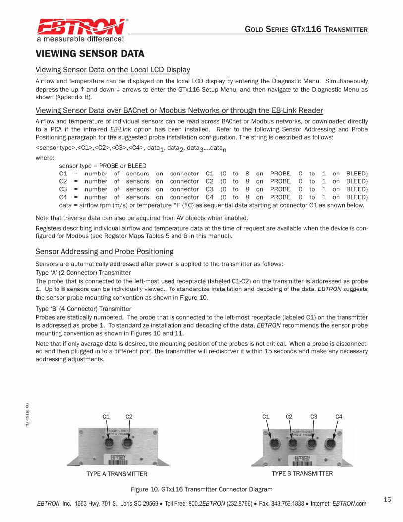
VIEWING SENSOR DATAViewing Sensor Data on the Local LCD DisplayAirflow and temperature can be displayed on the local LCD display by entering the Diagnostic Menu. Simultaneouslydepress the up � and down � arrows to enter the GTx116 Setup Menu, and then navigate to the Diagnostic Menu asshown (Appendix B).
Viewing Sensor Data over BACnet or Modbus Networks or through the EB-Link Reader Airflow and temperature of individual sensors can be read across BACnet or Modbus networks, or downloaded directlyto a PDA if the infra-red EB-Link option has been installed. Refer to the following Sensor Addressing and ProbePositioning paragraph for the suggested probe installation configuration. The string is described as follows:
<sensor type>,<C1>,<C2>,<C3>,<C4>, data1, data2, data3,...datanwhere:
sensor type = PROBE or BLEEDC1 = number of sensors on connector C1 (0 to 8 on PROBE, 0 to 1 on BLEED)C2 = number of sensors on connector C2 (0 to 8 on PROBE, 0 to 1 on BLEED)C3 = number of sensors on connector C3 (0 to 8 on PROBE, 0 to 1 on BLEED)C4 = number of sensors on connector C4 (0 to 8 on PROBE, 0 to 1 on BLEED)data = airflow fpm (m/s) or temperature °F (°C) as sequential data starting at connector C1 as shown below.
Note that traverse data can also be acquired from AV objects when enabled.
Registers describing individual airflow and temperature data at the time of request are available when the device is con-figured for Modbus (see Register Maps Tables 5 and 6 in this manual).
Sensor Addressing and Probe Positioning
Sensors are automatically addressed after power is applied to the transmitter as follows: Type ‘A’ (2 Connector) TransmitterThe probe that is connected to the left-most used receptacle (labeled C1-C2) on the transmitter is addressed as probe1. Up to 8 sensors can be individually viewed. To standardize installation and decoding of the data, EBTRON suggeststhe sensor probe mounting convention as shown in Figure 10.
Type ‘B’ (4 Connector) TransmitterProbes are statically numbered. The probe that is connected to the left-most receptacle (labeled C1) on the transmitteris addressed as probe 1. To standardize installation and decoding of the data, EBTRON recommends the sensor probemounting convention as shown in Figures 10 and 11.
Note that if only average data is desired, the mounting position of the probes is not critical. When a probe is disconnect-ed and then plugged in to a different port, the transmitter will re-discover it within 15 seconds and make any necessaryaddressing adjustments.
Figure 10. GTx116 Transmitter Connector Diagram
TYPE A TRANSMITTER TYPE B TRANSMITTER
C1 C2 C3 C4C1 C2

TM_G
Tx11
6_R
8A
a measurable difference!
®
GOLD SERIES GTX116 TRANSMITTER
EBTRON, Inc. 1663 Hwy. 701 S., Loris SC 29569 • Toll Free: 800.2EBTRON (232.8766) • Fax: 843.756.1838 • Internet: EBTRON.com16
Figure 11. Example of Probe Mounting and Connector Locations for Proper Decoding of Traverse and EB-Link Data
Cabl
Cabling and Transmitter detail is
typical and is
the same for all configurations.C1 C2 C3 C4
GTx116 Transmitter Bottom ViewShowing Connectors
Probe# 1 (To GTx116 C1)
Probe# 2 (To GTx116 C2)
Probe# 3 (To GTx116 C3)
Probe# 4 (To GTx116 C4)
Upstream View
(airflow into page)
TM_G
Tx11
6_R
8A
a measurable difference!
®
GOLD SERIES GTX116 TRANSMITTER
EBTRON, Inc. 1663 Hwy. 701 S., Loris SC 29569 • Toll Free: 800.2EBTRON (232.8766) • Fax: 843.756.1838 • Internet: EBTRON.com 17
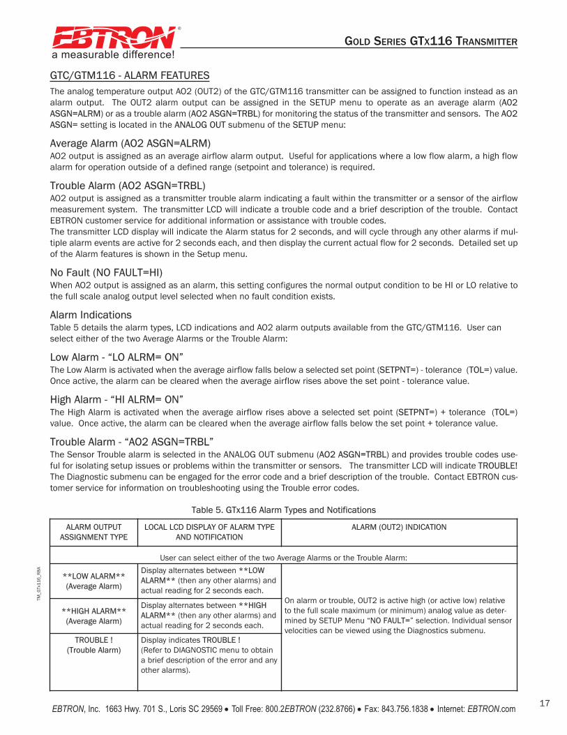
ALARM OUTPUTASSIGNMENT TYPE
LOCAL LCD DISPLAY OF ALARM TYPEAND NOTIFICATION
ALARM (OUT2) INDICATION
User can select either of the two Average Alarms or the Trouble Alarm:
**LOW ALARM**(Average Alarm)
Display alternates between **LOWALARM** (then any other alarms) andactual reading for 2 seconds each.
On alarm or trouble, OUT2 is active high (or active low) relativeto the full scale maximum (or minimum) analog value as deter-mined by SETUP Menu “NO FAULT=” selection. Individual sensorvelocities can be viewed using the Diagnostics submenu.
**HIGH ALARM**(Average Alarm)
Display alternates between **HIGHALARM** (then any other alarms) andactual reading for 2 seconds each.
TROUBLE !(Trouble Alarm)
Display indicates TROUBLE !(Refer to DIAGNOSTIC menu to obtaina brief description of the error and anyother alarms).
Table 5. GTx116 Alarm Types and Notifications
GTC/GTM116 - ALARM FEATURESThe analog temperature output AO2 (OUT2) of the GTC/GTM116 transmitter can be assigned to function instead as analarm output. The OUT2 alarm output can be assigned in the SETUP menu to operate as an average alarm (A02ASGN=ALRM) or as a trouble alarm (AO2 ASGN=TRBL) for monitoring the status of the transmitter and sensors. The AO2ASGN= setting is located in the ANALOG OUT submenu of the SETUP menu:
Average Alarm (AO2 ASGN=ALRM)AO2 output is assigned as an average airflow alarm output. Useful for applications where a low flow alarm, a high flowalarm for operation outside of a defined range (setpoint and tolerance) is required.
Trouble Alarm (AO2 ASGN=TRBL)AO2 output is assigned as a transmitter trouble alarm indicating a fault within the transmitter or a sensor of the airflowmeasurement system. The transmitter LCD will indicate a trouble code and a brief description of the trouble. ContactEBTRON customer service for additional information or assistance with trouble codes. The transmitter LCD display will indicate the Alarm status for 2 seconds, and will cycle through any other alarms if mul-tiple alarm events are active for 2 seconds each, and then display the current actual flow for 2 seconds. Detailed set upof the Alarm features is shown in the Setup menu.
No Fault (NO FAULT=HI)When AO2 output is assigned as an alarm, this setting configures the normal output condition to be HI or LO relative tothe full scale analog output level selected when no fault condition exists.
Alarm IndicationsTable 5 details the alarm types, LCD indications and AO2 alarm outputs available from the GTC/GTM116. User canselect either of the two Average Alarms or the Trouble Alarm:
Low Alarm - “LO ALRM= ON”The Low Alarm is activated when the average airflow falls below a selected set point (SETPNT=) - tolerance (TOL=) value.Once active, the alarm can be cleared when the average airflow rises above the set point - tolerance value.
High Alarm - “HI ALRM= ON”The High Alarm is activated when the average airflow rises above a selected set point (SETPNT=) + tolerance (TOL=)value. Once active, the alarm can be cleared when the average airflow falls below the set point + tolerance value.
Trouble Alarm - “AO2 ASGN=TRBL”The Sensor Trouble alarm is selected in the ANALOG OUT submenu (AO2 ASGN=TRBL) and provides trouble codes use-ful for isolating setup issues or problems within the transmitter or sensors. The transmitter LCD will indicate TROUBLE!The Diagnostic submenu can be engaged for the error code and a brief description of the trouble. Contact EBTRON cus-tomer service for information on troubleshooting using the Trouble error codes.

TM_G
Tx11
6_R
8A1
a measurable difference!
®
GOLD SERIES GTX116 TRANSMITTER
EBTRON, Inc. 1663 Hwy. 701 S., Loris SC 29569 • Toll Free: 800.2EBTRON (232.8766) • Fax: 843.756.1838 • Internet: EBTRON.com18
Table 6. GTC/GTM116 Converting Analog Output Values to Airflow/Temperature
TO CONVERT TO
Airflow (FPM, MPS) Output Voltage/10 x FS1 Output Voltage/5 x FS1 (Output Current-4)/16 x FS1
Airflow (CFM) Area (SQF) x Output/10 x FS1 Area (SQF) x Output/5 x FS1 Area (SQF) x (Output - 4)/16 x FS1
ANALOG OUTPUT SCALING AND TYPE
0-10 VDC 0-5 VDC 4-20 mA
When OUTPUT 1 is Configured as Linear Airflow (FPM, MPS):
Airflow (CFM) Area (SQF) x Output/10 x FS1 Area (SQF) x Output/5 x FS1 Area (SQF) x (Output 4)/16 x FS1
Airflow (LPS) Area (SQM) x Output/10 x FS1 x 1000 Area (SQM) x Output/5 x FS1 x 1000 Area (SQM) x (Output - 4)/16 x FS1 x 1000
TO CONVERT TO0-10 VDC 0-5 VDC 4-20 mA
ANALOG OUTPUT SCALING AND TYPE
When OUTPUT 1 is Configured as Volumetric Airflow (CFM, LPS):
TO CONVERT TO
Airflow (CFM, LPS) Output Voltage/10 x FS1 Output Voltage/5 x FS1 (Output Current - 4)/16 x FS1
TO CONVERT TO
ANALOG OUTPUT SCALING AND TYPE
0-10 VDC 0-5 VDC 4-20 mA
When OUTPUT 2 is Configured as Temperature (°F,°C):
TO CONVERT TOTemp (°F,°C) Output Voltage/10 x (FS2 - MS2) + MS2 Output Voltage/5 x (FS2 - MS2) + MS2 (Output Current - 4)/16 x (FS2 - MS2) + MS2
NOTES:FS1 is AO1 full scale analog output value from ANALOG OUT MENU.FS2 is AO2 full scale analog output value from ANALOG OUT MENU.MS2 is AO2 minimum scale analog output value from ANALOG OUT MENU.
GTC/GTM116 - ANALOG OUTPUT TYPE SELECTION AND SETUP The analog output signal type at OUT1 (airflow) and OUT2 (temperature/alarm) can be set for mA or VDC output by set-ting switches SW1/SW2 (Figure 8) and by selecting the 4-20mA, 0-5 VDC or 0-10VDC ranges in ANALOG OUT sub menuoptions *AO1 RNGE= / *AO2 RNGE= settings (Appendix B). The transmitter is shipped from the factory with SW1/SW2and Setup menu options *AO1 RNGE= and *AO2 RNGE= set for 4-20mA.
GTC/GTM116 - Converting Analog Output Signal Values to Airflow and TemperatureSince the accuracy of the GTC/GTM116 is “percent of reading” there should be no need to reconfigure the default out-put scales listed inside of the transmitter cover. However, factory default settings can be easily reconfigured in the field(see: CHANGING FACTORY DEFAULT SETTINGS).The equivalent volumetric flow full scale reading can easily be determined by multiplying the full scale reading by the freearea where the airflow measuring station is located (free area x 1000 for S.I. scaling when the area is calculated insquare meters). Table 6 lists specific conversion factors for analog voltage or current output options.
GTC116 - OUTPUT TEST - Sending a Test Output Signal to the Host Control SystemA test output signal between 0 and 100% of the full scale output (4-20 mA or 0-5VDC/0-10VDC) can be provided by theGTC/GTM116 transmitter to verify proper conversion of the output signals from the transmitter at the host control sys-tem. To set a fixed output signal for airflow and temperature, navigate to the OUTPUT TEST sub menu in the TOOLS menu(refer to Appendix B in TM_GTx116). OUT1 and OUT2 tests are independently accessed, and the output will maintain the% shown until the “ESC” button is pressed and normal operation resumes. OUTPUT TEST is located in the TOOLS menu.Refer to Appendix B.

TM_G
Tx11
6_R
8A
a measurable difference!
®
GOLD SERIES GTX116 TRANSMITTER
EBTRON, Inc. 1663 Hwy. 701 S., Loris SC 29569 • Toll Free: 800.2EBTRON (232.8766) • Fax: 843.756.1838 • Internet: EBTRON.com 19
GTC116 - TRANSMITTER SETUP FOR RS-485 NETWORK OPERATIONFor RS-485 operation, network connections are made on the GTC116 Combination board as shown in Figure 8, and setup is as follows. Network protocol, MS/TP address, device instance number and baud rate options are all selected with-in the NETWORK section of SETUP menu shown in Appendix B.
NOTE:Prior to power up the GTC116 network configuration and termination switches must be set as shown in Figure 8. Wiring tothe RS-485 network will be accomplished following setting of the GTC116 network configuration switches.
GTC116 - RS-485 Network Options and Communications Menu SettingsThe transmitter is shipped from the factory with the protocol set for BACnet MS/TP Master, address 2, MS/TP Device ID2, Baud rate of 76,800 and no termination. Initial RS-485 communications settings are accomplished within theGTC116 NETWORK sub menu shown in Appendix B. Termination is set up by the TERM DIP switch SW3 located on theCombination card shown in Figure 8.
GTC116 - Setting Transmitter Termination for RS-485 NetworkThe GTC116 is shipped with the Termination switch set for No termination, which is the recommended setting for devicesinstalled on the network bus anywhere EXCEPT at the ends of the bus/segment. EBTRON recommends the followingtermination strategy for devices connected at the ends of the network bus/segment:
The device at one end of the network should be terminated with “End of Line” (or 120 ohm standard) termination,and the device at the other end should be terminated with “Fail Safe Bias” termination. This method will provideproper network termination and will ensure that the bus is in a known state during idle-line conditions (when nodevices are driving the bus). EBTRON GTC116 transmitters include all three termination options for “NoTermination”, “End of Line” (standard 120 ohm) or “Fail-safe Bias” (recommended at one end of the bus).Termination is selected by setting the TERMINATION DIP switch SW3” (Figure 8) on the Combination board.
GTC116 - Setting RS-485 Network ProtocolTransmitter protocol can be set for MS/TP or MODBUS as shown in the NETWORK submenu (Appendix B). Tables 8 and9 list the specific features of each protocol.
GTC116 - Setting Transmitter AddressThe GTC116 is factory set to an address of 2. Each transmitter must be assigned a unique address between 1 and 255(127 BACnet) prior to connecting it to the network by setting the address in the NETWORK submenu (Appendix B).
GTC116 - Setting Baud RateThe GTC116 transmitter default baud rate for MS/TP is 76,800 and for MODBUS is 19,200. Baud rate can be configuredin the NETWORK sub menu (Appendix B).
GTC116 - Setting Device Instance NumberThe GTC116 is factory set with a Device Instance Number of 2. The Device Instance Number can be set as shown in theNETWORK submenu (Appendix B). The Device Instance Number can also be changed to any number between 1 and4,194,302 by writing to the Device Object's Object Identifier Property over the network.
GTC116 - Resetting Communications Options to Factory Default ValuesCommunications options can be reset to factory default values (asterisk) * values using the GTC116 RESET NET menuoption as shown in Appendix B.
Check the network/network segment to ensure that only one device is terminated with either of these methods. If multiple devices are terminated as described above, network segment operation will be adversely affected.

TM_G
Tx11
6_R
8A
a measurable difference!
®
GOLD SERIES GTX116 TRANSMITTER
EBTRON, Inc. 1663 Hwy. 701 S., Loris SC 29569 • Toll Free: 800.2EBTRON (232.8766) • Fax: 843.756.1838 • Internet: EBTRON.com20
GTM116 - TRANSMITTER SETUP FOR ETHERNET NETWORK OPERATION An RJ45 network connector is provided on the GTM116 Ethernet/Analog combination board as shown in Figure 9. Theuser can manually select network protocol (BACnet/IP or BACnet Ethernet - MODBUS TCP is always enabled), IP addressand device instance number, or can set the GTM116 to automatically configure itself when used on a network/segmentwith a DHCP server. By default, the DHCP setting is OFF (*DHCP=OFF) for manual device configuration, with BACnet IPprotocol (BAC MODE=IP), a static IP address of 10.0.0.100, a subnet mask of 255.255.255.0, and with gateway set for10.0.0.10. These values can be changed within the NETWORK sub menu (Appendix B) as described below.
When IP configuration is complete, confirm IP communications locally by “pinging" the assigned GTM116 IP address andobserving 5 rapid blinks of the ACTIVITY LED (Figure 9). For example, “ping 10.0.0.100” for the GTM116 factory defaultIP address of 10.0.0.100. and observe 5 blinks of the GTM116 ACTIVITY LED for each ping received.
GTM116 - Selecting Static or Dynamic IP SettingsFor automated device configuration on a network/segment with a properly operating DHCP server, set *DHCP=ON asshown in Appendix B. Then, set *BAC MODE= for BACnet/IP (factory default) or BACnet Ethernet operation, and set *DI=device instance number (factory default=2) as described below. No additional device configuration is required.
For manual device configuration of the GTM116, set menu item *DHCP=OFF (factory default) as shown in Appendix B.When manually changing IP settings (*DHCP=OFF), the display will blink the 3-digit address segment that is underchange. Change the blinking segment by pressing the UP or DOWN buttons to arrive at the desired segment setting.Depress the ENTER key to set this segment and to move the blinking cursor to the next (right) segment. Set this seg-ment as before, using the UP or DOWN arrow buttons, and then depress ENTER to store and move to the next (right) seg-ment. Repeat this until the last segment has been selected, and then depress ENTER to store the new address setting.
GTM116 - Setting Ethernet Transmitter IP AddressThe GTM116 is factory set with an IP address of 10.0.0.100. Each transmitter must be assigned a unique address onthe network/segment it is connected to. To change the IP address, navigate to the *IP=10.0.0 menu item as shown inAppendix B and set segments as previously described. (See note above regarding *DHCP=OFF).
GTM116 - Setting Subnet MaskTo change this value, navigate to the *MASK=255.2... menu item as shown in Appendix B, and set new segment valuesas previously described. (See note above regarding *DHCP=OFF).
GTM116 - Setting Gateway IPTo change this value, navigate to the *GATE=10.0.0... menu item as shown in Appendix B, and set new segment valuesas previously described. (See note above regarding *DHCP=OFF).

TM_G
Tx11
6_R
8A
a measurable difference!
®
GOLD SERIES GTX116 TRANSMITTER
EBTRON, Inc. 1663 Hwy. 701 S., Loris SC 29569 • Toll Free: 800.2EBTRON (232.8766) • Fax: 843.756.1838 • Internet: EBTRON.com 21
GTM116 - Setting BACnet Protocol ModeThe GTM116 is factory set with *BAC MODE=IP for BACnet IP protocol operation. This menu item can be changed to*BAC MODE=ETH for BACnet Ethernet protocol as shown in Appendix B. Tables 7, 8 and 9 provide details of TCP/IP,BACnet Objects and Modbus Register Maps respectively. Note that Modbus IP is always enabled regardless of *BACMODE setting.
NOTE:For BACnet IP operation, use port 47808. For Modbus TCP operation, use port 502. Modbus IP is always enabled regard-less of the *BAC MODE setting.
GTM116 - Setting Device Instance NumberThe GTM116 is factory set with a Device Instance Number of 2 (*DI=2). The Device Instance Number can be set to anyvalue between 0 and 4194302 as shown in Appendix B. The Device Instance Number can also be changed by writing tothe Device Object's Object Identifier Property over the network.
GTM116 - Resetting Communications Options to Factory Default ValuesCommunications options can be reset to factory default values (asterisk) * values using the GTM116 RESET NET menuoption as shown in Appendix B.
GTM116 - ETHERNET WIRING CONNECTIONSEnsure that the transmitter network settings have been properly set up as previously described. Ensure that the powerswitch is in the “OFF” position. Connect the 10/100 base-T ethernet connection (RJ45) to the female connector on theoutput card as shown in Figure 9.
Tables 8 and 9 list the specific values provided for BACnet and Modbus communication protocols.
TCP/IPhttp://10.0.0.100
(or your custom IP address)
Table 7. GTM116 TCP/IP Example
GTM Data

TM_G
Tx11
6_R
8A
a measurable difference!
®
GOLD SERIES GTX116 TRANSMITTER
EBTRON, Inc. 1663 Hwy. 701 S., Loris SC 29569 • Toll Free: 800.2EBTRON (232.8766) • Fax: 843.756.1838 • Internet: EBTRON.com22
Table 9. GTx116 Modbus Register Map
Table 8. GTx116 BACnet Object List
BACnet MS/TP
Modbus
Analog Inputs
Type, IDDefault Units
Device, 2 x = C for RS-485 x = M for Ethernet
AI, 1 CFM
AI, 2 °F
AI, 3
Notes:
GTx 116
Average Flow
Avgerage Temperature
Alarm Status
Name
Type, IDDefault Units
xx
Analog ValuesAV, 1 Area sq.ft.
AV, 2 Traverse Data Status 0=None, 1=Flow, 2=Temp, 3=Both
AV, 3 Flow Traverse FPM
AV, 18 Flow Traverse FPM
AV, 19 Temperature Traverse °F
AV, 34 Temperature Traverse °F
NNotes: 1. Flow and Temp traverse must be enabled through AV2.2. User Executed Services Supported: Subscribe COV, Read Property, Write Property, Device Communication Control, Who-Is.
x
Name
Function Address Type Units Description Range/Value
2 10001 boolean Trouble Status 0:OK, 1:Trbl4 30001-30002 float FPM Average Airflow 0 to 15,0004 30003-30004 float °F Average Temperature -20 to 1604 30005 word Number of Inserts 0 to 84 30006 word 0
4 30007 word Alarm Status
0: No alarm1: High Alarm2: Low Alarm3: Both
4 30008 word Connector C1 Sensors 0 to 84 30009 word Connector C2 Sensors 0 to 84 30010 word Connector C3 Sensors 0 to 84 30011 word Connector C4 Sensors 0 to 8
30012-30043 Airflow Flow Traverse30012-30013 Insert 1 Flow
30042-30043 Insert 16 Flow
4 float 0 to 15,000FPM
30044-30075 Temperature Traverse30044-30045 Insert 1 Temp
30074-30075 Insert 16 Temp
4 30076 30077 float Sq Ft Area
4 -20 to 160float °F
4 30076-30077 float Sq.Ft. Area 0 to 100
4 300202 word Float word order0: high word first;1: low word first
NOTE: For GTM116 BACnet IP operation, use port 47808.
NOTE: For GTM116 Modbusoperation, use port 502.Modbus IP is always enabledregardless of *BAC MODEsetting.
Modbus RTUfor GTC116
Modbus TCPfor GTM116

TM_G
Tx11
6_R
8A
a measurable difference!
®
GOLD SERIES GTX116 TRANSMITTER
EBTRON, Inc. 1663 Hwy. 701 S., Loris SC 29569 • Toll Free: 800.2EBTRON (232.8766) • Fax: 843.756.1838 • Internet: EBTRON.com 23
GTL116 - LONWORKS TRANSMITTER SETUPThe GTL116 includes a full featured LonWorks compatible interface. The EBTRON LonWorks output card (part number800-5030) plugs directly onto the GTL116 main circuit board as shown in Figure 12. It includes a high speed FTT-10A,78k baud Free Topology transceiver interface that is relatively insensitive to network wiring topology. The GTL116 maybe pre-configured using the GTL116.XIF file available for download at www.ebtron.com/lonworks, or configured at instal-lation via direct LonWorks parameter upload from the GTL116 transmitter. A service push-button and LED are providedfor standard installation. A “Wink” LED is provided for easy device identification. An “Activity” LED and separate trans-mit and receive “TX” and “RX” provide visual indication of transmitter and communication status. The “Activity” LED nor-mally flashes on for 1 second, off for 1 second when the card is commissioned and online, and remains illuminated con-stantly if there is an error
To wire the output signal, slide the cover plate up and off of the enclosure. Ensure that the power switch is in the “OFF”position. Connect network cables to the small, three position output terminal labeled “OUTPUT” on the upper left handside of the main circuit board (shown below) at terminals 1 and 2 only.
GTL116 - LONWORKS NETWORK CONNECTIONSConnect the transmitter output to the LonWorks bus in a "daisy-chain" configuration using a shielded, twisted pair com-munication wire with a signal ground conductor (3 wires and a shield). The transmitter provides an output that is isolat-ed from the main power input. Connect the LonWorks cable at the “OUTPUT” terminal block as follows:
OUTPUT TERMINAL SIGNAL DESCRIPTION
1 NET+2 NET-
COM COMMON (NOT USED)
(The shield will typically be grounded at one end of the bus and not connected to the transmitter terminals.)
TM_G
Tx11
6_R
8A
Figure 12. GTL116 LonWorks Transmitter Interior Detail
CAUTION HOT
GTx116 Main
ON
OFF
ESC ENTERPGM
CONTRAST
24VAC INL2 L1
OUTPUTCOM
POWER
REPLACE WITH
1.5 AMP
FAST ACTING ONLY
EBTRON INC.400-1810 REV. J
U11U10U9
J6
U4
D4
U1
C1
VR1
J4L1
Z1
D2
D1
C5
HS2HS1
VR2
C6
C4C3
C2
R5R4
R3
LCD1
R2
J1
F1 J2
J3
SW1
R1
EG1
R26R25
R24R23R22R21
R20
R19R18
R17R16R15
R14
R13
R12
R10
R11
U8U7
U3
U6
U24U23U22U21
U20U19U18U17
U16U15U14U13
U12
R6
R59R58R57
R56R55R54R53R52R51R50R49
R48R47R46R45R44R43R42R41
R40R39R38R37R36R35R34R33
R32R31R30R29R28R27
U5
U2
C9C8
C12C11
C7
C22C21
C20
C19
C18
C17
C16C15C13
C10
C14
R9R8
R72R71R70
R7
R69R68R67R66R65
R64R63R62R61R60
+
+
MH1
D3
C23
J7
J8
XTAL1
TP1
TP9TP8TP7TP6TP5TP4TP3TP2 TP17TP16TP14TP13TP12TP11TP10 TP15
SW5SW4SW2 SW3
D1
D4D3
C4
C3
C6
U2
MH1
U1
U3
R1
C5
C2
MH3
C1
EBTRON, INC.400-1850 REV. E
GTL116 LOut
SERVICE
WINK
YEL
GRN
MH2
C15
C16
U6
C8
R7 R8
D6SW1
R4
R10R9
R6
D7
D5
C7
J1
XFMR1
SG1 SG2
D21
10
1
+
+1
U4
C11C10
C9
C14
C12
C13
XTAL1U5
J2
R3R2
R5
1
64
33
32
1
1
10
1 - (connect to network)
2 - (connect to network)
COM - Not used
LonWorks Output CardP.N. 800-5030
LCD Display
Power Switch
TX LED Green
RX LED Green
Service LED Yellow
Service Button
Wink LED Green
Transmitter Status LED.(Green 1 second flash normal;
2 second flash for fault)
Activity LED Red

TM_G
Tx11
6_R
8A
a measurable difference!
®
GOLD SERIES GTX116 TRANSMITTER
EBTRON, Inc. 1663 Hwy. 701 S., Loris SC 29569 • Toll Free: 800.2EBTRON (232.8766) • Fax: 843.756.1838 • Internet: EBTRON.com24
GTL116 - LONWORKS INTERFACE
IntroductionThe Ebtron LonWorks interface adapter is designed to provide an output capability for connection to an EchelonLonWorks based network. Two basic function blocks are provided. These include a node object and a gtx116 functionblock.
The node object is used for overhead activities on the LonWorks bus. This object is of little interest to the end user.
The gtx116 function block contains a set of network variables and configuration properties that allow the end user tomonitor various parameters related to airflow, pressure, and temperature that are generated by the transmitter.
Basic DescriptionThe LonWorks protocol is based on "network variable objects"("nvo"). Each device on the network communicates withother devices by "connecting" to the variables of the device it wishes to monitor. These variables consist primarily of pre-defined types that are part of the network specification.
Additionally, a special class of network properties is defined to allow the configuration of various parameters within adevice. These are intended to control the basic operation of a device.
All network variables are defined in terms of "SNVT_xxx". SNVT is an acronym for Standard Network Variable Type. "xxx"is a descriptive phrase that relates to the units used by the parameter represented by the variable. All of the variablesdescribed below are always visible on the network; however, some variables are meaningful only with certain types ofsensors attached to the transmitter. Tables 10 through 17 describe each of the variables used and the configurationproperties for each.
All configuration properties are defined in terms of "SCPTxxx". SCPT is an acronym for Standard Configuration PropertyType. There are configuration properties that apply to multiple objects, but may not be listed directly under them whenviewed on the network. Check the "applies to" tag in the description for the configuration property in the following sec-tions.

TM_G
Tx11
6_R
8A
a measurable difference!
®
GOLD SERIES GTX116 TRANSMITTER
EBTRON, Inc. 1663 Hwy. 701 S., Loris SC 29569 • Toll Free: 800.2EBTRON (232.8766) • Fax: 843.756.1838 • Internet: EBTRON.com 25
GTL116 - VELOCITY AND FLOW VARIABLES CONFIGURATIONThis section details the air flow and air velocity variables and how the configuration properties relate to them.
Velocity and Flow Variables
nvoAirVel (SNVT_speed_mil - Air Velocity)This variable provides simple linear airflow in feet/second.
nvoAirFlow (SNVT_flow - Airflow)This variable provides volumetric airflow in cubic feet/min. For this variable to be meaningful, the ductArea configura-tion property must be set.
nvoAirFlowFl (SNVT_flow_f - Airflow Float)This variable provides volumetric airflow in cubic feet/min. For this variable to be meaningful the ductArea configurationproperty must be set.
Velocity and Flow Configuration Properties
nvoAirVel (SCPTmaxSendTime - Maximum Time Between Updates)This configuration property sets the maximum time to elapse between updates to the network for velocity and flow to occur.
nvoAirVel (SCPTminSendTime - Minimum Time Before Updates)This configuration property sets the minimum time to elapse before an update to the network for velocity and flow maybe sent. This configuration property takes priority over maxSendTime and sndDelta.
nvoAirVel (SCPTsndDelta - Minimum Change for Update)This configuration property sets the minimum change in velocity that will cause an update of flow and velocity to the net-work. The change is only checked for in velocity, and when the minimum is reached updates will occur for nvoVel,nvoFlow, and nvoFlowFl.
nvoAirFlow (SCPTductArea - Duct Area for Air Flow Calculation)This configuration property sets the duct area to be used in flow calculations. Note that this variable must be set to anon-zero value to get flow information.
Variable Name Variable Type Measurement Type Category TypeResolution Units
Air Flow Sensor Objects
ResolutionnvoAirVel SNVT_speed_mil Linear Velocity Unsigned Long 0.001 Feet/secondnvoAirFlow SNVT_flow Flow Volume Unsigned Long 1 Cubic feet/minnvoAirFlowFl SNVT_flow_f Flow Volume Floating Point n/a Cubic feet/min
nvoAirVel SCPTmaxSendTime Time Signed Long 0.1 SecondsnvoAirVel SCPTminSendTime Time Signed Long 0.1 Seconds
Air Flow Sensor Configuration Properties
nvoAirVel SCPTminSendTime Time Signed Long 0.1 SecondsnvoAirVel SCPTminDelta Linear Velocity Unsigned Long 0.001 Feet/secondnvoAirFlow SCPTductArea Area Unsigned Long 0.0002 Square Meters
For the “nvoAirFlow” and “nvoAirFlowFl” variables to be meaningful, the ductArea configuration property must be set.
Table 11. GTL116 LonWorks Node Velocity and Flow Configuration Properties
Table 10. GTL116 LonWorks Node Velocity and Flow Variables

TM_G
Tx11
6_R
8A
a measurable difference!
®
GOLD SERIES GTX116 TRANSMITTER
EBTRON, Inc. 1663 Hwy. 701 S., Loris SC 29569 • Toll Free: 800.2EBTRON (232.8766) • Fax: 843.756.1838 • Internet: EBTRON.com26
GTL116 - AREA INPUT VARIABLEThis section details the network input variable area.
Area Input Variable
nviArea (SNVT_area – Duct Area for Air Flow Calculation)This network input sets the duct area to be used in flow calculations. This variable is essentially a copy ofnvoAirFlow:SCPTductArea; only one of these inputs needs to be configured before using nvoAirFlow or nvoAirFlowFl.
GTL116 - PRESSURE VARIABLES AND CONFIGURATIONThis section details the pressure variables and how the configuration properties relate to them.
Pressure Variables
nvoPrecisePres (SNVT_press_p - Airflow Pressure)This variable provides air pressure in inches of H2O. For this variable to be meaningful a bleed sensor must be attachedto the transmitter.
nvoFloatPres (SNVT_press_f - Airflow Pressure Float)This variable provides air pressure in inches of H2O. For this variable to be meaningful a bleed sensor must be attachedto the transmitter.
Pressure Configuration Properties
nvoPrecisePres (SCPTmaxSendTime - Maximum Time Between Updates)This configuration property sets the maximum time to elapse between updates to the network for pressure to occur.
nvoPrecisePres (SCPTminSendTime - Minimum Time Before Updates)This configuration property sets the minimum time to elapse before an update to the network for pressure may be sent.This configuration property takes priority over maxSendTime and sndDelta.
nvoPrecisePres (SCPTsndDelta - Minimum Change for Update)This configuration property sets the minimum change in pressure that will cause an update for pressure to the network.When this change is met both nvoPrecisePres and nvoFloatPres will be updated on the network.
Variable Name SNVT Measurement Type Category TypeResolution Units
nvoPrecisePres SNVT_press_p Pressure Signed Long 0.00001 Inches of H2OnvoFloatPres SNVT_press_f Pressure Floating Point n/a Inches of H2O
Dynamic Pressure Sensor Object
nvoPrecisePres SCPTmaxSendTime Time Signed Long 0.1 SecondsnvoPrecisePres SCPTminSendTime Time Signed Long 0.1 SecondsnvoPrecisePres SCPTsndDelta Pressure Signed Long 0.0001 Inches of H2O
Dynamic Pressure Sensor Configuration PropertiesTable 14. GTL116 LonWorks Node Pressure Configuration
Table 13. GTL116 LonWorks Node Pressure Variables
Variable Name Variable Type Measurement Type Category TypeResolution Units
nviArea SNVT_area Area Unsigned Long 0.0002 Square Meters
Area Object
Table 12. GTL116 LonWorks Area Input Variable

TM_G
Tx11
6_R
8A
a measurable difference!
®
GOLD SERIES GTX116 TRANSMITTER
EBTRON, Inc. 1663 Hwy. 701 S., Loris SC 29569 • Toll Free: 800.2EBTRON (232.8766) • Fax: 843.756.1838 • Internet: EBTRON.com 27
Temperature Variables and Configuration PropertiesThis section details the temperature variable and how the configuration properties that relate to it.
nvoTemp (SNVT_temp_p - Temperature Variable)This network variable provides temperature in degrees Fahrenheit.
Temperature Configuration Properties
nvoTemp (SCPTmaxSendTime - Maximum Time Between Updates)This configuration property sets the maximum time to elapse between updates to the network for temperature to occur.
nvoTemp (SCPTminDeltaTemp - Minimum Change for Update)This configuration property sets the minimum change in temperature that will cause an update of nvoTemp to the net-work.
nvoTemp (SCPTminSendTime - Minimum Time Before Updates)This configuration property sets the minimum time to elapse before an update to the network for temperature may besent. This configuration property takes priority over maxSendTime and minDeltaTemp.
GTL116 - DEFAULT DELTA VALUESThis section details the default Delta values which determine when updates are sent from the transmitter to the network.The Delta Values in Table 17 are set with a large factory default value to prevent any undesired messages from beingsent to the network. Refer to the preceding paragraphs for a description and configuration of the Delta values.
nvoTemp SCPTmaxSendTime Time Signed Long 0.1 SecondsnvoTemp SCPTminDeltaTemp Temperature Signed Long 0.001 Degrees FnvoTemp SCPTminSendTime Time Signed Long 0.01 Seconds
Temperature Sensor Configuration Properties
Delta ValuesnvoAirVel SCPTsndDelta 200 fpsnvoPrecisePres SCPTsndDelta 1 iWcnvoTemp SCPTminDeltaTemp 160 °F
Table 17. GTL116 LonWorks Node Temperature Variable
Table 16. GTL116 LonWorks Node Temperature Variable
V i bl N SNVT M t T C t Type U itVariable Name SNVT Measurement Type Category TypeResolution Units
nvoTemp SNVT_temp_p Temperature Signed Long 0.01 Degrees F
Table 15. GTL116 LonWorks Node Temperature Variable

TM_G
Tx11
6_R
8A
a measurable difference!
®
GOLD SERIES GTX116 TRANSMITTER
EBTRON, Inc. 1663 Hwy. 701 S., Loris SC 29569 • Toll Free: 800.2EBTRON (232.8766) • Fax: 843.756.1838 • Internet: EBTRON.com28
EB-Link WIRELESS INFRARED COMMUNICATIONS OPTIONThe EB-Link wireless infrared communications option is ideal for air balance contractors, engineers, building ownersand/or contractors who desire fast and accurate measurement without additional interfacing. Individual and averagesensor airflow(s) and temperature(s) from GTx116 transmitters equipped with the EB-Link option can be instantly trans-ferred to the new EB-Link Reader model EBR-1000 or to a Palm® or Microsoft® Windows Mobile® operating system PDA.This method reduces the data acquisition time and sampling error inherent with hand held measurements. The data canthen be transferred to your PC for review, update or analysis.
In addition, a Setup-Upload feature (available only with the PDA software version) permits rapid transfer of preset trans-mitter setup configuration to another EB-Link equipped GTx116 transmitter. This is especially useful when multiple trans-mitters are to be set up or modified.
Real-time duct flow/temperature traverses can be accomplished quickly and easily using the GTx116 transmitterequipped with the EB-Link option. Individual airflow and temperature data can be returned directly to your EB-LinkReader or PDA (using Palm® or Microsoft® Windows Mobile® operating system). The data can also be returned overBACnet or Modbus when probes are connected to a type GTC116/GTM116 networked transmitter.
This innovative feature is ideal for balancers and commissioning agents that desire “on-the-fly” airflow and temperaturetraverses. The advantages of using permanently installed GP1 probes include nearly instantaneous traverse data (nosampling error over time), accurate and repeatable measurement and simple report generation using the Microsoft®
Excel® spreadsheet provided by EBTRON. Performing duct traverses with permanently mounted EBTRON airflow probeseliminates the requirement to make additional sampling holes in the duct, and reduces the need to carry around the jobsite cumbersome equipment and ladders to accomplish them.
EB-Link Card Installation
The EB-Link card must be installed on the GTx116 main board in order to access sensor data with your PDA. If the EB-Link card is ordered separately from the transmitter, it should be installed after the transmitter is mounted.
To install the EB-Link option card, slide the cover up and off of the transmitter enclosure. Turn the power switch, SW1,to the “OFF” position on the transmitter main circuit board. Observe ESD precautions when handling and installing theEB-Link card. Touch a grounded object, such as a metal duct, before removing the EB-Link card from the anti-static pack-age. Remove the EB-Link card from the anti-static package, being careful not to touch exposed components or circuitboard traces (hold the card by the edges as indicated on left frame of Figure 13). With the components facing in towardsthe center of the main circuit board, carefully plug the EB-Link card into the header connector labeled J5 on the righthand side of the transmitter just below the LCD display (center frame, Figure 13). Do not press on any components. Thecard should stand on its own when properly installed (right frame of Figure 13).
Figure 13. EB-Link Installation Detail
CAUTION: Observe all electrostatic Discharge (ESD) handling precautions. Do not touch internal components.Failure to observe ESD precautions can cause damage to components.
CAUTION: Turn the transmitter “POWER” switch to the “OFF” position before installing the EB-Link card. Failureto do so can cause damage to the EB-Link card and/or the transmitter.

TM_G
Tx11
6_R
8A
a measurable difference!
®
GOLD SERIES GTX116 TRANSMITTER
EBTRON, Inc. 1663 Hwy. 701 S., Loris SC 29569 • Toll Free: 800.2EBTRON (232.8766) • Fax: 843.756.1838 • Internet: EBTRON.com 29
Obtaining and Installing EB-Link SoftwareEB-Link software can be downloaded free of charge at www.ebtron.com/eblink.Versions are available for the EB-Link Reader, or for PDAs (for either the Palm® orMicrosoft® Windows Mobile® operating systems) as shown in Figure 14. Figure 15shows the EB-Link in use.
The software includes all of the files required for operation of the EB-Link Reader or forPDAs as well as a Microsoft® Excel® spreadsheet for converting the PDA files to a Testand Balance report.
EB-Link Reader SoftwareThe EB-Link Reader software is designed for operation on Windows XP (or later) oper-ating systems and permits file management and time synchronization for the EB-LinkReader.
The latest version of the EB-Link Reader software, as well as installation, operationand descriptions of all EB-Link Reader functions are contained in the EB-Link ReaderTechnical Documentation available at www.ebtron.com/eblink.
EB-Link Software for PDA DevicesThe EB-Link Software for PDA Devices is designed for operation with PDA devices usingthe Palm® or Microsoft® Windows Mobile® operating systems. The software includes aMicrosoft® Excel® spreadsheet that allows for the pre-configuration, review or modifica-tion of GTx116 transmitter setup parameters.
The latest version of the software, as well as installation, operation and descriptions ofall EB-Link functions are contained in the readme.txt file that is provided with thedownload.
Real-time duct traverses can be accomplished quickly and easily using the GTx116transmitter equipped with the EB-Link option. Individual airflow and temperature datacan be returned directly to your PDA (Palm® or Microsoft® Windows Mobile® operatingsystem). Data can also be returned over BACnet or Modbus when probes are connect-ed to a GTC116, RS-485 transmitter.
Real Time Duct Traverses Using EB-LinkSimply slide the GTx116 cover up and off of the GTx116 transmitter enclosure andpoint your EB-Link Reader or PDA to the EB-Link sensor located just to the right andbelow the transmitter LCD display as shown in Figure 15 (note: the EB-Link card optionmust be installed). The acquisition of data takes less than 10 seconds to complete.After acquiring data, you can display individual or average airflow and/or temperaturedata on your EB-Link Reader or PDA. Saved data (stored as a comma separated valueCSV file) can also be downloaded to your PC for creation of individual test and balancereports using the software of your choice, or with the Microsoft® Excel® spreadsheetthat EBTRON has included with the PDA software. Note that the traverse sensor datais averaged to provide more stable readings.
Note also that on rectangular ducts, the EBTRON Excel® balance report will alwaysshow the traverse data starting at the top left position of the duct when viewing fromupstream of the flow station, regardless of the orientation of the probes, when theprobes are installed as indicated in the configuration diagrams of Figure 11. Onround/oval ducts, the balance report will always show traverse data in columns, start-ing with probe number one.
If traverse data is desired, ensure that probes are installed using the mounting convention specified in Figure 11. Proper instal-lation simplifies sensor location decoding during data analysis.
NOTE
Figure 15. Typical EB-LinkData Acquisition
Figure 14. EB-Link Readerand PDA Devices
EB-Link PDACommunication Detail
EB-Link ReaderCommunication Detail
EB-Link and PDA
EB-Link Reader

TM_G
Tx11
6_R
8A
a measurable difference!
®
GOLD SERIES GTX116 TRANSMITTER
EBTRON, Inc. 1663 Hwy. 701 S., Loris SC 29569 • Toll Free: 800.2EBTRON (232.8766) • Fax: 843.756.1838 • Internet: EBTRON.com30
FIELD ADJUSTMENTSALTITUDE CORRECTION ADJUSTMENTThe Altitude Correction Adjustment allows for correction of airflow readings at the installed site altitude and more pre-cise readings regardless on installed altitude. Refer to the SETUP MENU of Appendix B for the *ALT= menu item, andset this value to the installation altitude.
ADJUSTING THE LOW LIMIT CUTOFFThe low limit cutoff forces the output signal for the airflow rate to zero whenever the airflow rate calculated falls belowthe specified Low Limit value. This feature is useful on outside air intakes that often indicate false airflow rates, inducedby transient wind gusts or when the intake damper is closed and there is no net flow across the damper. Readings of100 FPM or more are not uncommon on many outside air intake applications when the intake damper is closed and area result of air movement in the intake plenum (not a malfunction in the airflow measuring device). Setting the low limitto a value significantly below the control setpoint and higher than the threshold flow for false wind readings simplifiescontrol and interpretation of the airflow rate signal on many applications.
To set the low limit cutoff, enter the Setup menu and set “*LLIMIT={desired value in FPM (MPS in SI units)}” as shownin Appendix B.
FACTORY CALIBRATION ADJUSTMENTSThe factory calibration should not require adjustment if the sensor probes are installed in accordance with publishedinstallation guidelines. However, some installations may not meet placement guidelines or commissioning requirementsmay dictate field adjustment. Field adjustment may improve the “installed accuracy” of GTx116 systems when determin-ing volumetric flow rates. Only the Output 1 signal, airflow rate, can be adjusted. Ensure that the reference device andtechnique used to determine the airflow rate in the field are suitable for such measurement. Select a location that isacceptable for the device being used as the reference, recognizing that this may not be the same location where theEBTRON airflow station is installed. The inherent accuracy of field measurement will not be better than ±5% of readingand can often exceed ±10%. Do not adjust the output of the GTx116 if the difference between the transmitter and thefield measurement is less than 10%.
Field Adjustment Wizard - AUTOMATED FIELD ADJUSTMENT
Overview of the Field Adjustment WizardThe simple to use Field Adjustment Wizard provides a one or two point automated menu driven field adjustment to fac-tory calibration of the OUTPUT 1 airflow rate signal.
Engaging and Using the Field Adjustment WizardUse Appendix B to navigate to the FIELD ADJUST submenu. Appendix B provides details of the FIELD ADJUST menu andhow to use it in applications for one or two point automated field adjustment. If you wish to disable the FIELD ADJUSTsetting, navigate to the ADJUSTMENTS submenu and set FLOW ADJ=OFF.
MANUAL ADJUSTMENT OF FACTORY OFFSET/GAIN CALIBRATIONIf you prefer, you can instead perform a manual adjustment at one or two points. The GTx116 firmware can be adjustedfor Output 1 signal “gain” and “offset”. To adjust the output signal “gain”, the “FLOW ADJ” override must be set to“*FLOW ADJ=ON” from the Setup Menu. The adjustments affect both the LCD display and output signal. When “*FLOWADJ=OFF” is set, adjusting the output signal “offset” and/or “gain” does not affect the transmitter output.
Fluctuations in the airflow output signal are normal. EBTRON’s laboratory research indicates that dampening true fluctuationswill result in poor control and a larger dead-band of operation.

TM_G
Tx11
6_R
8A
a measurable difference!
®
GOLD SERIES GTX116 TRANSMITTER
EBTRON, Inc. 1663 Hwy. 701 S., Loris SC 29569 • Toll Free: 800.2EBTRON (232.8766) • Fax: 843.756.1838 • Internet: EBTRON.com 31
Procedure for 1 Point Field AdjustmentSelect an airflow rate that represents a valid operating condition for the system. Set fan speed, dampers and VAV boxesto a fixed speed or position when measurements are taken. Complete the following worksheet to determine the gain set-ting to be set on the transmitter.
Direct Entry of Gain factor Method(most accurate):1. Enter the setup menu and set “*FLOW ADJ=OFF”. This is the factory default setting and disables any adjust-ments, returning the unit to its original factory calibration.2. __________ Record the transmitter output by taking the visual reading from the transmitter LCD. Readingscan be taken by the host controls if the output signal conversion has been confirmed. Time averaging the data willimprove field recalibration.3. __________ Record the reference reading. Make sure that the unit of measure (FPM, CFM) is identical forboth the transmitter and the reference. If the unit of measure is velocity (FPM), make sure that the reference air-flow measurement was corrected for the area where the measurement was taken.4. __________ Calculate the gain factor (m): m=line 3/line 2.5. Enter the setup menu and set “*FLOW ADJ=ON”. 6. Set “*GAIN={value calculated in line 4}”.7. Confirm that “*OFF=0.00”. 8. Press the “ESC” button until you return to the normal operating mode. Field adjustment is complete.
Procedure for 2 Point Field AdjustmentSelect the minimum and maximum airflow rate that the airflow station will encounter as a valid operatingcondition for the system. Set fan speed, dampers and VAV boxes to a fixed speed or position when meas-urements are taken. Complete the following worksheet to determine the gain and offset settings to be seton the transmitter.
1. Enter the setup menu and set “*FLOW ADJ=OFF”. This is the factory default setting and disables anyadjustments, returning the unit to its original factory calibration. MEASUREMENTS MUST BE RECORD-ED IN FPM.
2. Set the minimum airflow rate.
3. __________ Record the transmitter airflow rate by taking the visual reading from the transmitter LCD.Readings can be taken by the host controls if the output signal conversion has been con-firmed. Time averaging the data will improve field recalibration.
4. __________ Record the reference airflow rate. Make sure that the unit of measure has been convert-ed to FPM. Make sure that the reference airflow measurement was corrected for the areawhere the measurement was taken.
5. Set the maximum airflow rate.
6. __________ Record the transmitter airflow rate.
7. __________ Record the reference airflow rate.
8. __________ Calculate the gain factor (m): m=(line 7 - line 4)/(line 6 - line 3).
9. __________ Calculate the offset factor (b): b=(line 4 - (line 8 x line 3).
If more than 2 points are available, perform a linear regression on the data to determine gain and offset.
10. Enter the setup menu and set “*FLOW ADJ=ON”.11. Set “*GAIN={value calculated in line 8}”.11. Set “*OFF={value calculated in line 9}”.12. Press the “ESC” button until you return to the normal operating mode. Field adjustment is complete.

TM_G
Tx11
6_R
8A
a measurable difference!
®
GOLD SERIES GTX116 TRANSMITTER
EBTRON, Inc. 1663 Hwy. 701 S., Loris SC 29569 • Toll Free: 800.2EBTRON (232.8766) • Fax: 843.756.1838 • Internet: EBTRON.com32
MAINTENANCEWhen transmitter and probes are installed in accordance with EBTRON guidelines, instrument difficulties are rare. Issuesmay easily be resolved by viewing Diagnostic data from the Diagnostic Menu (Appendix B) and by proceeding through thefollowing troubleshooting guides (Tables 18 through 22). Customer support is available Monday - Friday from 8 AM to4:30 PM ET, at 800-2EBTRON (232.8766). EBTRON Diagnostic Customer Service forms are available on-line atwww.ebtron.com to assist us in accurately diagnosing issues and will greatly expedite their resolution. A sketch of theinstallation, along with the control sequence of operations is recommended to help us diagnose problems. Fax the infor-mation to 843.756.1838 before you call, and have it available when speaking with the Customer Service team. Addressall correspondence to the EBTRON Customer Service Department. Additional information is also available from your localEBTRON representative.
STANDARD LIMITED PARTS WARRANTYIf any EBTRON product fails within 36 months from shipment, EBTRON will repair/replace the device free of charge asdescribed in the company’s warranty contained in EBTRON’s TERMS AND CONDITIONS OF SALE. Defective equipmentshall be shipped back to EBTRON, freight pre-paid, for analysis.

TM_G
Tx11
6_R
8A
a measurable difference!
®
GOLD SERIES GTX116 TRANSMITTER
EBTRON, Inc. 1663 Hwy. 701 S., Loris SC 29569 • Toll Free: 800.2EBTRON (232.8766) • Fax: 843.756.1838 • Internet: EBTRON.com 33
Problem Possible Cause RemedyNo LCD display indication and the green TransmitterStatus LED (D3) on the main circuit board is not illumi-nated.
Power switch not in the "ON" position. Move the power switch to the "ON" position.
Improper supply voltage to the power input terminalblock.
Ensure that 24VAC power is connected to L1 and L2 ofthe POWER terminal block and that the voltage with thepower switch in the "ON" position is between 22.8 and26.4 VAC.
Blown fuse. Check power wiring. Ensure that multiple devices wiredon a single transformer are wired "in-phase". Replacefuse only with a 1.5 amp, fast-acting fuse after the prob-lem has been identified and corrected.
No LCD display indication and the green TransmitterStatus LED (D3) on the main circuit board is flashing.
LCD contrast too low. Turn “Contrast” potentiometer on the main circuit board"clockwise".
The LCD display is scrambled or there is no LCD displayindication after touching the switches, LCD display or cir-cuit board.
Static electricity. Touch an earth-grounded object, such as a duct, to dis-charge static electricity then reset the power. Avoiddirect contact with the LCD display or circuit board.
The green Transmitter Status LED (D3) on the main cir-cuit board is "ON" but not flashing.
The microprocessor is not running. Reset 24VAC power by moving the power switch from the"ON" to "OFF" position and then back to the "ON" posi-tion.
The green Transmitter Status LED (D3) on the main cir-cuit board is flashing at 1-second intervals.
No problem, normal operation. No remedy required.
The green Transmitter Status LED (D3) on the main cir-cuit board is flashing at 2-second intervals.
The sensor detection system has detected trouble. Check sensor probe cable connections. If sensor probeconnections look OK and match the number of sensorprobes indicated on each probe's hang tag, please callEBTRON's customer service department or visit us atwww.ebtron.com.
Wrong type of sensor probes attached to transmitter. GTx116 transmitter will only operate with GP1 or GB1sensors connected.
The transmitter indicates airflow when the HVAC systemis not operating.
Sensors are sensitive and can measure very low airvelocities. If a reading is indicated, there is airflow pres-ent where the airflow measuring station is located.
Do not attempt to adjust zero ("offset"). Doing so willresult in an error in airflow measurement. The Low Limitairflow cutoff value can be set to force the output signalto zero.
Table 18. General Troubleshooting (All GTx116 Systems)

TM_G
Tx11
6_R
8A
a measurable difference!
®
GOLD SERIES GTX116 TRANSMITTER
EBTRON, Inc. 1663 Hwy. 701 S., Loris SC 29569 • Toll Free: 800.2EBTRON (232.8766) • Fax: 843.756.1838 • Internet: EBTRON.com34
Table 20. GTC116 RS-485 Transmitter Troubleshooting
Problem Possible Cause RemedyNo output signal can be measured at the OUTPUT termi-nal block of the GTC116/GTM116 transmitter.
Output card is not securely mounted on main circuitboard.
Turn the transmitter power "OFF", and then press theoutput card firmly onto main circuit board. Turn thetransmitter power back "ON".
Blown output fuse (output 1 and output 2 are fused andprotected independently on GTC116/GTM116 transmit-ters).
Make sure that power has not been connected to theoutput terminal block. Correct the problem and replacewith 0.125 amp, fast acting fuse only.
Make sure that the host control system is not configuredfor a 2-wire device (no excitation voltage should be pres-ent on the signals from the host controls). Correct theproblem and replace with 0.125 amp, fast acting fuseonly.
The Low Limit airflow cutoff value is above the actual air-flow reading.
Decrease the Low Limit airflow cutoff value in the Setupmenu until it is below the actual airflow reading.
The output signal on the GTC116/GTM116 transmitterfluctuates while the flow and/or temperature readingson the LCD are steady.
Electrical interference from other devices is creatingnoise in the signal wires to the host control system.
The output signal wiring must be shielded. Individuallyground one or more of the following points: the signalwire shield at host controls; signal wire shield at thetransmitter, or L2 of the power terminal block of theGTC116/GTM116.
The LCD INTG= value may be greater than the AO1 INTG= value.
Review and verify LCD INTG= and AO1 INTG= settings.
The LCD display does not match the readings indicatedby the host control system.
The scaling in the host control system is incorrect, or theAO1/AO2 RNGE= settings are incorrect.
Compare the current configuration of the transmitterwith that of the host control system. Compare the mini-mum and full scale settings for each output by navigat-ing through the Setup menu. Verify AO1/AO2 RNGE=settings
Problem Possible Cause RemedyThe host control system is unable to communicate withthe GTC116 transmitter.
Output card is not securely mounted on main circuitboard.
Turn the transmitter power "OFF" and press the outputcard firmly onto main circuit board. Turn the transmitterpower back "ON".
Network signal wiring is not properly connected to theGTC116 transmitter or the host controls.
Verify that the network signal wires from the host con-trols are connected to the proper terminals of the OUT-PUT block. On the GTC116 transmitter OUTPUT terminalblock, NET+ is for A, NET- is for B and COM for common.
Network protocol is not properly set on the GTC116. Set network protocol based on the network require-ments and reset transmitter power.
Network address is not properly set on the GTC116. Set address based on network requirements and resettransmitter power. The address must be unique for thenetwork.
Network termination is not properly set on the GTC116. Set transmitter termination based on network require-ments and reset the transmitter power. Refer to Figure8 of this technical manual for TERMINATION DIP switchsettings.
The LCD display does not match the readings indicatedby the host control system.
The Area of the GTC116 transmitter does not match thatof the host controls.
Compare the value of the Area of the transmitter withthat of the host control system and make adjustments toensure a match.
The returned value for airflow is zero when airflow isindicated on the LCD display of the GTC116 transmitter.
The Low Limit airflow cutoff value is above the actual air-flow reading.
Decrease the Low Limit airflow cutoff value in the Setupmenu until it is below the actual airflow reading.
The status point from the GTC116 transmitter has aTrouble value.
The sensor detection system has detected one or moremalfunctioning or missing sensors.
Check sensor probe cable connections. If sensor probeconnections look OK and match the number of sensorprobes indicated on each probe's hang tag, please callEBTRON's customer service department or visit us atwww.ebtron.com.
Wrong type of sensor probes attached to transmitter. GTx116 transmitter will only operate with GP1 or GB1sensors connected.
There is no value for the differential pressure point. Differential pressure is only available from transmittersthat have EBTRON's Bi-directional Bleed Airflow Sensorsconnected.
If a differential pressure measurement is required, con-tact your local EBTRON Representative about EBTRON'sBi-directional Bleed Airflow Sensor.
Table 19. GTC116 and GTM116 - Analog Operation Transmitter Troubleshooting

TM_G
Tx11
6_R
8A
a measurable difference!
®
GOLD SERIES GTX116 TRANSMITTER
EBTRON, Inc. 1663 Hwy. 701 S., Loris SC 29569 • Toll Free: 800.2EBTRON (232.8766) • Fax: 843.756.1838 • Internet: EBTRON.com 35
Table 22. GTL116 LonWorks Transmitter Troubleshooting
Problem Possible Cause RemedyThe host control system or web browser is unable to com-municate with the GTM116 transmitter.
Verify that power is available to board (ACTIVITY LED isilluminated). If not verify that Output card is securelymounted on main circuit board.
Set transmitter power to "OFF" and press the output cardfirmly onto main circuit board. Turn the transmitterpower back "ON".
There is no link to the network indicated by the LINKLED on the output card.
The LINK LED indicates a valid connection to the net-work when it is illuminated. If the LINK LED is not on,verify network cabling and connections between theGTM116 and the network switch or hub. If LINK LED ison, verify that traffic is flowing by observing the TRAFFICLED. If LINK LED is on, but TRAFFIC LED is not, check fordefective network cabling.
The network protocol has not been properly set on theGTM116.
Set network protocol based on network requirementsand reset transmitter power.
The transmitter address has not been properly set onthe GTM116.
Set the address based on your network requirements.Note that each address must be unique for the network.
The LCD display does not match the readings indicated bythe host control system.
The area factor in the GTM116 transmitter does notmatch that of the host controls.
Compare the value of the Area factor of the GTM116transmitter with that of the host control system andmake adjustments to ensure a match.
The returned value for airflow is zero when there is airflowindicated on the LCD display of the GTM116 transmitter.
The Low Limit airflow cutoff value is above the actualairflow reading.
Decrease the Low Limit airflow cutoff value in the Setupmenu until it is below the actual airflow reading.
The status register from the GTM116 transmitter has aTrouble value.
The sensor detection system has detected one or moremalfunctioning or missing sensors.
Check sensor probe cable connections. If sensor probeconnections look OK and match the number of sensorprobes indicated on each probe's hang tag, please callEBTRON's customer service department or visit us atwww.ebtron.com.
Wrong type of sensor probes attached to transmitter. GTx116 transmitter will only operate with GP1 or GB1sensors connected.
There is no value for the differential pressure point. Differential pressure is only available from transmit-ters that have EBTRON's Bi-directional Bleed AirflowSensors connected.
If a differential pressure measurement is required, con-tact your local EBTRON Representative about EBTRON'sBi-directional Bleed Airflow Sensor.
Problem Possible Cause RemedyThe host control system is unable to communicate with theGTL116 transmitter.
Output card is not securely mounted on main circuitboard.
Turn the transmitter power "OFF" and press the outputcard firmly onto main circuit board. Turn the transmitterpower back "ON".
The network signal wiring is not properly connectedto the GTL116 transmitter or the host controls.
Verify that network cabling from the host controls is con-nected to the proper terminals of the OUTPUT terminalblock on the GTL116 transmitter. Wires should only beconnected to positions 1 and 2 on the terminal block.
The LonWorks network database has not been con-figured for the GTL116 transmitter.
The LonWorks network database may be pre-configuredusing the GTL116.XIF file available for download atwww.ebtron.com or configured at installation time bydirect LonWorks parameter upload from the GTL116 trans-mitter.
The GTL116 transmitter is not providing values for any ofthe variables.
The required network configuration variables havenot been set.
Certain network configuration variables must be set toenable the LonWorks output card to request data from theGTL116 transmitter. Refer to the GTL116 - LonWorksINTERFACE section of this technical manual for specificGTL116 variables and settings.
There is no value for the differential pressure variables. Differential pressure is only available from trans-mitters that have EBTRON's Bi-directional BleedAirflow Sensors connected.
If a differential pressure measurement is required, contactyour local EBTRON Representative about EBTRON's Bi-directional Bleed Airflow Sensor.
The LCD display does not match the readings indicated bythe host control system.
The area factor in the GTL116 transmitter does notmatch that of the host controls.
Compare the value of the Area of the GTL116 transmitterwith that of the host control system and make adjustmentsto ensure a match.
The returned value for airflow is zero when airflow is indi-cated on the LCD display of the GTL116 transmitter.
The Low Limit airflow cutoff value is above the actu-al airflow reading.
Decrease the Low Limit airflow cutoff value in the Setupmenu until it is below the actual airflow reading.
The status variable from the GTL116 transmitter has aTrouble value.
The sensor detection system has detected one ormore malfunctioning or missing sensors.
Check sensor probe cable connections. If sensor probeconnections look OK and match the number of sensorprobes indicated on each probe's hang tag, please callEBTRON's customer service or visit us at www.ebtron.com.
Wrong type of sensor probes attached to transmit-ter.
GTx116 transmitter will only operate with GP1 or GB1 sen-sors connected.
Table 21. GTM116 Ethernet Transmitter Troubleshooting
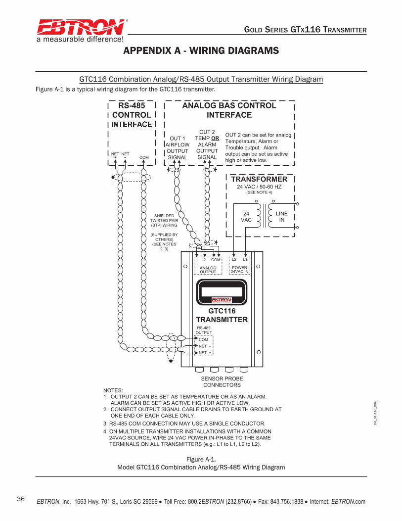
TM_G
Tx11
6_R
8A
a measurable difference!
®
GOLD SERIES GTX116 TRANSMITTER
EBTRON, Inc. 1663 Hwy. 701 S., Loris SC 29569 • Toll Free: 800.2EBTRON (232.8766) • Fax: 843.756.1838 • Internet: EBTRON.com36
GTC116 Combination Analog/RS-485 Output Transmitter Wiring DiagramFigure A-1 is a typical wiring diagram for the GTC116 transmitter.
APPENDIX A - WIRING DIAGRAMS
Figure A-1. Model GTC116 Combination Analog/RS-485 Wiring Diagram
TRANSFORMER24 VAC / 50-60 HZ
(SEE NOTE 4)
LINE IN
24VAC
SHIELDED TWISTED PAIR (STP) WIRING
(SUPPLIED BY OTHERS)
(SEE NOTES 2, 3)
RS-485CONTROL
GTC116TRANSMITTER
L2 L1
POWER24VAC IN
SENSOR PROBE CONNECTORS
RS-485 OUTPUT
COMNET -NET +
NET NET+ COM
OUT 1 AIRFLOW OUTPUTSIGNAL
1 2 COM
ANALOGOUTPUT
OUT 2TEMP ORALARM
OUTPUTSIGNAL
ANALOG BAS CONTROL INTERFACE
OUT 2 can be set for analog Temperature, Alarm or Trouble output. Alarm output can be set as active high or active low.
NOTES:1. OUTPUT 2 CAN BE SET AS TEMPERATURE OR AS AN ALARM.
ALARM CAN BE SET AS ACTIVE HIGH OR ACTIVE LOW.2. CONNECT OUTPUT SIGNAL CABLE DRAINS TO EARTH GROUND AT
ONE END OF EACH CABLE ONLY.3. RS-485 COM CONNECTION MAY USE A SINGLE CONDUCTOR.4. ON MULTIPLE TRANSMITTER INSTALLATIONS WITH A COMMON
24VAC SOURCE, WIRE 24 VAC POWER IN-PHASE TO THE SAMETERMINALS ON ALL TRANSMITTERS (e.g.: L1 to L1, L2 to L2).

TM_G
Tx11
6_R
8A
a measurable difference!
®
GOLD SERIES GTX116 TRANSMITTER
EBTRON, Inc. 1663 Hwy. 701 S., Loris SC 29569 • Toll Free: 800.2EBTRON (232.8766) • Fax: 843.756.1838 • Internet: EBTRON.com 37
GTM116 Combination Analog/Ethernet Output Transmitter Wiring Diagram
Figure A-2 is a typical wiring diagram for the GTM116 trans-mitter.
GTL116 LonWorks Output Transmitter Wiring Diagram
Figure A-3 is a typical wiring diagram for the GTL116 trans-mitter.
CAT 5 OR EQUIVALENT
WIRING
(SUPPLIED BY OTHERS)
ETHERNETBAS
INTERFACE
GTM116 TRANSMITTER
SENSOR PROBE CONNECTORS
RJ45 OUTPUT
BAS ETHERNET
TRANSFORMER24 VAC / 50-60 HZ
(See Note 3)
LINE IN
24VAC
SHIELDED TWISTED PAIR (STP) WIRING
(SUPPLIED BY OTHERS)
See Note 2
L2 L1
POWER24VAC IN
OUT 1AIRFLOW OUTPUTSIGNAL
1 2 COM
ANALOGOUTPUT
OUT 2*TEMP
ORALARM
OUTPUTSIGNAL
ANALOG BAS INTERFACE
*OUT 2 can be set as an analog Temperature, Alarm or Trouble output. Alarm output can be set as active high or active low.
NOTES:1. OUTPUT 2 CAN BE SET AS TEMPERATURE OR AS AN ALARM.
ALARM CAN BE SET AS ACTIVE HIGH OR ACTIVE LOW.
2. CONNECT OUTPUT SIGNAL CABLE DRAINS TO EARTH GROUND ATONE END OF EACH CABLE ONLY.
3. ON MULTIPLE TRANSMITTER INSTALLATIONS WITH A COMMON 24VAC SOURCE, WIRE 24 VAC POWER IN-PHASE TO THE SAMETERMINALS ON ALL TRANSMITTERS (e.g.: L1 to L1, L2 to L2).
TRANSFORMER24 VAC / 50-60 HZ
(SEE NOTE 3)
LINE IN
24VAC
USE LONWORKS®
COMPATIBLE SHIELDED TWISTED PAIR (STP)
CABLE(SUPPLIED BY OTHERS)
(SEE NOTES 1, 2)
LONWORKS®
BAS CONTROL INTERFACE
GTL116TRANSMITTER
L2 L1
POWER24VAC IN
SENSOR PROBE CONNECTORS
NET NET+
1 2 COM
OUTPUT
NOTES:1: REFER TO LONWORKS® FTT-10A Free Topology Transceiver User’s
Guide AVAILABLE AT www.echelon.com FOR LONWORKS® NETWORKWIRING SPECIFICATIONS AND TERMINATION REQUIREMENTS.
2. GTL116 CONNECTIONS AT TERMINALS 1 AND 2 (NET + and NET -) ARE NOT POLARITY SENSITIVE, AND THE COM CONNECTION IS NOT USED.
3. ON MULTIPLE GTL116 TRANSMITTER INSTALLATIONS WITH ACOMMON 24VAC SOURCE, WIRE 24 VAC CONNECTIONS IN-PHASE TOTHE SAME TERMINALS ON ALL TRANSMITTERS (e.g.: L1 to L1, L2 to L2).
APPENDIX A - WIRING DIAGRAMS (cont’d)
Figure A-3. Model GTL116
LonWorks Wiring Diagram
Figure A-2. Model GTM116
Combination Analog/Ethernet Wiring Diagram

TM_G
Tx11
6_R
8A
a measurable difference!
®
GOLD SERIES GTX116 TRANSMITTER
EBTRON, Inc. 1663 Hwy. 701 S., Loris SC 29569 • Toll Free: 800.2EBTRON (232.8766) • Fax: 843.756.1838 • Internet: EBTRON.com38
APPENDIX B -GTx116
SETUP MENUS
TM_G
Tx11
6_R
8A
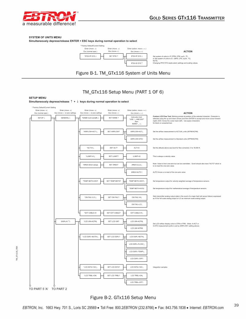
TM_G
Tx11
6_R
8A
a measurable difference!
®
GOLD SERIES GTX116 TRANSMITTER
EBTRON, Inc. 1663 Hwy. 701 S., Loris SC 29569 • Toll Free: 800.2EBTRON (232.8766) • Fax: 843.756.1838 • Internet: EBTRON.com 39
SYSTEM OF UNITS MENUSimultaneously depress/release ENTER + ESC keys during normal operation to select
* Factory Default/Current Setting
Enter (move ) Enter (move ) Enter (action, move )
Esc (normal oper.) Esc (move ) Esc (move ) ACTION
SET IP/SI ?*IP/SI=IP SYS IP/SI=IP SYS
IP/SI=SI SYS
Set system of units to I-P (FPM, CFM, sq.ft., ºF)or Set system of units to S.I. (MPS, LPS, sq.M., ºC).NOTE: Changing IP/SI SYS resets alarm settings and scaling values.
Figure B-2. GTx116 Setup Menu
SETUP MENUSimultaneously depress/release + keys during normal operation to select
* Factory Default/Current Setting
Enter (move ) Enter (move ) Enter (move ) Enter (move ) Enter (action, move )
Esc (normal oper.) Esc (move or prev setting) Esc (move or prev setting) Esc (move ) Esc (move ) ACTION
TO PART 5 'A' TO PART 2
AUTO forces a re-read of the one-wire value.
O
*LCD DSPL=BOTH
LCD UM=AFPM
*LCD INTG=100 SET LCD INTG? LCD INTG=100 Integration samples
SET LCD DSPL? LCD DSPL=BOTH
LCD DSPL=FLOW
*LCD TRBL=ON SET LCD TRBL? LCD TRBL=ON
ON FAIL=LO
*EXT CABLE=0 SET EXT CABLE? EXT CABLE=0
LCD DSPL=OFF
SETUP
*AIRFLOW=ACT SET AIRFLOW?
AIRFLOW=STD
Set the airflow measurement to ACTUAL units (AFPM/ACFM)
Set the airflow measurement to Standard units (SFPM/SCFM)
AIRFLOW=ACT
Custom LCD Flow Text: Blinking prompt at position of the selected character. Character is selected using the up and down arrows and then ENTER to accept and move cursor forward (right); ESC moves the cursor back (left). Use space charactersfor blank or unwanted text.
Instruction text: "USE AND ENT"
then:NAME= _
GENERAL *NAME={unit serial#} SET NAME ?
AREA=xx.xx
DISPLAY
ALT=0
*ON FAIL=LO SET ON FAIL? ON FAIL=HI
*LCD UM=ACFM
*LLIMIT=0 SET LLIMIT?
AREA=AUTO
*ALT=0 SET ALT?
This is always a velocity value.
*AREA={from setup}
Set the altitude above sea level for flow correction: 0 to 18,000 ft.
LLIMIT=0
SET LCD UM? LCD UM=ACFM
SET TEMP METH?*TEMP METH=WGT
SET AREA?Note: Value is from one-wire but can be overridden. Scroll should also have "AUTO" which is to re-read the one-wire value.
TEMP METH=WGT Set temperature output for velocity weighted average of temperature sensors.
TEMP METH=AVG Set temperature output for mathematical average of temperature sensors.
Sets transmitter analog output state in the event of a major fault (all sensor failure) expressed as HI for full scale analog output or LO as minimum scale analog output.
LCD DSPL=TEMP
Set LCD airflow display units to CFM or FPM. (Note: A-ACT or S-STD measurement prefix is set by AIRFLOW= setting above).
LCD TRBL=OFF
O
TM_GTx116 Setup Menu (PART 1 OF 6)
Figure B-1. TM_GTx116 System of Units Menu
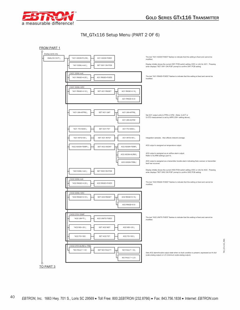
TM_G
Tx11
6_R
8A
a measurable difference!
®
GOLD SERIES GTX116 TRANSMITTER
EBTRON, Inc. 1663 Hwy. 701 S., Loris SC 29569 • Toll Free: 800.2EBTRON (232.8766) • Fax: 843.756.1838 • Internet: EBTRON.com40
FROM PART 1
Analog cards only
if AO1 SGNL=mA
if AO1 SGNL=VDC
AO2 output is assigned as temperature output.
if AO2 SGNL=mA
if AO2 SGNL=VDC
if AO2 CFG=TEMP
if AO2 CFG=ALRM or TRBL
TO PART 3O
O
*AO1 RNGE=0-10
*AO2 RNGE=4-20
AO2 output is assigned as a transmitter trouble alarm indicating that a sensor or transmitter fault has occurred.
Sets AO2 alarm/trouble output state when no fault condition is present, expressed as HI (full scale analog output) or LO (minimum scale analog output).
AO1 UM=ACFM
AO1 UM=AFPM
ANALOG OUT *AO1 ASGN=FLOW AO1 ASGN FIXEDThe text "AO1 ASGN FIXED" flashes to indicate that this setting is fixed and cannot be modified.
*A01 SGNL=mA SET SW1 ON PCBDisplay initially shows the current SW1 PCB switch setting (VDC or mA) for AO1. Pressing enter displays "SET SW1 ON PCB" prompt to confirm SW1 PCB setting.
*AO1 RNGE=4-20 AO1 RNGE=FIXEDThe text "AO1 RNGE=FIXED" flashes to indicate that this setting is fixed and cannot be modified.
SET AO1 RNGE? AO1 RNGE=0-10
AO1 RNGE=0-5
*AO1 UM=AFPM SET AO1 UM?
SET AO2 FS? AO2 FS=160
*AO1 FS=5000 SET AO1 FS? AO1 FS=5000
AO2 ASGN=TRBL
*AO1 INTG=30 SET AO1 INTG? AO1 INTG=30 Integration samples. Also affects network average.
*AO2 ASGN=TEMP SET AO2 ASGN? AO2 ASGN=TEMP
AO2 ASGN=ALRM
*A02 SGNL=mA SET SW2 ON PCBDisplay initially shows the current SW2 PCB switch setting (VDC or mA) for AO2. Pressing enter displays "SET SW2 ON PCB" prompt to confirm SW2 PCB setting.
AO2 output is assigned as an airflow alarm output. Refer to ALARM settings (part 4).
The text "AO2 UNITS FIXED" flashes to indicate that this setting is fixed and cannot be modified.
*NO FAULT = HI SET NO FAULT? NO FAULT = HI
AO2 RNGE=FIXEDThe text "AO2 RNGE=FIXED" flashes to indicate that this setting is fixed and cannot be modified.
*AO2 RNGE=0-10 SET AO2 RNGE? AO2 RNGE=0-10
NO FAULT = LO
Set AO1 output units to FPM or CFM. (Note: A-ACT or S-STD measurement is set by AIRFLOW= setting above).
*AO2 MS=-20 SET AO2 MS? AO2 MS=-20
*AO2 FS=160
AO2 RNGE=0-5
*AO2 UM= F AO2 UNITS FIXED
TM_GTx116 Setup Menu (PART 2 OF 6)
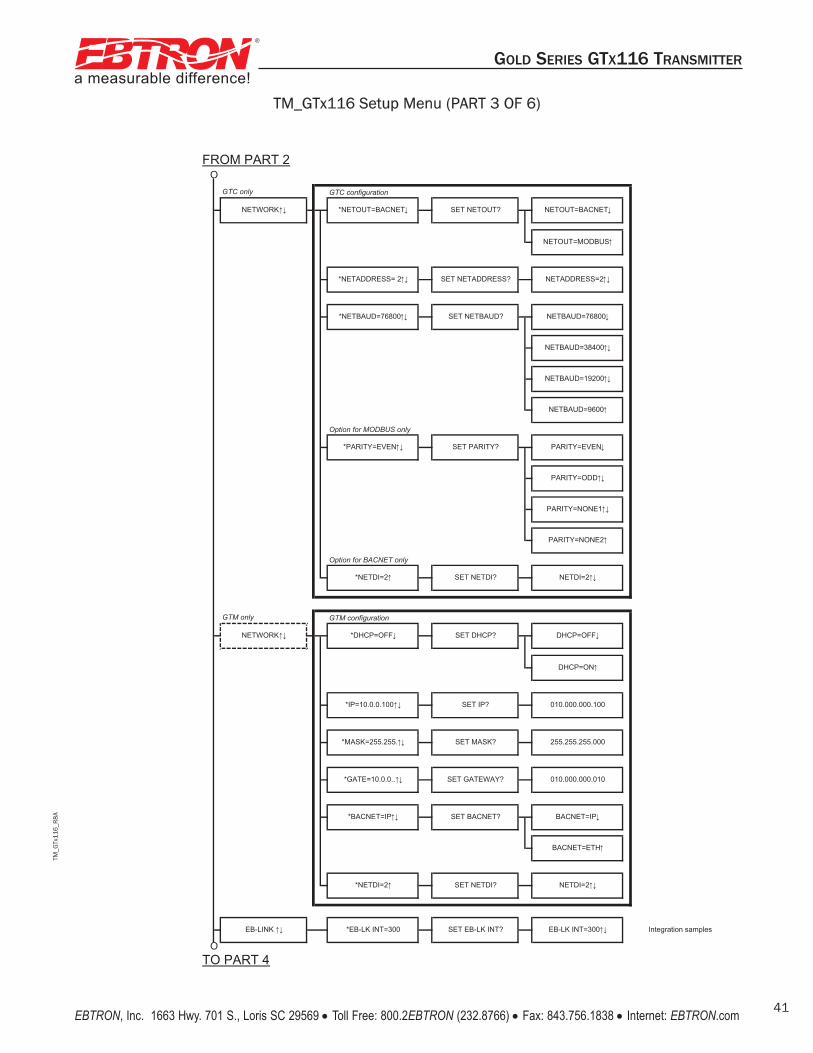
TM_G
Tx11
6_R
8A
a measurable difference!
®
GOLD SERIES GTX116 TRANSMITTER
EBTRON, Inc. 1663 Hwy. 701 S., Loris SC 29569 • Toll Free: 800.2EBTRON (232.8766) • Fax: 843.756.1838 • Internet: EBTRON.com 41
FROM PART 2
GTC only GTC configuration
Option for MODBUS only
Option for BACNET only
GTM only GTM configuration
TO PART 4
*EB-LK INT=300 SET EB-LK INT? EB-LK INT=300 Integration samples
*NETDI=2 SET NETDI? NETDI=2
SET GATEWAY? 010.000.000.010
NETDI=2
*DHCP=OFF
PARITY=NONE1
NETOUT=MODBUS
*NETADDRESS= 2 NETADDRESS=2
SET DHCP? DHCP=OFF
*BACNET=IP SET BACNET?
*MASK=255.255. SET MASK? 255.255.255.000
BACNET=ETH
*GATE=10.0.0..
DHCP=ON
NETBAUD=19200
NETBAUD=9600
BACNET=IP
PARITY=NONE2
NETBAUD=38400
*NETDI=2 SET NETDI?
010.000.000.100
*NETBAUD=76800 SET NETBAUD? NETBAUD=76800
*PARITY=EVEN SET PARITY? PARITY=EVEN
PARITY=ODD
*NETOUT=BACNET SET NETOUT? NETOUT=BACNET
NETWORK
O
O
SET IP?
SET NETADDRESS?
NETWORK
*IP=10.0.0.100
EB-LINK
TM_GTx116 Setup Menu (PART 3 OF 6)

TM_G
Tx11
6_R
8A
a measurable difference!
®
GOLD SERIES GTX116 TRANSMITTER
EBTRON, Inc. 1663 Hwy. 701 S., Loris SC 29569 • Toll Free: 800.2EBTRON (232.8766) • Fax: 843.756.1838 • Internet: EBTRON.com42
TM_GTx116 Setup Menu (PART 4 OF 6)
FROM PART 3
TO PART 5 'B'
RESET=MANUAL
SET ZERO OFF? ZERO OFF=NO
ZERO OFF=YES
*RESET=AUTO SET RESET? RESET=AUTO
*ZERO OFF=NO
*TOL=10% SET TOL? TOL=10%
*DELAY=5 SET DELAY? DELAY=2 MIN
ALRM UM=ACFM
*SETPNT=0 SET SETPNT? SETPNT=0
ALARM
HI ALRM=ON
*ALRM UM=AFPM SET ALRM UM? ALRM UM=AFPM
LO ALRM=ON
SET LO ALRM? LO ALRM=OFF*LO ALRM=OFF
*HI ALRM=OFF SET HI ALRM? HI ALRM=OFF
When ZERO OFF=YES, this setting is used to inhibit the LO ALRM condition when the unit is reading 0. This is dependent on the low limit setting.
O
O
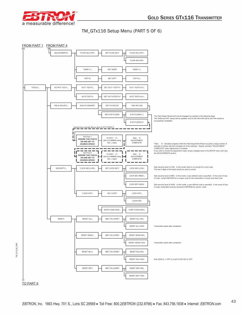
TM_G
Tx11
6_R
8A
a measurable difference!
®
GOLD SERIES GTX116 TRANSMITTER
EBTRON, Inc. 1663 Hwy. 701 S., Loris SC 29569 • Toll Free: 800.2EBTRON (232.8766) • Fax: 843.756.1838 • Internet: EBTRON.com 43
FROM PART 1 FROM PART 4
Dashed lines indicate Menus when # OF FLOWS=2
TO PART 6
TOOLS
"Wait. . . %" indicates progress while the Field Adjustment Wizard acquires a large number of samples of airflow rate and averages all of the readings. Display indicates "ADJUSTMENT COMPLETE" when adjustment is complete. If you wish to review the adjustment made, simply navigate back to the SETUP menu and view the ADJUSTMENTS section.
O
5A
RESET ADJ ARE YOU SURE?
RESET NET=YES
Sets security level to LOW. In this mode, there is no prompt for a lock code. The last 4 digits of the board serial are used to unlock.
Transmitter resets after completion
Transmitter resets after completion
RESET NET=NO
LOCK SEC=MED
RESET ADJ=YES Sets GAIN to 1, OFF to 0 and FLOW ADJ to OFF
RESET ALL=YES
RESET SENS ARE YOU SURE? RESET SENS=NO
RESET SENS=YES
*LOCK=OFF SET LOCK? LOCK=OFF
LOCK=ON
ENTR CODE:0000 CONF CODE:0000
LOCK SET=HIGH
RESET ADJ=NO
RESET RESET ALL ARE YOU SURE? RESET ALL=NO
RESET NET ARE YOU SURE?
SET # OF FLOWS # OF FLOWS=1
SECURITY *LOCK SEC=LOW SET LOCK SEC? LOCK SEC=LOW
FLOW2= 0(Set 0 to 999999 using
the keys)
Wait. . .%ADJUSTMENT
COMPLETE
Set Flow 2ENSURE THAT FAN IS
ON AND SET TO DESIRED SPEED!
FLOW1= 0(Set 0 to 999999 using
the keys)
OUT2 TEST% SET OUT12TEST%? OUT2 TEST%=0
OUTPUT TEST
FIELD ADJUST RUN FA WIZARD? SET FA WIZ INT FAW INT=300
OFF=0
# OF FLOWS=2
ADJUSTMENTS
*OFF=0 SET OFF?
OUT1 TEST% SET OUT1 TEST%? OUT1 TEST%=0
FLOW ADJ=ON
*GAIN=1 SET GAIN? GAIN=1
SET FLOW ADJ? FLOW ADJ=OFF
The Field Adjust Wizard will now be engaged as outlined in the following steps. The GAIN and OFF values will be updated, and FLOW ADJ=ON will be set if the wizard is successfully completed.
*FLOW ADJ=OFF
5B
Sets security level to MED. In this mode, a user defined code is specified. In the event of loss of code, contact EBTRON for a unique code for this transmitter to unlock and reset code.
Sets security level to HIGH. In this mode, a user defined code is specified. In the event of loss of code, transmitter must be returned to EBTRON for unlock / reset.
Set Flow 1ENSURE THAT FAN IS
ON AND SET TO DESIRED SPEED!
Wait. . .%ADJUSTMENT
COMPLETE
TM_GTx116 Setup Menu (PART 5 OF 6)

TM_G
Tx11
6_R
8A
a measurable difference!
®
GOLD SERIES GTX116 TRANSMITTER
EBTRON, Inc. 1663 Hwy. 701 S., Loris SC 29569 • Toll Free: 800.2EBTRON (232.8766) • Fax: 843.756.1838 • Internet: EBTRON.com44
TM_GTx116 Setup Menu (PART 6 OF 6)
FROM PART 5
1: NO PROBES
(example shown)
For sensors =1 to 9, A to G
For sensors =1 to 9, A to G
For sensors =1 to 9, A to G
O
SENS VOLTS 1=H##.## T##.##
1=##.#F
BRD #####
DIAGNOSTICS
SENS VELOCITY 1=#####FPM
SENS TEMP
C3 ###### T
C4 ###### F
Note: Show serial number or NC by connector #
DSBL TRBL CODE? DSBL TRBL=NO
C1 ###### T
C2 ###### F
1: NO PROBES(example shown)
Displays historical list of trouble codes encountered and their descriptions. Note that spurious trouble codes may self-clear during normal operation, and this feature permits viewing them even after they have resolved.
DSBL TRBL=YES
Displays active trouble codes and their descriptions. Contact EBTRON customer service for recommended service information.
Set DSBL TRBL= YES to ignore on TRBL alarm.
SERIAL NUMBERS UNIT #######
TRBL CODES
TRBL HISTORY