GOES-R Calibration Working Group Progress Update€¦ · GOES-R Calibration Working Group Progress...
20
GOES-R Calibration Working Group Progress Update Changyong Cao With contributions from B. Iacovazzi, A. Pearlman, D. Pogorzala, X. Shao, Raju Datla, and S. Uprety NOAA/NESDIS/STAR GOES‐R Calibration Working Group 1 January 2012
Transcript of GOES-R Calibration Working Group Progress Update€¦ · GOES-R Calibration Working Group Progress...
GOES-R Calibration Working Group Progress Update
Changyong CaoWith contributions from B. Iacovazzi, A. Pearlman, D.
Pogorzala, X. Shao, Raju Datla, and S. UpretyPogorzala, . Shao, Raju Datla, and S. Uprety
NOAA/NESDIS/STARGOES‐R Calibration Working Group
1
January 2012
GOES‐R Calibration Working Group (CWG)g p ( )
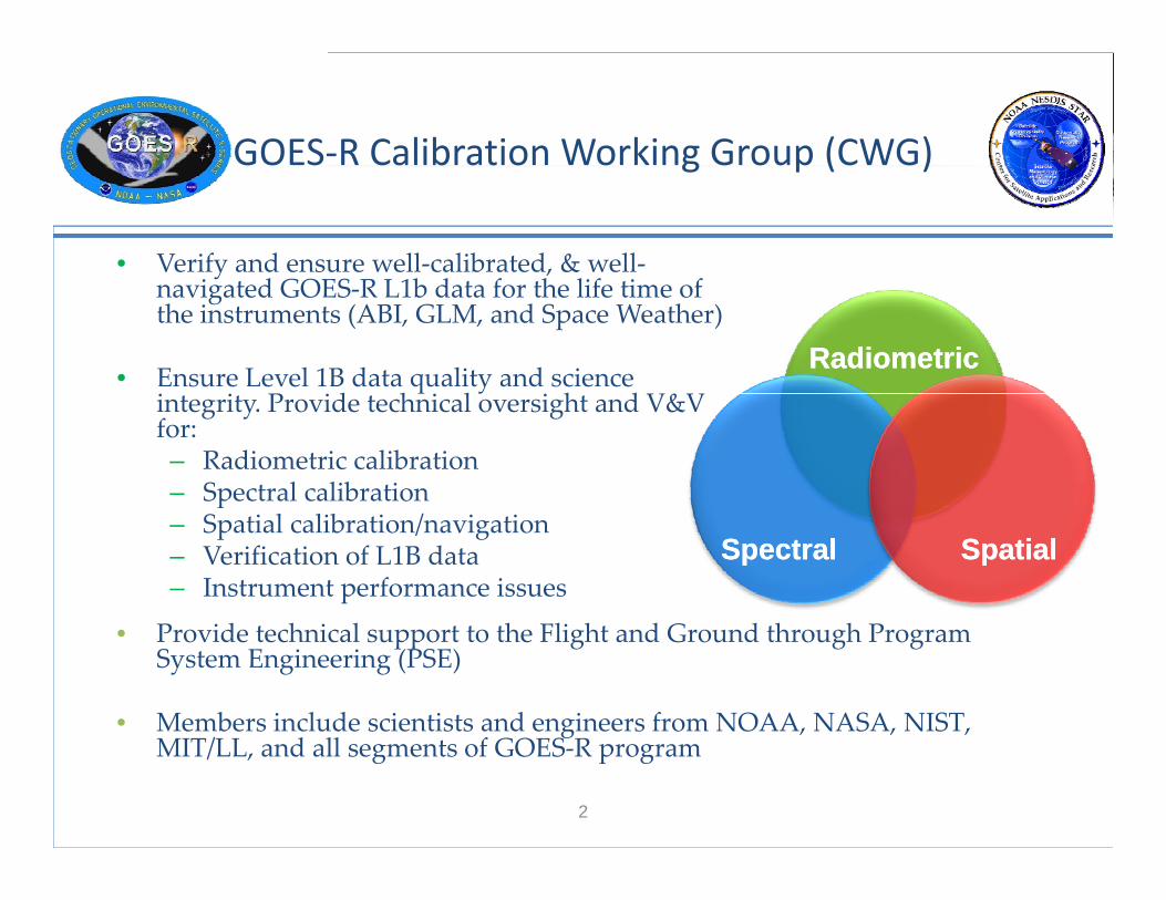
• Verify and ensure well‐calibrated, & well‐i d GOES R L1b d f h lif i f
RadiometricRadiometric
navigated GOES‐R L1b data for the life time of the instruments (ABI, GLM, and Space Weather)
• Ensure Level 1B data quality and science P d h l h d V&V
q yintegrity. Provide technical oversight and V&V for:– Radiometric calibration– Spectral calibration
SpectralSpectral SpatialSpatial
p– Spatial calibration/navigation– Verification of L1B data– Instrument performance issues
• Provide technical support to the Flight and Ground through Program System Engineering (PSE)
• Members include scientists and engineers from NOAA, NASA, NIST,
2
g , , ,MIT/LL, and all segments of GOES‐R program

Calibration Coordination Team (CCT) Formed Under PSE
Scope – A coordinating body to ensure efficient implementation of calibration activities throughout the GOES-R Program during all mission phases.
AWG/CWG
DOSTCCT members - Representatives of any group with responsibility to ensure L1b Product integrity, e.g.,
PSE & Program Science
MOST
GOES‐R Calibration
• PSE & Program Science (Cal/Val Working Group Reps)
• Flight (Deputy Project Manager, Instrument Managers)
FlightGS Vendor
GOES R Calibration Coordination Team • GSP (Ground System Project)
• Vendors (Instrument, Spacecraft and Ground)
• AWG (Algorithm Working
GSPInstr./SC Vendor
Group)• MOST (Mission Operations
Support Team)• DOST (Data Operations Support
3
GOES-R Calibration Coordination Team membership diagram
Team)
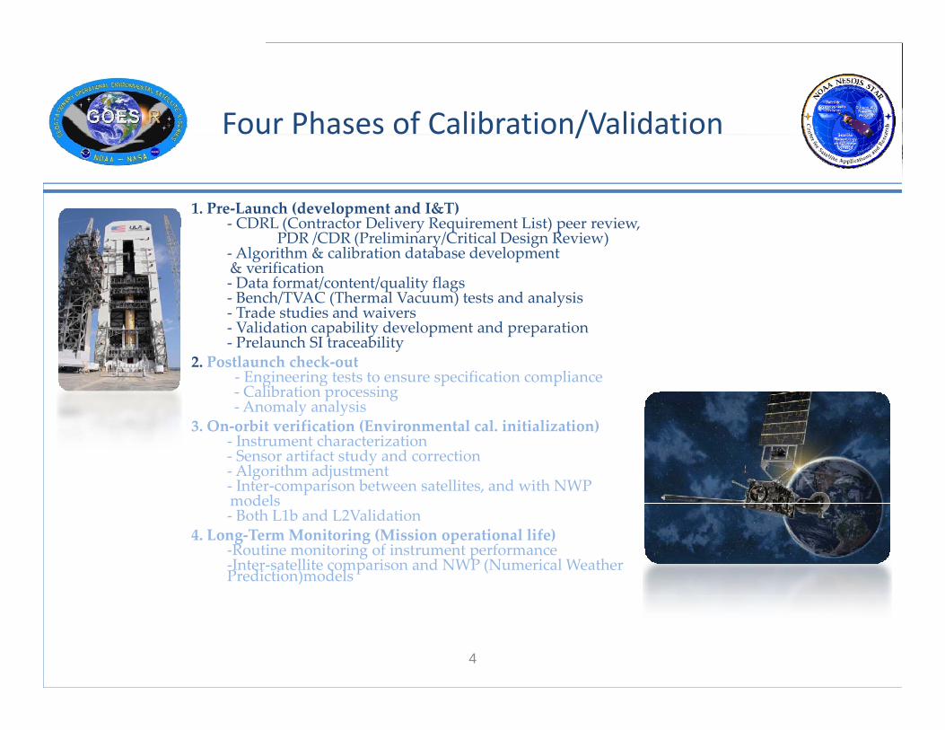
Four Phases of Calibration/Validation/
1. Pre‐Launch (development and I&T)‐ CDRL (Contractor Delivery Requirement List) peer review,CDRL (Contractor Delivery Requirement List) peer review,
PDR /CDR (Preliminary/Critical Design Review)‐Algorithm & calibration database development & verification‐ Data format/content/quality flags‐ Bench/TVAC (Thermal Vacuum) tests and analysis‐ Trade studies and waivers ‐ Validation capability development and preparation‐ Prelaunch SI traceability
2. Postlaunch check‐out ‐ Engineering tests to ensure specification compliance‐ Calibration processing‐Anomaly analysisAnomaly analysis
3. On‐orbit verification (Environmental cal. initialization) ‐ Instrument characterization‐ Sensor artifact study and correction‐Algorithm adjustment‐ Inter‐comparison between satellites, and with NWPmodelsmodels‐ Both L1b and L2Validation
4. Long‐Term Monitoring (Mission operational life)‐Routine monitoring of instrument performance‐Inter‐satellite comparison and NWP (Numerical Weather Prediction)models
4
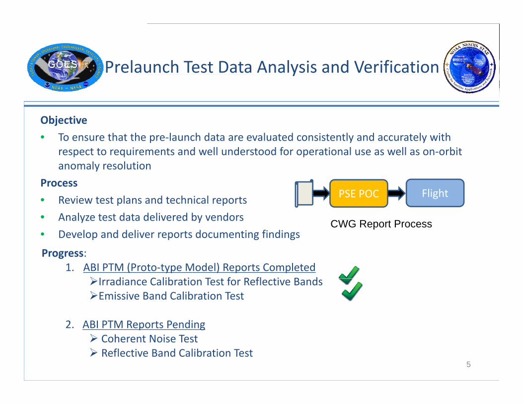
Prelaunch Test Data Analysis and Verificationy
Objectivej
• To ensure that the pre‐launch data are evaluated consistently and accurately with respect to requirements and well understood for operational use as well as on‐orbit anomaly resolution
Process
• Review test plans and technical reports
• Analyze test data delivered by vendors
PSE POC Flight
CWG Report Process • Develop and deliver reports documenting findings
Progress:1. ABI PTM (Proto‐type Model) Reports Completed
I di C lib ti T t f R fl ti B d
p
Irradiance Calibration Test for Reflective BandsEmissive Band Calibration Test
2. ABI PTM Reports Pending
5
p g Coherent Noise Test Reflective Band Calibration Test
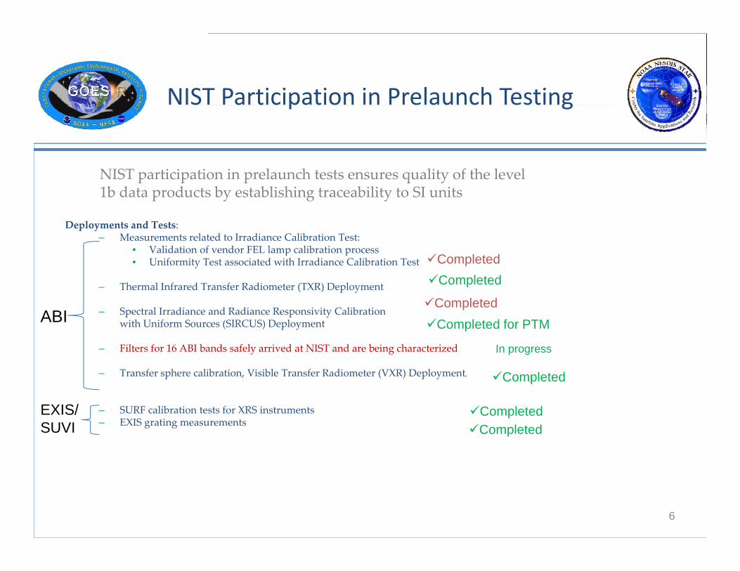
NIST Participation in Prelaunch Testingp g
NIST participation in prelaunch tests ensures quality of the level
Deployments and Tests:– Measurements related to Irradiance Calibration Test:
• Validation of vendor FEL lamp calibration process
NIST participation in prelaunch tests ensures quality of the level 1b data products by establishing traceability to SI units
• Validation of vendor FEL lamp calibration process• Uniformity Test associated with Irradiance Calibration Test
– Thermal Infrared Transfer Radiometer (TXR) Deployment
– Spectral Irradiance and Radiance Responsivity Calibration ith U if S (SIRCUS) D l t
Completed
Completed
Completed
C l t d f PTMABI with Uniform Sources (SIRCUS) Deployment
– Filters for 16 ABI bands safely arrived at NIST and are being characterized
– Transfer sphere calibration, Visible Transfer Radiometer (VXR) Deployment,
Completed for PTMABI
Completed
In progress
– SURF calibration tests for XRS instruments– EXIS grating measurements
Completed EXIS/SUVI
Completed
6

External Calibration Target (ECT) Characterization using NIST TXRCharacterization using NIST TXR
View to ECT
TXR (Th l T fTXR (Thermal Transfer Radiometer) used for-Establishing prelaunch SI traceabilityy-Blackbody emissivity characterization
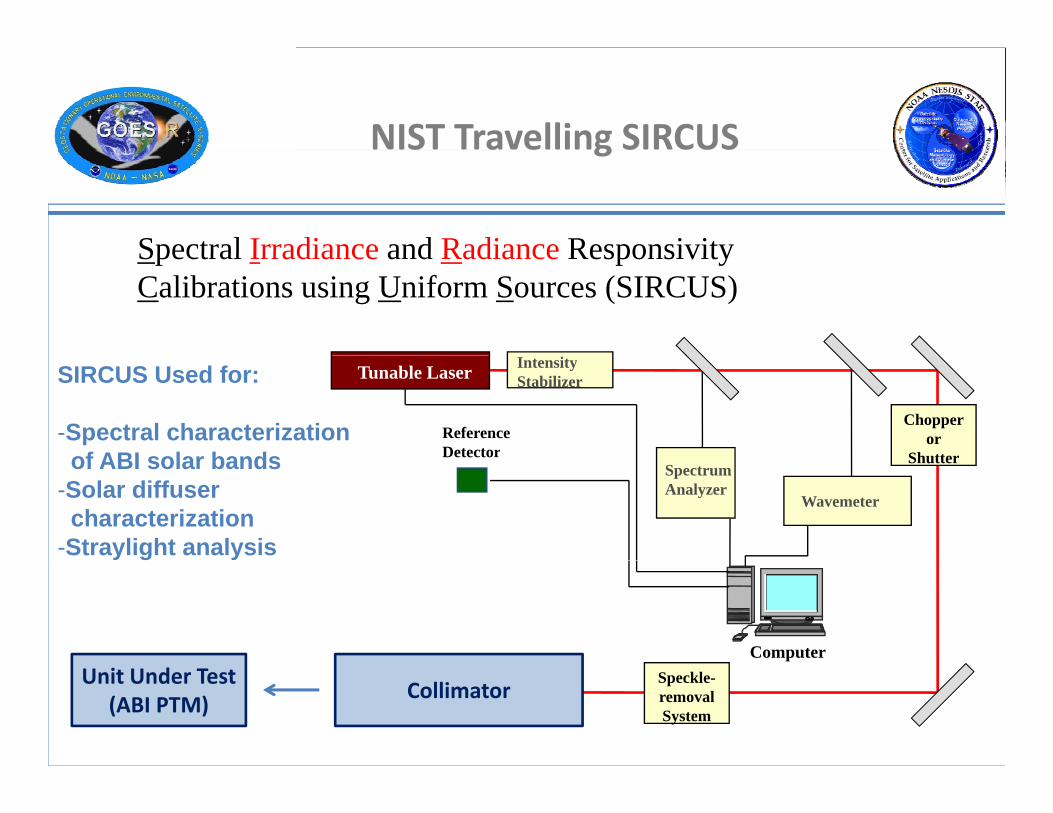
NIST Travelling SIRCUSg
Spectral Irradiance and Radiance ResponsivitySpectral Irradiance and Radiance Responsivity Calibrations using Uniform Sources (SIRCUS)
Tunable Laser
ReferenceDetector
IntensityStabilizer
Chopperor
Shutter
SIRCUS Used for:
-Spectral characterizationof ABI solar bands
Wavemeter
Spectrum Analyzer
Shutterof ABI solar bands-Solar diffuser characterization
-Straylight analysis
ComputerSpeckle-removalSystem
CollimatorUnit Under Test
(ABI PTM)

ABI PFM Spectral Response Functions
•ABI PFM (Proto-flight Model) =flight model
•Public version of ABI PFM Spectral Response Functions (SRFs) are made available
•SRFs were analytically Generated (ANGEN)
•Witness sample filters will beWitness sample filters will be tested at NIST
9
ABI PFM SRF available at : https://cs.star.nesdis.noaa.gov/GOESRCWG/PublicData
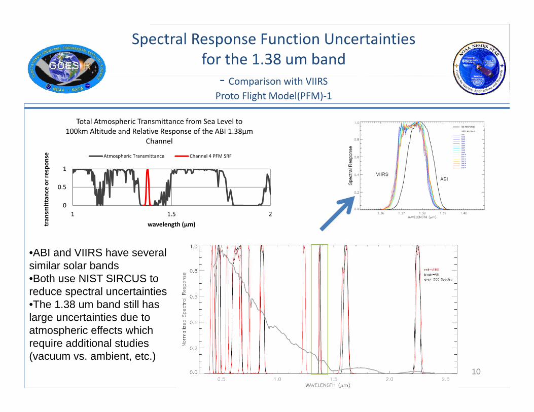
Spectral Response Function Uncertainties for the 1.38 um band
‐ Comparison with VIIRSProto Flight Model(PFM)‐1
Total Atmospheric Transmittance from Sea Level to
1
r respon
se
100km Altitude and Relative Response of the ABI 1.38µm Channel
Atmospheric Transmittance Channel 4 PFM SRF
0
0.5
1 1.5 2
tran
smittance or
wavelength (µm)
•ABI and VIIRS have several similar solar bands•Both use NIST SIRCUS to reduce spectral uncertainties•The 1.38 um band still has large uncertainties due to atmospheric effects which
10
require additional studies (vacuum vs. ambient, etc.)

Mitigation for ABI SRF UncertaintiesMitigation for ABI SRF Uncertainties
NIST SIRCUS Test and Data Anal sisNIST SIRCUS Test and Data Analysis• Analyze SIRCUS data to verify ANGEN for PTM.• Compare SIRCUS results of ABI vs VIIRS
PFM Witness Filter Measurements• NIST to measure witness filters for the ABI PFM for all bands to
– Reproduce vendor resultsReproduce vendor results– Examine dependence on temperature and angle of incidence– Measure filters in flight conditions
• Analyze NIST witness filter measurements and recreate ANGEN for PFM to evaluate uncertaintiesevaluate uncertainties.
MODTRAN Simulations• Perform simulations to understand potential impacts of SRF differences• Perform simulations to understand potential impacts of SRF differences.
11
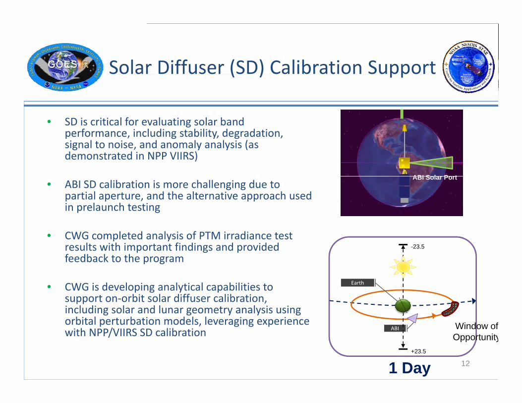
Solar Diffuser (SD) Calibration Support( ) pp
• SD is critical for evaluating solar band S s c t ca o e a uat g so a ba dperformance, including stability, degradation, signal to noise, and anomaly analysis (as demonstrated in NPP VIIRS)
ABI Solar Port• ABI SD calibration is more challenging due to
partial aperture, and the alternative approach used in prelaunch testing
ABI Solar Port
• CWG completed analysis of PTM irradiance test results with important findings and provided feedback to the program
-23.5
• CWG is developing analytical capabilities to support on‐orbit solar diffuser calibration, including solar and lunar geometry analysis using orbital perturbation models, leveraging experience i h NPP/VIIRS SD lib i
Earth
ABI Window ofwith NPP/VIIRS SD calibration
12
ABI
+23.5
1 Day
Window of Opportunity
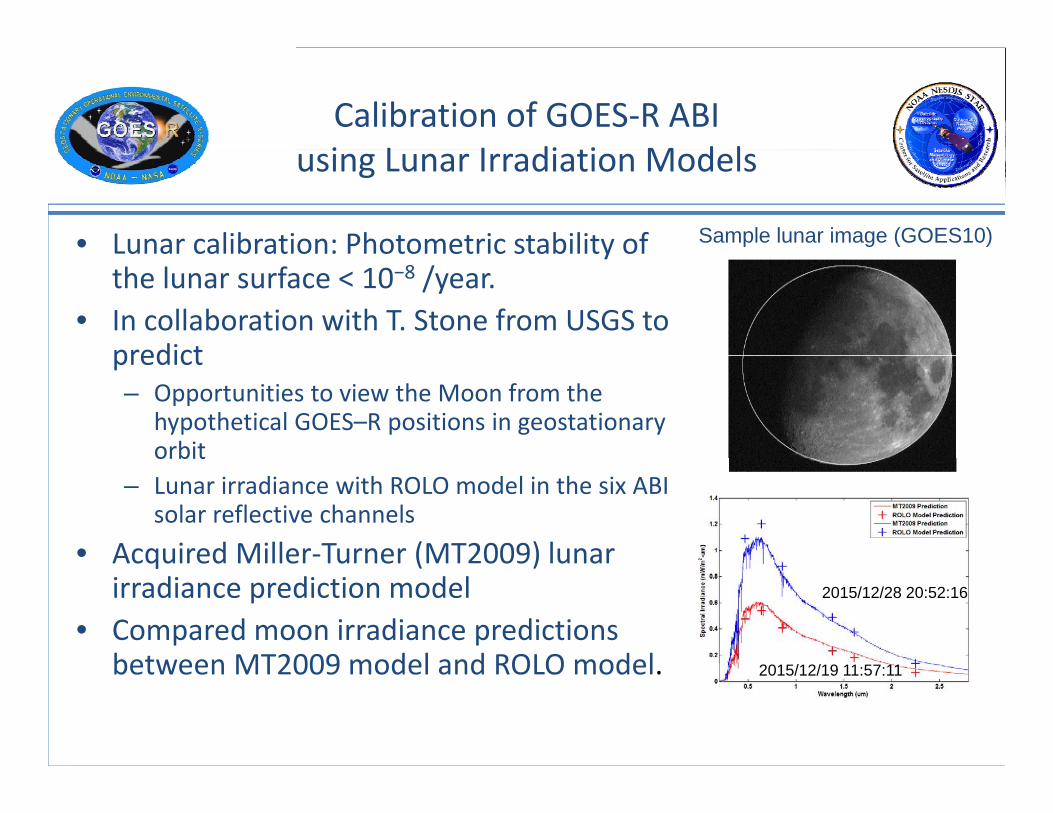
Calibration of GOES‐R ABI i L I di ti M d lusing Lunar Irradiation Models
• Lunar calibration: Photometric stability of Sample lunar image (GOES10)Lunar calibration: Photometric stability of the lunar surface < 10−8 /year.
• In collaboration with T. Stone from USGS to predictpredict– Opportunities to view the Moon from the
hypothetical GOES–R positions in geostationary orbitorbit
– Lunar irradiance with ROLO model in the six ABI solar reflective channels
• Acquired Miller‐Turner (MT2009) lunarAcquired Miller Turner (MT2009) lunar irradiance prediction model
• Compared moon irradiance predictions between MT2009 model and ROLO model
2015/12/28 20:52:16
between MT2009 model and ROLO model. 2015/12/19 11:57:11
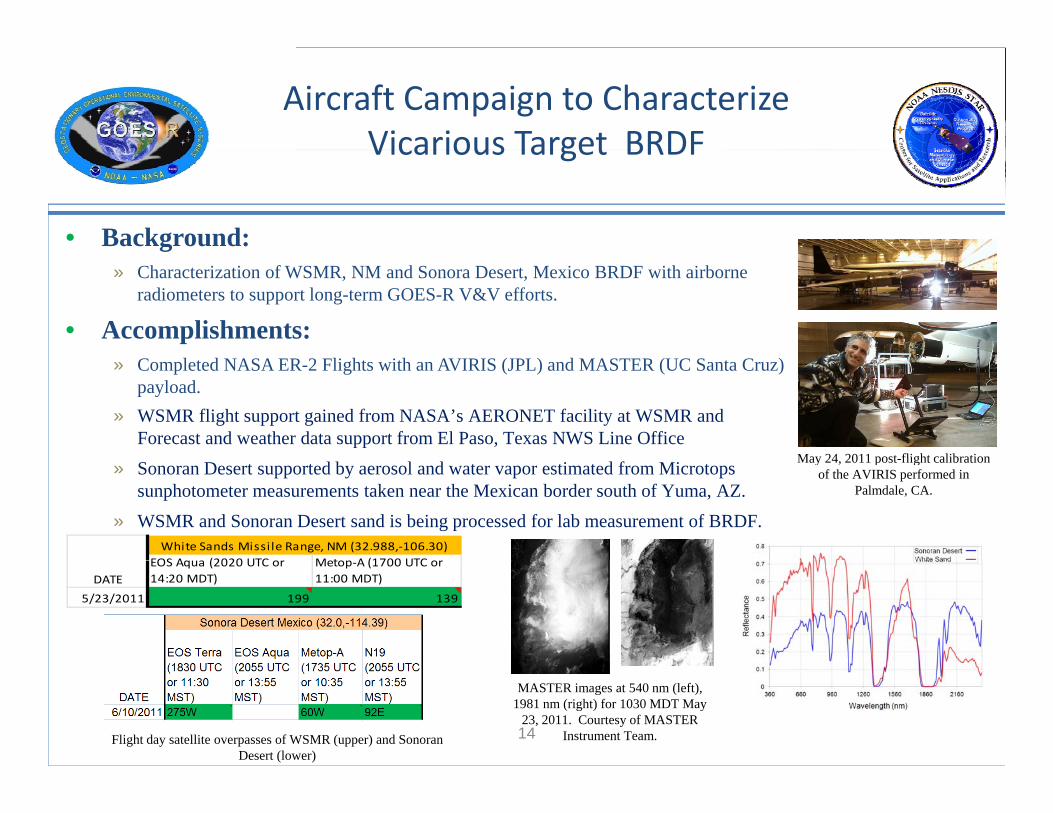
Aircraft Campaign to Characterize Vicarious Target BRDFVicarious Target BRDF
• Background:» Characterization of WSMR, NM and Sonora Desert, Mexico BRDF with airborne
radiometers to support long-term GOES-R V&V efforts.
• Accomplishments:» Completed NASA ER-2 Flights with an AVIRIS (JPL) and MASTER (UC Santa Cruz)
payload. » WSMR flight support gained from NASA’s AERONET facility at WSMR and
Forecast and weather data support from El Paso, Texas NWS Line OfficeMay 24 2011 post flight calibration» Sonoran Desert supported by aerosol and water vapor estimated from Microtops
sunphotometer measurements taken near the Mexican border south of Yuma, AZ.» WSMR and Sonoran Desert sand is being processed for lab measurement of BRDF.
EOS Aqua (2020 UTC or Metop A (1700 UTC orWhite Sands Missile Range, NM (32.988,‐106.30)
May 24, 2011 post-flight calibration of the AVIRIS performed in
Palmdale, CA.
EOS Aqua (2020 UTC or 14:20 MDT)
Metop‐A (1700 UTC or 11:00 MDT)
5/23/2011 199 139
DATE
14
MASTER images at 540 nm (left), 1981 nm (right) for 1030 MDT May
23, 2011. Courtesy of MASTER Instrument Team.Flight day satellite overpasses of WSMR (upper) and Sonoran
Desert (lower)

Ground Instruments for ABI Cal/ValGround Instruments for ABI Cal/Val
• Support spectral and radiometric calibration for underflights• New ground instruments for vicarious cal/val
– Sun photometer [540 Microtops II (Solar Light)]
• Measuring total incoming and reflected radiance for ABI VNIR channel
– Spectroradiometer [ASD FieldSpec Hi‐Res] p [ p ]
• Spectral characterization of surface (covers all ABI VNIR channels)
• Validation for GOES‐R/ABI
– Thermal Imager – [FLIR T400]
• Broadband radiance in all emissive channels• Broadband radiance in all emissive channels
• Currently developing capability to deploy these instruments.
ASD
15
Summaryy
GOES‐R Cal/Val Working Group:GOES‐R Cal/Val Working Group:– Fully engaged in all segments of the GOES‐R program to provide V&V and Cal/Val support
– Made definitive progress in prelaunch test data analysis and post launch capability p g p y p p ydevelopment
– Strengthening collaboration with different segments of the GOES‐R program and member organizationsg
– Leveraging vast experiences and expertise with other programs such as NPP VIIRS
Will ll b t i t ti ll ith JMA (J M t l i l A ) AHI– Will collaborate internationally with JMA (Japanese Meteorological Agency) on AHI (Advanced Himawari Imager)
16
• Backup slidesBackup slides
17

Cross Calibration between POES JPSS d GOES RPOES, JPSS, and GOES-R
GOES-15 vs NPPE h d bit l di ti•Enhanced orbital prediction capabilities for simultaneous nadir observations between polar-orbiting and geostationary satellites g y
•Leveraging existing cross-calibration efforts such as GSICS
•Expanding the prediction to include lunar and solar diffuser calibration

On‐Orbit Modulation Transfer Function (MTF) Evaluation(MTF) Evaluation
The lunar edge near the equator isLunar edge (curvature exaggerated)
The lunar edge near the equator is approximately vertically aligned, and its position at each line changes, allowing a sub‐pixel measurement by combining the
Sub‐pixel measurement
lines.
Eff t b d i t d Sh J J 1999 L li bEfforts based on previous study: Shea, J. J., 1999: Lunar limb Knife-edge optical transfer function measurements, Journal of Electronic Imaging, 8(2), 196-208.
19
The lunar edge is tracked at the sub-pixel level.
Lines of data assembled from a lunar image creates an Edge-Spread Function (ESF). Combining lines relative to lunar edge creates a sub-pixel measurement.
The spatial derivative of an Edge-Spread Function is a Line-Spread Function.
The modulus of the Fourier Transform of the Line-Spread Function is the Modulation Transfer Function (MTF).
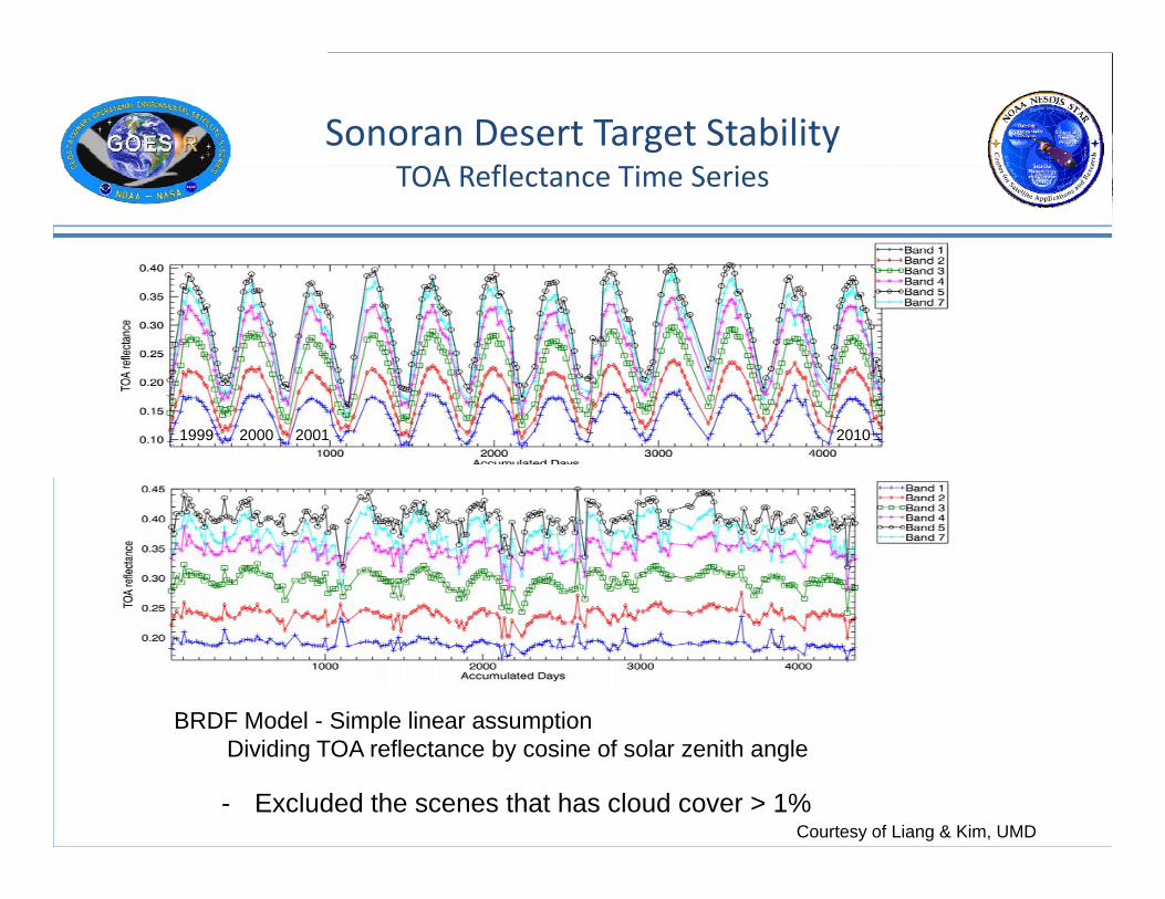
Sonoran Desert Target StabilityTOA R fl Ti S iTOA Reflectance Time Series
1999 2000 2001 2010
BRDF Model - Simple linear assumption
- Excluded the scenes that has cloud cover > 1%
Dividing TOA reflectance by cosine of solar zenith angle
Courtesy of Liang & Kim, UMD